- Table of Contents
-
- 05-Layer 3-IP Routing Configuration Guide
- 00-Preface
- 01-Basic IP routing configuration
- 02-Static routing configuration
- 03-RIP configuration
- 04-OSPF configuration
- 05-IS-IS configuration
- 06-BGP configuration
- 07-Policy-based routing configuration
- 08-IPv6 static routing configuration
- 09-RIPng configuration
- 10-OSPFv3 configuration
- 11-IPv6 policy-based routing configuration
- 12-Routing policy configuration
- Related Documents
-
| Title | Size | Download |
|---|---|---|
| 09-RIPng configuration | 248.78 KB |
Contents
RIPng packets and advertisement
Configuring RIPng route control
Configuring an additional routing metric
Configuring RIPng route summarization··
Configuring received/redistributed route filtering
Setting a preference for RIPng
Configuring RIPng route redistribution··
Tuning and optimizing the RIPng network
Configuring split horizon and poison reverse
Setting the maximum number of ECMP routes
Configuring the RIPng packet sending rate·
Setting the interval for sending triggered updates
Restrictions and guidelines for RIPng FRR
Configuring zero field check for RIPng packets
Display and maintenance commands for RIPng
Example: Configuring basic RIPng
Example: Configuring RIPng route redistribution
Example: Configuring RIPng NSR
Example: Configuring RIPng FRR
Example: Using an IPsec profile to protect RIPng
Configuring RIPng
About RIPng
RIP next generation (RIPng), as an extension of RIP-2 for support of IPv6, is a distance vector routing protocol. It employs UDP to exchange route information through port 521. Most RIP concepts are applicable to RIPng.
RIPng routing metrics
RIPng uses a hop count to measure the distance to a destination. The hop count is the metric or cost. The hop count from a router to a directly connected network is 0. The hop count between two directly connected routers is 1. When the hop count is greater than or equal to 16, the destination network or host is unreachable.
RIPng route entries
RIPng stores route entries in a database. Each route entry contains the following elements:
· Destination address—IPv6 address of a destination host or a network.
· Next hop address—IPv6 address of the next hop.
· Egress interface—Egress interface of the route.
· Metric—Cost from the local router to the destination.
· Route time—Time elapsed since the most recent update. The time is reset to 0 every time the route entry is updated.
· Route tag—Used for route control. For more information, see "Configuring routing policies."
RIPng packets and advertisement
RIPng multicasts request and response packets to exchange routing information. It uses FF02::9 as the link-local-router multicast address and FE80::/10 as the link-local source address. RIPng exchanges routing information as follows:
1. When RIPng starts or needs to update some route entries, it sends a multicast request packet to neighbors.
2. When a RIPng neighbor receives the request packet, it sends back a response packet that contains the local routing table. RIPng can also advertise route updates in response packets periodically or advertise a triggered update caused by a route change.
3. After RIPng receives the response, it checks the validity of the response before adding routes to its routing table, including the following details:
¡ Whether the source IPv6 address is the link-local address.
¡ Whether the port number is correct.
4. A response packet that fails the check is discarded.
Protocols and standards
· RFC 2080, RIPng for IPv6
· RFC 2081, RIPng Protocol Applicability Statement
RIPng tasks at a glance
To configure RIPng, perform the following tasks:
2. (Optional.) Configuring RIPng route control
¡ Configuring an additional routing metric
¡ Configuring RIPng route summarization
¡ Configuring received/redistributed route filtering
¡ Setting a preference for RIPng
¡ Configuring RIPng route redistribution
3. (Optional.) Tuning and optimizing the RIPng network
¡ Configuring split horizon and poison reverse
¡ Setting the maximum number of ECMP routes
¡ Configuring the RIPng packet sending rate
¡ Setting the interval for sending triggered updates
4. (Optional.) Enhancing RIPng availability
5. (Optional.) Enhancing RIPng security
¡ Configuring zero field check for RIPng packets
Configuring basic RIPng
1. Enter system view.
system-view
2. Enable RIPng and enter its view.
ripng [ process-id ] [ vpn-instance vpn-instance-name ]
By default, RIPng is disabled.
3. Return to system view.
quit
4. Enter interface view.
interface interface-type interface-number
5. Enable RIPng on the interface.
ripng process-id enable
By default, RIPng is disabled on the interface.
If RIPng is not enabled on an interface, the interface does not send or receive any RIPng route.
Configuring RIPng route control
Configuring an additional routing metric
About additional routing metrics
An additional routing metric (hop count) can be added to the metric of an inbound or outbound RIPng route.
· An outbound additional metric is added to the metric of a sent route, and it does not change the route's metric in the routing table.
· An inbound additional metric is added to the metric of a received route before the route is added into the routing table, and the route's metric is changed.
Procedure
1. Enter system view.
system-view
2. Enter interface view.
interface interface-type interface-number
3. Specify an inbound additional routing metric.
ripng metricin value
The default additional metric of an inbound route is 0.
4. Specify an outbound additional routing metric.
ripng metricout value
The default additional metric of an outbound route is 1.
Configuring RIPng route summarization
About RIPng route summarization
RIPng route summarization is interface-based. RIPng advertises a summary route based on the longest match.
RIPng route summarization improves network scalability, reduces routing table size, and increases routing table lookup efficiency.
RIPng advertises a summary route with the smallest metric of all the specific routes.
For example, RIPng has two specific routes to be advertised through an interface: 1:11:11::24 with a metric of a 2 and 1:11:12::34 with a metric of 3. Configure route summarization on the interface, so RIPng advertises a single route 11::0/16 with a metric of 2.
Procedure
1. Enter system view.
system-view
2. Enter interface view.
interface interface-type interface-number
3. Advertise a summary IPv6 prefix.
ripng summary-address ipv6-address prefix-length
By default, no summary IPv6 prefix is configured on the interface.
Advertising a default route
About default route advertisement
You can configure RIPng to advertise a default route with the specified cost to its neighbors.
Procedure
1. Enter system view.
system-view
2. Enter interface view.
interface interface-type interface-number
3. Configure RIPng to advertise a default route.
ripng default-route { only | originate } [ cost cost-value | route-policy route-policy-name ] *
By default, RIPng does not advertise a default route.
This command advertises a default route on the current interface regardless of whether the default route exists in the local IPv6 routing table.
Configuring received/redistributed route filtering
About received/redistributed route filtering
Perform this task to filter received or redistributed routes by using an IPv6 ACL or IPv6 prefix list. You can also configure RIPng to filter routes redistributed from other routing protocols and routes from a specified neighbor.
Procedure
1. Enter system view.
system-view
2. Enter RIPng view.
ripng [ process-id ] [ vpn-instance vpn-instance-name ]
3. Configure a filter policy to filter received routes.
filter-policy { ipv6-acl-number | prefix-list prefix-list-name } import
By default, RIPng does not filter received routes.
4. Configure a filter policy to filter redistributed routes.
filter-policy { ipv6-acl-number | prefix-list prefix-list-name } export [ protocol [ process-id ] ]
By default, RIPng does not filter redistributed routes.
Setting a preference for RIPng
About preference for RIPng
Routing protocols each have a preference. When they find routes to the same destination, the route found by the routing protocol with the highest preference is selected as the optimal route. You can manually set a preference for RIPng. The smaller the value, the higher the preference.
Procedure
1. Enter system view.
system-view
2. Enter RIPng view.
ripng [ process-id ] [ vpn-instance vpn-instance-name ]
3. Set a preference for RIPng.
preference { preference | route-policy route-policy-name } *
By default, the preference of RIPng is 100.
Configuring RIPng route redistribution
1. Enter system view.
system-view
2. Enter RIPng view.
ripng [ process-id ] [ vpn-instance vpn-instance-name ]
3. Redistribute routes from other routing protocols.
¡ Redistribute routes from BGP4+.
import-route bgp4+ [ as-number ] [ allow-ibgp ] [ cost cost-value | route-policy route-policy-name ] *
¡ Redistribute direct or static routes.
import-route { direct | static } [ cost cost-value | route-policy route-policy-name ] *
¡ Redistribute routes from OSPFv3, IPv6 IS-IS, or other RIPng processes.
import-route { isisv6 | ospfv3 | ripng } [ process-id ] [ allow-direct | cost cost-value | route-policy route-policy-name ] *
By default, RIPng does not redistribute routes from other routing protocols.
4. (Optional.) Set a default routing metric for redistributed routes.
default cost cost-value
The default metric of redistributed routes is 0.
Tuning and optimizing the RIPng network
Setting RIPng timers
About RIPng timers
You can adjust RIPng timers to optimize the performance of the RIPng network.
Restrictions and guidelines
When you adjust RIPng timers, consider the network performance, and perform unified configurations on routers running RIPng to avoid unnecessary network traffic or route oscillation.
Procedure
1. Enter system view.
system-view
2. Enter RIPng view.
ripng [ process-id ] [ vpn-instance vpn-instance-name ]
3. Set RIPng timers.
timers { garbage-collect garbage-collect-value | suppress suppress-value | timeout timeout-value | update update-value } *
The default settings are as follows:
¡ The update timer is 30 seconds.
¡ The timeout timer is 180 seconds.
¡ The suppress timer is 120 seconds.
¡ The garbage-collect timer is 120 seconds.
Configuring split horizon and poison reverse
Restrictions and guidelines for split horizon and poison reverse
When you configure split horizon and poison reverse, following these restrictions and guidelines:
· If both split horizon and poison reverse are configured, only the poison reverse feature takes effect.
· Split horizon disables RIPng from sending routes through the interface where the routes were learned to prevent routing loops between neighbors. As a best practice, enable split horizon to prevent routing loops in normal cases.
· Poison reverse enables a route learned from an interface to be advertised through the interface. However, the metric of the route is set to 16, which means the route is unreachable.
Configuring split horizon
1. Enter system view.
system-view
2. Enter interface view.
interface interface-type interface-number
3. Enable split horizon.
ripng split-horizon
By default, split horizon is enabled.
Configuring poison reverse
1. Enter system view.
system-view
2. Enter interface view.
interface interface-type interface-number
3. Enable poison reverse.
ripng poison-reverse
By default, poison reverse is disabled.
Setting the maximum number of ECMP routes
1. Enter system view.
system-view
2. Enter RIPng view.
ripng [ process-id ] [ vpn-instance vpn-instance-name ]
3. Set the maximum number of ECMP routes.
maximum load-balancing number
By default, the maximum number of RIPng ECMP routes equals the maximum number of ECMP routes, which is configurable by using the max-ecmp-num command.
Configuring the RIPng packet sending rate
About RIPng packet sending rate configuration
Perform this task to specify the interval for sending RIPng packets and the maximum number of RIPng packets that can be sent at each interval. This feature can avoid excessive RIPng packets from affecting system performance and consuming too much bandwidth.
Procedure
1. Enter system view.
system-view
2. Enter RIPng view.
ripng [ process-id ] [ vpn-instance vpn-instance-name ]
3. Configuring the RIPng packet sending rate.
¡ Execute the following commands in sequence to configure the RIPng packet sending rate in RIPng view:
ripng [ process-id ] [ vpn-instance vpn-instance-name ]
output-delay time count count
By default, an interface that runs the RIPng process sends a maximum of three RIPng packets every 20 milliseconds.
¡ Execute the following commands in sequence to configure the RIPng packet sending rate in interface view:
interface interface-type interface-number
ripng output-delay time count count
By default, an interface uses the RIPng packet sending rate of the RIPng process that it runs.
Setting the interval for sending triggered updates
About setting the interval for sending triggered updates
Perform this task to avoid network overhead and reduce system resource consumption caused by frequent RIPng triggered updates.
You can use the timer triggered command to set the maximum interval, minimum interval, and incremental interval for sending RIPng triggered updates.
For a stable network, the minimum interval is used. If network changes become frequent, the triggered update sending interval is incremented by the incremental interval × 2n-2 for each triggered update until the maximum interval is reached. The value n is the number of triggered update times.
Procedure
1. Enter system view.
system-view
2. Enter RIPng view.
ripng [ process-id ] [ vpn-instance vpn-instance-name ]
3. Set the interval for sending triggered updates.
timer triggered maximum-interval [ minimum-interval [ incremental-interval ] ]
The default maximum interval is 5 seconds, the default minimum interval is 50 milliseconds, and the default incremental interval is 200 milliseconds.
Configuring RIPng GR
About RIPng GR
GR ensures forwarding continuity when a routing protocol restarts or an active/standby switchover occurs.
Two routers are required to complete a GR process. The following are router roles in a GR process:
· GR restarter—Graceful restarting router. It must have GR capability.
· GR helper—A neighbor of the GR restarter. It helps the GR restarter to complete the GR process.
After RIPng restarts on a router, the router must learn RIPng routes again and updates its FIB table, which causes network disconnections and route reconvergence.
With the GR feature, the restarting router (known as the GR restarter) can notify the event to its GR capable neighbors. GR capable neighbors (known as GR helpers) maintain their adjacencies with the router within a configurable GR interval. During this process, the FIB table of the router does not change. After the restart, the router contacts its neighbors to retrieve its FIB.
By default, a RIPng-enabled device acts as the GR helper. Perform this task on the GR restarter.
Restrictions and guidelines
You cannot enable RIPng NSR on a device that acts as GR restarter.
Procedure
1. Enter system view.
system-view
2. Enable RIPng and enter RIPng view.
ripng [ process-id ] [ vpn-instance vpn-instance-name ]
3. Enable the GR capability for RIPng.
graceful-restart
By default, RIPng GR is disabled.
4. (Optional.) Set the GR interval.
graceful-restart interval interval
The default GR interval is 60 seconds.
Configuring RIPng NSR
About RIPng NSR
Nonstop routing (NSR) backs up RIPng routing information from the active process to the standby process. After an active/standby switchover, NSR can complete route regeneration without tearing down adjacencies or impacting forwarding services.
NSR does not require the cooperation of neighboring devices to recover routing information, and it is typically used more often than GR.
Restrictions and guidelines
RIPng NSR enabled for a RIPng process takes effect only on that process. If multiple RIPng processes exist, enable RIPng NSR for each process as a best practice.
A device that has RIPng NSR enabled cannot act as GR restarter.
Procedure
1. Enter system view.
system-view
2. Enter RIPng view.
ripng [ process-id ] [ vpn-instance vpn-instance-name ]
3. Enable RIPng NSR.
non-stop-routing
By default, RIPng NSR is disabled.
Configuring RIPng FRR
About RIPng FRR
A link or router failure on a path can cause packet loss and even routing loop until RIPng completes routing convergence based on the new network topology. FRR enables fast rerouting to minimize the impact of link or node failures.
Figure 1 Network diagram for RIPng FRR
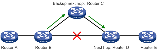
As shown in Figure 1, configure FRR on Router B by using a routing policy to specify a backup next hop. When the primary link fails, RIPng directs packets to the backup next hop. At the same time, RIPng calculates the shortest path based on the new network topology. Then, the device forwards packets over that path after network convergence.
Restrictions and guidelines for RIPng FRR
RIPng FRR is available only when the state of the primary link (with Layer 3 interfaces staying up) changes from bidirectional to unidirectional or down.
RIPng FRR is only effective for RIPng routes that are learned from directly connected neighbors.
Equal-cost routes do not support RIPng FRR.
Enabling RIPng FRR
1. Enter system view.
system-view
2. Configure a routing policy.
You must specify a next hop by using the apply ipv6 fast-reroute backup-interface command in a routing policy and specify the routing policy for FRR.
For more information about routing policy configuration, see "Configuring routing policies."
3. Enter RIPng view.
ripng [ process-id ] [ vpn-instance vpn-instance-name ]
4. Enable RIPng FRR.
fast-reroute route-policy route-policy-name
By default, RIPng FRR is disabled.
Enabling BFD for RIPng FRR
About BFD for RIPng FRR
By default, RIPng FRR does not use BFD to detect primary link failures. For quicker RIPng FRR, use BFD single-hop echo detection on the primary link of redundant links to detect link failure.
Procedure
1. Enter system view.
system-view
2. Configure the source IP address of BFD echo packets.
bfd echo-source-ipv6 ipv6-address
By default, the source IP address of BFD echo packets is not configured.
As a best practice, do not configure the source IP address on the same network segment as any local interfaces.
For more information about this command, see High Availability Command Reference.
3. Enter interface view.
interface interface-type interface-number
4. Enable BFD single-hop echo detection for RIPng FRR.
ripng primary-path-detect bfd echo
By default, BFD single-hop echo detection is disabled for RIPng FRR.
Enhancing RIPng security
Configuring zero field check for RIPng packets
About zero field check for RIPng packets
Some fields in the RIPng packet header must be zero. These fields are called zero fields. You can enable zero field check for incoming RIPng packets. If a zero field of a packet contains a non-zero value, RIPng does not process the packets. If you are certain that all packets are trustworthy, disable the zero field check to save CPU resources.
Procedure
1. Enter system view.
system-view
2. Enter RIPng view.
ripng [ process-id ] [ vpn-instance vpn-instance-name ]
3. Enable the zero field check for incoming RIPng packets.
checkzero
By default, zero field check for incoming RIPng packets is enabled.
Applying an IPsec profile
About IPsec profiles
To protect routing information and prevent attacks, you can configure RIPng to authenticate protocol packets by using an IPsec profile.
An IPsec profile contains inbound and outbound security parameter indexes (SPIs). RIPng compares the inbound SPI defined in the IPsec profile with the outbound SPI in the received packets. Two RIPng devices accept the packets from each other and establish a neighbor relationship only if the SPIs are the same and the relevant IPsec profiles match.
For more information about IPsec profiles, see Security Configuration Guide.
Restrictions and guidelines
You can apply an IPsec profile to a RIPng process or to an interface. If an interface and its process each have an IPsec profile, the IPsec profile applied to the interface takes effect.
Applying an IPsec profile to a process
1. Enter system view.
system-view
2. Enter RIPng view.
ripng [ process-id ] [ vpn-instance vpn-instance-name ]
3. Apply an IPsec profile to the process.
enable ipsec-profile profile-name
By default, no IPsec profile is applied.
Applying an IPsec profile to an interface
1. Enter system view.
system-view
2. Enter interface view.
interface interface-type interface-number
3. Apply an IPsec profile to the interface.
ripng ipsec-profile profile-name
By default, no IPsec profile is applied.
Display and maintenance commands for RIPng
Execute display commands in any view and reset commands in user view.
|
Task |
Command |
|
Display configuration information for a RIPng process. |
display ripng [ process-id ] |
|
Display RIPng GR information. |
display ripng [ process-id ] graceful-restart |
|
Display RIPng NSR information. |
display ripng [ process-id ] non-stop-routing |
|
Display routes in the RIPng database. |
display ripng process-id database [ ipv6-address prefix-length ] |
|
Display interface information for a RIPng process. |
display ripng process-id interface [ interface-type interface-number ] |
|
Display neighbor information for a RIPng process. |
display ripng process-id neighbor [ interface-type interface-number ] |
|
Display the routing information for a RIPng process. |
display ripng process-id route [ ipv6-address prefix-length [ verbose ] | peer ipv6-address | statistics ] |
|
Restart a RIPng process. |
reset ripng process-id process |
|
Clear statistics for a RIPng process. |
reset ripng process-id statistics |
RIPng configuration examples
Example: Configuring basic RIPng
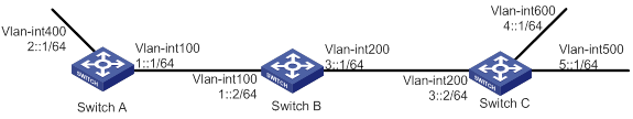
Network configuration
As shown in Figure 2, Switch A, Switch B, and Switch C run RIPng. Configure Switch B to filter the route 2::/64 learned from Switch A and to forward only the route 4::/64 to Switch A.
Procedure
1. Configure IPv6 addresses for the interfaces. (Details not shown.)
2. Configure basic RIPng settings:
# Configure Switch A.
<SwitchA> system-view
[SwitchA] ripng 1
[SwitchA-ripng-1] quit
[SwitchA] interface vlan-interface 100
[SwitchA-Vlan-interface100] ripng 1 enable
[SwitchA-Vlan-interface100] quit
[SwitchA] interface vlan-interface 400
[SwitchA-Vlan-interface400] ripng 1 enable
[SwitchA-Vlan-interface400] quit
# Configure Switch B.
<SwitchA> system-view
[SwitchA] ripng 1
[SwitchA-ripng-1] quit
[SwitchA] interface vlan-interface 100
[SwitchA-Vlan-interface100] ripng 1 enable
[SwitchA-Vlan-interface100] quit
[SwitchA] interface vlan-interface 400
[SwitchA-Vlan-interface400] ripng 1 enable
[SwitchA-Vlan-interface400] quit
# Configure Switch C.
<SwitchC> system-view
[SwitchC] ripng 1
[SwitchC-ripng-1] quit
[SwitchC] interface vlan-interface 200
[SwitchC-Vlan-interface200] ripng 1 enable
[SwitchC-Vlan-interface200] quit
[SwitchC] interface vlan-interface 500
[SwitchC-Vlan-interface500] ripng 1 enable
[SwitchC-Vlan-interface500] quit
[SwitchC] interface vlan-interface 600
[SwitchC-Vlan-interface600] ripng 1 enable
[SwitchC-Vlan-interface600] quit
# Display the RIPng routing table on Switch B.
[SwitchB] display ripng 1 route
Route Flags: A - Aging, S - Suppressed, G - Garbage-collect, D – Direct
O - Optimal, F - Flush to RIB
----------------------------------------------------------------
Peer FE80::20F:E2FF:FE23:82F5 on Vlan-interface100
Destination 2::/64,
via FE80::20F:E2FF:FE23:82F5, cost 1, tag 0, AOF, 6 secs
Peer FE80::20F:E2FF:FE00:100 on Vlan-interface200
Destination 4::/64,
via FE80::20F:E2FF:FE00:100, cost 1, tag 0, AOF, 11 secs
Destination 5::/64,
via FE80::20F:E2FF:FE00:100, cost 1, tag 0, AOF, 11
Local route
Destination 1::/64,
via ::, cost 0, tag 0, DOF
Destination 3::/64,
via ::, cost 0, tag 0, DOF
# Display the RIPng routing table on Switch A.
[SwitchA] display ripng 1 route
Route Flags: A - Aging, S - Suppressed, G - Garbage-collect, D – Direct
O - Optimal, F - Flush to RIB
----------------------------------------------------------------
Peer FE80::200:2FF:FE64:8904 on Vlan-interface100
Destination 3::/64,
via FE80::200:2FF:FE64:8904, cost 1, tag 0, AOF, 31 secs
Destination 4::/64,
via FE80::200:2FF:FE64:8904, cost 2, tag 0, AOF, 31 secs
Destination 5::/64,
via FE80::200:2FF:FE64:8904, cost 2, tag 0, AOF, 31 secs
Local route
Destination 2::/64,
via ::, cost 0, tag 0, DOF
Destination 1::/64,
via ::, cost 0, tag 0, DOF
3. Configure route filtering:
# Use IPv6 prefix lists on Switch B to filter received and redistributed routes.
[SwitchB] ipv6 prefix-list aaa permit 4:: 64
[SwitchB] ipv6 prefix-list bbb deny 2:: 64
[SwitchB] ipv6 prefix-list bbb permit :: 0 less-equal 128
[SwitchB] ripng 1
[SwitchB-ripng-1] filter-policy prefix-list aaa export
[SwitchB-ripng-1] filter-policy prefix-list bbb import
[SwitchB-ripng-1] quit
# Display RIPng routing tables on Switch B and Switch A.
[SwitchB] display ripng 1 route
Route Flags: A - Aging, S - Suppressed, G - Garbage-collect, D – Direct
O - Optimal, F - Flush to RIB
----------------------------------------------------------------
Peer FE80::1:100 on Vlan-interface100
Peer FE80::3:200 on Vlan-interface200
Destination 4::/64,
via FE80::2:200, cost 1, tag 0, AOF, 11 secs
Destination 5::/64,
via FE80::2:200, cost 1, tag 0, AOF, 11 secs
Local route
Destination 1::/64,
via ::, cost 0, tag 0, DOF
Destination 3::/64,
via ::, cost 0, tag 0, DOF
[SwitchA] display ripng 1 route
Route Flags: A - Aging, S - Suppressed, G - Garbage-collect, D – Direct
O - Optimal, F - Flush to RIB
----------------------------------------------------------------
Peer FE80::2:100 on Vlan-interface100
Destination 4::/64,
via FE80::1:100, cost 2, tag 0, AOF, 2 secs
Example: Configuring RIPng route redistribution
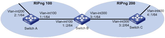
Network configuration
As shown in Figure 3, Switch B communicates with Switch A through RIPng 100 and with Switch C through RIPng 200.
Configure route redistribution on Switch B, so the two RIPng processes can redistribute routes from each other.
Procedure
1. Configure IPv6 addresses for the interfaces. (Details not shown.)
2. Configure basic RIPng settings:
# Enable RIPng 100 on Switch A.
<SwitchA> system-view
[SwitchA] ripng 100
[SwitchA-ripng-100] quit
[SwitchA] interface vlan-interface 100
[SwitchA-Vlan-interface100] ripng 100 enable
[SwitchA-Vlan-interface100] quit
[SwitchA] interface vlan-interface 200
[SwitchA-Vlan-interface200] ripng 100 enable
[SwitchA-Vlan-interface200] quit
# Enable RIPng 100 and RIPng 200 on Switch B.
<SwitchB> system-view
[SwitchB] ripng 100
[SwitchB-ripng-100] quit
[SwitchB] interface vlan-interface 100
[SwitchB-Vlan-interface100] ripng 100 enable
[SwitchB-Vlan-interface100] quit
[SwitchB] ripng 200
[SwitchB-ripng-200] quit
[SwitchB] interface vlan-interface 300
[SwitchB-Vlan-interface300] ripng 200 enable
[SwitchB-Vlan-interface300] quit
# Enable RIPng 200 on Switch C.
<SwitchC> system-view
[SwitchC] ripng 200
[SwitchC] interface vlan-interface 300
[SwitchC-Vlan-interface300] ripng 200 enable
[SwitchC-Vlan-interface300] quit
[SwitchC] interface vlan-interface 400
[SwitchC-Vlan-interface400] ripng 200 enable
[SwitchC-Vlan-interface400] quit
# Display the routing table on Switch A.
[SwitchA] display ipv6 routing-table
Destinations : 7 Routes : 7
Destination: ::1/128 Protocol : Direct
NextHop : ::1 Preference: 0
Interface : InLoop0 Cost : 0
Destination: 1::/64 Protocol : Direct
NextHop : :: Preference: 0
Interface : Vlan100 Cost : 0
Destination: 1::1/128 Protocol : Direct
NextHop : ::1 Preference: 0
Interface : InLoop0 Cost : 0
Destination: 2::/64 Protocol : Direct
NextHop : :: Preference: 0
Interface : Vlan200 Cost : 0
Destination: 2::1/128 Protocol : Direct
NextHop : ::1 Preference: 0
Interface : InLoop0 Cost : 0
Destination: FE80::/10 Protocol : Direct
NextHop : :: Preference: 0
Interface : NULL0 Cost : 0
Destination: FF00::/8 Protocol : Direct
NextHop : :: Preference: 0
Interface : NULL0 Cost : 0
3. Configure RIPng route redistribution:
# Configure route redistribution between the two RIPng processes on Switch B.
[SwitchB] ripng 100
[SwitchB-ripng-100] import-route ripng 200
[SwitchB-ripng-100] quit
[SwitchB] ripng 200
[SwitchB-ripng-200] import-route ripng 100
[SwitchB-ripng-200] quit
# Display the routing table on Switch A.
[SwitchA] display ipv6 routing-table
Destinations : 8 Routes : 8
Destination: ::1/128 Protocol : Direct
NextHop : ::1 Preference: 0
Interface : InLoop0 Cost : 0
Destination: 1::/64 Protocol : Direct
NextHop : :: Preference: 0
Interface : Vlan100 Cost : 0
Destination: 1::1/128 Protocol : Direct
NextHop : ::1 Preference: 0
Interface : InLoop0 Cost : 0
Destination: 2::/64 Protocol : Direct
NextHop : :: Preference: 0
Interface : Vlan200 Cost : 0
Destination: 2::1/128 Protocol : Direct
NextHop : ::1 Preference: 0
Interface : InLoop0 Cost : 0
Destination: 4::/64 Protocol : RIPng
NextHop : FE80::200:BFF:FE01:1C02 Preference: 100
Interface : Vlan100 Cost : 1
Destination: FE80::/10 Protocol : Direct
NextHop : :: Preference: 0
Interface : NULL0 Cost : 0
Destination: FF00::/8 Protocol : Direct
NextHop : :: Preference: 0
Interface : NULL0 Cost : 0
Example: Configuring RIPng GR
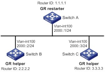
Network configuration
As shown in Figure 4, Switch A, Switch B, and Switch C learn IPv6 routing information through RIPng.
Configure Switch A as the GR restarter. Configure Switch B and Switch C as the GR helpers to synchronize their routing tables with Switch A by using GR.
Procedure
1. Configure IPv6 addresses for the interfaces. (Details not shown.)
2. Configure RIPng on the switches to ensure the following: (Details not shown.)
¡ Switch A, Switch B, and Switch C can communicate with each other at Layer 3.
¡ Dynamic route update can be implemented among them with RIPng.
3. Enable RIPng GR on Switch A.
<SwitchA> system-view
[SwitchA] ripng 1
[SwitchA-ripng-1] graceful-restart
Verifying the configuration
# Restart RIPng or trigger an active/standby switchover, and then display GR status on Switch A.
<SwitchA> display ripng 1 graceful-restart
RIPng process: 1
Graceful Restart capability : Enabled
Current GR state : Normal
Graceful Restart period : 60 seconds
Graceful Restart remaining time: 0 seconds
Example: Configuring RIPng NSR
Network configuration
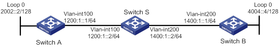
As shown in Figure 5, Switch S, Switch A, and Switch B learn IPv6 routing information through RIPng.
Enable RIPng NSR on Switch S to ensure correct routing when an active/standby switchover occurs on Switch S.
Procedure
1. Configure IPv6 addresses for the interfaces. (Details not shown.)
2. Configure RIPng on the switches to ensure the following: (Details not shown.)
¡ Switch S, Switch A, and Switch B can communicate with each other at Layer 3.
¡ Dynamic route update can be implemented among them with RIPng.
3. Enable RIPng NSR on Switch S.
<SwitchS> system-view
[SwitchS] ripng 1
[SwitchS-ripng-1] non-stop-routing
[SwitchS-ripng-1] quit
Verifying the configuration
# Perform an active/standby switchover on Switch S.
[SwitchS] placement reoptimize
Predicted changes to the placement
Program Current location New location
---------------------------------------------------------------------
lb 0/0 0/0
lsm 0/0 0/0
slsp 0/0 0/0
rib6 0/0 0/0
routepolicy 0/0 0/0
rib 0/0 0/0
staticroute6 0/0 0/0
staticroute 0/0 0/0
eviisis 0/0 0/0
ospf 0/0 1/0
Continue? [y/n]:y
Re-optimization of the placement start. You will be notified on completion
Re-optimization of the placement complete. Use 'display placement' to view the new placement
# During the switchover period, display RIPng neighbors on Switch A to verify the neighbor relationship between Switch A and Switch S.
[SwitchA] display ripng 1 neighbor
Neighbor Address: FE80::AE45:5CE7:422E:2867
Interface : Vlan-interface100
Version : RIPng version 1 Last update: 00h00m23s
Bad packets: 0 Bad routes : 0
# Display RIPng routes on Switch A to verify if Switch A has a route to the loopback interface on Switch B.
[SwitchA] display ripng 1 route
Route Flags: A - Aging, S - Suppressed, G - Garbage-collect, D - Direct
O - Optimal, F - Flush to RIB
----------------------------------------------------------------
Peer FE80::AE45:5CE7:422E:2867 on Vlan-interface100
Destination 1400:1::/64,
via FE80::AE45:5CE7:422E:2867, cost 1, tag 0, AOF, 1 secs
Destination 4004::4/128,
via FE80::AE45:5CE7:422E:2867, cost 2, tag 0, AOF, 1 secs
Local route
Destination 2002::2/128,
via ::, cost 0, tag 0, DOF
Destination 1200:1::/64,
via ::, cost 0, tag 0, DOF
# Display RIPng neighbors on Switch B to verify the neighbor relationship between Switch B and Switch S.
[SwitchB] display ripng 1 neighbor
Neighbor Address: FE80::20C:29FF:FECE:6277
Interface : Vlan-interface200
Version : RIPng version 1 Last update: 00h00m18s
Bad packets: 0 Bad routes : 0
# Display RIPng routes on Switch B to verify if Switch B has a route to the loopback interface on Switch A.
[SwitchB] display ripng 1 route
Route Flags: A - Aging, S - Suppressed, G - Garbage-collect, D - Direct
O - Optimal, F - Flush to RIB
----------------------------------------------------------------
Peer FE80::20C:29FF:FECE:6277 on Vlan-interface200
Destination 2002::2/128,
via FE80::20C:29FF:FECE:6277, cost 2, tag 0, AOF, 24 secs
Destination 1200:1::/64,
via FE80::20C:29FF:FECE:6277, cost 1, tag 0, AOF, 24 secs
Local route
Destination 4004::4/128,
via ::, cost 0, tag 0, DOF
Destination 1400:1::/64,
via ::, cost 0, tag 0, DOF
The output shows the following when an active/standby switchover occurs on Switch S:
· The neighbor relationships and routing information on Switch A and Switch B have not changed.
· The traffic from Switch A to Switch B has not been impacted.
Example: Configuring RIPng FRR
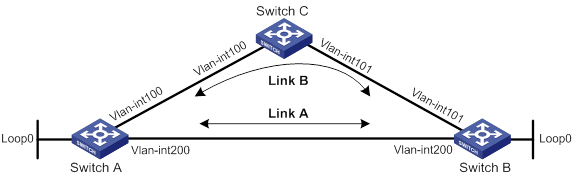
Network configuration
As shown in Figure 6, Switch A, Switch B, and Switch C run RIPng. Configure RIPng FRR so that when Link A becomes unidirectional, traffic can be switched to Link B immediately.
|
Device |
Interface |
IP address |
|
Switch A |
VLAN-interface 100 |
1::1/64 |
|
Switch A |
VLAN-interface 200 |
2::1/64 |
|
Switch A |
Loopback 0 |
10::1/128 |
|
Switch B |
VLAN-interface 101 |
3::1/64 |
|
Switch B |
VLAN-interface 200 |
2::2/64 |
|
Switch B |
Loopback 0 |
20::1/128 |
|
Switch C |
VLAN-interface 100 |
1::2/64 |
|
Switch C |
VLAN-interface 101 |
3::2/64 |
Procedure
1. Configure IPv6 addresses for the interfaces on the switches. (Details not shown.)
2. Configure RIPng on the switches to make sure Switch A, Switch B, and Switch C can communicate with each other at Layer 3. (Details not shown.)
3. Configure RIPng FRR:
# Configure Switch A.
<SwitchA> system-view
[SwitchA] ipv6 prefix-list abc index 10 permit 20::1 128
[SwitchA] route-policy frr permit node 10
[SwitchA-route-policy-frr-10] if-match ipv6 address prefix-list abc
[SwitchA-route-policy-frr-10] apply ipv6 fast-reroute backup-interface vlan-interface 100 backup-nexthop 1::2
[SwitchA-route-policy-frr-10] quit
[SwitchA] ripng 1
[SwitchA-ripng-1] fast-reroute route-policy frr
[SwitchA-ripng-1] quit
# Configure Switch B.
<SwitchB> system-view
[SwitchB] ipv6 prefix-list abc index 10 permit 10::1 128
[SwitchB] route-policy frr permit node 10
[SwitchB-route-policy-frr-10] if-match ipv6 address prefix-list abc
[SwitchB-route-policy-frr-10] apply ipv6 fast-reroute backup-interface vlan-interface 101 backup-nexthop 3::2
[SwitchB-route-policy-frr-10] quit
[SwitchB] ripng 1
[SwitchB-ripng-1] fast-reroute route-policy frr
[SwitchB-ripng-1] quit
Verifying the configuration
# Display the route 20::1/128 on Switch A to view the backup next hop information.
[SwitchA] display ipv6 routing-table 20::1 128 verbose
Summary count : 1
Destination: 20::1/128
Protocol: RIPng
Process ID: 1
SubProtID: 0x0 Age: 00h17m42s
Cost: 1 Preference: 100
IpPre: N/A QosLocalID: N/A
Tag: 0 State: Inactive Adv
OrigTblID: 0x0 OrigVrf: default-vrf
TableID: 0xa OrigAs: 0
NibID: 0x22000003 LastAs: 0
AttrID: 0xffffffff Neighbor: FE80::34CD:9FF:FE2F:D02
Flags: 0x41 OrigNextHop: FE80::34CD:9FF:FE2F:D02
Label: NULL RealNextHop: FE80::34CD:9FF:FE2F:D02
BkLabel: NULL BkNextHop: FE80::7685:45FF:FEAD:102
Tunnel ID: Invalid Interface: Vlan-interface200
BkTunnel ID: Invalid BkInterface: Vlan-interface100
FtnIndex: 0x0 TrafficIndex: N/A
Connector: N/A PathID: 0x0
# Display the route 10::1/128 on Switch B to view the backup next hop information.
[SwitchB] display ipv6 routing-table 10::1 128 verbose
Summary count : 1
Destination: 10::1/128
Protocol: RIPng
Process ID: 1
SubProtID: 0x0 Age: 00h22m34s
Cost: 1 Preference: 100
IpPre: N/A QosLocalID: N/A
Tag: 0 State: Inactive Adv
OrigTblID: 0x0 OrigVrf: default-vrf
TableID: 0xa OrigAs: 0
NibID: 0x22000001 LastAs: 0
AttrID: 0xffffffff Neighbor: FE80::34CC:E8FF:FE5B:C02
Flags: 0x41 OrigNextHop: FE80::34CC:E8FF:FE5B:C02
Label: NULL RealNextHop: FE80::34CC:E8FF:FE5B:C02
BkLabel: NULL BkNextHop: FE80::7685:45FF:FEAD:102
Tunnel ID: Invalid Interface: Vlan-interface200
BkTunnel ID: Invalid BkInterface: Vlan-interface101
FtnIndex: 0x0 TrafficIndex: N/A
Connector: N/A PathID: 0x0
Example: Using an IPsec profile to protect RIPng
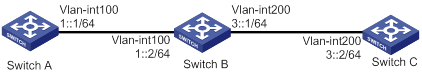
Network configuration
As shown in Figure 7, configure RIPng on the switches, and configure IPsec profiles on the switches to authenticate and encrypt protocol packets.
Procedure
1. Configure IPv6 addresses for the interfaces. (Details not shown.)
2. Configure basic RIPng settings:
# Configure Switch A.
<SwitchA> system-view
[SwitchA] ripng 1
[SwitchA-ripng-1] quit
[SwitchA] interface vlan-interface 100
[SwitchA-Vlan-interface100] ripng 1 enable
[SwitchA-Vlan-interface100] quit
# Configure Switch B.
<SwitchB> system-view
[SwitchB] ripng 1
[SwitchB-ripng-1] quit
[SwitchB] interface vlan-interface 200
[SwitchB-Vlan-interface200] ripng 1 enable
[SwitchB-Vlan-interface200] quit
[SwitchB] interface vlan-interface 100
[SwitchB-Vlan-interface100] ripng 1 enable
[SwitchB-Vlan-interface100] quit
# Configure Switch C.
<SwitchC> system-view
[SwitchC] ripng 1
[SwitchC-ripng-1] quit
[SwitchC] interface vlan-interface 200
[SwitchC-Vlan-interface200] ripng 1 enable
[SwitchC-Vlan-interface200] quit
3. Configure RIPng IPsec profiles:
¡ On Switch A:
# Create an IPsec transform set named protrf1.
[SwitchA] ipsec transform-set protrf1
# Specify the ESP encryption and authentication algorithms.
[SwitchA-ipsec-transform-set-protrf1] esp encryption-algorithm 3des-cbc
[SwitchA-ipsec-transform-set-protrf1] esp authentication-algorithm md5
# Specify transport mode for encapsulation.
[SwitchA-ipsec-transform-set-protrf1] encapsulation-mode transport
[SwitchA-ipsec-transform-set-protrf1] quit
# Create a manual IPsec profile named profile001.
[SwitchA] ipsec profile profile001 manual
# Reference IPsec transform set protrf1.
[SwitchA-ipsec-profile-profile001-manual] transform-set protrf1
# Configure the inbound and outbound SPIs for ESP.
[SwitchA-ipsec-profile-profile001-manual] sa spi inbound esp 256
[SwitchA-ipsec-profile-profile001-manual] sa spi outbound esp 256
# Configure the inbound and outbound SA keys for ESP.
[SwitchA-ipsec-profile-profile001-manual] sa string-key inbound esp simple abc
[SwitchA-ipsec-profile-profile001-manual] sa string-key outbound esp simple abc
[SwitchA-ipsec-profile-profile001-manual] quit
¡ On Switch B:
# Create an IPsec transform set named protrf1.
[SwitchB] ipsec transform-set protrf1
# Specify the ESP encryption and authentication algorithms.
[SwitchB-ipsec-transform-set-protrf1] esp encryption-algorithm 3des-cbc
[SwitchB-ipsec-transform-set-protrf1] esp authentication-algorithm md5
# Specify transport mode for encapsulation.
[SwitchB-ipsec-transform-set-protrf1] encapsulation-mode transport
[SwitchB-ipsec-transform-set-protrf1] quit
# Create a manual IPsec profile named profile001.
[SwitchB] ipsec profile profile001 manual
# Reference IPsec transform set protrf1.
[SwitchB-ipsec-profile-profile001-manual] transform-set protrf1
# Configure the inbound and outbound SPIs for ESP.
[SwitchB-ipsec-profile-profile001-manual] sa spi inbound esp 256
[SwitchB-ipsec-profile-profile001-manual] sa spi outbound esp 256
# Configure the inbound and outbound SA keys for ESP.
[SwitchB-ipsec-profile-profile001-manual] sa string-key inbound esp simple abc
[SwitchB-ipsec-profile-profile001-manual] sa string-key outbound esp simple abc
[SwitchB-ipsec-profile-profile001-manual] quit
¡ On Switch C:
# Create an IPsec transform set named protrf1.
[SwitchC] ipsec transform-set protrf1
# Specify the ESP encryption and authentication algorithms.
[SwitchC-ipsec-transform-set-protrf1] esp encryption-algorithm 3des-cbc
[SwitchC-ipsec-transform-set-protrf1] esp authentication-algorithm md5
# Specify transport mode for encapsulation.
[SwitchC-ipsec-transform-set-protrf1] encapsulation-mode transport
[SwitchC-ipsec-transform-set-protrf1] quit
# Create a manual IPsec profile named profile001.
[SwitchC] ipsec profile profile001 manual
# Reference IPsec transform set protrf1.
[SwitchC-ipsec-profile-profile001-manual] transform-set protrf1
# Configure the inbound and outbound SPIs for ESP.
[SwitchC-ipsec-profile-profile001-manual] sa spi inbound esp 256
[SwitchC-ipsec-profile-profile001-manual] sa spi outbound esp 256
# Configure the inbound and outbound SA keys for ESP.
[SwitchC-ipsec-profile-profile001-manual] sa string-key inbound esp simple abc
[SwitchC-ipsec-profile-profile001-manual] sa string-key outbound esp simple abc
[SwitchC-ipsec-profile-profile001-manual] quit
4. Apply the IPsec profiles to the RIPng process on each device:
¡ On Switch A:
[SwitchA] ripng 1
[SwitchA-ripng-1] enable ipsec-profile profile001
[SwitchA-ripng-1] quit
¡ On Switch B:
[SwitchB] ripng 1
[SwitchB-ripng-1] enable ipsec-profile profile001
[SwitchB-ripng-1] quit
¡ On Switch C:
[SwitchC] ripng 1
[SwitchC-ripng-1] enable ipsec-profile profile001
[SwitchC-ripng-1] quit
Verifying the configuration
# Verify that the RIPng packets between Switches A, B and C are protected by IPsec. (Details not shown.)