- Table of Contents
-
- 03-Layer 2-LAN Switching Configuration Guide
- 00-Preface
- 01-Ethernet interface configuration
- 02-Loopback, null, and inloopback interface configuration
- 03-Bulk interface configuration
- 04-MAC address table configuration
- 05-Ethernet link aggregation configuration
- 06-Port isolation configuration
- 07-Spanning tree configuration
- 08-Loop detection configuration
- 09-VLAN configuration
- 10-MVRP configuration
- 11-QinQ configuration
- 12-VLAN mapping configuration
- 13-LLDP configuration
- 14-L2PT configuration
- Related Documents
-
| Title | Size | Download |
|---|---|---|
| 10-MVRP configuration | 159.68 KB |
Contents
Restrictions and guidelines: MVRP configuration
Setting an MVRP registration mode
Configuring MVRP
About MVRP
Multiple Registration Protocol (MRP) is an attribute registration protocol used to transmit attribute values. Multiple VLAN Registration Protocol (MVRP) is a typical MRP application. It synchronizes VLAN information among devices and greatly reduces the workload of network administrators.
MRP implementation
An MRP-enabled port is called an MRP participant. An MVRP-enabled port is called an MVRP participant.
As shown in Figure 1, an MRP participant sends declarations and withdrawals to notify other participants to register and deregister its attribute values. It also registers and deregisters the attribute values of other participants according to the received declarations and withdrawals. MRP rapidly propagates the configuration information of an MRP participant throughout the LAN.
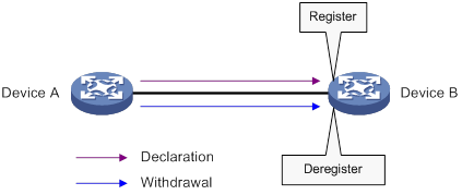
For example, MRP registers and deregisters VLAN attributes as follows:
· When a port receives a declaration for a VLAN, the port registers the VLAN and joins the VLAN.
· When a port receives a withdrawal for a VLAN, the port deregisters the VLAN and leaves the VLAN.
MRP allows devices in the same LAN to transmit attribute values on a per MSTI basis. Figure 1 shows a simple MRP implementation on an MSTI. In a network with multiple MSTIs, MRP performs attribute registration and deregistration on a per MSTI basis. For more information about MSTIs, see "Configuring spanning tree protocols."
MRP messages
MRP messages include the following types:
· Declaration—Includes Join and New messages.
· Withdrawal—Includes Leave and LeaveAll messages.
Join message
An MRP participant sends a Join message to request the peer participant to register attributes in the Join message.
When receiving a Join message from the peer participant, an MRP participant performs the following tasks:
· Registers the attributes in the Join message.
· Propagates the Join message to all other participants on the device.
After receiving the Join message, other participants send the Join message to their respective peer participants.
Join messages sent from a local participant to its peer participant include the following types:
· JoinEmpty—Declares an unregistered attribute. For example, when an MRP participant joins an unregistered static VLAN, it sends a JoinEmpty message.
VLANs created manually and locally are called static VLANs. VLANs learned through MRP are called dynamic VLANs.
· JoinIn—Declares a registered attribute. A JoinIn message is used in one of the following situations:
¡ An MRP participant joins an existing static VLAN and sends a JoinIn message after registering the VLAN.
¡ The MRP participant receives a Join message propagated by another participant on the device and sends a JoinIn message after registering the VLAN.
New message
Similar to a Join message, a New message enables MRP participants to register attributes.
When the MSTP topology changes, an MRP participant sends a New message to the peer participant to declare the topology change.
Upon receiving a New message from the peer participant, an MRP participant performs the following tasks:
· Registers the attributes in the message.
· Propagates the New message to all other participants on the device.
After receiving the New message, other participants send the New message to their respective peer participants.
Leave message
An MRP participant sends a Leave message to the peer participant when it wants the peer participant to deregister attributes that it has deregistered.
When the peer participant receives the Leave message, it performs the following tasks:
· Deregisters the attribute in the Leave message.
· Propagates the Leave message to all other participants on the device.
After a participant on the device receives the Leave message, it determines whether to send the Leave message to its peer participant depending on the attribute status on the device.
· If the VLAN in the Leave message is a dynamic VLAN not registered by any participants on the device, both of the following events occur:
¡ The VLAN is deleted on the device.
¡ The participant sends the Leave message to its peer participant.
· If the VLAN in the Leave message is a static VLAN, the participant will not send the Leave message to its peer participant.
LeaveAll message
Each MRP participant starts its LeaveAll timer when starting up. When the timer expires, the MRP participant sends LeaveAll messages to the peer participant.
Upon sending or receiving a LeaveAll message, the local participant starts the Leave timer. The local participant determines whether to send a Join message depending on its attribute status. A participant can re-register the attributes in the received Join message before the Leave timer expires.
When the Leave timer expires, a participant deregisters all attributes that have not been re-registered to periodically clear useless attributes in the network.
MRP timers
MRP uses the following timers to control message transmission.
Periodic timer
The Periodic timer controls the transmission of MRP messages. An MRP participant starts its own Periodic timer upon startup, and stores MRP messages to be sent before the Periodic timer expires. When the Periodic timer expires, MRP sends stored MRP messages in as few MRP frames as possible and restarts the Periodic timer. This mechanism reduces the number of MRP frames sent.
You can enable or disable the Periodic timer. When the Periodic timer is disabled, MRP does not periodically send MRP messages. Instead, an MRP participant sends MRP messages when the LeaveAll timer expires or the participant receives a LeaveAll message from the peer participant.
Join timer
The Join timer controls the transmission of Join messages. An MRP participant starts the Join timer after sending a Join message to the peer participant. Before the Join timer expires, the participant does not resend the Join message when the following conditions exist:
· The participant receives a JoinIn message from the peer participant.
· The received JoinIn message has the same attributes as the sent Join message.
When both the Join timer and the Periodic timer expire, the participant resends the Join message.
Leave timer
The Leave timer controls the deregistration of attributes.
An MRP participant starts the Leave timer in one of the following conditions:
· The participant receives a Leave message from its peer participant.
· The participant receives or sends a LeaveAll message.
The MRP participant does not deregister the attributes in the Leave or LeaveAll message if the following conditions exist:
· The participant receives a Join message before the Leave timer expires.
· The Join message includes the attributes that have been encapsulated in the Leave or LeaveAll message.
If the participant does not receive a Join message for these attributes before the Leave timer expires, MRP deregisters the attributes.
LeaveAll timer
After startup, an MRP participant starts its own LeaveAll timer. When the LeaveAll timer expires, the MRP participant sends out a LeaveAll message and restarts the LeaveAll timer.
Upon receiving the LeaveAll message, other participants restart their LeaveAll timer. The value of the LeaveAll timer is randomly selected between the LeaveAll timer and 1.5 times the LeaveAll timer. This mechanism provides the following benefits:
· Effectively reduces the number of LeaveAll messages in the network.
· Prevents the LeaveAll timer of a particular participant from always expiring first.
MVRP registration modes
VLAN information propagated by MVRP includes dynamic VLAN information from other devices and local static VLAN information.
Based on how an MVRP participant handles registration of dynamic VLANs, MVRP has the following registration modes:
· Normal—An MVRP participant in normal registration mode registers and deregisters dynamic VLANs.
· Fixed—An MVRP participant in fixed registration mode disables deregistering dynamic VLANs and drops received MVRP frames. The MVRP participant does not deregister dynamic VLANs or register new dynamic VLANs.
· Forbidden—An MVRP participant in forbidden registration mode disables registering dynamic VLANs and drops received MVRP frames. The MVRP participant does not register new dynamic VLANs or re-register a deregistered dynamic VLAN.
Protocols and standards
IEEE 802.1ak, IEEE Standard for Local and Metropolitan Area Networks: Virtual Bridged Local Area Networks – Amendment 07: Multiple Registration Protocol
Restrictions and guidelines: MVRP configuration
When you configure MVRP, follow these restrictions and guidelines:
· MVRP can work with STP, RSTP, or MSTP. Ports blocked by STP, RSTP, or MSTP can receive and send MVRP frames. Do not configure MVRP with other link layer topology protocols, such as PVST, RRPP, and Smart Link.
For more information about STP, RSTP, MSTP, and PVST, see "Configuring spanning tree protocols." For more information about RRPP and Smart Link, see High Availability Configuration Guide.
· Do not configure both MVRP and remote port mirroring on a port. Otherwise, MVRP might register the remote probe VLAN with incorrect ports, which would cause the monitor port to receive undesired copies. For more information about port mirroring, see Network Management and Monitoring Configuration Guide.
· Enabling MVRP on a Layer 2 aggregate interface takes effect on the aggregate interface and all Selected member ports in the link aggregation group.
· MVRP configuration made on an aggregation group member port takes effect only after the port is removed from the aggregation group.
MVRP tasks at a glance
To configure MVRP, perform the following tasks:
2. Setting an MVRP registration mode
3. (Optional.) Setting MRP timers
4. (Optional.) Enabling GVRP compatibility
Prerequisites
Before you configure MVRP, complete the following tasks:
· Map each MSTI used by MVRP to an existing VLAN on each device in the network.
· Set the port link type of MVRP participants to trunk because MVRP takes effect only on trunk ports. For more information about trunk ports, see "Configuring VLANs."
Enabling MVRP
1. Enter system view.
system-view
2. Enable MVRP globally.
mvrp global enable
By default, MVRP is globally disabled.
For MVRP to take effect on a port, enable MVRP both on the port and globally.
3. Enter Layer 2 Ethernet interface view or Layer 2 aggregate interface view.
interface interface-type interface-number
4. Configure the port as a trunk port.
port link-type trunk
By default, each port is an access port. For more information about the port link-type trunk command, see Layer 2—LAN Switching Command Reference.
5. Configure the trunk port to permit the specified VLANs.
port trunk permit vlan { vlan-id-list | all }
By default, a trunk port permits only VLAN 1.
Make sure the trunk port permits all registered VLANs.
For more information about the port trunk permit vlan command, see Layer 2—LAN Switching Command Reference.
6. Enable MVRP on the port.
mvrp enable
By default, MVRP is disabled on a port.
Setting an MVRP registration mode
1. Enter system view.
system-view
2. Enter Layer 2 Ethernet interface view or Layer 2 aggregate interface view.
interface interface-type interface-number
3. Set an MVRP registration mode for the port.
mvrp registration { fixed | forbidden | normal }
The default setting is normal registration mode.
Setting MRP timers
Restrictions and guidelines
When you set MVRP timers, follow these restrictions and guidelines:
· Follow the value range requirements for Join, Leave, and LeaveAll timers and their dependencies as described in Table 1. If you set a timer to a value beyond the allowed value range, your configuration fails. You can set a timer by tuning the value of any other timer. The value of each timer must be an integer multiple of 20 centiseconds.
Table 1 Dependencies of the Join, Leave, and LeaveAll timers
|
Timer |
Lower limit |
Upper limit |
|
Join |
20 centiseconds |
Half the Leave timer |
|
Leave |
Twice the Join timer |
LeaveAll timer |
|
LeaveAll |
Leave timer on each port |
32760 centiseconds |
· To avoid frequent VLAN registrations and deregistrations, use the same MRP timers throughout the network.
· Each port maintains its own Periodic, Join, and LeaveAll timers, and each attribute of a port maintains a Leave timer.
· As a best practice, restore the timers in the order of Join, Leave, and LeaveAll when you restore these timers to their default values.
· You can restore the Periodic timer to its default value at any time.
Procedure
1. Enter system view.
system-view
2. Enter Layer 2 Ethernet interface view or Layer 2 aggregate interface view.
interface interface-type interface-number
3. Set the LeaveAll timer.
mrp timer leaveall timer-value
The default setting is 1000 centiseconds.
4. Set the Join timer.
mrp timer join timer-value
The default setting is 20 centiseconds.
5. Set the Leave timer.
mrp timer leave timer-value
The default setting is 60 centiseconds.
6. Set the Periodic timer.
mrp timer periodic timer-value
The default setting is 100 centiseconds.
Enabling GVRP compatibility
About GVRP compatibility
Perform this task to enable the device to receive and send both MVRP and GVRP frames when the peer device supports GVRP. For more information about GVRP, see the IEEE 802.1Q standard.
Restrictions and guidelines
When you enable GVRP compatibility, follow these restrictions and guidelines:
· GVRP compatibility enables MVRP to work with STP or RSTP, but not MSTP.
· When the system is busy, disable the Period timer to prevent the participant from frequently registering or deregistering attributes.
Procedure
1. Enter system view.
system-view
2. Enable GVRP compatibility.
mvrp gvrp-compliance enable
By default, GVRP compatibility is disabled.
Display and maintenance commands for MVRP
Execute display commands in any view and reset commands in user view.
|
Task |
Command |
|
Display MVRP running status. |
display mvrp running-status [ interface interface-list ] |
|
Display the MVRP state of a port in a VLAN. |
display mvrp state interface interface-type interface-number vlan vlan-id |
|
Display MVRP statistics. |
display mvrp statistics [ interface interface-list ] |
|
Clear MVRP statistics. |
reset mvrp statistics [ interface interface-list ] |
MVRP configuration examples
Example: Configuring basic MVRP functions
Network configuration
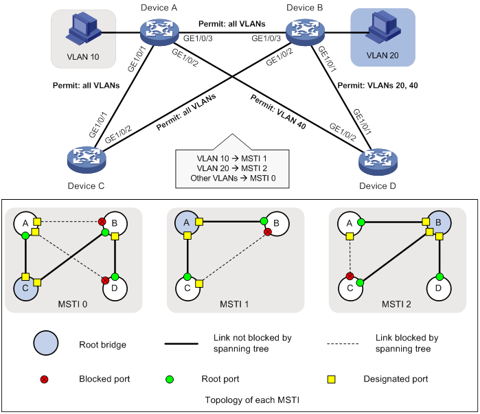
As shown in Figure 2:
· Create VLAN 10 on Device A and VLAN 20 on Device B.
· Configure MSTP, map VLAN 10 to MSTI 1, map VLAN 20 to MSTI 2, and map the other VLANs to MSTI 0.
Configure MVRP on Device A, Device B, Device C, and Device D to meet the following requirements:
· The devices can register and deregister dynamic VLANs.
· The devices can keep identical VLAN configurations for each MSTI.
Procedure
1. Configure Device A:
# Enter MST region view.
<DeviceA> system-view
[DeviceA] stp region-configuration
# Configure the MST region name, VLAN-to-instance mappings, and revision level.
[DeviceA-mst-region] region-name example
[DeviceA-mst-region] instance 1 vlan 10
[DeviceA-mst-region] instance 2 vlan 20
[DeviceA-mst-region] revision-level 0
# Manually activate the MST region configuration.
[DeviceA-mst-region] active region-configuration
[DeviceA-mst-region] quit
# Configure Device A as the primary root bridge of MSTI 1.
[DeviceA] stp instance 1 root primary
# Globally enable the spanning tree feature.
[DeviceA] stp global enable
# Globally enable MVRP.
[DeviceA] mvrp global enable
# Configure GigabitEthernet 1/0/1 as a trunk port, and configure it to permit all VLANs.
[DeviceA] interface gigabitethernet 1/0/1
[DeviceA-GigabitEthernet1/0/1] port link-type trunk
[DeviceA-GigabitEthernet1/0/1] port trunk permit vlan all
# Enable MVRP on GigabitEthernet 1/0/1.
[DeviceA-GigabitEthernet1/0/1] mvrp enable
[DeviceA-GigabitEthernet1/0/1] quit
# Configure GigabitEthernet 1/0/2 as a trunk port, and configure it to permit VLAN 40.
[DeviceA] interface gigabitethernet 1/0/2
[DeviceA-GigabitEthernet1/0/2] port link-type trunk
[DeviceA-GigabitEthernet1/0/2] port trunk permit vlan 40
# Enable MVRP on GigabitEthernet 1/0/2.
[DeviceA-GigabitEthernet1/0/2] mvrp enable
[DeviceA-GigabitEthernet1/0/2] quit
# Configure GigabitEthernet 1/0/3 as a trunk port, and configure it to permit all VLANs.
[DeviceA] interface gigabitethernet 1/0/3
[DeviceA-GigabitEthernet1/0/3] port link-type trunk
[DeviceA-GigabitEthernet1/0/3] port trunk permit vlan all
# Enable MVRP on GigabitEthernet 1/0/3.
[DeviceA-GigabitEthernet1/0/3] mvrp enable
[DeviceA-GigabitEthernet1/0/3] quit
# Create VLAN 10.
[DeviceA] vlan 10
[DeviceA-vlan10] quit
2. Configure Device B:
# Enter MST region view.
<DeviceB> system-view
[DeviceB] stp region-configuration
# Configure the MST region name, VLAN-to-instance mappings, and revision level.
[DeviceB-mst-region] region-name example
[DeviceB-mst-region] instance 1 vlan 10
[DeviceB-mst-region] instance 2 vlan 20
[DeviceB-mst-region] revision-level 0
# Manually activate the MST region configuration.
[DeviceB-mst-region] active region-configuration
[DeviceB-mst-region] quit
# Configure Device B as the primary root bridge of MSTI 2.
[DeviceB] stp instance 2 root primary
# Globally enable the spanning tree feature.
[DeviceB] stp global enable
# Globally enable MVRP.
[DeviceB] mvrp global enable
# Configure GigabitEthernet 1/0/1 as a trunk port, and configure it to permit VLANs 20 and 40.
[DeviceB] interface gigabitethernet 1/0/1
[DeviceB-GigabitEthernet1/0/1] port link-type trunk
[DeviceB-GigabitEthernet1/0/1] port trunk permit vlan 20 40
# Enable MVRP on GigabitEthernet 1/0/1.
[DeviceB-GigabitEthernet1/0/1] mvrp enable
[DeviceB-GigabitEthernet1/0/1] quit
# Configure GigabitEthernet 1/0/2 as a trunk port, and configure it to permit all VLANs.
[DeviceB] interface gigabitethernet 1/0/2
[DeviceB-GigabitEthernet1/0/2] port link-type trunk
[DeviceB-GigabitEthernet1/0/2] port trunk permit vlan all
# Enable MVRP on GigabitEthernet 1/0/2.
[DeviceB-GigabitEthernet1/0/2] mvrp enable
[DeviceB-GigabitEthernet1/0/2] quit
# Configure GigabitEthernet 1/0/3 as a trunk port, and configure it to permit all VLANs.
[DeviceB] interface gigabitethernet 1/0/3
[DeviceB-GigabitEthernet1/0/3] port link-type trunk
[DeviceB-GigabitEthernet1/0/3] port trunk permit vlan all
# Enable MVRP on GigabitEthernet 1/0/3.
[DeviceB-GigabitEthernet1/0/3] mvrp enable
[DeviceB-GigabitEthernet1/0/3] quit
# Create VLAN 20.
[DeviceB] vlan 20
[DeviceB-vlan20] quit
3. Configure Device C:
# Enter MST region view.
<DeviceC> system-view
[DeviceC] stp region-configuration
# Configure the MST region name, VLAN-to-instance mappings, and revision level.
[DeviceC-mst-region] region-name example
[DeviceC-mst-region] instance 1 vlan 10
[DeviceC-mst-region] instance 2 vlan 20
[DeviceC-mst-region] revision-level 0
# Manually activate the MST region configuration.
[DeviceC-mst-region] active region-configuration
[DeviceC-mst-region] quit
# Configure Device C as the root bridge of MSTI 0.
[DeviceC] stp instance 0 root primary
# Globally enable the spanning tree feature.
[DeviceC] stp global enable
# Globally enable MVRP.
[DeviceC] mvrp global enable
# Configure GigabitEthernet 1/0/1 as a trunk port, and configure it to permit all VLANs.
[DeviceC] interface gigabitethernet 1/0/1
[DeviceC-GigabitEthernet1/0/1] port link-type trunk
[DeviceC-GigabitEthernet1/0/1] port trunk permit vlan all
# Enable MVRP on GigabitEthernet 1/0/1.
[DeviceC-GigabitEthernet1/0/1] mvrp enable
[DeviceC-GigabitEthernet1/0/1] quit
# Configure GigabitEthernet 1/0/2 as a trunk port, and configure it to permit all VLANs.
[DeviceC] interface gigabitethernet 1/0/2
[DeviceC-GigabitEthernet1/0/2] port link-type trunk
[DeviceC-GigabitEthernet1/0/2] port trunk permit vlan all
# Enable MVRP on GigabitEthernet 1/0/2.
[DeviceC-GigabitEthernet1/0/2] mvrp enable
[DeviceC-GigabitEthernet1/0/2] quit
4. Configure Device D:
# Enter MST region view.
<DeviceD> system-view
[DeviceD] stp region-configuration
# Configure the MST region name, VLAN-to-instance mappings, and revision level.
[DeviceD-mst-region] region-name example
[DeviceD-mst-region] instance 1 vlan 10
[DeviceD-mst-region] instance 2 vlan 20
[DeviceD-mst-region] revision-level 0
# Manually activate the MST region configuration.
[DeviceD-mst-region] active region-configuration
[DeviceD-mst-region] quit
# Globally enable the spanning tree feature.
[DeviceD] stp global enable
# Globally enable MVRP.
[DeviceD] mvrp global enable
# Configure GigabitEthernet 1/0/1 as a trunk port, and configure it to permit VLANs 20 and 40.
[DeviceD] interface gigabitethernet 1/0/1
[DeviceD-GigabitEthernet1/0/1] port link-type trunk
[DeviceD-GigabitEthernet1/0/1] port trunk permit vlan 20 40
# Enable MVRP on GigabitEthernet 1/0/1.
[DeviceD-GigabitEthernet1/0/1] mvrp enable
[DeviceD-GigabitEthernet1/0/1] quit
# Configure GigabitEthernet 1/0/2 as a trunk port, and configure it to permit VLAN 40.
[DeviceD] interface gigabitethernet 1/0/2
[DeviceD-GigabitEthernet1/0/2] port link-type trunk
[DeviceD-GigabitEthernet1/0/2] port trunk permit vlan 40
# Enable MVRP on GigabitEthernet 1/0/2.
[DeviceD-GigabitEthernet1/0/2] mvrp enable
[DeviceD-GigabitEthernet1/0/2] quit
Verifying the configuration
1. Verify the normal registration mode configuration.
# Display local VLAN information on Device A.
[DeviceA] display mvrp running-status
-------[MVRP Global Info]-------
Global Status : Enabled
Compliance-GVRP : False
----[GigabitEthernet1/0/1]----
Config Status : Enabled
Running Status : Enabled
Join Timer : 20 (centiseconds)
Leave Timer : 60 (centiseconds)
Periodic Timer : 100 (centiseconds)
LeaveAll Timer : 1000 (centiseconds)
Registration Type : Normal
Registered VLANs :
1(default)
Declared VLANs :
1(default), 10, 20
Propagated VLANs :
1(default)
----[GigabitEthernet1/0/2]----
Config Status : Enabled
Running Status : Enabled
Join Timer : 20 (centiseconds)
Leave Timer : 60 (centiseconds)
Periodic Timer : 100 (centiseconds)
LeaveAll Timer : 1000 (centiseconds)
Registration Type : Normal
Registered VLANs :
None
Declared VLANs :
1(default)
Propagated VLANs :
None
----[GigabitEthernet1/0/3]----
Config Status : Enabled
Running Status : Enabled
Join Timer : 20 (centiseconds)
Leave Timer : 60 (centiseconds)
Periodic Timer : 100 (centiseconds)
LeaveAll Timer : 1000 (centiseconds)
Registration Type : Normal
Registered VLANs :
20
Declared VLANs :
1(default), 10
Propagated VLANs :
20
The output shows that the following events have occurred:
¡ GigabitEthernet 1/0/1 has registered VLAN 1, declared VLAN 1, VLAN 10, and VLAN 20, and propagated VLAN 1 through MVRP.
¡ GigabitEthernet 1/0/2 has declared VLAN 1, and registered and propagated no VLANs.
¡ GigabitEthernet 1/0/3 has registered VLAN 20, declared VLAN 1 and VLAN 10, and propagated VLAN 20 through MVRP.
# Display local VLAN information on Device B.
[DeviceB] display mvrp running-status
-------[MVRP Global Info]-------
Global Status : Enabled
Compliance-GVRP : False
----[GigabitEthernet1/0/1]----
Config Status : Enabled
Running Status : Enabled
Join Timer : 20 (centiseconds)
Leave Timer : 60 (centiseconds)
Periodic Timer : 100 (centiseconds)
LeaveAll Timer : 1000 (centiseconds)
Registration Type : Normal
Registered VLANs :
1(default)
Declared VLANs :
1(default), 20
Propagated VLANs :
1(default)
----[GigabitEthernet1/0/2]----
Config Status : Enabled
Running Status : Enabled
Join Timer : 20 (centiseconds)
Leave Timer : 60 (centiseconds)
Periodic Timer : 100 (centiseconds)
LeaveAll Timer : 1000 (centiseconds)
Registration Type : Normal
Registered VLANs :
1(default), 10
Declared VLANs :
1(default), 20
Propagated VLANs :
1(default)
----[GigabitEthernet1/0/3]----
Config Status : Enabled
Running Status : Enabled
Join Timer : 20 (centiseconds)
Leave Timer : 60 (centiseconds)
Periodic Timer : 100 (centiseconds)
LeaveAll Timer : 1000 (centiseconds)
Registration Type : Normal
Registered VLANs :
1(default), 10
Declared VLANs :
20
Propagated VLANs :
10
The output shows that the following events have occurred:
¡ GigabitEthernet 1/0/1 has registered VLAN 1, declared VLAN 1 and VLAN 20, and propagated VLAN 1 through MVRP.
¡ GigabitEthernet 1/0/2 has registered VLAN 1 and VLAN 10, declared VLAN 1 and VLAN 20, and propagated VLAN 1.
¡ GigabitEthernet 1/0/3 has registered VLAN 1 and VLAN 10, declared VLAN 20, and propagated VLAN 10 through MVRP.
# Display local VLAN information on Device C.
[DeviceC] display mvrp running-status
-------[MVRP Global Info]-------
Global Status : Enabled
Compliance-GVRP : False
----[GigabitEthernet1/0/1]----
Config Status : Enabled
Running Status : Enabled
Join Timer : 20 (centiseconds)
Leave Timer : 60 (centiseconds)
Periodic Timer : 100 (centiseconds)
LeaveAll Timer : 1000 (centiseconds)
Registration Type : Normal
Registered VLANs :
1(default), 10, 20
Declared VLANs :
1(default)
Propagated VLANs :
1(default), 10
----[GigabitEthernet1/0/2]----
Config Status : Enabled
Running Status : Enabled
Join Timer : 20 (centiseconds)
Leave Timer : 60 (centiseconds)
Periodic Timer : 100 (centiseconds)
LeaveAll Timer : 1000 (centiseconds)
Registration Type : Normal
Registered VLANs :
1(default), 20
Declared VLANs :
1(default), 10
Propagated VLANs :
1(default), 20
The output shows that the following events have occurred:
¡ GigabitEthernet 1/0/1 has registered VLAN 1, VLAN 10, and VLAN 20, declared VLAN 1, and propagated VLAN 1 and VLAN 10 through MVRP.
¡ GigabitEthernet 1/0/2 has registered VLAN 1 and VLAN 20, declared VLAN 1 and VLAN 10, and propagated VLAN 1 and VLAN 20 through MVRP.
# Display local VLAN information on Device D.
[DeviceD] display mvrp running-status
-------[MVRP Global Info]-------
Global Status : Enabled
Compliance-GVRP : False
----[GigabitEthernet1/0/1]----
Config Status : Enabled
Running Status : Enabled
Join Timer : 20 (centiseconds)
Leave Timer : 60 (centiseconds)
Periodic Timer : 100 (centiseconds)
LeaveAll Timer : 1000 (centiseconds)
Registration Type : Normal
Registered VLANs :
1(default), 20
Declared VLANs :
1(default)
Propagated VLANs :
1(default), 20
----[GigabitEthernet1/0/2]----
Config Status : Enabled
Running Status : Enabled
Join Timer : 20 (centiseconds)
Leave Timer : 60 (centiseconds)
Periodic Timer : 100 (centiseconds)
LeaveAll Timer : 1000 (centiseconds)
Registration Type : Normal
Registered VLANs :
1(default)
Declared VLANs :
None
Propagated VLANs :
None
The output shows that the following events have occurred:
¡ GigabitEthernet 1/0/1 has registered and propagated VLAN 10 and VLAN 20, and declared VLAN 1 through MVRP.
¡ GigabitEthernet 1/0/2 has registered VLAN 1, and declared and propagated no VLANs through MVRP.
2. Verify the configuration after changing the registration mode.
When the network is stable, set the MVRP registration mode to fixed on the port of Device B connected to Device A. Then, verify that dynamic VLANs on the port will not be deregistered.
# Set the MVRP registration mode to fixed on GigabitEthernet 1/0/3 of Device B.
[DeviceB] interface gigabitethernet 1/0/3
[DeviceB-GigabitEthernet1/0/3] mvrp registration fixed
[DeviceB-GigabitEthernet1/0/3] quit
# Display local MVRP VLAN information on GigabitEthernet 1/0/3.
[DeviceB] display mvrp running-status interface gigabitethernet 1/0/3
-------[MVRP Global Info]-------
Global Status : Enabled
Compliance-GVRP : False
----[GigabitEthernet1/0/3]----
Config Status : Enabled
Running Status : Enabled
Join Timer : 20 (centiseconds)
Leave Timer : 60 (centiseconds)
Periodic Timer : 100 (centiseconds)
LeaveAll Timer : 1000 (centiseconds)
Registration Type : Fixed
Registered VLANs :
1(default), 10
Declared VLANs :
20
Propagated VLANs :
10
The output shows that VLAN information on GigabitEthernet 1/0/3 is not changed after you set its MVRP registration mode to fixed.
# Delete VLAN 10 on Device A.
[DeviceA] undo vlan 10
# Display local MVRP VLAN information on GigabitEthernet 1/0/3 of Device B.
[DeviceB] display mvrp running-status interface gigabitethernet 1/0/3
-------[MVRP Global Info]-------
Global Status : Enabled
Compliance-GVRP : False
----[GigabitEthernet1/0/3]----
Config Status : Enabled
Running Status : Enabled
Join Timer : 20 (centiseconds)
Leave Timer : 60 (centiseconds)
Periodic Timer : 100 (centiseconds)
LeaveAll Timer : 1000 (centiseconds)
Registration Type : Fixed
Registered VLANs :
1(default), 10
Declared VLANs :
20
Propagated VLANs :
10
The output shows that dynamic VLAN information on GigabitEthernet 1/0/3 is not changed after you set its MVRP registration mode to fixed.