- Table of Contents
- Related Documents
-
| Title | Size | Download |
|---|---|---|
| 01-Text | 7.80 MB |
Wireless Service Manager overview
WSM feature and wireless device compatibility matrix
Wireless performance monitoring
SSID-Based Client Count Trend Graph
TopN Locations by Assoc. Failures
WIPS Security Event Statistics
TopN Virtual Security Domains Detecting Rogues
Total clients by operating system
Viewing the client count details
Viewing located client details
Viewing the AP bandwidth details
Viewing the TopN traffic statistics
Reasons for Association Failures - Today
Flat-style full screen monitor
Traditional-style full screen monitor
Comware-based fast WLAN deployment
Managing MSM series access controllers
Viewing brief information about an AC
Viewing detailed information about an AC
Viewing the fit AP groups on an AC
Batch binding and unbinding WLANs with a group
Configuring AP monitor status for a group
Viewing the fit APs in a group
Moving fit APs from one group to another group
Batch binding/unbinding groups with a WLAN
Viewing the RADIUS policy list
Configuring global AP parameters
Configuring the country or region code for an AC
Viewing the online fit APs managed by an AC
Viewing the online clients of an AC
View the wireless service status on an AC
Opening the Web Manager on an AC
Managing Comware-based access controllers
Viewing brief information about an AC
Viewing detailed information about an AC
Configuring AC global parameters
Viewing radios bound to a radio policy
Binding a radio policy to radios
Unbinding a radio policy from radios
Configuring WLAN logical interfaces
Viewing the WLAN logical interface list
Querying WLAN logical interfaces
Adding a WLAN logical interface
Modifying the port security mode for a WLAN logical interface
Modifying the VLAN to which WLAN logical interfaces belong
Deleting WLAN logical interfaces
Viewing the service policy list
Viewing service policy details
Viewing radios bound to a service policy
Binding radios to service policies
Unbinding radios from service policies
Viewing the online fit APs managed by an AC
Monitoring the client quantity
Viewing mesh profiles of an AC
Viewing mesh interfaces of an AC
Viewing AC history information
Configuring load balancing groups
Viewing the load balancing group list
Modifying a load balancing group
Deleting a load balancing group
Viewing radios in a load balancing group
Adding radios to a load balancing group
Deleting radios from a load balancing group
Viewing supported fit AP models
Viewing CAPWAP tunnel information
Viewing AP license information
Configuring RRM global parameters
Configuring an RRM calibration group
Viewing supported local AC models
Configuring the default AC synchronization operation
Managing radio policy templates
Managing service policy templates
Managing Cisco access controllers
Viewing brief information about an AC
Viewing detailed information about an AC
Configuring global parameters for an AC
Viewing fit APs managed by an AC
Viewing online fit APs managed by an AC
Viewing the online clients of an AC
Viewing information about groups created on an AC
Adding/Removing a WLAN to/from a group
Viewing detailed information about a WLAN
Configuring radio parameters for an AC
Configuring Cisco ACs in batches
Viewing brief information about an AC
Viewing detailed information about an AC
Binding or unbinding a radio policy
Managing the fit APs in an AP group
Binding a WLAN to an AP group or unbinding a WLAN from an AP group
Entering the radio policy management page
Binding/unbinding a radio policy to/from an AP group
Viewing detailed information about a fat AP
Viewing detailed information about a WLAN on a fat AP
Viewing detailed information about a radio on a fat AP
Modifying the radio parameters for a fat AP
Monitoring a fat AP in real time
Locating a fat AP on the default map
Opening the Web Manager of a fat AP
Managing Comware-based fat APs
Viewing detailed information about a fat AP
Configuring WLAN BSS interfaces in batches
Creating WLAN BSS interfaces in batches
Modifying the port security mode for WLAN BSS interfaces in batches
Deleting WLAN BSS interfaces in batches
Modifying the VLAN to which WLAN BSS interfaces belong in batches
Configuring service policies in batches
Creating service policies in batches
Modifying service policies in batches
Deleting service policies in batches
Binding service policies to WLAN BSS interfaces in batches
Modifying radio parameters for a fat AP
Viewing the service policy list
Viewing service policy details
Viewing radios bound to a service policy
Binding and unbinding service policies for radios
Unbinding radios from service policies in batches
Configuring wireless logical interfaces
Viewing the wireless logical interface list
Querying wireless logical interfaces
Adding a wireless logical interface
Modifying the port security mode for a wireless logical interface
Modifying the VLAN for wireless logical interfaces
Deleting wireless logical interfaces
Viewing MP policies of a fat AP
Viewing mesh profiles of a fat AP
Viewing mesh interfaces of a fat AP
Locating a fat AP on the default map
Configuring fat AP global parameters
Viewing detailed radio information for a fat AP
Configuring a mesh peer MAC address for a fat AP
Viewing the mesh peer MAC address list
Adding a mesh peer MAC address
Deleting a mesh peer MAC address
Opening the web manager for a fat AP
Viewing brief information about a fit AP
Viewing detailed information about a fit AP
Viewing radio parameters for a fit AP
Modifying radio parameters for a fit AP
Locating a fit AP on the default map
Monitoring fit APs in real time
Viewing fit AP history information
Managing Comware-based fit APs
Viewing brief information about a fit AP
Viewing detailed information about a fit AP
Viewing detailed information about a WT
Viewing the fit AP or fit AP template list
Exporting all fit APs or fit AP templates of the AC
Modifying a fit AP or fit AP template
Deleting a fit AP or fit AP template
Locating a fit AP on the default map
Monitoring fit APs in real time
Viewing fit AP history information
Viewing clients associated with a fit AP
Viewing radio parameters for a fit AP
Modifying radio parameters for a fit AP
Configuring a mesh peer MAC address for a fit AP
Viewing the mesh peer MAC address list
Adding a mesh peer MAC address
Deleting a mesh peer MAC address
Modifying parameters for an X-share antenna
Viewing the engineered fit AP list
Configuring server settings for an IoT AP
Configuring extended properties for a fit AP
Defining extended properties for a fit AP
Modifying extended properties for a fit AP
Importing extended properties in batches
Viewing brief information about a fit AP
Viewing detailed information about a fit AP
Modifying the admin status for a fit AP
Viewing detailed information about a radio
Viewing brief information about a fit AP
Viewing detailed information about a fit AP
Viewing history information about a fit AP
Viewing detailed information about a radio
Viewing detailed information about a WLAN
Viewing detailed information about a client
Performing realtime monitoring for a client
Viewing client traffic analysis
Removing a client from the static blacklist
Viewing client history information
Setting a synchronization interval
Setting performance collection parameters
Client online history management
Viewing the client online history information list
Querying client online history information
Viewing the client information list
Synchronizing UAM client information
Viewing unassociated client history
Modifying the radio admin status
Viewing the list of WLANs using the same SSID
Viewing WLAN history information
Collecting information about fit AP access ports
Configuring PoE on a fit AP access port
Collecting information about fat AP access ports
Configuring PoE on a fat AP access port
Managing rogue AP access ports
Collecting information about rogue AP access ports
Querying rogue AP access ports
Exporting rogue AP access ports
Configuring PoE on rogue AP access ports
Configuring automatic rogue AP isolation
Managing wireless service traps
Viewing wireless service alarms
Querying wireless service alarms
Predefined traps of MSM series wireless devices
Predefined traps of Comware-based wireless devices
Basic performance monitoring indexes
Setting built-in monitoring indexes in WSM
Configurable monitoring indexes for MSM series wireless devices
Configurable monitoring indexes for Comware-based wireless devices
Monitoring fat APs in real time
Monitoring fit APs in real time
Monitoring clients in real time
Adding APs to a location view or sublocation view
Removing APs or sublocation views from a location view
Configuring APs as locating APs or non-locating APs
Querying location view history information
Testing network connectivity of an AP on a location view
Opening web manager for a fat AP on a location view
Telnetting to a fat AP on a location view
Locating an AP on a location view
Locating an AP on a location view to the default map
Exporting hotspot information on all location views
Restoring offline APs' original locations
Configuring extended properties for hotspots associated with location views
Managing wireless custom views
Viewing the wireless custom view list
Viewing wireless custom view details
Modifying a wireless custom view
Deleting a wireless custom view
Adding fit APs to a wireless custom view
Removing fit APs from a wireless custom view
Testing network connectivity of an AC or online fit AP on a wireless custom view
Opening web manager for an AC on a wireless custom view
Using Telnet to access an AC on a wireless custom view
Viewing a wireless custom view topology
Locating an AC or fit AP on a wireless custom view
Locating a fit AP on a wireless custom view to the default map
Viewing the markers on the GIS view
Viewing the wireless device topology
Viewing the device topology of an AC
Viewing the device topology of a fat AP
Managing wireless network security
Accessing the WIDS Config page
Querying ACs on the WIDS Config page
Enabling and disabling IDS for MSM series ACs
Enabling and disabling fit APs to detect rogue APs
Configuring WIDS detection rules for Comware-based ACs
Maintaining the permitted OUI list of an AC
Maintaining the permitted SSID list of an AC
Maintaining the permitted MAC address list of an AC
Maintaining the MAC-to-attack list of an AC
Configuring the static blacklist
Viewing detailed information about a Comware-based rogue AP
Adding Comware-based rogue APs to the MAC-to-attack list
Removing Comware-based rogue APs from the MAC-to-attack list
Adding Comware-based rogue APs to the permitted-MAC address list
Viewing detailed information about an MSM series rogue AP
Manually authorizing an MSM series rogue AP
Displaying the rogue client list
Viewing detailed information about a rogue client
Adding rogue clients to the MAC-to-attack list
Removing rogue clients from the MAC-to-attack list
Adding rogue clients to the permitted MAC address list
Accessing the WIPS Management page
Configuring the permitted channel list
Configuring the static-trusted address list
Configuring the alarm-ignored address list
Configuring the static-blocked address list
Configuring the static countermeasures address list
Configuring the static-trusted OUI list
Binding sensors to a virtual security domain
Managing virtual security domains
Configuring AP categorization rules
Configuring attack detection policies
Configuring signature policies
Configuring countermeasure policies
Configuring virtual security domains
WIPS dynamic detection information
AP and client detection information
AP and client countermeasure information
Unauthorized proxy detection information
Modifying the category of an AP
Assigning or removing an AP to or from a static list
Viewing the detected AP history
Querying the detected AP history
Viewing the detected client list
Synchronizing detected clients
Viewing the detected client details
Assigning or removing a detected client to or from a static list
Viewing the detected client history
Querying the detected client history
Viewing the detected SSID list
Viewing the detected SSID details
Viewing the detected SSID history
Querying the detected SSID history
Viewing the WIPS security event list
Viewing the probing information
Querying the probing information
Viewing the detected devices of an AP
Viewing the probing information history
Entering a location view topology
Viewing the signal coverage of virtual APs
Adding a virtual AP to the current location
Generating a network planning report
Entering a location view topology
Displaying a signal coverage area map
Displaying signal strengths on the map
Displaying transmission rates on the map
Displaying AP operating channels on the map
Displaying APs using a specific SSID on the map
Hiding the signal coverage area
Setting the color for a signal strength
Setting the color for a channel
Configuring signal coverage parameters
Setting the operating mode of an AP
Enabling spectrum analysis/FFT monitoring
Disabling spectrum analysis/FFT monitoring
Configuring channels to be monitored
Viewing the current interference list
Querying current interferences
Viewing the AP channel quality list
Managing spectrum analysis monitor
Viewing spectrum analysis monitor data
Recording and exporting spectrum analysis monitor data
Viewing spectrum analysis monitor history
Configuring FTP server settings
Configuring key client settings
Configuring client counting settings
Dynamically displaying a client track in the location view topology
Displaying the Location Aware locating heat map
Dynamically displaying a client track in the location view topology
Displaying the Location Aware locating heat map
Viewing the energy policy list
Copying an existing energy policy
Resuming suspended energy policies
Viewing the execution result of an energy policy
Viewing radios bound to a mesh profile
Viewing radios bound to an MP policy and removing the bindings
Configuring port security for mesh interfaces
Modifying the VLAN to which mesh interfaces belong
Specifying MAC addresses of peers
Viewing a fat AP mesh topology
Evaluating wireless network quality
Configuring an evaluation task
Viewing the evaluation task list
Viewing detailed information about an evaluation task
Setting thresholds for an evaluation task
Calculating evaluation results
Viewing the first page of an evaluation report
Setting evaluation report parameters
Exporting an evaluation report
Viewing the overall evaluation information
Viewing AP evaluation information
Viewing client evaluation information
Viewing radio evaluation information
Viewing channel evaluation information
AP availability summary report
Current associated client statistics report
Hotspot statistics report by AP
Wireless asset statistics report
Client number trendline report
SSID Online Client Number Statistics Report
Hotspot statistics report by hotspot
Site access points and neighbors report
AP channel quality statistics report
Probing information history report
Located client statistics report
Shop entry and exit statistics report
Viewing the wireless service report template list
Querying a wireless service report template
Configuring a wireless service report template
Configuring network management
Configuring wireless monitoring settings
Adding a user-defined antenna model
Modifying a user-defined antenna model
Deleting a user-defined antenna model
Managing endpoint identification
Viewing detailed information about a fit AP group
Viewing fit APs in a fit AP group
Adding fit APs to a fit AP group
Removing fit APs from a fit AP group
Wireless Service Manager overview
Based on the IMC platform, the Wireless Service Manager (WSM) component provides WLAN management functions to implement unified wired and wireless network management. With WSM, administrators can add wireless management functions to the existing wired network management system. This saves investment and maintenance costs.
WSM provides centralized management for ACs, fat APs, fit APs, and clients. WSM also provides resource management and wireless topology management functions.
By cooperating with other IMC components, WSM provides the following features:
· Panel management
· Alarm management
· Performance monitoring
· Software version management
· Configuration file management
· Access user management
· User authentication management functions
WSM manages HP MSM series ACs, fat APs (also called autonomous APs), and fit APs (also called controlled APs) through SNMP and protocol buffers, and manages Comware-based ACs, fat APs, and fit APs through SNMP.
For better user experience, IMC provides different views for different services and solutions to display WSM functions.
Default Perspective
To enter the default perspective:
1. Log in to the WSM Manager.
2. Click the Service tab on the top navigation bar.
3. Perform one of the following tasks:
¡ From the navigation tree, select WLAN Manager.
¡ In the Value-Added Service Management area, click WLAN Manager.
This document describes WSM functions in default perspective.
Desktop View
To enter the desktop view:
1. Log in to the WSM Manager.
2. Perform one of the following tasks:
¡ Click
the Desktop icon ![]() in the top right corner of the IMC home page.
in the top right corner of the IMC home page.
¡ Select Desktop View from the View list in the top right corner of the IMC home page.
3. In the desktop view, click Add application.
You can customize wireless application management as needed. For more information about the desktop view, see H3C IMC v7.3 Enterprise and Standard Platform Administrator Guide.
4. In the desktop view, click the Start icon ![]() at the left of the desktop, or
right-click the desktop, and then select Classic
from the shortcut menu to switch to the default perspective.
at the left of the desktop, or
right-click the desktop, and then select Classic
from the shortcut menu to switch to the default perspective.
WLAN Manager Perspective
To enter the WLAN manager perspective:
1. Log in to the WSM Manager.
2. Select WLAN Manager Perspective from the View list in the top right corner of the IMC home page.
3. In the WLAN Manager perspective, click the Switch Perspective icon ![]() in the top right corner, and then select Default
Perspective to switch to the default perspective.
in the top right corner, and then select Default
Perspective to switch to the default perspective.
Quick Service Process
To enter the quick service process:
1. Log in to the WSM Manager.
2. Select Quick Service Process from the View list in the top right corner of the IMC home page.
3. In the Select Template Category area, select WLAN Manager.
For information about Quick Service Process, see H3C IMC v7.3 Enterprise and Standard Platform Administrator Guide.
4. In the quick service process, click Default Perspective in the top right corner to switch to the default perspective.
The following information describes the wireless functions provided by WSM.
WSM feature and wireless device compatibility matrix
WSM can manage HP MSM series, HP Comware-based, Cisco, and Aruba wireless devices.
Table 1 shows the WSM feature and wireless device compatibility matrix. The string "partial" indicates that the functional module manages only ACs, fit APs, clients, radios, and WLANs.
Table 1 WSM feature and wireless device compatibility matrix
|
Module |
MSM series |
Comware-based |
Cisco |
Aruba |
|
Fast Deploy WLAN |
Yes |
Yes |
No |
No |
|
Resource Management |
Yes |
Yes |
Partial |
Partial |
|
Wireless Topology |
Yes |
Yes |
Yes |
Yes |
|
View Management |
Yes |
Yes |
Yes |
Yes |
|
Locating Management |
Yes |
Yes |
No |
No |
|
Network Planning |
Yes |
Yes |
No |
Yes |
|
RF Management |
Yes |
Yes |
No |
Yes |
|
WIDS Management |
Yes |
Yes |
No |
No |
|
WIPS Management |
No |
Yes |
No |
No |
|
Configuration Management |
Yes |
Yes |
Yes |
Yes |
|
Energy Policy Management |
Yes |
Yes |
No |
No |
|
Spectrum Guard |
No |
Yes |
No |
No |
|
Network Evaluation |
No |
Yes |
No |
No |
Fast WLAN deployment
WSM enables you to configure basic settings and security settings for a WLAN on one page to fast deploy a WLAN.
Wireless resource management
WSM manages the following wireless resources in IMC:
· ACs
· Fat APs
· Fit APs
· Clients
· Radios
· WLANs
· AP access ports
· IoT modules
These wireless resources facilitate resource maintenance by administrators. WSM enables administrators to perform the following tasks:
· Query and view the current device information, synchronize configurations, and perform topology location, ping, route trace, and Telnet operations on all manageable MSM series and Comware-based wireless devices in different views.
· Quickly query, view, and export specific client information in client view. WSM enables administrators to query and view client online history, dynamically display client roaming history, and synchronize client information when WSM collaborates with UAM.
· Query and view radio information and modify radio parameters for all radios of the fat APs and fit APs that can be managed by IMC in radio view.
· View information about devices that provide wireless services with the same SSID. View information about fat APs, fit APs, and clients of the specified SSID. Modify and delete WLANs in batches, and view WLAN statistics.
· Collect statistics on the access ports of all manageable fat APs, fit APs, and rogue APs in IMC. Query information about AP access ports, and enable or disable the PoE function for APs whose access ports support PoE.
· Query and view IoT modules that are managed by IMC in IoT module view.
Wireless service alarming
The wireless service alarming function is implemented based on the alarming function of the IMC platform. Wireless service alarms help operators promptly detect and resolve faults on the network.
IMC provides the following functions when WSM is deployed:
· Periodic polling—Polls wireless devices periodically to test their reachability and generates traps for unreachable devices.
· Alarm—Generates alarms based on the traps received from ACs and fat APs, according to system and user defined alarm rules in the Alarm Management module.
· Syslog—Receives syslog entries from ACs and fat APs, and generates alarms based on the syslog entries according to system and user defined alarm rules.
· WLAN performance monitoring—Offers system-defined WLAN performance indexes in the Performance Management module and supports user-defined indexes for WLAN performance monitoring.
· Threshold settings—Allows you to set thresholds for WLAN performance monitoring in WSM. WSM generates alarms when the performance indexes IMC collects from managed devices meet the specified thresholds.
Wireless performance monitoring
WSM provides the following performance monitoring functions:
· Basic performance monitoring—WSM performance monitoring is implemented based on the performance management of the IMC platform. After WSM is deployed successfully, the IMC platform starts to monitor and display performance indexes, such as CPU and memory usage, in real time.
· Wireless performance monitoring setting—Used for setting performance indexes for the wireless service overview page, and wireless service, wireless reports, and Web service widgets on the home page of the IMC platform.
· Realtime monitoring—WSM monitors online fat APs, fit APs, and clients in real time.
View management
WSM provides the following view management functions:
· Location view—Manages APs in groups according to their physical locations.
· Custom view—Manages fit APs connected to the same AC in groups. With custom views, administrators can easily focus on target devices.
· GIS view—Maps hotspots in location views to the default map and dynamically displays the following:
¡ Address
¡ Telephone number
¡ Total number of APs
¡ Total number of terminals for each location view
Wireless topology management
Wireless topology management is an extension of the topology management function of the IMC platform. It provides the following topologies:
· Wireless device topology—Displays all ACs and fat APs in WSM. You can double-click an AC or a fat AP in the topology to view its topology.
· Location view topology—Displays information about APs and associated clients in location view.
· Custom view topology—Displays fit APs and associated clients managed by a specific AC in custom view.
· Mesh topology—Displays AC and fat AP, MPP, MP, and MAP connections in a mesh network and client information.
· Converged topology—Displays wireless and wired devices and their connections in a network.
WIDS
802.11 networks are susceptible to a wide array of threats such as unauthorized APs and clients, ad hoc networks, and DoS attacks. Rogue devices are a serious threat to enterprise network security. WIDS is used for the early detection of malicious attacks and intrusions on a wireless network.
WIDS only manages MSM series and Comware-based ACs.
WIDS on MSM series ACs
You can import the authorized AP list to an AC. The AC uses the authorized AP list to identify authorized APs, rogue APs, and rogue clients. WIDS lists all rogue APs and rogue clients to provide you with rogue device information in a network.
WIDS on Comware-based ACs
You can enable WSM to detect rogue devices by configuring the following:
· Permitted OUI list
· Permitted SSID list
· Permitted MAC address list
· Attack MAC address list
· WIDS detection rules
· WIDS detection mode
You can manage detected rogue APs and rogue clients, and add them to or delete them from the attack device list or permitted list.
WIPS
Wireless intrusion prevention system (WIPS) helps protect enterprise networks and users from unauthorized wireless access according to user-defined security policies.
WIPS allows you to divide a WLAN into multiple virtual security domains and add sensors (APs with IPS enabled) to each virtual security domain. A sensor can do the following, according to the detection rules you have defined:
· Categorizing APs in the wireless network
· Categorizing clients connected to the wireless network
· Detecting security events in the wireless network
· Dividing channels into the permitted and prohibited channels and detecting channel utilization
· Prohibiting rogue clients from accessing the wireless network
· Taking countermeasures against rogue devices
WIPS only manages Comware-based ACs.
Network planning
WSM network planning enables you to plan the location and number of APs by adding virtual APs in the location topology to analyze signal coverage in the area.
RF management
RF management creates a heat map predicated on the radio type, transmission rates, and obstacles such as concrete walls, windows, and metal barriers. The APs can be sorted by signal strength, access rate, channel, or SSID. Based on location view, RF management displays the wireless signal coverage in a room or on a floor.
With RF management, administrators can locate weak signals, low access speed, network access failures, and other wireless signal problems. Users can adjust AP deployment, transmission rate, and channel configurations to implement optimal and cost-effective wireless signal coverage.
Spectrum guard management
WSM spectrum analysis scans the 2.4 GHz and 5 GHz frequency bands to detect interferences and affected channels and to generate realtime spectrum data. Operators can determine the wireless spectrum performance and WLAN security by viewing the current interference data and realtime spectrum data. The interferences that can be detected at the 2.4 GHz band include the following:
· Microwave ovens
· Bluetooth devices
· Fixed-frequency devices
· Video devices with fixed frequency
· Cordless phones using fixed frequency
· Microsoft Xbox
The interferences that can be detected at the 5 GHz band include cordless phones using fixed frequency, Microsoft Xbox, and other fixed-frequency devices.
Wireless location management
Wireless location locates online clients, rogue clients, rogue APs, and iNode clients so that operators can determine the physical locations of wireless clients and rogue devices. Wireless location provides the following functions:
· Location Aware locating—Location Aware locating can simultaneously locate multiple clients in real time without sampling. It can only be performed by APs that support Location Aware locating.
· Bluetooth Low Energy (BLE) locating—BLE locating can perform precise client locating in real time by using signal strength triangulation. It has a low deployment cost.
· X-Share locating—X-Share locating can only be performed by APs that support X-Share antennas. X-Share locating can fast locate clients without sampling.
· AP-based wireless locating—An AP can locate any wireless devices without sampling by scanning wireless signals and analyzing signal strength. This function can locate clients, rogue clients, and rogue APs.
· GIS locating—This function helps you locate the location view of an AP or mobile client on the default map.
Energy policy management
Energy policy management allows you to configure and manage energy policies, such as:
· Scheduling startup and shutdown of APs or their radios
· Automatic adjustment of transmitting power for APs
· Scheduling start and stop of SSID services.
You can add, modify, delete, copy, suspend, or restore an energy policy.
Mesh configuration management
Mesh configuration management allows you to manage MP policy, mesh profile, mesh interface, and peer MAC address configurations for a specific wireless device.
Network evaluation management
Network evaluation enables you to determine the AP operating status in an area to optimize your network based on the evaluation results and records.
After you create an evaluation task, WSM periodically collects data for APs and clients in the specified location view. When data collection is complete, WSM summarizes the collected data and evaluates the APs and clients based on the predefined thresholds. You can then view the AP overall evaluation information, AP and client history records and summary, and evaluation results by exporting an evaluation report. You can determine the overall operating status of APs in a location through overall evaluation information.
Wireless service report
The wireless service report function analyzes the data collected by WSM. It also summarizes the performance data, such as AP performance, utilization, and service availability, and displays the data in a bar chart, line chart, or pie chart.
Configuration management
WSM provides the following general configuration management functions:
· Wireless Monitoring Settings—Allows you to start or stop the monitor indexes in batches for reports, Web services, and the WSM service overview page.
· Fit AP Group Management—An IMC platform operator can manage the fit APs through the AC that the IMC platform operator has the management rights to. WSM fit AP group management allows administrators to control the operation rights on the fit AP level. By assigning fit APs to different groups and granting operation rights on the fit AP group basis, administrators can control each operator's rights of viewing and maintaining the fit APs.
· AP model Management—Allows you to add, modify, and delete AP models, and view basic information about AP models.
· Antenna Management—Allows you to add, modify, delete, and view antenna information.
· UAM Parameter Configuration—Allows you to configure UAM parameters. WSM modules that need to cooperate with UAM obtain data from UAM through the configured parameters.
· Endpoint Identification Management—Allows you to uniformly manage endpoint identifications, including vendor, type, and OS information.
· Synchronization Configuration—Allows you to manage the synchronization trigger mechanism for wireless devices.
In addition to the general functions, WSM supports batch configuration and batch management of HP, H3C, and Cisco wireless devices.
Operator privilege management
WSM provides the following operator privilege management functions:
· Privilege assignment by operator group
· Privilege assignment by specific operators
WSM extends the privilege assignment functions of the IMC platform. It can assign management privileges according to fit AP group and location view.
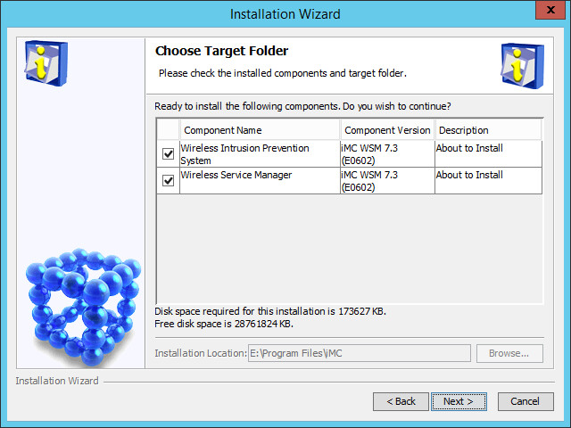
WSM installation
Install WSM in the same way other components are installed. For more information, see H3C IMC deployment guides.
As shown in Figure 1, you must install all modules except WIPS, which you can choose to install or not.
WSM licenses
WSM supports the following types of licenses:
· License of authorization—Authorizes you with the WSM component or a specific module, but does not increase the number of nodes that can be managed. For example, the locating management license only authorizes you with the locating management module.
· Node license—Increases the number of managed nodes. Node licenses can be used for authorization or expansion, or both. For example, the fit AP node license only increases the number of fit APs that can be managed, and the WIPS node license authorizes the WIPS management module and increases the number of sensors that WIPS can manage.
The basic WSM license decides whether WSM is available or not. The license does not cover all WSM modules. Modules with independent licenses include:
· WIPS Management
· Locating Management
· Network Evaluation
Table 2 WSM license and module-specific license description
|
Module |
License |
Description |
|
Wireless Service Manager |
Basic WSM license |
You must register the license to use WSM. By default, the basic WSM license includes 50 fit APs. The numbers of fat APs and ACs that can be managed are controlled by IMC platform node licenses. |
|
Fit AP node license |
This license allows you to increase the number of fit APs that can be managed. For example, for a network with 230 fit APs, you need to purchase a fit AP node license of 200 fit APs, except the 50 APs in the basic WSM license. WSM can only manage the fit APs within the license limit. If the number of fit APs on the network exceeds the maximum number permitted by the license, fit APs can be added to WSM but are not displayed. |
|
|
WTU license |
This license allows you to control the number of WTUs managed by WSM. |
|
|
Locating Management |
Basic locating management license |
This license allows you to use the X-Share locating function, Wireless Locating Based on AP function and GIS locating function. |
|
Real Time Location System (RTLS) node license |
This license allows you to use the realtime locating function and control the number of APs for realtime locating. For example, for a network with 80 APs for realtime locating, you need to purchase a license of 100 nodes. |
|
|
WIPS Management |
WIPS node license |
This license allows you to use the WIPS management module and increase the number of sensors. For example, with a WIPS node license of 50 sensors registered, you can use all WIPS functions and manage at most 50 sensors. |
|
Network Evaluation |
Network evaluation license |
This license allows you to use the network evaluation module. |
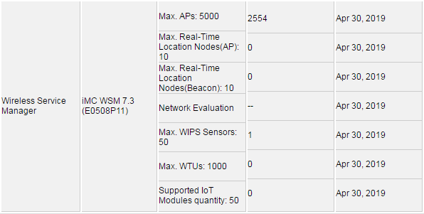
During the trial period
The trial periods for IMC are 45 days. In the trial period, every module of WSM is available, but the number of nodes is limited.
The number of supported nodes during the trial period is shown in Figure 2:
Figure 2 WSM license trial period
After the trial period
When the trial period expires, you cannot use WSM without activating the WSM basic license. If the module-specific license of a module is not activated, the module cannot be used. The module name is not displayed when you access Service > WLAN Manager from the navigation tree. Modules whose module-specific licenses are activated can still be used. For example, you cannot use the spectrum guard without activating its license, but you can still use the locating management module if its license has been activated. For information about activating a license, see H3C IMC deployment guides.
|
|
NOTE: A permanent license that has been activated cannot be removed. |
WSM home page widgets
WSM provides several wireless service home page widgets. Operators can add widgets to the IMC home page. For more information, see H3C IMC v7.3 Enterprise and Standard Platform Administrator Guide.
The following information describes each widget.
Basic functions
Each widget includes several basic functions.
Setting refresh intervals
By default, the refresh interval for each widget is 5 minutes. You can set the interval for each widget.
To set a refresh interval:
1. Click the Set
icon ![]() on the
upper right corner.
on the
upper right corner.
If the widget does not include specific functions, the Setting menu appears. If it includes specific functions, select Refresh Interval, and the Setting dialog box opens.
2. Select the refresh interval (in minutes). Options are:
¡ No Refresh
¡ 1
¡ 5
¡ 10
¡ 30
By default, the refresh interval is 5 minutes. No Refresh indicates that the widget does not automatically refresh. You can refresh it manually.
3. Click OK.
Maximum display
To maximize a widget:
1. Click the Maximize
icon ![]() on the
upper right corner.
on the
upper right corner.
2. Click the Close
icon ![]() to close the maximum display.
to close the maximum display.
Refreshing widgets
By default, the refresh interval is 5
minutes. You can refresh a widget by clicking the Refresh
icon ![]() on the upper right corner.
on the upper right corner.
Removing widgets
1. Click the Delete
icon ![]() on the
upper right corner of a widget.
on the
upper right corner of a widget.
2. Click OK in the dialog box that opens.
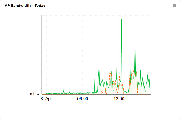
AP Bandwidth - Today
This widget shows in an area graph (Figure 3) the changes of the total transmit rate and receive rate of all APs on the wireless side, from 00:00 today to the current time. The horizontal axis represents time, and the vertical axis represents the value of the transmit rate or receive rate. The transmit rate and receive rate are represented in different colors on the graph.
Figure 3 AP Bandwidth - Today trend graph
Fit AP Model
As shown in Figure 4, the pie chart shows the number of fit APs for each fit AP model.
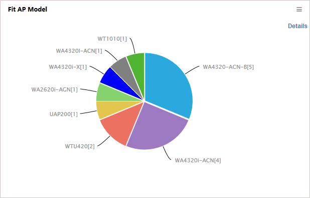
· A color represents an AP model.
· Place the cursor over a color, and a tip appears to show the AP model and the number of APs of the model.
· Click a color to enter a fit AP list. The list displays information about fit APs of the AP model.
· Click Details on the top right corner to view the number of APs for each model and the percentage to all models.
Reasons for Assoc. Failures
This widget shows in a pie chart (Figure 5) today's association failures and the reasons for the failures. The reasons are Associated client upper limit reached, Unsupported mandatory rate, Reassociation failure, Others (such as weak signal strength and blacklist), and Unknown reason.
Figure 5 Reasons for Assoc. Failures
Client Distribution
This widget shows in a pie chart (Figure 6) the number of clients by vendor, endpoint type, and OS.
Take the statistics by vendor as an example. The widget displays the number of clients for each vendor and the percentage of total clients in the pie chart on the left and lists the top 10 vendors by proportion on the right.
Click the Details link on the right. The Details window displays the number of clients and the proportion for each vendor.
Channel List
This widget lists by channel (Figure 7) the fat APs, fit APs, and clients on the network.
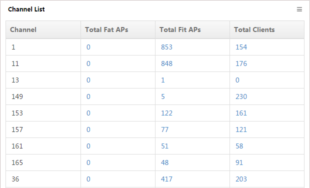
The list displays the following information:
· Channel—Number of the channel that is configured on the network.
· Total Fat APs—Number of fat APs that provide services on the channel.
· Total Fit APs—Number of fit APs that provide services on the channel.
· Total Clients—Number of clients who access the network through the channel.
To view the list of fat APs, fit APs, or clients that use the channel, click the number of a channel.
Radio Type List
This widget lists the fat APs, fit APs, and clients on the network by radio type (Figure 8).
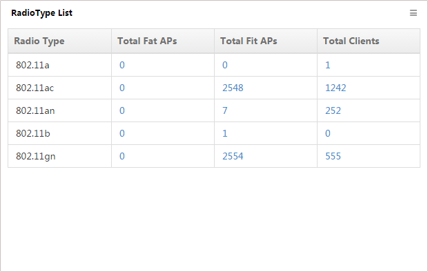
The list displays the following information:
· Radio Type—Radio type.
· Total Fat APs—Number of fat APs that provide services on this radio type.
· Total Fit APs—Number of fit APs that provide services on this radio type.
· Total Clients—Number of clients who access the network on this radio type.
To view the list of fat APs, fit APs, or clients that use the radio type, click the number for a radio type.
AC
This widget shows in a pie chart (Figure 9) the numbers of ACs by alarm level and admin status, and it lists the numbers of ACs by their reachability status below the pie chart.
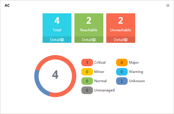
Sectors of the pie chart indicate the numbers of unknown ACs, normal ACs, and ACs that generate alarms, by alarm level. The alarm level of an AC is the same as that of the most severe alarms on the AC. To view the AC list filtered by the corresponding reachability status, click the number of Total, Reachable, or Unreachable ACs below the pie chart.
Fat AP
This widget shows in a pie chart (Figure 10) the numbers of fat APs by alarm level, and it lists the numbers of fat APs by their reachability status below the pie chart.
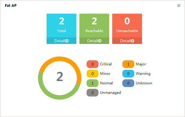
Sectors of the pie chart indicate the numbers of unknown fat APs that generate alarms, by alarm level. The alarm level of a fat AP is the same as that of the most severe alarms on the fat AP. To view the list of all fat APs, reachable fat APs, or unreachable fat APs, click the number of Total, Reachable, or Unreachable below the pie chart.
Fit AP
This widget shows in a pie chart (Figure 11) the numbers of fit APs by alarm level, and it lists the numbers of fit APs by their reachability status below the pie chart.
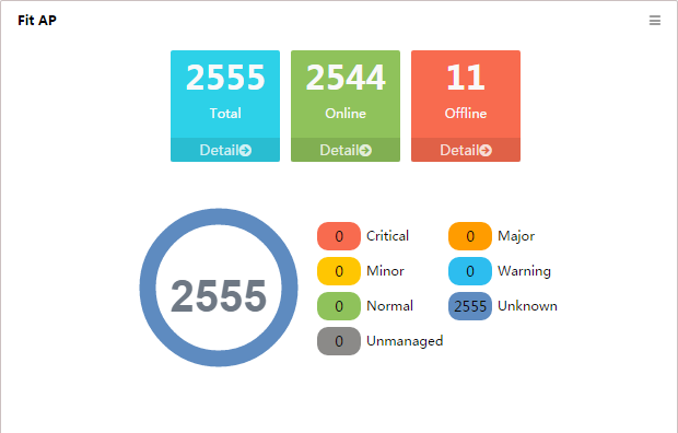
Sectors of the pie chart indicate the numbers of unknown fit APs that generate alarms, by alarm level. The alarm level of a fit AP is the same as that of the most severe alarms on the fit AP. To view the list of all fit APs, online fit APs, or offline fit APs, click the number of Total, Online, or Offline below the pie chart.
Interference Detection Count
This widget shows in a pie chart (Figure 12) the interference times of each type of device detected by Comware-based fit APs that support spectrum analysis.
Figure 12 Interference Detection Count
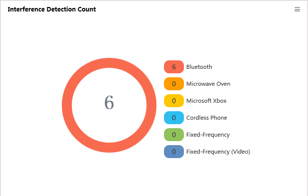
Different types of interference devices are identified by different colors. WSM can detect various types of interference devices, including the following:
· Microwave ovens
· Bluetooth devices
· Fixed-frequency transmit devices
· Fixed-frequency video transmit devices
· Cordless phones
· Microsoft Xbox
Click the number next to a device to view the device list.
Rogue AP and Rogue Client
This widget lists rogue APs and rogue clients detected by Comware-based fat APs and fit APs (Figure 13).
Figure 13 Rogue AP and Rogue Client
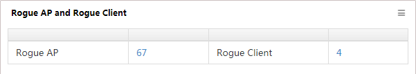
The list displays the number of rogue APs and rogue clients. Click the number to view a rogue AP or rogue client list.
SSID Rate Trend Graph
This widget shows an area graph (Figure 14) of the transmit rate and receive rate of APs with the specified SSID on the wireless side in a selected time range.
Figure 14 SSID Rate Trend Graph
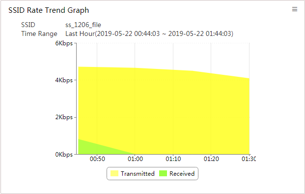
The name of the selected SSID and the time range appear at the top of the graph. The horizontal axis represents time, and the vertical axis represents the value of the transmit rate or receive rate. The transmit rate and receive rate are represented in different colors on the graph.
To set the SSID Rate Trend Graph widget:
1. On the upper right of the widget, click the Set
icon![]() , and
then select Setting.
, and
then select Setting.
The Setting window opens.
2. Select a time range from the Time Range list. Options are:
¡ Last Hour
¡ Last Day
¡ Last Week
¡ Last Month
3. Select an SSID from the SSID list.
All SSIDs in WSM are available.
4. Click OK.
SSID-Based Client Count Trend Graph
This widget shows in an area graph (Figure 15) clients who have accessed the specified SSID in a selected time range.
Figure 15 SSID-Based Client Count Trend Graph
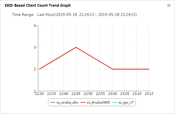
The time range appears at the top of the graph. The horizontal axis represents time, and the vertical axis represents the number of clients.
To set the SSID-Based Client Count Trend Graph widget:
1. On the upper right of the graph, click the Set
icon ![]() , and then
select Setting.
, and then
select Setting.
The Setting window opens.
2. On the Time Range list, select a time range. Options are:
¡ Last Hour
¡ Last Day
¡ Last Week
¡ Last Month
3. Click Select SSID.
The SSID List appears.
4. Select SSIDs. You can select a maximum of five.
5. Click OK.
6. View the selected SSIDs in the Setting window.
To delete SSIDs, select the target SSIDs, and then click Delete.
7. Click OK.
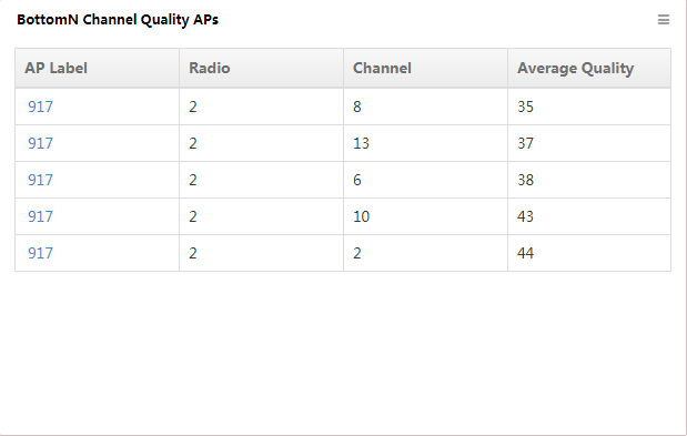
BottomN Channel Quality APs
This widget lists in descending order (Figure 16) the BottomN APs channel quality. It also lists the radio using channels, AP label, and average quality.
Figure 16 BottomN Channel Quality APs
To set the BottomN Channel Quality APs widget:
1. On the upper right of the graph, click the Set
icon ![]() , and then
select Setting.
, and then
select Setting.
The Setting window opens.
2. Select a number from the BottomN list. Options are:
¡ 5
¡ 10
¡ 20
¡ 50
¡ 100
3. Click OK.
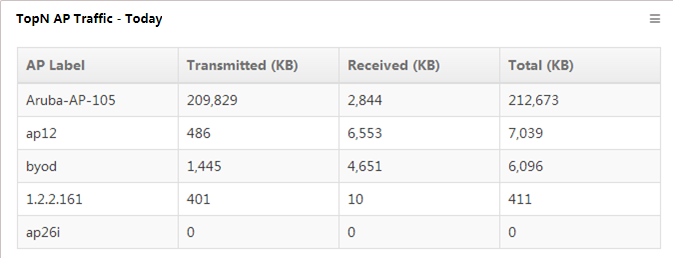
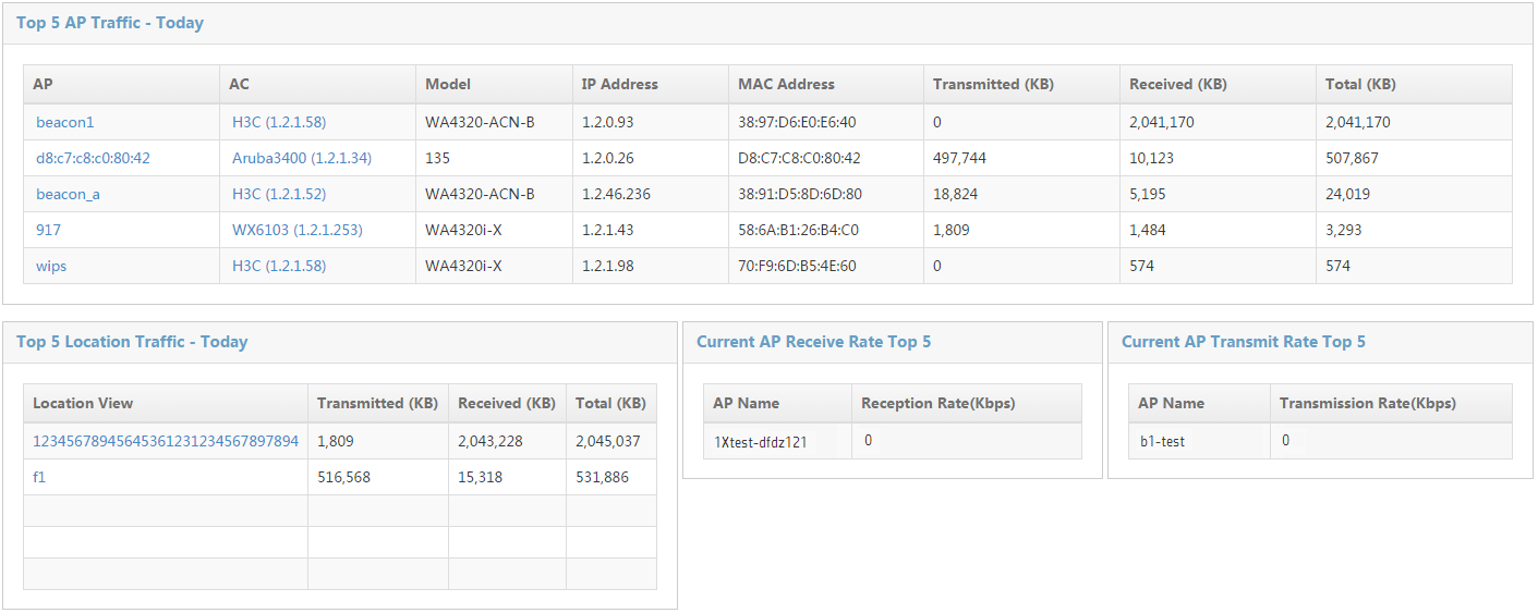
TopN AP Traffic - Today
This widget lists in descending order (Figure 17) the TopN APs with the most traffic, from 00:00 today to the current time. The list also displays the transmission traffic, receive traffic, and total traffic of each TopN AP.
Figure 17 TopN AP Traffic - Today
To set the TopN AP Traffic – Today widget:
1. On the upper right of the graph, click the Set
icon ![]() , and then
select Setting.
, and then
select Setting.
The Setting window opens.
2. Select a number from the TopN list. Options are:
¡ 5
¡ 10
¡ 20
¡ 50
¡ 100
The default value is 5.
3. Click OK.
TopN APs by Assoc. Failures
This widget lists in descending order (Figure 18) the TopN APs with the most association failures and their respective failure numbers, from 00:00 today to the current time.
Figure 18 TopN APs by Assoc. Failures

To view detailed information about the AP, click the name of an AP label.
To set the TopN APs by Assoc. Failures widget:
1. On the upper right of the graph, click the Set
icon ![]() , and then
select Setting.
, and then
select Setting.
The Setting window opens.
2. Select a number from the TopN list. Options are:
¡ 5
¡ 10
¡ 20
¡ 50
¡ 100
The default value is 5.
3. Click OK.
TopN Locations by Assoc. Failures
This widget lists in descending order (Figure 19) the TopN location views with the most association failures and their respective failure numbers, from 00:00 today to the current time.
Figure 19 TopN Locations by Assoc. Failures
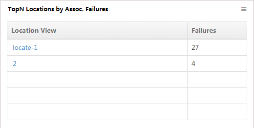
To view the sub-views and devices contained in the location view, click the name of a location view.
To set the TopN Locations by Assoc. Failures widget:
1. On the upper right of the graph, click the Set
icon ![]() , and then
select Setting.
, and then
select Setting.
The Setting window opens.
2. Select a number from the TopN list. Options are:
¡ 5
¡ 10
¡ 20
¡ 50
¡ 100
The default value is 5.
3. Click OK.
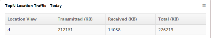
TopN Location Traffic - Today
This widget lists in descending order (Figure 20) the TopN location views with the most traffic, from 00:00 today to the current time. The list also displays the transmit traffic, receive traffic, and total traffic of each TopN location view.
Figure 20 TopN Location Traffic - Today
To set the TopN Location Traffic – Today widget:
1. On the upper right of the graph, click the Set
icon ![]() , and then
select Setting.
, and then
select Setting.
The Setting window opens.
2. Select a number from the TopN list. Options are:
¡ 5
¡ 10
¡ 20
¡ 50
¡ 100
The default value is 5.
3. Click OK.
TopN APs by Clients
This widget lists in descending order (Figure 21) the TopN APs (including fat APs and fit APs) with the most online clients and their respective client numbers, from 00:00 today to the current time.
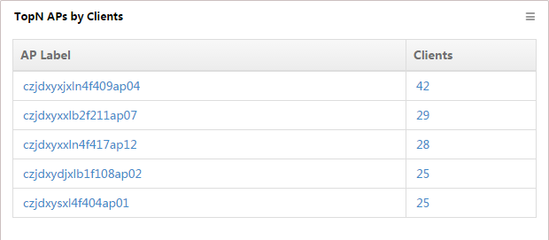
To view detailed information about the AP, click the name of an AP label. To view the list of clients who access the wireless network through the AP, click the number of clients for an AP.
To set the TopN APs by Clients widget:
1. On the upper right of the graph, click the Set
icon ![]() , and then
select Setting.
, and then
select Setting.
The Setting window opens.
2. Select a number from the TopN list. Options are:
¡ 5
¡ 10
¡ 20
¡ 50
¡ 100
The default value is 5.
3. Click OK.
TopN Locations by Clients
This widget lists in descending order (Figure 22) the TopN location views with the most online clients and their respective client numbers, from 00:00 today to the current time.
Figure 22 TopN Locations by Clients
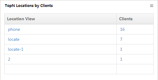
To view the sub-views and devices contained in the location view, click the name of a location view. To view the list of clients who access the wireless network through the AP in the location view, click the number of clients.
To set the TopN Locations by Clients widget:
1. On the upper right of the graph, click the Set
icon ![]() , and then
select Setting.
, and then
select Setting.
The Setting window opens.
2. Select a number from the TopN list. Options are:
¡ 5
¡ 10
¡ 20
¡ 50
¡ 100
The default value is 5.
3. Click OK.
TopN SSIDs by Clients
This widget lists in descending order (Figure 23) the TopN SSIDs with the most online clients and their respective client numbers, from 00:00 today to the current time.
Figure 23 TopN SSIDs by Clients
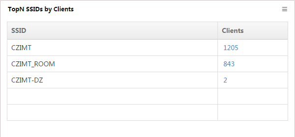
To view the list of clients who access the wireless network through the SSID, click the number of clients.
To set the TopN SSIDs by Clients widget:
1. On the upper right of the graph, click the Set
icon ![]() , and
then select Setting.
, and
then select Setting.
The Setting window opens.
2. Select a number from the TopN list. Options are:
¡ 5
¡ 10
¡ 20
¡ 50
¡ 100
The default value is 5.
3. Click OK.
Top5 ACs by Clients
This widget shows (Figure 24) the Top5 ACs with the most online clients and their respective client numbers.
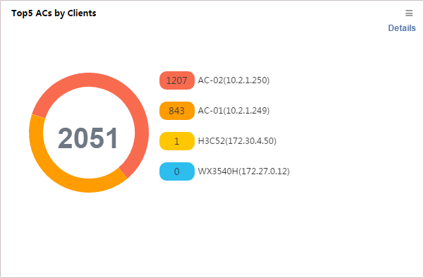
To view the number of clients associated with each AC in a list, click Details in the top right corner.
Client Count - Today
This widget shows in an area graph (Figure 25) changes in the number of online clients, from 00:00 today to the current time.
Figure 25 Client Count - Today
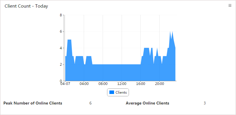
The horizontal axis represents time, and the vertical axis represents the number of online clients. The time intervals in the horizontal axis automatically adjust to the length of time.
Client Distribution
This widget shows client distribution in the specified location view by number or in a heat map (Figure 26).
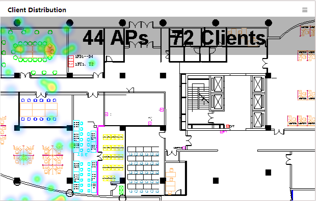
To specify a location view and the display
mode, place the cursor over the top of the widget and click the Set icon ![]() that appears. Select Setting from the menu and select a location view and the
display mode in the window that appears.
that appears. Select Setting from the menu and select a location view and the
display mode in the window that appears.
AP Threat Level Statistics
Before customizing this widget, deploy the WIPS module.
This widget shows in a pie chart (Figure 27) by AP all APs that are detected by WIPS.
Figure 27 AP Threat Level Statistics
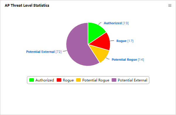
The AP type is defined by the WIPS module, including:
· Ad Hoc
· Authorized
· Rogue
· Misconfigured
· External
· Potential-Authorized
· Potential-Rogue
· Potential-External
· Uncategorized
You can click on the area of an AP type in the pie chart to view information about all APs of this type on the APs Detected page.
Click the identification of an AP type below the pie chart to hide the AP from the pie chart and click it to display it again.
Detection Information
Before customizing this widget, deploy the WIPS module.
This widget lists the number of APs, clients and SSIDs that are detected by WIPS (Figure 28).
Figure 28 Detection Information
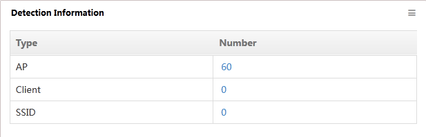
Click a number link in the Number column. For example, click the number link for an AP to view the AP detected by WIPS on the APs Detected page.
WIPS Security Event Statistics
Before customizing this widget, deploy the WIPS module.
This widget shows in a pie chart (Figure 29) by security event level the number of security events detected by WIPS.
Figure 29 WIPS Security Event Statistics
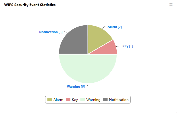
Click on an area of a security event level in the pie chart to display information about all security events of the level.
Click a security event level below the pie chart to hide security event level from the pie chart and click it to display it again.
TopN Sensors Detecting Rogues
Before customizing this widget, deploy the WIPS module.
This widget lists in descending order (Figure 30) the TopN sensors detecting rogue devices.
Figure 30 TopN Sensors Detecting Rogues
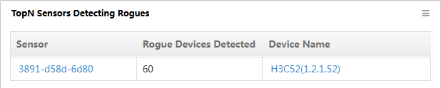
Click the label link of a sensor to view the sensor details.
Click the device link to view detailed information about the AC.
To set the TopN Sensors Detecting Rogues widget:
1. On the upper right of the graph, click the Set
icon ![]() , and then
select Setting.
, and then
select Setting.
The Setting window opens.
2. Select a number from the TopN list. Options are:
- 5
- 10
- 20
- 50
- 100
The default value is 5.
3. Click OK.
TopN Virtual Security Domains Detecting Rogues
Before customizing this widget, deploy the WIPS module.
This widget lists in descending order (Figure 31) the TopN virtual security domains detecting rogue devices.
Figure 31 TopN Virtual Security Domains Detecting Rogues
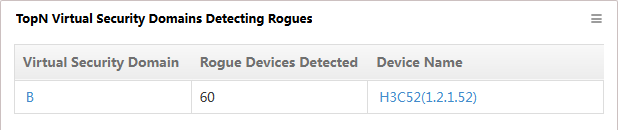
Click the domain link in the Virtual Security Domain column to view detailed information.
Click the device name link in the Device Name column to view detailed information about the domain managed by the AC.
To set the TopN Virtual Security Domains Detecting Rogues widget:
1. On the upper right of the graph, click the Set
icon ![]() , and then
select Setting.
, and then
select Setting.
The Setting window opens.
2. Select a number from the TopN list. Options are:
- 5
- 10
- 20
- 50
- 100
The default value is 5.
3. Click OK.
Wireless Alarm
This widget lists the unrecovered alarms that are generated by wireless services on the current network (Figure 32).
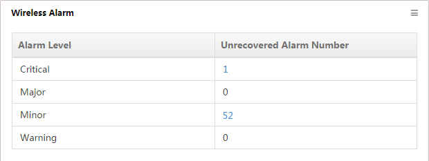
The list displays the following information:
· Alarm Level—Alarm levels are:
¡ Critical
¡ Major
¡ Minor
¡ Warning
· Alarm Number—Number of unrecovered alarms of a specific alarm level on the network.
To view all unrecovered alarms of a specific alarm level in IMC, click an alarm number.
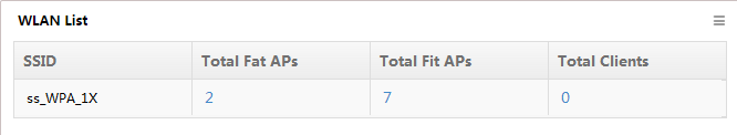
WLAN List
This widget lists by SSID (Figure 33) the distribution of fat APs, fit APs, and clients on the current network.
To set the WLAN List widget:
1. On the upper right of the graph, click the Set icon ![]() , and then select Setting.
, and then select Setting.
The Setting window opens.
2. Select from the TopN list the number of SSIDs to be displayed on the WLAN List.
3. Enter a partial or complete SSID in the SSID field to filter the SSIDs you want to display.
The WLAN List displays the SSIDs that contain the specified SSID string.
4. Click OK.
The list displays the following information:
· SSID—Name of an SSID
· Total Fat APs—Number of fat APs that have a radio bound with the SSID
· Total Fit APs—Number of fit APs that have a radio bound with the SSID
· Total Clients—Number of clients who access the network through the SSID
To view the fat APs, fit APs, or clients associated with the SSID, click a number on the list.
WLAN overview
WSM provides a WLAN overview to provide a quick understanding of status and statistics for the wireless devices and clients on the network.
The WLAN Manager contains several areas that display the different data as the wireless service home page widgets.
To access the WLAN overview page:
1. Click the Service tab on the top navigation bar.
2. From the navigation tree, select WLAN Manager > Overview.
The WLAN Overview page opens. The page displays statistics and status information about wireless devices and clients.
3. To add a widget to the Overview page, click Overview Customization at the upper right corner of the page and then add widgets.
4. To remove a widget from the Overview page,
click the Delete icon ![]() at the upper righter corner of the
widget.
at the upper righter corner of the
widget.
The following information describes the areas on the WLAN Overview page.
Shop Entry/Exit Clients
As shown in Figure 34, the bar chart shows the TopN shops with the most clients and their respective client numbers.
Figure 34 Shop Entry/Exit Clients
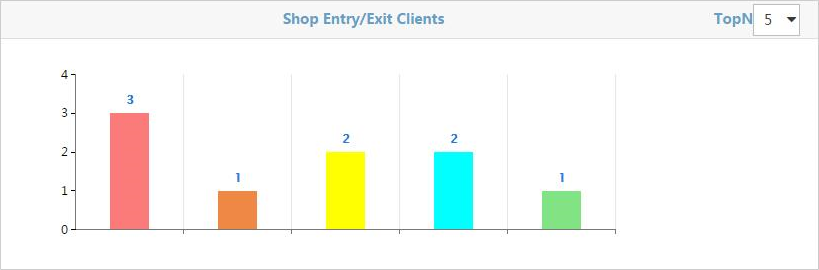
To show the shop name, place the cursor over a bar until a tip appears.
Resource Statistics
The Resource Statistics area displays AC, fit AP, and fat AP alarm statistics in histograms one by one at an interval of 5 seconds.
AC resource statistics
As shown in Figure 35, AC resource statistics show the number of ACs for each alarm level.
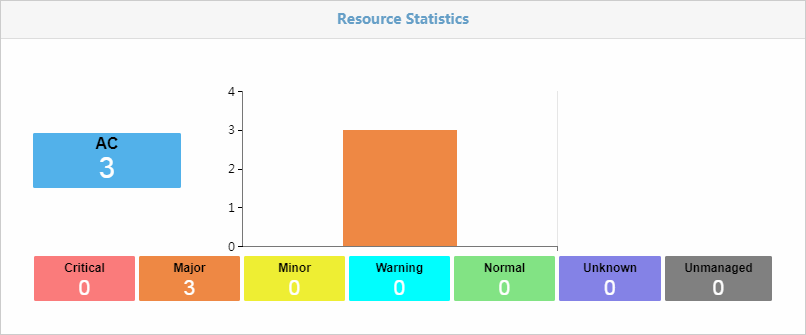
· The vertical axis shows the number of ACs in the wireless network. The colored squares below the histogram show the number of ACs for each alarm level.
· Each color reflects a different alarm level:
¡ ![]() Critical
Critical
¡ ![]() Major
Major
¡ ![]() Minor
Minor
¡ ![]() Warning
Warning
¡ ![]() Normal
Normal
¡ ![]() Unknown
Unknown
¡ ![]() Unmanaged
Unmanaged
· If you click a colored square, you can view all ACs for that alarm level.
Fit AP resource statistics
As shown in Figure 36, fit AP resource statistics show the number of fit APs for each alarm level.
Figure 36 Fit AP resource statistics
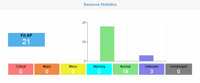
· The vertical axis shows the number of fit APs in the wireless network. The colored squares blow the histogram show the number of fit APs for each alarm level.
· Each color reflects a different alarm level:
¡ ![]() Critical
Critical
¡ ![]() Major
Major
¡ ![]() Minor
Minor
¡ ![]() Warning
Warning
¡ ![]() Normal
Normal
¡ ![]() Unknown
Unknown
¡ ![]() Unmanaged
Unmanaged
· If you click a colored square, you can view all fit APs for that alarm level.
Fat AP resource statistics
As shown in Figure 37, fat AP resource statistics show the number of fat APs for each alarm level.
Figure 37 Fat AP resource statistics
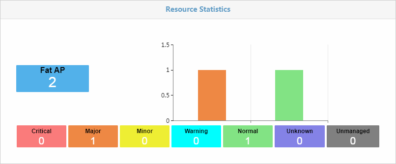
· The vertical axis shows the number of fat APs in the wireless network. The colored squares blow the histogram show the number of fat APs for each alarm level.
· Each color reflects a different alarm level:
¡ ![]() Critical
Critical
¡ ![]() Major
Major
¡ ![]() Minor
Minor
¡ ![]() Warning
Warning
¡ ![]() Normal
Normal
¡ ![]() Unknown
Unknown
¡ ![]() Unmanaged
Unmanaged
· If you click a colored square, you can view all fat APs for that alarm level.
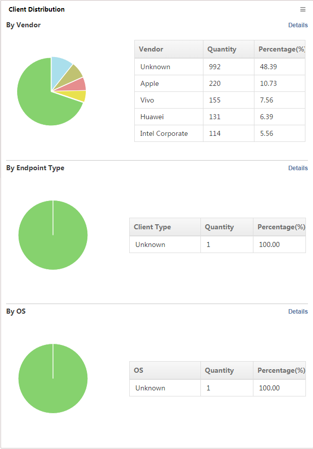
Total Clients
The Total Clients area displays total clients by type, vendor, and operating system in pie charts and forms, one-by-one, at an interval of 5 seconds.
Total clients by client type
Figure 38 Total clients by client type
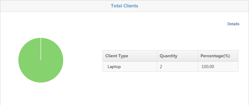
· A color represents a client type.
· The form displays the following information:
¡ Client Type—Client type.
¡ Quantity—Number of clients of the type.
¡ Percentage—Percentage of clients of the type.
· The form can display a maximum of five client types. To view information about all client types, click Details in the top right corner.
Total clients by vendor
Figure 39 Total clients by vendor
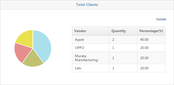
· A color represents a vendor.
· The form displays the following information:
¡ Vendor—Vendor of a client.
¡ Quantity—Number of clients of the vendor.
¡ Percentage—Percentage of clients of the vendor.
· The form can display a maximum of five vendors. To view information about all vendors, click Details in the top right corner.
Total clients by operating system
Figure 40 Total clients by operating system
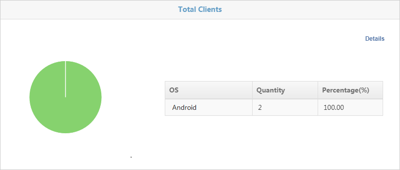
· A color represents an operating system.
· The form displays the following information:
¡ OS—Operating system of a client.
¡ Quantity—Number of clients that use the operating system.
¡ Percentage—Percentage of clients that use the operating system.
· The form can display a maximum of five operating systems. To view information about all client operating systems, click Details in the top right corner.
Client Count
The Client Count area contains the following information:
· Client count
· Client count details
· TopN clients
Viewing the client count
The trend graph in Figure 41 shows changes in the number of online clients within a specific time range.
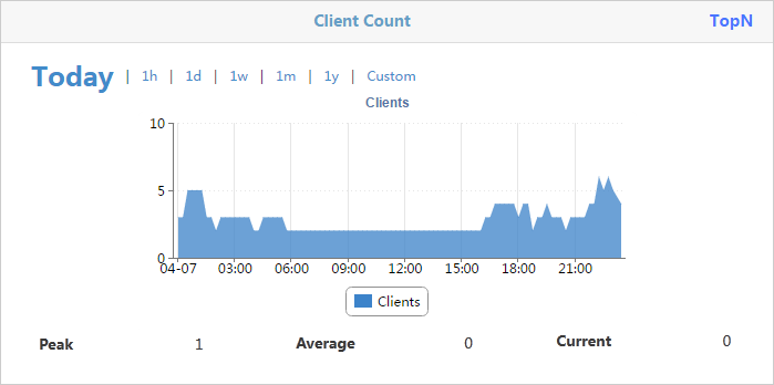
The horizontal axis represents the time range, and the vertical axis represents the number of clients. The time intervals in the horizontal axis automatically adjust to the specified time range.
You can view the changes in the number of online clients within a specific time range. Options are Today, 1h, 1d, 1w, 1m, 1y, and Custom.
If you select Custom, set the start time and the end time:
1. Click Custom.
2. In the Custom window that opens, enter a start time and end time, or select the start time/end time from the calendar that appears, in the YYYY-MM-DD hh:mm format. The end time must be later than the start time.
3. Click Query.
Changes in the number of online clients within the specified time range are displayed in the trend graph.
Viewing the client count details
1. Click Clients at the top of the Client Count trend graph.
The Details window opens. It displays the number of online clients at a specific time in a list.
2. To close the window, click the Close icon ![]() .
.
Viewing the TopN clients
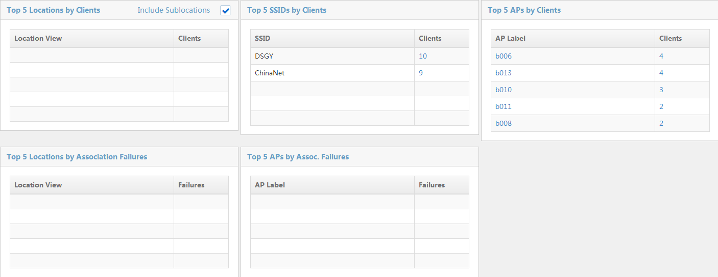
The TopN Clients page is shown in Figure 42.
The TopN Clients page contains the following lists:
· TopN Locations by Clients
The list shows the TopN location views with the most clients, in descending order. Click the name of a location view to display the sub-views and devices contained in the location view. Click the number of clients to display the list of clients in the location view.
· TopN SSIDs by Clients
The list shows the TopN SSIDs with the most clients, in descending order. Click the number of clients to display the list of clients who access the network through that SSID.
· TopN APs by Clients
The list shows the TopN APs with the most clients, in descending order. Click an AP label to see the detailed information about the AP. Click the number of clients to display the clients who access the wireless network through the AP.
· TopN Locations by Association Failures
The list shows the TopN location views with the most association failures over the previous 24 hours, in descending order. Click the name of a location view to display the sub-views and devices that are contained in the location view.
· TopN APs by Association Failures
The list shows the TopN APs with the most association failures over the previous 24 hours, in descending order. Click an AP to display the detailed information about the AP.
To view information about TopN clients:
1. Click TopN on the upper right of the Client Count trend graph.
The TopN Clients page opens.
2. Select a number from the TopN list on the upper right of the page.
Options are:
¡ 5
¡ 10
¡ 20
¡ 50
¡ 100
The default value is 20. The page refreshes to display the TopN location views, TopN SSIDs, and TopN APs with the most clients, the TopN location views with the most association failures, and the TopN APs with the most association failures.
3. To count clients in all sublocation views, select Including Sublocations on the upper right of the Top 5 Locations by Clients list.
4. Click the name of a location view on the list to display the sub-views and devices that are contained in that view.
5. Click Back to return to the WLAN Overview page.
Figure 42 TopN clients
Fit AP Model
As shown in Figure 43, the Fit AP Model area shows all AP models in the WLAN and the number of APs of each model.
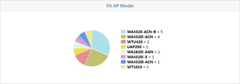
· A color represents an AP model. The number of APs of a model is shown to the right of the pie chart.
· Place the cursor over a color, and a tip appears to show the AP model and the number of APs of the model.
· Click a color to enter a fit AP list. The list displays information about fit APs of the AP model.
Located Client Trend Graph
The Located Client Trend Graph provides the trend and details of located clients.
Viewing the trend graph
The area shows the total number of associated clients and unassociated clients in an area chart, and provides the peak and average values, as shown in Figure 44.
Figure 44 Located Client Trend Graph
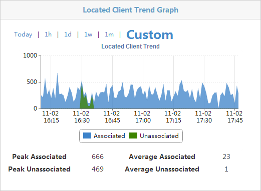
The horizontal axis indicates time and the vertical axis indicates the client count. The time intervals in the horizontal axis automatically adjust to the specified time range.
You can view the changes in the number of located clients within a specific time range. Options are Today, 1h, 1d, 1w, 1m, 1y, and Custom.
If you select Custom, set the start time and the end time:
1. Click Custom.
2. In the Custom window that opens, enter a start time and end time, or select the start time/end time from the calendar that appears, in the YYYY-MM-DD hh:mm format. The end time must be later than the start time.
3. Click Query.
Changes in the number of located clients within the specified time range are displayed in the trend graph.
Viewing located client details
On the Located Client
Trend Graph, click Located Client Trend to
view a detailed list of associated and unassociated clients for the selected
time range. Click the Close icon ![]() to close the list.
to close the list.
AP Bandwidth
The AP bandwidth contains the following information:
· AP Bandwidth
· AP Bandwidth details
· TopN traffic
Viewing the AP bandwidth
The trend graph in Figure 45 shows the changes in the transmit rate and the receive rate for the AP at the wireless side within a specific time range.
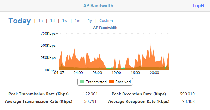
The horizontal axis represents the time range, and the vertical axis represents the number of clients. The time intervals in the horizontal axis automatically adjust to the specified time range.
You can view the changes in the transmit rate and the receive rate for the AP at the wireless side within a specific time range. Options are Today, 1h, 1d, 1w, 1m, 1y, and Custom.
If you select Custom, set the start time and the end time:
1. Click Custom.
In the Custom window that opens, enter a start time and end time, or select the start time/end time from the calendar that appears, in the YYYY-MM-DD hh:mm format. The end time must be later than the start time.
2. Click Query.
The trend graph displays changes in the transmit rate and the receive rate for the AP at the wireless side within the specified time range.
Viewing the AP bandwidth details
1. Click AP Bandwidth at the top of the trend graph.
The Details window opens. It displays the transmit rate and the receive rate of the AP at a specific time.
2. To close the window, click the Close icon ![]() .
.
Viewing the TopN traffic statistics
The TopN Traffic page is shown in Figure 46.
The TopN Traffic page contains the following lists:
· TopN AP Traffic – Today
The list shows the TopN APs with the most traffic, in descending order. The list displays the transmit traffic, the receive traffic, and total traffic statistics.
· TopN Location Traffic – Today
The list shows the TopN location views with the most traffic, in descending order. The list displays the transmit traffic, the receive traffic, and total traffic statistics.
· Current AP Receive Rate TopN
The list shows the TopN APs with the highest receiving rates and their respective receiving rates in descending order.
· Current AP Transmit Rate TopN
The list shows the TopN APs with the highest transmit rates and their respective transmit rates in descending order.
To view the TopN traffic statistics:
1. Click TopN on the upper right of the AP Bandwidth trend graph.
The TopN Traffic page opens.
2. Select a number from the TopN list on the upper right of the page.
The available options are 5, 10, 20, 50, and 100. The default value is 20. The page refreshes to display the TopN APs and location views with the most traffic.
3. Click Back to return to the WLAN Overview page.
Figure 46 TopN traffic
Wireless Alarm
The Wireless Alarm page is shown in Figure 47. The page displays alarm-level statistics for unrecovered alarms that are generated by wireless services on the current network.
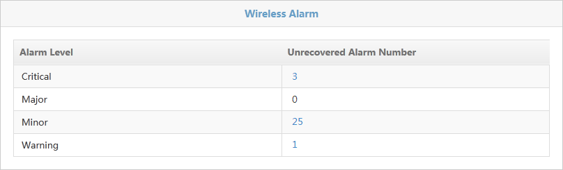
The page shows the following information:
· Alarm Level—Alarm levels are:
¡ Critical
¡ Major
¡ Minor
¡ Warning
· Alarm Number—Number of unrecovered alarms of a specific alarm level.
Click an alarm number to display all unrecovered alarms on wireless devices of a specific alarm level in IMC.
Unrecovered Wireless Alarms
The Unrecovered Wireless Alarms page is shown in Figure 48.
The page shows the following information:
· Alarm level—Alarm levels are:
¡ Critical
¡ Major
¡ Minor
¡ Warning
· Alarm description—Description for the alarm.
· Alarm time—Time when the alarm was generated.
Figure 48 Unrecovered Wireless Alarms
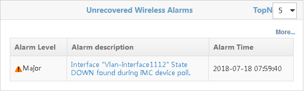
· Select a number from the TopN list on the upper right of the page. Options are 5 and 10.
· Click More… to enter the Wireless Service Alarm page as shown in "Viewing wireless service alarms."
· Click the description for an alarm to view detailed alarm information. For more information about the alarm info page, see H3C IMC v7.3 Enterprise and Standard Platform Administrator Guide.
Rogue AP and Rogue Client
The Rogue AP and Rogue Client page is shown in Figure 49.
Figure 49 Rogue AP and Rogue Client

The page displays the number of rogue APs and rogue clients.
· Click the number next to Rogue AP to view the list of rogue APs.
· Click the number next to Rogue Client to view the list of rogue clients.
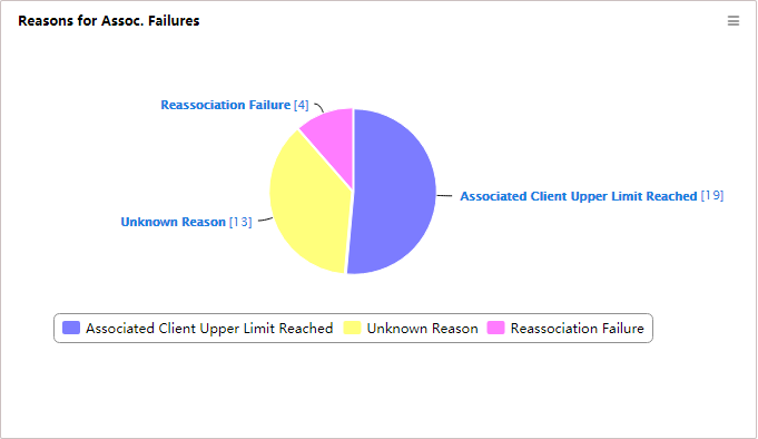
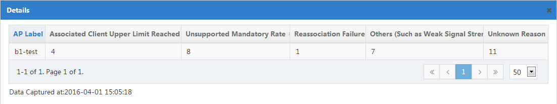
Reasons for Association Failures - Today
The Reasons for Association Failures – Today page is shown in Figure 50. The page shows in a pie chart the association failure reasons. A number represents the number of failures associated with each reason from 00:00 today to the current time. The failure reasons include:
· Associated client upper limit reached.
· Unsupported mandatory rate.
· Reassociation failure.
· Others (such as weak signal strength and blacklist).
· Unknown reason.
Figure 50 Reasons for Association Failures - Today
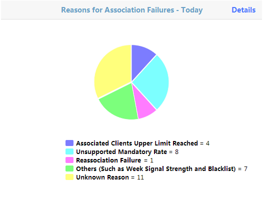
Click Details in the upper right corner of the page. The number of failures associated with each reason is shown for individual APs.
Figure 51 Details page
Channel Utilization
As shown in Figure 52, the bar chart shows TopN channel utilization in the wireless network. You can select 5 or 10 from the TopN list at the upper right corner.
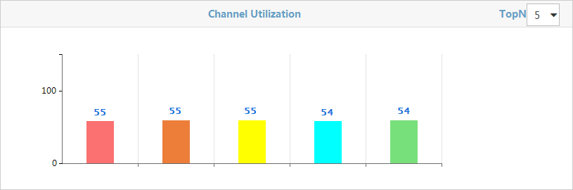
Select a number from the TopN list on the upper right of the page. Options are 5 and 10.
Clients-By Frequency
The Clients-By Frequency page shows the distribution of 5 GHz and 2.4 GHz bands and each radio type in a doughnut chart, and the number of associated clients for each radio type.
Figure 53 Clients-By Frequency
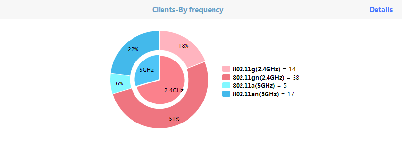
The inner ring shows the distribution of 5 GHz and 2.4 GHz bands. The outer ring shows the distribution of each radio type. The list to the right of the doughnut chart shows the number of associated clients for each radio type.
To view the number of associated clients for each radio type, click Details in the top right corner.
SSIDs by Clients
The SSIDs by Clients page is shown in Figure 54. The page lists the SSIDs that have the most associated clients, and the number of associated clients for each SSID.
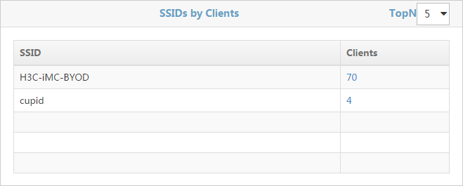
· Select a number from the TopN list on the upper right of the page. Options are 5 and 10.
· The list displays the following information:
¡ SSID—SSID name.
¡ Clients—Number of clients associated with the SSID.
· Click the number to view information about clients associated with the SSID.
Full screen monitor
Full screen monitor displays customized wireless service statistics in a dashboard. This improves user monitor experience. To view the WLAN Overview page in full screen, click Full Screen Monitor in the top right corner of the page.
Display style configuration
As shown in Figure 55, WSM provides two display styles for full screen monitor: flat style and traditional style.
Figure 55 Display style configuration
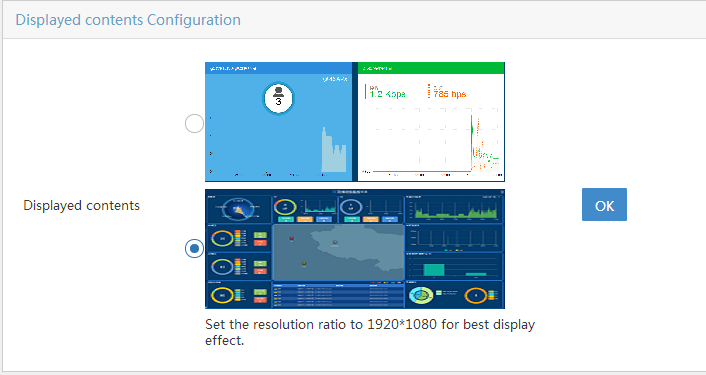
To configure the display style:
1. Click Full Screen Configuration in the top right corner.
2. Select a style of displayed contents and click OK.
3. If the second style (traditional style) is selected, configure the following settings:
¡ Title Name—Enter a name for the full screen page. The name is Wireless Device Monitoring by default.
¡ Selected Location Views—Select location views to be displayed in the scroll area of the full screen page.
¡ Location—Select a location view to be displayed in the central area of the full screen page.
¡ Include Sublocations—Select whether clients in sublocation views are included in statistics displayed in the Client Count Top 10 Location Views area.
Flat-style full screen monitor
Client Position Distribution
As shown in Figure 56, client position distribution displays the positions of clients in a wireless network. To view client information such as MAC address, username, and SSID of a client, click the icon of the client.
Click the Set
icon ![]() to select the location view topology to
be displayed.
to select the location view topology to
be displayed.
Figure 56 Client Position Distribution
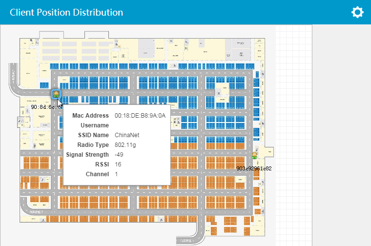
Client Vendor Distribution
As shown in Figure 57, client vendor distribution provides vendor statistics about clients in a wireless network.
Figure 57 Client Vendor Distribution
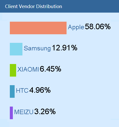
A bar chart represents the vendor name and the percentage of the clients.
Client Count Trend Graph
As shown in Figure 58, the client count trend graph provides online client statistics in a time period in a wireless network.
Figure 58 Client Count Trend Graph
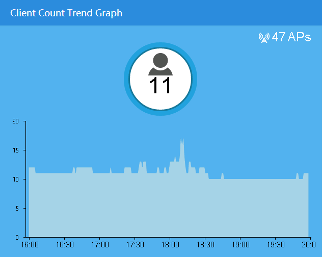
· The quantity coordinate represents the number of current online clients.
· The number on the top right of the trend graph represents the quantity of APs in the wireless network.
Wireless Bandwidth Trend Graph
As shown in Figure 59, the wireless bandwidth trend graph provides the sending and receiving rates of APs in a period.
Figure 59 Wireless Bandwidth Trend Graph
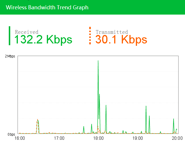
· The green number represents the total receiving bandwidth and the green line represents the receiving rate trend in a period in the wireless network.
· The red number represents the total sending bandwidth and the red line represents the sending rate trend in a period in the wireless network.
Traditional-style full screen monitor
As shown in Figure 60, traditional style full screen monitor displays AC and AP alarms and client statistics for network administrators to view the network operation status.
Figure 60 Traditional-style full screen monitor
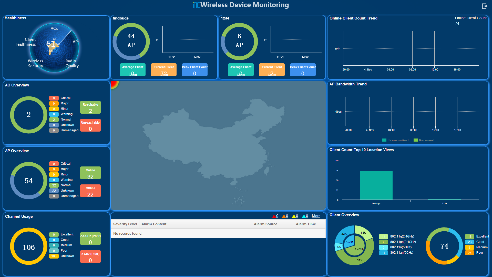
Fast WLAN deployment
WSM enables you to configure all WLAN parameters on one page to fast deploy a WLAN.
This feature supports only Comware-based and MSM ACs and fit APs.
Comware-based fast WLAN deployment
Configuring WLAN parameters
1. Click the Service tab.
2. From the navigation tree, select WLAN Manager > Fast Deploy WLAN.
3. Click the Comware Based tab.
4. On the Fast Deploy WLAN page, configure the following parameters:
Basic Information
¡ SSID—Enter a unique SSID for the service template.
¡ Enable—Select this option to enable the service template.
¡ Bind Radio—Select a radio type to which the service template is bound. Options are 2.4GHz, 5GHz, and All.
¡ Hide SSID—Select this option to hide the SSID in beacon frames sent by the fit AP. When this parameter is selected, clients cannot obtain the SSID from beacon frames and they must configure the SSID before accessing the wireless network. If this parameter is not selected, clients can obtain the SSID from the beacon frames to access the wireless network.
¡ VLAN—Specify a VLAN to which the service template is bound. Clients that access the WLAN join the VLAN automatically.
Security Information
Encryption Mode—Select an encryption mode. Options are Clear, WEP, WPA (Personal), WPA2 (Personal), WPA (Enterprise), and WPA2 (Enterprise).
¡ Clear—No data frames are encrypted.
¡ WEP—WEP encryption is used. Configure the following parameters:
- Cipher Suite—Select a cipher suite. Options are WEP40, WEP104, and WEP128, with security strength in ascending order.
- Key—Enter a key. The key length varies by the cipher suite. The key length is 5, 13, and 16 alphanumeric characters for WEP40, WEP104, and WEP128 keys, respectively.
- Confirm Key—Enter the key again.
- Key Index—Enter a key index. WEP supports 1 to 4 key indexes.
¡ WPA (Personal) or WPA2 (Personal)—PSK authentication is used. Configure the following parameters:
- PSK—Enter a pre-shared key in the range of 8 to 63 characters.
- Confirm PSK—Enter the PSK again.
¡ WPA (Enterprise) or WPA2 (Enterprise)—802.1X authentication is used. Configure the following parameter:
- Domain—Select a domain. To configure a domain, click Domain. For more information, see "Configuring a domain."
Extension Information
¡ Max Clients—Enter the maximum online clients permitted in the WLAN.
¡ Layer 2 Isolation—Select this option to enable Layer 2 isolation. This parameter must be configured in combination with the user-isolation vlan command executed on the AC. If the function is enabled, clients in the permitted MAC address list can communicate with other clients in the same VLAN.
5. In the AP List field, click Add.
6. In the dialog box that opens, specify one or more of the following query criteria to query an AP.
¡ Device Label—Enter the device label of the AP. WSM supports fuzzy matching for this field.
¡ Location View—Select the location view of the AP.
¡ Serial Number—Enter the serial number of the fit AP. WSM supports fuzzy matching for this field.
¡ Model—Select the AP model. Options are Unlimited and all AP models available for the WSM.
¡ IP Address—Enter a partial or complete IPv4 address of the fit AP. WSM supports fuzzy matching for this field.
¡ Online Status—Select the online status for the fit AP. Options are: Unlimited, Online, and Offline.
¡ AC—Select the AC that manages the fit AP. Options are Unlimited and all ACs in WSM.
An empty field or a field that is set to Unlimited does not serve as a query criterion.
7. Click Query.
The list displays all APs matching the query criteria.
Click Reset to clear the query criteria and display all APs that are not bound to another service template.
8. Select the APs you want to add, and click OK.
All selected APs are displayed in the AP list.
9. Click OK.
Configuring a RADIUS policy
The following information describes RADIUS policy configuration.
Adding a RADIUS policy
1. Click the Service tab.
2. From the navigation tree, select WLAN Manager > Fast Deploy WLAN.
3. In the Security Information field, click Domain.
4. On the Domain Configuration page, click RADIUS Policy.
5. On the RADIUS Policy page, click Add.
6. On the Add RADIUS Policy page, configure the following parameters:
¡ RADIUS Policy—Enter the RADIUS policy name.
¡ Server Type—Select the server type. Options are Extended and Standard.
¡ Primary Authentication—Enter the IP address of the primary authentication server.
¡ Secondary Authentication—Enter the IP address of the backup authentication server.
¡ Primary Accounting—Enter the address of the primary accounting server.
¡ Secondary Accounting—Enter the address of the backup accounting server.
¡ Authentication Key—Enter the key for authentication.
¡ Confirm Authentication Key—Enter the key for authentication again.
¡ Accounting Key—Enter the key for accounting.
¡ Confirm Accounting Key—Enter the key for accounting again.
7. Click OK.
Modifying a RADIUS policy
1. Click the Service tab.
2. From the navigation tree, select WLAN Manager > Fast Deploy WLAN.
3. In the Security Information field, click Domain.
4. On the Domain Configuration page, click RADIUS Policy.
5. On the RADIUS Policy
page, click the Modify icon ![]() for a RADIUS
policy.
for a RADIUS
policy.
6. On the page that opens, modify RADIUS policy parameters as needed. See "Adding a RADIUS policy."
7. Click OK.
Deleting a RADIUS policy
1. Click the Service tab.
2. From the navigation tree, select WLAN Manager > Fast Deploy WLAN.
3. In the Security Information field, click Domain.
4. On the Domain Configuration page, click RADIUS Policy.
5. On the RADIUS Policy
page, click the Delete icon ![]() for a RADIUS
policy.
for a RADIUS
policy.
A confirmation dialog box opens.
6. Click OK.
Configuring a domain
The following information describes domain configuration.
Adding a domain
1. Click the Service tab.
2. From the navigation tree, select WLAN Manager > Fast Deploy WLAN.
3. In the Security Information field, click Domain.
4. On the Domain Configuration page, click Add.
5. On the Add Domain page, configure the following parameters:
¡ Domain Name—Enter the domain name.
¡ RADIUS Policy—Select a RADIUS policy. For more information, see "Configuring a RADIUS policy."
6. Click OK.
Modifying a domain
1. Click the Service tab.
2. From the navigation tree, select WLAN Manager > Fast Deploy WLAN.
3. In the Security Information field, click Domain.
4. On the Domain
Configuration page, click the Modify icon ![]() for a domain.
for a domain.
5. On the page that opens, modify domain parameters as needed. See "Adding a domain."
6. Click OK.
Deleting a domain
1. Click the Service tab.
2. From the navigation tree, select WLAN Manager > Fast Deploy WLAN.
3. In the Security Information field, click Domain.
4. On the Domain
Configuration page, click the Delete icon ![]() for a domain.
for a domain.
A confirmation dialog box opens.
5. Click OK.
MSM fast WLAN deployment
1. Click the Service tab.
2. From the navigation tree, select WLAN Manager > Fast Deploy WLAN.
3. Click the MSM tab.
4. On the Fast Deploy WLAN page, configure the following parameters:
Basic Information
¡ VSC Name—Enter a VSC name.
¡ SSID—Enter a unique SSID for the service template, a string of 1 to 32 characters. The string can include digits, letters, spaces, and the following special characters:
- Dollar sign ($)
- Percent sign (%)
- Parentheses (())
- Asterisk (*)
- Plus sign (+)
- Comma (,)
- Hyphen (-)
- Dot (.)
- Colon (:)
- Semicolon (;)
- Equal sign (=)
- Question mark (?)
- At sign (@)
- Square brackets ([ ])
- Caret (^)
- Apostrophe (')
- Braces ({ })
- Vertical bar (|)
- Tilde (~)
¡ Status—Select a WLAN state. Options are Enable and Disable. A WLAN can provide wireless services only when it is in Enable state.
¡ VLAN Tagging—Options are Enable and Disable. Select Enable to bind a VLAN to the WLAN, or Disable to not bind a VLAN to the WLAN.
¡ VLAN ID—Enter the ID of a VLAN to be bound to the WLAN. This field is configurable only when VLAN Tagging is set to Enable.
¡ Tagged Port—Select a VLAN type. Options are LAN_Port and Internet_Port. This field is configurable only when VLAN Tagging is set to Enable.
¡ Broadcast SSID—Enable APs to broadcast the SSID or disable APs from broadcasting the SSID. Options are Enable and Disable. If you select Enable, clients can discover the WLAN by scanning. If you select Disable, clients cannot discover the WLAN by scanning and you must configure the SSID on clients for them to access the WLAN.
¡ Inner-Client Blocking—Enable clients accessing the WLAN to communicate with each other or disable clients accessing the WLAN from communicating with each other. Options are Enable and Disable.
Security Information
¡ Encryption Mode—Select an encryption mode. Options are None, Static WEP, Dynamic WEP, WPA Pre-Shared Key, and WPA Dynamic. Parameters for different encryption modes are shown in Table 3.
Authentication
¡ Authentication Mode—Select an authentication mode. Options are None, HTML Authentication, MAC Authentication, and 802.1X Authentication. Parameters for different authentication modes are shown in Table 6.
Filter
¡ Wireless MAC Filter—Select this option to enable MAC address filtering.
- MAC Address List—Select a MAC address list.
- Filter Action—Select a filtering action. Options are Allow and Block. If you select Allow, only clients whose MAC addresses are in the MAC address list are allowed to access the WLAN. If you select Block, clients whose MAC addresses are in the MAC address list are forbidden to access the WLAN.
¡ Wireless IP Filter—Select this option to enable IP address filtering.
- IP Address—Enter an IP address.
- Mask—Enter a subnet mask for the IP address.
Click Add to add the network segment to the IP address list. Clients whose IP addresses are within network segments in the IP address list are allowed to access the WLAN. To delete a network segment, select it from the list and click Delete.
Binding information
¡ Group Name—Select a group to be bound to the WLAN. The list displays groups configured on the AC.
¡ Egress Network—Select a VLAN to be bound to the AC. The list displays VLANs configured on the AC.
¡ Dual-Radio Behavior—Select radios to be bound to the fit AP. Options are Both Radios, Radio 1 Only, and Radio 2 Only.
Selected Devices
¡ All ACs—Send WLAN configuration to all ACs.
¡ Selected ACs—Send WLAN configuration to the specified ACs.
5. Click OK.
Managing MSM series access controllers
An MSM series device requires firmware 5.5 or a higher version. WSM cannot manage devices that use lower versions.
WSM enables administrators to create and manage AC + fit AP networks through MSM series ACs. IMC WSM automatically manages all ACs that are added to the IMC platform. Figure 61 shows the AC + fit AP network.

Before you create a new AC + fit AP network in WSM, complete the following tasks:
· Configure the AC so that it can access the network.
· Connect fit APs to the AC, and make sure the fit APs and the AC can reach each other.
· Configure SNMP communities and specify the IP address of the WSM server as the management console for the AC, and add the AC to the IMC platform.
To create an AC + fit AP network in WSM:
1. (Optional.) Add fit AP groups, and assign the fit APs managed by the AC to these groups. For more information about configuring fit AP groups, see "Configuring fit AP groups."
2. Configure WLANs on the AC, and bind the WLANs to the fit AP groups so that fit APs in a group can provide wireless service for clients. For more information about configuring WLANs, see "Configuring WLANs."
3. (Optional.) Configure the same parameters for multiple radios in batches on the AC to reduce repetitive operations and improve efficiency. For more information, see "Configuring radios in batches."
To manage an existing wireless network, you only need to manage the ACs in WSM without creating an AC + fit AP network in WSM.
Viewing the AC list
The AC List page displays information about all managed ACs in IMC.
To view the AC list:
1. Click the Service tab.
2. From the navigation tree, select WLAN Manager > Resource Management > ACs.
The AC List page displays all ACs.
AC List
¡ Status—Current alarm status of the AC.
¡ Device Label—Device label of the AC. Click the device label of an AC to view its details.
A device label that carries an icon ![]() indicates the AC
is a team AC, and the AC details page displays the team information and the
team members.
indicates the AC
is a team AC, and the AC details page displays the team information and the
team members.
A device label that carries an icon ![]() indicates that
the management console of the AC is not the WSM server host, and that some of
the management functions in IMC are not available for the AC. Operators can log
in to the Web Manager of the AC, specify the WSM server host (by IP address) as
the AC's management console, and then synchronize the AC to IMC. After that,
the icon
indicates that
the management console of the AC is not the WSM server host, and that some of
the management functions in IMC are not available for the AC. Operators can log
in to the Web Manager of the AC, specify the WSM server host (by IP address) as
the AC's management console, and then synchronize the AC to IMC. After that,
the icon ![]() disappears.
disappears.
|
|
NOTE: A team AC contains multiple ACs that work together to provide wireless services. You cannot configure team ACs in WSM. To do so, log in to the web manager of a specific AC. |
¡ Model—Model of the AC.
¡ IP Address—IP address of the AC when it was added to IMC. For a team AC, this field displays the virtual IP address of the team AC.
¡ Total APs—Total number of fit APs managed by the AC. Click the number to view all of the managed fit APs.
¡ Online APs—Number of online fit APs managed by the AC. Click the number to view all of the managed online fit APs.
¡ Online Clients—Number of clients that are associated with the fit APs managed by the AC. Click the number to view all of the online clients.
¡ Last Sync Time—Time when the AC configuration was last synchronized.
¡ Sync Result—Last synchronization result. Options are Succeeded, Synchronizing, and Failed.
¡ Operation—Click the Operation icon ![]() for the AC to display the operation menu.
for the AC to display the operation menu.
The operational tasks provided in the Operation menu are as follows:
- Group Configuration
- WLAN configuration
- RADIUS Policy
- Radio Batch Configuration
- Global AP Parameter Config
- Configure AC Global Country/Region Code
- Threshold Configuration
- View Topology
- Ping
- TraceRoute
- Open Web Manager
- Telnet
- SSH
|
|
NOTE: · The Operation menu for an MSM series AC is different from that of other vendors' ACs. · The Threshold Configuration option appears only when Clients Associated with AC (Minor) or Clients Associated with AC (Major) is enabled. For more information, see "Setting alarm thresholds." |
If the AC List contains enough entries, the following navigational aids are displayed:
· Click the Next Page
icon ![]() to page
forward in the AC List.
to page
forward in the AC List.
· Click the Last Page
icon ![]() to page
forward to the end of the AC List.
to page
forward to the end of the AC List.
· Click the Previous Page
icon ![]() to page
backward in the AC List.
to page
backward in the AC List.
· Click the First Page
icon ![]() to page
backward to the front of the AC List.
to page
backward to the front of the AC List.
Click 8, 15, 50, 100, or 200 at the upper right of the AC List to specify the number of items you want to display on each page.
You can sort the AC List by every field except the Operation field. Click the column label to sort the list by the selected field. The column label allows you to toggle between the sort options specific to each field.
Synchronizing ACs
WSM supports synchronizing AC configuration automatically or manually. By default, IMC automatically synchronizes ACs every 2 hours (see HPEH3C IMC v7.3 Enterprise and Standard Platform Administrator Guide). You can also manually synchronize ACs as needed.
To manually synchronize ACs:
1. Click the Service tab.
2. From the navigation tree, select WLAN Manager > Resource Management > ACs.
The AC List page displays all ACs.
3. Select the ACs you want to synchronize.
4. Click Synchronize to start synchronizing the selected ACs.
The page is refreshed to display the most recent AC information after you complete the process.
Querying ACs
WSM provides basic query and advanced query. Basic query criteria include several key parameters for quick searches. Advanced query offers various query criteria for precise matching.
To query ACs:
1. Click the Service tab.
2. From the navigation tree, select WLAN Manager > Resource Management > ACs.
The AC List page displays all ACs.
3. Perform a basic query:
a. Enter the device label (case-insensitive) or IP address of the AC.
WSM supports fuzzy matching for this field. For example, if you enter 19, all ACs with device labels or IP addresses containing 19 are queried.
b. Click the Query icon
![]() .
.
The Device List displays all ACs that match the query criteria.
c. Clear the Query
field, and then click the Query icon ![]() to display all
ACs.
to display all
ACs.
4. Perform an advanced query:
a. Click ![]() next
to the Query field to expand the Query area. Click it again to hide the Query area.
next
to the Query field to expand the Query area. Click it again to hide the Query area.
b. Specify one or more of the following query criteria:
¡ Device Label—Enter the device label of the AC. WSM supports fuzzy matching for this field.
¡ IP Address—Enter a partial or complete IPv4 address of the AC. WSM supports fuzzy matching for this field.
¡ Device Status—Select a device state for the AC. Options are:
- Unlimited
- Critical
- Major
- Minor
- Warning
- Normal
- Unmanaged
- Unknown
¡ Connectivity Status—Select a connectivity state for the AC. Options are Unlimited, Reachable, and Unreachable.
¡ Vendor—Select the vendor of the AC. Options are Unlimited, H3C, HP, Cisco, and Aruba.
An empty field or a field that is set to Unlimited does not serve as a query criterion.
c. Click Query.
The AC List displays all ACs matching the query criteria.
d. Click Reset to clear the query criteria and display all ACs.
Viewing brief information about an AC
1. Click the Service tab.
2. From the navigation tree, select WLAN Manager > Resource Management > ACs.
The AC List page displays all ACs.
3. Click the device label of an AC.
The page displays brief information about the AC.
Device Information
¡ Device Label—Device label of the AC.
¡ Device Status—Alarm status of the AC.
¡ IP Address—IPv4 address of the AC.
¡ Device Model—Device model of the AC.
The Wireless Service Information area provides AP information, client information, and team information for the AC. For more information, see "Viewing detailed information about an AC."
The Client Count graph and the AP Bandwidth graph provide online client and AP bandwidth trends. For more information, see "Client Count" and "AP Bandwidth."
The Wireless Service Alarm area provides information about the alarms that the AC generates. For more information, see "Viewing wireless service alarms."
Viewing detailed information about an AC
1. Click the Service tab.
2. From the navigation tree, select WLAN Manager > Resource Management > ACs.
The AC List page displays all ACs.
3. Click the device label of an AC.
4. In the top right corner of the brief AC information page, click More Detailed.
The AC details page opens.
This information only describes the wireless service information about the AC. For other information displayed on the AC details page, see H3C IMC v7.3 Enterprise and Standard Platform Administrator Guide.
5. Click the Wireless Service Information tab.
All of the wireless service information for the AC appears on this tab.
AP Information
¡ Online Fit APs—Number of online fit APs managed by the AC. Click the number to view all of the managed online fit APs.
¡ Offline Fit APs—Number of offline fit APs managed by the AC. Click the number to view all of the managed offline fit APs.
Client Information
¡ Online Clients—Number of clients that are associated with the fit APs managed by the AC. Click the number to view the list of online clients.
Team Information
This area appears only when the selected AC is a team AC.
A team AC is a group of ACs that work together as a single virtual AC to provide wireless services for clients. You cannot configure team ACs in WSM, and must log in to the web manager of an AC to do so. For more information about team ACs, see the device configuration guide.
¡ Team Name—Name of the team.
¡ Online Duration of Master—Online time of the master AC.
¡ Status—State of the member AC. Options are:
- Discovery/Up
- Up
- Down
- Discovery/Down
- Outside
- Unknown
¡ Role—Role played by the member AC in the team. Options are:
- Slave
- Master
- Preferred Master
- Unknown
¡ IP Address—Actual IP address of the member AC.
¡ SN—Serial number of the member AC.
¡ MAC Address—MAC address of the member AC.
¡ Online Duration—Online duration of the member AC.
Configuring fit AP groups
WSM allows you to manage fit APs by group. Before configuring fit AP groups, make sure the management console of the AC is set as the IP address of the WSM server.
A fit AP is added automatically to the system-defined group Default Group when it first connects to an AC. You can move a fit AP from the one group to another group.
For fit APs in a group to provide wireless service for clients, you must bind the group to WLANs. For information about configuring WLANs, see "Configuring WLANs."
You can access the group configuration feature from the AC List page, the AC details page, or the configuration management page. This information uses the AC List page as an example.
Viewing the fit AP groups on an AC
1. Click the Service tab.
2. From the navigation tree, select WLAN Manager > Resource Management > ACs.
The AC List page displays all ACs.
3. Click the Operation
icon ![]() for an AC.
for an AC.
4. From the menu, select Group Configuration.
The Group List displays all fit AP groups on the AC.
Group List
¡ Name—Name of the group. Click the name of a group to display the Fit AP List page of the group.
¡ APs in Group—Number of fit APs in the group.
¡ Bind to WLAN—Click the Bind to WLAN icon ![]() to display the bound WLAN list page of the group.
to display the bound WLAN list page of the group.
¡ Group Parameter Config—Click the Group Parameter Config icon ![]() for a group to enter the page for configuring the group parameters.
For more information, see "Configuring group parameters."
for a group to enter the page for configuring the group parameters.
For more information, see "Configuring group parameters."
¡ Configure AP Monitor Status—Click the
Configure AP Monitor Status ![]() icon to enter the
page for configuring AP monitor status for the group. For more information, see
"Configuring AP monitor
status for a group."
icon to enter the
page for configuring AP monitor status for the group. For more information, see
"Configuring AP monitor
status for a group."
¡ Modify—Click the Modify icon ![]() to enter the page for modifying the group.
to enter the page for modifying the group.
¡ Delete—Click the Delete icon ![]() to delete the group.
to delete the group.
|
|
NOTE: You cannot modify or delete the Default Group on an AC. |
If the Group List contains enough entries, the following navigational aids are displayed:
· Click the Next Page
icon ![]() to page
forward in the Group List.
to page
forward in the Group List.
· Click the Last Page
icon ![]() to page
forward to the end of the Group List.
to page
forward to the end of the Group List.
· Click the Previous Page
icon ![]() to page
backward in the Group List.
to page
backward in the Group List.
· Click the First Page
icon ![]() to page
backward to the front of the Group List.
to page
backward to the front of the Group List.
Click 8, 15, 50, 100, or 200 at the upper right of the Group List to specify the number of items you want to display on each page.
You can sort the Group List by the Group field and APs in Group field. Click the column label to sort the list by the selected field. The column label allows you to toggle between the sort options specific to each field.
Synchronizing groups
This function allows you to synchronize information about all APs in the specified groups in batches.
To synchronize groups:
1. Click the Service tab.
2. From the navigation tree, select WLAN Manager > Resource Management > ACs. The AC List page displays all ACs.
3. Click the Operation
icon ![]() for the
target AC.
for the
target AC.
4. Select Group Configuration from the menu.
The Group List displays all fit AP groups on the AC.
5. Select one or more groups.
6. Click Synchronize to start synchronizing AP information in the selected groups.
Adding a group
1. Click the Service tab.
2. From the navigation tree, select WLAN Manager > Resource Management > ACs.
The AC List page displays all ACs.
3. Click the Operation
icon ![]() for an AC.
for an AC.
4. From the menu, select Group Configuration.
The Group List displays all fit AP groups on the AC.
5. Click Add.
The Add Group window opens.
6. Enter a name for the fit AP group in the Name field.
The name must be unique in WSM.
7. Click OK.
Modifying a group
You can modify the name and country or region code for all fit AP groups except the Default Group.
To modify a fit AP group:
1. Click the Service tab.
2. From the navigation tree, select WLAN Manager > Resource Management > ACs.
The AC List page displays all ACs.
3. Click the Operation
icon ![]() for an AC.
for an AC.
4. From the menu, select Group Configuration.
The Group List displays all fit AP groups on the AC.
5. Click the Modify icon ![]() for a group.
for a group.
The Modify Group window opens.
6. Modify the group name in the Name field.
7. Click the box next to the Inherited field to enable fit APs in the group to inherit the country or region code of the AC to which the group belongs.
Or clear the box and then manually configure a country code for the group in the Country/Region Code field.
8. Select the country or region code for the group from the Country/Region Code list. This parameter is valid only when the Inherited option is not selected.
9. Click OK.
Batch binding and unbinding WLANs with a group
This function allows you to view all of the WLANs bound to a fit AP group, bind WLANs in batches, or remove WLAN bindings in batches.
To bind or unbind WLANs with a fit AP group in batches:
1. Click the Service tab.
2. From the navigation tree, select WLAN Manager > Resource Management > ACs.
The AC List page displays all ACs.
3. Click the Operation
icon ![]() for an AC.
for an AC.
4. From the menu, select Group Configuration.
The Group List displays all fit AP groups on the AC.
5. Click the Bind to WLAN icon
![]() for the
target group.
for the
target group.
The Bound WLAN List displays all WLANs on
the AC. A checked box ![]() indicates the WLAN is already bound to a group.
indicates the WLAN is already bound to a group.
6. Bind or unbind the WLANs:
¡ To
bind the WLANs, select ![]() the WLANs you want
to bind to the group, and then configure the parameters in one of the following
ways:
the WLANs you want
to bind to the group, and then configure the parameters in one of the following
ways:
- Egress Network—Select the VLAN bound to the AC. Options include all VLAN IDs configured on the AC.
- Dual-Radio Behavior—Select the radios bound to the fit APs. Options are Both Radios, Radio 1 Only, and Radio 2 Only.
¡ To unbind the WLANs, deselect the WLANs you want to unbind from the group.
7. Click OK.
Configuring group parameters
WSM enables you to configure radio parameters in a group by AP model. After you configure this feature, the radios of a fit AP will inherit parameters of the group to which the fit AP belongs.
To configure parameters for a group on an AC:
1. Click the Service tab.
2. From the navigation tree, select WLAN Manager > Resource Management > ACs.
The AC List page displays all ACs.
3. Click the Operation
icon ![]() for an AC.
for an AC.
4. From the menu, select Group Configuration.
The Group List displays all fit AP groups on the AC.
5. Click the Group
Parameter Config icon ![]() for a group.
for a group.
The AP Model List displays all the AP models supported on the AC.
6. Click the AP model for which you want to configure radio parameters.
7. Click the box next to the Inherited field located on the top right corner of the page to inherit the AP global parameters of the AC, and then go to step 8.
Or
Clear the Inherited box and manually configure the radio parameters for the fit AP model.
Radio parameters vary with the operating mode:
For a radio with an operating mode of Monitor, the Max Transmission Power, Admin Status, Scan Ratio, and Bands to scan parameters do not appear.
For a radio with an operating mode of Sensor, only the Description field appears.
For a radio with an operating mode of Access point and Local mesh or Local mesh only, the Neighborhood scanning parameters do not appear.
¡ Radio Type—Select a radio type. Available options depend on the country code and the AP model.
¡ Max Transmission Power—Enter the maximum transmit power of the antenna. The value range varies by device model. For more information, see the device manual.
¡ Admin Status—Select an administrative state for the radio. Options are Up and Down.
¡ Channels in Use—Select the working channel of the radio. The value range depends on the radio type. If you select Auto, a fit AP selects an idle channel as the working channel.
¡ Operating Mode—Select the operating mode as follows:
- Access Point and Local Mesh—Standard operating mode provides support for all wireless functions.
- Access Point Only—Only provides access point functionality. Local mesh links cannot be created.
- Local Mesh Only—Only provides local mesh functionality. Wireless client stations cannot connect.
- Monitor—Disables access point and local mesh functions.
- Sensor—Only monitors the wireless signals in the surrounding environment. Use this option for continuous scanning across all channels in all supported wireless modes.
¡ Description—Enter a description for the radio.
For HP MSM410/MSM430/MSM460/MSM466/MSM466-R APs, WSM enables you to configure the Neighborhood scanning parameters.
¡ Scan Ratio(%)—Enter the percentage of time spent on scanning channels other than the operating channel. This parameter appears only when the Operating Mode of the radio is Access point only.
¡ Dwell Time(ms)—Enter the amount of time (in milliseconds) that a radio remains on a channel while performing channel scanning.
¡ Scan Mode—Select a scan mode for the radio. Options are Passive and Active.
- Passive—The AP listens to the channel to detect wireless traffic, but does not transmit any probes.
- Active—The AP uses probe request frames to speed up neighbor detection.
¡ Bands to Scan—Select the bands to scan. Options are Both Bands and Operating band only.
- Both Bands—The AP scans both the 2.4GHz and 5GHz bands.
- Operating band only—The AP scans the operating band only.
¡ Channels to Scan—Select the channels to scan. Options are All channels, Regulatory channels only, and Non-excluded channels only.
- All channels—The AP scans all the channels in the band where the radio is operating.
- Regulatory channels only—The AP scans only the channels supported by the country code of the radio.
- Non-excluded channels only—The AP will not scan any channels in the automatic channel exclusion list.
8. Click OK.
Configuring AP monitor status for a group
WSM enables you to configure AP monitor status for a group. The AP monitor status for a group can be inherited by fit APs in the group.
1. Click the Service tab.
2. From the navigation tree, select WLAN Manager > Resource Management > ACs.
The AC List page displays all ACs.
3. Click the Operation
icon ![]() for an AC.
for an AC.
4. From the menu, select Group Configuration.
The Group List displays all fit AP groups on the AC.
5. Click the Configure AP
Monitor Status icon ![]() .
.
The Configure AP Monitor Status page opens.
6. Modify the AP monitor parameters for the group:
¡ Group Name—Group name, which cannot be modified.
¡ Inherited—Click the box to enable the group to inherit the AP monitor status from the AC. Or clear the box and then manually configure the AP Monitor Status for the group.
¡ AP Monitor Status—Select an AP monitor status for the group. Options are Enable and Disable. This parameter is valid only when the Inherited box is not selected.
7. Click OK.
Deleting a group
Deleting a fit AP group deletes all of the information related to the group. The fit APs in the group are automatically assigned to the default group. You cannot delete the Default Group on an AC.
To delete a group:
1. Click the Service tab.
2. From the navigation tree, select WLAN Manager > Resource Management > ACs.
The AC List page displays all ACs.
3. Click the Operation
icon ![]() for an AC.
for an AC.
4. From the menu, select Group Configuration.
The Group List displays all fit AP groups on the AC.
5. Click the Delete icon ![]() for a group.
for a group.
A confirmation dialog box opens.
6. Click OK.
Viewing the fit APs in a group
1. Click the Service tab.
2. From the navigation tree, select WLAN Manager > Resource Management > ACs.
The AC List page displays all ACs.
3. Click the Operation
icon ![]() for an AC.
for an AC.
4. From the menu, select Group Configuration.
The Group List displays all fit AP groups on the AC.
5. Click the name of a fit AP group.
The Fit AP List displays all fit APs in the group.
Querying fit APs in a group
1. Click the Service tab.
2. From the navigation tree, select WLAN Manager > Resource Management > ACs.
The AC List page displays all ACs.
3. Click the Operation
icon ![]() for an AC.
for an AC.
4. From the menu, select Group Configuration.
The Group List displays all fit AP groups on the AC.
5. Click the name of a group.
The Fit AP List displays all fit APs in the group.
6. Specify one or more of the following query criteria in the query area:
¡ AP Label—Enter the label of the fit AP. WSM supports fuzzy matching for this field
¡ AP Name—Enter the name of the fit AP. WSM supports fuzzy matching for this field.
¡ Serial Number—Enter the serial number of the fit AP. WSM supports fuzzy matching for this field.
¡ IP Address—Enter the IPv4 address of the fit AP. WSM supports fuzzy matching for this field.
¡ Online Status—Select an online state of the fit AP. Options are Online and Offline.
7. Click Query.
The Fit AP List displays all fit APs in the group that match the query criteria. Click Reset to clear the query criteria and display all fit APs in the group.
Adding fit APs to a group
One fit AP can belong to only one group. After you add a fit AP to a group, it is removed from its original group.
To add fit APs to a group:
1. Click the Service tab.
2. From the navigation tree, select WLAN Manager > Resource Management > ACs.
The AC List page displays all ACs.
3. Click the Operation
icon ![]() for an AC.
for an AC.
4. From the menu, select Group Configuration.
The Group List displays all fit AP groups on the AC.
5. Click the name of a group.
The Fit AP List displays all fit APs in the group.
6. Click Add to Group.
The Select Device window opens, displaying all the fit APs managed by the AC where the group is configured.
7. Specify one or more of the following query criteria to search for the fit APs you want to add to the group.
¡ Label—Enter the label of the Fit AP. WSM supports fuzzy matching for this field.
¡ Serial Number—Enter the serial number of the fit AP. WSM supports fuzzy matching for this field.
¡ IP Address—Enter the IPv4 address of the fit AP. WSM supports fuzzy matching for this field.
¡ Online Status—Select the online status of the fit AP. Options are Online and Offline.
¡ Group Name—Select the current group to which the fit AP belongs. Options include all existing groups in WSM.
¡ Location View—Specify the name of the location view to which the fit AP belongs. WSM supports fuzzy matching for this field
8. Click Query.
The Fit AP List displays all fit APs matching the query criteria.
9. Select the fit APs you want to add to the group.
10. Click OK.
The selected fit APs appear in the Fit AP List of the group.
Deleting fit APs from a group
Deleting a fit AP from a group does not delete it from the system. The deleted fit AP is moved automatically to the Default Group on the AC. You cannot delete fit APs from the Default Group.
To delete fit APs from a group:
1. Click the Service tab.
2. From the navigation tree, select WLAN Manager > Resource Management > ACs.
The AC List page displays all ACs.
3. Click the Operation
icon ![]() for an AC.
for an AC.
4. From the menu, select Group Configuration.
The Group List displays all fit AP groups on the AC.
5. Click the name of a group.
The Fit AP List displays all fit APs in the group.
6. Select the fit APs you want to remove from the group.
7. Click Delete from this Group.
A confirmation dialog box opens.
8. Click OK.
Moving fit APs from one group to another group
1. Click the Service tab.
2. From the navigation tree, select WLAN Manager > Resource Management > ACs.
The AC List page displays all ACs.
3. Click the Operation
icon ![]() for an AC.
for an AC.
4. From the menu, select Group Configuration.
The Group List displays all fit AP groups on the AC.
5. Click the name of the group where the fit APs to be moved are located.
The Fit AP List displays all fit APs in the group.
6. Select the fit APs you want to move.
7. Click Change Group.
The Change Group dialog box opens.
8. Select the group to which you want to move the selected fit APs from the Group list.
9. Click OK.
Configuring WLANs
This function allows you to configure the VSC on an AC. A VSC is the wireless service that can be provided by fit APs managed by an AC. After being bound to a fit AP group, a WLAN deploys the VSC to all of the fit APs in the group, so that the fit APs can provide wireless services for clients.
You can access the WLAN configuration feature from the AC List page, the AC details page, or the configuration management page. The following information uses the AC List page as an example.
Viewing WLANs on an AC
1. Click the Service tab.
2. From the navigation tree, select WLAN Manager > Resource Management > ACs.
The AC List page displays all ACs.
3. Click the Operation
icon ![]() for an AC.
for an AC.
4. From the menu, select WLAN Configuration.
The WLAN List displays all WLANs on the AC.
WLAN List
¡ SSID—SSID of the WLAN. Click the SSID of a WLAN to view its details.
¡ VSC Name—Name of the VSC.
¡ Enable Status—State of the WLAN, Enable or Disable. A WLAN can be used by radios only when it is in Enable state.
¡ Broadcast SSID—Select whether to enable fit APs in groups bound with the WLAN to broadcast the SSID in beacon frames.
¡ Encryption Mode—Encryption mode used by the WLAN. Options are:
- None
- Static WEP
- Dynamic WEP
- WPA Pre-Shared Key
- WPA Dynamic
¡ Authentication Mode—Authentication mode used by the WLAN. Options are:
- None
- HTML Authentication
- 802.1X Authentication
- MAC Authentication
To configure this parameter, you must log in to the web manager of the AC.
¡ VLAN ID—VLAN ID bound to the WLAN. Clients that access the WLAN are added automatically to the bound VLAN.
¡ Operation—Click the Operation icon ![]() for the WLAN to display the operation menu.
for the WLAN to display the operation menu.
From the ![]() Operation menu, you can modify and delete the specified WLAN, and bind the
WLAN to fit AP groups.
Operation menu, you can modify and delete the specified WLAN, and bind the
WLAN to fit AP groups.
If the WLAN List contains enough entries, the following navigational aids are displayed:
· Click the Next Page
icon ![]() to page
forward in the WLAN List.
to page
forward in the WLAN List.
· Click the Last Page
icon![]() to page
forward to the end of the WLAN List.
to page
forward to the end of the WLAN List.
· Click the Previous Page
icon ![]() to page
backward in the WLAN List.
to page
backward in the WLAN List.
· Click the First Page
icon ![]() to page
backward to the front of the WLAN List.
to page
backward to the front of the WLAN List.
Click 8, 15, 50, 100, or 200 at the upper right of the WLAN List to specify the number of items you want to display on each page.
You can sort the WLAN List by every field except the Operation field. Click the column label to sort the list by the selected field. The column label allows you to toggle between the sort options specific to each field.
Viewing the WLAN details
1. Click the Service tab.
2. From the navigation tree, select WLAN Manager > Resource Management > ACs.
The AC List page displays all ACs.
3. Click the Operation
icon ![]() for an AC.
for an AC.
4. From the menu, select WLAN Configuration.
5. Click the SSID of the WLAN you want to view.
The WLAN Details page opens.
WLAN details
Basic Information
¡ VSC Name—Name of the VSC.
¡ Status—State of the WLAN, Enable or Disable. A WLAN can provide wireless services only when it is in Enable state.
¡ SSID—SSID of the WLAN.
¡ VLAN Tagging—Indicates whether the WLAN can be bound to a VLAN.
¡ VLAN ID—ID of the VLAN bound to the WLAN. Wireless clients that access the WLAN are added automatically to the bound VLAN. This field is empty if the VLAN Tagging is set to Disable.
¡ Tagged port—Select a VLAN type. Options are LAN_Port and Internet_Port. This field is configurable only when VLAN Tagging is set to Enable.
¡ Broadcast SSID—Indicates whether to enable fit APs in groups bound with the WLAN to broadcast the SSID in beacon frames.
¡ Inter-Client Blocking—Enable or disable access between clients that access the WLAN.
Security Information
¡ Encryption—Encryption mode used by the WLAN. Options are:
- None
- Static WEP
- Dynamic WEP
- WPA Pre-Shared Key
- WPA Dynamic
¡ Key Length—Length of the key. Options are 64 bits and 128 bits.
¡ Key Type—Type of the key. Options are ASCII and HEX.
¡ Key Index—Index of the key. Options are 1, 2, 3, and 4.
¡ Key—key value.
¡ Version—WPA version. Options are WPA, WPA2, and WPA + WPA2.
¡ Cipher—Link layer protocol used for data frame encryption and decryption. Options are TKIP, CCMP (AES), and TKIP+CCMP (AES).
- TKIP—Temporal key integrity protocol uses the RC4 algorithm as WEP does, but provides more secure protection for WLAN.
- CCMP (AES)—Counter mode with CBC-MAC protocol is a Counter-Mode/CBS-MAC mechanism based on AES to provide high security.
¡ Pre-Shared Key—Pre-shared key.
Primary Authentication Server
¡ Address—IP address or domain name of the primary authentication server.
¡ Port—Authentication port of the primary authentication server.
¡ Secret—Password used for communication between the AC and the primary authentication server.
¡ Retry Interval(s)—Time the AC must wait before retrying to connect to the primary authentication server after a connection times out.
¡ Retry Timeout(s)—Whether response timeout timer is enabled and if yes, the specified response timeout time.
Secondary RADIUS Server
¡ Secondary RADIUS Server—Whether to enable the secondary authentication server.
¡ Address—IP address or domain name of the secondary authentication server.
¡ Secret—Password used for communication between the AC and the secondary authentication server.
Adding a WLAN
1. Click the Service tab.
2. From the navigation tree, select WLAN Manager > Resource Management > ACs.
The AC List page displays all ACs.
3. Click the Operation
icon ![]() for an AC.
for an AC.
4. From the menu, select WLAN Configuration.
The WLAN List displays all WLANs on the AC.
5. Click Add.
6. Configure the following parameters for the WLAN:
¡ VSC Name—Enter the name of the VSC.
¡ Status—Select a WLAN state. Options are Enable and Disable. A WLAN can provide wireless services only when it is in Enable state.
¡ SSID—Enter the unique SSID of the WLAN, a string of 1 to 32 characters. The string can include digits, letters, spaces, and the following special characters:
- Ampersand sign (&)
- Angle brackets (< >)
- Apostrophe (')
- Asterisk (*)
- At sign (@)
- Braces ({ })
- Caret (^)
- Colon (:)
- Comma (,)
- Dollar sign ($)
- Dot (.)
- Double quotation marks (")
- Equal sign (=)
- Exclamation point (!)
- Forward slash (/)
- Hyphen (-)
- Parentheses (())
- Percent sign (%)
- Plus sign (+)
- Pound sign (#)
- Semicolon (;)
- Square brackets ([ ])
- Tilde (~)
- Underscore (_)
- Vertical bar (|)
¡ VLAN Tagging—Select whether to enable the WLAN to be bound to a VLAN. Options are Enable and Disable.
¡ VLAN ID—Select the VLAN ID bound to the WLAN. Valid value range is 1 to 4094. All wireless clients that access the WLAN are added automatically to the bound VLAN. This field is configurable only when VLAN Tagging is set to Enable.
¡ Tagged port—Select a VLAN type. Options are LAN_Port and Internet_Port. This field is configurable only when VLAN Tagging is set to Enable.
¡ Broadcast SSID—Select whether to enable fit APs to broadcast the SSID in beacon frames. If you select Enable, fit APs in the group bound with the WLAN periodically advertises their presences by broadcasting their SSIDs in beacon frames. If you select Disable, the fit APs do not broadcast their SSIDs, and a client must configure the SSID manually before accessing the wireless network.
¡ Inter-Client Blocking—Enable or disable access between clients that access the WLAN.
7. Configure the following security parameters:
¡ Encryption—Select an encryption mode for the WLAN. Options are:
- None
- Static WEP
- Dynamic WEP
- WPA Pre-Shared Key
- WPA Dynamic
For each encryption mode, you need to specify different parameters. For more information, see Table 3.
8. Configure the following authentication parameters as needed:
¡ Authentication Mode—Select an authentication mode for the WLAN. Options are:
- None
- HTML Authentication
- MAC Authentication
- 802.1X Authentication
For each authentication mode, you need to specify different parameters. For more information, see Table 6.
9. Configure the following filter parameters as needed:
¡ Wireless MAC Filter—Enable MAC address filtering.
- MAC Address List—Select a MAC address list.
- Filter Action—Select a filtering action. Options are Allow and Block. If you select Allow, only clients whose MAC addresses are in the MAC address list are allowed to access the WLAN. If you select Block, clients whose MAC addresses are in the MAC address list are forbidden to access the WLAN.
¡ Wireless IP Filter—Enable IP address filtering.
- IP Address—Enter an IP address.
- Mask—Enter a subnet mask for the IP address.
Click Add to add the network segment to the IP address list. Clients whose IP addresses are within network segments in the IP address list are allowed to access the WLAN. You can select a network segment from the list and click Delete to delete it.
10. Select fit AP groups to be bound to the WLAN from the group list.
11. Click OK.
Table 3 shows the security information parameters.
Table 3 Security information parameters
|
Encryption |
Security information parameters |
|
None |
No security parameters need to be configured. |
|
Static WEP |
· Key Length—Select the key length. Options are 64 bits and 128 bits. · Key Type—Select the key type. Options are ASCII and HEX. · Key Index—Select the key index. Options are 1, 2, 3, and 4. · Key—Enter the value of the key. Valid value range is determined by Key Length and Key Type. For more information, see Table 4. |
|
Dynamic WEP |
No security parameters need to be configured. |
|
WPA Pre-Shared Key |
· Version—Select a WPA version. Options are WPA, WPA2, and WPA or WPA2. The default cipher value varies with the WPA version. For more information, see Table 5. · Cipher—Select a link layer encryption protocol. Options are TKIP, CCMP (AES), and TKIP+CCMP (AES). The parameter is determined by Encryption and Version. · Key Type—Key type defaults to ASCII, which cannot be modified. · Pre-Shared Key—Enter the pre-shared key. |
|
WPA Dynamic |
· Version—Select a WPA version. Options are WPA, WPA2, and WPA or WPA2. The default cipher value varies with WPA versions. For more information, see Table 5. · Cipher—Select a link layer encryption protocol. Options are TKIP, CCMP (AES), and TKIP+CCMP (AES). The parameter is determined by Encryption and Version. |
Table 4 shows the key value range.
|
Key type |
64 bits |
128 bits |
|
ASCII |
A string of 5 alphanumeric characters |
A string of 13 alphanumeric characters |
|
HEX |
A 10-digit hexadecimal number |
A 26-digit hexadecimal number |
Table 5 shows the cipher default value.
|
Version |
Default cipher value (cannot be modified) |
|
WPA |
TKIP |
|
WPA2 |
CCMP (AES) |
|
WPA or WPA2 |
TKIP + CCMP (AES) |
Table 6 shows the authentication parameters.
Table 6 Authentication parameters
|
Authentication mode |
Authentication parameter |
|
None |
No authentication parameters are needed. |
|
HTML Authentication |
· Local—Enable local authentication. · Remote—Enable remote authentication. ¡ Active—Authenticate clients through an Active Directory server. ¡ RADIUS—Authenticate clients through a RADIUS server, and select a RADIUS policy in the RADIUS field. ¡ Authentication timeout—Enter a timeout time in seconds. If the RADIUS server does not respond within the timeout time, the authentication fails. |
|
802.1X Authentication |
· Local—Enable local authentication. · Remote—Enable remote authentication. ¡ Active—Authenticate clients through an Active Directory server. ¡ RADIUS—Authenticate clients through a RADIUS server, and select a RADIUS policy in the RADIUS field. |
|
MAC Authentication |
· Local—Enable local authentication. · Remote—Enable remote authentication. · RADIUS—Authenticate clients through a RADIUS server, and select a RADIUS policy in the RADIUS field. |
Modifying a WLAN
1. Click the Service tab.
2. From the navigation tree, select WLAN Manager > Resource Management > ACs.
The AC List page displays all ACs.
3. Click the Operation
icon ![]() for an AC.
for an AC.
4. From the menu, select WLAN Configuration.
The WLAN List displays all WLANs on the AC.
5. Click the Operation icon ![]() for a WLAN.
for a WLAN.
6. Select Modify.
The page for modifying the WLAN opens.
7. Modify the following parameters for the WLAN:
¡ VSC Name—Enter the name of the VSC.
¡ Status—Select a WLAN state. Options are Enable and Disable. A WLAN can provide wireless services only when it is in Enable state.
¡ SSID—Enter the unique SSID of the WLAN, a string of 1 to 32 characters. For valid characters in the SSID string, see "Adding a WLAN."
¡ VLAN Tagging—Select whether to enable the WLAN to be bound to a VLAN. Options are Enable and Disable.
¡ VLAN ID—Select the VLAN ID bound to the WLAN. Valid value range is 1 to 4094. All wireless clients that access the WLAN are added automatically to the bound VLAN. This field is configurable only when VLAN Tagging is set to Enable.
¡ Tagged port—Select a VLAN type. Options are LAN_Port and Internet_Port. This field is configurable only when VLAN Tagging is set to Enable.
¡ Broadcast SSID—Select whether to enable fit APs to broadcast the SSID in beacon frames. If you select Enable, fit APs in the group bound with the WLAN periodically advertise their presences by broadcasting their SSIDs in beacon frames. If you select Disable, the fit APs do not broadcast their SSIDs, and a client must manually configure the SSID before accessing the wireless network.
¡ Inter-Client Blocking—Select Enable or Disable to enable or disable the inter-client blocking feature. The inter-client blocking feature disables clients that access the WLAN from accessing each other.
8. Modify the following security parameters:
¡ Encryption—Select an encryption mode for the WLAN. Options are:
- None
- Static WEP
- Dynamic WEP
- WPA Pre-Shared Key
- WPA Dynamic
You need to specify different parameters for each encryption mode. For more information, see Table 3.
9. Modify the following authentication parameters as needed:
¡ Authentication mode—Select an authentication mode for the WLAN. Options are:
- None
- HTML Authentication
- MAC Authentication
- 802.1X Authentication
You need to specify different parameters for each authentication mode. For more information, see Table 6.
10. Modify the following filter parameters as needed:
¡ Wireless MAC Filter—Enable MAC address filtering.
- MAC Address List—Select a MAC address list.
- Filter Action—Select a filtering action. Options are Allow and Block. If you select Allow, only clients whose MAC addresses are in the MAC address list are allowed to access the WLAN. If you select Block, clients whose MAC addresses are in the MAC address list are forbidden to access the WLAN.
¡ Wireless IP Filter—Enable IP address filtering.
- IP Address—Enter an IP address.
- Mask—Enter a subnet mask for the IP address.
Click Add to add the network segment to the IP address list. Clients whose IP addresses are within network segments in the IP address list are allowed to access the WLAN. You can select a network segment from the list and click Delete to delete it.
11. Select fit AP groups to be bound to the WLAN in the group list.
12. Click OK.
Batch binding/unbinding groups with a WLAN
This function allows you to view all of the groups bound to a WLAN, bind groups in batches, or remove group bindings in batches.
You can access the Group Bindings function from the AC List page, the AC details page, or the configuration management page. The following information uses the AC List page as an example.
To bind/unbind groups with a WLAN in batches:
1. Click the Service tab.
2. From the navigation tree, select WLAN Manager > Resource Management > ACs.
The AC List page displays all ACs.
3. Click the Operation icon ![]() for an AC.
for an AC.
4. From the menu, select WLAN Configuration.
The WLAN List displays all WLANs on the AC.
5. Click the Operation icon ![]() for a WLAN.
for a WLAN.
6. From the menu, select Group Bindings.
The Bound Group List displays all groups
on the AC. A checkbox ![]() indicates the group is already bound to the WLAN.
indicates the group is already bound to the WLAN.
7. Click the boxes ![]() for the groups
you want to bind to the WLAN, and configure the following parameters in one of
the following ways:
for the groups
you want to bind to the WLAN, and configure the following parameters in one of
the following ways:
¡ Egress Network—Select the VLAN bound to the AC. Options include all VLAN IDs configured on the AC.
¡ Dual-Radio Behavior—Select the radios bound to the fit APs. Options are Both Radios, Radio 1 Only, and Radio 2 Only.
Or
Clear the boxes ![]() for
the groups you want to unbind from the WLAN.
for
the groups you want to unbind from the WLAN.
8. Click OK.
Deleting a WLAN
You cannot delete a WLAN that has been bound to fit AP groups. After you delete a WLAN, all information related to the WLAN is deleted, and all of the clients that are accessing the WLAN are logged out.
To delete a WLAN:
1. Click the Service tab.
2. From the navigation tree, select WLAN Manager > Resource Management > ACs.
The AC List page displays all ACs.
3. Click the Operation
icon ![]() for an AC.
for an AC.
4. From the menu, select WLAN Configuration.
The WLAN List displays all WLANs on the AC.
5. Click the Operation icon ![]() for a WLAN.
for a WLAN.
6. From the menu, select Delete.
A confirmation dialog box opens.
7. Click OK.
Configuring RADIUS policies
A RADIUS policy is a collection of parameters for the RADIUS server connected to the AC. The RADIUS server uses these parameters to provide remote authentication.
You can access the RADIUS policy configuration feature from the AC List page, the AC details page, or the WLAN configuration page. The following information uses the AC List page as an example.
Viewing the RADIUS policy list
1. Click the Service tab.
2. From the navigation tree, select WLAN Manager > Resource Management > ACs.
The AC List page displays all ACs.
3. Click the Operation
icon ![]() for an AC.
for an AC.
4. From the menu, select RADIUS Policy.
The RADIUS Policy List displays all RADIUS policies on the AC.
RADIUS Policy List
¡ RADIUS Policy—RADIUS policy name.
¡ Authentication Port—Port used by the RADIUS authentication server to listen for authentication packets.
¡ Primary Authentication—IP address of the primary authentication server.
¡ Secondary Authentication—IP address of the secondary authentication server.
¡ Modify—Click the Modify icon ![]() to modify the RADIUS policy. For more information, see "Modifying a RADIUS policy"
to modify the RADIUS policy. For more information, see "Modifying a RADIUS policy"
¡ Delete—Click the Delete icon ![]() to delete the RADIUS policy. For more information, see "Deleting a RADIUS policy"
to delete the RADIUS policy. For more information, see "Deleting a RADIUS policy"
If the RADIUS Policy List contains enough entries, the following navigational aids are displayed:
· Click the Next Page
icon ![]() to page
forward in the RADIUS Policy List.
to page
forward in the RADIUS Policy List.
· Click the Last Page
icon![]() to page
forward to the end of the RADIUS Policy List.
to page
forward to the end of the RADIUS Policy List.
· Click the Previous Page
icon ![]() to page
backward in the RADIUS Policy List.
to page
backward in the RADIUS Policy List.
· Click the First Page
icon ![]() to page
backward to the front of the RADIUS Policy List.
to page
backward to the front of the RADIUS Policy List.
Click 8, 15, 50, 100, or 200 at the upper right of the RADIUS Policy List to specify the number of items you want to display on each page.
You can sort the RADIUS Policy List by every field except the Modify and Delete fields. Click the column label to sort the list by the selected field. The column label allows you to toggle between the various sort options specific to each field.
Adding a RADIUS policy
1. Click the Service tab.
2. From the navigation tree, select WLAN Manager > Resource Management > ACs.
The AC List page displays all ACs.
3. Click the Operation
icon ![]() for an AC.
for an AC.
4. From the menu, select RADIUS Policy.
The RADIUS Policy List displays all RADIUS policies on the AC.
5. Click Add to enter the Add RADIUS Policy page.
6. Configure the primary authentication server.
¡ Profile Name—Enter the RADIUS policy name.
¡ Address—Enter the IP address of the primary authentication server.
¡ Authentication Port—Enter the port used by the authentication server to listen for authentication packets. The port is 1812 by default.
¡ Secret—Enter the shared key used for communications between the AC and the authentication server.
¡ Confirm Shared Key—Enter the shared key again.
¡ Retry Interval(s)—Enter the time the AC must wait before retrying to connect to the authentication server after a connection times out. The interval is 10 seconds by default.
¡ Retry Timeout(s)—Enable the server response timeout timer, and specify the server response timeout. The timeout is 60 seconds by default. If an AC sends an authentication request to the authentication server, but receives no response in the specified time, it determines that the authentication request timed out. If you do not enable this feature, the AC determines whether an authentication request has timed out according to the default timeout value configured on the RADIUS server.
7. (Optional.) Configure the secondary authentication server.
Select Secondary RADIUS Server to enable the secondary RADIUS server.
¡ Address—Enter the IP address of the secondary authentication server.
¡ Secret—Enter the shared key used for communications between the AC and the secondary authentication server.
¡ Confirm Shared Key—Enter the shared key again.
8. Click OK.
Modifying a RADIUS policy
1. Click the Service tab.
2. From the navigation tree, select WLAN Manager > Resource Management > ACs.
The AC List page displays all ACs.
3. Click the Operation
icon ![]() for an AC.
for an AC.
4. From the menu, select RADIUS Policy.
The RADIUS Policy List displays all RADIUS policies on the AC.
5. Click the Modify icon ![]() for a RADIUS policy.
for a RADIUS policy.
6. On the page that opens, modify RADIUS policy parameters as needed. See "Adding a RADIUS policy."
7. Click OK.
Deleting a RADIUS policy
1. Click the Service tab.
2. From the navigation tree, select WLAN Manager > Resource Management > ACs.
The AC List page displays all ACs.
3. Click the Operation
icon ![]() for an AC.
for an AC.
4. From the menu, select RADIUS Policy.
The RADIUS Policy List displays all RADIUS policies on the AC.
5. Click the Delete icon ![]() for a RADIUS policy.
for a RADIUS policy.
A confirmation dialog box opens.
6. Click OK.
Configuring radios in batches
To ease radio parameter configuration and reduce repetitive operations, WSM allows you to configure public parameters for multiple radios of the fit APs managed by an AC in batches. Parameters include the following:
· Radio type
· Maximum transmit power
· Admin status
· Channel in use
· Operating mode
· Description
· Neighborhood scanning
You can access the Radio Batch Configuration function from the AC List page, the AC details page, or the configuration management page. The following information uses the AC List page as an example.
To configure radios in batches:
1. Click the Service tab.
2. From the navigation tree, select WLAN Manager > Resource Management > ACs.
The AC List page displays all ACs.
3. Click the Operation icon ![]() for an AC.
for an AC.
4. From the menu, select Radio Batch Configuration.
The page for configuring radios in batches opens.
5. Select and set the parameters:
¡ Radio Type—Select a radio type from the list. Options are:
- 802.11a
- 802.11b
- 802.11g
- 802.11bg
- 802.11at
- 802.11an
- 802.11gn
- 802.11n (2.4GHz)
- 802.11bgn
- 802.11n
- 802.11n(5GHz)
¡ Max Transmission Power—Enter the maximum transmit power of the radio. The value range depends on the device model. See the device manual for reference.
¡ Admin Status—Select an administrative state for the radio. Options are Up and Down.
¡ Channels in Use—Select the working channel of the radio. The value range depends on the radio type. If you select Auto, a fit AP selects an idle channel as the working channel.
¡ Operating Mode—Select the operating mode of the radio. Options are:
- Access Point and Local Mesh
- Access Point Only
- Local Mesh Only
- Monitor
- Sensor
The value range depends on the device model.
¡ Description—Enter a description for the radio.
6. Configure the Neighborhood scanning parameters. For more information, see "Configuring group parameters."
7. Click Add in the Radio List area.
The Select Radios dialog box opens.
8. Specify one or more of the following query criteria to search for the radios you want to configure:
¡ AP Label—Enter the label of the fit AP to which the radio belongs. WSM supports fuzzy matching for this field
¡ AP Name—Enter the name of the fit AP to which the radio belongs. WSM supports fuzzy matching for this field
¡ Serial Number—Enter the serial number of the fit AP to which the radio belongs. WSM supports fuzzy matching for this field.
¡ Radio Type—Select a radio type. Options are:
- 802.11a
- 802.11b
- 802.11g
- 802.11bg
- 802.11at
- 802.11an
- 802.11gn
- 802.11n (2.4GHz)
- 802.11bgn
- 802.11n
- 802.11n(5GHz)
¡ Admin Status—Select an administrative state. Options are Up or Down.
The Up option indicates the radio can be configured.
The Down option indicates the radio cannot be configured.
¡ Group—Select a group to which the fit AP belongs. Options include all existing groups in WSM.
¡ Location—Specify the name of the location view to which the fit AP belongs. WSM supports fuzzy matching for this field.
An empty field or a field that is set to Unlimited does not serve as a query criterion.
9. Click Query.
The Radio List displays all radios matching the query criteria. Click Reset to clear the query criteria and display all radios.
|
|
NOTE: As a best practice to avoid configuration failures, configure radios on fit APs of the same model in batches. |
10. Select the radios you want to configure.
11. To close the Select Radios window, click OK.
The Radio List displays all of the selected radios.
12. Click OK.
The operation result page opens, displaying the configuration result of each radio.
13. To return to the Radio Batch Configuration page, click Back.
Configuring global AP parameters
WSM enable you to configure global radio parameters for AP models supported by an AC. The global parameters can be inherited by fit AP groups on the AC.
To configure global AP parameters for an AC:
1. Click the Service tab.
2. From the navigation tree, select WLAN Manager > Resource Management > ACs.
The AC List page displays all ACs.
3. Click the Operation icon ![]() for an AC.
for an AC.
4. From the menu, select Global AP Parameter Config.
The AP Model List displays all the AP models supported by the AC, and the basic information about the radios for the AP model, including the radio type and operating mode.
5. Click an AP model.
The page for configuring radio parameters for the AP model opens.
6. Configure the radio parameters as needed.
For information about configuring radio parameters, see "Configuring group parameters."
Configuring the country or region code for an AC
WSM enables you to configure the country or region code for an AC, which can be inherited by groups on the AC.
The country or region code of a fit AP determines which channels are available for the radios on the fit AP.
To configure the country or region code for an AC:
1. Click the Service tab.
2. From the navigation tree, select WLAN Manager > Resource Management > ACs.
The AC List page displays all ACs.
3. Click the Operation icon ![]() for an AC.
for an AC.
4. From the menu, select Configure AC Global Country/Region Code.
The Modify Country/Region Code for The HP AC page opens.
5. Select the country or region code for the AC from the Country/Region Code list.
6. Click OK.
Configuring WLAN RRM
WLAN radio resource management (RRM) is a scalable radio resource management solution. APs collect radio environment information in real time and send it to the AC for analysis. Based on the analysis results, the AC adjusts the radio resource configuration. APs implement the configuration made by the AC to optimize radio resources.
RRM provides effective auto-channel and auto-power mechanisms that enable administrators to optimize their wireless RF environment.
To configure WLAN RRM:
1. Click the Service tab.
2. From the navigation tree, select WLAN Manager > Resource Management > ACs. The AC List page displays all ACs.
3. Click the device label of the target AC.
4. Click the RRM Configuration link in the RRM Management area to the right of the page.
5. Set the following parameters as needed:
¡ Auto-Channel—Enable or disable auto channel. When auto channel is enabled, the AC can automatically adjust the operating channel for radios so that each radio receives a fair share of available channel time. Auto channel takes effect on a radio only when the working channel for the radio is in auto mode.
¡ Auto-Power—Enable or disable auto power. When auto power is enabled, the AC can automatically adjust the transmit power of a radio to cover the required area and minimize interference. Enable auto channel before you enable auto power.
¡ Schedule Automatic Analyses—Enable or disable automatic analyses. When automatic analyses is enabled, the AC runs RRM analysis at the specified interval. Set the interval if you enable automatic analyses.
¡ Load Balance—Enable or disable load balancing. When load balancing is enabled, the AC will dynamically adjust loads among radios to ensure adequate bandwidth for clients.
¡ Radio Down Mitigation—Enable or disable Radio Down Mitigation. When this feature is enabled, if a radio fails, the AC will perform the following operations:
- Increase the transmit power of neighbor radios to cover the area.
- Accept new clients with below-normal RSSI.
6. Click OK.
Viewing the online fit APs managed by an AC
1. Click the Service tab.
2. From the navigation tree, select WLAN Manager > Resource Management > ACs.
The AC List page displays all ACs.
3. Continue the procedure in one of the following ways:
¡ Click the number in the Online APs column of an AC.
¡ Click the device label of the target AC, and then, in the AP Information area of the Device Details page that opens, click the number of Online APs.
The Fit AP List page displays all online fit APs managed by the AC. For more information about the Fit AP List, see "Viewing the fit AP list."
Viewing the online clients of an AC
This function allows you to view all of the online clients associated with the fit APs managed by an AC.
To view the online client:
1. Click the Service tab.
2. From the navigation tree, select WLAN Manager > Resource Management > ACs.
The AC List page displays all ACs.
3. Continue the procedure in one of the following ways:
¡ Click the number in the Online Clients column of an AC.
¡ Click the device label of an AC, and then, in the Client Information area of the Device Details page that opens, click the number of Online Clients.
The Online Client List displays all online clients that are associated with the fit APs managed by the AC. For more information about the Online Client List, see "Viewing the client list."
View the wireless service status on an AC
Operators can view the wireless service status on an AC, including:
· Mobility status
· DHCP server status
· VPN status
· Ports status
· VLAN status
· IPsec status
· RADIUS server statistics
To view the wireless service status on an AC:
1. Click the Service tab.
2. From the navigation tree, select WLAN Manager > Resource Management > ACs.
The AC List page displays all ACs.
3. Click the device label of an AC.
The AC details page opens.
4. Click Wireless Status in the Wireless Service area located on the right pane of the page.
The Wireless Status window opens.
The wireless status information for the selected AC appears on different tabs. Click the tab for the service status you want to view.
Mobility Status tab
¡ Networks in the Mobility Domain area
- IP Address/Subnet Mask—Subnet associated with the VLAN.
- IP Netmask—IP network mask.
- VLAN ID—Identifier of the VLAN.
- Handler—Access point or service controller that provides the data path to a given subnet.
- Network—Current network or subnet.
¡ Travelers list contents
- IP Address—IP address of the traveler's wireless client.
- VLAN ID—VLAN ID of the traveler's wireless client.
- MAC Address—MAC address of the traveler's wireless client.
- Home AP IP Address—IP address of the home MSM access point.
- Foreign Controller IP Address—IP address of the foreign MSM controller.
¡ Visitors list
- IP Address—IP address of the visitor's wireless client.
- VLAN ID—VLAN ID of the visitor's wireless client.
- MAC Address—MAC address of the visitor's wireless client.
- Home Controller IP Address—IP address of the home MSM controller device.
- Foreign AP IP Address—IP address of the foreign MSM access point.
DHCP Server Status tab
¡ IP Address—IP address assigned to the wireless client.
¡ Lease Assignation—Time and date the address was assigned.
¡ Lease Expiration—Time and date that the address lease expires.
¡ MAC Address—MAC address of the wireless client.
¡ Client Name—Name of computer.
¡ WLAN Name—WLAN profile name.
VPN Status tab
¡ PPTP Client Status section
- Status—Icon in green indicates the VPN connection is operational. An icon in red indicates the VPN connection is not operational.
- Local IP address—IP address assigned to the controller or Integrated Services Access Point in the PPTP tunnel.
- Remote IP address—IP address assigned to the PPTP server at the other end of the PPTP tunnel.
- Primary DNS—IP address of the primary DNS server assigned by PPTP.
- Secondary DNS—IP address of the secondary DNS server assigned by PPTP.
- Connection Time—Amount of time (hh:mm:ss) the controller or integrated services access point has been connected to the PPTP server.
- Tx packets—Number of packets transmitted.
- Tx dropped—Number of transmitted packets that were dropped.
- Tx errors—Number of packets with transmission errors.
- Rx packets—Number of packets received.
- Rx dropped—Number of received packets that were dropped.
- Rx errors—Number of packets received with errors.
¡ VPN Users list
- Username—Name with which the VPN user logged in.
- VLAN ID—Identifier of the VLAN.
- Local IP address—IP address assigned to the VPN user on the local network.
- Remote IP address—IP address assigned to the VPN user on the remote network.
- Connection Time—Time that the VPN connection was established (hh:mm:ss).
- Connection Type—Type of VPN connection.
- Port—Port where the VPN connection was established.
Ports Status tab
¡ Status—Icon in green indicates the port connection is active. An icon in red indicates the port connection is not active.
¡ Port—Name of the port (LAN, Internet, or bridge).
¡ Tx Packets—Number of transmitted packets.
¡ Tx Dropped—Number of transmitted packets dropped.
¡ Tx Errors—Number of packets with transmit errors.
¡ Rx Packets—Number of received packets.
¡ Rx Dropped—Number of received packets dropped.
¡ Rx Errors—Number of packets received with errors.
¡ Collisions—Collisions indicate how many times two wireless clients tried to use the network simultaneously. A small number of collisions is normal. A large number of collisions indicates that not enough bandwidth exists to support the traffic on the network.
¡ Ethernet Link Speed (Mbps)—Indicates the speed in Mbps of the Ethernet connection for the port.
¡ Ethernet Duplex—Indicates the duplex status of the Ethernet connection for the port.
VLANs Status tab
¡ VLAN ID—Identifier of the VLAN.
¡ Port—Name of port associated with the VLAN.
¡ Bytes Received (KB)—Number of bytes received.
¡ Bytes Sent (KB)—Number of bytes sent.
¡ IP Address/Subnet Mask—IP address and subnet of the device associated with the VLAN.
IPsec Status tab
¡ SPI ID—Security parameter index that identifies an SA.
¡ Source—IP address of the MSM Controller.
¡ Destination—IP address of the peer.
¡ Transform—Indicates the type of security being used for this SA. It is composed of three values: protocol, encryption, and authentication.
- Protocol will always be ESP.
- Encryption can be either 3DES or AES.
- Authentication can be one of the following: HMAC_MD5, HMAC_SHA1, or HMAC_SHA2. For example, ESP_3DES_HMAC_MD5.
¡ Direction—Indicates the direction of the SA: incoming or outgoing.
¡ Bytes—Number of bytes transferred using this SA.
¡ Packets—Number of packets transferred using this SA.
¡ Age—Indicates how long since the SA was established. When age reaches 3600 seconds, the SA is renegotiated.
¡ Active—Indicates the total amount of time the SA has been used to send and receive traffic.
¡ Idle—Indicates the total amount of time the SA has been idle.
RADIUS Server Status tab
¡ Access Requests—Number of packets received on the authentication port.
¡ Invalid Requests—Number of RADIUS Access-Request packets received from unknown addresses.
¡ Duplicated Access Requests—Number of duplicate RADIUS Access-Request packets received.
¡ Access Accepts—Number of RADIUS Access-Accept packets sent.
¡ Access Rejects—Number of RADIUS Access-Reject packets sent.
¡ Access Challenges—Number of RADIUS Access-Challenge packets sent.
¡ Malformed Access Requests—Number of malformed RADIUS Access-Request packets received. Bad authenticators and unknown types are not included as malformed Access-Requests.
¡ Bad Authenticators—Number of RADIUS Authentication-Request packets that contained invalid Message Authenticator attributes received.
¡ Packets Dropped—Number of incoming packets silently discarded for some reason other than malformed, bad authenticators, or unknown types.
¡ Unknown Types—Number of RADIUS packets of unknown type that were received.
General management functions
Viewing topology
This function allows you to locate an AC in the wireless topology from the AC List page.
To locate an AC in the wireless topology:
1. Click the Service tab.
2. From the navigation tree, select WLAN Manager > Resource Management > ACs.
The AC List page displays all ACs.
3. Click the Operation
icon ![]() for an
AC.
for an
AC.
4. From the menu, select View Topology.
The wireless topology page opens.
The selected AC is highlighted in the topology. Operators can perform operations on the AC from the wireless topology. For more information, see "Wireless device topology."
Ping
Operators can execute a ping test from the IMC server to the selected AC from the AC List page. This offers you the ability to test the reachability of a managed AC from the IMC server.
To ping the selected AC from the AC List page:
1. Click the Service tab.
2. From the navigation tree, select WLAN Manager > Resource Management > ACs.
The AC List page displays all ACs.
3. Click the Operation
icon ![]() of an
AC.
of an
AC.
4. From the menu, Select Ping.
The Ping dialog box opens.
5. On the Buffer Size list, select the ping packet size in bytes.
6. On the Number list, select the number of ping packets you want IMC to send to the selected AC.
7. Click OK to accept your changes and start the ping test.
8. View the results of your ping test in the Ping dialog box.
9. Click OK.
Traceroute
You can perform a traceroute from the IMC server to the selected AC from the AC List page. This provides you the ability to test the reachability of a managed AC from the IMC server and to troubleshoot and locate connectivity problems.
To perform a traceroute to the selected AC from the AC List page:
1. Click the Service tab.
2. From the navigation tree, select WLAN Manager > Resource Management > ACs.
The AC List page displays all ACs.
3. Click the Operation icon
![]() for an
AC.
for an
AC.
4. From the menu, select TraceRoute.
The Traceroute dialog box opens.
5. View the results of your traceroute in the Traceroute dialog box.
6. Click OK.
Opening the Web Manager on an AC
Operators can open a web manager session to manage the selected AC from the AC List page. This offers you quick web access to managed ACs.
To use web manager to access and manage the selected AC:
1. Click the Service tab.
2. From the navigation tree, select WLAN Manager > Resource Management > ACs.
The AC List page displays all ACs.
3. Click the Operation
icon ![]() for an AC.
for an AC.
4. From the menu, select Open Web Manager.
The Web Manager interface opens.
5. Enter your web manager username and password.
6. Click OK.
Telnet
Operators can launch a Telnet session to the selected AC from the AC List page. This offers you quick and centralized access to managed ACs.
To use this feature, you must have an operating system or application that supports Telnet on the computer you use to access IMC.
To Telnet to the selected AC from the AC List page:
1. Click the Service tab.
2. From the navigation tree, select WLAN Manager > Resource Management > ACs.
The AC List page displays all ACs.
3. Click the Operation
icon ![]() for an AC.
for an AC.
4. From the menu, select Telnet.
5. Follow your operating system instructions for loading the Telnet application that is used to establish a Telnet session with the selected AC.
SSH
Operators can launch an SSH session to the selected AC from the AC List page. This offers you with quick and centralized access to managed ACs.
To use this feature, you must install an SSH application on your local device. Follow your operating system instructions for loading the SSH application when you use this feature for the first time.
This feature uses the IMC server as a proxy, and enables you to use the browser on a client to access devices, send configuration commands, and display the output through SSH.
To log in to the selected AC through SSH from the AC List page:
1. Click the Service tab.
2. From the navigation tree, select WLAN Manager > Resource Management > ACs.
The AC List page displays all ACs.
3. Click the Operation
icon ![]() for an
AC.
for an
AC.
4. From the menu, select SSH.
5. Follow your operating system instructions for loading the SSH application that is used to establish an SSH session with the selected AC.
Managing Comware-based access controllers
WSM enables administrators to create and manage AC + fit AP networks through ACs. IMC WSM automatically manages all ACs that are added to the IMC platform.
Figure 62 AC + fit AP network
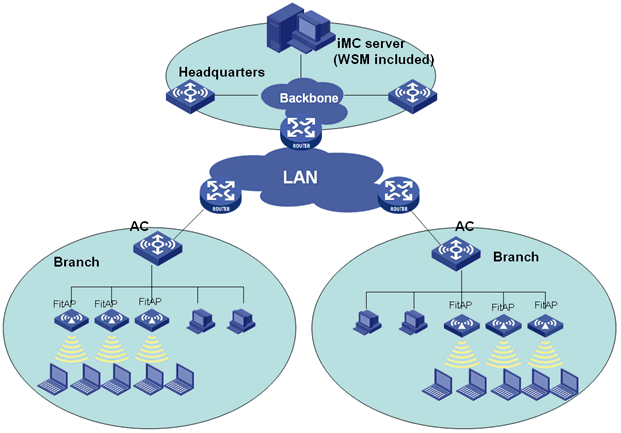
Before you create a new AC + fit APs network in WSM, complete the following tasks:
· Configure the AC to provide network access services.
· Connect fit APs to the access device, and make sure the fit APs and the AC can reach each other.
· Configure an SNMP community on the AC, and add the AC to the IMC platform.
As a best practice, use the following procedures to manage the AC + fit APs network:
1. (Optional.) Add fit AP groups, and classify the fit APs into groups. For more information about configuring fit AP groups, see "Managing fit AP templates."
2. Configure global parameters for the AC. For more information, see "Configuring AC global parameters."
3. (Optional.) Add radio policies for the AC, and bind the radio policies to the radios on each managed fit AP so the radios can operate correctly. For more information, see "Configuring a radio policy."
4. (Optional.) Configure the same parameters for multiple radios in batches on the AC to reduce repetitive operations and improve efficiency. For more information, see "Configuring radios in batches."
5. Add WLAN logical interfaces for the AC and modify the port security mode and VLAN for them. For more information, see "Configuring WLAN logical interfaces."
6. Add service policies for the AC, bind service policies to WLAN logical interfaces of the AC, and bind service policies to radios of the fit APs so that the fit APs can provide wireless services. For more information, see "Configuring a service policy."
To manage an existing wireless network, you only need to manage the ACs in WSM without creating an AC + fit AP network in WSM. In the current WSM version, only some of the functions are available to Comware 7 ACs.
Viewing the AC list
The AC List page displays information about all managed ACs in IMC.
The AC list page also offers access to the following features:
· Configuring service policies.
· Configuring radio policies.
· Configuring wireless logical interfaces.
· Managing MP policies.
· Managing mesh profiles.
· Managing mesh interfaces
To view the AC list:
1. Click the Service tab.
2. From the navigation tree, select WLAN Manager > Resource Management > ACs.
The AC List page displays all ACs.
AC List
¡ Status—Current alarm status of the AC.
¡ Device Label—Device label that identifies the AC in the IMC platform. Click the device label of an AC to view its details.
The device labeled with the icon ![]() represents a central AC. You can view the
local ACs managed by a central AC on its brief information page and view the connection between
central ACs and local ACs in the wireless device topology.
represents a central AC. You can view the
local ACs managed by a central AC on its brief information page and view the connection between
central ACs and local ACs in the wireless device topology.
¡ Model—Model of the AC.
¡ IP Address—Management IP address of the AC.
¡ Total APs—Total number of fit APs managed by the AC. Click the number to view all the managed fit APs.
¡ Online APs—Number of online fit APs managed by the AC. Click the number to view all the managed online fit APs.
¡ Online Clients—Number of clients that are associated with the fit APs managed by the AC. Click the number to view all of the online clients.
¡ Last Sync Time—Time when the AC configuration was last synchronized.
¡ Sync Result—Last synchronization result, Succeeded, Synchronizing, or Failed.
¡ Operation—Click the Operation icon ![]() for the AC.
for the AC.
The operational tasks provided in the Operation menu are:
- Service Policy
- Radio Policy
- Fit AP List
- Wireless Logical Interface Configuration
- RADIUS Policy
- MP Policy Management
- Mesh Profile Management
- Mesh Interface Management
- View Topology
- History Information
- Threshold Configuration
- Ping
- TraceRoute
- Open Web Manager
- Telnet
- SSH
|
|
IMPORTANT: · The Operation menu for a Comware-based AC is different from that of an MSM series AC. · The Threshold Configuration option appears only when Clients Associated with AC (Minor) or Clients Associated with AC (Major) is enabled. For more information, see "Setting alarm thresholds." |
If the AC List contains enough entries, the following navigational aids are displayed:
· Click the Next Page
icon ![]() to page
forward in the AC List.
to page
forward in the AC List.
· Click the Last Page
icon ![]() to page
forward to the end of the AC List.
to page
forward to the end of the AC List.
· Click the Previous Page
icon ![]() to page
backward in the AC List.
to page
backward in the AC List.
· Click the First Page
icon ![]() to page
backward to the front of the AC List.
to page
backward to the front of the AC List.
Click 8, 15, 50, 100, or 200 at the upper right of the AC List to specify the number of items you want to display on each page.
You can sort the AC List by every field except the Operation field. Click the column label to sort the list by the selected field. The column label allows you to toggle between the sort options specific to each field.
Synchronizing ACs
WSM supports synchronizing AC configuration automatically or manually. By default, IMC automatically synchronizes ACs every 2 hours (see HPEH3C IMC v7.3 Enterprise and Standard Platform Administrator Guide). You can also manually synchronize ACs as needed.
To manually synchronize ACs:
1. Click the Service tab.
2. From the navigation tree, select WLAN Manager > Resource Management > ACs.
The AC List page displays all ACs.
3. Select the ACs you want to synchronize.
4. Click Synchronize to start synchronizing the selected ACs.
The synchronization process takes several minutes. To view the last synchronization time and synchronization results, refresh the page or enter the page again after synchronization is complete.
Querying ACs
WSM provides basic query and advanced query. Basic query criteria include several key parameters for quick searches. Advanced query offers various query criteria for precise matching.
For more information, see "Querying ACs."
Viewing brief information about an AC
1. Click the Service tab.
2. From the navigation tree, select WLAN Manager > Resource Management > ACs.
The AC List page displays all ACs.
3. Click the device label of an AC.
The page displays brief information about the AC.
Device Information
¡ Device Label—Device label of the AC.
¡ Device Status—Alarm status of the AC.
¡ IP Address—IPv4 address of the AC.
¡ Device Model—Device model of the AC.
The Wireless Service Information area provides AP information, client information, and global parameter information for the AC. For more information, see "Viewing detailed information about an AC."
The Client Count graph and the AP Bandwidth graph provide online client and AP bandwidth trends. For more information, see "Client Count" and "AP Bandwidth."
The Local AC list displays all local ACs managed by the central AC. This list is displayed only for a central AC. For more information, see "Configuring a central AC."
The Wireless Service Alarm area provides information about the alarms that the AC generates. For more information, see "Viewing wireless service alarms."
The Detected APs area provides information about APs detected by sensors managed by the AC. For more information, see "Detected APs."
Viewing detailed information about an AC
1. Click the Service tab.
2. From the navigation tree, select WLAN Manager > Resource Management > ACs.
The AC List page displays all ACs.
3. Click the device label of an AC.
4. In the top right corner of the brief AC information page, click More Detailed.
The AC details page opens.
This information describes only wireless service information about the AC. For other information displayed on the AC details page, see H3C IMC v7.3 Enterprise and Standard Platform Administrator Guide.
5. Click the Wireless Service Information tab.
Global Parameter Information
¡ Max APs—Maximum number of fit APs that can be managed by the AC.
¡ Max Clients—Maximum number of clients that can be associated with the fit APs managed by the AC.
¡ Control Channel Security Scheme—Indicates whether CAPWAP control tunnel packets are encrypted. Options are Plaintext and Ciphertext.
¡ Data Channel Security Scheme—Indicates whether CAPWAP data tunnel packets are encrypted. Options are Plaintext and Ciphertext.
¡ Traffic Load Balancing Threshold (%)—Traffic threshold at the wireless side for fit APs managed by the AC when load balancing is enabled on the AC. It is the ratio of traffic at the wireless side of a fit AP to the throughput of the AP expressed in percentage. When the traffic of a fit AP managed by the AC reaches the threshold, the fit AP rejects requests from any client and the AC informs another fit AP to accept those requests. If this field displays N/A, traffic mode load balancing is disabled.
¡ Client Load Balancing Threshold—Client threshold for fit APs managed by the AC when load balancing is enabled on the AC. When the number of clients associated to a fit AP managed by the AC reaches the threshold, the fit AP rejects requests from any client and the AC informs another fit AP to accept those requests. If this field displays N/A, client mode load balancing is disabled.
¡ Auto AP—Select the auto AP function as needed. Options are Enable and Disable. The auto AP feature enables an AC to automatically associate with the fit APs of the model specified in the template configured on the AC. For more information, see "Adding a fit AP template."
¡ Scan Mode—Channel scanning mode for the fit APs. Options are Active and Passive.
In Active mode, a fit AP can operate as a client to send probe requests to another fit AP during the scanning process.
In Passive mode, the fit APs do not send any probe requests during the scanning process.
¡ Scan Channel—Channel scanning mode: All or Auto. All indicates the fit APs scan all channels. Auto indicates the fit APs scan channels allowed in the country or region to which the connected AC belongs.
¡ Country/Region Code—Code of the country or district to which the AC belongs, such as US (United States) and CN (China). The working channel of a radio varies with country codes. If the channel scanning mode is Auto, the AC uses the country code to determine the channels to be scanned for the fit APs.
¡ MKD-ID—MKD MAC address used by the AC for key exchange.
¡ Troubleshooting—Whether the troubleshooting function is enabled. For more information, see "Troubleshooting."
¡ Modify—Click the Modify icon ![]() to modify global parameters of the AC as needed. For more
information, see "Configuring AC global parameters."
to modify global parameters of the AC as needed. For more
information, see "Configuring AC global parameters."
AP Information
¡ Online Fit APs—Number of online fit APs managed by the AC. Click the number to view all the managed online fit APs.
¡ Offline Fit APs—Number of offline fit APs managed by the AC. Click the number to view all the managed offline fit APs.
¡ Online/P Fit APs—Number of fit APs that have established primary tunnels with the current AC. Such fit APs are managed by the AC. Click the number to view all fit APs that have established primary tunnels with the current AC. In an AC backup environment, a fit AP can connect to at most two ACs to establish a primary tunnel with one AC and a backup tunnel with the other.
¡ Online/S Fit APs—Number of fit APs that have established backup tunnels with the current AC. Such fit APs are not managed by the AC. Click the number to view all fit APs that have established backup tunnels with the current AC. In an AC backup environment, a fit AP can connect to at most two ACs to establish a primary tunnel with one AC and a backup tunnel with the other.
¡ Auto Fit APs—Number of auto fit APs associated with the AC. Click the number to view all auto fit APs.
¡ View All—Click View All to display all fit APs managed by the AC. On the Fit AP List, operators can add, delete, import, and export fit APs, locate fit APs on a map, and synchronize AP labels. For more information, see "Viewing the fit AP list."
Client Information
¡ Online Clients—Number of clients that are associated with the fit APs managed by the AC. Click the number to view all the online clients.
¡ Associated Clients—Number of successful associations between clients and fit APs.
¡ Associated Failures—Number of failed associations between clients and fit APs.
¡ Re-associated Clients—Number of reassociations between clients and fit APs.
¡ Rejected Clients—Number of rejected associations between clients and fit APs.
¡ Exceptional Deauthenticated Clients—Number of exceptional disassociations between clients and fit APs.
Configuring AC global parameters
You can access the AC Parameter Configuration page from the AC details page or the configuration management page. The following information uses the AC details page as an example.
To configure AC global parameters:
1. Click the Service tab.
2. From the navigation tree, select WLAN Manager > Resource Management > ACs.
The AC List page displays all ACs.
3. Click the device label of an AC.
4. Use one of these methods to configure the AC parameters:
¡ Click
the Modify icon ![]() for the global parameter information.
for the global parameter information.
¡ Click the Global Configuration link in the AC Configuration area to the right of the page.
The AC Global Parameter Configuration page opens.
5. Set the following parameters:
¡ Load Balancing—Enable or disable load balancing. Options are Traffic Threshold, Client Count Threshold, and No Threshold.
- If you select Traffic Threshold, traffic load balancing is enabled. Enter the traffic load balancing threshold for an AP and the traffic load balancing gap between two APs. The traffic load balancing threshold is the ratio of traffic at the wireless side of a fit AP to the throughput of the AP expressed in percentage. When either the threshold or the gap is reached for a fit AP, the fit AP rejects requests from any new clients and the AC informs another fit AP to accept those requests.
- If you select Client Count Threshold, client load balancing is enabled. Enter the client load balancing threshold and the client load balancing gap between two APs. When either the threshold or the gap is reached for a fit AP, the fit AP rejects requests from any new clients and the AC informs another fit AP to accept those requests.
- If you select No Threshold, load balancing is disabled.
¡ Auto AP—Enable or disable the auto AP function. Options are Enable and Disable.
If you select Enable, the AC automatically associates with the fit APs of the model specified in the template configured on the AC.
If you select Disable, the AC does not automatically associate with the fit APs even if a template that contains the model is configured on the AC.
For more information about auto fit AP templates, see "Adding a fit AP template."
¡ Scan Mode—Select the channel scanning mode. Options are Active and Passive.
- Active—Fit APs operate as clients to send probe requests to other fit APs during the scanning process.
- Passive—Fit APs do not send any probe requests during the scanning process.
¡ Scan Channel—Select the channels to be scanned. Options are All and Auto.
- All—Fit APs scan all channels.
- Auto—Fit APs scan channels allowed in the country or region to which the connected AC belongs. The default option is Auto.
¡ Country/Region Code—Select the code of the country or district to which the AC belongs, such as US (United States) and CN (China). The working channel of a radio varies with country codes. If the channel scanning mode is Auto, the country code of the AC determines the channels scanned by the fit APs.
¡ MKD-ID—Enter the Mesh Key Distributor (MKD) for key exchange. The default value is 000F-E200-0001. Make sure the MAC address configured is unused and has the correct vendor specific part. The MAC address of an AC cannot be configured as the MKD ID.
¡ Synchronize AC Configuration—Synchronize the global configuration to other ACs in the AC group to which the current AC belongs. To apply the global configuration only to the current AC, do not select this option. This option is available only when the AC belongs to at least one AC group.
¡ AC Group—Select an AC group. Options include all AC groups to which the current AC belongs. This option is available only when Synchronize AC Configuration is selected.
¡ Layer2 Isolation—Enable or disable Layer 2 isolation. Configure this parameter in combination with the user-isolation vlan command executed on the AC. With the function enabled, clients in the permitted MAC address list can communicate with other clients in the same VLAN. For example, if you execute the user-isolation vlan 1 permit-mac 0000-1111-2222 command on the AC and enable Layer 2 isolation, client 0000-1111-2222 can visit other clients in VLAN 1, but other clients cannot visit each other.
¡ Troubleshooting—To enable the troubleshooting function, select this option. WSM collects syslogs that ACs send to the IMC platform for troubleshooting analysis.
|
|
NOTE: For clients to access the network after you enable Layer 2 isolation, first add the MAC address of the gateway to the permitted MAC address list. |
6. Click OK.
Configuring a radio policy
A radio policy is a collection of radio parameters and takes effect after it is bound to a radio.
To facilitate creating radio policies, WSM provides the radio policy template management function. For more information, see "Managing radio policy templates."
You can access the Radio Policy Management page from the AC list page, the AC details page, or the configuration management page. The following information uses the AC list page as an example.
Viewing the radio policy list
2. From the navigation tree, select WLAN Manager > Resource Management > ACs.
The AC List page displays all ACs.
3. Click the Operation icon ![]() for an AC.
for an AC.
4. From the menu, select Radio Policy.
The Radio Policy Management page opens.
The Radio Policy List displays all radio policy information of the AC.
Radio Policy List
¡ Policy Name—Name of the radio policy.
¡ Beacon Interval (TU)—Interval at which an AP sends a beacon frame.
¡ DTIM Interval—Number of beacon intervals an AP waits before it sends buffered multicast and broadcast frames.
¡ RTS Threshold (bytes)—Length of frames for which the request to send (RTS) method is used.
¡ Fragment Threshold (bytes)—Maximum length of frames that can be transmitted without fragmentation.
¡ Rx Lifecycle (ms)—Interval for an AP to hold a received frame in its buffer memory.
¡ Operation—Click the Operation icon ![]() for the radio policy to display the operation menu.
for the radio policy to display the operation menu.
The operational tasks provided in the Operation menu are Modify, Delete, and Bound Radios.
Radio List
¡ Admin Status—Administrative state for the radio. Options are Up and Down.
¡ Radio ID—ID of the radio.
¡ AP Template Name—Name of the template used by the AP to which the radio belongs.
¡ Radio Type—Select a radio type. Options are:
- 802.11a
- 802.11b
- 802.11g
- 802.11bg
- 802.11at
- 802.11an
- 802.11gn
- 802.11n (2.4GHz)
- 802.11bgn
- 802.11n
- 802.11n (5GHz)
¡ Policy Name—Name of the radio policy that has been bound to a radio.
¡ Delete—Click the Delete icon ![]() to delete the radio.
to delete the radio.
5. Click Related Operations, and then select one of the following to enter the configuration page:
¡ Configuration Management
¡ AP Configuration
¡ Configure Radio in Batches
¡ Wireless Logical Interface Configuration
¡ Service Policy Management
If the Radio Policy List contains enough entries, the following navigational aids are displayed:
· Click the Next Page
icon ![]() to page
forward in the Radio Policy List.
to page
forward in the Radio Policy List.
· Click the Last Page
icon ![]() to page
forward to the end of the Radio Policy List.
to page
forward to the end of the Radio Policy List.
· Click the Previous Page
icon ![]() to page
backward in the Radio Policy List.
to page
backward in the Radio Policy List.
· Click the First Page
icon ![]() to page
backward to the front of the Radio Policy List.
to page
backward to the front of the Radio Policy List.
Viewing radio policy details
1. Click the Service tab.
2. From the navigation tree, select WLAN Manager > Resource Management > ACs.
The AC List page displays all ACs.
3. Click the Operation
icon ![]() for an
AC.
for an
AC.
4. From the menu, select Radio Policy.
The Radio Policy Management page opens and displays all radio policies and their bound radios of the AC.
5. Click the name of a radio policy to view details.
Radio Policy Details
¡ Policy Name—Name of the radio policy.
¡ Beacon Interval (TU)—Interval at which an AP sends a beacon frame.
¡ DTIM Interval—Number of beacon intervals an AP waits before it sends buffered multicast and broadcast frames.
¡ RTS Threshold (bytes)—Length of frames for which the request to send (RTS) method is used.
¡ Fragment Threshold (bytes)—Maximum length of frames that can be transmitted without fragmentation.
¡ Short Frame Retransmission Threshold—Maximum number of attempts to transmit a frame shorter than the RTS threshold.
¡ Long Frame Retransmission Threshold—Maximum number of attempts to transmit a frame larger than the RTS threshold.
¡ Rx Lifecycle (ms)—Interval for an AP to hold a received frame in its buffer memory.
¡ Max Clients—Maximum number of clients that can be associated with a radio that uses the policy.
6. Click Close.
Adding a radio policy
You can add a radio policy for an AC by using either of the following methods:
· Normal method—Add a radio policy in Radio Policy Management.
· Express method—Add a radio policy by using the template. For more information about radio policy templates, see "Managing radio policy templates."
Normal method
To add a radio policy by using the normal method:
1. Click the Service tab.
2. From the navigation tree, select WLAN Manager > Resource Management > ACs.
The AC List page displays all ACs.
3. Click the Operation
icon ![]() for an
AC.
for an
AC.
4. From the menu, select Radio Policy.
The Radio Policy Management page opens and displays all the radio policy information of the AC.
5. Click Add Policy.
The page for adding a radio policy opens.
6. Set the following parameters:
¡ Policy Name—Enter a name to uniquely identify the radio policy on the AC.
¡ Beacon Interval (TU)—Enter the interval for an AP to send beacon frames.
¡ DTIM Interval—Enter the number of beacon intervals an AP waits before it sends buffered multicast and broadcast frames. The value is in the range of 1 to 31. The default value is 1, which equals 102400 microseconds. The AP sends buffered broadcast/multicast frames when the DTIM counter reaches the configured value.
¡ RTS Threshold (bytes)—Enter the length of frames for which the request to send (RTS) method is used. Set a rational value to effectively avoid data sending collisions in a WLAN. If you set a small value, RTS packets are sent frequently, consuming more of the available bandwidth. However, the system can recover quickly from interference or collisions.
¡ Fragment Threshold (bytes)—Enter the maximum length of frames that can be transmitted without fragmentation. A packet that exceeds the specified fragment threshold is fragmented.
¡ Short Frame Retransmission Threshold—Enter the maximum number of attempts to transmit a frame shorter than the RTS threshold.
¡ Long Frame Retransmission Threshold—Enter the maximum number of attempts to transmit a frame larger than the RTS threshold.
¡ Rx Lifecycle (ms)—Enter the interval for an AP to hold a received frame in its buffer memory.
¡ Max Clients—Enter the maximum number of clients that can be associated with a radio that uses the policy.
¡ Synchronize AC Configuration—Apply the radio policy to all ACs in the specified AC group. To apply the radio policy only to the current AC, do not select this option. This option is available only when the AC belongs to at least one AC group.
¡ AC Group—Select an AC group. Options are all AC groups to which the current AC belongs. This option is available only when Synchronize AC Configuration is selected.
7. Click OK.
Express method
To add a radio policy by using the express method:
1. Click the Service tab.
2. From the navigation tree, select WLAN Manager > Resource Management > ACs.
The AC List page displays all ACs.
3. Click the Operation
icon ![]() for an AC.
for an AC.
4. From the menu, select Radio Policy.
The Radio Policy Management page opens and displays all the radio policy information of the AC on the Radio Policy List.
5. Click Select Template.
All radio policy templates in WSM are displayed.
Select Radio Policy Template
¡ Policy Name—Name of the radio policy.
¡ Beacon Interval—Interval for an AP to send beacon frames.
¡ DTIM Interval—Number of beacon intervals an AP waits before it sends buffered multicast and broadcast frames.
¡ RTS Threshold—Length of frames for which the request to send (RTS) method is used.
¡ Fragment Threshold—Maximum length of frames that can be transmitted without fragmentation.
¡ Rx Lifecycle—Interval for the AP to hold a received frame in its buffer memory.
6. Select the radio policy template you want to use.
7. Click Next.
8. Modify the following parameters as needed:
¡ Policy Name—Enter the name of the radio policy. The default value is the name of the selected radio template.
¡ Synchronize AC Configuration—Apply the radio policy to all ACs in the specified AC group. To apply the radio policy only to the current AC, do not select this option. This option is available only when the AC belongs to at least one AC group.
¡ AC Group—Select an AC group. Options are all AC groups to which the current AC belongs. This option is available only when Synchronize AC Configuration is selected.
9. Click OK.
The Result List page opens, displaying operation results for adding the radio policy.
10. Click Back to return to the Radio Policy Management page of the current AC.
Modifying a radio policy
The default radio policy default_rp cannot be modified.
To modify a user-defined radio policy:
1. Click the Service tab.
2. From the navigation tree, select WLAN Manager > Resource Management > ACs.
The AC List page displays all ACs.
3. Click the Operation
icon ![]() for an AC.
for an AC.
4. From the menu, select Radio Policy.
The Radio Policy Management page opens and displays all the radio policy information of the AC on the Radio Policy List.
5. Click the Operation
icon ![]() for a radio
policy.
for a radio
policy.
6. From the menu, select Modify.
The page for modifying radio policies opens.
7. Set the radio policy parameters as needed. For more information, see "Adding a radio policy."
The radio policy name cannot be modified.
8. Click OK.
Viewing radios bound to a radio policy
1. Click the Service tab.
2. From the navigation tree, select WLAN Manager > Resource Management > ACs.
The AC List page displays all ACs.
3. Click the Operation
icon ![]() for an
AC.
for an
AC.
4. From the menu, select Radio Policy.
The Radio Policy Management page opens and displays all the radio policy information of the AC on the Radio Policy List.
5. Click the Operation
icon ![]() for a
radio policy.
for a
radio policy.
6. From the menu, select Bound Radios.
The Radio List dialog box opens.
The Bound Radio List displays information about all radios bound to the current radio policy. Operators can unbind radios as needed and synchronize the most recent bound radio list to all ACs in an AC group. For more information, see "Binding a radio policy to radios."
Binding a radio policy to radios
1. Click the Service tab.
2. From the navigation tree, select WLAN Manager > Resource Management > ACs.
The AC List page displays all ACs.
3. Click the Operation
icon ![]() for an
AC.
for an
AC.
4. From the menu, select Radio Policy.
The Radio Policy Management page opens and displays all the radio policy information of the AC on the Radio Policy List.
5. Select the radio policy you want to bind.
6. Click Add in the Radio List area.
The Select Radios dialog box opens.
7. Specify one or more of the following query criteria to search for the radios you want to configure:
¡ AP Label—Enter the label of the fit AP to which the radio belongs. WSM supports fuzzy matching for this field.
¡ AP Name—Enter the name of the fit AP to which the radio belongs. WSM supports fuzzy matching for this field
¡ Serial Number—Enter the serial number of the fit AP to which the radio belongs. WSM supports fuzzy matching for this field
¡ Radio Type—Select a radio type. Options are:
- 802.11a
- 802.11b
- 802.11g
- 802.11bg
- 802.11at
- 802.11an
- 802.11gn
- 802.11n (2.4GHz)
- 802.11bgn
- 802.11n
- 802.11n (5GHz)
¡ Admin Status—Select an administrative state for the radio. Options are Unlimited, Up, and Down.
¡ Radio Policy Name—Enter the name of the radio policy bound to the radio. WSM supports fuzzy matching for this field.
¡ Location—Enter or select the name of the location view to which the fit AP belongs. WSM supports fuzzy matching for this field.
An empty field or a field that is set to Unlimited does not serve as a query criterion.
8. Click Query.
The Radio List displays all radios matching the query criteria. Click Reset to clear the query criteria and display all radios.
9. Select the radios to be bound to the radio policy.
10. Click OK to close the Select Device window.
The Radio List displays all selected radios.
The Result List page opens, displaying the successful and failed binding operations. If a failure occurs, click the Details icon in the Operation Result column to identify the reason for the failure.
Unbinding a radio policy from radios
The default radio policy default_rp is bound to all radios and cannot be unbound.
To unbind radios from a user-defined radio policy:
1. Click the Service tab.
2. From the navigation tree, select WLAN Manager > Resource Management > ACs.
The AC List page displays all ACs.
3. Click the Operation
icon ![]() for an AC.
for an AC.
4. From the menu, select Radio Policy.
The Radio Policy Management page opens and displays all the radio policy information of the AC on Radio Policy List.
5. Click the Operation
icon ![]() for a
radio policy.
for a
radio policy.
6. From the menu, select Bound Radios.
The Radio List dialog box opens.
7. Select the radios you want to unbind.
8. Set the following parameters as needed:
¡ Synchronize AC Configuration—Unbind radios from the radio policy on all ACs in the specified AC group. To unbind radios from the radio policy only on the current AC, do not select this option. This option is available only when the AC belongs to at least one AC group.
¡ AC Group—Select an AC group. Options are all AC groups to which the current AC belongs. This option is available only when Synchronize AC Configuration is selected.
9. Click Unbind.
The Result List page opens and displays the successful and failed unbinding operations. Click the Details icon in the Operation column to identify the reason for the failure.
10. Click Back to close the dialog box.
Deleting a radio policy
Deleting a radio policy deletes all information related to the radio policy. You cannot delete the default radio policy default_rp and any radio policy that is bound to a radio.
To delete a radio policy:
1. Click the Service tab.
2. From the navigation tree, select WLAN Manager > Resource Management > ACs.
The AC List page displays all ACs.
3. Click the Operation
icon ![]() for an AC.
for an AC.
4. From the menu, select Radio Policy.
The Radio Policy Management page opens and displays all the radio policy information of the AC on the Radio Policy List.
5. Click the Operation
icon ![]() for a
radio policy.
for a
radio policy.
6. From the menu, select Delete.
A confirmation dialog box opens.
7. Click OK.
Configuring radios in batches
To ease radio configuration and reduce repetitive operations, WSM allows operators to configure public parameters for multiple radios of the fit APs managed by an AC in batches.
You can access the Radio Batch Configuration page from the AC details page or the configuration management page. The following information uses the AC list page as an example.
To configure radios in batches:
1. Click the Service tab.
2. From the navigation tree, select WLAN Manager > Resource Management > ACs.
The AC List page displays all ACs.
3. Click the device label of an AC.
4. In the Wireless Service area to the right of the page, click Radio Batch Configuration.
The Radio Batch Configuration page opens.
5. Set the following parameters:
¡ Radio Type—Select a radio type. Options are:
- 802.11a
- 802.11b
- 802.11g
- 802.11bg
- 802.11at
- 802.11an
- 802.11gn
- 802.11n (2.4GHz)
- 802.11bgn
- 802.11n
- 802.11n (5GHz)
- 802.11ac
¡ Max Transmission Power (dBm)—Enter the maximum transmit power of the radio.
¡ Admin Status—Select an administrative state for the radio. Options are Up and Down.
¡ Channels in Use—Select the working channel of the radio. The value range depends on the radio type. If you select Auto, the AC assigns an optimum channel to the radio.
¡ Preamble Type—Select the preamble type for the fit AP. Options are Short and Long. Short means the fit AP transmits frames with either a short preamble or long preamble. Long means the fit AP only transmits frames with a long preamble. You can configure this option if you select the 802.11b, 802.11g, and 802.11gn radio type.
¡ Radio Policy—Select a radio policy to be bound to the radio. Options are all existing radio policies in WSM.
¡ Synchronize AC Configuration—Synchronize the global configuration to other ACs in the AC group to which the current AC belongs. To apply the global configuration only to the current AC, do not select this option. This option is available only when the AC belongs to at least one AC group.
6. Click Add in the Radio List area.
The Select Device dialog box opens.
7. Specify one or more of the following query criteria to search for the radios you want to configure:
¡ AP Label—Enter the label of the fit AP to which the radio belongs. WSM supports fuzzy matching for this field.
¡ AP Name—Enter the name of the fit AP to which the radio belongs. WSM supports fuzzy matching for this field.
¡ Serial Number—Enter the serial number of the fit AP to which the radio belongs. WSM supports fuzzy matching for this field.
¡ Radio Type—Select a radio type. Options are 802.11a, 802.11b, 802.11g, 802.11gn, and 802.11an.
¡ Admin Status—Select an administrative state for the radio. Options are Unlimited, Up, and Down.
¡ Radio Policy Name—Enter the name of the radio policy bound to the radio. WSM supports fuzzy matching for this field.
¡ Location—Enter or select the name of the location view to which the fit AP belongs. WSM supports fuzzy matching for this field.
An empty field or a field that is set to Unlimited does not serve as a query criterion.
8. Click Query.
The Radio List displays all radios matching the query criteria.
Click Reset to clear the query criteria and display all radios.
9. Select the radios you want to configure.
10. Click OK to close the Select Device window.
The Radio List displays all selected radios.
11. Click OK.
The Result List page opens, displaying the configuration result of each radio.
12. Click Back to return to the radio batch configuration page.
|
|
NOTE: As a best practice to avoid configuration failures, configure radios in batches on fit APs of the same model. |
Configuring WLAN logical interfaces
Service policies are bound to the WLAN logical interfaces of an AC. A WLAN logical interface can be bound only to one service policy.
You can access the WLAN Logical Interface Configuration page from the AC list page, the AC details page, or the configuration management page. The following information uses the AC list page as an example.
Viewing the WLAN logical interface list
1. Click the Service tab.
2. From the navigation tree, select WLAN Manager > Resource Management > ACs.
The AC List page displays all ACs.
3. Click the Operation
icon ![]() for an
AC.
for an
AC.
4. From the menu, select Wireless Logical Interface Configuration.
The Wireless Logical Interface Configuration page opens and displays all the WLAN logical interface information of the AC on the Wireless Logical Interface List.
WLAN Logical Interface List
¡ Description—Interface description in the WLAN-ESS interface ID format.
¡ SSID—Unique SSID of the service policy bound to the WLAN logical interface. Click the name to view its details.
¡ Port Security Mode—Port security mode for the WLAN logical interface. Options are:
- noRestrictions
- mac-and-psk
- mac-authentication
- mac-else-userlogin-secure
- mac-else-userlogin-secure-ext
- psk
- userlogin-secure
- userlogin-secure-ext
- userlogin-secure-or-mac
- userlogin-secure-or-mac-ext
- userlogin-secure-ext-or-psk
- userlogin-with OUI
¡ VLAN—VLAN to which the WLAN logical interface belongs.
¡ Operation—Click the Operation icon ![]() for the WLAN logical interface to display the operation menu.
for the WLAN logical interface to display the operation menu.
The operational tasks provided in the Operation menu are Delete Interface, Modify Port Security, and Modify VLAN.
5. Click Related Operations, and then select Configuration Management, Configure Radio Batches or Service Policy Management to enter the configuration page.
If the Wireless Logical Interface List contains enough entries, the following navigational aids are displayed:
· Click the Next Page
icon ![]() to page
forward in the Wireless Logical Interface List.
to page
forward in the Wireless Logical Interface List.
· Click the Last Page
icon ![]() to page
forward to the end of the Wireless Logical Interface List.
to page
forward to the end of the Wireless Logical Interface List.
· Click the Previous Page
icon ![]() to page
backward in the Wireless Logical Interface List.
to page
backward in the Wireless Logical Interface List.
· Click the First Page
icon ![]() to page
backward to the front of the Wireless Logical Interface List.
to page
backward to the front of the Wireless Logical Interface List.
To configure the number of items you want to display on each page, click 8, 15, 50, 100, or 200 at the upper right of the Wireless Logical Interface List.
You can sort the Wireless Logical Interface List by every field except the Operation field. Click the column label to sort the list by the selected field. The column label allows you to toggle between the sort options specific to each field.
Querying WLAN logical interfaces
1. Click the Service tab.
2. From the navigation tree, select WLAN Manager > Resource Management > ACs.
The AC List page displays all ACs.
3. Click the Operation
icon ![]() for an
AC.
for an
AC.
4. From the menu, select Wireless Logical Interface Configuration.
The Wireless Logical Interface Configuration page opens and displays all the WLAN logical interface information of the AC on WLAN Logical Interface List.
5. Specify one or both of the following query criteria:
¡ Description—Enter a description for the interface. WSM supports fuzzy matching for this field.
¡ SSID—Enter the SSID of the AC. WSM supports fuzzy matching for this field.
An empty field or a field that is set to Unlimited does not serve as a query criterion.
6. Click Query.
The Device List displays all radio interfaces matching the query criteria.
Click Reset to clear the query criteria and display all radio interfaces.
Adding a WLAN logical interface
1. Click the Service tab.
2. From the navigation tree, select WLAN Manager > Resource Management > ACs.
The AC List page displays all ACs.
3. Click the Operation
icon ![]() for an
AC.
for an
AC.
4. From the menu, select Wireless Logical Interface Configuration.
The Wireless Logical Interface Configuration page opens and displays all the WLAN logical interface information of the AC on the Wireless Logical Interface List.
5. Click Add Interface.
The page for adding WLAN logical interfaces opens.
6. Set the following parameters:
¡ Interface ID—Enter the ID of the WLAN logical interface. For example, if you add a WLAN logical interface with the ID 50, the interface description for the interface is WLAN-ESS50.
¡ Synchronize AC Configuration—Apply the WLAN logical interface setting to all ACs in the specified AC group. To apply the WLAN logical interface setting only to the current AC, do not select this option. This option is available only when the AC belongs to at least one AC group.
¡ Cancel Shake Hands—Select this option to disable the 802.1X handshake function.
¡ AC Group—Select an AC group. Options are all AC groups to which the current AC belongs. This option is available only when Synchronize AC Configuration is selected.
7. Click OK.
The Adding Interface Result page opens, displaying the operation result for adding the WLAN logical interface and the result for AC synchronization.
8. Click Back to return to the WLAN Logical Interface Configuration page.
Modifying the port security mode for a WLAN logical interface
To modify the port security mode of a WLAN logical interface that has been bound to a service policy, first set the Interface ID of the WLAN logical interface to –1 on the Modify Service Policy page.
To modify the port security mode for a WLAN logical interface:
1. Click the Service tab.
2. From the navigation tree, select WLAN Manager > Resource Management > ACs.
The AC List page displays all ACs.
3. Click the Operation
icon ![]() for an AC.
for an AC.
4. From the menu, select Wireless Logical Interface Configuration.
The Wireless Logical Interface Configuration page opens and displays all the WLAN logical interface information of the AC on the Wireless Logical Interface List.
5. Use one of these methods to modify the port security:
¡ Click
the Operation icon ![]() for a WLAN logical interface, and select Modify
Port Security from the menu.
for a WLAN logical interface, and select Modify
Port Security from the menu.
¡ Select the WLAN logical interface for which you want to modify the port security mode, and click Modify Port Security on the WLAN Logical Interface List.
The Modify Port Security page opens.
6. Set the following parameters:
¡ Port Security Mode—Select a port security mode for the WLAN logical interface. Options are:
- noRestrictions
- mac-and-psk
- mac-authentication
- mac-else-userlogin-secure
- mac-else-userlogin-secure-ext
- psk
- userlogin-secure
- userlogin-secure-ext
- userlogin-secure-or-mac
- userlogin-secure-or-mac-ext
- userlogin-secure-ext-or-psk
- userlogin-with OUI
When the encryption mode for a service policy is Clear or the security IE is None, the port security mode WLAN logical interfaces cannot be mac-and-psk, psk, or userlogin-secure-ext-or-psk.
When the encryption mode for a service policy is Crypto and the security IE is RSN or WPA, the port security mode WLAN logical interfaces can only be mac-and-psk, psk, userlogin-secure-ext-or-psk, or userlogin-secure-ext, and the key negotiation type must be 11Key.
Table 7 Port security mode
|
Port security mode |
Key parameters |
|
noRestrictions |
No key parameters are needed. |
|
mac-and-psk |
· Key negotiation type—Options are None and 11Key. · PSK type—Options are None, Pass-Phrase, and Raw-Key. · PSK—Enter the PSK value. If you select None for PSK type, this field is not needed. |
|
mac-authentication |
No key parameters are needed. |
|
mac-else-userlogin-secure |
No key parameters are needed. |
|
mac-else-userlogin-secure-ext |
No key parameters are needed. |
|
psk |
· Key negotiation type—Options are None and 11Key. · PSK type—Options are None, Pass-Phrase, and Raw-Key. · PSK—Enter the PSK value. If you select None for PSK type, this field is not needed. |
|
userlogin-secure |
No key parameters are needed. |
|
userlogin-secure-ext |
Key negotiation type. Options are None and 11Key. |
|
userlogin-secure-or-mac |
No key parameters are needed. |
|
userlogin-secure-or-mac-ext |
No key parameters are needed. |
|
userlogin-secure-ext-or-psk |
· Key negotiation type—Options are None and 11Key. · PSK type—Options are None, Pass-Phrase, and Raw-Key. · PSK—Enter the PSK value. If you select None for PSK type, this field is not needed. |
|
userlogin-with OUI |
No key parameters are needed. |
¡ Cancel Shake Hands—Select this option to disable the 802.1X handshake function.
¡ Synchronize AC Configuration—Apply the port security mode setting to all ACs in the specified AC group. To apply the port security mode setting only to the current AC, do not select this option. This option is available only when the AC belongs to at least one AC group.
¡ AC Group—Select an AC group. Options are all AC groups to which the current AC belongs. This option is available only when Synchronize AC Configuration is selected.
7. Click OK.
The Result List page opens, displaying the operation result for modifying the port security mode for the selected WLAN logical interface and the result for AC synchronization.
8. Click Back to return to the WLAN Logical Interface Configuration page.
Modifying the VLAN to which WLAN logical interfaces belong
1. Click the Service tab.
2. From the navigation tree, select WLAN Manager > Resource Management > ACs.
The AC List page displays all ACs.
3. Click the Operation
icon ![]() for an
AC.
for an
AC.
4. From the menu, select Wireless Logical Interface Configuration.
The Wireless Logical Interface Configuration page opens and displays all the WLAN logical interface information of the AC on WLAN Logical Interface List.
5. Use one of the following methods to modify the VLAN:
¡ Click
the Operation icon ![]() for a WLAN logical interface, and select Modify
VLAN from the menu.
for a WLAN logical interface, and select Modify
VLAN from the menu.
¡ Select the WLAN logical interfaces for which you want to modify VLAN, and click Modify VLAN on the WLAN Logical Interface List.
The Modify VLAN page opens.
6. Set the following parameters:
¡ VLAN—Select a VLAN. Options are all VLANs created on the current AC.
¡ Synchronize AC Configuration—Apply the VLAN setting to all ACs in the specified AC group. To apply the VLAN setting only to the current AC, do not select this option. This option is available only when the AC belongs to at least one AC group.
¡ AC Group—Select an AC group. Options are all AC groups to which the current AC belongs. This option is available only when Synchronize AC Configuration is selected.
7. Click OK.
The Result List page opens, displaying the operation results for modify the VLAN to which the selected interfaces belong and the result for AC synchronization.
8. Click Back to return to the WLAN Logical Interface Configuration page.
Deleting WLAN logical interfaces
To delete a WLAN logical interface that has been bound to a service policy, first set the Interface ID of the WLAN logical interface to –1 on the Modify Service Policy page.
To delete a WLAN logical interface:
1. Click the Service tab.
2. From the navigation tree, select WLAN Manager > Resource Management > ACs.
The AC List page displays all ACs.
3. Click the Operation
icon ![]() for an
AC.
for an
AC.
4. From the menu, select Wireless Logical Interface Configuration.
The Wireless Logical Interface Configuration page opens and displays all the WLAN logical interface information of the AC on the WLAN Logical Interface List.
5. Click the Operation
icon ![]() for the
WLAN logical interface you want to delete, and then select Delete Interface from the
menu.
for the
WLAN logical interface you want to delete, and then select Delete Interface from the
menu.
Or
Select the WLAN logical interfaces you want to delete, and then click Delete Interface on the WLAN Logical Interface List.
A confirmation dialog box opens.
6. Click OK.
Configuring a service policy
A service policy is a collection of WLAN access parameters that enable a fit AP to provide WLAN access services after the policy is bound to a radio of the fit AP. Different radios can use the same service policy, and each radio can be bound to multiple service policies.
To facilitate creating service policies, WSM provides the service policy template management function. For more information, see "Managing service policy templates."
You can access the Service Policy Management page from the AC list page, the AC details page, or the configuration management page. The following information uses the AC list page as an example.
Viewing the service policy list
1. Click the Service tab.
2. From the navigation tree, select WLAN Manager > Resource Management > ACs.
The AC List page displays all ACs.
3. Click the Operation
icon ![]() for an
AC.
for an
AC.
4. From the menu, select Service Policy.
The Service Policy Management page opens.
Two lists are available on the page: the Service Policy List that displays all service policy information of the AC, and the Radio List that displays all radios that are bound to the service policies.
On the Service Policy List, you can add and modify a service policy, select a service policy template, refresh the Service Policy List, delete a service policy, view radios bound to a service policy, and bind radios to a service policy in batches.
Service Policy List
¡ Policy ID—ID of the service policy.
¡ SSID—SSID of the service policy.
¡ Encryption Mode—Encryption mode for the service policy. This field does not appear for Comware 7 ACs. Options are:
- Clear Mode—No data packets need to be encrypted.
- Crypto Mode—All data packets need to be encrypted.
¡ Hide SSID—Indicates whether to provide the SSID in beacon frames sent by the fit AP. If this parameter is selected, clients cannot obtain the SSID from the beacon frames and must configure the SSID before accessing the wireless network. If this parameter is not selected, clients can obtain the SSID from the beacon frames to access the wireless network.
¡ Enable Status—Indicates whether the service policy is enabled. Options are:
- Enable—Indicates the service policy is enabled on the AC and the AC can provide services.
- Disable—Indicates the service policy is not enabled on the AC and the AC cannot provide services.
- Not Ready—Indicates the service policy is being deployed to the AC and the AC cannot provide services.
¡ Authentication Mode—Authentication mode of the service policy. This field does not appear for Comware 7 ACs. Options are:
- Open System—Allows all clients requesting for authentication to directly pass authentication.
- Shared Key—Requires clients to use the same shared key as that configured on the device. Specify Shared Key only when you select WEP40, WEP104, or WEP128 as the cipher suite.
- All—Allows clients to use either the Open System mode or the Shared Key mode as needed.
¡ Operation—Click the Operation icon ![]() for the service policy to display the operation menu
for the service policy to display the operation menu
The operational tasks provided in the Operation menu are modifying and deleting specified service policies and viewing information about radios bound to the specified service policy.
On the Radio List, you can add or delete a radio, or remove all radios.
Radio List
¡ Admin Status—Administrative state for the radio. Options are Up and Down.
¡ Radio ID—ID of the radio.
¡ AP Template Name—Name of the template of the AP to which the radio belongs.
¡ Radio Type—Radio type. Options are:
- 802.11a
- 802.11b
- 802.11g
- 802.11gn
- 802.11an
¡ Policy Name—Name of the radio policy that is bound to the radio.
¡ Delete—Click the Delete icon ![]() to delete the radio.
to delete the radio.
5. Click Related Operations, and then select Configuration Management or Wireless Logical Interface Configuration to enter the configuration page.
If the Service Policy List contains enough entries, the following navigational aids are displayed:
· Click the Next Page
icon ![]() to page
forward in the Service Policy List.
to page
forward in the Service Policy List.
· Click the Last Page
icon ![]() to page
forward to the end of the Service Policy List.
to page
forward to the end of the Service Policy List.
· Click the Previous Page
icon ![]() to page
backward in the Service Policy List.
to page
backward in the Service Policy List.
· Click the First Page
icon ![]() to page
backward to the front of the Service Policy List.
to page
backward to the front of the Service Policy List.
To configure the number of items you want to display on each page, click 8, 15, 50, 100, or 200 at the upper right of the Service Policy List.
Viewing service policy details
2. From the navigation tree, select WLAN Manager > Resource Management > ACs.
The AC List page displays all ACs.
3. Click the Operation
icon ![]() for an
AC.
for an
AC.
4. From the menu, select Service Policy.
The Service Policy Management page displays all the service policy information of the AC on the Service Policy List.
5. Click the ID of a service policy to view its basic information.
For Comware 5 ACs:
Service policy basic information
¡ Policy ID—ID of the service policy.
¡ SSID—SSID of the service policy.
¡ Encryption Mode—Encryption mode for the service policy. Options are:
- Clear—No data packets need to be encrypted.
- Crypto—All data packets need to be encrypted.
¡ Hide SSID—Indicates whether to provide the SSID in beacon frames sent by the fit AP. If this parameter is selected, clients cannot obtain the SSID from the beacon frames and must configure the SSID before accessing the wireless network. If this parameter is not selected, clients can obtain the SSID from the beacon frames to access the wireless network.
¡ Enable Status—Indicates whether the service policy is enabled. Options are:
- Enable—Indicates the service policy is enabled on the AC and the AC can provide services.
- Disable—Indicates the service policy is not enabled on the AC and the AC cannot provide services.
- Not Ready—Indicates the service policy is being deployed to the AC and the AC cannot provide services.
¡ Authentication Mode—Authentication mode of the service policy. Options are:
- Open System—Allows all clients requesting for authentication to directly pass authentication.
- Shared Key—Requires clients to use the same shared key as that configured on the device. Specify Shared Key only when you select WEP40, WEP104, or WEP128 as the cipher suite.
- All—Allows clients to use either the Open System mode or the Shared Key mode.
¡ Interface ID—ID of the WLAN logical interface that the service policy is bound to.
¡ Interface Type—Type of the interface bound to the service policy, which is always WLAN-ESS.
¡ Max Clients—Maximum number of clients that can use the service policy to associate with fit APs.
¡ Layer2 Isolation—Enable or disable Layer 2 isolation. Configure this parameter in combination with the user-isolation vlan command executed on the AC. With the function enabled, clients in the permitted MAC address list can communicate with other clients in the same VLAN. For example, if you execute the user-isolation vlan 1 permit-mac 0000-1111-2222 command on the AC and enable Layer 2 isolation, client 0000-1111-2222 can visit other clients in VLAN 1, but other clients cannot visit each other.
|
|
NOTE: For clients to access the network after Layer 2 isolation is enabled, first add the MAC address of the gateway into the permitted MAC address list. |
¡ Synchronize AC Configuration—Apply the service policy to all ACs in the specified AC group of the AC. If this option is not selected, the service policy is applied only to the current AC.
¡ AC Group—AC group to which the service policy is applied. This field does not appear if the Synchronize AC Configuration option is not selected.
Security Information
¡ Security IE—Security IE used in the beacon frames and probe responses sent by the fit AP. Options are: None, RSN, WPA, and All.
None indicates no security IE is configured.
All indicates both RSN and WPA are configured. For more information about RSN and WPA, see the related device manual.
¡ Cipher Suite—Cipher suite used in data frame encryption and decryption. Options are:
- TKIP
- CCMP
- WEP40
- WEP104
- WEP128
¡ Key Index—Authentication key index for clients.
¡ Key—Authentication key for clients.
For Comware 7 ACs:
Service policy basic information
¡ Policy ID—ID of the service policy.
¡ SSID—SSID of the service policy.
¡ Hide SSID—Indicates whether to provide the SSID in beacon frames sent by the fit AP. If this parameter is selected, clients cannot obtain the SSID from the beacon frames and must configure the SSID before accessing the wireless network. If this parameter is not selected, clients can obtain the SSID from the beacon frames to access the wireless network.
¡ Enable Status—Indicates whether the service policy is enabled. Options are:
- Enable—Indicates the service policy is enabled on the AC and the AC can provide services.
- Disable—Indicates the service policy is not enabled on the AC and the AC cannot provide services.
- Not Ready—Indicates the service policy is being deployed to the AC and the AC cannot provide services.
¡ Max Clients—Maximum number of clients that can use the service policy to associate with fit APs.
¡ Synchronize AC Configuration—Apply the service policy to all ACs in the specified AC group of the AC. If this option is not selected, the service policy is applied only to the current AC.
¡ AC Group—AC group to which the service policy is applied. This field does not appear if the Synchronize AC Configuration option is not selected.
Security Information
¡ Security IE—Security IE used in the beacon frames and probe responses sent by the fit AP. Options are None, RSN, WPA, and All.
None indicates no security IE is configured.
All indicates both RSN and WPA are configured. For more information about RSN and WPA, see the related device manual.
¡ Cipher Suite—Cipher suite used in data frame encryption and decryption. Options are:
- TKIP
- CCMP
- WEP40
- WEP104
- WEP128
¡ Key—Authentication key for clients. This field appears only when Cipher Suite is set to WEP40, WEP104, or WEP128.
¡ AKM Mode—Authentication and key management mode. Options are MAC, dot1x, and psk.
¡ PSK—Pre-shared key. This field appears only when AKM Mode is set to psk.
6. Click Close.
Adding a service policy
You can add a service policy for an AC in the following methods:
· Normal method—Add a service policy in Service Policy Management.
· Express method—Select a service policy template and add a service policy by using the template. For more information about service policy templates, see "Managing service policy templates."
You can use only the normal method to add service policies for Comware 7 ACs.
For service policy configuration to succeed, configure the security IE and cipher suite for the AC through the CLI or Web interface before configuring security information for a service policy.
Using the normal method (Comware 5 AC)
1. Click the Service tab.
2. From the navigation tree, select WLAN Manager > Resource Management > ACs.
The AC List page displays all ACs.
3. Click the Operation
icon ![]() for an
AC.
for an
AC.
4. From the menu, select Service Policy.
The Service Policy Management page displays all the service policy information of the AC on the Service Policy List.
5. Click Add Policy.
The page for adding a service policy opens.
6. Set the following parameters:
¡ Policy ID—Enter an ID of the service policy to uniquely identify the service policy on the AC.
¡ Enable—Select this option only if you want to enable the service policy immediately after it is applied to the AC.
¡ SSID—Enter the SSID of the service policy.
¡ Coded Format—Select the coded format for the SSID. Options are default, GB2312, and UTF-8.
¡ Encryption Mode—Select the encryption mode for the service policy. Options are:
- Clear—No data packets need to be encrypted.
- Crypto—All data packets need to be encrypted.
¡ Hide SSID—Select this option to hide the SSID in beacon frames sent by the fit AP. When this parameter is selected, clients cannot obtain the SSID from the beacon frames and must configure the SSID before accessing the wireless network. If this parameter is not selected, clients can obtain the SSID from the beacon frames.
¡ Authentication Mode—Select the authentication mode of the service policy. When the encryption mode is Clear, the authentication mode can only be Open System. When the encryption mode is Crypto, the authentication mode options are Open System, Shared Key, and All.
- Open System—Allows all clients requesting for authentication to directly pass authentication.
- Shared Key—Requires clients to use the same shared key as that configured on the device. Specify Shared Key only when you select WEP40, WEP104, or WEP128 as the cipher suite.
- All—Allows clients to use either the Open System mode or the Shared Key mode as needed.
¡ Binding Interface—This parameter is forcibly selected and requires you to bind a WLAN logical interface to the service policy to be added.
¡ Interface ID—Enter the interface ID to be bound to the service policy. If the ID represents a non-existent WLAN logical interface, WSM automatically creates the WLAN logical interface for the AC. For service policy configuration to succeed, ensure that the WLAN logical interface is not bound to any other service policy.
¡ Interface Type—Select the type of the interface to be bound to the service policy, which is always WLAN-ESS.
¡ Max Clients—Maximum number of clients that can use the service policy to associate with fit APs.
¡ Synchronize AC—Apply the service policy to all ACs in the specified AC group. To apply the service policy only to the current AC, do not select this option. This option is available only when the AC belongs to at least one AC group.
¡ AC Group—Select an AC group. Options are all AC groups to which the current AC belongs. This option is available only when Synchronize AC Configuration is selected.
¡ Layer2 Isolation—Enable or disable Layer 2 isolation. This parameter must be configured in combination with the user-isolation vlan command executed on the AC. If the function is enabled, clients in the permitted MAC address list can communicate with other clients in the same VLAN. For example, if you execute the user-isolation vlan 1 permit-mac 0000-1111-2222 command on the AC and enable Layer 2 isolation, client 0000-1111-2222 can visit other clients in VLAN 1, but other clients cannot visit each other.
|
|
NOTE: For clients to access the Internet after layer 2 isolation is enabled, first add the MAC address of the gateway into the permitted MAC address list. |
¡ Client Forwarding Mode—Select a forwarding mode from the list. Options are remote, local, and policy-based. If remote is selected, data packets are forwarded by the AC. If local is selected, data packets are forwarded by APs managed by the AC. If policy-based is selected, data packets are forwarded based on the configured forwarding policy.
7. If Crypto is selected as the Encryption Mode, set the following security parameters as needed:
¡ Security IE—Select the security IE used in the beacon frames and probe responses sent by the fit AP. Options are:
- None—Indicates no security IE is configured.
- RSN—A robust security network is a security network that only allows the creation of robust security network associations to provide greater protection than WPA.
- WPA—WPA operates in either WPA-PSK (or Personal) mode or WPA-802.1X (or Enterprise) mode. In Personal mode, a pre-shared key or pass-phrase is used for authentication. In Enterprise mode, 802.1X and RADIUS servers and the EAP are used for authentication.
- All—Indicates both RSN and WPA are configured.
For more information about RSN and WPA, see the related device manual.
¡ Cipher Suite—Select the cipher suite used for data frame encryption and decryption. Options are TKIP, CCMP, WEP40, WEP104, and WEP128. You can set the key index and key only when you select WEP40, WEP104, or WEP128. You cannot select WEP40, WEP104, and WEP128 at the same time.
- WEP—Includes WEP40, WEP104, and WEP128. They are all static WEP encryption mechanisms. A WEP40 key is 40 bits, a WEP104 key is 104 bits, and a WEP128 key is 128 bits. WEP uses RC4 encryption and requires that all clients accessing the wireless network use the same key.
- TKIP—Temporal Key Integrity Protocol uses the RC4 algorithm as WEP does, but provides more secure protection for WLAN.
- CCMP—Counter mode with CBC-MAC Protocol is a Counter-Mode/CBC-MAC mechanism based on advanced encryption standard (AES) to provide high security.
¡ Key Index—Enter the authentication key index for clients.
¡ Key—Enter the authentication key for clients.
For WEP40, the key is a string of 5 alphanumeric characters.
For WEP104, the key is a string of 13 alphanumeric characters.
For WEP128, the key is a string of 16 alphanumeric characters.
8. Click OK.
Using the normal method (Comware 7 AC)
1. Click the Service tab.
2. From the navigation tree, select WLAN Manager > Resource Management > ACs.
The AC List page displays all ACs.
3. Click the Operation
icon ![]() for an
AC.
for an
AC.
4. From the menu, select Service Policy.
The Service Policy Management page displays all the service policy information of the AC on the Service Policy List.
5. Click Add Policy.
The page for adding a service policy opens.
6. Set the following parameters:
Basic Information
¡ Policy ID—Enter an ID for the service policy to uniquely identify the service policy on the AC.
¡ Enable—Select this option only if you want to enable the service policy immediately after it is applied to the AC.
¡ SSID—Enter the SSID of the service policy.
¡ Coded Format—Select the coded format for the SSID. Options are default, GB2312, and UTF-8.
¡ Hide SSID—Select this option to hide the SSID in beacon frames sent by the fit AP. When this parameter is selected, clients cannot obtain the SSID from the beacon frames and must configure the SSID before accessing the wireless network. If this parameter is not selected, clients can obtain the SSID from the beacon frames.
¡ Max Clients—Enter the maximum number of clients that can use the service policy to associate with fit APs.
¡ Synchronize AC—Apply the service policy to all ACs in the specified AC group. To apply the service policy to only the current AC, do not select this option. This option is available only when the AC belongs to at least one AC group.
¡ AC Group—Select an AC group. Options are all AC groups to which the current AC belongs. This option is available only when Synchronize AC Configuration is selected.
Security Information
¡ Security IE—Select the security IE used in the beacon frames and probe responses sent by the fit AP. Options are:
- None—Indicates no security IE is configured.
- RSN—A robust security network is a security network that only allows the creation of robust security network associations to provide greater protection than WPA.
- WPA—Wi-Fi protected access, which uses more advanced encryption algorithms than WEP to secure wireless networks.
- All—Indicates both RSN and WPA are configured.
Table 8 lists security IE options and corresponding security information parameter settings.
Table 8 Security information settings
|
Security IE |
Security information parameters |
|
None |
· Cipher Suite—Select the cipher suite used for data frame encryption and decryption. Options are WEP40, WEP104, and WEP128. Only one option can be selected at a time. · Key—Enter the authentication key for clients. For WEP40, the key is a string of 5 alphanumeric characters. For WEP104, the key is a string of 13 alphanumeric characters. For WEP128, the key is a string of 16 alphanumeric characters. · AKM Mode—Select an authentication and key management mode to authenticate users and manage keys. Options are None and MAC. |
|
RSN |
· Cipher Suite—Select the cipher suite used for data frame encryption and decryption. Options are TKIP and CCMP. You can select both TKIP and CCMP. · AKM Mode—Select an authentication and key management mode to authenticate users and manage keys. Options are dot1x and psk. · PSK—Enter a pre-shared key when the AKM Mode is set to psk. |
|
WPA |
|
|
All |
Using the express method
1. Click the Service tab.
2. From the navigation tree, select WLAN Manager > Resource Management > ACs.
The AC List page displays all ACs.
3. Click the Operation
icon ![]() for an
AC.
for an
AC.
4. From the menu, select Service Policy.
The Service Policy Management page displays all the service policy information of the AC on the Service Policy List.
5. Click Select Template.
All service policy templates in WSM are displayed in the list.
Select Service Policy Template
¡ SSID—SSID of the service policy.
¡ Encryption Mode—Encryption mode for the service policy: Clear or Crypto. The Clear mode means no data packets need to be encrypted. The Crypto mode means all data packets need to be encrypted.
¡ Hide SSID—Indicates whether the SSID is hidden in beacon frames sent by the fit AP. When this parameter is selected, clients cannot obtain the SSID from the beacon frames and must configure the SSID before accessing the wireless network. If this parameter is not selected, clients can obtain the SSID from the beacon frames to access the wireless network.
¡ Authentication Mode—Authentication mode of the service policy. Options are:
- Open System—Allows all clients requesting for authentication to directly pass authentication.
- Shared Key—Requires clients to use the same shared key as that configured on the device. Specify Shared Key only when you select WEP40, WEP104, or WEP128 as the cipher suite.
- All—Allows clients to use either the Open System mode or the Shared Key mode as needed.
6. Select the service policy template you want to use.
7. Click Next.
Select Service Policy Template contents
¡ Synchronize AC Configuration—Apply the service policy to all ACs in the specified AC group. To apply the global configuration only to the current AC, do not select this option. This option is available only when the AC belongs to at least one AC group.
¡ AC Group—Select an AC group. Options are all AC groups to which the current AC belongs. This option is available only when Synchronize AC Configuration is selected.
¡ Policy ID—Enter an ID of the service policy to uniquely identify the service policy on the AC.
¡ Interface ID—Enter the interface ID to be bound to the service policy. If the ID represents a non-existent WLAN logical interface, WSM automatically creates the WLAN logical interface for the AC. For service policy configuration to succeed, ensure that the WLAN logical interface is not bound to any other service policy.
8. Click OK.
The Result List page opens, displaying operation results for adding service policies.
9. Click Back to return to the Service Policy Management page of the current AC.
Modifying a service policy
For service policy configuration to succeed, configure the security IE and cipher suite for the AC through the CLI or Web interface before configuring security information for a service policy.
To modify a service policy:
1. Click the Service tab.
2. From the navigation tree, select WLAN Manager > Resource Management > ACs.
The AC List page displays all ACs.
3. Click the Operation
icon ![]() for an
AC.
for an
AC.
4. From the menu, select Service Policy.
The Service Policy Management page displays all the service policy information of the AC on Service Policy List.
5. Click the Operation
icon ![]() for a
service policy.
for a
service policy.
6. From the menu, select Modify.
The Modify Service Policy page opens.
7. Modify the service policy parameters as needed, see "Using the normal method (Comware 5 AC)" and "Using the normal method (Comware 7 AC)."
A service policy ID cannot be modified.
Viewing radios bound to a service policy
1. Click the Service tab.
2. From the navigation tree, select WLAN Manager > Resource Management > ACs.
The AC List page displays all ACs.
3. Click the Operation
icon ![]() for an
AC.
for an
AC.
4. From the menu, select Service Policy.
The Service Policy Management page displays all the service policy information of the AC on the Service Policy List.
5. Click the Operation
icon ![]() for a
service policy.
for a
service policy.
6. From the menu, select Bound Radios.
The Radio List dialog box opens.
The Bound Radios list displays information about all radios bound to the current service policy.
Bound Radio List
¡ Radio ID—ID of the radio.
¡ Admin Status—Administrative state for the radio. Options are Up and Down.
¡ Radio Type—Radio type. Options are:
- 802.11a
- 802.11b
- 802.11g
- 802.11gn
- 802.11an
¡ AP Label—Label of the AP to which the radio belongs.
¡ AP Name—Name of the AP to which the radio belongs.
¡ SN—Serial number of the AP to which the radio belongs.
¡ Radio Policy Name—Name of the radio policy to which the radio is bound.
7. Click Close to close the dialog box.
Binding radios to service policies
1. Click the Service tab.
2. From the navigation tree, select WLAN Manager > Resource Management > ACs.
The AC List page displays all ACs.
3. Click the Operation
icon ![]() for an
AC.
for an
AC.
4. From the menu, select Service Policy.
The Service Policy Management page displays all the service policy information of the AC on Service Policy List.
5. Select the target service policies.
6. Click Add in the Radio List area.
The Select Device dialog box opens.
7. Specify one or more of the following query criteria to search for the radios you want to configure:
¡ AP Label—Enter the label of the fit AP to which the radio belongs. WSM supports fuzzy matching for this field.
¡ AP Name—Enter the name of the fit AP to which the radio belongs. WSM supports fuzzy matching for this field.
¡ Serial Number—Enter the serial number of the fit AP to which the radio belongs. WSM supports fuzzy matching for this field.
¡ Radio Type—Select a radio type. Options are:
- 802.11a
- 802.11b
- 802.11g
- 802.11gn
- 802.11an.
¡ Admin Status—Select an administrative state for the radio. Options are Up and Down.
¡ Radio Policy Name—Enter the name of the radio policy bound to the radio. WSM supports fuzzy matching for this field.
¡ Location—Enter or select the name of the location view to which the fit AP belongs. WSM supports fuzzy matching for this field.
An empty field or a field that is set to Unlimited does not serve as a query criterion.
8. Click Query.
The Radio List displays all radios matching the query criteria.
Click Reset to clear the query criteria and display all radios.
9. Select the radios you want to bind to service policies.
10. Click OK to close the Select Device window. The Radio List displays all selected radios.
11. Click Bind Policy.
The Result List page opens, displaying the operation results for binding service polices to radios.
Unbinding radios from service policies
You can unbind radios to multiple service polices in batches or unbind radios to one service policy. Unbinding radios in up state from a service policy interrupts the services provided by the radios and logs off all clients associated with the radios.
To unbind radios from multiple service policies in batches:
1. Click the Service tab.
2. From the navigation tree, select WLAN Manager > Resource Management > ACs.
The AC List page displays all ACs.
3. Click the Operation
icon ![]() for an
AC.
for an
AC.
4. From the menu, select Service Policy.
The Service Policy Management page displays all the service policy information of the AC on the Service Policy List.
5. Select the target service policies.
6. Click Add in the Radio List area.
The Select Device dialog box opens.
7. Specify one or more of the following query criteria to search for the radios you want to configure:
¡ AP Label—Enter the label of the fit AP to which the radio belongs. WSM supports fuzzy matching for this field.
¡ AP Name—Enter the name of the fit AP to which the radio belongs. WSM supports fuzzy matching for this field. For example, if you enter B, all radios on fit APs whose names contain B are queried.
¡ Serial Number—Enter the serial number of the fit AP to which the radio belongs. WSM supports fuzzy matching for this field.
¡ Radio Type—Select a radio type. Options are:
- 802.11a
- 802.11b
- 802.11g
- 802.11gn
- 802.11an.
¡ Admin Status—Select an administrative state for the radio. Options are Up and Down.
¡ Radio Policy Name—Enter the name of the radio policy bound to the radio. WSM supports fuzzy matching for this field.
¡ Location—Enter or select the name of the location view to which the fit AP belongs. WSM supports fuzzy matching for this field.
An empty field or a field that is set to Unlimited does not serve as a query criterion.
8. Click Query.
The Radio List displays all radios matching the query criteria.
Click Reset to clear the query criteria and display all radios.
9. Select the radios you want to unbind from service policies.
10. Click OK to close the Select Radios window.
The Radio List displays all selected radios.
11. Click Unbind.
WSM checks the radios in the list one by one. If any binding to the service policy is found, WSM removes the binding. After the process is complete, the Result List page opens, displaying the operation results for removing bindings between service policies and radios.
To remove bindings between radios and a service policy:
12. Click the Service tab.
13. From the navigation tree, select WLAN Manager > Resource Management > ACs.
The AC List page displays all ACs.
14. Click the Operation
icon ![]() for an
AC.
for an
AC.
15. From the menu, select Service Policy.
The Service Policy Management page displays all the service policy information of the AC on the Service Policy List.
16. Click the Operation
icon ![]() for a
service policy.
for a
service policy.
17. From the menu, select Bound Radios.
The Radio List dialog box opens.
18. Select the radios to be unbound.
19. Set the following parameters:
¡ Synchronize AC Configuration—Unbind radios from the service policy on all ACs in the specified AC group. To unbind radios from the service policy only on the current AC, do not select this option. This option is available only when the AC belongs to at least one AC group.
¡ AC Group—Select an AC group. Options are all AC groups to which the current AC belongs. This option is available only when Synchronize AC Configuration is selected.
20. Click Unbind.
The Result List page opens, displaying the operation results for unbinding radios from the service policy.
21. Click Back to close the dialog box.
Deleting a service policy
To delete a service policy that has been bound to radios, first unbind the radios from the service policy.
To delete a service policy:
1. Click the Service tab.
2. From the navigation tree, select WLAN Manager > Resource Management > ACs.
The AC List page displays all ACs.
3. Click the Operation
icon ![]() for an
AC.
for an
AC.
4. From the menu, select Service Policy.
The Service Policy Management page displays all the service policy information of the AC on the Service Policy List.
5. Click the Operation
icon ![]() for a
service policy.
for a
service policy.
6. From the menu, select Delete.
A confirmation dialog box opens.
Viewing the online fit APs managed by an AC
1. Click the Service tab.
2. From the navigation tree, select WLAN Manager > Resource Management > ACs.
The AC List page displays all ACs.
3. Use one of the following methods:
¡ Click the number in the Online APs column of an AC.
¡ Click the device label of an AC, and in the AP Information area of the Device Details page that opens, click the number of Online APs.
The Fit AP List page displays all online fit APs managed by the AC. For more information about the Fit AP List, see "Viewing the fit AP list."
Viewing the online clients
This function allows you to view all online clients that are associated with the fit APs managed by an AC.
To view the online clients:
1. Click the Service tab.
2. From the navigation tree, select WLAN Manager > Resource Management > ACs.
The AC List page displays all ACs.
3. Use one of the following methods:
¡ Click the number in the Online Clients column of an AC.
¡ Click the device label of an AC, and in the Client Information area of the Device Details page that opens, click the number for Online Clients.
The Online Client List displays all online clients that are associated with the fit APs managed by the AC. For more information about the Online Client List, see "Viewing the client list."
Monitoring the client quantity
1. Click the Service tab.
2. From the navigation tree, select WLAN Manager > Resource Management > ACs.
The AC List page displays all ACs.
3. Click Client Monitor.
The page for monitoring the client quantity opens.
4. Click Select ACs in the top right corner of the page.
The AC list appears.
5. Select a maximum of five ACs to be monitored.
6. Click OK.
The line chart provides the quantity of clients connected to the monitored ACs in real time.
Viewing MP policies of an AC
1. Click the Service tab.
2. From the navigation tree, select WLAN Manager > Resource Management > ACs.
The AC List page displays all ACs.
3. Use one of the following methods:
¡ Click
the Operation icon ![]() for an AC, and then select MP Policy
Management from the menu.
for an AC, and then select MP Policy
Management from the menu.
¡ Click the device label of an AC, and in the Mesh Management area to the right of the page, click the MP Policy Management link.
The MP Policy Management page opens.
All mesh policy information of the AC appears in the MP Policy List. You can add, modify, delete mesh policies, view mesh policy details, and bind radios to or unbind radios from mesh policies. For more information, see "Managing MP policies."
Viewing mesh profiles of an AC
1. Click the Service tab.
2. From the navigation tree, select WLAN Manager > Resource Management > ACs.
The AC List page displays all ACs.
3. Use one of the following methods:
¡ Click
the Operation icon ![]() for an AC, and then select Mesh Profile
Management from the menu.
for an AC, and then select Mesh Profile
Management from the menu.
¡ Click the device label of an AC, and in the Mesh Management area to the right of the page, click the Mesh Profile Management link.
The Mesh Profile Management page opens.
All mesh profile information of the AC appears in the Mesh Profile List. You can add, modify, delete mesh profiles, view mesh profile details, and bind radios to or unbind radios from mesh profiles. For more information, see "Managing MP policies."
Viewing mesh interfaces of an AC
1. Click the Service tab.
2. From the navigation tree, select WLAN Manager > Resource Management > ACs.
The AC List page displays all ACs.
3. Use one of the following methods:
¡ Click
the Operation icon ![]() for an AC, and then select Mesh Interface
Management from the menu.
for an AC, and then select Mesh Interface
Management from the menu.
¡ Click the device label of an AC, and in the Mesh Management area to the right of the page, click the Mesh Interface Management link.
The Mesh Interface Management page opens.
All mesh interface information of the AC appears in the Mesh Interface List. You can add, modify, delete mesh interfaces, modify port security settings, or modify VLAN for the mesh interfaces. For more information, see "Managing mesh interfaces."
Viewing AC history information
This function enables you to view AC traffic and rate history information in the last hour, last day, last week, last month, or in a user-defined time range.
· Traffic statistics—View statistics collection start time and end time, traffic sent, traffic received, and total traffic.
· Rate statistics—View transmit and receive rate trend graph, peak transmit rate, peak receive rate, average transmit rate, and transmit and receive rate at the specified statistics collection time.
You can access the History Information page of an AC from the AC list page or the AC details page. The following information uses the AC list page as an example.
To view AC history information:
1. Click the Service tab.
2. From the navigation tree, select WLAN Manager > Resource Management > ACs.
The AC List page displays all ACs.
3. Click the Operation
icon ![]() for a
Comware-based AC and select History Information.
for a
Comware-based AC and select History Information.
The History Information dialog box opens.
4. Select a statistics type from the Statistics list.
Options are Traffic and Rate. The default option is Traffic.
5. Click 1h, 1d, 1w, 1m, or 1y to specify the time range for statistics collection.
Or click Custom. In the Custom window that opens, enter a start time and end time, or click the field next to Start Time/End Time to select the start time/end time from the calendar that appears, in the YYYY-MM-DD hh:mm format.
Statistics within the specified time range are displayed.
¡ Traffic Statistics
The unit of traffic changes with the amount of traffic sent or received.
If you select Traffic, the following information appears:
- Start Time—Start time for statistics collection, in the format YYYY-MM-DD hh:mm:ss.
- End Time—End time for statistics collection, in the format YYYY-MM-DD hh:mm:ss.
- Transmitted Traffic (B)—Total traffic sent by the AC within the specified time range. The measurement unit automatically changes as the data changes.
- Received Traffic (B)—Total traffic received by the AC within the specified time range. The measurement unit automatically changes as the data changes.
- Total Traffic (B)—Total traffic sent and received by the AC within the specified time range. The value is calculated based on statistics and might be slightly different from the actual value. The measurement unit automatically changes as the data changes.
¡ Rate Statistics
The unit of rates changes with the value of the rates.
If you select Rate, the following information appears:
- Transmission and Reception Rate Trend graph—Trend of the transmit and receive rates of the AC within the data collection time range. The x coordinate represents the time and the y coordinate represents the transmit and receive rates.
- Peak Transmission Rate (bps)—Maximum transmit rate for the AC in the statistics collection time range. The measurement unit automatically changes as the data changes.
- Peak Reception Rate (bps)—Maximum receive rate for the AC in the statistics collection time range. The measurement unit automatically changes as the data changes.
- Average Transmission Rate (bps)—Average transmit rate for the AC in the statistics collection time range. The measurement unit automatically changes as the data changes.
- Average Reception Rate (bps)—Average receive rate for the AC in the statistics collection time range. The measurement unit automatically changes as the data changes.
¡ Rate Details
Click Rate at the top of the trend graph to display the Details window.
- Time—Time when statistics are collected, in the format YYYY-MM-DD hh:mm:ss.
- Transmission Rate (bps)—Transmit rate of the AC at the specified time.
- Reception Rate (bps)—Receive rate of the AC at the specified time.
Configuring load balancing groups
WLAN load balancing applies mainly to high-density WLAN networks to dynamically adjust loads among APs to ensure adequate bandwidth for clients.
To balance loads among the radios of different APs, you can add them to the same load balancing group. The radios in a load balancing group can carry out either session-mode or traffic-mode load balancing as configured.
A radio in a load balancing group starts load balancing when the maximum threshold and gap are reached on it. The radio does not accept any association requests unless the load decreases below the maximum threshold or the gap is less than the maximum gap.
If a client has been denied more than the specified maximum times, the AP considers that the client is unable to associate to any other AP and accepts the association request from the client.
For the load balancing group to take effect, enable Load Balancing Limit and set related thresholds before configuring a load balancing group for an AC. The radios that are not added to any load balancing group do not carry out load balancing.
Viewing the load balancing group list
1. Click the Service tab.
2. From the navigation tree, select WLAN Manager > Resource Management > ACs.
The AC List page displays all ACs.
3. Click the device label of an AC.
4. In the AC Configuration area to the right of the page, click the Load Balance Group link.
The Load Balance Group List page opens.
Load Balance Group List
¡ ID—ID of the load balancing group.
¡ Description—Description for the load balancing group.
¡ Modify—Click the Modify icon ![]() to modify the load balancing group.
to modify the load balancing group.
¡ Delete—Click the Delete icon ![]() to delete the load balancing group.
to delete the load balancing group.
If the Load Balance Group List contains enough entries, the following navigational aids are displayed:
· Click the Next Page
icon ![]() to page
forward in the Load Balance Group List.
to page
forward in the Load Balance Group List.
· Click the Last Page
icon ![]() to page
forward to the end of the Load Balance Group List.
to page
forward to the end of the Load Balance Group List.
· Click the Previous Page
icon ![]() to page
backward in the Load Balance Group List.
to page
backward in the Load Balance Group List.
· Click the First Page
icon ![]() to page
backward to the front of the Load Balance Group List.
to page
backward to the front of the Load Balance Group List.
Click 8, 15, 50, 100, or 200 at the upper right of the Load Balance Group List to configure the number of items per page you want to display.
You can sort the Load Balance Group List by the ID field. Click the column label to sort the list by the selected field. The column label allows you to toggle between the various sort options specific to each field.
Adding a load balancing group
1. Click the Service tab.
2. From the navigation tree, select WLAN Manager > Resource Management > ACs.
The AC List page displays all ACs.
3. Click the device label of an AC.
4. In the AC Configuration area to the right of the page, click Load Balance Group.
The load balancing group information of the AC appears in the Load Balance Group List.
5. Click Add.
The page for adding a load balancing group opens.
6. Set the following parameters:
¡ ID—Enter the ID of the load balancing group.
¡ Description—Enter a description for the load balancing group.
7. Click OK.
Modifying a load balancing group
1. Click the Service tab.
2. From the navigation tree, select WLAN Manager > Resource Management > ACs.
The AC List page displays all ACs.
3. Click the device label of an AC.
4. In the AC Configuration area to the right of the page, click Load Balance Group.
All the load balancing group information of the AC appears in the Load Balance Group List.
5. Click the Modify
icon ![]() for a
load balancing group.
for a
load balancing group.
The page for modifying a load balancing group opens.
6. Modify the following parameters:
¡ ID—Cannot be modified.
¡ Description—Enter a description for the load balancing group.
7. Click OK.
Deleting a load balancing group
1. Click the Service tab.
2. From the navigation tree, select WLAN Manager > Resource Management > ACs.
The AC List page displays all ACs.
3. Click the device label of an AC.
4. In the AC Configuration area to the right of the page, click Load Balance Group.
All the load balancing group information of the AC appears in the Load Balance Group List.
5. Click the Delete
icon ![]() for a
load balancing group.
for a
load balancing group.
A confirmation dialog box opens.
6. Click OK.
Viewing radios in a load balancing group
1. Click the Service tab.
2. From the navigation tree, select WLAN Manager > Resource Management > ACs.
The AC List page displays all ACs.
3. Click the device label of an AC.
4. In the AC Configuration area to the right of the page, click Load Balance Group.
All the load balancing group information of the AC appears in the Load Balance Group List.
5. Click the ID of the target load balancing group.
The Radio List page opens.
Radio List
¡ AP Label—Label of the fit AP to which the radio belongs.
¡ SN—Serial number of the fit AP to which the radio belongs.
¡ Radio ID—ID of the radio.
¡ Radio Type—Radio type. Options are:
- 802.11a
- 802.11b
- 802.11g
- 802.11gn
- 802.11an
¡ Delete—Click the Delete icon ![]() to delete the radio.
to delete the radio.
If the Radio List contains enough entries, the following navigational aids are displayed:
· Click the Next Page
icon ![]() to page
forward in the Radio List.
to page
forward in the Radio List.
· Click the Last Page
icon ![]() to page
forward to the end of the Radio List.
to page
forward to the end of the Radio List.
· Click the Previous Page
icon ![]() to page
backward in the Radio List.
to page
backward in the Radio List.
· Click the First Page
icon ![]() to page
backward to the front of the Radio List.
to page
backward to the front of the Radio List.
Click 8, 15, 50, 100, or 200 at the upper right of the Radio List to configure the number of items you want to display.
You can sort the Radio List by every field except the Delete field. Click the column label to sort the list by the selected field. The column label allows you to toggle between the sort options specific to each field.
Adding radios to a load balancing group
Radios added to a load balancing group belong to the fit APs managed by the same AC.
To add a radio to a load balancing group:
1. Click the Service tab.
2. From the navigation tree, select WLAN Manager > Resource Management > ACs.
The AC List page displays all ACs.
3. Click the device label of an AC.
4. In the AC Configuration area to the right of the page, click Load Balance Group.
All load balancing group information of the AC appears in the Load Balance Group List.
5. Click the ID of a load balancing group.
All radios in the load balancing group are displayed in the Load Balance Group Radio List.
6. Click Add in the Radio List area.
The Select Device dialog box opens.
7. Specify one or more of the following query criteria to search for the radios you want to configure:
¡ AP Label—Enter the label of the fit AP to which the radio belongs. WSM supports fuzzy matching for this field.
¡ AP Name—Enter the name of the fit AP to which the radio belongs. WSM supports fuzzy matching for this field
¡ Serial Number—Enter the serial number of the fit AP to which the radio belongs. WSM supports fuzzy matching for this field.
¡ Radio Type—Select a radio type. Options are:
- All
- 802.11a
- 802.11b
- 802.11g
- 802.11bg
- 802.11at
- 802.11gn
- 802.11an
- 802.11ac
- 802.11n (2.4GHz)
- 802.11bgn
- 802.11n
- 802.11n (5GHz)
- 802.11ac/n/a
- Wired
¡ Admin Status—Select an administrative state for the radio. Options are Up and Down.
¡ Radio Policy Name—Enter the name of the radio policy bound to the radio. WSM supports fuzzy matching for this field.
¡ Location—Enter or select the name of the location view to which the fit AP belongs. WSM supports fuzzy matching for this field.
An empty field or a field that is set to Unlimited does not serve as a query criterion.
8. Click Query.
The Radio List displays all radios matching the query criteria. Click Reset to clear the query criteria and display all radios.
9. Select the radios you want to add to the load balancing group.
10. Click OK to close the Select Device window.
The Radio List displays all selected radios.
11. Click OK.
Deleting radios from a load balancing group
1. Click the Service tab.
2. From the navigation tree, select WLAN Manager > Resource Management > ACs.
The AC List page displays all ACs.
3. Click the device label of an AC.
4. In the AC Configuration area to the right of the page, click Load Balance Group.
The load balancing group information of the AC appears in the Load Balance Group List.
5. Click the ID of the load balancing group from which you want to delete radios.
All radios in the load balancing group are displayed in the Radio List.
6. Use one of the following methods:
¡ Select one or more radios to be deleted, and then click Delete.
¡ Click
the Delete icon ![]() for a radio, and then click OK in the dialog
box.
for a radio, and then click OK in the dialog
box.
7. Click OK.
Viewing supported fit AP models
This function allows you to view fit AP models supported by the AC. The information displayed in the fit AP model list include AP model, name, number of radios and maximum number of clients that can be associated with a radio, vendor, CPU model and frequency, memory model and its size, and flash model and its size. This function enables administrators to quickly get information about all fit AP models supported by the AC, providing support for wireless network planning.
To view supported fit AP models:
1. Click the Service tab.
2. From the navigation tree, select WLAN Manager > Resource Management > ACs.
The AC List page displays all ACs.
3. Click the device label of an AC.
4. In the AC Configuration area to the right of the page, click the View Supported Fit AP Models link.
The List of Supported AP Models page opens and displays all fit AP models supported by the current AC are displayed on the list.
List of Supported AP Models
¡ Model—Model of the fit AP.
¡ Name—Alias of the fit AP model.
¡ Radios/Clients—Number of radios on the fit AP and the maximum number of clients that can be associated with the fit AP.
¡ Vendor—Vendor of the fit AP, which is always H3C.
¡ CPU Model/Frequency—CPU model and frequency of the fit AP.
¡ Memory Model/Size—Memory model and capacity of the fit AP.
¡ Flash Model/Size—Flash model and capacity of the fit AP.
|
|
NOTE: You can sort the List of Supported AP Models by model, alias, and vendor. Click the column label to sort the list by the selected field. The column label allows you to toggle between the various sort options specific to each field. |
Viewing CAPWAP tunnel information
Control And Provisioning of Wireless Access Points (CAPWAP) defines how an AP communicates with an AC. It provides a generic encapsulation and transport mechanism between AP and AC. CAPWAP employs UDP and supports both IPv4 and IPv6. It provides a data tunnel to forward data packets and provides a control tunnel to forward control packets used for AP configuration and management. With CAPWAP, the AC can automatically configure and manage APs based on the information provided by the administrator.
To view CAPWAP tunnel information:
1. Click the Service tab.
2. From the navigation tree, select WLAN Manager > Resource Management > ACs. The AC List page displays all ACs.
3. Click the device label of an AC.
4. In the AC Configuration area to the right of the page, click the View CAPWAP Channel Information link.
The CAPWAP Channel Information List appears and displays all CAPWAP tunnel information of the AC in the list.
CAPWAP Channel Information List
¡ Fit AP Name—Name of the fit AP.
¡ Control Channel Security Policy—Security policy used by the CAPWAP control tunnel.
¡ Control Channel Startup Time—Startup duration for the CAPWAP control tunnel.
¡ Data Channel Security Policy—Security policy used by the CAPWAP data tunnel.
¡ Data Channel Startup Time—Startup duration for the CAPWAP data tunnel.
Viewing AP license information
1. Click the Service tab.
2. From the navigation tree, select WLAN Manager > Resource Management > ACs.
The AC List page displays all ACs.
3. Click the device label of an AC.
The AC details page opens.
4. Click View AP License Information in the AC Configuration area to the right of the page.
The AP License Information window opens.
AP License Information
¡ Associated AP—Number of APs that can be managed by the AC. The APs include APs that can be managed by the AC by default and APs allowed by the activated license.
¡ Max AP Count—Maximum number of APs that can be managed by the AC.
¡ Default AP Count—Number of APs that can be managed by the AC by default.
The following list displays the AP licenses that have been registered on the AC:
¡ Number—License number.
¡ License Key—License key of a standard license. To get the license key, purchase the software license certificate.
¡ Activation Key—Activation key obtained by providing the license key, serial number, and verification code of the device on the website.
¡ AP Limit—Number of APs allowed by the license.
5. Click Close.
Configuring WLAN RRM
WLAN radio resource management (RRM) is a scalable radio resource management solution. APs collect radio environment information in real time and send it to the AC for analysis. Based on the analysis results, the AC makes radio resource adjustment configuration. APs implement the configuration made by the AC for radio resource optimization. Therefore, through information collection, information analysis, decision-making, and implementation, WLAN RRM delivers a realtime, intelligent, and integrated radio resource management solution. This enables a WLAN network to quickly adapt to radio environment changes and remain in a healthy state.
Configuring RRM global parameters
1. Click the Service tab.
2. From the navigation tree, select WLAN Manager > Resource Management > ACs.
The AC List page displays all ACs.
3. Click the device label of an AC.
4. Click the RRM Configuration link in the RRM Management area to the right of the page.
5. Set the following parameters:
¡ Radio Type—Select a radio type. Options are 802.11a and 802.11b/g.
¡ Dynamic Channel Selection—Enable or disable dynamic channel selection. This parameter enables the AC to scan channels in real time, so that each fit AP can use an optimal channel and avoid using channels where interferences such as radar and microwave ovens exist. Use this option together with the Channel Lock option in fit AP radio configuration to configure fit APs to accept dynamic channel selection by the AC. For more information, see "Modifying radio parameters for a fit AP."
If dynamic channel selection is enabled, you need to configure CRC Error Threshold, Channel Interfere Threshold, and Tolerance Factor. The AC selects a new channel for an AP when the CRC error threshold or channel interfere threshold is reached. However, the AP does not use the new channel until the difference between the old channel and the new channel exceeds the tolerance factor.
¡ Dynamic Power Selection—Enable or disable dynamic power selection. This parameter enables the AC to dynamically adjust the transmit rate of fit APs according to the wireless environment. Use this option together with the Power Lock option in fit AP radio configuration to configure fit APs to accept dynamic power selection by the AC. For more information, see "Modifying radio parameters for a fit AP."
¡ Adjacency Factor—Set the maximum number of neighbors. When the number of APs managed by the AC reaches the limit, the AC automatically adjusts channels and transmit power of all APs based on RRM configurations. For example, if the maximum number of neighbors is four, the AC adjusts channels and transmit power of all APs when the number of APs managed by the AC reaches four.
¡ Calibration Interval (M)—Enter the calibration interval for dynamic channel/power selection. With dynamic channel/power selection enabled, the AC performs dynamic channel/power selection and applies the adjusted channel/power to the AP at each calibration interval.
6. Click OK.
Configuring an RRM calibration group
With DFS or TPC configured for a radio, the AC calculates the channel quality or power of the radio at the calibration interval. When the result meets a trigger condition, the AC selects a new channel or power for the radio.
In a severe interference environment, frequent channel or power adjustments can affect user access to the WLAN network. In this case, you can configure an RRM calibration group to keep the channel or power of radios in the group unchanged within the specified hold-down time. The channel and power of radios not in the RRM calibration group are adjusted normally.
When the hold-down time expires, the AC calculates the channel or power again. If the result meets a trigger condition, the channel or power is changed, and the new channel or power keeps unchanged within the specified hold-down time. This mechanism continues.
Viewing RRM calibration group list
1. Click the Service tab.
2. From the navigation tree, select WLAN Manager > Resource Management > ACs.
The AC List page displays all ACs.
3. Click the device label of an AC.
4. In the RRM Management area to the right of the page, click RRM Calibration Group.
The RRM Calibration Group List appears.
RRM Calibration Group List
¡ ID—ID of the RRM calibration group.
¡ Channel Hold Time (M)—Channel hold-down time for the radios in the RRM calibration group.
¡ Power Hold Time (M)—Power hold-down time for the radios in the RRM calibration group.
¡ Description—Description for the RRM calibration group.
¡ Modify—Click the Modify icon ![]() to modify the RRM calibration group.
to modify the RRM calibration group.
¡ Delete—Click the Delete icon ![]() to delete the RRM calibration group.
to delete the RRM calibration group.
If the RRM Calibration Group List contains enough entries, the following navigational aids are displayed:
· Click the Next Page
icon ![]() to page
forward in the RRM Calibration Group List.
to page
forward in the RRM Calibration Group List.
· Click the Last Page
icon ![]() to page
forward to the end of the RRM Calibration Group List.
to page
forward to the end of the RRM Calibration Group List.
· Click the Previous Page
icon ![]() to page
backward in the RRM Calibration Group List.
to page
backward in the RRM Calibration Group List.
· Click the First Page
icon ![]() to page
backward to the front of the RRM Calibration Group List.
to page
backward to the front of the RRM Calibration Group List.
Click 8, 15, 50, 100, or 200 at the upper right of the RRM Calibration Group List to configure the number of items per page you want to display.
You can sort the RRM Calibration Group List by ID, Channel Hold Time, and Power Hold Time fields. Click the column label to sort the list by the selected field. The column label allows you to toggle between the sort options specific to each field.
Adding an RRM calibration group
1. Click the Service tab.
2. From the navigation tree, select WLAN Manager > Resource Management > ACs.
The AC List page displays all ACs.
3. Click the device label of an AC.
4. In the RRM Management area to the right of the page, click RRM Calibration Group.
All the RRM calibration group information of the AC appears in the RRM Calibration Group List.
5. Click Add.
The page for adding an RRM calibration group opens.
6. Set the following parameters:
¡ ID—Enter the ID of the RRM calibration group.
¡ Channel Hold Time (M)—Enter a channel hold-down time for the radios in the RRM calibration group.
¡ Power Hold Time (M)—Enter a power hold-down time for the radios in the RRM calibration group.
¡ Description—Enter a description for the RRM calibration group.
7. Click OK.
Modifying an RRM calibration group
1. Click the Service tab.
2. From the navigation tree, select WLAN Manager > Resource Management > ACs.
The AC List page displays all ACs.
3. Click the device label of an AC.
4. In the RRM Management area to the right of the page, click RRM Calibration Group.
All the RRM calibration group information of the AC appears in the RRM Calibration Group List.
5. Click the Modify
icon ![]() for an
RRM calibration group.
for an
RRM calibration group.
The Modify RRM Calibration Group page opens.
6. Modify the following parameters:
¡ ID—Cannot be modified.
¡ Channel Hold Time (M)—Enter a channel hold-down time for the radios in the RRM calibration group.
¡ Power Hold Time (M)—Enter a power hold-down time for the radios in the RRM calibration group.
¡ Description—Enter a description for the RRM calibration group.
7. Click OK.
Deleting an RRM calibration group
After an RRM calibration group is deleted, the radios in the group no longer adjust the channel hold-down time and power hold-down time.
To delete an RRM calibration group:
1. Click the Service tab.
2. From the navigation tree, select WLAN Manager > Resource Management > ACs.
The AC List page displays all ACs.
3. Click the device label of an AC.
4. In the RRM Management area to the right of the page, click RRM Calibration Group.
All the RRM calibration group information of the AC appears in the RRM Calibration Group List.
5. Click the Delete
icon ![]() for an
RRM calibration group.
for an
RRM calibration group.
A confirmation dialog box opens.
6. Click OK.
Viewing radios in an RRM calibration group
2. From the navigation tree, select WLAN Manager > Resource Management > ACs.
The AC List page displays all ACs.
3. Click the device label of an AC.
4. In the RRM Management area to the right of the page, click RRM Calibration Group.
All the RRM calibration group information of the AC appears in the RRM Calibration Group List.
5. Click the ID of an RRM calibration group.
The Radio List of RRM Calibration page opens.
RRM calibration group Radio List
¡ AP Label—Label of the fit AP to which the radio belongs.
¡ SN—Serial number of the fit AP to which the radio belongs.
¡ Radio ID—ID of the radio.
¡ Radio Type—Select a radio type. Options are:
- 802.11a
- 802.11b
- 802.11g
- 802.11gn
- 802.11an
¡ Delete—Click the Delete icon ![]() to delete the radio.
to delete the radio.
If the RRM Calibration Group Radio List contains enough entries, the following navigational aids are displayed:
· Click the Next Page
icon ![]() to page
forward in the RRM Calibration Group Radio List.
to page
forward in the RRM Calibration Group Radio List.
· Click the Last Page
icon ![]() to page
forward to the end of the RRM Calibration Group Radio List.
to page
forward to the end of the RRM Calibration Group Radio List.
· Click the Previous Page
icon ![]() to page
backward in the RRM Calibration Group Radio List.
to page
backward in the RRM Calibration Group Radio List.
· Click the First Page
icon ![]() to page
backward to the front of the RRM Calibration Group Radio
List.
to page
backward to the front of the RRM Calibration Group Radio
List.
Click 8, 15, 50, 100, or 200 at the upper right of the RRM Calibration Group Radio List to configure the number of items per page you want to display.
Adding radios to an RRM calibration group
Radios added to an RRM calibration group belong to the fit APs managed by the same AC.
To add radios to an RRM calibration group:
1. Click the Service tab.
2. From the navigation tree, select WLAN Manager > Resource Management > ACs.
The AC List page displays all ACs.
3. Click the device label of an AC.
4. In the RRM Management area to the right of the page, click RRM Calibration Group.
All the RRM calibration group information of the AC appears in the RRM Calibration Group List.
5. Click the ID of an RRM calibration group.
Information about all radios in the RRM calibration group appears in the Radio List of RRM Calibration Group.
6. Click Add in the Radio List of the RRM area.
The Select Device dialog box opens.
7. Specify one or more of the following query criteria to search for the radios you want to configure:
¡ AP Label—Enter the label of the fit AP to which the radio belongs. WSM supports fuzzy matching for this field
¡ AP Name—Enter the name of the fit AP to which the radio belongs. WSM supports fuzzy matching for this field.
¡ Serial Number—Enter the serial number of the fit AP to which the radio belongs. WSM supports fuzzy matching for this field.
¡ Radio Type—Select a radio type. Options are:
- 802.11a
- 802.11b
- 802.11g
- 802.11gn
- 802.11an
¡ Admin Status—Select an administrative state for the radio. Options are Up and Down.
¡ Radio Policy Name—Enter the name of the radio policy bound to the radio. WSM supports fuzzy matching for this field.
¡ Location—Enter or select the name of the location view to which the fit AP belongs. WSM supports fuzzy matching for this field.
An empty field or a field that is set to Unlimited does not serve as a query criterion.
8. Click Query.
The Radio List displays all radios matching the query criteria. Click Reset to clear the query criteria and display all radios.
9. Select the radios you want to add to the RRM calibration group.
10. Click OK to close the Select Device window.
Deleting radios from an RRM calibration group
1. Click the Service tab.
2. From the navigation tree, select WLAN Manager > Resource Management > ACs.
The AC List page displays all ACs.
3. Click the device label of an AC.
4. In the RRM Management area to the right of the page, click RRM Calibration Group.
The RRM calibration group information of the AC appears in the RRM Calibration Group List.
5. Click the ID of an RRM calibration group.
Information about all radios in the RRM calibration group appears in the Radio List of RRM Calibration Group.
6. Use one of the following methods:
¡ Select one or more radios to be deleted, and click the Delete button.
¡ Click
the Delete icon ![]() for the radio you want to delete, and then click OK in the confirmation dialog
box.
for the radio you want to delete, and then click OK in the confirmation dialog
box.
7. Click OK.
Configuring 802.11 rates
This feature allows you to modify the supported rates, mandatory rates, and disabled rates for 802.11a, 802.11b, and 802.11g radios.
To configure 802.11 rates:
1. Click the Service tab.
2. From the navigation tree, select WLAN Manager > Resource Management > ACs.
The AC List page displays all ACs.
3. Click the device label of an AC.
4. In the RRM Management area to the right of the page, click Rate Set Configuration.
5. Select the 802.11a Configuration tab, 802.11b Configuration tab, or 802.11g Configuration tab to set radio rates for Supported Rate, Mandatory Rate, or Disabled Rate type.
¡ On the 802.11a Configuration tab, rates of the Supported Rate, Mandatory Rate, or Disabled Rate type include:
- 6 Mbps
- 9 Mbps
- 12 Mbps
- 18 Mbps
- 24 Mbps
- 36 Mbps
- 48 Mbps
- 54 Mbps
¡ On the 802.11b Configuration tab, rates of the Supported Rate, Mandatory Rate, or Disabled Rate type include:
- 1 Mbps
- 2 Mbps
- 5.5 Mbps
- 11 Mbps
¡ On the 802.11g Configuration tab, rates of the Supported Rate, Mandatory Rate, or Disabled Rate type include:
- 1 Mbps
- 2 Mbps
- 5.5 Mbps
- 6 Mbps
- 9 Mbps
- 11 Mbps
- 12 Mbps
- 18 Mbps
- 24 Mbps
- 36 Mbps
- 48 Mbps
- 54 Mbps
6. Select a rate type to set corresponding rates.
7. Click OK.
Configuring MCS
To configure mandatory and supported 802.11an or 802.11gn rates, specify the maximum Modulation and Coding Scheme (MCS) index. The MCS data rate table shows relations between data rates, MCS indexes, and parameters that affect data rates.
802.11 rates fall into the following types:
· Mandatory rates
· Supported rates
· Multicast rates.
WSM supports mandatory rates and supported rates.
To configure MCS:
1. Click the Service tab.
2. From the navigation tree, select WLAN Manager > Resource Management > ACs.
The AC List page displays all ACs.
3. Click the device label of an AC.
4. In the RRM Management area to the right of the page, click MCS Set Configuration.
¡ Max Index of Mandatory MCS Set—Enter the maximum mandatory MCS. Fit APs must support mandatory rates. Clients can associate only with the fit APs when they support the mandatory rates.
¡ Max Index of Support MCS Set—Enter the supported maximum MCS. It cannot be smaller than the mandatory maximum MCS. These are higher rates supported by the AP besides the mandatory rates. Supported rates allow some clients that support both mandatory and supported rates to choose higher rates when communicating with the AP.
5. Click OK.
|
|
NOTE: The MCS Set Configuration link is visible only when the AC supports 802.11an or 802.11gn. |
Configuring AC hierarchy
An AC hierarchical network contains a central AC, local ACs, and APs. The central AC manages all local ACs, and local ACs provide WLAN access to APs and process client traffic.
AC hierarchy can be used in either of the following scenarios to simplify WLAN maintenance and improve WLAN expandability:
· Headquarters+branches scenario where the central AC is deployed in the headquarters and local ACs are deployed in branches.
· Large-sized enterprise network where the central AC is deployed at the core layer and local ACs are deployed at the access layer.
Only ACs that run the Comware7 software version support AC hierarchy.
Figure 63 AC hierarchy
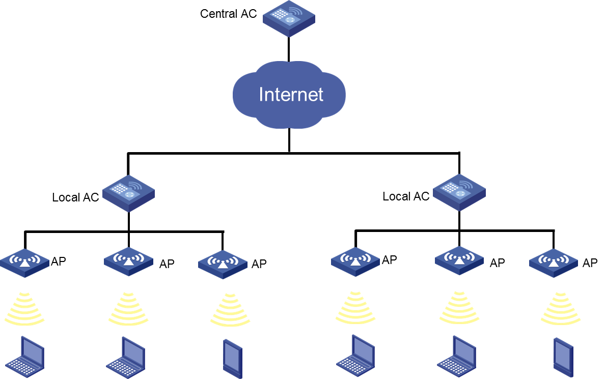
Configuring a central AC
WSM enables you to view information about local ACs associated with a central AC, and add, modify, or delete local ACs.
Viewing the local AC list
1. Click the Service tab.
2. From the navigation tree, select WLAN Manager > Resource Management > ACs.
The AC List page displays all ACs.
3. Click the device label of the target central AC.
The Local AC List displays all local ACs associated with the central AC.
Local AC List
¡ Status—Status of the local AC. Options are Online and Offline.
¡ Serial ID—Serial ID of the local AC.
¡ Local AC Name—Name of the local AC. You can click the name of an online local AC to enter its brief information page.
¡ IP Address—Management IP address of the local AC. This field displays 0.0.0.0 when the local AC is offline.
¡ Model—Model of the local AC.
¡ Modify—Click
the Modify icon ![]() to modify the local AC.
to modify the local AC.
¡ Delete—Click
the Delete icon ![]() to delete the local AC.
to delete the local AC.
Adding a local AC
1. Click the Service tab.
2. From the navigation tree, select WLAN Manager > Resource Management > ACs.
The AC List page displays all ACs.
3. Click the device label of the target central AC.
The Local AC List displays all local ACs associated with the central AC.
4. Click Add.
The Add Local AC page opens.
5. Set the following parameters:
¡ Local AC Name—Enter the local AC name, a string of 1 to 63 characters. The name can contain only letters, digits, and underscores (_).
¡ Serial ID—Enter the serial ID of the local AC, a string of 1 to 64 characters. The serial ID cannot contain question marks (?), apostrophes ('), or spaces.
¡ Model—Select the local AC model.
6. Click OK.
Modifying a local AC
This function enables you to change the serial ID of a local AC.
To modify the serial ID of a local AC:
1. Click the Service tab.
2. From the navigation tree, select WLAN Manager > Resource Management > ACs.
The AC List page displays all ACs.
3. Click the device label of the target central AC.
The Local AC List displays all local ACs associated with the central AC.
4. Click the Modify icon ![]() for the
target local AC.
for the
target local AC.
5. Change the serial ID of the AC.
6. Click OK.
Deleting a local AC
1. Click the Service tab.
2. From the navigation tree, select WLAN Manager > Resource Management > ACs.
The AC List page displays all ACs.
3. Click the device label of the target central AC.
The Local AC List displays all local ACs associated with the central AC.
4. Click the Delete icon ![]() for the
target local AC.
for the
target local AC.
A confirmation dialog box opens.
5. Click OK.
Configuring a local AC
This function enables you to enable the local AC function and specify a central AC for local ACs.
To configure a local AC:
1. Click the Service tab.
2. From the navigation tree, select WLAN Manager > Resource Management > ACs.
The AC List page displays all ACs.
3. Click the device label of the target local AC.
4. Click Configure Local AC Settings in the AC Configuration area.
5. Select Enable Local AC.
6. Select the IP address of a central AC in the menu.
7. Click OK.
Viewing supported local AC models
This function enables you to view local AC models supported by the central AC.
To view supported local AC models:
1. Click the Service tab.
2. From the navigation tree, select WLAN Manager > Resource Management > ACs.
The AC List page displays all ACs.
3. Click the device label of the target central AC.
4. Click View Supported Local AC Models in the AC Configuration area.
Local AC List
¡ Model—Local AC model.
¡ Name—Local AC name.
¡ Vendor—Local AC vendor.
¡ CPU Model/Frequency—CPU models and frequencies supported by the local AC.
¡ Memory Model/Size—Memory models and sizes supported by the local AC.
¡ Flash Model/Size—Flash models and sizes supported by the local AC.
Managing AC groups
WSM uses a primary/secondary mechanism to guarantee high availability. You can add two or more ACs to one AC group and configure one or more ACs to operate in primary state. Other ACs operate in secondary state.
If a primary AC goes down, a secondary AC immediately takes over the role of the primary AC.
ACs in the same AC group back up each other. Every AC in the group works actively and serves as the secondary AC the others. The primary and secondary ACs have the same configuration.
Viewing the AC group list
1. Click the Service tab.
2. From the navigation tree, select WLAN Manager > Configuration Management.
The Configuration Management page opens.
3. Click the Comware-Based tab.
4. In the Network Management area, click AC Group.
The AC Group List page displays all AC groups.
AC Group List
¡ Group Name—Name of the AC group. Click the name of the group to view its details. For more information, see "Viewing the AC group details."
¡ Modify—Click the Modify icon ![]() to change the name of the AC group. For more information, see
"Modifying an AC group."
to change the name of the AC group. For more information, see
"Modifying an AC group."
¡ Delete—Click the Delete icon ![]() to delete the AC group. For more information, see "Deleting an AC group."
to delete the AC group. For more information, see "Deleting an AC group."
5. Click Refresh to view the most recent AC Group List.
If the AC Group List contains enough entries, the following navigational aids are displayed:
· Click the Next Page
icon ![]() to page
forward in the AC Group List.
to page
forward in the AC Group List.
· Click the Last Page
icon ![]() to page
forward to the end of the AC Group List.
to page
forward to the end of the AC Group List.
· Click the Previous Page
icon ![]() to page
backward in the AC Group List.
to page
backward in the AC Group List.
· Click the First Page
icon ![]() to page
backward to the front of the AC Group List.
to page
backward to the front of the AC Group List.
Click 8, 15, 50, 100, or 200 at the upper right of the AC Group List to specify the number of items you want to display on each page.
You can sort the AC Group List by Group Name field. Click the column label to sort the list by the selected field.
Viewing the AC group details
1. Click the Service tab.
2. From the navigation tree, select WLAN Manager > Configuration Management.
The Configuration Management page opens.
3. Click the Comware-Based tab.
4. In the Network Management area, click AC Group.
The AC Group List page opens.
5. Click the name of the AC group to view details.
The AC List displays all ACs in the group.
AC List
¡ Status—Current alarm status of the AC.
¡ Device Label—Device label of the AC. Click the label of the target AC to view its details.
¡ Model—Device model of the AC.
¡ IP Address—IP address of the AC.
¡ Online Fit APs—Number of online fit APs managed by the AC. Click the link showing the number of online fit APs to view the Fit AP List.
¡ Online Clients—Total number of online clients logging in the fit APs of the AC. Click the link showing the number of online clients to view the Client List. For more information about the list, see "Viewing the client list."
6. Click Refresh to view the most recent AC List.
If the AC List contains enough entries, the following navigational aids are displayed:
· Click the Next Page
icon ![]() to page
forward in the AC List.
to page
forward in the AC List.
· Click the Last Page
icon ![]() to page
forward to the end of the AC List.
to page
forward to the end of the AC List.
· Click the Previous Page
icon ![]() to page
backward in the AC List.
to page
backward in the AC List.
· Click the First Page
icon ![]() to page
backward to the front of the AC List.
to page
backward to the front of the AC List.
Click 8, 15, 50, 100, or 200 at the upper right of the AC List to specify the number of items you want to display on each page.
You can sort the AC List by every field. Click the column label to sort the list by the selected field. The column label allows you to toggle between the sort options specific to each field.
Adding an AC group
1. Click the Service tab.
2. From the navigation tree, select WLAN Manager > Configuration Management.
The Configuration Management page opens.
3. Click the Comware-Based tab.
4. In the Network Management area, click AC Group.
The AC Group List displays all AC groups.
5. Click Add.
The Add AC Group page opens.
6. Enter a name for the new AC group to uniquely identify the group in the list.
7. Click OK.
Modifying an AC group
This function enables you to change the name of an AC group.
To modify the name of an AC group:
1. Click the Service tab.
2. From the navigation tree, select WLAN Manager > Configuration Management.
The Configuration Management page opens.
3. Click the Comware-Based tab.
4. In the Network Management area, click AC Group.
The AC Group List page displays all AC groups.
5. Click the Modify
icon ![]() for an
AC group.
for an
AC group.
The Modify AC Group page opens.
6. Enter a new name for the AC group to uniquely identify the group in the list.
7. Click OK.
Deleting an AC group
This function deletes an AC group from WSM, regardless of whether the AC group has any AC. Deleting the AC group removes the ACs from the group, but not from WSM.
To delete an AC group:
1. Click the Service tab.
2. From the navigation tree, select WLAN Manager > Configuration Management.
The Configuration Management page opens.
3. Click the Comware-Based tab.
4. In the Network Management area, click AC Group.
The AC Group List displays all AC groups.
5. Click the Delete
icon ![]() for an
AC group.
for an
AC group.
A confirmation dialog box opens.
6. Click OK.
Configuring the default AC synchronization operation
1. Click the Service tab.
2. From the navigation tree, select WLAN Manager > Configuration Management.
The Configuration Management page opens.
3. Click the Comware-Based tab.
4. In the Network Management area, click AC Group.
The AC Group List displays all AC groups.
5. To synchronize AC configurations by default, select one of the following:
¡ Yes—the configurations are synchronized between primary/secondary ACs by default when the configuration of an AC changes.
¡ No—the configurations are not synchronized between primary/secondary ACs by default when the configuration of an AC changes.
6. Click OK.
Adding ACs to an AC group
You can add the same AC to different AC groups.
To add ACs to an AC group:
1. Click the Service tab.
2. From the navigation tree, select WLAN Manager > Configuration Management.
The Configuration Management page opens.
3. Click the Comware-Based tab.
4. In the Network Management area, click AC Group.
The AC Group List displays all AC groups.
5. Click the name of the target AC group.
The AC List page opens.
6. Click Add AC.
The Select Devices page opens.
7. Specify one or more of the following query criteria:
¡ Device Label—Enter the device label of the AC. WSM supports fuzzy matching for this field.
¡ IP Address—Enter a partial or complete IPv4 address of the AC. WSM supports fuzzy matching for this field.
¡ Model—Select the AC model. Options are Unlimited and all AC models available for WSM.
An empty field or a field that is set to Unlimited does not serve as a query criterion.
8. Click Query.
The AC List displays all ACs matching the query criteria.
9. Select the ACs you want to add to the AC group.
10. Click OK.
The selected ACs are added to the group.
Removing ACs from an AC group
1. Click the Service tab.
2. From the navigation tree, select WLAN Manager > Configuration Management.
The Configuration Management page opens.
3. Click the Comware-Based tab.
4. In the Network Management area, click AC Group.
The AC Group List page opens.
5. Click the name of an AC group to view details.
The AC List page opens.
6. Select the ACs you want to remove from the group.
7. Click Remove AC.
A confirmation dialog box opens.
8. Click OK.
Managing policy templates
An AC issues radio policies and service policies to the managed fit APs. Applying an appropriate policy template to the AC can simplify the procedure because you do not need to configure the same parameters repeatedly on each policy. You can manage the following types of policy templates on the Template Management page:
· Radio policy templates
· Service policy templates
Managing radio policy templates
Applying an appropriate radio policy template to the AC can simplify the radio policy configuration procedure because you only need to change the policy name.
Viewing the radio policy template list
1. Click the Service tab.
2. From the navigation tree, select WLAN Manager > Configuration Management.
The Configuration Management page opens.
3. Click the Comware-Based tab.
4. In the Network Management area, click Template Management.
The Template Management page opens. By default, the Radio Policy Template List appears, showing all radio policy templates.
Radio Policy Template List
¡ Policy Name—Name of the radio policy template.
¡ Beacon Interval—Interval at which a fit AP sends a beacon frame.
¡ DTIM Interval—Number of beacon intervals an AP waits before it sends buffered multicast and broadcast frames.
¡ RTS Threshold—Length of frames for which the RTS method is used.
¡ Fragment Threshold—Maximum length of frames that can be transmitted without fragmentation.
¡ Rx Lifecycle—Interval for an AP to hold a received frame in its buffer memory.
¡ Modify—Click the Modify icon ![]() for the target radio policy template to modify its parameters. For
more information, see "Modifying a radio policy template."
for the target radio policy template to modify its parameters. For
more information, see "Modifying a radio policy template."
¡ Delete—Click the Delete icon ![]() for the target radio policy template to delete the template. For
more information, see "Deleting a radio policy template."
for the target radio policy template to delete the template. For
more information, see "Deleting a radio policy template."
Viewing radio policy template details
1. Click the Service tab.
2. From the navigation tree, select WLAN Manager > Configuration Management.
The Configuration Management page opens.
3. Click the Comware-Based tab.
4. In the Network Management area, click Template Management.
The Template Management page opens. By default, the Radio Policy Template List appears, showing all radio policy templates.
5. Click the name of the target radio policy template.
The Radio Policy Template Details dialog box opens.
Radio Policy Template Details
¡ Policy Name—Name of the radio policy template.
¡ Beacon Interval (TU)—Interval at which a fit AP sends a beacon frame.
¡ DTIM Interval—Number of beacon intervals a fit AP waits before it sends buffered multicast and broadcast frames.
¡ RTS Threshold (bytes)—Length of frames for which the RTS method is used.
¡ Fragment Threshold (bytes)—Maximum length of frames that can be transmitted without fragmentation.
¡ Short Frame Retransmission Threshold—Maximum retransmit times for frames that are not longer than RTS Threshold.
¡ Long Frame Retransmission Threshold—Maximum retransmit times for frames that are longer than RTS Threshold.
¡ Rx Lifecycle (ms)—Interval for a fit AP to hold a received frame in its buffer memory.
¡ Max Clients—Maximum number of clients allowed in the radio policy.
6. Click Close.
Adding a radio policy template
1. Click the Service tab.
2. From the navigation tree, select WLAN Manager > Configuration Management.
The Configuration Management page opens.
3. Click the Comware-Based tab.
4. In the Network Management area, click Template Management.
The Template Management page opens. By default, the Radio Policy Template List appears and displays all radio policy templates.
5. Click Add.
The Add Radio Policy Template page opens.
6. Set the following parameters:
¡ Policy Name—Enter a name for the radio policy template. The policy name must not be longer than 15 characters, and not the same as any existing radio policy name. Only alphanumeric characters and underscores (_) are allowed.
¡ Beacon Interval (TU)—Enter an interval at which a fit AP sends a beacon frame. The value for the interval ranges from 32 to 8191, in TU, and the default value is 100. (1 TU equals 1024 microseconds.)
¡ DTIM Interval—Enter the number of beacon intervals a fit AP waits before it sends buffered multicast and broadcast frames. The value for the DTIM Interval ranges from 1 to 31, and the default value is 1, where 1 equals 100 TU. When the DTIM Interval counts down to 0, the fit AP sends buffered multicast and broadcast frames to wireless clients.
¡ RTS Threshold (bytes)—Enter the length of frames for which the RTS method is used. The value ranges from 0 to 2346, and the default value is 2346. Set a rational value to effectively avoid data sending collisions in a WLAN. If you set a small value, RTS packets are sent frequently, consuming more of the available bandwidth, but the system can recover quickly from interference or collisions.
¡ Fragment Threshold (bytes)—Enter the maximum length of frames that can be transmitted without fragmentation. The value is an even number ranging from 256 to 2346, and the default value is 2346. A frame longer than Fragment Threshold is transmitted in fragments.
¡ Short Frame Retransmission Threshold—Enter the maximum retransmit times for frames that are not longer than RTS Threshold. The value is ranges from 1 to 15, and the default value is 7.
¡ Long Frame Retransmission Threshold—Enter the maximum retransmit times for frames that are longer than RTS Threshold. The value is ranges from 1 to 15, and the default value is 4.
¡ Rx Lifecycle (ms)—Enter the interval for a fit AP to hold a received frame in its buffer memory. The value is in the range of 500 to 250000, and the default value is 2000.
¡ Max Clients—Enter the maximum number of clients allowed in the radio policy. The value is in the range of 1 to 124, and the default value is 64.
7. Click OK.
Modifying a radio policy template
You cannot modify the name of an existing radio policy template.
To modify a radio policy template:
1. Click the Service tab.
2. From the navigation tree, select WLAN Manager > Configuration Management.
The Configuration Management page opens.
3. Click the Comware-Based tab.
4. In the Network Management area, click Template Management.
The Template Management page opens. By default, the Radio Policy Template List appears, displaying all radio policy templates.
5. Click the Modify
icon ![]() for a
radio policy template.
for a
radio policy template.
The Modify Radio Policy Template page opens.
6. Modify the radio policy parameters except the policy name.
For more information about the parameters, see "Adding a radio policy template."
7. Click OK.
Deleting a radio policy template
1. Click the Service tab.
2. From the navigation tree, select WLAN Manager > Configuration Management.
The Configuration Management page opens.
3. Click the Comware-Based tab.
4. In the Network Management area, click Template Management.
The Template Management page opens. By default, the Radio Policy Template List appears, displaying all radio policy templates.
5. Click the Delete
icon ![]() for a
radio policy template.
for a
radio policy template.
A confirmation dialog box opens.
6. Click OK.
Managing service policy templates
Applying an appropriate service policy template to the AC can simplify the service policy configuration procedure because you only need to change the policy ID and interface ID.
Viewing the service policy template list
1. Click the Service tab.
2. From the navigation tree, select WLAN Manager > Configuration Management.
The Configuration Management page opens.
3. Click the Comware-Based tab.
4. In the Network Management area, click Template Management.
The Template Management page opens. There are two types of policy templates:
¡ Radio Policy Template
¡ Service Policy Template
5. Click Service Policy Template.
The Service Policy Template List page opens, displaying all service policy templates.
Service Policy Template List
¡ SSID—SSID of the service policy template.
¡ Encryption Mode—Encryption mode for the service policy template. Options are:
- Clear—Clients can access the wireless network without any passwords.
- Crypto—Clients must enter the correct password to access the wireless network.
¡ Hide SSID—Indicates whether to provide the SSID in beacon frames sent by the fit AP. If this parameter is selected, clients cannot obtain the SSID from the beacon frames, and must configure the SSID before accessing the wireless network. If this parameter is not selected, clients can obtain the SSID from the beacon frames to access the wireless network.
¡ Authentication Mode—Authentication mode of the service policy template. Options are:
- Open System—Allows all clients requesting for authentication to directly pass authentication.
- Shared Key—Requires clients to use the same shared key as that configured on the device. Select Shared Key only when you select WEP40, WEP104, or WEP128 as the cipher suite.
- All—Allows clients to use either the Open System mode or the Shared Key mode as needed.
¡ Modify—Click the Modify icon ![]() for the target service policy template to modify its parameters. For
more information, see "Modifying a service policy template."
for the target service policy template to modify its parameters. For
more information, see "Modifying a service policy template."
¡ Delete—Click the Delete icon ![]() for the target service policy template to delete the template. For
more information, see "Deleting a service policy template."
for the target service policy template to delete the template. For
more information, see "Deleting a service policy template."
Viewing service policy template details
1. Click the Service tab.
2. From the navigation tree, select WLAN Manager > Configuration Management.
The Configuration Management page opens.
3. Click the Comware-Based tab.
4. In the Network Management area, click Template Management.
The Template Management page opens. There are two types of policy templates:
¡ Radio Policy Template
¡ Service Policy Template
5. Click Service Policy Template.
The Service Policy Template List page opens, displaying all service policy templates.
6. Click the SSID of the target service policy template to view its details, including the Basic Information and the Security Information. The Security Information is not available for the service policy template with the Encryption Mode set to Clear.
Basic Information
¡ SSID—SSID of the service policy template.
¡ Encryption Mode—Encryption mode for the service policy template. Options are:
- Clear—Clients can access the wireless network without any passwords.
- Crypto—Clients must enter the correct password to access the wireless network.
¡ Hide SSID—Indicates whether to provide the SSID in beacon frames sent by the fit AP. If this parameter is selected, clients cannot obtain the SSID from the beacon frames and must configure the SSID before accessing the wireless network. If this parameter is not selected, clients can obtain the SSID from the beacon frames to access the wireless network.
¡ Authentication Mode—Authentication mode of the service policy template. Options are:
- Open System—Allows all clients requesting for authentication to directly pass authentication.
- Shared Key—Requires clients to use the same shared key as that configured on the device. Select Shared Key only when you select WEP40, WEP104, or WEP128 as the cipher suite.
- All—Allows clients to use either the Open System mode or the Shared Key mode as needed.
¡ Max Clients—Maximum number of clients allowed in the service policy.
¡ Layer2 Isolation—Enable or disable Layer 2 isolation. Configure this parameter in combination with the user-isolation vlan command executed on the AC. With the function enabled, clients in the permitted MAC address list can communicate with other clients in the same VLAN. For example, if you execute the user-isolation vlan 1 permit-mac 0000-1111-2222 command on the AC and enable Layer 2 isolation, client 0000-1111-2222 can visit other clients in VLAN 1, but other clients cannot visit each other.
|
|
NOTE: For clients to access the network after you enable Layer 2 isolation, first add the MAC address of the gateway to the permitted MAC address list. |
Security Information
¡ Security IE—Security IE used in the beacon frames and probe responses sent by the fit AP. Options are None (default), RSN, WPA, and All. None indicates no security IE is configured. All indicates both RSN and WPA are configured. For more information about RSN and WPA, see the related device manual.
¡ Cipher Suite—Cipher suite used in data frame encryption and decryption. Options are:
- TKIP
- CCMP
- WEP40
- WEP104
- WEP128
¡ Key Index—Authentication key index for clients.
¡ Key—Authentication key for clients.
7. Click Close.
Adding a service policy template
1. Click the Service tab.
2. From the navigation tree, select WLAN Manager > Configuration Management.
The Configuration Management page opens.
3. Click the Comware-Based tab.
4. In the Network Management area, click Template Management.
The Template Management page opens. There are two types of policy templates: Radio Policy Template and Service Policy Template.
5. Click Service Policy Template.
The Service Policy Template List page opens, displaying all service policy templates.
6. Click Add.
The page for adding service policy templates opens.
7. Set the following parameters:
¡ SSID—Enter the SSID of the service policy template, a string of 1 to 32 characters. For valid characters in the SSID string, see "Adding a WLAN."
¡ Encryption Mode—Select an encryption mode for the service policy template. Options are:
- Clear—The Security Information area is not available for the service policy template, and the clients can access the wireless network without any passwords.
- Crypto—You must configure the parameters in the Security Information area for the template, and the clients must enter the correct password to access the wireless network.
¡ Hide SSID—Select this option to hide the SSID in beacon frames sent by the fit AP. When this parameter is selected, clients cannot obtain the SSID from the beacon frames, and they must configure the SSID before accessing the wireless network. If this parameter is not selected, clients can obtain the SSID from the beacon frames to access the wireless network.
¡ Authentication Mode—Select the authentication mode of the service policy from the list. Options are:
- Open System—Allows all clients requesting for authentication to directly pass authentication.
- Shared Key—Requires clients to use the same shared key as that configured on the device. Select Shared Key only when you select WEP40, WEP104, or WEP128 as the cipher suite.
- All—Allows clients to use either the Open System mode or the Shared Key mode as needed.
When the encryption mode is Clear, the authentication mode can only be Open System. When the encryption mode is Crypto, the authentication mode options are Open System, Shared Key, and All.
¡ Layer2 Isolation—Enable or disable Layer 2 isolation. Configure this parameter in combination with the user-isolation vlan command executed on the AC. With the function enabled, clients in the permitted MAC address list can communicate with other clients in the same VLAN. For example, if you execute the user-isolation vlan 1 permit-mac 0000-1111-2222 command on the AC and enable Layer 2 isolation, client 0000-1111-2222 can visit other clients in VLAN 1, but other clients cannot visit each other.
|
|
NOTE: For clients to access the network after you enable Layer 2 isolation, first add the MAC address of the gateway to the permitted MAC address list. |
¡ Max Clients—Maximum number of clients allowed in the service policy.
8. If Crypto is selected as the Encryption Mode, set the following security parameters, as needed:
¡ Security IE—Select the security IE used in the beacon frames and probe responses sent by the fit AP. Options are
¡ None—No security IE is configured.
¡ RSN—A robust security network is a security network that only allows the creation of robust security network associations to provide greater protection than WEP and WPA.
¡ WPA—WPA is superior to WEP, which operates in either WPA-PSK (or Personal) mode or WPA-802.1X (or Enterprise) mode. In Personal mode, a pre-shared key or pass-phrase is used for authentication. In Enterprise mode, 802.1X and RADIUS servers and the EAP are used for authentication.
¡ All—Both RSN and WPA are configured.
For more information about RSN and WPA, see the related device manual.
¡ Cipher Suite—Select the cipher suite used for data frame encryption and decryption. Options are TKIP, CCMP, WEP40, WEP104, and WEP128. You can set the key index and key only when you select WEP40, WEP104, or WEP128. You cannot select WEP40, WEP104, and WEP128 at the same time.
- WEP—Includes WEP40, WEP104, and WEP128. They are all static WEP encryption mechanisms. A WEP40 key is 40 bits, a WEP104 key is 104 bits, and a WEP128 key is 128 bits. WEP uses RC4 encryption, and requires that all clients accessing the wireless network use the same key.
- TKIP—Temporal Key Integrity Protocol uses the RC4 algorithm as WEP does, but provides more secure protection for WLAN. TKIP enhances the security of pre-802.11i hardware.
- CCMP—Counter mode with CBC-MAC Protocol is a Counter-Mode/CBC-MAC mechanism based on AES to provide high security.
¡ Key Index—Enter the authentication key index for clients.
¡ Key—Enter the authentication key for clients. For WEP40, the key is a string of 5 alphanumeric characters. For WEP104, the key is a string of 13 alphanumeric characters. For WEP128, the key is a string of 16 alphanumeric characters.
9. Click OK.
Modifying a service policy template
This function cannot modify the SSID of an existing service policy template.
To modify a service policy template:
1. Click the Service tab.
2. From the navigation tree, select WLAN Manager > Configuration Management.
The Configuration Management page opens.
3. Click the Comware-Based tab.
4. In the Network Management area, click Template Management.
The Template Management page opens. There are two types of policy templates:
¡ Radio Policy Template
¡ Service Policy Template
5. Click Service Policy Template.
The Service Policy Template List page opens, displaying all service policy templates.
6. Click the Modify
icon ![]() for a
service policy template.
for a
service policy template.
The Modify Service Policy Template page opens.
7. Modify the service policy template parameters.
For more information about these parameters, see "Adding a service policy template."
8. Click OK.
Deleting a service policy template
1. Click the Service tab.
2. From the navigation tree, select WLAN Manager > Configuration Management.
The Configuration Management page opens.
3. Click the Comware-Based tab.
4. In the Network Management area, click Template Management.
The Template Management page opens. There are two types of policy templates:
¡ Radio Policy Template
¡ Service Policy Template
5. Click Service Policy Template.
The Service Policy Template List page opens, displaying all service policy templates.
6. Click the Delete
icon ![]() for a
service policy template.
for a
service policy template.
A confirmation dialog box opens.
7. Click OK.
General management functions
WSM offers the following general management functions for Comware-based access controllers:
· Viewing Topology
· Ping
· Traceroute
· Open Web Manager
· Telnet
· SSH
For more information about these functions, see "Managing MSM series access controllers"
Managing Cisco access controllers
WSM enables you to manage Cisco ACs, including managing groups and WLANs, and configuring radio parameters.
Before managing a Cisco AC, add the AC to the IMC platform, configure SNMP parameters, and synchronize the AC to IMC. After synchronization, the AC is automatically added to WSM and displayed on the AC list.
Viewing the AC list
1. Click the Service tab.
2. From the navigation tree, select WLAN Manager > Resource Management > ACs.
The AC List displays all ACs that have been added to IMC.
The parameters for a Cisco AC are the same as the parameters for an HP MSM series/HP Comware-based AC. For more information, see "Viewing the AC list."
The Operation menu content for a Cisco AC is different from that for an HP MSM series/HP Comware-based AC.
Synchronizing ACs
Synchronizing a Cisco AC is the same as synchronizing an HP MSM series/HP Comware-based AC. For more information, see "Synchronizing ACs."
Querying ACs
WSM provides basic query and advanced query. Basic query criteria include several key parameters for quick searches. Advanced query offers various query criteria for precise matching.
To query ACs:
1. Click the Service tab.
2. From the navigation tree, select WLAN Manager > Resource Management > ACs.
The AC List displays all ACs.
3. Perform a basic query:
a. Enter the device label (case-insensitive) or IP address of the AC. WSM supports fuzzy matching for this field. For example, if you enter 19, all ACs with device labels or IP addresses containing 19 are queried.
b. Click the Query icon
![]() . The Device List displays all ACs matching the query criteria.
. The Device List displays all ACs matching the query criteria.
c. Clear the Query
field, and then click the Query icon ![]() to display all
ACs.
to display all
ACs.
4. Perform an advanced query:
a. Enter or select one or more of the following query criteria in the Query area:
- Device Label—Enter a partial or complete device label (case-insensitive) of the AC.
- IP Address—Enter a partial or complete IPv4 address of the AC.
- Device Status—Select a device state for the AC. Options are: Unlimited, Critical, Major, Minor, Warning, Normal, Unmanaged, and Unknown.
- Connectivity Status—Select a connectivity state for the AC. Options are Unlimited, Reachable, and Unreachable.
- Vendor—Select the vendor of the AC. Options are Unlimited, H3C, HP, Cisco, and Aruba.
b. Click Query. The Device List displays all ACs matching the query criteria.
c. Click Reset to clear the query criteria and display all ACs.
Viewing brief information about an AC
1. Click the Service tab.
2. From the navigation tree, select WLAN Manager > Resource Management > ACs.
The AC List page displays all ACs.
3. Click the device label of an AC.
The page displays brief information about the AC.
Device Information
¡ Device Label—Device label of the AC.
¡ Device Status—Alarm status of the AC.
¡ IP Address—IPv4 address of the AC.
¡ Device Model—Device model of the AC.
The Wireless Service Information area provides global parameter information for the AC. For more information, see "Viewing detailed information about an AC."
The Client Count graph and the AP Bandwidth graph provide online client and AP bandwidth trends. For more information, see "Client Count" and "AP Bandwidth."
The Wireless Service Alarm area provides information about the alarms that the AC generates. For more information, see "Viewing wireless service alarms."
Viewing detailed information about an AC
1. Click the Service tab.
2. From the navigation tree, select WLAN Manager > Resource Management > ACs.
3. Click the device label of an AC.
4. In the top right corner of the brief AC information page, click More Detailed.
The AC details page opens.
This section only describes wireless service information about the AC. For other information displayed on the AC details page, see H3C IMC v7.3 Enterprise and Standard Platform Administrator Guide.
5. Click the Wireless Service Information tab on the lower part of the page.
Global Parameter Information
¡ Max APs—Maximum number of fit APs that can be managed by the AC.
¡ Online Fit APs—Number of online fit APs managed by the AC.
¡ Online Clients—Number of clients that have been associated with the fit APs managed by the AC.
6. Click the Global Configuration link to configure global parameters for the AC. For more information, see "Configuring global parameters for an AC."
Configuring global parameters for an AC
The global parameters of an AC take effect on all fit APs managed by the AC.
The AC automatically adjusts the transmit power level for radios according to TPC configuration to avoid interference between radios caused by too-large power. You can also perform one-time TPC for all radios.
The global parameters of radio 1 take effect on 802.11b/g/n radios. The global parameters of radio 2 take effect on 802.11a/n radios. For example, if you disable the network status of radio 1, all 802.11b/g/n radios are unavailable.
To configure global parameters for an AC:
1. Click the Service tab.
2. From the navigation tree, select WLAN Manager > Resource Management > ACs.
3. Click the device label of an AC.
4. Click the Wireless Service Information tab on the lower part of the page.
5. Click Global Configuration in the Wireless Service Information area.
6. Configure global parameters for radio 1:
Configure radio 2 in the same way radio 1 is configured.
Options are: Automatic, On Demand, and Fixed.
¡ Automatic—If you select this option, the AC automatically adjusts the transmit power level of all radios. Adjusting radio transmit power can reduce interference and enhance wireless network performance.
¡ On Demand—If you select this option, you need to click Invoke Power Update Once to enable the AC to adjust the transmit power level of the radio.
¡ Fixed—Set the transmit power level of the radio to a fixed value, in the range of 1 to 5. For more information, see Table 9, which is a reference only.
|
Power level |
Value |
|
1 |
Maximum power allowed by the country code of the radio |
|
2 |
50% × maximum power |
|
3 |
25% × maximum power |
|
4 |
6.25-12.5% × maximum power |
|
5 |
0.195-6.25% × maximum power |
TPC takes effect only on radios whose transmit power levels are globally assigned.
¡ Radio 1 Network Status—Enable or disable the network of Radio 1. If you do not enable the network of Radio 1, 802.11b/g/n radios are not available. The network status of a radio determines the operation status of the radio.
|
|
NOTE: · A radio has two status: admin status and operation status. A radio can operate only when its admin status is Enable and operation status is Up. · The operation status of a radio is determined by the admin status of the AP and the network status of the radio. The operation status of a radio is up only when both of them are Enable. |
¡ Maximum Power Level Assignment (–10 to 30dBm)—The maximum power level that an AC can assign to the radio, in the range of –10 to 30 dBm. The power level after auto-TPC will not exceed the maximum power level. For example, if you set the maximum power level to 20 dBm, the power level that the AC assigns to the radio after auto-TPC will not exceed 20 dBm.
¡ Minimum Power Level Assignment (–10 to 30dBm)—The minimum power level that an AC can assign to the radio, in the range of –10 to 30 dBm. The power level after auto-TPC will not be smaller than the minimum power level. For example, if you set the minimum power level to –5 dBm, the power level that the AC assigns to the radio after auto-TPC will not be smaller than –5 dBm.
The minimum power level must be smaller than the maximum power level.
¡ Power Threshold (–80 to –50 dBm)—Power adjustment threshold. A greater threshold indicates a high transmit power of APs.
7. Click OK.
Viewing fit APs managed by an AC
1. Click the Service tab.
2. From the navigation tree, select WLAN Manager > Resource Management > ACs.
3. Click the number link in the Total APs column of an AC.
The Fit APs page displays all online fit APs managed by the AC. For more information about fit AP list details, see "Viewing the fit AP list."
On the Fit AP List, click the name link of a fit AP to view its details. For more information, see "Viewing detailed information about a fit AP."
Viewing online fit APs managed by an AC
1. Click the Service tab.
2. From the navigation tree, select WLAN Manager > Resource Management > ACs.
3. Click the number link in the Online APs column of an AC.
The Fit APs page displays all online fit APs managed by the AC. For more information about fit AP list details, see "Viewing the online fit APs managed by an AC."
On the Fit AP List, click the name link of a fit AP to view its details. For more information, see "Viewing detailed information about a fit AP."
Viewing the online clients of an AC
1. Click the Service tab.
2. From the navigation tree, select WLAN Manager > Resource Management > ACs.
3. Click the number link in the Clients column of an AC.
The Client List page displays all online clients that are associated with the fit APs managed by the AC. For more information about the Client List, see "Viewing the online clients of an AC."
On the Online Client List, click the MAC address link of a client to view its details. For more information, see "Viewing detailed information about a client."
Managing groups of an AC
You can add WLANs and APs to a group. An AP provides wireless services through the WLAN in the group to which it belongs. A WLAN and an AP are automatically added to the default group when they are created. A WLAN can be added to multiple groups, but an AP can only be added to one group.
You can add WLANs and APs to different groups based on area or floor in a complicated wireless network. For example, for a two-floor building, you can create two different groups for the two floors, and add all APs deployed on each floor and the corresponding WLAN to group 1 and group 2, respectively. After the configuration, APs on different floors provide wireless services through their own WLAN.
Viewing information about groups created on an AC
1. Click the Service tab.
2. From the navigation tree, select WLAN Manager > Resource Management > ACs.
3. Click the Operation
icon ![]() for an
AC.
for an
AC.
4. From the menu, select Group Configuration.
The Group list displays all groups created on the AC.
¡ Name—Name of the group.
¡ APs in Group—Number of APs in the group.
¡ Bind to WLAN—Click the Bind to WLAN icon ![]() to bind the group
to a WLAN. For more information, see "Adding/Removing a WLAN to/from a group."
to bind the group
to a WLAN. For more information, see "Adding/Removing a WLAN to/from a group."
¡ Modify—Click the Modify ![]() icon for the group to modify its parameters. For more information,
see "Modifying a group."
icon for the group to modify its parameters. For more information,
see "Modifying a group."
¡ Delete—Click the Delete icon ![]() to delete the group.
to delete the group.
5. Select 8, 15, 50, 100, or 200 at the bottom of the group list to configure how many items per page you want to display.
If the Group list contains enough entries, use the following aids to navigate the list:
¡ Click
the Next Page icon ![]() to page forward in the Group list.
to page forward in the Group list.
¡ Click
the Last Page icon ![]() to page forward to the end of the Group
list.
to page forward to the end of the Group
list.
¡ Click
the Previous Page icon ![]() to page backward in the Group list.
to page backward in the Group list.
¡ Click
the First Page icon ![]() to page backward to the front of the Group
list.
to page backward to the front of the Group
list.
¡ Click a page number to display the page in the Group list.
6. Click the Sort
icon ![]() on the Group or AP Count column
label to sort the Group list.
on the Group or AP Count column
label to sort the Group list.
When the Descending icon ![]() or Ascending icon
or Ascending icon ![]() appears on a blue
column label, the Group list is sorted by that column.
appears on a blue
column label, the Group list is sorted by that column.
7. Click Refresh to view the most recent information.
To perform related operations, click Related Operations, and select WLAN Configuration or Radio Batch Configuration from the menu. For more information, see "Managing WLANs of an AC" and "Configuring radio parameters for an AC."
Adding a group
1. Click the Service tab.
2. From the navigation tree, select WLAN Manager > Resource Management > ACs.
3. Click the Operation
icon ![]() for an
AC.
for an
AC.
4. From the menu, select Group Configuration.
5. Click Add.
6. Set the following parameters:
¡ Name—Enter a name for the group in the range of 1 to 63 characters. The name string can include only case-sensitive letters, numbers, and special characters (see Table 10).
¡ Description—Enter a description for the group.
|
Character name |
Symbol |
Character name |
Symbol |
|
Apostrophe |
` |
Asterisk |
* |
|
At sign |
@ |
Caret |
^ |
|
Colon |
: |
Comma |
, |
|
Dollar sign |
$ |
Dot |
. |
|
Equal sign |
= |
Hyphen |
- |
|
Left brace |
{ |
Left bracket |
[ |
|
Left parenthesis |
( |
Right brace |
} |
|
Right bracket |
] |
Right parenthesis |
) |
|
Semi-colon |
; |
Tilde |
~ |
|
Underscore |
_ |
Vertical bar |
| |
7. Click OK.
Modifying a group
The name of a group cannot be modified.
To modify a group:
1. Click the Service tab.
2. From the navigation tree, select WLAN Manager > Resource Management > ACs.
3. Click the Operation
icon ![]() for an
AC.
for an
AC.
4. From the menu, select Group Configuration.
5. Click the Modify
icon ![]() for the
target group.
for the
target group.
6. Enter a description for the group.
7. Click OK.
Deleting a group
The default group cannot be deleted. APs in a group are automatically added to the default group when the group is deleted.
To delete a group:
1. Click the Service tab.
2. From the navigation tree, select WLAN Manager > Resource Management > ACs.
3. Click the Operation
icon ![]() for an
AC.
for an
AC.
4. From the menu, select Group Configuration.
5. Click the Delete
icon ![]() for the
target group.
for the
target group.
6. Click OK in the confirmation dialog box that opens.
Adding/Removing a WLAN to/from a group
A WLAN is automatically added to the default group after being created, and cannot be removed from the default group.
A WLAN can be added to multiple groups.
To add/remove a WLAN to/from a group:
1. Click the Service tab.
2. From the navigation tree, select WLAN Manager > Resource Management > ACs.
3. Click the Operation
icon ![]() for an
AC.
for an
AC.
4. From the menu, select Group Configuration.
5. Click the Bind to WLAN
icon ![]() for the
target group.
for the
target group.
6. Select a WLAN from the WLAN List:
WLAN List
¡ Binding Status—If this option is selected, the WLAN is already in the group. If this option is not selected, the WLAN is not in the group. If you clear a WLAN, the WLAN is removed from the group.
¡ SSID—Enter the SSID of the WLAN.
7. Click OK.
The Result List page opens, showing the operation results.
Result List
¡ Group Name—Name of the group.
¡ SSID—SSID of the WLAN.
¡ AC—Label of the AC to which the group belongs.
¡ Result—Operation results.
8. Click Back to go back to the Group Configuration page.
Managing APs in a group
An AP is automatically added to the default group when it is associated with an AC.
An AP can only be added to one group at the same time.
Viewing the AP list in the group
1. Click the Service tab.
2. From the navigation tree, select WLAN Manager > Resource Management > ACs.
3. Click the Operation
icon ![]() for an
AC.
for an
AC.
4. From the menu, select Group Configuration.
5. Click the name link of a group.
The AP List displays all APs in the group.
AP List
¡ Online Status—Online status of the AP. Options are Online and Offline.
¡ AP Label—Label of the AP.
¡ SN—Serial number of the AP.
¡ IP Address—IP address of the AP.
¡ MAC Address—MAC address of the AP.
¡ Model—Model of the AP.
6. Select 8, 15, 50, 100, or 200 at the bottom of the AP List to configure how many items per page you want to display.
If the AP List contains enough entries, use the following aids to navigate the list:
¡ Click
the Next Page icon ![]() to page forward in the AP List.
to page forward in the AP List.
¡ Click
the Last Page icon ![]() to page forward to the end of the AP List.
to page forward to the end of the AP List.
¡ Click
the Previous Page icon ![]() to page backward in the AP List.
to page backward in the AP List.
¡ Click
the First Page icon ![]() to page backward to the front of the AP
List.
to page backward to the front of the AP
List.
¡ Click a page number to display the page in the AP List.
7. Click the Sort
icon ![]() on any
column label to sort the AP List.
on any
column label to sort the AP List.
When the Descending icon ![]() or Ascending
or Ascending ![]() icon appears on a
blue column label, the AP List is sorted by that column.
icon appears on a
blue column label, the AP List is sorted by that column.
8. Click Refresh to refresh the page.
9. Click Back to return to the Group Configuration page.
Querying APs
WSM provides basic query and advanced query. Basic query criteria include several key parameters for quick searches. Advanced query offers various query criteria for precise matching.
To perform a basic query:
1. Click the Service tab.
2. From the navigation tree, select WLAN Manager > Resource Management > ACs.
3. Click the Operation
icon ![]() for an
AC.
for an
AC.
4. From the menu, select Group Configuration.
5. Click the name of a group.
6. Enter a partial or complete AP label in the query field next to the AP List.
7. Click the Query
icon ![]() .
.
The APs matching the query criteria are displayed in the list.
8. Empty the Query
field, and click the Query icon ![]() .
.
The AP List displays all APs in the group.
To perform an advanced query:
1. Click the Service tab.
2. From the navigation tree, select WLAN Manager > Resource Management > ACs.
3. Click the Operation
icon ![]() for an AC.
for an AC.
4. From the menu, select Group Configuration.
5. Click the Expand
icon ![]() next to the Query field.
next to the Query field.
6. Set the query criteria:
¡ Device Label—Enter a partial or complete device label (case-insensitive) of the AP.
¡ AP Name—Enter the name of the AP.
¡ Serial Number—Enter a partial or complete serial number (case-insensitive) of the AP.
¡ IP Address—Enter a partial or complete IP address of the AP.
¡ Online Status—Select an online status of the AP. Options are: Unlimited, Online, and Offline.
7. Click Query. The APs matching the query criteria are displayed in the list.
8. Click Reset to clear the query criteria and display all ACs.
Adding an AP to a group
1. Click the Service tab.
2. From the navigation tree, select WLAN Manager > Resource Management > ACs.
3. Click the Operation
icon ![]() for an
AC.
for an
AC.
4. From the menu, select Group Configuration.
5. Click the name of a group.
6. Click Add to Group.
The Select Device window opens and displays all APs not in the group.
7. To query APs:
a. Set the query criteria:
- AP Label—Enter a partial or complete device label (case-insensitive) of the AP.
- Serial Number—Enter a partial or complete serial number (case-insensitive) of the AP.
- IP Address—Enter a partial or complete IP address of the AP.
- Online Status—Select the online status of the AP. Options are: Unlimited, Online, and Offline.
- Group—Select another group.
- Location—Enter or select a location view. All APs in the location views are not in the group are queried.
b. Click Query. The APs matching the query criteria are displayed on the list.
c. Click Reset to clear the query criteria and display all APs.
8. Select one or multiple APs from the list.
9. Click OK.
Removing an AP from a group
Removing an AP from a group does not disassociate the AP from an AC. APs removed from a non-default group are automatically added to the default group.
APs in the default group cannot be removed.
To remove an AP from a group:
1. Click the Service tab.
2. From the navigation tree, select WLAN Manager > Resource Management > ACs.
3. Click the Operation
icon ![]() for an
AC.
for an
AC.
4. From the menu, select Group Configuration.
5. Click the name of a group.
6. Select one or multiple APs from the list.
7. Click Delete from this group.
8. Click Refresh to refresh the page.
Moving an AP to another group
An AP uses the WLAN in the new group to provide wireless services after it is moved to another group.
To move an AP to another group:
1. Click the Service tab.
2. From the navigation tree, select WLAN Manager > Resource Management > ACs.
3. Click the Operation
icon ![]() for an
AC.
for an
AC.
4. From the menu, select Group Configuration.
5. Click the name of a group.
6. Select one or multiple APs from the list.
7. Click Change Group.
8. Select a group from the Name list. Options do not include the current group.
9. Click OK.
Managing WLANs of an AC
From the WLAN Manager, you can view the WLAN list, add, modify, and delete a WLAN, and bind a WLAN to groups.
Viewing the WLAN list
1. Click the Service tab.
2. From the navigation tree, select WLAN Manager > Resource Management > ACs.
3. Click the Operation
icon ![]() for an
AC.
for an
AC.
4. From the menu, select WLAN Configuration.
The WLAN List displays all WLANs created on the AC.
WLAN List
¡ WLAN ID—ID of the WLAN, with a maximum value of 16. Click the ID link to view detailed information about the WLAN.
¡ Profile Name—Profile name of the WLAN.
¡ SSID—SSID of the WLAN.
¡ Admin Status—Administrative state for the WLAN. Options include Disable and Enable. If a WLAN is in Disable state, the AP cannot use it to provide wireless services.
¡ Encryption—Security policies of the WLAN. A security policy includes an authentication method and a data encryption method. Options are: None, WPA+WPA2, 802.1X, Static WEP, Static WEP+802.1X, and CKIP.
¡ Operation—Operation that can be performed on the WLAN. Options are: Add, Delete, and Bind to Group. For more information, see the corresponding chapter of each operation.
5. Select 8, 15, 50, 100, or 200 at the bottom of the WLAN List to specify the number of items you want to display on each page.
If the WLAN List contains enough entries, use the following aids to navigate the list:
¡ Click
the Next Page icon ![]() to page forward in the WLAN List.
to page forward in the WLAN List.
¡ Click
the Last Page icon ![]() to page forward to the end of the WLAN List.
to page forward to the end of the WLAN List.
¡ Click
the Previous Page icon ![]() to page backward in the WLAN List.
to page backward in the WLAN List.
¡ Click
the First Page icon ![]() to page backward to the front of the WLAN List.
to page backward to the front of the WLAN List.
6. Click Refresh to view the most recent information.
To perform related operations, click Related Operations, and select Group Configuration or Radio Batch Configuration from the menu. For more information, see "Managing groups of an AC" and "Configuring radio parameters for an AC."
Viewing detailed information about a WLAN
1. Click the Service tab.
2. From the navigation tree, select WLAN Manager > Resource Management > ACs.
3. Click the Operation
icon ![]() for an
AC.
for an
AC.
4. From the menu, select WLAN Configuration.
The WLAN List displays all WLANs created on the AC.
5. Click WLAN ID for a WLAN.
Basic Information
¡ Profile Name—Profile name of the WLAN.
¡ SSID—SSID of the WLAN.
¡ Admin Status—Admin status of the WLAN: Disable and Enable.
¡ Broadcast SSID—Enable APs to broadcast their SSIDs or disable APs from broadcasting their SSIDs. Options are Enable and Disable. Enable indicates the APs bound with the WLAN will broadcast their SSIDs so that they can be discovered by clients. Disable indicates the APs do not support SSID broadcasting.
Security Information
¡ Encryption—Security policy of the WLAN. For more information, see Table 11.
|
Security policy |
Description |
|
None |
Open system authentication. |
|
WPA+WPA2 |
Select at least one policy. · WPA Policy. · WPA Encryption—Options are AES and TKIP. · WPA2 Policy. · WPA2 Encryption—Options are AES and TKIP. · Auth Key Mgmt—Enter a key authentication management method. Options are 802.1X, CCKM, PSK, and 802.1X+CCKM. If you select PSK as the authentication key management method, set the PSK: · PSK Format—Options are HEX and ASCII. · PSK—If the PSK format is HEX, enter a hexadecimal number of 64 bits. If the PSK format is ASCII, enter a string of 8 to 63 characters. |
|
802.1X |
802.11 Data Encryption: · Type—Data encryption mode. Only WEP is supported. · Key Size—Select a shared key size. Options are 40bits and 104bits. Besides the above parameters, log in to the AC to configure AAA and select a RADIUS server for the WLAN. For more information, see the configuration guide of the AC. |
|
Static WEP |
802.11 data encryption: · Type—Enter the data encryption mode. Only WEP is supported. · Key Index—Select a key index in the range of 1 to 4. For clients to access the WLAN, ensure that the key index set on the client is the same as the key index set for the WLAN. · Key Size—Select a key size. Options are 40bits and 104bits. · Key Format—Select a key format, HEX or ASCII. · Encryption Key—Enter an encryption key. · Allow Shared Key Authentication—Whether to enable shared key authentication. |
|
Static WEP+802.1X |
802.11 data encryption: · Type—Enter the data encryption mode. Only WEP is supported. · Key Index—Enter a key index in the range of 1 to 4. For clients to access the WLAN, ensure that the key index set on the client is the same as the key index set for the WLAN. · Key Size—Key size. Options are 40bits and 104bits. · Key Format—Key format, HEX or ASCII. · Encryption Key—Enter an encryption key. · Allow Shared Key Authentication—Enable or disable shared key authentication. 802.11 data encryption: · Type—Enter the data encryption mode. Only WEP is supported. · Key Size—Select a key size. Options are 40bits and 104bits. Besides the above parameters, log in to the AC to configure AAA and select a RADIUS server for the WLAN. For more information, see the configuration guide of the AC. |
|
CKIP |
802.11 data encryption: · Key Size—Select a key size. Options are 40bits and 104bits. · Key Index—Key index in the range of 1 to 4. For clients to access the WLAN, ensure that the key index set on the client is the same as the key index set for the WLAN. · Key Format—Key format, HEX or ASCII. · Encryption Key—Encryption key. · MMH Mode—Enable or disable the Multi-Modular Hash (MMH) mode. · Key Permutation—Whether to enable key permutation. |
Adding a WLAN
If you select 802.1X or Static WEP+802.1X as the security policy, you need to log in to the AC to configure AAA, and select the RADIUS server. For more information, see the configuration guide of the AC.
To add a WLAN:
1. Click the Service tab.
2. From the navigation tree, select WLAN Manager > Resource Management > ACs.
3. Click the Operation
icon ![]() for an
AC.
for an
AC.
4. From the menu, select WLAN Configuration.
The WLAN List displays all WLANs created on the AC.
5. Click Add.
6. Configure the basic information:
¡ Profile Name—Enter a profile name, which is a string of 1 to 32 characters.
¡ SSID—Enter the SSID of the WLAN, which is a string of 1 to 32 characters.
¡ Admin Status—Enable or disable the WLAN. If you select Enable, a WLAN is enabled immediately after it is created. The APs in the default group use this WLAN to provide wireless services because the WLAN is automatically added to the default group.
¡ Broadcast SSID—Enable APs to broadcast their SSIDs or disable APs from broadcasting their SSIDs. Options are Enable and Disable. Enable indicates the APs bound with the WLAN will broadcast their SSIDs so that they can be discovered by clients. Disable indicates the APs do not support SSID broadcasting.
7. Configure security information. For more information, see Table 11.
8. Click OK.
Modifying a WLAN
Modifying a WLAN that is in Enable state makes the WLAN unavailable for a short time, and all clients connected to the WLAN are disconnected.
To modify a WLAN:
1. Click the Service tab.
2. From the navigation tree, select WLAN Manager > Resource Management > ACs.
3. Click the Operation
icon ![]() for an AC.
for an AC.
4. From the menu, select WLAN Configuration.
The WLAN List displays all WLANs created on the AC.
5. Click the Operation
icon ![]() for a
WLAN and select Modify from the menu.
for a
WLAN and select Modify from the menu.
The Profile Name and SSID cannot be modified. For information about how to configure other parameters, see "Adding a WLAN."
6. Click OK.
Binding a WLAN to groups
A WLAN is added to the default group after being created. You cannot remove it from the default group, but you can add it to another group by binding the WLAN to the group.
After a WLAN whose admin status is Enable is added to a group, the APs use the WLAN to provide wireless services.
To bind a WLAN to groups:
1. Click the Service tab.
2. From the navigation tree, select WLAN Manager > Resource Management > ACs.
3. Click the Operation
icon ![]() for an
AC and select WLAN Configuration from the menu.
for an
AC and select WLAN Configuration from the menu.
The WLAN List displays all WLANs created on the AC.
4. Click the Operation
icon ![]() for the WLAN
of the target group and select Group Bindings from the menu.
for the WLAN
of the target group and select Group Bindings from the menu.
The Group List displays all groups created on the AC.
Group List
¡ Binding Status—If this option is selected, the WLAN has been bound to the group. The default group is selected by default, and cannot be cleared.
¡ Group Name—Name of the group.
5. Select one or multiple groups to bind to the WLAN.
6. Click OK.
The Result List page opens, showing the operation results.
Result List
¡ Group Name—Name of the group.
¡ SSID—SSID of the WLAN.
¡ AC—Label of the AC on which the WLAN is created.
¡ Result—Result for the binding operation.
7. Click Back to return to the WLAN configuration page.
Deleting a WLAN
If you delete a WLAN whose admin status is Enable, all clients connected to the WLAN are disconnected.
To delete a WLAN:
1. Click the Service tab.
2. From the navigation tree, select WLAN Manager > Resource Management > ACs.
3. Click the Operation
icon ![]() for an
AC.
for an
AC.
4. From the menu, select WLAN Configuration.
The WLAN List displays all WLANs created on the AC.
5. Click the Operation icon ![]() for a WLAN and
select Delete from the menu.
for a WLAN and
select Delete from the menu.
6. Click OK in the confirmation dialog box that opens.
Configuring radio parameters for an AC
1. Click the Service tab.
2. From the navigation tree, select WLAN Manager > Resource Management > ACs.
3. Click the Operation
icon ![]() for an
AC.
for an
AC.
4. From the menu, select Radio Batch Configuration.
5. Configure the basic Information:
a. Select Basic Information.
b. Admin Status—Select an admin status for the radio. Options are Up and Down. A radio can operate only if it is in Up state.
6. Configure the antenna:
a. Select Antenna Config.
b. Antenna—Enable a port for the antenna.
- A—Specify the right port for the antenna.
- B—Specify the left port for the antenna.
- C—Specify the central port for the antenna.
7. Configure channel assignment:
a. Select Channel Assignment.
b. Assignment Method—Select a channel assignment method. Options are Global and Custom.
- Global—The AC assigns a channel globally. You need to log in to the AC to configure this option. For more information, see the configuration guide of the AC.
- Custom—Manually specify a working channel. The working channel of the radio does not change unless you manually specify a new channel. Available channels are determined by the country code of the AP.
8. Configure transmit power level assignment:
a. Select Tx Power Level Assignment.
b. Assignment Method—Select a transmit power level assignment mode. Options are Global and Custom.
- Global—The AC assigns a transmit power level globally. You need to log in to the AC to configure this option. For more information, see the configuration guide of the AC.
- Custom—Manually specify a transmit power level. The transmission power level of the radio does not change unless you manually specify a new power level. For the available transmission power levels, see Table 9.
9. Select radios for which you want to modify parameters in the Selected Radios area.
¡ All Radios—Modify the parameters for all radios matching the criteria.
If you select Custom for Channel Assignment Method, and select a channel in the range of 36 to 165, you can only modify parameters for 802.11a/n radios; if you select a channel in the range of 1 to 11, you can only modify parameters for 802.11b/g/n radios.
¡ Selected Radios—Select radios for which you want to modify parameters.
a. Click Add.
The Radio List displays all radios.
b. Specify one or more of the following query criteria:
¡ AP Label—Enter a partial or complete device label (case-insensitive) of the AP.
¡ AP Name—Enter a partial or complete name (case-insensitive) of the AP.
¡ Serial Number—Enter a serial number of the AP. WSM supports fuzzy matching for this field.
¡ Radio Type—Select a radio type from the list. Options are:
- All
- 802.11a
- 802.11b
- 802.11g
- 802.11bg
- 802.11at
- 802.11an
- 802.11gn
- 802.11n(2.4 GHz)
- 802.11bgn
- 802.11n
- 802.11n(5 GHz)
¡ Admin Status—Select an admin status for the radio. Options are: Unlimited, Up, and Down.
¡ Location—Enter a location view name, or press Space and then select a location view from the list. All radios of the APs in the location view are displayed on the list.
c. Click Query.
The radios matching the query criteria are displayed on the list.
d. Select one or more radios.
e. Click OK to go back to the radio batch configuration page.
The Radio List displays all selected radios.
10. Click OK.
WSM starts to modify the radio parameters. After modification, the Result List page opens, displaying the result for each operation.
Result List
¡ AP Label—Label of the AP.
¡ Radio ID—ID of the radio.
¡ Result—Operation result.
11. Click Back to go back to the radio batch configuration page.
General management functions
An AC supports the following general management functions:
· Viewing topology
· Ping
· Traceroute
· Opening the Web manager
· Telnet
· SSH
These functions are the same as those for an HP MSM series/HP Comware-based AC. For more information, see "General management functions."
Configuring Cisco ACs in batches
To reduce repetitive operations and improve efficiency, WSM allows you to configure multiple ACs in batches, such as creating WLANs in batches.
This function is different from batch configuring radios from the AC List in that the latter only allows you to batch configure radios on a single AC.
Batch configuring groups
This function allows you to create and delete groups in batches.
Batch creating groups
1. Click the Service tab.
2. From the navigation tree, select WLAN Manager > Configuration Management.
The Configuration Management page opens.
3. Click the Cisco tab.
4. Click Group Batch Configuration.
The Batch Create Groups page opens. If you are not placed on this page, click the Batch Create Groups link in the Configuration Management area.
5. In the Basic Information area, enter a group name, a string of 1 to 63 characters.
You can place the cursor on the Tip icon ![]() to view the
allowed characters in a group name.
to view the
allowed characters in a group name.
6. In the Selected Devices area, select the ACs you want to configure.
¡ All ACs—Select this option to create groups on all Cisco ACs.
¡ Selected ACs—Select this option to create groups on the selected ACs.
a. Select Selected ACs from the Selected Devices list.
b. Click Add in the AC List area. A dialog box for selecting devices appears.
c. Specify one or more of the following query criteria in the Query area:
- Device Label—Enter the device label of the AC. WSM supports fuzzy matching for this field.
- IP Address—Enter a complete or partial IP address of the AC.
- Model—Select the model of the AC. Options are models of all Cisco ACs on the AC List.
d. Click Query.
The Device List displays all ACs matching the query criteria. Click Reset to clear the query criteria and display all ACs.
e. Select one or multiple ACs in the Device List area and click OK.
The AC List displays the selected ACs.
f. Click the Delete
icon ![]() to
delete the target AC.
to
delete the target AC.
7. Click OK.
After the groups are created, the Result List page opens, displaying the operation result for creating groups on each AC.
Result List
¡ Device Label—Label of the AC.
¡ IP Address—IP address of the AC.
¡ Result—Operation result for creating groups. If the operation fails, WSM provides the cause of failure. You can modify the configuration to create groups again.
8. Click Back to go back to the Batch Create Groups page.
Batch deleting groups
1. Click the Service tab.
2. From the navigation tree, select WLAN Manager > Configuration Management.
The Configuration Management page opens.
3. Click the Cisco tab.
4. Click Group Batch Configuration.
5. In the Configuration Management area, click Batch Delete Groups.
6. Enter a group name in the Basic Information area.
If the group is not on the AC, deleting the group fails.
7. In the Selected Devices area, select the ACs you want to delete.
¡ All ACs—Select this option to delete groups on all Cisco ACs.
¡ Selected ACs—Select this option to delete groups on the selected ACs.
a. Select Selected ACs from the Selected Devices list.
b. Click Add in the AC List area. A dialog box for selecting devices opens.
c. Enter or select one or more of the following query criteria in the Query area:
- Device Label—Enter a complete or partial label of the AC. WSM supports fuzzy matching for this field. The device label is not the device name. You can configure a label on the IMC platform to identify devices.
- IP Address—Enter a complete or partial IP address of the AC.
- Model—Select the model of the AC. Options are models of all Cisco ACs on the AC List.
d. Click Query. The Device List displays all ACs matching the query criteria. Click Reset to clear the query criteria and display all ACs.
e. Select one or multiple ACs in the Device List area and click OK.
The AC List displays the selected ACs.
f. Click the Delete
icon ![]() to
delete the target AC.
to
delete the target AC.
8. Click OK.
After the groups are deleted, the Result List page opens, displaying the operation result for deleting groups on each AC.
Result List
¡ Device Label—Label of the AC.
¡ IP Address—IP address of the AC.
¡ Result—Operation result for deleting groups. If the operation fails, WSM provides the cause of failure. You can modify the configuration to delete groups again.
9. Click Back to go back to the Batch Delete Groups page.
Batch configuring WLANs
This function allows you to batch create, modify, and delete WLANs.
Batch creating WLANs
1. Click the Service tab.
2. From the navigation tree, select WLAN Manager > Configuration Management.
The Configuration Management page opens.
3. Click the Cisco tab.
4. Click the WLAN Batch Configuration tab.
The Batch Create WLANs page opens. If you are not placed on this page, click the Batch Create WLANs link in the Configuration Management area.
5. Configure the following parameters in the Basic Information area:
¡ Profile Name—Enter a profile name, a string of 1 to 32 characters.
¡ SSID—Enter an SSID, a string of 1 to 32 characters.
|
|
NOTE: To avoid configuration failures, configure a profile name and SSID different from those of an existing WLAN on the AC. |
¡ Admin Status—Select Enable. A WLAN is enabled immediately after it is created. Because the WLAN is automatically assigned to the default group, all APs in the default group use this WLAN to provide wireless services.
¡ Broadcast SSID—Indicates whether the Beacon frames sent by an AP carries this SSID. Select Enable or Disable. If Disable is selected, clients cannot detect this SSID.
6. Configure a security policy in the Security Information area:
¡ Encryption—Select an encryption method for the WLAN. Options are:
- None
- WPA+WPA2
- 802.1X
- Static WEP
- Static WEP+802.1X
- CKIP
For more information about the security policy, see Table 11.
7. In the Selected Devices area, select the ACs where you want to create WLANs.
¡ All ACs—Select this option to create WLANs on all Cisco ACs.
¡ Selected ACs—Select this option to create WLANs on the selected ACs.
a. Select Selected ACs from the Selected Devices list.
b. Click Add in the AC List area. A dialog box for selecting devices opens.
c. Enter or select one or more of the following query criteria in the Query area:
- Device Label—Enter the device label of the AC. WSM supports fuzzy matching for this field.
- IP Address—Enter the IP address of the AC. WSM supports fuzzy matching for this field.
- Model—Select the model of the AC. Options are models of all Cisco ACs on the AC List.
d. Click Query. The Device List displays all ACs matching the query criteria. Click Reset to clear the query criteria and display all ACs.
e. Select one or multiple ACs in the Device List area and click OK.
The AC List displays the selected ACs.
8. Click the Delete
icon ![]() to
delete the target AC.
to
delete the target AC.
9. Click OK.
The Result List page opens, displaying the operation result for creating WLANs on each AC.
Result List
¡ Device Label—Label of the AC.
¡ SSID—SSID of the WLAN.
¡ Profile Name—Profile name of the WLAN.
¡ Result—Operation result for creating WLANs. If the operation fails, WSM provides the cause of failure. You can modify the configuration to create WLANs again.
10. Click Back to go back to the Batch Create WLANs page.
Batch modifying WLANs
1. Click the Service tab.
2. From the navigation tree, select WLAN Manager > Configuration Management.
The Configuration Management page opens.
3. Click the Cisco tab.
4. Click WLAN Batch Configuration.
5. In the Configuration Management area, click Batch Modify WLANs.
6. Enter the profile name and SSID for the WLAN to be modified. The SSID and profile name cannot be modified and must match to avoid operation failures.
For more information about parameters, see "Batch creating WLANs."
Batch deleting WLANs
Deleting WLANs can disconnect clients from fit APs.
To batch delete WLANs:
1. Select the Service tab.
2. From the navigation tree, select WLAN Manager > Configuration Management.
The Configuration Management page opens.
3. Click the Cisco tab.
4. Click WLAN Batch Configuration.
5. In the Configuration Management area, click Batch Delete WLANs.
6. Enter the profile name and SSID for the WLAN to be deleted in the Basic Information area. The profile name and SSID must match to avoid operation failures.
7. In the Selected Devices area, select the ACs you want to delete.
¡ All ACs—Select this option to delete the WLANs on all Cisco ACs.
¡ Selected ACs—Select this option to delete the WLANs only on the selected ACs.
a. Select Selected ACs from the Selected Devices list.
b. In the AC List area, click Add. A window for selecting devices opens.
c. Enter or select one or more of the following query criteria to search for the ACs you want to delete:
- Device Label—Enter the device label of the AC. WSM supports fuzzy matching for this field.
- IP Address—Enter the IP address of the AC. WSM supports fuzzy matching for this field.
- Model—Select the model of the AC. Options are models of all Cisco ACs on the AC List.
d. Click Query. The Device List displays all ACs matching the query criteria. Click Reset to clear the query criteria and display all ACs.
e. Select one or multiple ACs in the Device List area and click OK.
The AC List displays the selected ACs.
8. Click the Delete
icon ![]() to
delete the target AC.
to
delete the target AC.
9. Click OK.
The Result List page opens, displaying the operation result for deleting WLANs on each AC.
Result List
¡ Device Label—Label of the AC.
¡ SSID—SSID of the WLAN.
¡ Profile Name—Profile name of the WLAN.
¡ Result—Operation result for deleting WLANs. If the operation fails, WSM provides the cause of failure. You can modify the configuration to delete WLANs again.
10. Click Back to go back to the Batch Create WLANs page.
Batch configuring radios
1. Click the Service tab.
2. From the navigation tree, select WLAN Manager > Configuration Management.
The Configuration Management page opens.
3. Click the Cisco tab.
4. In the Configuration Management area, click Radio Batch Configuration.
The Radio Batch Configuration page opens.
5. Configure the basic Information:
a. Select Basic Information.
b. Admin Status—Select an administrative state for the radio. Options are Up and Down. A radio can operate only when both of its administrative and operating states are Up.
6. Configure the antenna:
a. Select Antenna Config.
b. Antenna—Enable the specified ports on the antenna.
- A—The left port of the antenna
- B—The right port of the antenna
- C—The center port of the antenna
7. Assign a channel:
Radio channels can be assigned in a global or custom way.
a. Select Channel Assignment.
b. Assignment method—Select a channel assignment method. Options are Global and Custom.
- Global—The AC assigns a channel globally. You need to log in to the AC to configure this option. For more information, see the configuration guide of the AC.
- Custom—Manually specify a working channel. The working channel of the radio does not change unless you manually specify a new channel. Available channels are determined by the country code of the AP.
8. Configure a Tx power level assignment method:
The Tx power level can be assigned globally or user defined.
a. Select Tx Power Level Assignment.
b. Assignment Method—Select a Tx power level assignment method. Options are Global and Custom.
- Global—The AC assigns a transmit power level globally. You need to log in to the AC to configure this option. For more information, see the configuration guide of the AP.
- Custom—Manually specify a transmit power level. The transmit power level of the radio does not change unless you manually specify a new power level. For the available transmit power levels, see Table 9.
9. In the Selected Radio area, select the radios you want to modify. Options are All Radios and Selected Radios.
¡ All Radios—Select this option to modify parameters of all radios on Cisco ACs.
If you select Custom for Channel Assignment Method, and select a channel in the range of 36 to 165, you can only modify parameters for 802.11a/n radios; if you select a channel in the range of 1 to 11, you can only modify parameters for 802.11b/g/n radios.
¡ Selected Radios—Select this option to modify parameters of the selected radios on the selected ACs.
a. Click Add. A dialog box for selecting radios opens.
The Radio List displays all radios on Cisco ACs.
b. Enter or select one or more of the following query criteria to search for the radios you want to configure:
- AP Label—Enter the AP label, which is case insensitive. WSM supports fuzzy matching for this field.
- AP Name—Enter the AP name, which is case insensitive. WSM supports fuzzy matching for this field.
- Serial Number—Enter the serial number. WSM supports fuzzy matching for this field.
- Radio Type—Select a radio type. Options are: All, 802.11a, 802.11b, 802.11g, 802.11bg, 802.11at, 802.11an, 802.11gn, 802.11n(2.4 GHz), 802.11bgn, 802.11n, and 802.11n(5 GHz).
- Admin Status—Select an administrative state for the radio. Options are Up and Down.
- Location—Enter a location view name, or press Space and then select a location view from the list. The Radio List displays all radios on the AP.
c. Click Query.
The Radio List displays all radios matching the query criteria.
d. Select one or multiple radios.
e. Click OK to go back to the Radio Batch Configuration page. The Radio List displays the selected radios.
10. Click the Delete
icon ![]() to
delete the target AC.
to
delete the target AC.
11. Click OK.
The Result List page opens, displaying the operation result for configuring each radio
Result List
¡ AP Label—Label of the AP.
¡ Radio ID—ID of the radio.
¡ Result—Operation result for configuring radios. If the operation fails, WSM provides the cause of failure. You can modify the configuration to configure radios again.
12. Click Back to go back to the Radio Batch Configuration page.
Managing Aruba ACs
WSM enables you to manage the WLAN constructed by Aruba ACs and fit APs. To manage an Aruba AC, add the Aruba AC to the IMC platform first. IMC automatically adds it to WSM. You can manage the WLANs, AP groups, and radio policies on an Aruba AC.
IMC uses the SNMP and Telnet protocols to obtain AC information and apply configurations. To manage an AC through WSM, you must configure correct SNMP and Telnet parameters for the AC on the IMC platform. For IMC to identify the AC, ensure that the SNMP and Telnet parameters on the IMC platform are the same as the parameters on the AC. For more information about configuring the SNMP and Telnet parameters, see IMC Base Platform Administrator Guide.
Viewing the AC list
For more information, see "Viewing the AC list."
Synchronizing ACs
For more information, see "Synchronizing ACs."
Querying an AC
For more information, see "Querying ACs."
Viewing brief information about an AC
2. From the navigation tree, select WLAN Manager > Resource Management > ACs.
The AC List page displays all ACs.
3. Click the device label of an AC.
The page displays brief information about the AC.
Device Information
¡ Device Label—Device label of the AC.
¡ Device Status—Alarm status of the AC.
¡ IP Address—IPv4 address of the AC.
¡ Device Model—Device model of the AC.
The Wireless Service Information area provides AP information, client information, and global parameter information for the AC. For more information, see "Viewing detailed information about an AC."
The Client Count graph and the AP Bandwidth graph provide online client and AP bandwidth trends. For more information, see "Client Count" and "AP Bandwidth."
The Wireless Service Alarm area provides information about the alarms that the AC generates. For more information, see "Viewing wireless service alarms."
Viewing detailed information about an AC
1. Click the Service tab.
2. From the navigation tree, select Wireless Manager > Resource Management > ACs.
3. Click the device label for an Aruba AC.
4. In the top right corner of the brief AC information page, click More Detailed.
The AC details page opens.
The Service Monitoring, Trap Destination, and Performance Monitor information for Aruba ACs is the same as ACs of other manufacturers. For more information, see "Viewing detailed information about an AC."
5. Click the Wireless Service Information tab.
Global Parameter Information
¡ Max APs—Maximum number of APs that the AC can manage.
AP Information
¡ Online Fit APs—Number of online APs managed by the AC.
¡ Offline Fit APs—Number of offline APs managed by the AC.
Client Information
¡ Online Clients—Number of online clients associated with the AC.
6. Click Wireless Service to the right of the page to view the configuration functions.
You can click Group Configuration, WLAN configuration, or Radio Policy to enter the relevant configuration page.
Configuring an AP group
Group configuration enables you to configure the APs, WLANs, and radio policies for an AP group.
To enable an AP to monitor the wireless network, make sure the following conditions are met:
· The AP is in an AP group.
· An 802.11a radio policy and an 802.11g radio policy are bound to the AP group.
To enable an AP to provide access services, in addition to the previous conditions, make sure at least one WLAN is bound to the AP group.
Viewing the AP group list
1. Click the Service tab.
2. From the navigation tree, select WLAN Manager > Resource Management > ACs.
3. Click the operation icon ![]() for an Aruba AC.
for an Aruba AC.
4. From the menu, select Group Configuration.
The Group Configuration page opens and displays all AP groups in the AP group list.
AP group list
¡ Name—Name of the AP group. You can click the name of an AP group to enter its management page, on which you can manage the APs in the group.
¡ APs in Group—Number of APs in the AP group.
¡ Bind to WLAN—Click the Bind to WLAN
icon ![]() for the
target AP group to enter its Bind to WLAN page, on which you
can bind or unbind WLANs.
for the
target AP group to enter its Bind to WLAN page, on which you
can bind or unbind WLANs.
¡ Radio policy
bound—Click the Radio policy bound icon ![]() for the target AP
group to enter its Radio policy bound page, on
which you can bind or unbind the radio policies.
for the target AP
group to enter its Radio policy bound page, on
which you can bind or unbind the radio policies.
¡ Delete—Click the Delete icon ![]() for the target AP group to delete the group. You cannot delete the
default AP groups default and NoAuthApGroup.
for the target AP group to delete the group. You cannot delete the
default AP groups default and NoAuthApGroup.
On the Group Configuration page, you can also do the following:
¡ Click Refresh to the refresh the page.
¡ Click Related Operations to configure the WLAN or manage the radio policies.
If the AP group list contains enough entries, the following navigational aids are displayed:
· Click the Next Page
icon ![]() to page
forward in the AP group list.
to page
forward in the AP group list.
· Click the Last Page
icon ![]() to page
forward to the end of the AP group list.
to page
forward to the end of the AP group list.
· Click the Previous Page
icon ![]() to page
backward in the AP group list.
to page
backward in the AP group list.
· Click the First Page
icon ![]() to page
backward to the front of the AP group list.
to page
backward to the front of the AP group list.
Click 8, 15, 50, 100, or 200 at the upper right of the AP group list to configure how many items per page you want to display.
You cannot sort the AP group list.
Adding an AP group
1. Click the Service tab.
2. From the navigation tree, select WLAN Manager > Resource Management > ACs.
3. Click the operation icon ![]() for an Aruba AC.
for an Aruba AC.
4. From the menu, select Group Configuration.
The Group Configuration page opens and all AP groups are displayed in the AP group list.
5. Click Add.
The Add Group window opens.
6. Enter a name for the AP group, in the range of 1 to 52 characters.
For more information about the available characters, see the tip information.
7. Click OK.
Binding or unbinding a WLAN
An AP group can be bound to multiple WLANs. By default, an AP group is not bound to any WLAN.
To bind or unbind a WLAN:
1. Click the Service tab.
2. From the navigation tree, select WLAN Manager > Resource Management > ACs.
3. Click the operation icon ![]() for an Aruba AC.
for an Aruba AC.
4. From the menu, select Group Configuration.
The Group Configuration page opens and all AP groups are displayed in the AP group list.
5. Click the Bind to WLAN
![]() icon
for the target AP group.
icon
for the target AP group.
The Bind to WLAN page opens and all WLANs are displayed in the WLAN List.
WLAN List
¡ Binding Status—Binding status of the WLAN.
¡ SSID—SSID of the WLAN.
¡ Profile Name—Profile name of the WLAN.
6. To bind a WLAN to the AP group, select the box under the Binding Status field. To unbind a WLAN from the AP group, clear the box under the Binding Status field.
7. Click OK.
The Result List page opens and the binding or unbinding result of each WLAN appears in the Result List.
Result List
¡ Group Name—Name of the AP group.
¡ SSID—SSID of the WLAN.
¡ AC—Device label of the AC to which the AP group belongs.
¡ Result—Binding or unbinding result.
8. Click Close.
Binding or unbinding a radio policy
An AP group can be bound to only one 802.11a radio policy and one 802.11g radio policy.
By default, an AP group uses the default 802.11a and 802.11g radio policies.
To bind or unbind a radio policy:
1. Click the Service tab.
2. From the navigation tree, select WLAN Manager > Resource Management > ACs.
3. Click the operation icon ![]() for an Aruba AC.
for an Aruba AC.
4. From the menu, select Group Configuration.
The Group Configuration page opens and all AP groups are displayed in the AP group list.
5. Click the Radio policy
bound icon ![]() for an AP group.
for an AP group.
The Radio policy bound page opens and all radio policies are displayed in the Radio Policy List.
The 802.11a radio policies and the 802.11g radio policies are displayed in separate lists.
6. Select an 802.11a radio policy and an 802.11g radio policy.
By default, policy default is selected.
7. Click OK.
The Result List page opens and the binding or unbinding result of each radio policy appears in the Result List.
Result List
¡ Group Name—Name of the AP group.
¡ Policy Name—Name of the radio policy.
¡ AC—Device label of the AC to which the AP group belongs.
¡ Result—Binding or unbinding result.
8. Click Close.
Managing the fit APs in an AP group
An AP group can contain multiple APs. An AP must and can only be added into one AP group.
By default, all APs belong to the default AP group default.
Entering the group management page
1. Click the Service tab.
2. From the navigation tree, select WLAN Manager > Resource Management > ACs.
3. Click the operation icon ![]() for an Aruba AC.
for an Aruba AC.
4. From the menu, select Group Configuration.
The Group Configuration page opens and displays all AP groups in the AP group list.
5. Click the name of the target AP group.
The APs in Group page opens and displays all APs in the AP group in the fit AP list.
Fit AP list
¡ Online Status—Online status of the
AP. Options are displayed with the following icons: ![]() Online and
Online and ![]() Offline.
Offline.
¡ AP Label—Label of the AP.
¡ SN—Serial number of the AP.
¡ IP Address—IP address of the AP.
¡ MAC Address—MAC address of the AP.
¡ Model—Model of the AP.
6. To refresh the page, click Refresh.
7. To return to the Group Configuration page, click Back.
Querying fit APs
· Basic query:
a. Click the Service tab.
b. From the navigation tree, select WLAN Manager > Resource Management > ACs.
c. Click the operation icon ![]() for an Aruba AC.
for an Aruba AC.
d. From the menu, select Group Configuration.
The Group Configuration page opens and displays all AP groups in the AP group list.
e. Click the name of the target AP group.
The APs in Group page opens and all APs in the AP group are displayed in the fit AP list.
f. Enter the label or IP address of the AP in the query box on the top right of the page.
Both the label and IP address query criteria support fuzzy match.
g. Click the query icon ![]() .
.
All APs matching the criteria appear in the list.
h. To display all APs, clear the query box and
click the query icon ![]() .
.
· Advanced query:
a. Click the Service tab.
b. From the navigation tree, select WLAN Manager > Resource Management > ACs.
c. Click the operation icon ![]() for an Aruba AC.
for an Aruba AC.
d. From the menu, select Group Configuration.
The Group Configuration page opens and displays all AP groups in the AP group list.
e. Click the name of an AP group.
The APs in Group page opens and displays all APs in the AP group in the fit AP list.
f. Click the Expand Query
icon ![]() to expand the advanced query area.
to expand the advanced query area.
g. Set the query criteria:
- AP Label—Enter the label of the AP. This field supports fuzzy match.
- Serial Number—Enter the serial number of the AP. This field supports fuzzy match.
- IP Address—Enter the IP address of the AP. This field supports fuzzy match.
- Online Status—Select the online status for the AP. Options are Unlimited, Online, and Offline.
h. Click Query.
All APs matching the criteria appear in the list.
i. To display all APs, click Reset.
Adding a fit AP to the AP group
1. Click the Service tab.
2. From the navigation tree, select WLAN Manager > Resource Management > ACs.
3. Click the operation icon ![]() for an Aruba AC.
for an Aruba AC.
4. From the menu, select Group Configuration.
The Group Configuration page opens and displays all AP groups in the AP group list.
5. Click the name of an AP group.
The APs in Group page opens and all APs in the AP group are displayed in the fit AP list.
6. Click Add to Group.
A window opens and all APs except the ones in this AP group appear in the Device List.
7. Query the APs in the Select Device area.
a. Set the query criteria:
- AP Label—Enter the label of the AP. This field supports fuzzy match.
- Serial Number—Enter the serial number of the AP. This field supports fuzzy match.
- IP Address—Enter the IP address of the AP. This field supports fuzzy match.
- Online Status—Select the online status for the AP. Options are Unlimited, Online, and Offline. If you select Unlimited, both online and offline APs are queried.
- Group Name—Select an AP group to which APs to be queried belong. If you select Unlimited, APs in all AP groups are queried.
- Location—Select a location view where APs to be queried are located. You can also enter the complete or partial name of the location view and select the location view from the list that appears. If you do not select any location view, APs in all location views are queried.
b. Click Query.
All APs matching the criteria appear in the Device List.
c. To display all APs, click Reset.
8. Select the target APs in the Device List.
9. Click OK.
Moving an AP to another AP group
1. Click the Service tab.
2. From the navigation tree, select WLAN Manager > Resource Management > ACs.
3. Click the operation icon ![]() for an Aruba AC.
for an Aruba AC.
4. From the menu, select Group Configuration.
The Group Configuration page opens and displays all AP groups in the AP group list.
5. Click the name of an AP group.
The APs in Group page opens and displays all APs in the AP group in the fit AP list.
6. Select the target AP in the fit AP list.
7. Click Change Group.
The Change Group window opens.
8. From the name list, select the AP group to which the AP is moved.
9. Click OK.
Configuring a WLAN
A WLAN on WSM refers to the combination of a virtual AP and its SSID on the AC. When you create a WLAN on WSM, WSM creates an SSID and a virtual AP of the same name on the AC.
Viewing the WLAN list
1. Click the Service tab.
2. From the navigation tree, select Wireless Manager > Resource Management > ACs.
3. Click the Operation
icon ![]() for an
Aruba AC.
for an
Aruba AC.
4. From the menu, select WLAN Configuration.
The WLAN Info page opens and displays all WLANs in the WLAN list.
WLAN list
¡ Status—Enabling status of the WLAN. Options are Enable and Disable.
¡ SSID—SSID of the WLAN.
¡ Profile Name—Profile name of the WLAN.
¡ Encryption Type—Encryption type the WLAN uses. Options are:
- None
- Static WEP
- Dynamic WEP-802.1X
- WPA-PERSONAL-AES
- WPA-PERSONAL-TKIP
- WPA-PERSONAL-TKIP-AES
- WPA2-PERSONAL-AES
- WPA2-PERSONAL-TKIP
- WPA2-PERSONAL-TKIP-AES
- WPA-ENTERPRISE-AES
- WPA-ENTERPRISE-TKIP
- WPA-ENTERPRISE-TKIP-AES
- WPA2-ENTERPRISE-AES
- WPA2-ENTERPRISE-TKIP
- WPA2-ENTERPRISE-TKIP-AES
- Others
- Unknown
¡ Broadcast SSID—Whether the probe frames broadcasted by the AP carry the SSID of the WLAN. Options are Enable and Disable.
¡ VLAN ID—VLAN to which the WLAN belongs.
¡ Operation—Click the Operation icon ![]() for the WLAN to perform relevant tasks, including modifying and
deleting a WLAN, and binding a WLAN to AP groups. You cannot delete a WLAN that
has been bound to an AP group.
for the WLAN to perform relevant tasks, including modifying and
deleting a WLAN, and binding a WLAN to AP groups. You cannot delete a WLAN that
has been bound to an AP group.
On the WLAN Info page, you can also do the following:
¡ Click Refresh to refresh the page.
¡ Click Related Operations to configure the AP groups or radio policies.
If the WLAN list contains enough entries, the following navigation aids are displayed:
· Click the Next Page
icon ![]() to page
forward in the WLAN list.
to page
forward in the WLAN list.
· Click the Last Page
icon ![]() to page
forward to the end of the WLAN list.
to page
forward to the end of the WLAN list.
· Click the Previous Page
icon ![]() to page
backward in the WLAN list.
to page
backward in the WLAN list.
· Click the First Page
icon ![]() to page
backward to the front of the WLAN list.
to page
backward to the front of the WLAN list.
Click 8, 15, 50, 100, or 200 at the upper right of the WLAN list to configure how many items per page you want to display.
You cannot sort the WLAN list.
Adding a WLAN
1. Click the Service tab.
2. From the navigation tree, select WLAN Manager > Resource Management > ACs.
3. Click the Operation
icon ![]() for an
Aruba AC.
for an
Aruba AC.
4. From the menu, select WLAN Configuration.
The WLAN Info page opens and displays all WLANs in the WLAN list.
5. Click Add.
The Add WLAN page opens.
6. Configure basic information about the WLAN.
¡ Profile Name—Enter a profile name for the WLAN, in the range of 1 to 63 characters. For more information about the available characters, see the tip information.
¡ SSID—Enter an SSID for the WLAN, in the range of 1 to 32 characters. For more information about the available characters, see the tip information.
¡ Admin Status—Select the administrative status for the WLAN. Options are Enable and Disable. Only enabled WLANs can be used by an AP to provide access services.
¡ Broadcast SSID—Enable APs to broadcast their SSIDs or disable APs from broadcasting their SSIDs. Options are Enable and Disable.
¡ VLAN ID—Enter a VLAN ID to add the WLAN to the VLAN.
7. Configure security information about the WLAN.
¡ Security Policies—Select a security policy. Options are None and Static WEP. If you select None, the packets are not encrypted. If you select Static WEP, the packets are encrypted by using the static WEP mechanism.
¡ Encryption Key—Enter a WEP encryption key in the range of 10 to 26 hexadecimal characters. This field is available when you select Static WEP for the Security Policies field.
8. Click OK.
Modifying a WLAN
|
|
IMPORTANT: When you modify a WLAN, users are temporarily disconnected from the network. |
To modify a WLAN:
1. Click the Service tab.
2. From the navigation tree, select WLAN Manager > Resource Management > ACs.
3. Click the operation icon ![]() for an Aruba AC.
for an Aruba AC.
4. From the menu, select WLAN Configuration.
The WLAN Info page opens and displays all WLANs in the list.
5. Click the operation icon ![]() for the target
WLAN.
for the target
WLAN.
6. From the menu, select Modify.
The Modify WLAN page opens.
7. Modify information about the WLAN.
You cannot modify the profile name or SSID of the WLAN. For more information about other parameters, see "Adding a WLAN."
Binding a WLAN to an AP group or unbinding a WLAN from an AP group
A WLAN can be used by the APs in an AP group only after it is bound to the group. A WLAN can be bound to multiple AP groups.
By default, a WLAN is not bound to any group.
To bind a WLAN to an AP group or unbind a WLAN from an AP group:
1. Click the Service tab.
2. From the navigation tree, select WLAN Manager > Resource Management > ACs.
3. Click the operation icon ![]() for an Aruba AC.
for an Aruba AC.
4. From the menu, select WLAN Configuration.
The WLAN Info page opens and displays all WLANs in the WLAN list.
5. Click the operation icon ![]() for the target
WLAN.
for the target
WLAN.
6. From the menu, select Group Bindings.
The group binding page opens and displays all AP groups in the Group List. The Binding Status field displays the binding status of the AP groups.
7. Bind or unbind the WLAN:
¡ To bind the WLAN to an AP group, select the box under the Binding Status field.
¡ To unbind the WLAN from an AP group, clear the box under the Binding Status field.
8. Click OK.
The Result List page opens and the binding or unbinding result of each AP group appears in the Result List.
Result List
¡ Group Name—Name of the AP group.
¡ SSID—SSID of the WLAN.
¡ AC—Device label of the AC to which the AP group belongs.
¡ Result—Binding or unbinding result.
9. Click Back.
Deleting a WLAN
Before deleting a WLAN that has been bound to an AP group, unbind the WLAN from the AP group.
To delete a WLAN:
1. Click the Service tab.
2. From the navigation tree, select WLAN Manager > Resource Management > ACs.
3. Click the operation icon ![]() for an Aruba AC.
for an Aruba AC.
4. From the menu, select WLAN Configuration.
The WLAN Info page opens and displays all WLANs in the WLAN list.
5. Click the operation icon ![]() for the target
WLAN.
for the target
WLAN.
6. From the menu, select Delete.
7. Click OK in the dialog box that opens.
Configuring a radio policy
You can configure both 802.11a and 802.11g radio policies. After you bind a radio policy to an AP group, the radios of the fit APs in the AP group operate using the specified type of radio policy.
Entering the radio policy management page
1. Click the Service tab.
2. From the navigation tree, select WLAN Manager > Resource Management > ACs.
3. Click the operation icon ![]() for an Aruba AC.
for an Aruba AC.
4. From the menu, select Radio Policy.
The Radio Policy Management page opens and displays all radio policies in the radio policy list. By default, a default 802.11a radio policy and a default 802.11g radio policy exist in the list.
Radio policy list
¡ Policy Name—Name of the radio policy.
¡ Radio Type—Radio type, including 802.11a radios and 802.11g radios.
¡ Tx. Power (dBm)—Transmission power of the radio, in dBm. The maximum value is 127 dBm.
¡ Channel—Current working channel of the radio.
¡ Admin Status—Administrative status of the radio policy. Options are Up and Down. Only radio policies in up state can be applied to a radio.
¡ Bind to Group—Click the Bind to Group
icon ![]() to bind
or unbind an AP group.
to bind
or unbind an AP group.
¡ Modify—Click the Modify icon ![]() to modify the radio policy.
to modify the radio policy.
¡ Delete—Click the Delete icon ![]() to delete the radio policy. You cannot delete the default 802.11a
and 802.11g radio policies.
to delete the radio policy. You cannot delete the default 802.11a
and 802.11g radio policies.
On the Radio Policy Management page, you can also do the following:
¡ Click Refresh to the refresh the page.
¡ Click Related Operations to configure the WLANs or AP groups.
If the radio policy list contains enough entries, the following navigational aids are displayed:
· Click the Next Page icon
![]() to page
forward in the radio policy list.
to page
forward in the radio policy list.
· Click the Last Page
icon ![]() to page
forward to the end of the radio policy list.
to page
forward to the end of the radio policy list.
· Click the Previous Page
icon ![]() to page
backward in the radio policy list.
to page
backward in the radio policy list.
· Click the First Page
icon ![]() to page
backward to the front of the radio policy list.
to page
backward to the front of the radio policy list.
Click 8, 15, 50, 100, or 200 at the upper right of the radio policy list to configure how many items per page you want to display.
You cannot sort the radio policy list.
Adding a radio policy
1. Click the Service tab.
2. From the navigation tree, select WLAN Manager > Resource Management > ACs.
3. Click the Operation icon ![]() for an Aruba AC.
for an Aruba AC.
4. From the menu, select Radio Policy.
The Radio Policy Management page opens and displays all radio policies in the radio policy list.
5. Click Add.
The Add Radio Policy page opens.
6. Configure basic information about the radio policy.
¡ Radio Policy Name—Enter a name for the radio policy, in the range of 1 to 63 characters. For more information about available characters, see the tip information.
¡ Radio Type—Select a radio type for the radio. Options are 802.11a and 802.11g.
¡ Admin Status—Select an administrative status for the radio. Options are Up and Down.
¡ Channel—Select a working channel for the radio.
¡ Transmission Power (dBm)—Select a transmit power for the radio. The maximum value is 127 dBm.
7. Click OK.
Modifying a radio policy
1. Click the Service tab.
2. From the navigation tree, select WLAN Manager > Resource Management > ACs.
3. Click the operation icon ![]() for an Aruba AC.
for an Aruba AC.
4. From the menu, select Radio Policy.
The Radio Policy Management page opens and displays all radio policies in the radio policy list.
5. Click the Modify
icon ![]() for a
radio policy.
for a
radio policy.
The Modify Radio Policy page opens.
6. Modify information about the radio policy.
You cannot modify the radio policy name or radio type. For more information about other parameters, see "Adding a radio policy."
7. Click OK.
Binding/unbinding a radio policy to/from an AP group
The APs in an AP group can use a radio policy only after it is bound to the group. You can bind a radio policy to multiple AP groups, but a radio policy is not bound to any group by default.
To bind/unbind a radio policy to/from an AP group:
1. Click the Service tab.
2. From the navigation tree, select WLAN Manager > Resource Management > ACs.
3. Click the operation icon ![]() for an Aruba AC.
for an Aruba AC.
4. From the menu, select Radio Policy.
The Radio Policy Management page opens and displays all radio policies in the radio policy list.
5. Click the Target Radio
Policy icon ![]() for a radio policy.
for a radio policy.
The group binding page opens and displays all AP groups in the Group List. The Binding Status field displays the binding status of the AP groups.
6. Bind or unbind a radio policy:
¡ To bind a radio policy to an AP group, select the box under the Binding Status field.
¡ To unbind a radio policy from an AP group, clear the box under the Binding Status field.
7. Click OK.
The Result List page opens and displays the binding or unbinding result of each AP group in the result list.
Result List
¡ Group Name—Name of the AP group.
¡ Radio Policy Name—Name of the radio policy.
¡ AC—Device label of the AC to which the AP group belongs.
¡ Result—Binding or unbinding result.
8. Click Back.
Deleting a radio policy
Before deleting a radio policy that has been bound to an AP group, unbind the radio policy from the AP group.
To delete a radio policy:
1. Click the Service tab.
2. From the navigation tree, select WLAN Manager > Resource Management > ACs.
3. Click the Operation
icon ![]() for an
Aruba AC.
for an
Aruba AC.
4. From the menu, select Radio Policy.
The Radio Policy Management page opens and displays all radio policies in the radio policy list.
5. Click the Delete
icon ![]() for a
radio policy.
for a
radio policy.
6. Click OK in the dialog box that opens.
General management functions
In the AC List page, WSM supports general management to Aruba ACs, such as View Topology and Ping. For more information, see "General management functions."
Managing MSM series fat APs
WSM enables administrators to manage MSM series fat APs. IMC WSM automatically manages all fat APs that are added to the IMC platform. Figure 64 shows the MSM series fat AP network.
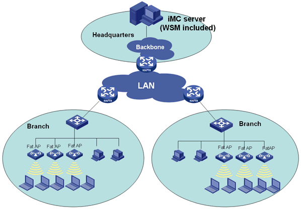
Before you create a fat AP network in WSM, complete the following tasks:
· Configure the fat AP so that it can access the network.
· Configure SNMP communities on the fat AP, and specify the WSM server host (by IP address) as the management console of the fat AP.
· Add the fat AP to the IMC platform.
To create a fat AP network in WSM:
1. Add WLANs in batches for the fat APs, and bind the WLANs to the radios of the fat APs so that the fat APs can provide wireless service.
For more information about configuring WLANs, see "Configuring WLANs in batches."
2. Optional: Configure the same parameters for more radios in batches on the fat AP to reduce repetitive operations and improve efficiency.
For more information about configuring radios in batches, see "Configuring radios in batches."
Viewing the fat AP list
The Fat AP List page displays information about all managed fat APs in IMC, including the fat AP status, device label, model, IP address, number of online clients, last synchronization time, and synchronization result.
To view the fat AP list:
1. Click the Service tab.
2. From the navigation tree, select WLAN Manager > Resource Management > Fat APs.
The Fat AP List page displays all fat APs.
Device List
¡ Status—Current alarm status of the fat AP.
¡ Device Label—Device label that identifies the fat AP in the IMC platform.
Click the device label of a fat AP to
view its details. A device label that carries a Warning icon ![]() indicates that
the management console of the fat AP is not the WSM server host, and that some
of the management functions in IMC (such as adding, modifying or deleting
WLANs) are not available for the fat AP. To solve this problem, operators can
log into the Web Manager of the fat AP, specify the WSM server host (by IP
address) as the fat AP's management console, and then synchronize the fat AP.
After that, the Warning icon
indicates that
the management console of the fat AP is not the WSM server host, and that some
of the management functions in IMC (such as adding, modifying or deleting
WLANs) are not available for the fat AP. To solve this problem, operators can
log into the Web Manager of the fat AP, specify the WSM server host (by IP
address) as the fat AP's management console, and then synchronize the fat AP.
After that, the Warning icon ![]() disappears.
disappears.
¡ Model—Model of the fat AP.
¡ IP Address—Management IP address of the fat AP.
¡ Clients—Number of clients that are associated with the fat AP.
Click the number to view all of the online clients.
¡ Last Sync Time—Time when the fat AP configuration was last synchronized.
¡ Sync Result—Last synchronization result: Succeeded or Failed.
¡ Operation—Click the Operation icon ![]() for the fat AP to display the operation menu.
for the fat AP to display the operation menu.
These are the operational tasks provided in the Operation menu:
- WLAN Configuration
- View Topology
- Locate to Map
- Ping
- TraceRoute
- Open Web Manager
- Monitor
- Telnet
- SSH
|
|
NOTE: The Operation menu contents for a Comware-based fat AP are different from the contents for an MSM series fat AP. |
If the Fat AP List contains enough entries, the following navigational aids are displayed:
· Click the Next Page
icon ![]() to page
forward in the Fat AP List.
to page
forward in the Fat AP List.
· Click the Last Page
icon ![]() to page
forward to the end of the Fat AP List.
to page
forward to the end of the Fat AP List.
· Click the Previous Page
icon ![]() to page
backward in the Fat AP List.
to page
backward in the Fat AP List.
· Click the First Page
icon ![]() to page
backward to the front of the Fat AP List.
to page
backward to the front of the Fat AP List.
Click 8, 15, 50, 100, or 200 at the upper right of the Fat AC List to specify the number of items you want to display on each page.
You can sort the Fat AP List by every field except the Operation field. Click the column label to sort the list by the selected field. The column label allows you to toggle between the various sort options specific to each field.
Querying fat APs
WSM provides basic query and advanced query. Basic query criteria include several key parameters for quick searches. Advanced query offers various query criteria for precise matching.
To query fat APs:
1. Click the Service tab.
2. From the navigation tree, select WLAN Manager > Resource Management > Fat APs.
The Fat AP List page displays all fat APs.
3. To perform a basic query:
a. Enter the device label (case-insensitive) or IP address of the fat AP.
WSM supports fuzzy matching for this field. For example, if you enter 19, all fat APs with device labels or IP addresses containing 19 are queried.
b. Click the Query icon
![]() .
.
The Device List displays all fat APs matching the query criteria.
c. Clear the Query
field, and click the Query icon ![]() to display fat
APs.
to display fat
APs.
4. To perform an advanced query:
a. Click the Expand Query
Area icon ![]() next to the Query
field to expand the Query area. Click it again to
hide the Query area.
next to the Query
field to expand the Query area. Click it again to
hide the Query area.
b. Enter or select one or more of the following query criteria:
¡ Device Label—Enter the device label of the fat AP. WSM supports fuzzy matching for this field.
¡ IP Address—Enter a partial or complete IPv4 address of the fat AP. WSM supports fuzzy matching for this field.
¡ Radio Type—Select a radio type from the list. Options are:
- All
- 802.11a
- 802.11b
- 802.11g
- 802.11bg
- 802.11at
- 802.11an
- 802.11gn
- 802.11n (2.4GHz)
- 802.11bgn
- 802.11n
- 802.11n(5GHz)
¡ Channel—Enter the channel used by the fat AP. WSM supports fuzzy matching for this field.
¡ SSID—Enter the SSID of the WLAN. WSM supports fuzzy matching for this field.
¡ Device Status—Select a device state for the fat AP. Options are:
- Unlimited
- Critical
- Major
- Minor
- Warning
- Normal
- Unmanaged
- Unknown
¡ Connectivity Status—Select a connectivity state for the fat AP. Options are Unlimited, Reachable, and Unreachable.
¡ Vendor—Select the vendor of the fat AP. Options are Unlimited, H3C, HP, and Cisco.
¡ Location—Enter or select the name of the location view to which the fat AP belongs. WSM supports fuzzy matching for this field.
An empty field or a field that is set to Unlimited does not serve as a query criterion.
c. Click Query.
The Fat AP List displays all fat APs matching the query criteria.
d. Click Reset to clear the query criteria and display all fat APs.
Viewing detailed information about a fat AP
1. Click the Service tab.
2. From the navigation tree, select WLAN Manager > Resource Management > Fat APs.
The Fat AP List page displays all fat APs.
3. Click the device label of an MSM series fat AP.
The fat AP details page opens.
This information only describes the wireless service information about the fat AP. For other information displayed on the fat AP details page, see H3C IMC v7.3 Enterprise and Standard Platform Administrator Guide.
4. Click the Wireless Service Information tab.
All wireless service information for the fat AP appears.
Client Information
¡ Online Clients—Number of clients that are associated with the fat APs. Click the number to view all online clients.
Radio Information
This area lists the radio information for the selected fat AP.
¡ ID—ID of the radio. Click the ID to view the radio details.
¡ Interface—Interface of the radio on the fat AP.
¡ Radio Type—Type of the radio. Options are:
- 802.11a
- 802.11b
- 802.11g
- 802.11bg
- 802.11at
- 802.11an
- 802.11gn
- 802.11n (2.4GHz)
- 802.11bgn
- 802.11n
- 802.11n(5GHz)
¡ Channel—Working channel of the radio. If this field displays Auto, If you select Auto, the fat AP evaluates the channel quality and selects an optimum channel as the working channel.
¡ Current Transmission Power (dBm)—Current transmit power of the radio.
¡ Modify—Click the Modify icon ![]() of a radio to display
the page for modifying the radio parameters. For more information, see "Modifying the radio parameters for a fat AP."
of a radio to display
the page for modifying the radio parameters. For more information, see "Modifying the radio parameters for a fat AP."
Configuring WLANs in batches
WLAN configuration allows you to configure the VSC for fat APs. After being bound to radios on a fat AP, a WLAN deploys the VSC to fat APs so they can provide wireless services for clients.
More fat APs can use the same WLAN to provide wireless service for clients. To facilitate WLAN configuration and reduce repetitive operations, you can use the batch mode to create, modify, or delete the WLANs for more fat APs in batches.
Creating WLANs in batches
This function allows you to create, in batches, the WLANs for multiple fat APs, and bind the WLANs with radios of the fat APs.
To create WLANs for multiple fat APs in batches:
1. Click the Service tab.
2. From the navigation tree, select WLAN Manager > Configuration Management.
The Configuration Management page opens.
3. Click the MSM tab.
4. In the Fat AP Batch Configuration Management (HP) area, click WLAN Batch Configuration.
The Batch Create WLANs page opens.
|
|
NOTE: The Fat AP Batch Configuration Management (HP) area appears on the configuration management page only after at least one MSM series fat AP has been added to the IMC platform. |
5. Configure the basic information for the WLAN:
¡ VSC Name—Enter the name of the VSC.
¡ SSID—Enter the unique SSID of the WLAN, a string of 1 to 32 characters. For a list of valid characters, see "Adding a WLAN."
¡ Status—Select a state for the WLAN. Options are Enable and Disable. Only WLANs in the Enable state can provide wireless service.
¡ VLAN Tagging—Specify whether the WLAN can be bound to a VLAN.
¡ VLAN ID—Select the VLAN ID bound to the WLAN. All wireless clients that access the WLAN are added automatically to the bound VLAN. This field is configurable only when VLAN Tagging is set to Enable.
¡ Tagged port—Select a VLAN type. Option is Port_1. This field is configurable only when VLAN Tagging is set to Enable.
¡ Broadcast SSID—Specify whether fat APs can broadcast the SSID in beacon frames. If you select Enable, fat APs bound with the WLAN periodically advertise their presence by broadcasting their SSIDs in beacon frames. If you select Disable, the fat APs do not broadcast their SSIDs.
¡ Inter-Client Blocking—Enable or disable access between clients that access the WLAN.
6. Configure the security information for the WLAN:
¡ Encryption—Select an encryption mode for the WLAN. Options are:
- None
- Static WEP
- Dynamic WEP
- WPA Pre-Shared Key
- WPA Dynamic
For each encryption mode, you need to specify different parameters, as described in Table 12.
Table 12 Security information parameters
|
Encryption |
Security information parameters |
|
None |
No security parameters need to be configured. |
|
Static WEP |
· Key Length—Select the key length from the list. Options are 64 bits and 128 bits. · Key Type—Select the key type from the list. Options are ASCII and HEX. · Key Index—Select the key index from the list. Options are 1, 2, 3, and 4. · Key—Enter the value of the key. Valid value range is determined by Key Length and Key Type. For more information, see Table 14. |
|
Dynamic WEP |
No security parameters need to be configured. |
|
WPA Pre-Shared Key |
· Version—Select a WPA version from the list. Options are WPA, WPA2, and WPA or WPA2. The default cipher value varies with the WPA version. For more information, see Table 14. · Cipher—Select a link layer encryption protocol from the list. Options are TKIP, CCMP (AES), and TKIP+CCMP (AES). The parameter is determined by Encryption and Version. ¡ TKIP—Temporal key integrity protocol uses the RC4 algorithm as WEP does, but provides more secure protection for WLAN. ¡ CCMP (AES)—Counter mode with CBC-MAC protocol is a Counter-Mode/CBS-MAC mechanism based on advanced encryption standard (AES) to provide high security. · Key Type—Key type defaults to ASCII, which cannot be modified. · Pre-Shared Key—Enter the pre-shared key. |
|
WPA Dynamic |
· Version—Select a WPA version from the list. Options are WPA, WPA2, and WPA or WPA2. The default cipher value varies with WPA versions. For more information, see Table 14. · Cipher—Select a link layer encryption protocol from the list. Options include TKIP, CCMP (AES), and TKIP+CCMP (AES). The parameter is determined by Encryption and Version. |
Table 13 shows the key value ranges.
|
Key type |
64 bits |
128 bits |
|
ASCII |
A string of 5 alphanumeric characters |
A string of 13 alphanumeric characters |
|
HEX |
A 10-digit hexadecimal number |
A 26-digit hexadecimal number |
Table 14 shows the cipher default values.
Table 14 Cipher default values
|
Version |
Cipher default value (cannot be modified) |
|
WPA |
TKIP |
|
WPA2 |
CCMP (AES) |
|
WPA or WPA2 |
TKIP + CCMP (AES) |
7. Configure the following authentication parameters as needed:
¡ Authentication Mode—Select an authentication mode for the WLAN. Options are:
- None
- HTML Authentication
- MAC Authentication
- 802.1X Authentication
For each authentication mode, you need to specify different parameters. For more information, see Table 6.
8. Configure the following filter parameters as needed:
¡ Wireless MAC Filter—Enable MAC address filtering.
- MAC Address List—Select a MAC address list.
- Filter Action—Select a filtering action. Options are Allow and Block. If you select Allow, only clients whose MAC addresses are in the MAC address list are allowed to access the WLAN. If you select Block, clients whose MAC addresses are in the MAC address list are forbidden to access the WLAN.
¡ Wireless IP Filter—Enable IP address filtering.
- IP Address—Enter an IP address.
- Mask—Enter a subnet mask for the IP address.
Click Add to add the network segment to the IP address list. Clients whose IP addresses are within network segments in the IP address list are allowed to access the WLAN. You can select a network segment from the list and click Delete to delete it.
9. Configure the radio binding information:
¡ Radio Behavior—Select the radios bound to the WLAN. Options are Both Radios, Radio 1 Only, and Radio 2 Only.
10. In the Selected Devices area, select the fat APs on which you want to create the WLANs. Options are All Fat APs and Selected Fat APs.
¡ All Fat APs—Select this option to create the WLANs on all managed fat APs in IMC. Then go to step 14.
¡ Selected Fat APs—Select this option to create the WLANs only on the selected fat APs.
If the Selected Fat APs option is selected, the page refreshes to displays the Fat AP List area.
11. In the Fat AP List area, click Add to display the Select Devices dialog box.
12. Specify one or more of the following query criteria to search for the fat APs you want to bind to the WLAN:
¡ Device Label—Enter the label of the fat AP. WSM supports fuzzy matching for this field.
¡ IP Address—Enter the IPv4 address of the fat AP. WSM supports fuzzy matching for this field.
¡ Model—Enter the model of the fat AP. WSM supports fuzzy matching for this field.
¡ Connectivity Status—Select a connectivity state for the fat AP. Options are Unlimited, Reachable, and Unreachable.
¡ Location—Enter or select the name of the location view to which the fat AP belongs. WSM supports fuzzy matching for this field.
An empty field or a field that is set to Unlimited does not serve as a query criterion.
13. Click Query.
The Fat AP List displays all fat APs matching the query criteria. To clear the query criteria and display all fat APs, click Reset.
|
|
NOTE: To avoid configuration failures, configure fat APs of the same model in batches. If the fat APs are of more models, configure fat APs of each model separately. |
14. Select the desired fat APs.
15. Click OK.
The selected fat APs appear in the Fat AP List on the Batch Create WLANs page.
16. Click OK.
WSM starts creating the WLANs on the selected fat APs, and displays the operation results when the operation is complete.
17. Click Back to return to the Batch Create WLANs page.
Modifying WLANs in batches
This function allows you to modify, in batches, the WLANs with the same SSID created on multiple fat APs. Before the operation, make sure the WLAN with the specified SSID exists on the target fat AP.
To modify WLANs in batches:
1. Click the Service tab.
2. From the navigation tree, select WLAN Manager > Configuration Management.
The Configuration Management page opens.
3. Click the MSM tab.
4. In the Fat AP Batch Configuration Management (HP) area, click WLAN Batch Configuration.
|
|
NOTE: The Fat AP Batch Configuration Management (HP) area appears on the configuration management page only after at least one MSM series fat AP has been added to the IMC platform. |
5. In the WLAN Batch Configuration area, click Batch Modify WLANs.
The Batch Modify WLANs page opens.
6. Modify the WLAN parameters as needed. For information about the WLAN parameters, see "Creating WLANs in batches."
7. In the Selected Devices area, select the fat APs on which you want to modify the WLANs. Options are All Fat APs and Selected Fat APs.
¡ All Fat APs—Select this option to modify the WLANs with the specified SSID on all managed fat APs in IMC. Then go to step 13.
¡ Selected Fat APs—Select this option to modify the WLANs with the specified SSID only on the selected fat APs.
If the Selected Fat APs option is selected, the page refreshes to displays the Fat AP List area.
8. In the Fat AP List area, click Add to display the Select Devices dialog box.
9. Specify one or more of the following query criteria to search for the fat APs on which the WLAN is to be modified:
¡ Device Label—Enter the label of the fat AP. WSM supports fuzzy matching for this field
¡ IP Address—Enter the IPv4 address of the fat AP. WSM supports fuzzy matching for this field.
¡ Model—Enter the model of the fat AP. WSM supports fuzzy matching for this field
¡ Connectivity Status—Select a connectivity state for the fat AP. Options are Unlimited, Reachable, and Unreachable.
¡ Location—Enter or select the name of the location view to which the fat AP belongs. WSM supports fuzzy matching for this field.
An empty field or a field that is set to Unlimited does not serve as a query criterion.
10. Click Query.
The Fat AP List displays all fat APs matching the query criteria. To clear the query criteria and display all fat APs, click Reset.
|
|
NOTE: To avoid configuration failures, configure fat APs of the same model in batches. If the fat APs are of different models, configure fat APs of each model separately. |
11. Select the desired fat APs.
12. Click OK.
The selected fat APs appear in the Fat AP List.
13. Click OK.
WSM starts modifying the WLANs on the selected fat APs, and displays the operation results when the operation is complete.
14. Click Back to return to the Batch Modify WLANs page.
Deleting WLANs in batches
This function allows you to delete, in batches, the WLANs with the same SSID on multiple fat APs. Before the operation, make sure the WLAN with the specified SSID exists on the target fat AP.
To delete WLANs in batches:
1. Click the Service tab.
2. From the navigation tree, select WLAN Manager > Configuration Management.
The Configuration Management page opens.
3. Click the MSM tab.
4. In the Fat AP Batch Configuration Management (HP) area, click WLAN Batch Configuration.
5. In the WLAN Batch Configuration area, click Batch Delete WLANs.
The Batch Delete WLANs page opens.
|
|
NOTE: The Fat AP Batch Configuration Management (HP) area appears on the configuration management page only after at least one MSM series fat AP is added to the IMC platform. |
6. Enter the SSIDs of the WLANs you want to delete in the SSID field.
The string must be 1 to 32 characters in length, and can include digits, letters, and special characters such as the following:
¡ Tilde (~)
¡ At sign (@)
¡ Dollar sign ($)
¡ Percent sign (%)
¡ Caret (^)
¡ Asterisk (*)
¡ Left brace({)
¡ Right brace (})
¡ Left parenthesis (()
¡ Right parenthesis ())
¡ Left bracket ([)
¡ Right bracket (])
¡ Hyphen (-)
¡ Underscore(_)
¡ Plus sign (+)
¡ Equal sign (=)
¡ Question mark (?)
¡ Vertical bar (|)
¡ Colon (:)
¡ Semi-colon (;)
¡ Apostrophe (')
¡ Comma (,)
¡ Dot (.)
¡ Spaces
The SSID cannot be null and cannot be the same as any existing SSID.
7. In the Selected Devices area, select the fat APs with the WLANs you want to delete. Options are All Fat APs and Selected Fat APs.
¡ All Fat APs—Select this option to delete the WLANs with the specified SSID on all managed fat APs in IMC. Then go to step 13.
¡ Selected Fat APs—Select this option to delete the WLANs with the specified SSID only on the selected fat APs.
If the Selected Fat APs option is selected, the page refreshes to display the Fat AP List area.
8. In the Fat AP List area, click Add to display the Select Devices dialog box.
9. Specify one or more of the following query criteria to search for the fat APs with the WLAN you want to delete:
¡ Device Label—Enter the label of the fat AP. WSM supports fuzzy matching for this field.
¡ IP Address—Enter the IPv4 address of the fat AP. WSM supports fuzzy matching for this field.
¡ Model—Enter the model of the fat AP. WSM supports fuzzy matching for this field.
¡ Connectivity Status—Select a connectivity state for the fat AP. Options are Unlimited, Reachable, and Unreachable.
¡ Location—Enter or select the name of the location view to which the fat AP belongs. WSM supports fuzzy matching for this field.
An empty field or a field that is set to Unlimited does not serve as a query criterion.
10. Click Query.
The Fat AP List displays all fat APs matching the query criteria. To clear the query criteria and display all fat APs, click Reset.
11. Select the fat APs with the WLAN you want to delete.
12. Click OK.
The selected fat APs appear in the Fat AP List.
13. Click OK.
WSM starts deleting the WLANs with the specified SSID on the selected fat APs, and displays the operation results when the operation is complete.
14. Click Back to return to the Batch Delete WLANs page.
Configuring radios in batches
To facilitate radio configuration and reduce repetitive operations, WSM enables you to configure, in batches, the public parameters for more radios of the fat APs.
Parameters include the following:
· Radio type
· Channel in use
· Administrative status
· Maximum transmit power
· Operating mode
· Description
To configure radios in batches:
1. Click the Service tab.
2. From the navigation tree, select WLAN Manager > Configuration Management.
The Configuration Management page opens.
3. Click the MSM tab.
4. In the Fat AP Batch Configuration Management (HP) area, click Radio Batch Configuration.
The Radio Batch Configuration page opens.
|
|
NOTE: The Fat AP Batch Configuration Management (HP) area appears on the configuration management page only after the MSM series fat AP is added to the IMC platform. |
5. Select the boxes to the left of the parameters to be configured, and enter the parameters as required.
¡ Radio Type—Select a radio type from the list. Options are:
- 802.11a
- 802.11b
- 802.11g
- 802.11bg
- 802.11at
- 802.11an
- 802.11gn
- 802.11n (2.4GHz)
- 802.11bgn
- 802.11n
- 802.11n(5GHz)
¡ Channels in Use—Select the working channel of the radio. The value range depends on the radio type. If you select Auto, the fat AP evaluates the channel quality and selects an optimum channel as the working channel.
¡ Admin Status—Select an administrative state for the radio. Options are Up and Down. Radios in Down state do not transmit wireless signals.
¡ Transmission Power—Enter the maximum transmit power of the radio. The value range depends on the device model.
¡ Operating Mode—Select the operating mode of the radio. Options are:
- Access Point and Local Mesh
- Access Point Only
- Local Mesh Only
- Monitor
- Sensor
The value range depends on the device model.
¡ Description—Enter a description for the radio.
6. In the Selected Radios area, select the radios you want to configure. Options are All Radios and Selected Radios.
¡ All Radios—Select this option to configure all radios. Then go to step 12.
¡ Selected Radios—Select this option to configure only the selected radios.
If the Selected Radios option is selected, the page refreshes to displays the Radio List area.
7. In the Radio List area, click Add to display the Select Radio dialog box.
8. Enter or select one or more of the following query criteria to search for the radios you want to configure:
¡ AP Label—Enter the label of the fat AP to which the radio belongs. WSM supports fuzzy matching for this field
¡ IP Address—Enter the IPv4 address of the fat AP. WSM supports fuzzy matching for this field.
¡ Model—Enter the model of the fat AP to which the radio belongs. WSM supports fuzzy matching for this field.
¡ Radio Type—Select a radio type. Options are:
- All
- 802.11a
- 802.11b
- 802.11g
- 802.11bg
- 802.11at
- 802.11an
- 802.11gn
- 802.11n (2.4GHz)
- 802.11bgn
- 802.11n
- 802.11n(5GHz)
¡ Location—Enter or select the name of the location view to which the fat AP belongs. WSM supports fuzzy matching for this field.
An empty field or a field that is set to Unlimited does not serve as a query criterion.
9. Click Query.
The Radio List displays all radios that match the query criteria. Click Reset to clear the query criteria and display all radios.
|
|
NOTE: To avoid configuration failures, use batch mode to configure radios on fat APs of the same model. |
10. Select the radios you want to configure.
11. To close the Select Radio window, click OK.
The Radio List displays all of the selected radios.
12. Click OK.
WSM starts configuring the selected radios, and displays the operation results when the operation is complete.
13. To return to the Radio Batch Configuration page, click Back.
Managing WLANs
WLANs allow you to configure the VSC for fat APs. After being bound to radios on a fat AP, a WLAN deploys the VSC to fat APs so they can provide wireless services for clients.
You can access the WLAN configuration feature from the Fat AP List page or the Fat AP Details page. This information uses the Fat AP List page as an example.
Viewing WLANs on an HP fat AP
1. Click the Service tab.
2. From the navigation tree, select WLAN Manager > Resource Management > Fat APs.
The Fat AP List page displays all fat APs.
3. Click the Operation
icon ![]() of an MSM
series fat AP.
of an MSM
series fat AP.
4. From the menu, select WLAN Configuration.
The WLAN List and Radio List display all WLANs and radios on the fat AP.
WLAN List
¡ SSID—SSID of the WLAN. Click the SSID of a WLAN to view its details.
¡ Status—State of the WLAN. Options are Enable and Disable. A WLAN can provide wireless services only when it is in the Enable state.
¡ VLAN ID—VLAN ID bound to the WLAN. Clients that access the WLAN are added automatically to the bound VLAN.
¡ Encryption Mode—Encryption mode used by the WLAN. Options are:
- None
- Static WEP
- Dynamic WEP
- WPA Pre-Shared Key
- WPA Dynamic
This parameter must be configured on the web manager of the fat AP.
¡ Authentication Mode—Authentication mode used by the WLAN. Options are:
- None
- HTML Authentication
- 802.1X Authentication
- MAC Authentication.
This parameter must be configured on the web manager of the fat AP.
¡ Broadcast SSID—Whether to enable fat APs to broadcast their SSIDs. Options are:
- Enable—indicates that the fat APs bound with the WLAN will broadcast their SSIDs so that they can be discovered by clients.
- Disable—indicates that the fat APs do not support SSID broadcasting.
¡ Operation—Click the Operation icon ![]() to display the operation menu.
to display the operation menu.
From the Operation menu, you can modify and delete the specified WLAN.
Radio List
¡ Radio ID—ID of the radio. Click the ID to view the radio details.
¡ Description—Description for the radio.
¡ Radio Type—Type of the radio. Options are:
- All, 802.11a
- 802.11b
- 802.11g
- 802.11bg
- 802.11at
- 802.11an
- 802.11gn
- 802.11n (2.4GHz)
- 802.11bgn
- 802.11n
- 802.11n(5GHz)
¡ Admin Status—Administrative state of the radio. Options are Up and Down.
¡ Channel—Working channel of the radio. If this field displays Auto, a fat AP selects an idle channel as the working channel.
¡ Current Transmission Power (dBm)—Current transmit power of the radio.
¡ RF Detection—RF neighbor detection mode: Periodic or Dedicated.
¡ Modify—Click the Modify icon ![]() of a radio to enter the page for modifying the radio parameters. For
more information about modifying fat AP radio parameters, see "Modifying the radio parameters for a fat AP."
of a radio to enter the page for modifying the radio parameters. For
more information about modifying fat AP radio parameters, see "Modifying the radio parameters for a fat AP."
Viewing detailed information about a WLAN on a fat AP
1. Click the Service tab.
2. From the navigation tree, select WLAN Manager > Resource Management > Fat APs.
The Fat AP List page displays all fat APs.
3. Click the Operation
icon ![]() of an MSM
series fat AP.
of an MSM
series fat AP.
4. From the menu, select WLAN Configuration.
The WLAN List displays all WLANs on the fat AP.
5. Click the SSID of the WLAN whose detailed information you want to view.
The WLAN Details window opens.
WLAN Details
Basic Information
¡ VSC Name—Name of the VSC.
¡ SSID—SSID of the WLAN.
¡ Status—State of the WLAN. Options are Enable and Disable. A WLAN can provide wireless services only when it is in the Enable state.
¡ VLAN Tagging—Whether the WLAN can be bound to a VLAN.
¡ VLAN ID—ID of the VLAN bound to the WLAN. Wireless clients that access the WLAN are added automatically to the bound VLAN. This field is empty if VLAN Tagging is set to Disable.
¡ Tagged port—Select a VLAN type. Option is Port_1. This field is configurable only when VLAN Tagging is set to Enable.
¡ Broadcast SSID—Whether to enable fat APs to broadcast their SSIDs. Options are:
- Enable—Indicates that the fat APs bound with the WLAN will broadcast their SSIDs so that they can be discovered by clients.
- Disable—Indicates that the fat APs do not support broadcasting SSIDs, and the clients must be configured manually with an SSID to access the wireless network.
¡ Inter-Client Blocking—Enable or disable access between clients that access the WLAN.
Security Information
¡ Encryption—The following encryption modes are used by the WLAN. Options are:
- None
- Static WEP
- Dynamic WEP
- WPA Pre-Shared Key
- WPA Dynamic
The following parameters appear, depending on the encryption mode:
¡ Key Length—Length of the key. Options are 64 bits and 128 bits.
¡ Key Type—Type of the key. Options are ASCII and HEX.
¡ Key Index—Index of the key. Options are 1, 2, 3, and 4.
¡ Key—Key value.
¡ Version—WPA version. Options are WPA, WPA2, and WPA + WPA2.
¡ Cipher—Link layer encryption protocol. Options are TKIP, CCMP (AES), and TKIP+CCMP (AES).
¡ Pre-Shared Key—Pre-shared key.
For the compatibility matrix of the security parameters, see Table 12.
Primary Authentication Server
¡ Address—IP address or domain name of the primary authentication server.
¡ Port—Authentication port of the primary authentication server.
¡ Secret—Password used for communication between the fat AP and the primary authentication server.
¡ Retry Interval(s)—Time that the fat AP must wait before retrying to connect to the primary authentication server after a connection times out.
¡ Retry Timeout(s)—Whether the response timeout timer is enabled, and if yes, the specified response timeout time.
Secondary RADIUS Server
¡ Secondary RADIUS Server—Whether to enable the secondary authentication server.
¡ Address—IP address or domain name of the secondary authentication server.
¡ Secret—Password used for communication between the AC and the secondary authentication server.
Radio Binding Information
¡ Radio Behavior—Radios bound to WLAN. Options are Both Radios, Radio 1 Only, and Radio 2 Only.
6. Click Close.
Adding a WLAN
This function allows you to add a WLAN to the specified fat AP, and bind the WLAN to the radios of the fat AP.
To add a WLAN to the specified fat AP:
1. Click the Service tab.
2. From the navigation tree, select WLAN Manager > Resource Management > Fat APs.
The Fat AP List page displays all fat APs.
3. Click the Operation
icon ![]() of an MSM
series fat AP.
of an MSM
series fat AP.
4. From the menu, select WLAN Configuration.
The WLAN List displays all WLANs on the fat AP.
5. Click Add.
6. Configure basic information for the WLAN:
¡ VSC Name—The name of the VSC.
¡ SSID—Enter the SSID of the WLAN, a string of 1 to 32 characters.
The string can include digits, letters, and special characters such as the following:
- Tilde (~)
- At sign (@)
- Dollar sign ($)
- Percent sign (%)
- Caret (^)
- Asterisk (*)
- Left brace({)
- Right brace (})
- Left parenthesis (()
- Right parenthesis ())
- Left bracket ([)
- Right bracket (])
- Hyphen (-)
- Underscore(_)
- Plus sign (+)
- Equal sign (=)
- Question mark (?)
- Vertical bar (|)
- Colon (:)
- Semi-colon (;)
- Apostrophe (')
- Comma (,)
- Dot (.)
- Spaces
The SSID cannot be null and cannot be the same as any existing SSID.
¡ Status—Select a WLAN state from the list. Options are Enable and Disable. A WLAN can provide wireless services only when it is in the Enable state.
¡ Broadcast SSID—Select whether to enable fat APs to broadcast their SSIDs. Options are:
- Enable—Indicates the fat APs bound with the WLAN will broadcast their SSIDs so that they can be discovered by clients.
- Disable—Indicates the fat APs do not support broadcasting SSIDs, and the clients must be configured manually with an SSID to access the wireless network.
¡ VLAN Tagging—Select whether to enable the WLAN to be bound to a VLAN. Options are Enable and Disable.
¡ VLAN ID—This field is configurable only when VLAN Tagging is set to Enable. Select the VLAN ID bound to the WLAN. All wireless clients that access the WLAN are added automatically to the bound VLAN.
¡ Tagged port—Select a VLAN type. Option is Port_1. This field is configurable only when VLAN Tagging is set to Enable.
¡ Inter-Client Blocking—Enable or disable access between clients that access the WLAN.
7. Configure the security parameters for the WLAN:
¡ Encryption—Select an encryption mode for the WLAN. Options are:
- None
- Static WEP
- Dynamic WEP
- WPA Pre-Shared Key
- WPA Dynamic
For different encryption modes, you need to specify different parameters. For more information, see Table 12.
8. Configure the following authentication parameters as needed:
¡ Authentication Mode—Select an authentication mode for the WLAN. Options are:
- None
- HTML Authentication
- MAC Authentication
- 802.1X Authentication
For each authentication mode, you need to specify different parameters. For more information, see Table 6.
9. Configure the following filter parameters as needed:
¡ Wireless MAC Filter—Enable MAC address filtering.
- MAC Address List—Select a MAC address list.
- Filter Action—Select a filtering action. Options are Allow and Block. If you select Allow, only clients whose MAC addresses are in the MAC address list are allowed to access the WLAN. If you select Block, clients whose MAC addresses are in the MAC address list are forbidden to access the WLAN.
¡ Wireless IP Filter—Enable IP address filtering.
- IP Address—Enter an IP address.
- Mask—Enter a subnet mask for the IP address.
Click Add to add the network segment to the IP address list. Clients whose IP addresses are within network segments in the IP address list are allowed to access the WLAN. You can select a network segment from the list and click Delete to delete it.
10. Configure the radio binding parameters for the WLAN:
¡ Radio Behavior—Select the radios bound to the fat APs. Options are Both Radios, Radio 1 Only, and Radio 2 Only.
11. Click OK.
Modifying a WLAN
This function allows you to modify a WLAN on the specified fat AP, and reselect the radios bound to the WLAN.
To modify a WLAN on the specified fat AP:
1. Click the Service tab.
2. From the navigation tree, select WLAN Manager > Resource Management > Fat APs.
The Fat AP List page displays all fat APs.
3. Click the Operation
icon ![]() for an MSM
series fat AP.
for an MSM
series fat AP.
4. From the menu, select WLAN Configuration.
The WLAN List displays all WLANs on the fat AP.
5. Click the Operation icon ![]() for a WLAN.
for a WLAN.
6. From the menu, select Modify.
The page for modifying the WLAN opens.
7. Modify the basic information parameters for the WLAN:
¡ VSC Name—Modify the VSC name.
¡ SSID—Modify the SSID of the WLAN, a string of 1 to 32 characters. The string can include digits, letters, special characters such as the following:
- Tilde (~)
- At sign (@)
- Dollar sign ($)
- Percent sign (%)
- Caret (^)
- Asterisk (*)
- Left brace({)
- Right brace (})
- Left parenthesis (()
- Right parenthesis ())
- Left bracket ([)
- Right bracket (])
- Hyphen (-)
- Underscore(_)
- Plus sign (+)
- Equal sign (=)
- Question mark (?)
- Vertical bar (|)
- Colon (:)
- Semi-colon (;)
- Apostrophe (')
- Comma (,)
- Dot (.)
- Spaces
The SSID cannot be null and cannot be the same as any existing SSID.
¡ Status—Select a WLAN state. Options are Enable and Disable. A WLAN can provide wireless services only when it is in the Enable state.
¡ Broadcast SSID—Select whether to enable fat APs to broadcast their SSIDs. Options are:
- Enable—Indicates that the fat APs bound with the WLAN will broadcast their SSIDs so that they can be discovered by clients.
- Disable—Indicates that the fat APs do not support broadcasting SSIDs, and the clients must be configured manually with an SSID to access the wireless network.
¡ VLAN Tagging—Select whether to enable the WLAN to be bound to a VLAN. Options are Enable and Disable.
¡ VLAN ID—This field is configurable only when VLAN Tagging is set to Enable. Select the VLAN ID bound to the WLAN. All wireless clients that access the WLAN are added automatically to the bound VLAN.
¡ Tagged port—Select a VLAN type. Option is Port_1. This field is configurable only when VLAN Tagging is set to Enable.
¡ Inter-Client Blocking—Enable or disable access between clients that access the WLAN.
8. Modify the security parameters for the WLAN:
¡ Encryption—Select an encryption mode for the WLAN. Options are:
- None
- Static WEP
- Dynamic WEP
- WPA Pre-Shared Key
- WPA Dynamic
For different encryption modes, you need to specify different parameters. For more information, see Table 12.
9. Modify the authentication parameters for the WLAN:
¡ Authentication Mode—Select an authentication mode for the WLAN. Options are:
- None
- HTML Authentication
- MAC Authentication
- 802.1X Authentication
For each authentication mode, you need to specify different parameters. For more information, see Table 6.
10. Modify the filter parameters for the WLAN:
¡ Wireless MAC Filter—Enable MAC address filtering.
- MAC Address List—Select a MAC address list.
- Filter Action—Select a filtering action. Options are Allow and Block. If you select Allow, only clients whose MAC addresses are in the MAC address list are allowed to access the WLAN. If you select Block, clients whose MAC addresses are in the MAC address list are forbidden to access the WLAN.
¡ Wireless IP Filter—Enable IP address filtering.
- IP Address—Enter an IP address.
- Mask—Enter a subnet mask for the IP address.
Click Add to add the network segment to the IP address list. Clients whose IP addresses are within network segments in the IP address list are allowed to access the WLAN. You can select a network segment from the list and click Delete to delete it.
11. Modify the radio binding parameters for the WLAN:
¡ Radio Behavior—Select the radios bound to the fat APs. Options are Both Radios, Radio 1 Only, and Radio 2 Only.
12. Click OK.
Deleting a WLAN
This function allows you to delete a WLAN from the specified fat AP. Deleting a WLAN deletes all information related to the WLAN, and logs out all clients accessing the WLAN.
To delete a WLAN from the specified fat AP:
1. Click the Service tab.
2. From the navigation tree, select WLAN Manager > Resource Management > Fat APs.
The Fat AP List page displays all fat APs.
3. Click the Operation
icon ![]() for an MSM
series fat AP.
for an MSM
series fat AP.
4. From the menu, select WLAN Configuration.
The WLAN List displays all WLANs on the fat AP.
5. Click the Operation icon ![]() for a WLAN.
for a WLAN.
6. From the menu, select Delete.
A confirmation dialog box opens.
7. Click OK.
Synchronizing fat APs
WSM allows you to synchronize fat AP configuration automatically or manually. By default, IMC automatically synchronizes fat APs every 2 hours.
For more information, see the description about using batch mode to configure polling interval in the H3C IMC v7.3 Enterprise and Standard Platform Administrator Guide. You can also manually synchronize fat APs.
To manually synchronize fat APs:
1. Click the Service tab.
2. From the navigation tree, select WLAN Manager > Resource Management > Fat APs.
The Fat AP List page displays all fat APs.
3. Select the fat APs you want to synchronize.
4. Click Synchronize to start synchronizing the selected fat APs.
After the process is complete, the refreshed page displays the latest fat AP information.
Exporting fat APs
WSM allows you to export all fat APs in the fat AP list to a .csv file, which is saved on your local computer.
To export all fat APs:
1. Click the Service tab.
2. From the navigation tree, select WLAN Manager > Resource Management > Fat APs.
The Fat AP List page displays all fat APs.
3. Click Export All.
4. Click Export Result to download, and save the exported file to your local computer.
Viewing detailed information about a radio on a fat AP
1. Click the Service tab.
2. From the navigation tree, select WLAN Manager > Resource Management > Fat APs.
The Fat AP List page displays all fat APs.
3. Click the device label of an MSM series fat AP.
4. Click the Wireless Service Information tab.
All wireless service information for the selected fat AP appears on this tab.
5. On the radio list, click the ID of the radio whose detailed information you want to view.
A page opens and displays detailed radio information.
Fat AP Radio Details
Basic Information
¡ Radio ID—ID of the radio.
¡ Status—Administrative state of the radio. Options are UP and Down.
¡ Country/Region Code—Code of the country or region where the fat AP belongs.
Network
¡ Multicast Tx Data Rate (Mbps)—Transmit rate for multicast and broadcast traffic. This is a fixed rate, which means that if a station is too far away to receive traffic at this rate, the multicast is not seen by the station.
¡ Beacon Interval (TU)—Number of TUs that the fat AP waits between transmits of the wireless beacon. One TU equals 1024 microseconds.
¡ Use RTS Threshold—Enable or disable the RTS threshold. Enabling the RTS threshold allows you to control collisions on the link that can reduce throughput.
¡ RTS Threshold (B)—Use this parameter to control collisions on the link that can reduce throughput.
RF Coverage
¡ Radio Operating Mode—Operating mode of the radio. Options are:
- Access Point and Local Mesh—Standard operating mode provides support for all wireless functions.
- Access Point Only—Only provides access point functionality. Local mesh links cannot be created.
- Local Mesh Only—Only provides local mesh functionality. Wireless client stations cannot connect.
- Monitor—Disables access point and local mesh functions.
- Sensor—Only monitors the wireless signals in the surrounding environment. Use this option for continuous scanning across all channels in all supported wireless modes.
¡ Band—Frequency band of the radio.
¡ Wireless Mode—Supported wireless modes are determined by the regulations of the country in which the fat AP is operating, and are controlled by the country setting on the fat AP. Options are:
- 802.11a
- 802.11b
- 802.11g
- 802.11bg
- 802.11at
- 802.11an
- 802.11gn
- 802.11n (2.4GHz)
- 802.11bgn
- 802.11n
- 802.11n(5GHz)
¡ Channel Selection—The primary channel and the channel above or below it becomes the secondary channel.
Adaptive Transmit Power Control
¡ Mode—Mode of transmit power control. Options are Manual and Auto.
¡ Max Transmission Power (dBm)—Maximum transmit power of the wireless radio, in dBm.
¡ Current Transmission Power (dBm)—Current transmit power of the wireless radio, in dBm.
RF Neighbor Detection
¡ Use Interval—Whether RF neighbor detection is enabled.
¡ Interval (s)—RF neighbor detection interval.
¡ Detection Mode—RF neighbor detection mode. Options are Periodic and Dedicated.
If Radio Operating Mode is set to Access Point and Local Mesh, Access Point Only, or Local Mesh Only, the Detection Mode is Dedicated.
If Radio Operating Mode is set to Monitor or Sensor, the Detection Mode is Periodic.
6. Click Back to return to the Fat AP Details page.
Modifying the radio parameters for a fat AP
1. Click the Service tab.
2. From the navigation tree, select WLAN Manager > Resource Management > Fat APs.
The Fat AP List page displays all fat APs.
3. Click the device label of a fat AP.
4. Click the Wireless Service Information tab.
All wireless service information for the selected fat AP appears on this tab.
5. On the Radio
Information list, click the Modify icon ![]() for a radio.
for a radio.
The Modify Fat AP Radio Parameters page opens.
6. Modify the following parameters for the radio:
¡ Radio ID—Cannot be modified.
¡ Radio Type—Select a new radio type from the list. Options are:
- 802.11a
- 802.11b
- 802.11g
- 802.11bg
- 802.11at
- 802.11an
- 802.11gn
- 802.11n (2.4GHz)
- 802.11bgn
- 802.11n
- 802.11n(5GHz)
¡ Channels in Use—Select the working channel used by the fat AP. Available channels depend on the radio type. If Auto is selected, the fat AP automatically selects an idle channel as the working channel of the radio.
¡ Admin Status—Select an administrative state for the radio. Options are Up and Down.
¡ Max Transmission Power (dBm)—Enter the maximum transmit power of the radio, in dBm.
¡ Current Transmission Power (dBm)—Current transmit power of the radio, in dBm.
¡ Operating Mode—Select the operating mode of the radio. Options are:
- Access Point Only (Periodic RF Detection)
- Access Point and Local Mesh (Periodic RF Detection)
- Local Mesh Only (Periodic RF Detection)
- Monitor (Dedicated RF Detection)
- Sensor (Dedicated RF Detection)
The value range for this parameter depends on the fat AP model.
¡ Description—Enter a description for the radio.
7. Click OK.
Monitoring a fat AP in real time
WSM allows you to view the realtime monitoring information for a fat AP from the Fat AP List page.
The monitoring information appears on various tabs, including:
· AP
· Wireless Rates
· Neighborhood Status
· Local Mesh Neighborhood
· Local Mesh Link
· Bridge Status
· Wireless Ports
To monitor a fat AP in real time:
1. Click the Service tab.
2. From the navigation tree, select WLAN Manager > Resource Management > Fat APs.
The Fat AP List page displays all fat APs.
3. Click the Operation
icon ![]() of an MSM
series fat AP.
of an MSM
series fat AP.
4. From the menu, select Monitor.
The AP Monitor window opens, displaying information about the AP.
Click the tabs to view the following information:
AP tab
¡ CPU usage (%) and memory usage (%) trend graphs—Display the CPU and memory usage trend of the fat AP in the last 150 seconds. The monitor interval automatically increases with the monitor duration.
¡ CPU Used (%)—Current CPU usage of the fat AP.
¡ Memory Used (%)—Current memory usage of the fat AP.
¡ Online Clients—Total number of online clients associated with the fat AP.
Wireless Rates tab
¡ High Throughput Rates Status (Received Packets/Transmitted Packets) List
- Device—Name of the fat AP
- Radio Index—ID of the radio.
- MAC Address—MAC address of the wireless client.
- Rx/Tx MCS—Information about users connected through any 802.11n mode. Rates are shown for each supported MCS. The size of the bar indicates the amount of traffic sent at each MCS.
¡ Legacy Rate Traffic (Received Packets/Transmitted Packets) List
- Device—Name of the fat AP.
- Radio Index—ID of the radio.
- MAC Address—MAC address of the wireless client.
- Rx/Tx MCS—Information about users connected through any 802.11 a/b/g mode. The size of the bar indicates the amount of traffic sent at each rate.
Neighborhood Status tab
¡ MAC Address—MAC address of the neighboring device.
¡ SSID—SSID of the wireless network broadcast from the neighboring device.
¡ Wireless Mode—Wireless mode used by the neighboring device, such as 802.11a, 802.11b, 802.11g, or 802.11n.
¡ Channel—Channel number being used by the neighboring device.
¡ Signal (dBm)—Strength of the radio signal.
¡ Noise (dBm)—Amount of radio interference (noise) in the radio signal path.
¡ SNR (dB)—Signal-to-Noise Ratio, in decibels.
¡ Security—Type of security used for the WLAN. Options are:
- None
- WEP
- WPA
- WPA or WPA2
- WPA2
Local Mesh Neighborhood tab
¡ Seen By—Name of the access point that discovered the neighboring device.
¡ Neighbor—Neighboring device name. This field displays the device MAC address if the device name is unknown.
¡ Serial Number—Serial number of the neighboring device.
¡ Mesh ID—Mesh ID of the access point. Mesh IDs are unique numbers that identify a series of access points that can connect to form a local mesh.
¡ Radio Index—Index of the radio being used by the access point.
¡ Channel—Channel being used by the access point.
¡ Mode—Indicates whether the access point is operating a master, slave, or alternate master.
¡ Availability—Indicates whether the access point is available to establish a link.
¡ Encryption—Type of encryption.
¡ Signal (dBm)—Strength of the remote radio signals, in dBm.
¡ Noise (dBm)—Amount of radio interference (noise), in dBm, in the radio signal path.
¡ SNR (dB)—Relative strength of the remote radio signals versus the radio interference (noise) in dBm in the radio signal path. In most environments, SNR is a good indicator of the quality of the radio link between the local and remote access points. A higher SNR value means a better quality radio link.
Local Mesh Link tab
¡ Profile—Name of the local mesh profile.
¡ Link is On—Corresponding radio where the local mesh link is located.
¡ Status—State of the local mesh link. Options are Up and Down.
¡ Idle Time—Amount of time the link has been in the idle state.
¡ Tx Rate (Mb/s)—Transfer rate for the corresponding local mesh link.
¡ Signal (dBm)—Signal strength at which the local mesh link transmits.
¡ Noise (dBm)—Amount of radio interference (noise) in the radio signal path.
¡ SNR (dB)—Relative strength of the remote radio signals versus the radio interference (noise) in the radio signal path. In most environments, SNR is a good indicator for the quality of the radio link between the local and remote nodes. A higher SNR value means a better quality radio link.
¡ Authorized—Indicates whether the remote node has authorized the local node.
¡ Tx Packets (Packets)—Number of transferred packets through the local mesh link.
¡ Tx Dropped (Packets)—Number of dropped packets by the local mesh link.
¡ Tx Errors (Packets)—Number of errors during the transmit of packets through the local mesh link.
¡ Rx Rate (Mb/s)—Reception rate of the local mesh link.
¡ Rx Packets (Packets)—Number of received packets through the local mesh link.
¡ Rx Dropped (Packets)—Number of dropped packets by the local mesh link.
¡ Remote MAC Address—Remote MAC address.
¡ Encryption—Type of encryption used on the link.
¡ Link to Master—Specifies whether the local mesh link is linked to master or not.
Bridge Status tab
¡ Bridge List
- Port—A unique ID assigned to a port. This ID cannot be changed. The last digit in the ID corresponds to the port number used in the bridge forwarding table.
- Port Status—State of the LAN port. Options are:
- Listening—Initial state. Port is not forwarding packets, but listens for other bridges.
- Learning—Bridge learns about other bridges on that port. Port is not forwarding packets.
- Forwarding—Port is forwarding packets. Bridge is operational on the port.
- Blocking—Port is not forwarding. A loop was detected in the bridging network.
- Port Type—Type of port, such as LAN, Ethernet, UDP, and GRE.
¡ Spanning Tree Protocol List
For definitions of these fields, see the following document, which is available on the Internet: ANSI/IEEE Std 802.1D, 1998 Edition - Part 3: Media Access Control (MAC) Bridges.
- Spanning Tree Protocol—Status of the spanning tree protocol.
- Bridge ID—Bridge unique identifier.
- Designated Root—MAC address of the root switch.
- Root Path Cost—Cumulative cost of all links to reach the root switch.
Table 15 shows the root path cost values.
|
Bandwidth |
STP cost value |
|
4 Mb/s |
250 |
|
10 Mb/s |
100 |
|
16 Mb/s |
62 |
|
45 Mb/s |
39 |
|
100 Mb/s |
19 |
|
155 Mb/s |
14 |
|
622 Mb/s |
6 |
|
1 Gb/s |
4 |
|
10 Gb/s |
2 |
|
100 Gb/s |
0 |
- Max Age (s)—Maximum time that a bridge protocol data unit is saved.
- Hello Time (s)—Time between periodic configuration bridge protocol data units.
- Forward Delay (s)—Time spent in the listening and learning states.
- Topology Change Flag—Changes to the active topology.
Wireless Ports tab
¡ Port Status List
- Channel—Current channel being used.
- Frequency—Radio channel frequency.
- Wireless Mode—Wireless protocol (such as 802.11b) used by the radio.
- Operating Mode—Options are AP, AP and Local Mesh, Local Mesh, Monitor, and Sensor.
- Transmission Power—Current transmission power level, in dBm.
¡ Transmission List
Transmission statistics are not available for MSM devices running software version 5.3.x.
- Tx Packets (Packets)—Number of transmitted packets.
- Tx Dropped (Packets)—Number of transmitted packets dropped.
- Tx Error (Packets)—Number of packets transmitted in error.
- Tx Multicast Octets—Number of successfully transmitted multicast MSDU octets. These octets are MAC header and frame body of all associated fragments.
- Tx Unicast Octets—Number of octets transmitted successfully as part of successfully transmitted unicast MSDUs. These octets are MAC header and frame body of all associated fragments.
- Tx Fragments—Number of MPDUs of type Data or Management delivered successfully. These are the directed MPDUs transmitted and being acknowledged, as well as nondirected MPDUs transmitted.
- Tx Multicast Frames—Number of MSDUs, of which the destination address is a multicast MAC address (including broadcast MAC address), transmitted successfully.
- Tx Unicast Frames—Number of transmitted successfully MSDUs, of which the destination address is a unicast MAC address. This implies having received an acknowledgment to all associated MPDUs.
- Tx Discards—Number of transmit requests that were discarded to free up buffer space on the AP.
- Tx Discards Wrong Source Address—Number of transmit requests that were discarded because the source address is not equal to the MAC address.
- Tx Retry Limit Exceeded—Number of times an MSDU is not transmitted successfully because the retry limit is reached, due to no acknowledgment or no CTS received.
- Tx Multiple Retry Frames—Number of MSDUs successfully transmitted after more than one retransmission (on the total of all associated fragments). May be due to collisions, noise, or interference. Excessive retries can indicate that too many computers are using the wireless network or that something is interfering with transmissions.
- Tx Single Retry Frames—Number of MSDUs successfully transmitted after one (and only one) retransmission (on the total of all associated fragments). May be due to collisions, noise, or interference. Large numbers of single retries can indicate that too many computers are using the wireless network or that something is interfering with transmissions.
- Tx Deferred Transmissions—Number of MSDUs for which (one of) the (fragment) transmission attempt(s) was one or more times deferred to avoid a collision. Large numbers of deferred transmissions can indicate that too many computers are using the wireless network.
¡ Reception List
Reception statistics are not available for MSM devices running software version 5.3.x.
- Rx Packets—Number of packets received.
- Rx Dropped—Number of received packets that were dropped due to lack of resources on the AP. This should not occur under normal circumstances. A possible cause could be if many wireless clients are continuously transmitting small packets at a high data rate.
- Rx Multicast Octets—Number of octets received successfully as part of multicast (including broadcast) MSDUs. These octets include MAC Header and Frame Body of all associated fragments.
- Rx Unicast Octets—Number of octets received successfully as part of unicast MSDUs. These octets include MAC Header and Frame Body of all associated fragments.
- Rx Fragments—Number of MPDUs of type Data or Management received successfully.
- Rx Multicast Frames—Number of MSDUs, with a multicast MAC address (including the broadcast MAC address), as the Destination Address, received successfully.
- Rx Unicast Frames—Number of MSDUs, with a unicast MAC address as the Destination Address received successfully.
- Rx Discards No Buffer—Number of received MPDUs that were discarded because of lack of buffer space.
- Rx Discards WEP Excluded—Number of discarded packets, excluding WEP-related errors.
- Rx Discards WEP ICV Error—Number of received MPDUs that were discarded due to malformed WEP packets.
- Rx Message in Wrong Message Fragments—Number of MPDUs of type Data or Management received successfully, while there was another reception going on above the carrier detect threshold but with bad or incomplete PLCP Preamble and Header (the message-in-message path #2 in the modem).
- Rx Message in Message Fragments—Number of MPDUs of type Data or Management received successfully, while there was another good reception going on above the carrier detect threshold (the message-in-message path #2 in the modem).
- Rx WEP Undecryptable—Number of received MPDUs, with the WEP subfield in the Frame Control field set to one, that were discarded because it should not have been encrypted or due to the receiving wireless client not implementing the privacy option.
- Rx FCS Errors—Number of MPDUs, considered to be destined for this wireless client (Address matches), received with an FCS error. Note that this does not include data received with an incorrect CRC in the PLCP header. These are not considered to be MPDUs.
¡ Quality of Service List
QoS statistics are not available for MSM devices running software version 5.3.x.
- Very High Priority Tx Packets—Total number of QoS very high priority packets sent.
- QoS High Priority Tx Packets—Total number of QoS high priority packets sent.
- QoS Medium Priority Tx Packets—Total number of QoS medium priority packets sent.
- QoS Low Priority Tx Packets—Total number of QoS low priority packets sent.
5. Click Close.
Locating a fat AP on the default map
1. Click the Service tab.
2. From the navigation tree, select WLAN Manager > Resource Management > Fat APs.
The Fat AP List page displays all fat APs.
3. Click the Operation
icon ![]() of a fat
AP.
of a fat
AP.
4. From the menu, select Locate to Map.
The default map page opens. The location view to which the selected fat AP belongs is highlighted on the map.
Some preconfigurations are required before you can locate fat APs on the default map. For more information, see "GIS locating."
General management functions
Viewing topology
This function allows you to locate a fat AP on the wireless topology from the Fat AP List page.
To locate a fat AP on the wireless topology:
1. Click the Service tab.
2. From the navigation tree, select WLAN Manager > Resource Management > Fat APs.
The Fat AP List page displays all fat APs.
3. Click the Operation
icon ![]() of a fat
AP.
of a fat
AP.
4. From the menu, select View Topology.
The wireless topology page opens.
The selected fat AP is highlighted on the topology. Operators can perform a series of operations on the fat AP from the topology. For more information, see "Viewing the device topology of a fat AP."
Ping
Operators can execute a ping test from the IMC server to the selected fat AP from the Fat AP List page. This allows you to test the reachability of a managed fat AP from the IMC server.
To ping the selected fat AP from the Fat AP List page:
1. Click the Service tab.
2. From the navigation tree, select WLAN Manager > Resource Management > Fat APs.
The Fat AP List page displays all fat APs.
3. Click the Operation icon
![]() of a fat
AP.
of a fat
AP.
4. From the menu, select Ping.
The Ping dialog box opens.
5. From the Buffer Size list, select the ping packet size in bytes.
6. From the Number list, select the number of Ping packets you want IMC to send to the selected fat AP.
7. Click OK to accept your changes and begin the Ping test.
You can view the results of your Ping test in the Ping dialog box.
8. Click OK to close the Ping test dialog box.
Traceroute
You can perform a traceroute from the IMC server to the selected fat AP from the Fat AP List page. This enables you to test the reachability of a managed fat AP from the IMC server, and to troubleshoot if you have connectivity problems.
To perform a traceroute to the selected fat AP from the Fat AP List page:
1. Click the Service tab.
2. From the navigation tree, select WLAN Manager > Resource Management > Fat APs.
The Fat AP List page displays all fat APs.
3. Click the Operation icon
![]() of a fat
AP.
of a fat
AP.
4. From the menu, select TraceRoute.
The Traceroute dialog box opens. You can view the results of your traceroute.
5. Click OK to close the Traceroute dialog box.
Opening the Web Manager of a fat AP
Operators can open a web manager session to manage the selected fat AP from the Fat AP List page. This provides quick web access to managed fat APs.
To use web manager to access and manage the selected fat AP from the Fat AP List page:
1. Click the Service tab.
2. From the navigation tree, select WLAN Manager > Resource Management > Fat APs.
The Fat AP List page displays all fat APs.
3. Click the Operation
icon ![]() of a fat
AP.
of a fat
AP.
4. From the menu, select Open Web Manager.
The Web Manager interface opens.
5. Enter your web manager username and password.
6. Click OK.
Telnet
Operators can launch a Telnet session to the selected fat AP from the Fat AP List page. This provides quick and centralized access to managed fat APs. To use this feature, you must have an operating system or application that supports Telnet on the computer you use to access IMC.
To Telnet to the selected fat AP from the Fat AP List page:
1. Click the Service tab.
2. From the navigation tree, select WLAN Manager > Resource Management > Fat APs.
The Fat AP List page displays all fat APs.
3. Click the Operation
icon ![]() of a fat
AP.
of a fat
AP.
4. From the menu, select Telnet.
5. Follow your operating system instructions for loading the Telnet application that is used to establish a Telnet session with the selected fat AP.
|
|
IMPORTANT: To use this feature, you must have an operating system or application that supports Telnet on the computer you use to access IMC. |
SSH
Operators can launch an SSH session to the selected fat AP from the Fat AP List page. This provides quick and centralized access to managed fat APs.
To use this feature, install an SSH application on your local device following your operating system instructions. SSH uses the IMC server as a proxy, and enables you to use the browser on a client to access devices, send configuration commands, and display the output through SSH.
To log in to the selected fat AP through SSH from the Fat AP List page:
1. Click the Service tab.
2. From the navigation tree, select WLAN Manager > Resource Management > Fat APs.
The Fat AP List page displays all fat APs.
3. Click the Operation
icon ![]() of a fat
AP.
of a fat
AP.
4. From the menu, select SSH.
5. Follow your operating system instructions for loading the SSH application that is used to establish an SSH session with the selected fat AP.
Managing Comware-based fat APs
WSM enables administrators to create and manage wireless networks through fat APs. IMC WSM automatically manages all fat APs that are added to the IMC platform. Figure 65 shows the fat AP network.

Before you create a new fat AP network in WSM, complete the following tasks:
· Configure the fat AP so that it can access the network.
· Configure an SNMP community on the fat AP, and add the fat AP to the IMC platform.
To create a fat AP network in WSM:
1. Create WLAN BSS interfaces for fat APs in batches, and modify the port security mode and VLANs for WLAN BSS interfaces in batches.
For more information, see "Configuring WLAN BSS interfaces in batches."
2. Create service policies for fat APs in batches.
For more information, see "Configuring service policies in batches."
3. (Optional.) Configure the same parameters for radios of fat APs in batches.
For more information, see "Configuring radios in batches."
4. Modify radio parameters for a single fat AP, bind radios to service policies, and specify the wireless logical interfaces to use.
For more information, see "Configuring a radio policy."
To manage an existing wireless network, you only need to manage the fat APs in WSM without creating a fat AP network in WSM. In the current WSM version, only some of the functions are available to Comware 7 fat APs.
Viewing the fat AP list
The Fat AP List page displays information about all managed fat APs in IMC, including the fat AP status, device label, model, IP address, number of online clients, last synchronization time, and synchronization result.
To view the fat AP list:
1. Click the Service tab.
2. From the navigation tree, select WLAN Manager > Resource Management > Fat APs.
The Fat AP List page displays all fat APs.
Device List
¡ Status—Current alarm status of the fat AP.
¡ Device Label—Device label that identifies the fat AP in the IMC platform. Click the device label of a fat AP to view its details.
¡ Model—Model of the fat AP.
¡ IP Address—Management IP address of the fat AP.
¡ Clients—Number of clients that are associated with the fat AP. Click the number to view all the online clients.
¡ Last Sync Time—Time when the fat AP configuration was last synchronized.
¡ Sync Result—Last synchronization result: Succeeded or Failed.
¡ Operation—Click the Operation icon ![]() for the fat AP to display the operation menu.
for the fat AP to display the operation menu.
The operational tasks provided in the Operation menu are viewing service policies, wireless logical interfaces, MP policies, mesh profiles, and mesh interfaces of a fat AP, locating a fat AP on a topology and on the default map, performing ping, traceroute, and Telnet operations, and opening the web manager of a fat AP.
|
|
IMPORTANT: The Operation menu contents for a Comware-based fat AP are different from the contents for an MSM series fat AP. |
If the Fat AP List contains enough entries, the following navigational aids are displayed:
· Click the Next Page
icon ![]() to page
forward in the Fat AP List.
to page
forward in the Fat AP List.
· Click the Last Page
icon ![]() to page
forward to the end of the Fat AP List.
to page
forward to the end of the Fat AP List.
· Click the Previous Page
icon ![]() to page
backward in the Fat AP List.
to page
backward in the Fat AP List.
· Click the First Page
icon ![]() to page
backward to the front of the Fat AP List.
to page
backward to the front of the Fat AP List.
Click 8, 15, 50, 100, or 200 at the upper right of the Fat AP List to specify the number of items you want to display on each page.
You can sort the Fat AP List by every field except the Operation field. Click the column label to sort the list by the selected field. The column label is a toggle switch that allows you to toggle between the sort options for each field.
Querying fat APs
WSM provides basic query and advanced query. Basic query criteria include several key parameters for quick searches. Advanced query offers various query criteria for precise matching.
For more information, see "Querying fat APs."
Viewing detailed information about a fat AP
1. Click the Service tab.
2. From the navigation tree, select WLAN Manager > Resource Management > Fat APs.
The Fat AP List page displays all fat APs.
3. Click the device label of a fat AP.
The fat AP details page opens.
This information only describes the wireless service information about the fat AP. For other information displayed on the fat AP details page, see H3C IMC v7.3 Enterprise and Standard Platform Administrator Guide.
4. Click the Wireless Service Information tab.
All wireless service information for the fat AP appears.
Global Parameter Information
¡ Client Keep Alive Interval (s)—Client keep-alive interval.
The keep-alive mechanism is used to detect clients segregated from the system. The fat AP sends probe requests to a client. If the fat AP cannot receive any response, it terminates the connection with the client.
¡ Client Idle-Timeout Interval (s)—Maximum interval for which the link between the fat AP and a client can be idle.
If the fat AP does not receive any frame sent by the client within the maximum idle-timeout interval, the fat AP terminates the connection with the client.
¡ Country/Region Code—Code of the country or district to which the fat AP belongs, such as US (United States) and CN (China).
¡ Work Mode—Operation mode of the fat AP. Options are Normal, Monitor, and Hybrid.
Operating in Normal mode, the fat AP only provides WLAN services for clients.
Operating in Monitor mode, the fat AP monitors all devices in the WLAN, but it does not provide WLAN services.
Operating in Hybrid mode, the fat AP can both scan devices in the WLAN and act as a wireless access point.
Click the Modify link ![]() on the right of
the Global Parameter Information area to display the fat AP parameter configuration page to modify fat AP
parameters. For more information, see "Configuring fat AP global parameters."
on the right of
the Global Parameter Information area to display the fat AP parameter configuration page to modify fat AP
parameters. For more information, see "Configuring fat AP global parameters."
Client Information
¡ Online Clients—Number of clients that are associated with the fat AP. Click the number to view all online clients.
¡ Associated Clients—Number of successful associations between clients and the fat AP.
¡ Associated Failures—Number of failed associations between clients and the fat AP.
¡ Re-associated Clients—Number of reassociations between clients and the fat AP.
¡ Denied Registered Clients—Number of rejected associations between clients and the fat AP.
¡ Exceptional Deauthenticated Clients—Number of exceptional disassociations between clients and the fat AP.
Radio Information
¡ ID—ID of the radio.
¡ Interface—Radio interface that connects the radio to the fat AP.
¡ Radio Type—Type of the radio. The value depends on the fat AP model.
¡ Channel—Working channel of the radio. The value range depends on the radio type.
If you select Auto, the fat AP evaluates the channel quality and selects an optimum channel as the working channel.
¡ Current Transmission Power (dBm)—Current transmission power of the radio, in dBm.
¡ Operation—Provides Modify and Configure Mesh Peer MAC Address options.
Operators can click the Modify icon ![]() to modify radio
parameters, and click the Configure Mesh Peer MAC Address icon
to modify radio
parameters, and click the Configure Mesh Peer MAC Address icon ![]() to configure
neighbor MAC addresses for a fat AP. For more information, see "Configuring a radio policy" and "Configuring a mesh peer MAC address for a
fat AP."
to configure
neighbor MAC addresses for a fat AP. For more information, see "Configuring a radio policy" and "Configuring a mesh peer MAC address for a
fat AP."
Configuring WLAN BSS interfaces in batches
WLAN BSS interfaces of fat APs are bound to service policies. WSM enables operators to create and delete WLAN BSS interfaces in batches, and modify the port security mode and VLANs for multiple fat APs in batches.
Creating WLAN BSS interfaces in batches
1. Click the Service tab.
2. From the navigation tree, select WLAN Manager > Configuration Management.
The Configuration Management page opens.
3. Click the Comware-Based tab.
4. In the Fat AP Batch Configuration Management (H3C) area, click BSS Interface Batch Configuration.
The BSS Interface Batch Configuration page opens.
5. In the Interface ID box in the Add Interface area, enter an interface ID or ID range.
You must separate the ID range with a hyphen (-) (for example, 5-12).
6. In the Fat AP List area, click Add.
The Select Devices dialog box opens.
7. Enter or specify one or more of the following query criteria to search for the fat APs you want to configure:
¡ Device Label—Enter the label of the fat AP. WSM supports fuzzy matching for this field.
¡ IP Address—Enter a partial or complete IPv4 address of the fat AP. WSM supports fuzzy matching for this field.
¡ Model—Enter the model of the fat AP. WSM supports fuzzy matching for this field
¡ Connectivity Status—Select a connectivity state for the fat AP. Options are:
- Unlimited
- Reachable
- Unreachable
¡ Location—Enter or specify the name of the location view to which the fat AP belongs. WSM supports fuzzy matching for this field.
An empty field or a field that is set to Unlimited does not serve as a query criterion.
8. Click Query.
The Fat AP List displays all fat APs matching the query criteria. Click Reset to clear the query criteria and display all fat APs.
9. Select the desired fat AP.
10. Click OK to close the Select Device window.
The Fat AP List displays all selected fat APs.
11. Click OK.
The Result List page opens, displaying the operation result for creating WLAN BSS interfaces in batches.
12. Click Back to go back to the page for creating WLAN BSS interfaces in batches.
Modifying the port security mode for WLAN BSS interfaces in batches
1. Click the Service tab.
2. From the navigation tree, select WLAN Manager > Configuration Management.
The Configuration Management page opens.
3. Click the Comware-Based tab.
4. In the Fat AP Batch Configuration Management (H3C) area, click BSS Interface Batch Configuration.
The BSS Interface Batch Configuration page opens.
5. Click Modify Port Security in Batches.
6. In the Modify Port Security area, set the following parameters:
¡ Interface ID—Enter an interface ID or interface ID range for the WLAN BSS interfaces to be modified. Separate the ID range with a hyphen (-) (for example, 5-12).
¡ Port Security Mode—Select a port security mode for the wireless logical interface. Options are:
- noRestrictions
- mac-and-psk
- mac-authentication
- mac-else-userlogin-secure
- mac-else-userlogin-secure-ext
- psk
- userlogin-secure
- userlogin-secure-ext
- userlogin-secure-or-mac
- userlogin-secure-or-mac-ext
- userlogin-secure-ext-or-psk
- userlogin-with OUI
When the encryption mode for a service policy is Clear or the security IE is None, the port security mode wireless logical interfaces cannot be mac-and-psk, psk, or userlogin-secure-ext-or-psk.
When the encryption mode for a service policy is Crypto and the security IE is RSN or WPA, the port security mode wireless logical interfaces can be only any of mac-and-psk, psk, userlogin-secure-ext-or-psk, or userlogin-secure-ext, and the key negotiation type must be 11Key. See Table 16 for port security mode information.
|
Port security mode |
Key parameters |
|
noRestrictions |
None |
|
mac-and-psk |
· Key negotiation type—Options are None and 11Key. · PSK type—Options are None, Pass-Phrase, and Raw-Key. · PSK—Enter the PSK value. If you select None for PSK type, you do not need this field. |
|
mac-authentication |
None |
|
mac-else-userlogin-secure |
None |
|
mac-else-userlogin-secure-ext |
None |
|
psk |
· Key negotiation type—Options are None and 11Key. · PSK type—Options are None, Pass-Phrase, and Raw-Key. · PSK—Enter the PSK value. If you select None for PSK type, you do not need this field. |
|
userlogin-secure |
None |
|
userlogin-secure-ext |
Key negotiation type. Options are None and 11Key. |
|
userlogin-secure-or-mac |
None |
|
userlogin-secure-or-mac-ext |
None |
|
userlogin-secure-ext-or-psk |
· Key negotiation type—Options are None and 11Key. · PSK type—Options are None, Pass-Phrase, and Raw-Key. · PSK—Enter the PSK value. If you select None for PSK type, you do not need this field. |
|
userlogin-with OUI |
None |
7. In the Fat AP List area, click Add.
The Select Device dialog box opens.
8. Specify one or more of the following query criteria to search for the fat APs you want to configure:
¡ Device Label—Enter the label of the fat AP. WSM supports fuzzy matching for this field.
¡ IP Address—Enter a partial or complete IPv4 address of the fat AP. WSM supports fuzzy matching for this field.
¡ Model—Enter the model of the fat AP. WSM supports fuzzy matching for this field.
¡ Connectivity Status—Specify a connectivity state for the fat AP. Options are:
- Unlimited
- Reachable
- Unreachable
¡ Location—Enter or specify the name of the location view to which the fat AP belongs. WSM supports fuzzy matching for this field.
An empty field or a field that is set to Unlimited does not serve as a query criterion.
9. Click Query.
The Fat AP List displays all fat APs matching the query criteria. Click Reset to clear the query criteria and display all fat APs.
10. Specify the target fat APs.
11. Click OK to close the Select Device window.
The Fat AP List displays all selected fat APs.
12. Click OK.
The Result List page opens, displaying the operation result for modifying the port security mode for the selected WLAN BSS interface and the result for fat AP synchronization.
13. Click Back to return to the page for modifying the port security mode for WLAN BSS interfaces in batches.
Deleting WLAN BSS interfaces in batches
1. Click the Service tab.
2. From the navigation tree, select WLAN Manager > Configuration Management.
The Configuration Management page opens.
3. Click the Comware-Based tab.
4. In the Fat AP Batch Configuration Management (H3C) area, click BSS Interface Batch Configuration.
The BSS Interface Batch Configuration page opens.
5. Click Delete BSS Interfaces in Batches.
6. In the Interface ID box in the Delete Interface area, enter an interface ID or ID range.
You must separate the ID range with a hyphen (-) (for example, 5-12).
7. In the Fat AP List area, click Add.
The Select Device dialog box opens.
8. Specify one or more of the following query criteria to search for the fat APs you want to configure:
¡ Device Label—Enter the label of the fat AP. WSM supports fuzzy matching for this field.
¡ IP Address—Enter a partial or complete IPv4 address of the fat AP. WSM supports fuzzy matching for this field.
¡ Model—Enter the model of the fat AP. WSM supports fuzzy matching for this field.
¡ Connectivity Status—Specify a connectivity state for the fat AP. Options are:
- Unlimited
- Reachable
- Unreachable
¡ Location—Enter or specify the name of the location view to which the fat AP belongs. WSM supports fuzzy matching for this field.
An empty field or a field that is set to Unlimited does not serve as a query criterion.
9. Click Query.
The Fat AP List displays all fat APs matching the query criteria. Click Reset to clear the query criteria and display all fat APs.
10. Specify the target fat APs.
11. Click OK to close the Select Device window.
The Fat AP List displays all selected fat APs.
12. Click OK.
The Result List page opens, displaying the operation result for deleting WLAN BSS interfaces for each fat AP.
13. Click Back to go back to the page for deleting WLAN BSS interfaces in batches.
Modifying the VLAN to which WLAN BSS interfaces belong in batches
1. Click the Service tab.
2. From the navigation tree, select WLAN Manager > Configuration Management.
3. In the Fat AP Batch Configuration Management (H3C) area, click BSS Interface Batch Configuration.
The BSS Interface Batch Configuration page opens.
4. Click Modify VLANs in Batches.
5. In the Modify VLAN area, set the following parameters:
¡ Interface ID—Enter an interface ID or interface ID range. Separate the ID range with a hyphen (-) (for example, 5-12).
¡ VLAN—Enter a VLAN ID.
For the VLAN modification operation to succeed, ensure that the ID is an existing ID on the selected fat APs.
6. In the Fat AP List area, click Add.
The Select Device dialog box opens.
7. Specify one or more of the following query criteria to search for the fat APs you want to configure:
¡ Device Label—Enter the label of the fat AP. WSM supports fuzzy matching for this field.
¡ IP Address—Enter a partial or complete IPv4 address of the fat AP. WSM supports fuzzy matching for this field.
¡ Model—Enter the model of the fat AP. WSM supports fuzzy matching for this field.
¡ Connectivity Status—Specify a connectivity state for the fat AP. Options are:
- Unlimited
- Reachable
- Unreachable
¡ Location—Enter or specify the name of the location view to which the fat AP belongs. WSM supports fuzzy matching for this field.
An empty field or a field that is set to Unlimited does not serve as a query criterion.
8. Click Query.
The Fat AP List displays all fat APs matching the query criteria. Click Reset to clear the query criteria and display all fat APs.
9. Specify the target fat APs.
10. Click OK to close the Select Device window.
The Fat AP List displays all selected fat APs.
11. Click OK.
The Result List page opens, displaying the operation result for modifying the VLAN for fat APs in batches.
12. Click Back to go back to the page for modifying VLANs in batches.
Configuring service policies in batches
A service policy is a collection of WLAN access parameters that enable a fat AP to provide WLAN access services when the policy is bound to a radio of the fat AP. Different radios can use the same service policy, and each radio can be bound to multiple service policies.
The same service policies can be configured for different fat APs to provide wireless services. To facilitate service policy configuration, WSM enables operators to create, modify, and delete service policies for fat APs in batches.
Creating service policies in batches
Operators can create service policies in batches, or select service policies from an existing service policy template. For more information about service policy template management, see "Managing policy templates."
To create service policies in batches:
1. Click the Service tab.
2. From the navigation tree, select WLAN Manager > Configuration Management.
The Configuration Management page opens.
3. Click the Comware-Based tab.
4. In the Fat AP Batch Configuration Management (H3C) area, click Service Policies Batch Configuration.
The Service Policies Batch Configuration page opens.
5. Set the following parameters as needed, or specify service policies from an existing service policy template.
To create service policies in batches, configure the following basic and security parameters:
Basic Information
¡ Policy ID—Enter an ID of the service policy to uniquely identify the service policy on the fat AP.
¡ Enable—Specify this option only if you want to enable the service policy immediately when it is applied to the fat AP.
¡ SSID—Enter the SSID of the service policy.
¡ Encryption Mode—Specify the encryption mode for the service policy. Options are:
- Clear Mode—No data packets need to be encrypted.
- Crypto Mode—All data packets need to be encrypted.
¡ Hide SSID—Specify this option to hide the SSID in beacon frames sent by the fat AP. When this parameter is specified, clients cannot obtain the SSID from the beacon frames. If this parameter is not specified, clients can obtain the SSID from the beacon frames.
¡ Authentication Mode—Specify the authentication mode of the service policy. Options are:
- Open System—Allows all clients requesting for authentication to directly pass authentication.
- Shared Key—Requires clients to use the same shared key as that configured on the device. Specify Shared Key only when you select WEP40, WEP104, or WEP 128 as the cipher suite.
- All—Allows clients to use either the Open System mode or the Shared Key mode as needed.
When the encryption mode is Clear, the authentication mode can only be Open System. When the encryption mode is Crypto, the authentication mode options are Open System, Shared Key, and All.
¡ Max Clients—Enter the maximum number of clients that can use the service policy.
Security Information
If Crypto is selected as the Encryption Mode, set the following security parameters as needed:
¡ Security IE—Specify the security IE used in the beacon frames and probe responses sent by the fat AP. Options are None, RSN, WPA, and All.
- None—Indicates no security IE is configured.
- All—Indicates both RSN and WPA are configured.
- RSN—A robust security network is a security network that only allows the creation of robust security network associations to provide greater protection than WPA.
- WPA—WPA operates in either WPA-PSK (Personal) mode or WPA-802.1X (Enterprise) mode. In Personal mode, a preshared key or pass-phrase is used for authentication. In Enterprise mode, 802.1X and RADIUS servers and the EAP are used for authentication.
For more information about RSN and WPA, see the related device manual.
¡ Cipher Suite—Specify the cipher suite used for data frame encryption and decryption. Options are:
- WEP—Static WEP encryption mechanisms. A WEP40 key is 40 bits, a WEP104 key is 104 bits, and a WEP128 key is 128 bits. WEP uses RC4 encryption and requires all clients accessing the wireless network use the same key. You can set the key index and key only when you select WEP40, WEP104, or WEP128. You cannot select WEP40, WEP104, and WEP128 at the same time.
- TKIP—Temporal key integrity Protocol uses the RC4 algorithm as WEP does, but provides more secure protection for WLAN.
- CCMP—Counter mode with CBC-MAC Protocol is a Counter-Mode/CBC-MAC mechanism based on AES to provide high security.
¡ Key Index—Enter the authentication key index for clients.
¡ Key—Enter the authentication key for clients. For WEP40, the key is a string of 5 alphanumeric characters. For WEP104, the key is a string of 13 alphanumeric characters. For WEP128, the key is a string of 16 alphanumeric characters.
You can set the key index and key only when you select WEP40, WEP104, or WEP128. You cannot select WEP40, WEP104, and WEP128 at the same time.
To select service policies from an existing service policy template:
a. Click Select Template.
All service policy templates in WSM appear.
Service Policy List
¡ SSID—SSID of the service policy.
¡ Encryption Mode—Encryption mode for the service policy. Options are:
- Clear Mode—No data packets need to be encrypted.
- Crypto Mode—All data packets need to be encrypted.
¡ Hide SSID—Whether the SSID is hidden in beacon frames sent by the fat AP.
When this parameter is specified, clients cannot obtain the SSID from the beacon frames and must configure the SSID before accessing the wireless network.
If this parameter is not specified, clients can obtain the SSID from the beacon frames to access the wireless network.
¡ Authentication Mode—Specify the authentication mode of the service policy. Options are:
- Open System—Allows all clients requesting for authentication to directly pass authentication.
- Shared Key—Requires clients to use the same shared key as that configured on the device. Specify Shared Key only when you select WEP40 or WEP104 as the cipher suite.
- All—Allows clients to use either the Open System mode or the Shared Key mode as needed.
When the encryption mode is Clear, the authentication mode can only be Open System. When the encryption mode is Crypto, the authentication mode options are Open System, Shared Key, and All.
b. Specify a service policy template.
c. Click OK.
d. In the Add Service Policy area on the page for creating service policies in batches, enter an ID of the service policy to uniquely identify the service policy on the fat AP.
e. In the Fat AP List area, click Add.
The Select Device dialog box opens.
f. Specify one or more of the following query criteria to search for the fat APs you want to configure:
¡ Device Label—Enter the label of the fat AP. WSM supports fuzzy matching for this field.
¡ IP Address—Enter a partial or complete IPv4 address of the fat AP. WSM supports fuzzy matching for this field.
¡ Model—Enter the model of the fat AP. WSM supports fuzzy matching for this field.
¡ Connectivity Status—Specify a connectivity state for the fat AP. Options are:
- Unlimited
- Reachable
- Unreachable
¡ Location—Enter or specify the name of the location view to which the fat AP belongs. WSM supports fuzzy matching for this field.
An empty field or a field that is set to Unlimited does not serve as a query criterion.
g. Click Query.
The Fat AP List displays all fat APs matching the query criteria. Click Reset to clear the query criteria and display all fat APs.
h. Specify the target fat APs.
i. Click OK to close the Select Device window.
The Fat AP List displays all selected fat APs.
6. Click OK.
The Result List page opens, displaying the operation result for creating service policies in batches.
7. Click Back to return to the page for creating service policies in batches.
Modifying service policies in batches
1. Click the Service tab.
2. From the navigation tree, select WLAN Manager > Configuration Management.
The Configuration Management appears.
3. Click the Comware-Based tab.
4. In the Fat AP Batch Configuration Management (H3C) area, click Service Policies Batch Configuration.
The Service Policies Batch Configuration page opens.
5. Click Modify Service Policies in Batches.
6. Modify the service policy parameters as needed.
For more information, see "Creating service policies in batches."
7. In the Fat AP List area, click Add.
The Select Device dialog box opens.
8. Specify one or more of the following query criteria to search for the fat APs you want to configure:
¡ Device Label—Enter the label of the fat AP. WSM supports fuzzy matching for this field.
¡ IP Address—Enter a partial or complete IPv4 address of the fat AP. WSM supports fuzzy matching for this field.
¡ Model—Enter the model of the fat AP. WSM supports fuzzy matching for this field.
¡ Connectivity Status—Specify a connectivity state for the fat AP. Options are:
- Unlimited
- Reachable
- Unreachable
¡ Location—Enter or specify the name of the location view to which the fat AP belongs. WSM supports fuzzy matching for this field.
An empty field or a field that is set to Unlimited does not serve as a query criterion.
9. Click Query.
The Fat AP List displays all fat APs matching the query criteria. Click Reset to clear the query criteria and display all fat APs.
10. Specify the target fat APs.
11. Click OK to close the Select Device window.
The Fat AP List displays all selected fat APs.
12. Click OK.
The Result List page opens, displaying the operation result for modifying service policies in batches.
13. Click Back to return to the page for modifying service policies in batches.
Deleting service policies in batches
1. Click the Service tab.
2. From the navigation tree, select WLAN Manager > Configuration Management.
The Configuration Management page opens.
3. Click the Comware-Based tab.
4. In the Fat AP Batch Configuration Management (H3C) area, click Service Policies Batch Configuration.
The Service Policies Batch Configuration page opens.
5. Click Delete Service Policies in Batches.
6. Enter the SSID of the service policies to be deleted.
7. In the Fat AP List area, click Add.
The Select Device dialog box opens.
8. Specify one or more of the following query criteria to search for the fat APs you want to configure:
¡ Device Label—Enter the label of the fat AP. WSM supports fuzzy matching for this field.
¡ IP Address—Enter a partial or complete IPv4 address of the fat AP. WSM supports fuzzy matching for this field.
¡ Model—Enter the model of the fat AP. WSM supports fuzzy matching for this field.
¡ Connectivity Status—Specify a connectivity state for the fat AP. Options are:
- Unlimited
- Reachable
- Unreachable
¡ Location—Enter or specify the name of the location view to which the fat AP belongs. WSM supports fuzzy matching for this field.
An empty field or a field that is set to Unlimited does not serve as a query criterion.
9. Click Query.
The Fat AP List displays all fat APs matching the query criteria. Click Reset to clear the query criteria and display all fat APs.
10. Specify the target fat APs.
11. Click OK to close the Select Device window.
The Fat AP List displays all selected fat APs.
12. Click OK.
The Result List page opens, displaying the operation result for deleting service policies in batches.
13. Click Back to return to the page for deleting service policies in batches.
Binding service policies to WLAN BSS interfaces in batches
This feature allows you to bind, in batches, service policies with the same SSID to WLAN BSS interfaces of fat APs.
To bind service policies in batches:
1. Click the Service tab.
2. From the navigation tree, select WLAN Manager > Configuration Management.
The Configuration Management page opens.
3. Click the Comware-Based tab.
4. In the Fat AP Batch Configuration Management (H3C) area, click Service Policies Batch Configuration.
The Service Policies Batch Configuration page opens.
5. Click Bind Service Policies in Batches.
6. Enter the SSID of the service policies you want to bind.
7. In the Port Description box, enter the BSS interface ID, in this format: WLAN-BSS interface ID.
The default value is WLAN-BSS 1.
You can enter an existing or nonexistent WLAN BSS interface ID on the fat AP. If you enter a nonexistent interface ID, WSM automatically creates the interface ID for the BSS interface. You can only bind one BSS interface to one service policy. If the interface ID you enter is bound to other service policy already, the binding operation will fail.
8. In the Fat AP List area, click Add.
The Select Device dialog box opens.
9. Specify one or more of the following query criteria to search for the fat APs you want to configure:
¡ Device Label—Enter the label of the fat AP. WSM supports fuzzy matching for this field.
¡ IP Address—Enter a partial or complete IPv4 address of the fat AP. WSM supports fuzzy matching for this field.
¡ Model—Enter the model of the fat AP. WSM supports fuzzy matching for this field.
¡ Connectivity Status—Specify a connectivity state for the fat AP. Options are:
- Unlimited
- Reachable
- Unreachable
¡ Location—Enter or specify the name of the location view to which the fat AP belongs. WSM supports fuzzy matching for this field.
An empty field or a field that is set to Unlimited does not serve as a query criterion.
10. Click Query.
The Fat AP List displays all fat APs matching the query criteria. Click Reset to clear the query criteria and display all fat APs.
11. Specify the target fat APs.
12. Click OK to close the Select Device window.
The Fat AP List displays all selected fat APs.
13. Click OK.
The Result List page opens, displaying the operation result for modifying service policies in batches.
14. Click Back to return to the page for modifying service policies in batches.
Configuring radios in batches
To facilitate radio configuration and reduce repetitive operations, WSM allows operators to configure, in batches, public parameters for radios of multiple fat APs.
Public parameters include the following:
· Radio type
· Maximum transmit power
· Admin status
· Channel in use
· Operating mode
· Description
To configure radios in batches:
1. Click the Service tab.
2. From the navigation tree, select WLAN Manager > Configuration Management.
The Configuration Management page opens.
3. Click the Comware-Based tab.
4. In the Fat AP Batch Configuration Management (H3C) area, click Radio Batch Configuration.
The Radio Batch Configuration page opens.
5. Set the following parameters:
¡ Beacon Interval (TU)—Enter the interval at which the AP sends a beacon frame.
¡ DTIM Interval—Enter the number of beacon intervals an AP waits before it sends buffered multicast and broadcast frames. The AP sends buffered broadcast/multicast frames when the DTIM counter reaches the configured value.
¡ RTS Threshold (bytes)—Enter the length of frames for which the RTS method is used. A small value causes RTS packets to be sent more often, consuming more of the available bandwidth. However, the system can recover more quickly from interference or collisions when RTS packets are sent more frequently.
¡ Fragment Threshold (bytes)—Enter the maximum length of frames that can be transmitted without fragmentation. A frame that exceeds the specified fragment threshold is fragmented.
¡ Short Frame Retransmission Threshold—Enter the maximum number of attempts to transmit a frame shorter than the RTS threshold.
¡ Long Frame Retransmission Threshold—Enter the maximum number of attempts to transmit a frame larger than the RTS threshold.
¡ Rx Lifecycle (ms)—Enter the interval for the fat AP to hold a received frame in its buffer memory.
¡ Radio Type—Specify a radio type. Options are:
- 802.11a
- 802.11b
- 802.11g
- 802.11gn
- 802.11an
¡ Channels in Use—Specify the working channel of the radio. The value range depends on the radio type. If you specify Auto, a fat AP selects an idle channel as the working channel.
¡ Max Transmit Power (dBm)—Enter the maximum transmit power of the radio.
¡ Preamble Type—Specify the preamble type for the fat AP if you specify the 802.11b, 802.11g, or 802.11gn radio type. Options are:
- Short—Fat AP transmits frames with either a short preamble or long preamble.
- Long—Fat AP only transmits frames with a long preamble.
6. In the Radio List area, click Add.
The Select Device dialog box opens.
7. Specify one or more of the following query criteria to search for the radios you want to configure:
¡ Device Label—Enter the label of the fat AP. WSM supports fuzzy matching for this field.
¡ IP Address—Enter a partial or complete IPv4 address of the fat AP. WSM supports fuzzy matching for this field.
¡ Model—Enter the model of the fat AP. WSM supports fuzzy matching for this field.
¡ Radio Type—Specify a radio type. Options are:
- 802.11a
- 802.11b
- 802.11g
- 802.11gn
- 802.11an
¡ Location—Enter or specify the name of the location view to which the fat AP belongs. WSM supports fuzzy matching for this field.
An empty field or a field that is set to Unlimited does not serve as a query criterion.
8. Click Query.
The Radio List displays all radios matching the query criteria. Click Reset to clear the query criteria and display all radios.
|
|
NOTE: As a best practice to avoid configuration failures, configure radios on fat APs of the same model in batches. |
9. Specify the radios you want to configure.
10. Click OK to close the Select Device window.
The Radio List displays all selected radios.
11. Click OK.
The Result List page opens, displaying the configuration result of each radio.
12. Click Back to return to the radio batch configuration page.
Modifying radio parameters for a fat AP
This function allows you to modify radio parameters for a fat AP, and bind and unbind radios to service policies. When you bind a service policy to a radio, you must specify a wireless logical interface to determine the authentication method and the VLAN for clients.
To modify radio parameters for a fat AP:
1. Click the Service tab.
2. From the navigation tree, select WLAN Manager > Resource Management > Fat APs.
The Fat AP List page displays all fat APs.
3. Click the device label of a fat AP.
4. In the Radio
Information area on the Wireless Service
Information tab, click the Modify icon ![]() .
.
5. Set the following parameters:
¡ Radio ID—This field cannot be modified.
¡ Beacon Interval (TU)—Enter the interval for the fat AP to send beacon frames.
¡ DTIM Interval—Enter the number of beacon intervals an AP waits before it sends buffered multicast and broadcast frames.
The value is in the range of 1 to 31. The default value is 1, which equals 102,400 microseconds. The AP sends buffered broadcast/multicast frames when the DTIM counter reaches the configured value.
¡ RTS Threshold (bytes)—Enter the length of frames for which the RTS method is used.
Set a rational value to effectively avoid data sending collisions in a WLAN. If you set a small value, RTS packets are sent frequently, consuming more of the available bandwidth. However, the system can recover quickly from interference or collisions.
¡ Fragment Threshold (bytes)—Enter the maximum length of frames that can be transmitted without fragmentation. A frame that exceeds the specified fragment threshold is fragmented.
¡ Short Frame Retransmission Threshold—Enter the maximum number of attempts to transmit a frame shorter than the RTS threshold.
¡ Long Frame Retransmission Threshold—Enter the maximum number of attempts to transmit a frame larger than the RTS threshold.
¡ Rx Lifecycle (ms)—Enter the interval for the fat AP to hold a received frame in its buffer memory.
¡ Radio Type—Specify a radio type. Options are:
- 802.11a
- 802.11b
- 802.11g
- 802.11gn
- 802.11an
If you specify 802.11gn or 802.11an, set the following parameters:
- Enable A-MPDU
- Enable A-MSDU
- Client 802.11n Only
- Short GI
The type of a radio cannot be modified if the radio has been bound to an enabled mesh profile.
¡ Channels in Use—Specify the working channel of the radio.
If this field displays Auto, the fat AP selects an idle channel as the working channel.
|
|
NOTE: You cannot set the channel mode to Auto if you bind both a mesh profile and a service policy to the radio. |
¡ Max Transmission Power (dBm)—Enter the maximum transmit power of the radio, in dBm.
¡ Current Transmission Power (dBm)—Current transmit power of the radio, in dBm.
¡ MP Policy—Specify an MP policy bound to the radio, including existing MP policies in WSM.
¡ Mesh Profile ID—Specify a mesh profile ID bound to the radio.
|
|
NOTE: You cannot specify a mesh profile for fat APs in monitor mode or hybrid mode. |
6. Perform one of the following steps:
¡ Check a selected service policy to unbind the service policy to the radio.
¡ Specify a service policy, and, from the list, specify a wireless logical interface to bind the service policy to the radio.
Service Policy List
¡ SSID—SSID of the service policy.
¡ Encryption Mode—Encryption mode for the service policy. Options are:
- Clear Mode—No data packets need to be encrypted.
- Crypto Mode—All data packets need to be encrypted.
¡ Hide SSID—Whether the SSID is hidden in beacon frames sent by the fat AP.
¡ Authentication Mode—Specify the authentication mode of the service policy. Options are:
- Open System—Allows all clients requesting for authentication to directly pass authentication.
- Shared Key—Requires clients to use the same shared key as that configured on the device. Specify Shared Key only when you select WEP40 or WEP104 as the cipher suite.
- All—Allows clients to use either the Open System mode or the Shared Key mode as needed.
When the encryption mode is Clear, the authentication mode can only be Open System. When the encryption mode is Crypto, the authentication mode options are Open System, Shared Key, and All.
¡ Interface—Binding interface for the service policy. If you specify a service policy, you can select a binding interface from the Interface list. Options are all wireless logical interfaces of the fat AP to which the current radio belongs.
One wireless logical interface of a fat AP can only bind one radio to one service policy. Make sure the wireless logical interface you select is not in use.
¡ Modify—Click the Modify icon ![]() to modify the service policy bound to the current radio. For more
information, see "Modifying a service policy."
to modify the service policy bound to the current radio. For more
information, see "Modifying a service policy."
7. Click OK.
Configuring a service policy
A service policy is a collection of WLAN access parameters that enable a fat AP to provide WLAN access services when the policy is bound to a radio of the fat AP. Different radios can use the same service policy, and each radio can be bound to multiple service policies.
To facilitate creating service policies, WSM provides the service policy template management function. For more information, see "Managing service policy templates."
You can access the Service Policy Configuration function from the Fat AP List page, the fat AP details page, or the Configuration Management page. The following information uses the Fat AP List page as an example.
Viewing the service policy list
1. Click the Service tab.
2. From the navigation tree, select WLAN Manager > Resource Management > Fat APs.
The Fat AP List page displays all fat APs.
3. Click the Operation
icon ![]() for a
fat AP.
for a
fat AP.
4. From the menu, select Service Policy.
The Service Policy Management page opens.
Two lists are available on the page:
¡ Service Policy List—Displays all service policy information of the fat AP
¡ Radio Information area—Displays all radios that are bound the service policies.
On the Service Policy List, you can add and modify a service policy, select a service policy template, refresh the Service Policy List, delete a service policy, view radios bound to a service policy, and bind radios to a service policy in batches.
Service Policy List
¡ Policy ID—ID of the service policy.
¡ SSID—SSID of the service policy.
¡ Encryption Mode—Encryption mode for the service policy. Options are:
- Clear Mode—No data packets need to be encrypted.
- Crypto Mode—All data packets need to be encrypted.
¡ Hide SSID—Whether the SSID is hidden in beacon frames sent by the fat AP. If this parameter is selected, clients cannot obtain the SSID from the beacon frames and must configure the SSID before accessing the wireless network. If this parameter is not selected, clients can obtain the SSID from the beacon frames to access the wireless network.
¡ Enable Status—Whether the service policy is enabled. Options are:
- Enable—Indicates the service policy is enabled on the fat AP and the fat AP can provide services.
- Disable—Indicates the service policy is not enabled on the fat AP and the fat AP cannot provide services.
- Not Ready—Indicates the service policy is being deployed to the fat AP and the fat AP cannot provide services.
¡ Authentication Mode—Authentication mode of the service policy. Options are:
- Open System—Allows all clients requesting for authentication to directly pass authentication.
- Shared Key—Requires clients to use the same shared key as that configured on the device. Specify Shared Key only when you select WEP40 or WEP104 as the cipher suite.
- All—Allows clients to use either the Open System mode or the Shared Key mode as needed.
When the encryption mode is Clear, the authentication mode can only be Open System. When the encryption mode is Crypto, the authentication mode options are Open System, Shared Key, and All.
¡ Operation—Click the Operation icon ![]() for the service policy to display the operation menu
for the service policy to display the operation menu
The operational tasks provided in the Operation menu are modifying and deleting specified service policies, and viewing information about radios bound to the specified service policy.
In the Radio Information area, you can add or delete a radio, or remove all radios.
Radio Information
¡ Interface—Name of the radio interface that connects the radio to the fat AP. Click the name link to view its details and the bound service policies.
¡ Radio Type—Radio type. Options are:
- 802.11a
- 802.11b
- 802.11g
- 802.11gn
- 802.11an.
¡ Channel—Working channel of the radio, which depends on the radio type. If this field displays Auto, the fat AP evaluates the channel quality and selects an optimum channel as the working channel.
¡ Max Transmission Power (dBm)—Maximum transmit power of the radio.
¡ Modify—Click the Modify icon ![]() to modify the radio parameters. For more information, see "Modifying radio parameters for a fat AP."
to modify the radio parameters. For more information, see "Modifying radio parameters for a fat AP."
Viewing service policy details
1. Click the Service tab.
2. From the navigation tree, select WLAN Manager > Resource Management > Fat APs.
The Fat AP List page displays all fat APs.
3. Click the Operation
icon ![]() for a
fat AP.
for a
fat AP.
4. From the menu, select Service Policy.
The Service Policy Management page displays all service policy information for the fat AP on the Service Policy List.
5. Click the ID of a service policy to view its basic information.
Basic Information
¡ Policy ID—ID of the service policy.
¡ Enable—Whether the service policy is enabled. When enabled, the service policy can be bound to radios and wireless logical interfaces to provide wireless services.
¡ SSID—SSID of the service policy.
¡ Encryption Mode—Encryption mode for the service policy. Options are:
- Clear Mode—No data packets need to be encrypted.
- Crypto Mode—All data packets need to be encrypted.
¡ Hide SSID—Whether the SSID is hidden in beacon frames sent by the fat AP. If this parameter is selected, clients cannot obtain the SSID from the beacon frames and must configure the SSID before accessing the wireless network. If this parameter is not selected, clients can obtain the SSID from the beacon frames to access the wireless network.
¡ Authentication Mode—Authentication mode of the service policy. Options are:
- Open System—Allows all clients requesting for authentication to directly pass authentication.
- Shared Key—Requires clients to use the same shared key as that configured on the device. Specify Shared Key only when you select WEP40 or WEP104 as the cipher suite.
- All—Allows clients to use either the Open System mode or the Shared Key mode as needed.
¡ Max Clients—Maximum number of clients that can use the service policy.
Security Information
¡ Security IE—Security IE used in the beacon frames and probe responses sent by the fat AP. Options are None, RSN, WPA, and All.
- None—No security IE is configured.
- All—Both RSN and WPA are configured.
For more information about RSN and WPA, see the related device manual.
¡ Cipher Suite—Cipher suite used in data frame encryption and decryption. Options are:
- TKIP
- CCMP
- WEP40
- WEP104
¡ Key Index—Authentication key index for clients.
¡ Key—Authentication key for clients.
6. Click Close.
Adding a service policy
You can add a service policy for a fat AP using the following methods:
· Normal method—Add a service policy in Service Policy Management.
· Express method—Specify a service policy template and add a service policy by using the template. For more information about service policy templates, see "Managing service policy templates."
For the service policy configuration to succeed, configure the security IE and cipher suite for the fat AP through the CLI or web interface before configuring security information for a service policy.
Normal method
To add a service policy by using the normal method:
1. Click the Service tab.
2. From the navigation tree, select WLAN Manager > Resource Management > Fat APs.
The Fat AP List page displays all fat APs.
3. Click the Operation
icon ![]() for a
fat AP.
for a
fat AP.
4. From the menu, select Service Policy.
The Service Policy Management page displays all service policy information for the fat AP on the Service Policy List.
5. Click Add Policy.
The page for adding a service policy opens.
6. Set the following parameters:
¡ Policy ID—Enter an ID of the service policy to uniquely identify the service policy on the fat AP.
¡ Enable—Specify this option only if you want to enable the service policy immediately when it is applied to the fat AP.
¡ SSID—Enter the SSID of the service policy.
¡ Encryption Mode—Specify the encryption mode for the service policy. Options are Clear and Crypto. The Clear mode means that no data packets need to be encrypted. The Crypto mode means that all data packets need to be encrypted.
¡ Hide SSID—Specify this option to hide the SSID in beacon frames sent by the fat AP. When this parameter is selected, clients cannot obtain the SSID from the beacon frames and must configure the SSID before accessing the wireless network. If this parameter is not selected, clients can obtain the SSID from the beacon frames to access the wireless network.
¡ Authentication Mode—Select the authentication mode of the service policy. Options are:
- Open System—Allows all clients requesting for authentication to directly pass authentication.
- Shared Key—Requires clients to use the same shared key as that configured on the device. Specify Shared Key only when you select WEP40 or WEP104 as the cipher suite.
- All—Allows clients to use either the Open System mode or the Shared Key mode as needed.
When the encryption mode is Clear, the authentication mode can only be Open System. When the encryption mode is Crypto, the authentication mode options are Open System, Shared Key, and All.
¡ Max Clients—Enter the maximum number of clients that can use the service policy.
7. If Crypto is selected as the Encryption Mode, set the following security parameters:
¡ Security IE—Specify the security IE used in the beacon frames and probe responses sent by the fat AP. Options are None, RSN, WPA, and All.
- None—No security IE is configured. All indicates that both RSN and WPA are configured.
- RSN—A robust security network is a security network that only allows the creation of robust security network associations to provide greater protection than WPA.
- WPA—WPA operates in either WPA-PSK (or Personal) mode or WPA-802.1X (or Enterprise) mode. In Personal mode, a preshared key or pass-phrase is used for authentication. In Enterprise mode, 802.1X and RADIUS servers and the EAP are used for authentication.
For more information about RSN and WPA, see the related device manual.
¡ Cipher Suite—Specify the cipher suite used for data frame encryption and decryption. Options are TKIP, CCMP, WEP40, and WEP104. You can set the key index and key only when you select WEP40 or WEP104. You cannot select both WEP40 and WEP104.
- WEP—Includes WEP40 and WEP104, and they both are static WEP encryption mechanisms. A WEP40 key is 40 bits and a WEP104 key is 104 bits. WEP uses RC4 encryption and requires that all clients accessing the wireless network use the same key.
- TKIP—Temporal key integrity Protocol uses the RC4 algorithm as WEP does, but provides more secure protection for WLAN.
- CCMP—Counter mode with CBC-MAC Protocol is a Counter-Mode/CBC-MAC mechanism based on AES to provide high security.
¡ Key Index—Enter the authentication key index for clients.
¡ Key—Enter the authentication key for clients.
For WEP40, the key is a string of 5 alphanumeric characters.
For WEP104, the key is a string of 13 alphanumeric characters.
8. Click OK.
Express method
To add a service policy by using the express method:
1. Click the Service tab.
2. From the navigation tree, select WLAN Manager > Resource Management > Fat APs.
The Fat AP List page displays all fat APs.
3. Click the Operation
icon ![]() for a
fat AP.
for a
fat AP.
4. From the menu, select Service Policy.
The Service Policy Management page displays all service policy information for the fat AP on Service Policy List.
5. Click Select Template.
All service policy templates in WSM are displayed in the list.
Select Service Policy Template
¡ SSID—SSID of the service policy.
¡ Encryption Mode—Encryption mode for the service policy: Clear or Crypto.
The Clear mode means that no data packets need to be encrypted.
The Crypto mode means that all data packets need to be encrypted.
¡ Hide SSID—Whether the SSID is hidden in beacon frames sent by the fat AP. When this parameter is selected, clients cannot obtain the SSID from the beacon frames and must configure the SSID before accessing the wireless network. If this parameter is not selected, clients can obtain the SSID from the beacon frames to access the wireless network.
¡ Authentication Mode—Authentication mode of the service policy. Options are:
- Open System—Allows all clients requesting for authentication to directly pass authentication.
- Shared Key—Requires clients to use the same shared key as that configured on the device. Specify Shared Key only when you select WEP40 or WEP104 as the cipher suite.
- All—Allows clients to use either the Open System mode or the Shared Key mode as needed.
6. Specify the service policy template you want to use.
7. Click Next.
8. Enter an ID of the service policy to uniquely identify the service policy on the fat AP.
9. Click OK.
The Result List page opens, displaying operation results for adding service policies.
10. Click Back to go back to the Service Policy Management page of the current fat AP.
Modifying a service policy
1. Click the Service tab.
2. From the navigation tree, select WLAN Manager > Resource Management > Fat APs.
The Fat AP List page displays all fat APs.
3. Click the Operation
icon ![]() for a
fat AP.
for a
fat AP.
4. From the menu, select Service Policy.
The Service Policy Management page displays all service policy information for the fat AP on the Service Policy List.
5. Click the Operation
icon ![]() for a service
policy.
for a service
policy.
6. From the menu, select Modify.
The Modify Service Policy page opens.
7. Modify the service policy parameters.
For more information, see "Adding a service policy."
A service policy ID cannot be modified. The policy ID and SSID must be unique.
8. Click OK.
Viewing radios bound to a service policy
1. Click the Service tab.
2. From the navigation tree, select WLAN Manager > Resource Management > Fat APs.
The Fat AP List page displays all fat APs.
3. Click the Operation
icon ![]() for a
fat AP.
for a
fat AP.
4. From the menu, select Service Policy.
The Service Policy Management page displays all service policy information for the fat AP on the Service Policy List.
5. Click the Operation
icon ![]() for a
service policy.
for a
service policy.
6. From the menu, select Bound Radios.
The Radio List dialog box opens.
The Bound Radios list displays information about all radios bound to the current service policy. Operators can unbind radios as needed. For more information, see "Unbinding radios from service policies in batches."
7. Click Cancel to close the dialog box.
Binding and unbinding service policies for radios
Unbinding service policies from radios interrupts the services provided by the service policies and logs off all clients associated with the service policies.
To bind and unbind service policies for radios:
1. Click the Service tab.
2. From the navigation tree, select WLAN Manager > Resource Management > Fat APs.
The Fat AP List page displays all fat APs.
3. Click the device label of a fat AP.
The Device Details page opens.
4. In the Radio
Information area on the Wireless Service
Information tab, click the Modify icon ![]() .
.
The Modify Fat AP Radio Parameters page opens.
5. Perform one of the following steps:
¡ Check a selected service policy to unbind the service policy to the radio.
¡ Specify a service policy, and, from the list, select a wireless logical interface to bind the service policy to the radio. One wireless logical interface can be bound to only one service policy.
6. Click OK.
Unbinding radios from service policies in batches
1. Click the Service tab.
2. From the navigation tree, select WLAN Manager > Resource Management > Fat APs.
The Fat AP List page displays all fat APs.
3. Click the Operation
icon ![]() for a
fat AP.
for a
fat AP.
4. From the menu, select Service Policy.
The Service Policy Management page displays all service policy information for the fat AP on the Service Policy List.
5. Click the Operation
icon ![]() for a service
policy.
for a service
policy.
6. From the menu, select Bound Radios.
7. Specify the radios you want to unbind from service policies.
8. Click Unbind.
Deleting a service policy
To delete a service policy that has been bound to radios, first unbind the service policy from the radios.
To delete a service policy:
1. Click the Service tab.
2. From the navigation tree, select WLAN Manager > Resource Management > Fat APs.
The Fat AP List page displays all fat APs.
3. Click the Operation
icon ![]() for a
fat AP.
for a
fat AP.
4. From the menu, select Service Policy.
The Service Policy Management page displays all service policy information for the fat AP on the Service Policy List.
5. Click the Operation
icon ![]() for a
service policy.
for a
service policy.
6. From the menu, select Delete.
A confirmation dialog box opens.
7. Click OK.
Configuring wireless logical interfaces
Service policies are bound to the wireless logical interfaces of a fat AP. A wireless logical interface can be bound only to one service policy.
You can access the Wireless Logical Interface Configuration page from the Fat AP List page, the fat AP details page, or the Configuration Management page. The following information uses the fat AP list page as an example.
Viewing the wireless logical interface list
1. Click the Service tab.
2. From the navigation tree, select WLAN Manager > Resource Management > Fat APs.
The Fat AP List page displays all fat APs.
3. Click the Operation
icon ![]() for a
fat AP.
for a
fat AP.
4. From the menu, select Wireless Logical Interface Configuration.
The Wireless Logical Interface Configuration page opens and displays all wireless logical interface information for the fat AP on the Wireless Logical Interface List.
WLAN Logical Interface List
¡ Description—Interface name in the format WLAN-ESS interface ID.
¡ SSID—SSID of the service policy bound to the wireless logical interface. Click the name to view its details. An empty field indicates the interface is not bound to any service policy.
¡ Port Security Mode—Port security mode for the wireless logical interface. Options are:
- noRestrictions
- mac-and-psk
- mac-authentication
- mac-else-userlogin-secure
- mac-else-userlogin-secure-ext
- psk
- userlogin-secure
- userlogin-secure-ext
- userlogin-secure-or-mac
- userlogin-secure-or-mac-ext
- userlogin-secure-ext-or-psk
- userlogin-with OUI
¡ VLAN—VLAN to which the wireless logical interface belongs.
¡ Operation—Click the Operation icon ![]() for the wireless logical interface to display the operation menu.
for the wireless logical interface to display the operation menu.
For an interface that is not bound to any service policy, the Operation menu options are Delete Interface, Modify Port Security, and Modify VLAN.
For an interface that has been bound to a service policy, the Operation menu options are Modify Port Security, Modify Service Policy, and Modify VLAN.
If the Wireless Logical Interface List contains enough entries, the following navigational aids are displayed:
· Click the Next Page
icon ![]() to page
forward in the Wireless Logical Interface List.
to page
forward in the Wireless Logical Interface List.
· Click the Last Page
icon ![]() to page
forward to the end of the Wireless Logical Interface List.
to page
forward to the end of the Wireless Logical Interface List.
· Click the Previous Page
icon ![]() to page
backward in the Wireless Logical Interface List.
to page
backward in the Wireless Logical Interface List.
· Click the First Page
icon ![]() to page
backward to the front of the Wireless Logical Interface
List.
to page
backward to the front of the Wireless Logical Interface
List.
Click 8, 15, 50, 100, or 200 at the upper right of the Wireless Logical Interface List to specify the number of items you want to display on each page.
You can sort the Wireless Logical Interface List by every field except the Operation field. Click the column label to sort the list by the selected field. The column label allows you to toggle between the sort options specific for each field.
Querying wireless logical interfaces
1. Click the Service tab.
2. From the navigation tree, select WLAN Manager > Resource Management > Fat APs.
The Fat AP List page displays all fat APs.
3. Click the Operation
icon ![]() for a
fat AP.
for a
fat AP.
4. From the menu, select Wireless Logical Interface Configuration.
The Wireless Logical Interface Configuration page opens and displays all wireless logical interface information for the fat AP on the Wireless Logical Interface List.
5. Specify one or both of the following query criteria:
¡ Description—Enter a description for the interface. WSM supports fuzzy matching for this field.
¡ SSID—Enter the SSID of the fat AP. WSM supports fuzzy matching for this field.
An empty field or a field that is set to Unlimited does not serve as a query criterion.
6. Click Query.
The Device List displays all radio interfaces matching the query criteria. Click Reset to clear the query criteria and display all radio interfaces.
Adding a wireless logical interface
1. Click the Service tab.
2. From the navigation tree, select WLAN Manager > Resource Management > Fat APs.
The Fat AP List page displays all fat APs.
3. Click the Operation
icon ![]() for a
fat AP.
for a
fat AP.
4. From the menu, select Wireless Logical Interface Configuration.
The Wireless Logical Interface Configuration page opens and displays all wireless logical interface information for the fat AP on the Wireless Logical Interface List.
5. Click Add Interface.
The page for adding wireless logical interfaces opens.
6. Enter the ID of the wireless logical interface. It cannot be the same as any other wireless logical interface of the fat AP.
7. Click OK.
The Adding Interface Result page opens, displaying the operation result for adding the wireless logical interface.
8. Click Back to return to the Wireless Logical Interface Configuration page.
Modifying the port security mode for a wireless logical interface
To modify the port security mode of a wireless logical interface that has been bound to a service policy, first set the interface ID of the wireless logical interface to –1.
To modify the port security mode for a wireless logical interface:
1. Click the Service tab.
2. From the navigation tree, select WLAN Manager > Resource Management > Fat APs.
The Fat AP List page displays all fat APs.
3. Click the Operation
icon ![]() for a
fat AP.
for a
fat AP.
4. From the menu, select Wireless Logical Interface Configuration.
The Wireless Logical Interface Configuration page opens and displays all wireless logical interface information for the fat AP on the Wireless Logical Interface List.
5. Click the Operation
icon ![]() for a wireless
logical interface.
for a wireless
logical interface.
6. Perform one of the following steps:
¡ From the menu, select Modify Port Security.
¡ Specify the wireless logical interface for which you want to modify the port security mode, and click Modify Port Security on the Wireless Logical Interface List.
The Modify Port Security page opens.
7. Set the following parameter:
Port Security Mode—Specify a port security mode for the wireless logical interface. Options are:
¡ noRestrictions
¡ mac-and-psk
¡ mac-authentication
¡ mac-else-userlogin-secure
¡ mac-else-userlogin-secure-ext
¡ psk
¡ userlogin-secure
¡ userlogin-secure-ext
¡ userlogin-secure-or-mac
¡ userlogin-secure-or-mac-ext
¡ userlogin-secure-ext-or-psk
¡ userlogin-with OUI
Follow these guidelines for the port security mode:
¡ When the encryption mode for a service policy is Clear or the security IE is None, the port security mode of wireless logical interfaces cannot be mac-and-psk, psk, or userlogin-secure-ext-or-psk.
¡ When the encryption mode for a service policy is Crypto and the security IE is RSN or WPA, the port security mode of wireless logical interfaces can only be any of mac-and-psk, psk, userlogin-secure-ext-or-psk, or userlogin-secure-ext, and the key negotiation type must be 11Key.
The required key parameters depend on the port security mode. For more information, see Table 16.
8. Click OK.
The Modify Port Security page opens, displaying the operation result for modifying the port security mode for the selected wireless logical interface.
9. Click Back to return to the Wireless Logical Interface Configuration page.
Modifying the VLAN for wireless logical interfaces
1. Click the Service tab.
2. From the navigation tree, select WLAN Manager > Resource Management > Fat APs.
The Fat AP List page displays all fat APs.
3. Click the Operation
icon ![]() for a fat
AP.
for a fat
AP.
4. From the menu, select Wireless Logical Interface Configuration.
The Wireless Logical Interface Configuration page opens and displays all wireless logical interface information for the fat AP on the Wireless Logical Interface List.
5. Perform one of the following steps:
¡ Click
the Operation icon ![]() for a wireless logical interface, and select Modify
VLAN from the menu.
for a wireless logical interface, and select Modify
VLAN from the menu.
¡ Specify the wireless logical interfaces for which you want to modify the VLAN, and click Modify VLAN on the Wireless Logical Interface List.
The Modify VLAN page opens.
6. Specify a VLAN from the VLAN list.
The VLAN List contains all existing VLANs on the fat AP.
7. Click OK.
The Modify VLAN page opens, displaying the operation results for modifying the VLAN to which the selected interfaces belong.
8. Click Back to return to the Wireless Logical Interface Configuration page.
Deleting wireless logical interfaces
To delete a wireless logical interface that has been bound to a service policy, first set the interface ID of the wireless logical interface to –1.
To delete a wireless logical interface:
1. Click the Service tab.
2. From the navigation tree, select WLAN Manager > Resource Management > Fat APs.
The Fat AP List page displays all fat APs.
3. Click the Operation
icon ![]() for a
fat AP.
for a
fat AP.
4. From the menu, select Wireless Logical Interface Configuration.
The Wireless Logical Interface Configuration page opens and displays all wireless logical interface information for the fat AP on the Wireless Logical Interface List.
5. Perform one of the following steps:
¡ Click
the Operation icon ![]() for a wireless logical interface, and select Delete
Interface from the menu.
for a wireless logical interface, and select Delete
Interface from the menu.
¡ Specify the wireless logical interfaces you want to delete, and then click Delete Interface on the Wireless Logical Interface List.
A confirmation dialog box opens.
6. Click OK.
Synchronizing fat APs
WSM supports synchronizing the fat AP configuration automatically or manually. By default, IMC synchronizes fat APs automatically every 2 hours (see IMC Base Platform Administrator Guide). You can also synchronize fat APs manually, as needed.
To synchronize fat APs manually:
1. Click the Service tab.
2. From the navigation tree, select WLAN Manager > Resource Management > Fat APs.
The Fat AP List page displays all fat APs.
3. Specify a fat AP.
4. Click Synchronize to start synchronizing the selected fat APs.
After the process is complete, the page refreshes to display the latest fat AP information.
Exporting all fat APs
1. Click the Service tab.
2. From the navigation tree, select WLAN Manager > Resource Management > Fat APs.
The Fat AP List page displays all fat APs.
3. Click Export All.
The page for exporting fat AP opens.
4. Click Export Result to save the .csv file.
Viewing MP policies of a fat AP
1. Click the Service tab.
2. From the navigation tree, select WLAN Manager > Resource Management > Fat APs.
The Fat AP List page displays all fat APs.
3. Click the Operation
icon ![]() for a
fat AP, and select MP Policy Management from the
menu.
for a
fat AP, and select MP Policy Management from the
menu.
The MP Policy Management page opens.
All mesh policy information for the fat AP appears in the MP Policy List. You can add, modify, and delete mesh policies, view mesh policy details, and bind radios to or unbind radios from mesh policies. For more information, see "Managing MP policies."
Viewing mesh profiles of a fat AP
1. Click the Service tab.
2. From the navigation tree, select WLAN Manager > Resource Management > Fat APs.
The Fat AP List page displays all fat APs.
3. Click the Operation
icon ![]() for a
fat AP, and select Mesh Profile Management from the
menu.
for a
fat AP, and select Mesh Profile Management from the
menu.
The Mesh Profile Management page opens.
All mesh profile information for the fat AP appears in the Mesh Profile List. You can add, modify, and delete mesh profiles, view mesh profile details, and bind radios to or unbind radios from mesh profiles. For more information, see "Managing MP policies."
Viewing mesh interfaces of a fat AP
1. Click the Service tab.
2. From the navigation tree, select WLAN Manager > Resource Management > Fat APs.
The Fat AP List page displays all fat APs.
3. Click the Operation
icon ![]() for a
fat AP, and select Mesh Interface Management from
the menu.
for a
fat AP, and select Mesh Interface Management from
the menu.
The Mesh Interface Management page opens.
All mesh interface information for the fat AP appears in the Mesh Interface List. You can add, modify, and delete mesh interfaces, modify port security settings, and modify VLAN for the mesh interfaces. For more information, see "Managing mesh interfaces."
Locating a fat AP on the default map
1. Click the Service tab.
2. From the navigation tree, select WLAN Manager > Resource Management > Fat APs.
The Fat AP List page displays all fat APs.
3. Click the Operation
icon ![]() for a
fat AP.
for a
fat AP.
4. From the menu, select Locate to Map.
The default map page opens.
The selected fat AP is highlighted on the default map. Before locating a fat AP on the default map, configure wireless locating. For more information, see "GIS locating."
Configuring fat AP global parameters
1. Click the Service tab.
2. From the navigation tree, select WLAN Manager > Resource Management > Fat APs.
The Fat AP List page displays all fat APs.
3. Click the device label of a fat AP.
4. Prepare to configure the parameters in one of the following ways:
¡ On
the Wireless Service Information tab, click the Modify icon ![]() for the global parameter information.
for the global parameter information.
¡ In the Wireless Service area to the right of the page, click the Global Configuration link.
The Fat AP Parameter Configuration page opens.
5. Set the following parameters as needed:
¡ Client Keep-Alive Interval (s)—Enter the client keep-alive interval. The keep-alive mechanism is used to detect clients segregated from the system. The fat AP sends probe requests to a client. If the fat AP cannot receive any response, it terminates the connection with the client.
¡ Client Idle-Timeout Interval (s)—Enter the maximum interval for which the link between the fat AP and a client can be idle. If the fat AP does not receive any frame sent by the client within the maximum interval, the fat AP terminates the connection with the client.
¡ Country/Region Code—Specify the code of the country or district to which the fat AP belongs, such as US (United States) and CN (China). The working channel of a radio varies with country codes. If the channel scanning mode is Auto, the country code of the fat AP determines the channels scanned by the fat AP.
¡ Work Mode—Specify an operating mode. Options are Normal, Monitor, and Hybrid.
- Normal—Fat AP only provides only WLAN services for clients.
- Monitor—Fat AP monitors all devices in the WLAN, but it does not provide WLAN services.
- Hybrid—Fat AP can both scan devices in the WLAN and act as a wireless access point.
6. Click OK.
Viewing detailed radio information for a fat AP
1. Click the Service tab.
2. From the navigation tree, select WLAN Manager > Resource Management > Fat APs.
The Fat AP List page displays all fat APs.
3. Click the device label of a fat AP.
4. In the Radio Information area on the Wireless Service Information tab, click the ID of the radio whose detailed information you want to view.
The page displaying detailed information about the radio opens.
Fat AP Radio Details
¡ Beacon Interval (TU)—Number of TUs that the fat AP waits between transmit of the wireless beacon.
¡ DTIM Interval—Number of beacon intervals between DTIM transmits.
¡ RTS Threshold (bytes)—Length of frames for which the RTS method is used.
¡ Fragment Threshold (bytes)—Maximum length of frames that can be transmitted without fragmentation.
¡ Short Frame Retransmission Threshold—Number of retransmit attempts for unicast frames smaller than the RTS/CTS threshold if no acknowledgment is received for it.
¡ Long Frame Retransmission Threshold—Number of retransmit attempts for unicast frames larger than the RTS/CTS threshold.
¡ Rx Lifecycle (ms)—Interval for which a frame received by a fat AP can stay in the buffer memory.
¡ Radio Type—Type of the radio. Options are:
- 802.11a
- 802.11b
- 802.11g
- 802.11gn
- 802.11an
¡ Channels in Use—Working channel of the radio. If this field displays Auto, the fat AP selects an idle channel as the working channel.
¡ Max Transmit Power (dBm)—Maximum transmit power of the radio, in dBm.
¡ Preamble Type—Preamble type for the fat AP. Options are Short and Long.
- Short—Fat AP transmits frames with either a short preamble or long preamble.
- Long—Fat AP only transmits frames with a long preamble.
¡ MP Policy—MP policy bound to the radio, including existing MP policies in WSM.
¡ Mesh Profile ID—Mesh profile ID bound to the radio.
Service Policy
¡ SSID—SSID of the service policy.
¡ Encryption Mode—Encryption mode for the service policy. Options are Clear and Crypto.
- Clear—No data packets need to be encrypted.
- Crypto—All data packets need to be encrypted.
¡ Hide SSID—Whether the SSID is hidden in beacon frames sent by the fat AP.
¡ Authentication Mode—Authentication mode of the service policy. Options are:
- Open System—Allows all clients requesting for authentication to directly pass authentication.
- Shared Key—Requires clients to use the same shared key as that configured on the device. Specify Shared Key only when you select WEP40 or WEP104 as the cipher suite.
- All—Allows clients to use either the Open System mode or the Shared Key mode as needed.
5. Click Back to return to the Fat AP Details page.
Configuring a mesh peer MAC address for a fat AP
MAC addresses of allowed mesh peers can be configured on the radio of each fat AP to implement WIDS.
Viewing the mesh peer MAC address list
1. Click the Service tab.
2. From the navigation tree, select WLAN Manager > Resource Management > Fat APs.
The Fat AP List page displays all fat APs.
3. Click the device label of a fat AP.
4. In the Radio Information area on the Wireless
Service Information tab, click the Configure Mesh
Peer MAC Address icon ![]() of the target radio to enter the page for configuring mesh peer MAC
addresses.
of the target radio to enter the page for configuring mesh peer MAC
addresses.
Operators can view the mesh peer MAC address of the neighbor of the current radio in the Peer MAC Address List.
5. Click Back to return to the Device Details page.
Adding a mesh peer MAC address
You can configure a maximum of eight mesh peer MAC addresses for a radio.
To add a mesh peer MAC address:
1. Click the Service tab.
2. From the navigation tree, select WLAN Manager > Resource Management > Fat APs.
The Fat AP List page displays all fat APs.
3. Click the device label of a fat AP.
4. In the Radio Information area on the Wireless
Service Information tab, click the Configure Mesh
Peer MAC Address icon ![]() of the target radio to enter the page for configuring mesh peer MAC
addresses.
of the target radio to enter the page for configuring mesh peer MAC
addresses.
5. In the Peer MAC Address box, enter a mesh peer MAC address, in this format: hh:hh:hh:hh:hh:hh.
6. Click Add.
7. Click Back to return to the Device Details page.
Deleting a mesh peer MAC address
1. Click the Service tab.
2. From the navigation tree, select WLAN Manager > Resource Management > Fat APs.
The Fat AP List page displays all fat APs.
3. Click the device label of a fat AP.
4. In the Radio Information area on the Wireless
Service Information tab, click the Configure Mesh
Peer MAC Address icon ![]() of the target radio to enter the page for configuring mesh peer MAC
addresses.
of the target radio to enter the page for configuring mesh peer MAC
addresses.
5. In the Peer MAC Address List, select one or more MAC addresses, and click Delete.
A confirmation dialog box opens.
6. Click OK.
7. Click Back to return to the details page of the fat AP.
Configuring 802.11 rates
This feature allows you to modify the supported rates, mandatory rates, and disabled rates for 802.11a, 802.11b, and 802.11g radios.
To configure 802.11 rates:
1. Click the Service tab.
2. From the navigation tree, select WLAN Manager > Resource Management > Fat APs.
The Fat AP List page displays all fat APs.
3. Click the device label of a fat AP.
4. In the RRM Management area to the right of the page, click Rate Set Configuration.
5. Click the 802.11a Configuration tab, 802.11b Configuration tab, or 802.11g Configuration tab to set radio rates for the Supported Rate, Mandatory Rate, or Disabled Rate type.
6. Specify a rate type to set corresponding rates.
¡ On the 802.11a Configuration tab, operators can set rates for each type. Options are:
- 6 Mb/s
- 9 Mb/s
- 12 Mb/s
- 18 Mb/s
- 24 Mb/s
- 36 Mb/s
- 48 Mb/s
- 54 Mb/s
¡ On the 802.11b Configuration tab, operators can set rates for each type. Options are:
- 1 Mb/s
- 2 Mb/s
- 5.5 Mb/s
- 11 Mb/s
¡ On the 802.11g Configuration tab, operators can set rates for each type. Options are:
- 1 Mb/s
- 2 Mb/s
- 5.5 Mb/s
- 6 Mb/s
- 9 Mb/s
- 11 Mb/s
- 12 Mb/s
- 18 Mb/s
- 24 Mb/s
- 36 Mb/s
- 48 Mb/s
- 54 Mb/s
7. Specify a rate type to set corresponding rates.
8. Click OK.
Configuring MCS
Configuration of mandatory and supported 802.11an or 802.11gn rates is achieved by specifying the maximum MCS index. The MCS data rate table shows relations between data rates, MCS indexes, and parameters that affect data rates.
There are three types of 802.11 rates: mandatory rates, supported rates, and multicast rates. WSM supports mandatory rates and supported rates.
To configure MCS:
1. Click the Service tab.
2. From the navigation tree, select WLAN Manager > Resource Management > Fat APs.
The Fat AP List page displays all fat APs.
3. Click the device label of a fat AP.
4. In the RRM Management area to the right of the page, click MCS Set Configuration.
|
|
NOTE: The MCS Set Configuration link is visible only when the fat AP supports 802.11an or 802.11gn. |
¡ Max Index of Mandatory MCS Set—Enter the maximum mandatory MCS. Fat APs must support mandatory rates. Clients can only associate with the fat APs when they support the mandatory rates.
¡ Max Index of Support MCS Set—Enter the supported maximum MCS. It cannot be smaller than the mandatory maximum MCS. These are higher rates supported by the AP besides the mandatory rates. Supported rates allow some clients that support both mandatory and supported rates to choose higher rates when communicating with the AP.
5. Click OK.
General management functions
Viewing topology
This function allows you to locate a fat AP in the wireless topology.
To locate a fat AP in the wireless topology:
1. Click the Service tab.
2. From the navigation tree, select WLAN Manager > Resource Management > Fat APs.
The Fat AP List page displays all fat APs.
3. Click the Operation
icon ![]() for a fat
AP.
for a fat
AP.
4. From the menu, select View Topology.
The wireless topology page opens.
The selected fat AP is highlighted in the topology. You can perform operations on the fat AP from the wireless topology. For more information, see "Viewing the device topology of a fat AP."
Ping
This function allows you to test the reachability of a managed fat AP from the IMC server.
To ping the selected fat AP from the Fat AP List page:
1. Click the Service tab.
2. From the navigation tree, select WLAN Manager > Resource Management > Fat APs.
The Fat AP List page displays all fat APs.
3. Click the Operation
icon ![]() for a
fat AP.
for a
fat AP.
4. From the menu, select Ping.
The Ping dialog box opens.
5. From the Buffer Size list, select the ping packet size (in bytes).
6. From the Number list, select the number of ping packets you want IMC to send to the selected fat AP.
7. Click OK to accept your changes and start the ping test.
View the results of your ping test in the Ping dialog box.
8. Click OK.
Traceroute
This function allows you to test the reachability of a managed fat AP from the IMC server, and to troubleshoot and locate connectivity problems.
To perform a traceroute to the selected fat AP from the Fat AP List page:
1. Click the Service tab.
2. From the navigation tree, select WLAN Manager > Resource Management > Fat APs.
The Fat AP List page displays all fat APs.
3. Click the Operation
icon ![]() for a
fat AP.
for a
fat AP.
4. From the menu, select TraceRoute.
The Traceroute dialog box opens, displaying the results of your traceroute.
5. Click OK.
Opening the web manager for a fat AP
This function provides quick web access to managed fat APs.
To use web manager to access and manage the selected fat AP:
1. Click the Service tab.
2. From the navigation tree, select WLAN Manager > Resource Management > Fat APs.
The Fat AP List page displays all fat APs.
3. Click the Operation
icon ![]() for a
web manager.
for a
web manager.
4. From the menu, select Open Web Manager.
The Web Manager interface opens.
5. Enter your web manager username and password.
6. Click OK.
Telnet
This function provides quick and centralized access to managed fat APs. To use this feature, you must have an operating system or application that supports Telnet on the computer you use to access IMC.
To Telnet to the selected fat AP from the Fat AP List page:
1. Click the Service tab.
2. From the navigation tree, select WLAN Manager > Resource Management > Fat APs.
The Fat AP List page displays all fat APs.
3. Click the Operation
icon ![]() for a
fat AP.
for a
fat AP.
4. From the menu, select Telnet.
5. Follow your operating system instructions for loading the Telnet application to use to establish a Telnet session with the selected fat AP.
SSH
This function provides quick and centralized access to managed fat APs. To use this feature, you must install an SSH application on your local device. Follow your operating system instructions for loading the SSH application when using this feature for the first time. This feature uses IMC as the agent, and allows you to access and manage a device through SSH directly from a client browser.
To log in to the selected fat AP through SSH from the Fat AP List page:
1. Click the Service tab.
2. From the navigation tree, select WLAN Manager > Resource Management > Fat APs.
The Fat AP List page displays all fat APs.
3. Click the Operation
icon ![]() for a
fat AP.
for a
fat AP.
4. From the menu, select SSH.
5. Follow your operating system instructions for loading the SSH application to use to establish an SSH session with the selected fat AP.
Managing MSM series fit APs
WSM enables administrators to manage MSM series fit APs through MSM series ACs.
After an AC is added to the IMC platform, WSM obtains information about the fit APs managed by the AC, and displays the fit APs on the Fit APs page. Operators can centrally manage the fit APs from the Fit APs page, including querying the fit APs, viewing the fit APs details, and viewing and modifying radio parameters for the fit APs.
You can check the fit AP names and serial numbers through the Compliance Center to make sure no APs with the same serial number but different names, APs with the same name but different serial numbers, or APs with the same name and serial number exist on different ACs. You can also verify the VLANs configured on an AC to avoid VLAN configuration errors.
Viewing the fit AP list
The fit AP list displays information about all managed fit APs in IMC, including the online status, device status, device label, serial number, IP address, MAC address, model, VLAN ID of fit APs, ACs, and clients.
Operators can view information about MSM series fit APs on the Fit AP List page after setting the Vendor criterion to HP.
To view the fit AP list:
1. Click the Service tab.
2. From the navigation tree, select WLAN Manager > Resource Management > Fit APs.
The Fit AP List page displays all fit APs.
Fit AP List
¡ Online Status—Online status of the fit AP. Options are Online and Offline.
¡ Status—Current alarm status of the fit AP.
¡ AP Label—Device label that identifies the fit AP in the IMC platform. Click the device label of a fit AP to view its details.
¡ Serial Number—Serial number of the fit AP.
¡ IP Address—IPv4 address of the fit AP.
¡ MAC Address—MAC address of the fit AP.
¡ Model—Model of the fit AP.
¡ VLAN ID—VLAN ID corresponding to the service policy bound to the fit AP.
¡ AC—AC that manages the fit AP. Click the AC label to view its details.
¡ Total Clients—Number of clients that are associated with the fit AP. Click the number to view all online clients.
¡ Operation—Click the Operation icon ![]() for the fit AP to display the operation menu.
for the fit AP to display the operation menu.
The operational tasks provided in the Operation menu are as follows:
- Modify AP Template
- Ping
- Traceroute
- Locate to Map
- Monitor
- History Information
|
|
IMPORTANT: The Operation menu contents for an MSM series fit AP are different from the contents for a Comware-based fit AP. |
If the Fit AP List contains enough entries, the following navigational aids are displayed:
· Click the Next Page
icon ![]() to page
forward in the Fit AP List.
to page
forward in the Fit AP List.
· Click the Last Page
icon ![]() to page
forward to the end of the Fit AP List.
to page
forward to the end of the Fit AP List.
· Click the Previous Page
icon ![]() to page
backward in the Fit AP List.
to page
backward in the Fit AP List.
· Click the First Page
icon ![]() to page
backward to the front of the Fit AP List.
to page
backward to the front of the Fit AP List.
Click 8, 15, 50, 100, or 200 at the upper right of the Fit AP List to specify the number of items you want to display on each page.
You can sort the Fit AP List by every field except the Operation field. Click the column label to sort the list by the selected field. The column label allows you to toggle between the sort options specific to each field.
Querying fit APs
WSM provides basic query and advanced query. Basic query criteria include several key parameters for quick searches. Advanced query offers various query criteria for precise matching.
1. Click the Service tab.
2. From the navigation tree, select WLAN Manager > Resource Management > Fit APs.
The Fit AP List page displays all fit APs.
3. Perform a basic query:
a. Enter the device label (case-insensitive) or IP address of the fit AP. WSM supports fuzzy matching for this field. For example, if you enter 19, all fit APs with device labels or IP addresses containing 19 are queried.
b. Click the Query icon
![]() .
.
The Device List displays all fit APs matching the query criteria.
c. Clear the Query
field, and click the Query icon ![]() to display all fit
APs.
to display all fit
APs.
4. Perform an advanced query:
a. Click the Expand Query
icon ![]() next to the Query field to expand the Query area. Click it again to hide the Query area.
next to the Query field to expand the Query area. Click it again to hide the Query area.
b. Specify one or more of the following query criteria:
¡ AP Label—Enter the device label of the fit AP. WSM supports fuzzy matching for this field.
¡ AP Name—Enter the name of the fit AP. WSM supports fuzzy matching for this field
¡ Serial Number—Enter the serial number of the fit AP. WSM supports fuzzy matching for this field.
¡ IP Address—Enter a partial or complete IPv4 address of the fit AP. WSM supports fuzzy matching for this field.
¡ AP Alias—Enter the alias of the fit AP. WSM supports fuzzy matching for this field.
¡ SSID—Enter the SSID corresponding to the WLAN bound to the group to which the fit AP belongs. WSM supports fuzzy matching for this field.
¡ MAC Address—Enter the MAC address of the fit AP. WSM supports fuzzy matching for this field.
¡ Channel—Enter the working channel of the fit AP. WSM supports fuzzy matching for this field.
¡ Device Model—Enter the device model of the fit AP. WSM supports fuzzy matching for this field.
¡ VLAN ID—Enter the VLAN ID corresponding to the WLAN bound to the group to which the fit AP belongs. WSM supports fuzzy matching for this field.
¡ Device Status—Select a device state for the fit AP. Options are:
- Unlimited
- Critical
- Major
- Minor
- Warning
- Normal
- Unmanaged
- Unknown
¡ Radio Type—Select a type of the radio from the list. Options are:
- All
- 802.11a
- 802.11b
- 802.11g
- 802.11bg
- 802.11at
- 802.11an
- 802.11gn
- 802.11n (2.4GHz)
- 802.11bgn
- 802.11n
- 802.11n (5GHz)
¡ Filter Duplicate SN—Filter or do not filter duplicate serial numbers. Options are Yes and No. This field is invalid for MSM series and Cisco fit APs.
¡ Online Status—Select an online state for the fit AP. Options are:
- Unlimited
- Online
- Online (Primary)
- Online (Secondary)
- Offline
MSM series and Cisco fit APs do not have Online (primary) and Online (Secondary) states. If you select Online (Primary), all online fit APs are displayed. If you select Online (Secondary), no fit APs can be displayed.
¡ Vendor—Select the vendor of the fit AP. Options are Unlimited, H3C, HP, and Cisco.
¡ AC—Select the AC that manages the fit AP. Options are all ACs managed by WSM.
¡ Location—Enter or select the name of the location view to which the fit AP belongs. WSM supports fuzzy matching for this field.
An empty field or a field that is set to Unlimited does not serve as a query criterion.
c. Click Query.
The AP List displays all fit APs matching the query criteria.
d. Click Reset to clear the query criteria and display all fit APs.
Viewing brief information about a fit AP
1. Click the Service tab.
2. From the navigation tree, select WLAN Manager > Resource Management > Fit APs.
The Fit AP List page displays all fit APs.
3. Click the device label of a fit AP.
The page displays brief information about the fit AP.
For information about the fields in the Basic Information area, see "Managing MSM series fit APs."
For information about the evaluation result and trend graphs, see "Viewing brief information about a fit AP."
Viewing detailed information about a fit AP
WSM obtains information about fit APs through the ACs, and allows operators to access a fit AP details only from the Fit APs page.
To view a fit AP details:
1. Click the Service tab.
2. From the navigation tree, select WLAN Manager > Resource Management > Fit APs.
The Fit AP List page displays all fit APs.
3. Click the device label of a fit AP.
4. In the top right corner of the brief fit AP information page, click More Detailed.
The fit AP details page opens.
Basic Information
¡ AP Label—Device label of the fit AP.
Click the Modify icon ![]() . A dialog box opens.
Modify the device label of the fit AP, as needed.
. A dialog box opens.
Modify the device label of the fit AP, as needed.
¡ Online Status—Online status of the fit AP. Options are Online and Offline.
¡ AP Name—Name of the fit AP.
¡ Serial Number—Serial number of the fit AP.
¡ IP Address—IPv4 address of the fit AP.
¡ AC—AC that manages the fit AP. Click the name link to view its details.
¡ Model—Model of the fit AP.
¡ MAC Address—MAC address of the fit AP.
¡ Firmware Revision—Firmware version of the fit AP.
¡ Software Revision—Software version of the fit AP.
¡ Work Status—Operation status of the fit AP. Options are:
- Disconnected
- Authorized
- Join
- Firmware
- Security
- Configuration
- Running
¡ Location—Location view of the fit AP.
Click the name to view its details. Click the View
Topology icon ![]() to view the topology.
to view the topology.
¡ Online Clients—Number of clients associated with the fit AP. Click the number to view all online clients.
¡ Group—Group to which the fit AP belongs. Click the name to view its details.
Wireless Service
¡ BSSID—BSSID for the fit AP, represented by the MAC address of the fit AP.
¡ Radio ID—ID of the radio on the fit AP. Click the ID to view detailed radio information.
¡ SSID—SSID corresponding to the WLAN bound to the group to which the fit AP belongs. Click the name link to view its details.
¡ VLAN ID—VLAN ID of the WLAN bound to the group to which the fit AP belongs. Frames from the WLAN will be tagged with this VLAN ID.
Radio Interface
¡ ID—ID of the radio. Click the ID link to view its details.
¡ Radio Type—Select the type of the radio. Options are:
- 802.11a
- 802.11b
- 802.11g
- 802.11bg
- 802.11at
- 802.11an
- 802.11gn
- 802.11n (2.4GHz)
- 802.11bgn
- 802.11n
- 802.11n (5GHz)
¡ Channel—Working channel of the radio.
The value range depends on the radio type. If the field displays Auto, the fit AP evaluates the channel quality and selects an optimum channel as the working channel.
¡ Current Transmission Power (dBm)—Current transmit power of the radio.
¡ Admin Status—Administrative state for the radio. Options are Up and Down.
¡ Operation—Provides the Modify option ![]() .
.
Operators can click the Modify icon ![]() to modify radio
parameters for a fit AP. For more information, see "Modifying radio parameters for a fit AP."
to modify radio
parameters for a fit AP. For more information, see "Modifying radio parameters for a fit AP."
AP Interface
¡ Interface Index—Index of the wired interface of the fit AP.
¡ Interface Description—Description for the wired interface of the fit AP.
¡ Physical Address—MAC address of the wired interface of the fit AP.
Viewing radio parameters for a fit AP
1. Click the Service tab.
2. From the navigation tree, select WLAN Manager > Resource Management > Fit APs.
The Fit AP List page displays all fit APs.
3. Click the device label of a fit AP.
The fit AP details page displays the basic information, client information, and radio information for the current fit AP.
4. In the Radio Interface area, click the ID of a radio.
The Radio Information dialog box opens.
Radio Information
¡ Radio ID—ID of the radio.
¡ Radio Type—Type of the radio. Options are:
- 802.11a
- 802.11b
- 802.11g
- 802.11bg
- 802.11at
- 802.11an
- 802.11gn
- 802.11n(2.4GHz)
- 802.11bgn
- 802.11n
- 802.11n(5GHz)
¡ Admin Status—Administrative state of the radio. Options are Up and Down.
¡ Channels in Use—Working channel of the radio. The value range depends on the radio type. If you select Auto, the fit AP selects an optimum channel as the working channel.
¡ Current Transmission Power (dBm)—Current transmit power of the radio.
¡ Operating Mode—Operation mode of the radio. Options are:
- Access Point Only (Periodic RF Detection)
- Access Point and Local Mesh (Periodic RF Detection)
- Local Mesh Only (Periodic RF Detection)
- Monitor (Dedicated RF Detection)
- Sensor (Dedicated RF Detection)
¡ Description—Description for the radio.
¡ SSID—SSID of the WLAN bound to the group to which the fit AP belongs.
5. Click Close.
Modifying radio parameters for a fit AP
1. Click the Service tab.
2. From the navigation tree, select WLAN Manager > Resource Management > Fit APs.
The Fit AP List page displays all fit APs.
3. Click the device label of a fit AP.
4. In the Radio Interface
area, click the Modify icon ![]() for a radio.
for a radio.
The Modify Radio Parameters page opens.
5. Modify the following radio parameters:
¡ Radio ID—ID of the radio. This field cannot be modified.
¡ Inherited—Select this option to inherit the radio parameters of the group to which the fit AP belongs. This setting takes effect on all radios of the fit AP. If you select this option for any radio on a fit AP, all the other radios on the fit AP also inherit the radio parameters from the fit AP group.
If this option is not selected, configure the following parameters:
¡ Radio Type—Select a radio type. Options are:
- 802.11a
- 802.11b
- 802.11g
- 802.11bg
- 802.11at
- 802.11an
- 802.11gn
- 802.11n(2.4GHz)
- 802.11bgn
- 802.11n
- 802.11n(5GHz)
¡ Max Transmission Power (dBm)—Enter the maximum transmit power of the radio.
¡ Current Transmission Power (dBm)—Current transmit power of the radio, in dBm.
¡ Admin Status—Select the administrative state for the radio. Options are Up and Down.
¡ Channels in Use—Select the working channel of the radio.
The value range depends on the radio type. If you select Auto, the fit AP evaluates the channel quality and selects an optimum channel as the working channel.
¡ Operating Mode—Enter the operating mode of the radio. Options are:
- Access Point Only
- Access Point and Local Mesh
- Local Mesh Only
- Monitor
- Sensor
Support for the operation mode depends on the fit AP model.
¡ Collect Client Statistics—Select this option to enable the fit AP to collect statistics about associated clients. This option does not appear when the operating mode is Monitor and Sensor.
¡ Description—Enter a description for the radio.
6. Click OK.
Synchronizing fit APs
WSM supports synchronizing the fit AP configuration manually.
To manually synchronize fit APs:
1. Click the Service tab.
2. From the navigation tree, select WLAN Manager > Resource Management > Fit APs.
The Fit AP List page displays all fit APs.
3. Select the fit AP you want to synchronize.
4. Click Synchronize to start synchronizing the selected fit APs.
When the process is complete, the page refreshes to display the latest fit AP information.
Exporting all fit APs
1. Click the Service tab.
2. From the navigation tree, select WLAN Manager > Resource Management > Fit APs.
The Fit AP List page displays all fit APs.
3. Click Export All.
The page for exporting fit AP opens.
4. Click Export Result to save the .csv file.
Locating a fit AP on the default map
1. Click the Service tab.
2. From the navigation tree, select WLAN Manager > Resource Management > Fit APs.
The Fit AP List page displays all fit APs.
3. Click the Operation
icon ![]() for a
fit AP.
for a
fit AP.
4. From the menu, select Locate to Map.
The default map page opens.
The selected fit AP is highlighted on the default map. Before locating a fit AP on the default map, configure wireless locating. For more information, see "GIS locating."
Monitoring fit APs in real time
This function enables you to monitor fit APs in real time by AP, wireless rates, neighborhood status, local mesh neighborhood, local mesh link, bridge status, and wireless ports. Only online fit APs can be monitored.
You can access the fit AP monitoring function from the Fit AP List page or fit AP details page. The following procedure uses the Fit AP List page as an example.
To monitor fit APs in real time:
1. Click the Service tab.
2. From the navigation tree, select WLAN Manager > Resource Management > Fit APs.
The Fit AP List page displays all fit APs.
3. Click the Operation
icon ![]() for a fit
AP.
for a fit
AP.
4. From the menu, select Monitor.
The AP Monitor dialog box opens.
5. Select one of the following tabs:
AP tab
¡ AP—Name and serial number of the fit AP.
¡ CPU and Memory Usage Trend graph—Trend of the CPU and memory use of the fit AP in the last 150 seconds. The x coordinate represents the time, and the y coordinate represents the CPU and memory use.
¡ CPU Used (%)—Current CPU usage of the fit AP.
¡ Memory Used (%)—Current memory usage of the fit AP.
¡ Online Clients—Number of clients that are associated with the fit AP.
Wireless Rates tab
High Throughput Rates Status (Transmitted Packets/Received Packets) List
¡ Device—Name of the current fit AP.
¡ Radio Index—ID of the radio.
¡ MAC Address—MAC address of the client.
¡ Rx/Tx MCS—Information for users connected through any 802.11n mode. Rates are shown for each supported MCS. The size of the bar indicates the amount of traffic sent at each MCS.
Legacy Rate Traffic (Transmitted Packets/Received Packets) List
¡ Device—Name of the current fit AP.
¡ Radio Index—ID of the radio.
¡ MAC Address—MAC address of the client.
¡ Rx/Tx—Information for users connected through any 802.11 a/b/g mode. The size of the bar indicates the amount of traffic sent at each rate.
Neighborhood Status tab
¡ MAC Address—MAC address of the neighboring device.
¡ SSID—SSID of the wireless network broadcast from the neighboring device.
¡ Wireless Mode—Wireless mode used by the neighboring device. Options are:
- 802.11a
- 802.11b
- 802.11g
- 802.11n
¡ Channel—Channel number being used by the neighboring device.
¡ Signal (dBm)—Strength of the radio signal.
¡ Noise (dBm)—Amount of radio interference (noise) in the radio signal path.
¡ SNR (dB)—Signal-to-noise ratio, in decibels.
¡ Security—Type of security used for the WLAN:
- None
- WEP
- WPA
- WPA or WPA2
- WPA2
Local Mesh Neighborhood tab
¡ Seen By—Name of the AP that discovered the neighboring device.
¡ Neighbor—Neighboring device name. This field displays the device MAC address if the name is unknown.
¡ Serial Number—Serial number of the neighboring device.
¡ Mesh ID—Mesh ID of the AP. Mesh IDs are unique numbers that identify a series of APs that can connect to form a local mesh.
¡ Radio Index—Radio being used by the AP.
¡ Channel—Channel being used by the AP.
¡ Mode—Whether the AP is operating as a master, slave, or alternate master.
¡ Availability—Whether the AP is available to establish a link.
¡ Encryption—Type of encryption.
¡ Signal (dBm)—Strength of the remote radio signals, in dBm.
¡ Noise (dBm)—Amount of radio interference (noise), in dBm, in the radio signal path.
¡ SNR (dB)—Relative strength of the remote radio signals versus the radio interference (noise), in dBm, in the radio signal path. In most environments, SNR is a good indicator of the quality of the radio link between the local and remote APs. A higher SNR value means a better quality radio link.
Local Mesh Link tab
¡ Profile—Name of the local mesh profile.
¡ Link Is On—Corresponding radio where the local mesh link is located.
¡ Status—Options are Up and Down.
¡ Idle Time—Amount of time the link has been in the idle state.
¡ Tx Rate (Mbps)—Transfer rate for the corresponding local mesh link.
¡ Signal (dBm)—Signal strength at which the local mesh link transmits.
¡ Noise (dBm)—Amount of radio interference (noise) in the radio signal path.
¡ SNR (dB)—Relative strength of the remote radio signals versus the radio interference (noise) in the radio signal path. In most environments, SNR is a good indicator for the quality of the radio link between the local and remote nodes. A higher SNR value means a better quality radio link.
¡ Authorized—Whether the remote node has authorized the local node.
¡ Tx Packets (Packets)—Number of packets sent by the AP over the local mesh link.
¡ Tx Dropped (Packets)—Number of packets dropped when they are sent by the AP over the local mesh link.
¡ Tx Errors (Packets)—Number of errors during the transmit of packets through the local mesh link.
¡ Rx Rate (Mbps)—Reception rate of the local mesh link.
¡ Rx Packets (Packets)—Number of packets sent by the AP over the local mesh link.
¡ Rx Dropped (Packets)—Number of packets dropped when they are received by the AP over the local mesh link.
¡ Remote MAC Address—MAC address of the remote node.
¡ Encryption—Type of encryption used on the link.
¡ Link to Master—Whether the local mesh link is linked to master or not.
Bridge Status tab
Bridge List
¡ Port—A unique ID assigned to a port. This ID cannot be changed. The last digit in the ID corresponds to the port number used in the bridge forwarding table.
¡ Port Status—State of the LAN port. Options are:
¡ Listening—Initial state. Port is not forwarding packets, but listens for other bridges.
¡ Learning—Bridge learns about other bridges on that port. Port is not forwarding packets.
¡ Forwarding—Port is forwarding packets. Bridge is operational on the port.
¡ Blocking—Port is not forwarding. A loop was detected in the bridging network.
¡ Port Type—Type of port, such as LAN, Ethernet, UDP, and GRE.
Spanning Tree Protocol List
For definitions of these fields, see the following document, which is available on the Internet: ANSI/IEEE Std 802.1D, 1998 Edition - Part 3: Media Access Control (MAC) Bridges.
¡ Spanning Tree Protocol—Status of the spanning tree protocol.
¡ Bridge ID—Bridge unique identifier.
¡ Designated Root—MAC address of the root switch.
¡ Root Path Cost—Cumulative cost of all links to reach the root switch, based on the values listed in Table 17.
|
Bandwidth |
STP cost value |
|
4 Mb/s |
250 |
|
10 Mb/s |
100 |
|
16 Mb/s |
62 |
|
45 Mb/s |
39 |
|
100 Mb/s |
19 |
|
155 Mb/s |
14 |
|
622 Mb/s |
6 |
|
1 Gb/s |
4 |
|
10 Gb/s |
2 |
|
100 Gb/s |
0 |
¡ Max Age (s)—Maximum time that a bridge protocol data unit is saved.
¡ Hello Time (s)—Time between periodic configuration bridge protocol data units.
¡ Forward Delay (s)—Time spent in the Listening and Learning states.
¡ Topology Change Flag—Flag that indicates a change to the active topology.
Wireless Ports tab
Port Status List
¡ Channel—Current channel being used.
¡ Frequency—Radio channel frequency.
¡ Wireless Mode—Wireless protocol (such as 802.11b) used by the radio.
¡ Radio Operating Mode—Operating mode of the radio. Options are:
- AP
- AP and Local Mesh
- Local Mesh
- Monitor
- Sensor
¡ Transmission Power—Current transmit power level, in dBm.
Transmission List
Transmission statistics are not available for MSM devices running software version 5.3.x.
¡ Tx Packets (Packets)—Number of transmitted packets.
¡ Tx Dropped (Packets)—Number of transmitted packets dropped.
¡ Tx Errors (Packets)—Number of packets transmitted in error.
¡ Tx Multicast Octets—Number of successfully transmitted multicast MSDU octets. These octets are MAC header and frame body of all associated fragments.
¡ Tx Unicast Octets—Number of octets transmitted successfully as part of unicast MSDUs successfully transmitted. These octets include the MAC header and frame body of all associated fragments.
¡ Tx Fragments—Number of MPDUs of type data or management delivered successfully. For example, directed MPDUs transmitted and being acknowledged, as well as non-directed MPDUs transmitted.
¡ Tx Multicast Frames—Number of successfully transmitted MSDUs, of which the destination address is a multicast MAC address (including broadcast MAC address).
¡ Tx Unicast Frames—Number of successfully transmitted MSDUs, of which the destination address is a unicast MAC address. This implies having received an acknowledgment to all associated MPDUs.
¡ Tx Discards—Number of transmit requests that were discarded to free up buffer space on the AP. The reasons can be the following:
- Packets are queued too long in one of the transmit queues.
- Too many retries and defers occurred.
- An AP is unable to transmit packets (for example, when scanning).
¡ Tx Discards Wrong Source Address—Number of transmit requests that were discarded because the source address is not equal to the MAC address.
¡ Tx Retry Limit Exceeded—Number of times an MSDU is not transmitted successfully because the retry limit is reached, due to no acknowledgment or no CTS received.
¡ Tx Multiple Retry Frames—Number of MSDUs successfully transmitted after more than one retransmit (on the total of all associated fragments). It may be due to collisions, noise, or interference. Excessive retries can indicate that too many computers are using the wireless network or that something is interfering with transmits.
¡ Tx Single Retry Frames—Number of MSDUs successfully transmitted after one (and only one) retransmit (on the total of all associated fragments). May be due to collisions, noise, or interference. Large numbers of single retries can indicate that too many computers are using the wireless network or that something is interfering with transmits.
¡ Tx Deferred Transmissions—Number of MSDUs for which (one of) the (fragment) transmit attempts was one or more times deferred to avoid a collision. Large numbers of deferred transmits can indicate that too many computers are using the wireless network.
Reception List
Reception statistics are not available for MSM devices running software version 5.3.x.
¡ Rx Packets—Number of packets received.
¡ Rx Dropped—Number of received packets that were dropped due to lack of resources on the AP. This should not occur under normal circumstances. A possible cause could be if many wireless clients are continuously transmitting small packets at a high data rate.
¡ Rx Multicast Octets—Number of octets received successfully as part of multicast (including broadcast) MSDUs. These octets include the MAC header and frame body of all associated fragments.
¡ Rx Unicast Octets—Number of octets received successfully as part of unicast MSDUs. These octets include the MAC header and frame body of all associated fragments.
¡ Rx Fragments—Number of MPDUs of type data or management received successfully.
¡ Rx Multicast Frames—Number of MSDUs, with a multicast MAC address (including the broadcast MAC address), as the destination address, received successfully.
¡ Rx Unicast Frames—Number of MSDUs, with a unicast MAC address as the destination address received successfully.
¡ Rx Discards No Buffer—Number of received MPDUs that were discarded because of lack of buffer space.
¡ Rx Discards WEP Excluded—Number of discarded packets, excluding WEP-related errors.
¡ Rx Discards WEP ICV Error—Number of received MPDUs that were discarded due to malformed WEP packets.
¡ Rx Message in Wrong Message Fragments—Number of MPDUs of type data or management received successfully, while there was another receive going on above the carrier detect threshold but with bad or incomplete PLCP preamble and header (the message-in-message path #2 in the modem).
¡ Rx Message in Message Fragments—Number of MPDUs of type data or management received successfully, while there was another good receive going on above the carrier detect threshold (the message-in-message path #2 in the modem).
¡ Rx WEP Undecryptable—Number of received MPDUs, with the WEP sub-field in the frame control field set to one, that were discarded because it should not have been encrypted or due to the receiving wireless client not implementing the privacy option.
¡ Rx FCS Errors—Number of MPDUs, considered to be destined for this wireless client (address matches), received with an FCS error. Note that this does not include data received with an incorrect CRC in the PLCP header. These are not considered to be MPDUs.
Quality of Service List
Quality of service statistics is not available for MSM devices running software version 5.3.x.
¡ Very High Priority Tx Packets—Total number of QoS very high priority packets sent.
¡ QoS High Priority Tx Packets—Total number of QoS high priority packets sent.
¡ QoS Medium Priority Tx Packets—Total number of QoS medium priority packets sent.
¡ QoS Low Priority Tx Packets—Total number of QoS low priority packets sent.
6. Click Close.
Viewing fit AP history information
The history information of MSM series fit APs includes online client count, rate, traffic, and connectivity history information. For more information, see "Viewing fit AP history information."
General management functions
Ping
This function allows you to test the reachability of a managed fit AP from the IMC server.
To ping the selected fit AP from the Fit AP List page:
1. Click the Service tab.
2. From the navigation tree, select WLAN Manager > Resource Management > Fit APs.
The Fit AP List page displays all fit APs.
3. Click the Operation
icon ![]() for a
fit AP.
for a
fit AP.
4. From the menu, select Ping.
The Ping dialog box opens.
5. From the Buffer Size list, select the ping packet size in bytes.
6. From the Number list, select the number of ping packets you want IMC to send to the selected fit AP.
7. Click OK to accept your changes and start the ping test.
View the results of your ping test in the Ping dialog box.
8. Click OK.
Traceroute
This function allows you to test the reachability of a managed fit AP from the IMC server, and to troubleshoot and locate connectivity problems.
To perform a traceroute to the selected fit AP from the Fit AP List page:
1. Click the Service tab.
2. From the navigation tree, select WLAN Manager > Resource Management > Fit APs.
The Fit AP List page displays all fit APs.
3. Click the Operation
icon ![]() for a
fit AP.
for a
fit AP.
4. From the menu, select TraceRoute.
The Traceroute dialog box opens. You can view the results of your traceroute.
5. Click OK.
Managing Comware-based fit APs
WSM enables administrators to manage Comware-based fit APs through Comware-based ACs.
In WSM, each fit AP corresponds to a fit AP template. To enable a fit AP to connect to an AC, add a corresponding fit AP template on the AC first.
You can check the fit AP names and serial numbers through the Compliance Center to make sure no APs with the same serial number but different names, APs with the same name but different serial numbers, or APs with the same name and serial number exist on different ACs. You can also verify the VLANs configured on an AC to avoid VLAN configuration errors.
In the current WSM version, only some of the functions are available to Comware 7 fit APs.
Viewing the fit AP list
The fit AP list page displays information about all managed fit APs in IMC, including the following:
· Online status
· Device status
· Device label
· Serial number
· IP address
· MAC address
· Model
· VLAN ID of fit APs
· ACs
· Clients
Operators can view information about Comware-based fit APs in the Fit AP List after setting the Vendor criterion to H3C.
To view the fit AP list:
1. Click the Service tab.
2. From the navigation tree, select WLAN Manager > Resource Management > Fit APs.
The Fit AP List page displays all fit APs.
On the Fit AP List, fit APs in online state are online fit APs, fit APs in offline state and whose IP Address and MAC Address fields are empty are fit APs that do match the fit AP template.
Fit APs in offline state but whose IP Address and MAC Address fields are not empty are offline fit APs.
Fit AP List
¡ Online Status—Online status of the fit AP.
¡ Online and Online (Primary)—The fit AP is an online fit AP that connects to the primary AC.
¡ Online (Secondary)—The fit AP is an online fit AP that connects to the secondary AC.
Offline—The fit AP is offline.
By default, Online (Secondary) fit APs are displayed in the Fit AP List only when advanced query is performed.
¡ Status—Current alarm status of the fit AP.
¡ AP Label—Device label that identifies the fit AP in the IMC platform.
Click the device label of a fit AP to view details.
- The device label with the icon ![]() represents an IoT AP.
represents an IoT AP.
- The device label with the icon ![]() represents a WT.
represents a WT.
- The device label with the icon ![]() represents a WTU.
represents a WTU.
¡ SN—Serial number of the fit AP.
¡ IP Address—IPv4 address of the fit AP.
¡ MAC Address—MAC address of the fit AP.
¡ Model—Model of the fit AP.
¡ VLAN ID—VLAN ID corresponding to the service policy bound to the fit AP.
¡ AC—AC that manages the fit AP. Click the AC label to view details.
¡ Total Clients—Number of clients that are associated with the fit AP.
Click the number to view all the online clients.
¡ Operation—Click the Operation icon ![]() for the fit AP to display the operation menu.
for the fit AP to display the operation menu.
The operational tasks provided in the Operation menu are:
- Modifying/deleting fit AP templates
- Ping
- Traceroute
- Locating fit APs on the default map
- Locating to topology
- Monitoring fit APs in real time
- Viewing history information for online/offline fit APs
|
|
IMPORTANT: The Operation menu contents for a Comware-based fit AP are different from the contents for an MSM series fit AP. |
If the Fit AP List contains enough entries, the following navigational aids are displayed:
· Click the Next Page
icon ![]() to page
forward in the Fit AP List.
to page
forward in the Fit AP List.
· Click the Last Page
icon ![]() to page
forward to the end of the Fit AP List.
to page
forward to the end of the Fit AP List.
· Click the Previous Page
icon ![]() to page
backward in the Fit AP List.
to page
backward in the Fit AP List.
· Click the First Page
icon ![]() to page
backward to the front of the Fit AP List.
to page
backward to the front of the Fit AP List.
Click 8, 15, 50, 100, or 200 at the upper right of the Fit AP List to specify the number of items you want to display on each page.
You can sort the Fit AP List by every field except the Operation field. Click the column label to sort the list by the selected field. The column label allows you to toggle between the sort options specific to each field.
Querying fit APs
WSM provides basic query and advanced query. Basic query criteria include several key parameters for quick searches. Advanced query offers various query criteria for precise matching.
For more information, see "Querying fit APs."
Viewing brief information about a fit AP
1. Click the Service tab.
2. From the navigation tree, select WLAN Manager > Resource Management > Fit APs.
The Fit AP List page displays all fit APs.
3. Click the device label of a fit AP.
The brief fit AP information page opens.
For information about the fields in the Basic Information and Client Statistics areas, see "Viewing detailed information about a fit AP."
Evaluation Result
¡ Index—Basis of quality evaluation, including Associated Clients, Associated Failures, Alarms, CPU Usage (%), and Memory usage (%).
¡ Expected Value—To change the expected value, click icon ![]() and change the expected value in the
window that appears. For information about the default
expected values, see Table 18.
and change the expected value in the
window that appears. For information about the default
expected values, see Table 18.
¡ Obtained Value—The obtained value is displayed in green if it reaches the expected value and is displayed in red if it does not reach the expected value.
¡ Risk—Network problems that occur when the index value does not reach the expected value. Table 18 lists only the problems addressed by WSM.
¡ Suggestion—Measures that are taken to solve the problems. Table 18 lists only the measures that are suggested by WSM.
|
Index |
Expected value |
Risk |
Suggestion |
|
Associated Clients |
≤ 15 |
Access failure of new clients. Slow network. |
Enable load balancing or deploy more APs. |
|
Associated Failures |
0 |
Access failure of new clients. Slow network. |
Enable load balancing or deploy more APs. |
|
Alarms |
0 |
AP running in alarm state. |
Clear alarms based on detailed alarm information. |
|
CPU Usage (%) |
≤ 75% |
Unstable AP with poor performance. |
Check AP configuration. |
|
Memory Usage (%) |
≤ 75% |
Unstable AP with poor performance. |
Check AP configuration. |
Trend graph
¡ AP Rate Trend Graph—Trend graph of the transmission or reception rate for the fit AP in the specified time range.
¡ Associated Client Trend Graph—Quantity trend graph of the clients associated with the fit AP in the specified time range.
¡ Clients by Radio Type—Distribution of radio types for the clients associated with the fit AP.
¡ Client Type—Distribution of vendors for the clients associated with the fit AP.
Viewing detailed information about a fit AP
1. Click the Service tab.
2. From the navigation tree, select WLAN Manager > Resource Management > Fit APs.
The Fit AP List page displays all fit APs.
3. Click the device label of a fit AP.
4. In the top right corner of the brief fit AP information page, click More Detailed.
The fit AP details page opens.
Basic Information
¡ AP Label—Device label that identifies the fit AP.
To modify the device label of the fit AP,
click the Modify icon ![]() . A dialog box opens.
. A dialog box opens.
¡ Online Status—Online status of the fit AP.
- Online and Online (Primary)—The fit AP is an online fit AP that connects to the primary AC.
- Online (Secondary)—The fit AP is an online fit AP that connects to the secondary AC.
- Offline—The fit AP is not online.
¡ AP Name—Name of the fit AP.
¡ AP Alias—Alias of the fit AP.
¡ Serial Number—Serial number of the fit AP.
¡ WT—WT to which the WTU belongs. This field is available only for WTUs.
¡ AC—AC that manages the fit AP.
Click the name to view its details.
¡ Model—Model of the fit AP.
¡ MAC Address—MAC address of the fit AP.
¡ IP Address—IPv4 address of the fit AP.
¡ MAC Mode—MAC mode of the fit AP. Options are:
- Split
- Localtunnel
- Localbridge
- Fat AP
¡ Mask—IP address mask of the fit AP.
¡ Operation Status—Operation status of the fit AP. Options are:
- Join
- Join Confirm
- Download
- Config
- Run
¡ IPv6 Address—IPv6 address of the fit AP. This field is empty if the fit AP does not have an IPv6 address.
¡ Template Description—Template description for the fit AP.
¡ Work Mode—Operating mode of the fit AP. Options are:
- Normal—The fit AP only provides only WLAN services for clients.
- Monitor—The fit AP monitors all devices in the WLAN, but it does not provide WLAN services.
- Hybrid—The fit AP can both scan devices in the WLAN and act as a wireless access point.
¡ Software Version—Software version of the fit AP.
¡ AP Online Time—Latest online duration of the fit AP.
¡ Software Name—File name of the software running on the fit AP.
¡ Location—Location view of the fit AP.
Click the name link to view its details. Click the View
Location icon ![]() to view the topology. The topology is empty if the fit AP does not
belong to any location view.
to view the topology. The topology is empty if the fit AP does not
belong to any location view.
¡ AC Port Index—Index of the port that connects the AC to the fit AP.
¡ AC Port Description—Description for the port that connects the AC to the fit AP.
¡ Radio Statistics Interval (s)—Interval for the fit AP to report the radio statistics to the AC.
¡ Respond to Broadcast Probes—Whether the fit AP responds to the broadcasts sent by clients.
¡ Connection Priority—Connection priority of the fit AP.
If multiple ACs are available, the fit AP connects to the AC with the highest connection priority. The value range is 0 to 7. A greater value represents a high priority.
¡ Client Idle-Timeout Interval (s)—Maximum interval for which the link between the fit AP and a client can be idle.
If the fit AP does not receive any frame sent by the client within the maximum interval, the AC terminates the connection between the fit AP and the client.
¡ Client Keep-Alive Interval (s)—Client keep alive interval.
The keep-alive mechanism is used to detect clients segregated from the system. The fit AP sends probe requests to a client. If the fit AP cannot receive any response, the AC terminates the connection between the fit AP and the client.
¡ Flash Free (Bytes)—Free memory of the flash on the fit AP.
¡ Enable Mesh Portal Service—Mesh portal service is enabled or disabled on the fit AP.
- Yes—Mesh portal service is enabled and the fit AP can operate as an MPP in a mesh network.
- No—Mesh port service is not enabled.
¡ Whether it is an engineered Fit AP—Whether the fit AP is an engineered fit AP. An engineered fit AP is a fit AP that has been installed but in debugging state.
Client Statistics
¡ Online Clients—Number of clients that have associated with the fit AP. Click the number to view all the online clients.
¡ Associated Clients—Number of successful associations between clients and the fit AP.
¡ Associated Failures—Number of failed associations between clients and the fit AP.
¡ Denied Registered Clients—Number of rejected associations between clients and the fit AP.
¡ Re-associated Clients—Number of reassociations between clients and the fit AP.
¡ Exceptional Deauthenticated Clients—Number of exceptional disassociations between clients and the fit AP.
Reason for Association Failures-Today
¡ Associated client upper limit reached—Number of clients that failed to associate with the fit AP today because the online client upper limit was reached.
¡ Unsupported mandatory rate—Number of clients that failed to associate with the fit AP today because the clients do not support the mandatory rates of the fit AP.
¡ Re-Associate Failed—Number of clients that failed to associate with the fit AP today because of reassociation failure.
¡ Others (such as weak signal and blacklist)—Number of clients that failed to associate with the fit AP today because of other reasons such as weak signal strength or the client is on the blacklist.
¡ Unknown Reason—Number of clients that failed to associate with the fit AP today because of unknown reasons.
Click More at the top right corner to view the timetable for association failures.
IoT Modules
This area appears only when the fit AP is an IoT AP. For more information about IoT modules, see "Managing IoT modules."
¡ ID—ID of the IoT module on the fit AP.
¡ Type—Type of the IoT module on the fit AP.
¡ Status—Management status of the IoT module on the fit AP.
¡ Version—Version of the IoT module on the fit AP.
¡ Sequence ID—Sequence number of the IoT module on the fit AP.
Wireless Service
¡ BSSID—BSSID for the fit AP, represented by the MAC address of the fit AP.
¡ Radio ID—ID of the radio on the fit AP.
Click the ID to view detailed radio information.
¡ Service Policy SSID—SSID corresponding to the service policy bound to the radio on the fit AP.
Click the name to view its details.
¡ VLAN ID—VLAN ID configured in the service policy bound to the current radio.
Radios
¡ ID—ID of the radio.
Click the ID to view its details.
¡ Radio Type—Select the type of the radio. Options are:
- 802.11a
- 802.11b
- 802.11g
- 802.11bg
- 802.11at
- 802.11an
- 802.11gn
- 802.11n (2.4GHz)
- 802.11bgn
- 802.11n
- 802.11n (5GHz)
¡ Channel—Working channel of the radio. The value range depends on the radio type. If the field displays Auto, the fit AP evaluates the channel quality and selects an optimum channel as the working channel.
¡ Current Transmission Power (dBm)—Current transmit power of the radio.
¡ Admin Status—Administrative state for the radio. Options are Up and Down.
¡ Operation Status—Current state of the radio. Options are Up and Down.
¡ Operation—Provides the Modify and Configure Mesh Peer MAC Address options.
Operators can click the Modify icon ![]() to modify radio
parameters and the Configure Mesh
Peer MAC Address icon
to modify radio
parameters and the Configure Mesh
Peer MAC Address icon ![]() to configure
neighbor MAC addresses for a fit AP. For more information, see "Modifying radio parameters for a fit AP" and "Configuring a mesh peer MAC address for a
fat AP."
to configure
neighbor MAC addresses for a fit AP. For more information, see "Modifying radio parameters for a fit AP" and "Configuring a mesh peer MAC address for a
fat AP."
X-Share Antenna
¡ Antenna ID—ID of the antenna.
¡ Radio—Radio ID of the antenna.
¡ Attenuation—Attenuation value of the antenna.
¡ Description—Description for the antenna.
¡ Modify—Click the Modify icon ![]() to modify parameters for the antenna. See "Modifying parameters for an X-share antenna."
to modify parameters for the antenna. See "Modifying parameters for an X-share antenna."
Neighbor
A fit AP automatically scans for neighbor APs when its work mode is set to Monitor or Hybrid, and displays the discovered neighbor fit APs in the Neighbor list.
¡ Radio ID—ID of the radio on the neighbor fit AP.
¡ MAC Address—BSSID of the service policy bound to the radio.
¡ AP Label—Device label of the neighbor AP.
¡ Channel—Working channel of the radio.
¡ Interference (%)—Interface rate of the channel.
¡ Signal Strength (dBm)—Signal strength of the radio.
Viewing detailed information about a WT
1. Click the Service tab.
2. From the navigation tree, select WLAN Manager > Resource Management > Fit APs.
The Fit AP List page displays all fit APs.
3. Click the AP label of a WT.
Basic Information
¡ AP Label—Device label that identifies the WT.
To modify the device label of the WT, click
the Modify icon ![]() . A dialog box opens.
. A dialog box opens.
¡ Online Status—Online status of the WT.
- Online and Online (Primary)—The WT is an online WT that connects to the primary AC.
- Online (Secondary)—The WT is an online WT that connects to the secondary AC.
- Offline—The WT is not online.
¡ AP Name—Name of the WT.
¡ AP Alias—Alias of the WT.
¡ Serial Number—Serial number of the WT.
¡ AC—AC that manages the WT.
Click the name to view its details.
¡ Model—Model of the WT.
¡ MAC Address—MAC address of the WT.
¡ IP Address—IPv4 address of the WT.
¡ MAC Mode—MAC mode of the WT. Options are:
- Split
- Localtunnel
- Localbridge
- Fat AP
¡ Mask—IP address mask of the WT.
¡ Operation Status—Operation status of the WT. Options are:
- Join
- Join Confirm
- Download
- Config
- Run
¡ IPv6 Address—IPv6 address of the WT. This field is empty if the WT does not have an IPv6 address.
¡ Template Description—Template description for the WT.
¡ Software Version—Software version of the WT.
¡ AP Online Time—Latest online duration of the WT.
¡ Software Name—File name of the software running on the WT.
¡ Location—Location view of the WT.
Click the name link to view its details. Click the View
Location icon ![]() to view the topology. The topology is empty if the WT does not
belong to any location view.
to view the topology. The topology is empty if the WT does not
belong to any location view.
¡ AC Port Index—Index of the port that connects the AC to the WT.
¡ AC Port Description—Description for the port that connects the AC to the WT.
WTU
¡ AP Label—Device label that identifies the WTU.
¡ SN—Sequence number of the WTU.
¡ IP Address—IP address of the WTU.
¡ MAC Address—MAC address of the WTU.
¡ Model—Model of the WTU.
¡ Interfaces—Interface that connects the WTU to the WT.
Managing fit AP templates
To manage a fit AP through an AC, you must create a fit AP template for the fit AP on the AC.
When a fit AP attempts to associate with the AC, the AC compares the serial number of the fit AP with those of its fit AP templates. If a match is found, the AC accepts the association request of the fit AP and manages the fit AP. If no match is found, the AC denies the association request of the fit AP.
You can view the fit AP/fit AP template list; add, modify, and delete a fit AP template; import fit AP templates; export fit AP templates; restart a fit AP; and synchronize fit AP labels.
Viewing the fit AP or fit AP template list
You can view the fit AP/fit AP template list from the AC list page, AC details page, or the configuration management page. The following procedure uses the AC list page as an example.
To view the fit AP template list:
1. Click the Service tab.
2. From the navigation tree, select WLAN Manager > Resource Management > ACs.
The AC List page displays all ACs.
3. Click the Operation
icon ![]() for an
AC.
for an
AC.
4. From the menu, select Fit AP List.
The Fit AP List page displays all fit APs.
On the Fit AP List, fit APs in online state are online fit APs.
Fit APs in offline state and whose IP Address and MAC Address fields are empty are fit APs that do match the fit AP template.
Fit APs in offline state with IP Address and MAC Address fields that are not empty are offline fit APs.
Fit AP List
¡ Online Status—Online status of the fit AP.
- Online and Online (Primary)—The fit AP is an online fit AP that connects to the primary AC.
- Online (Secondary)—The fit AP is an online fit AP that connects to the secondary AC.
Offline—The fit AP is not online.
¡ AP Name—Name of the fit AP/fit AP template.
Click the name to view its details.
¡ AP Alias—Alias of the fit AP template.
¡ SN—Serial number of the fit AP.
¡ IP Address—IPv4 address of the fit AP.
¡ MAC Address—MAC address of the fit AP.
¡ Model—Model of the fit AP/fit AP template.
¡ Clients—Number of clients that have associated with the fit AP. Click the number to view all the online clients.
If the Fit AP List contains enough entries, the following navigational aids are displayed:
· Click the Next Page
icon ![]() to page
forward in the Fit AP List.
to page
forward in the Fit AP List.
· Click the Last Page
icon ![]() to page
forward to the end of the Fit AP List.
to page
forward to the end of the Fit AP List.
· Click the Previous Page
icon ![]() to page
backward in the Fit AP List.
to page
backward in the Fit AP List.
· Click the First Page
icon ![]() to page backward
to the front of the Fit AP List.
to page backward
to the front of the Fit AP List.
Click 8, 15, 50, 100, or 200 at the upper right of the Fit AP List to specify the number of items you want to display on each page.
You can sort the Fit AP List by every field except the Operation field. Click the column label to sort the list by the selected field. The column label allows you to toggle between the sort options specific to each field.
Adding a fit AP template
There are two types of fit AP templates: common templates and auto templates.
· Common fit AP template
After you add a common fit AP template on the AC, the AC matches the serial number of a fit AP with the serial number in the fit AP template when the fit AP is trying to connect to the AC. If a match is found, the fit AP can connect to the AC. If no match is found, the fit AP cannot connect to the AC.
· Auto fit AP template
After you enable Auto AP and add an auto fit AP template corresponding to a fit AP model on the AC, the AC matches the serial number of a fit AP with the serial number in the fit AP template when the fit AP is trying to connect to the AC. If no common fit AP template exists, or no match is found, the AC matches the fit AP model against that in the auto fit AP template. If a match is found, the fit AP can connect to the AC. If no match is found, the fit AP cannot connect to the AC.
When a fit AP automatically connects to an AC through an auto fit AP template, the AC generates a temporary fit AP template, which appears in the Fit AP List of the current AC. Operators can modify the name of the temporary fit AP template at the CLI to change it to a common fit AP template. If the temporary fit AP template is not changed to a common template, the temporary template will be automatically deleted after the automatically connected fit AP goes offline. For more information, see the configuration guide of the AC.
To add a fit AP template:
1. Click the Service tab.
2. From the navigation tree, select WLAN Manager > Resource Management > ACs.
The AC List page displays all ACs.
3. Click the Operation
icon ![]() for an
AC.
for an
AC.
4. From the menu, select Fit AP List.
The Fit AP List page displays all fit APs.
5. Click Add.
6. Set the following parameters:
¡ AP Name—Enter the name of the fit AP template to uniquely identify the fit AP template.
¡ AP Alias—Enter the alias of the fit AP template.
¡ Serial Number—Enter the serial number of the fit AP or enter Auto (case insensitive).
If you enter Auto, you add an auto fit AP template. After you enable Auto AP in AC Parameter Configuration (see "Configuring AC global parameters."), all fit APs with the same device model as that configured in the auto fit AP template can connect to the AC automatically and are displayed in the Fit AP List with the names AP name_001, AP name_002, ... AP name_00N (AP name is the auto fit AP template name). When a fit AP goes offline, it is not displayed in the Fit AP List. Operators can log in to the AC to switch the auto fit AP template to a common one and rename the fit AP.
¡ Model—Select the model of the fit AP. Options are all fit AP models supported by the current AC.
¡ Work Mode—Select the operating mode of the fit AP. Options are:
- Normal—The fit AP provides only WLAN services for clients.
- Monitor—The fit AP monitors all devices in the WLAN, but it does not provide WLAN services.
- Hybrid—The fit AP can both scan devices in the WLAN and act as a wireless access point.
¡ Respond to Broadcast Probes—Enable or disable the fit AP to respond to the broadcasts sent by clients.
¡ Connection Priority—Enter the connection priority of the fit AP.
If multiple ACs are available, the fit AP connects to the AC with the highest connection priority. The value range is 0 to 7. A greater value represents a high priority.
¡ Client Idle-Timeout Interval (s)—Enter the maximum interval for which the link between the fit AP and a client can be idle.
If the fit AP does not receive any frame sent by the client within the maximum interval, the AC terminates the connection between the fit AP and the client.
¡ Client Keep-Alive Interval (s)—Enter the client keep-alive interval.
The keep-alive mechanism is used to detect clients segregated from the system. The fit AP sends probe requests to a client. If the fit AP cannot receive any response, the AC terminates the connection between the fit AP and the client.
¡ Description—Enter a description for the fit AP.
¡ Enable Mesh Portal Service—Enable or disable mesh portal service for the fit AP. Options are:
- Yes—The mesh portal service is enabled and the fit AP can operate as an MPP in a mesh network.
- No—The mesh portal service is not enabled.
Before configuring this parameter, make sure the fit AP supports mesh. If the fit AP does not support mesh, the configuration fails. For more information, see the device manual of the fit AP.
¡ Synchronize AC Configuration—Apply the configuration in the fit AP template to all ACs in the specified AC group.
To apply the configuration in the fit AP template only to the current AC, do not select this option. This option is available only when the AC belongs to at least one AC group.
¡ AC Group—Select an AC group.
Options are all AC groups to which the current AC belongs. This option is available only when Synchronize AC Configuration is selected.
¡ Other Connection Priority—Enter the connection priority of the fit AP for connecting to other ACs in the AC group.
If multiple ACs are available, the fit AP connects to the AC with the highest connection priority. The value range is 0 to 7. A greater value represents a high priority.
7. Click OK.
Importing a fit AP template
WSM uses the serial numbers of fit APs as keywords when importing a fit AP template. The import file must be a .csv file. WSM also imports the first line of an import file as fit AP template information. If the import file contains more than 3,000 lines, WSM only imports the first 3,000 lines.
To import a fit AP template:
2. From the navigation tree, select WLAN Manager > Resource Management > ACs.
The AC List page displays all ACs.
3. Click the Operation
icon ![]() for an
AC.
for an
AC.
4. From the menu, select Fit AP List.
The Fit AP List page displays all fit APs.
5. Click Import.
6. Continue the procedure in one of the following ways:
¡ In the Source File field, enter the full path of the file you want import.
¡ Browse the file system of your local computer for the file you want to import. To browse, click the Browse button to the right of the Source File field. Follow the instructions provided by your browser for locating the file.
7. Click Next.
The Fit AP Template List displays all fit AP templates contained in the source file.
Fit AP Template List
¡ AP Name—Name of the fit AP template.
¡ AP Alias—Alias of the fit AP template.
¡ Serial Number—Serial number of the fit AP.
¡ Model—Model of the fit AP.
¡ Work Mode—Operating mode of the fit AP. Options are Normal, Monitor, and Hybrid.
- Normal—The fit AP provides only WLAN services for clients.
- Monitor—The fit AP monitors all devices in the WLAN, but it does not provide WLAN services.
- Hybrid—The fit AP can both scan devices in the WLAN and act as a wireless access point.
8. (Optional.) Delete a fit AP template that does not need to be imported, or change the operating mode of a fit AP template.
To delete a fit AP template:
a. Select the target fit AP template, and click Delete.
A confirmation dialog box opens.
b. Click OK.
To change the operating mode of a fit AP template, select the target fit AP template, and click Monitor, Normal, or Hybrid.
9. Click OK.
The Result List displays the result for importing fit AP templates.
AP Template Import
¡ AP Name—Name of the fit AP template.
¡ SN—Serial number of the fit AP template.
¡ Result—Operation result for importing the fit AP template. For more information, see Table 19.
¡ Failure Cause—This option is available only if a fit AP template fails to be imported.
Table 19 Operation result for importing a fit AP template
|
Operation result |
Reason |
|
|
The fit AP template has been successfully imported. |
|
|
WSM modifies information in the existing fit AP template according to the information in the imported fit AP template if the imported fit AP template has the same serial number and AP name as an existing fit AP template. |
|
|
WSM does not import the fit AP template and displays "AP name cannot be modified" if the fit AP template to be imported has the same serial number but different AP name as an existing fit AP template. |
|
The model of the imported fit AP template is not supported by the current AC. |
|
|
The model of the imported auto fit AP template is the same as that of an existing auto fit AP template of the current AC. |
|
|
The formats of the values in the import file are invalid. |
|
|
The import file is null. |
10. Click Back to return to the Fit AP List page.
Exporting all fit APs or fit AP templates of the AC
This function enables you to export all fit APs or fit AP templates managed by the AC to a .csv file and save it.
To export all fit APs or fit AP templates:
1. Click the Service tab.
2. From the navigation tree, select WLAN Manager > Resource Management > ACs.
The AC List page displays all ACs.
3. Click the Operation
icon ![]() for an
AC.
for an
AC.
4. From the menu, select Fit AP List.
The Fit AP List page displays all fit APs.
5. Click Export All.
6. Click AP Template Export Result to download the file to your local computer.
Modifying a fit AP or fit AP template
1. Click the Service tab.
2. From the navigation tree, select WLAN Manager > Resource Management > ACs.
The AC List page displays all ACs.
3. Click the Operation
icon ![]() for an
AC.
for an
AC.
4. From the menu, select Fit AP List.
The Fit AP List displays all fit APs.
5. Click the device label of a fit AP.
The fit AP details page opens.
6. In the Action menu located on the right of the page, select Modify AP Temple.
The Modify AP Template page opens.
7. Modify the following parameters as needed:
¡ AP Name—This field cannot be modified.
¡ AP Alias—Enter the alias of the fit AP template.
¡ Serial Number—This field cannot be modified.
¡ Model—This field cannot be modified.
¡ Work Mode—Select the operating mode of the fit AP. Options are:
- Normal—The fit AP provides only WLAN services for clients.
- Monitor—The fit AP monitors all devices in the WLAN, but it does not provide WLAN services.
- Hybrid—The fit AP can both scan devices in the WLAN and act as a wireless access point.
¡ Respond to Broadcast Probes—Enable the fit AP to respond to the broadcasts sent by clients or disable the fit AP from responding to the broadcasts sent by clients.
¡ Connection Priority—Enter the connection priority of the fit AP.
If multiple ACs are available, the fit AP connects to the AC with the highest connection priority. The value range is 0 to 7. A greater value represents a high priority.
¡ Client Idle-Timeout Interval (s)—Enter the maximum interval for which the link between the fit AP and a client can be idle. If the fit AP does not receive any frame sent by the client within the maximum interval, the AC terminates the connection between the fit AP and the client.
¡ Client Keep-Alive Interval (s)—Enter the client keep-alive interval.
The keep-alive mechanism is used to detect clients segregated from the system. The fit AP sends probe requests to a client. If the fit AP cannot receive any response, the AC terminates the connection between the fit AP and the client.
¡ Description—Enter a description for the fit AP.
¡ Enable Mesh Portal Service—Enable or disable mesh portal service for the fit AP. Options are:
- Yes—The mesh portal service is enabled and the fit AP can operate as an MPP in a mesh network.
- No—The mesh portal service is not enabled.
Before configuring this parameter, make sure the fit AP supports mesh. If the fit AP does not support mesh, the configuration fails. For more information, see the device manual of the fit AP.
8. Click OK.
Restarting a fit AP
You can only restart online fit APs.
To restart a fit AP:
1. Click the Service tab.
2. From the navigation tree, select WLAN Manager > Resource Management > ACs.
The AC List page displays all ACs.
3. Click the Operation
icon ![]() for an
AC.
for an
AC.
4. From the menu, select Fit AP List.
The Fit AP List page displays all fit APs.
5. Click the device label of the fit AP you want to restart.
The fit AP details page opens.
6. In the Action
menu located on the right of the page, click the Reset icon
![]() .
.
A confirmation dialog box opens.
7. Click OK.
Deleting a fit AP or fit AP template
The fit AP template corresponding to an online fit AP cannot be deleted. To delete the template, restart the fit AP.
To delete a fit AP or fit AP template:
2. From the navigation tree, select WLAN Manager > Resource Management > ACs.
The AC List page displays all ACs.
3. Click the Operation
icon ![]() for an
AC.
for an
AC.
4. From the menu, select Fit AP List.
The Fit AP List page displays all fit APs.
5. Select a fit AP template.
6. Click Delete.
A confirmation dialog box opens.
7. Click OK.
Synchronizing fit AP labels
WSM uses labels to uniquely identity fit APs.
This function enables you to synchronize labels of fit APs managed by the same AC. You can synchronize fit AP labels from AP name, alias, or description.
To synchronize fit AP labels:
1. Click the Service tab.
2. From the navigation tree, select WLAN Manager > Resource Management > ACs.
The AC List page displays all ACs.
3. Click the Operation
icon ![]() for an
AC.
for an
AC.
4. From the menu, select Fit AP List.
The Fit AP List page displays all fit APs.
5. Select a fit AP.
6. Click Synchronize AP Label, select From AP Name, From AP Alias, or From AP Description.
You can view the synchronization result after synchronization is complete.
Synchronizing fit APs
WSM supports synchronizing fit AP configuration manually.
To synchronize fit APs manually:
1. Click the Service tab.
2. From the navigation tree, select WLAN Manager > Resource Management > Fit APs.
The Fit AP List page displays all fit APs.
3. Select a fit AP.
4. Click Synchronize to start synchronizing the selected fit APs.
When the process is complete, the page refreshes to display the latest fit AP information.
Exporting all fit APs
1. Click the Service tab.
2. From the navigation tree, select WLAN Manager > Resource Management > Fit APs.
The Fit AP List page displays all fit APs.
3. Click Export All.
The page for exporting fit APs opens.
4. Click Export Result to save the .csv file.
Locating to topology
1. Click the Service tab.
2. From the navigation tree, select WLAN Manager > Resource Management > Fit APs.
The Fit AP List page displays all fit APs.
3. Click the Operation
icon ![]() for a
fit AP.
for a
fit AP.
4. From the menu, select Locate to Topology.
The location view topology for the AP is displayed.
Locating a fit AP on the default map
1. Click the Service tab.
2. From the navigation tree, select WLAN Manager > Resource Management > Fit APs.
The Fit AP List page displays all fit APs.
3. Click the Operation
icon ![]() for a
fit AP.
for a
fit AP.
4. From the menu, select Locate to GIS Map.
The default map page opens.
The selected fit AP is highlighted on the default map. Before locating a fit AP on the default map, configure wireless locating. For more information, see "GIS locating."
Monitoring fit APs in real time
This function enables you to monitor fit APs in real time by AP and by radio. Only online fit APs can be monitored.
· You can monitor the CPU usage, memory usage, AP temperature, online clients, number of successfully associated clients, number of association failures, number of reassociated clients, number of denied clients, and number of exceptionally deauthenticated clients by AP in real time. CPU usage and memory usage are displayed in a trend graph.
· You can monitor transmitted traffic, received traffic, transmit rate, receive rate, and retransmit rate by radio in real time. Transmit rate and receive rate are displayed in a trend graph. Number of radio tabs is the same as the number of radios of a fit AP.
You can access the Fit AP Monitoring function from the Fit AP List page or fit AP details page. The following procedure uses the fit AP list page as an example.
To monitor fit APs in real time:
1. Click the Service tab.
2. From the navigation tree, select WLAN Manager > Resource Management > Fit APs.
The Fit AP List page displays all fit APs.
3. Click the Operation
icon ![]() for a fit
AP.
for a fit
AP.
4. From the menu, select Monitor.
The AP Monitor dialog box opens.
5. Click the AP tab.
The following information appears:
¡ AP—Name and serial number of the fit AP.
¡ CPU and Memory Usage Trend graph—Trend of the CPU and memory use of the fit AP in the last 150 seconds. The x coordinate represents the time, and the y coordinate represents the CPU and memory utilization.
¡ CPU Used (%)—Current CPU usage of the fit AP.
¡ Memory Used (%)—Current memory usage of the fit AP.
¡ AP Temperature (°C)—Current temperature of the fit AP.
¡ Online Clients—Number of clients that have associated with the fit AP.
¡ Associated Clients—Number of successful associations between clients and the fit AP.
¡ Associated Failures—Number of failed associations between clients and the fit AP.
¡ Re-associated Clients—Number of reassociations between clients and the fit AP.
¡ Denied Registered Clients—Number of rejected associations between clients and the fit AP.
¡ Exceptional Deauthenticated Clients—Number of exceptional disassociations between clients and the fit AP.
6. Click the Radio tab.
The name of the Radio tab corresponds to the radio ID of the fit AP. For example, to query realtime monitoring information of the radio with ID 1, click the Radio 1 tab.
The unit of rates changes with the value of the rates.
¡ AP—Name and serial number of the fit AP.
¡ Transmission and Reception Rate Trend graph—Trend of the transmit and receive rates of the radio in the last 150 seconds. The x coordinate represents the time, and the y coordinate represents the transmit and receive rates.
¡ Transmitted (Bytes)—Total traffic sent by the radio.
¡ Tx Speed—Current transmit rate of the radio.
¡ Received (Bytes)—Total traffic received by the radio.
¡ Rx Speed—Current receive rate of the radio.
¡ Tx Retry Rate (%)—Retransmitted traffic to the total traffic transmitted by the radio in percentage.
7. Click Close.
Viewing fit AP history information
This function enables you to view online client count, rate, traffic, association, and connectivity history information in the last hour, last day, last week, last month, or in a user-defined time.
· For online client count statistics, you can view the online client count trend graph, peak and average online clients, and online clients within the statistics collection time range.
· For rate statistics, you can view transmit and receive rate trend graph, peak transmit rate, peak receive rate, average transmit rate, and average receive rate, and transmit and receive rates at the specified time range.
· For traffic statistics, you can view the statistics collection start time and end time, traffic sent, traffic received, and total traffic.
· For association statistics, you can view the access requests, access responses, successful logins, abnormal logoffs, association success rate, relevant blocking rate, and dropping rate.
· For connectivity statistics, you can view the logoff time, recovery time, and logoff duration of clients.
You can view fit AP history information from the Fit AP List page or fit AP details page. The following procedure uses the Fit AP List page as an example.
To view fit AP history information:
1. Click the Service tab.
2. From the navigation tree, select WLAN Manager > Resource Management > Fit APs.
The Fit AP List page displays all fit APs.
3. Click the Operation
icon ![]() for a fit
AP.
for a fit
AP.
4. From the menu, select History Info.
The History Information dialog box opens.
5. Select a statistics type. Options are:
¡ Online Clients
¡ Rate
¡ Traffic
¡ Association
¡ Connectivity
6. Select a time range. Options are:
¡ 1h
¡ 1d
¡ 1w
¡ 1m
¡ 1y
¡ Custom
7. In the Custom window that opens, enter a start time and end time, or click the field next to Start Time/End Time to select the start time/end time from the calendar that appears, in the YYYY-MM-DD hh:mm format. The end time must be later than the start time.
Statistics in the specified time range are displayed.
Online Clients Statistics
If you select Online Clients, the following information appears:
¡ Online Client Trend graph—Trend of the online clients of the fit AP within the data collection time range. The x coordinate represents the time, and the y coordinate represents the transmit and number of clients.
¡ Peak Number of Online Clients—Maximum number of clients for the fit AP in the statistics collection time range.
¡ Average Online Clients—Average number of clients for the fit AP in the statistics collection time range.
Client Details
¡ Time—Time when statistics are collected, in the format YYYY-MM-DD hh:mm:ss.
¡ Clients—Number of online clients associated with the fit AP in the statistics collection time range.
Rate Statistics
The unit of rates changes with the value of the rates.
If you select Rate, the following information appears:
¡ Transmission and Reception Rate Trend graph—Trend of the transmit and receive rates of the fit AP within the data collection time range. The x coordinate represents the time, and the y coordinate represents the transmit and receive rates.
¡ Peak Transmission Rate (bps)—Maximum transmit rate for the fit AP in the statistics collection time range. The measurement unit automatically changes as the data changes.
¡ Peak Reception Rate (bps)—Maximum receive rate for the fit AP in the statistics collection time range. The measurement unit automatically changes as the data changes.
¡ Average Transmission Rate (bps)—Average transmit rate for the fit AP in the statistics collection time range. The measurement unit automatically changes as the data changes.
¡ Average Reception Rate (bps)—Average receive rate for the fit AP in the statistics collection time range. The measurement unit automatically changes as the data changes.
Rate Details
¡ Time—Time when statistics are collected, in the format YYYY-MM-DD hh:mm:ss.
¡ Transmission Rate (bps)—Transmission rate of the fit AP at the specified time. The measurement unit automatically changes as the data changes.
¡ Reception Rate (bps)—Reception rate of the fit AP at the specified time. The measurement unit automatically changes as the data changes.
Traffic Statistics
The unit of traffic changes with the amount of traffic sent or received.
If you select Traffic, the following information appears:
¡ Start Time—Start time for statistics collection, in the format YYYY-MM-DD hh:mm:ss.
¡ End Time—End time for statistics collection, in the format YYYY-MM-DD hh:mm:ss.
¡ Transmitted Traffic (MB)—Total traffic sent by the fit AP within the specified time range. The measurement unit automatically changes as the data changes.
¡ Received Traffic (MB)—Total traffic received by the fit AP within the specified time range. The measurement unit automatically changes as the data changes.
¡ Total Traffic (B)—Total traffic sent and received by the fit AP within the specified time range. The value is calculated based on statistics and might be slightly different from the actual value. The measurement unit automatically changes as the data changes.
Association Statistics
If you select Association, the following information appears:
¡ Access Requests—Number of association requests received by the fit AP within the specified time range.
¡ Response Requests—Number of association responses sent by the fit AP within the specified time range.
¡ Successful Logins—Number of successful associations within the specified time range.
¡ Abnormal Logoffs—Abnormal offline count of the successfully associated clients within the specified time range.
¡ Association Success Rate—Number of successful associations of clients to the number of association requests sent by the fit AP in percentage within the specified time range.
¡ Relevant Blocking Rate—Number of failed associations of clients due to insufficient fit AP resource to the number of successful associations in percentage within the specified time range.
¡ Dropping Rate—Abnormal offline count to successful association count of the clients within the specified time range, in percentage.
Connectivity Statistics
If you select Connectivity, the following information appears:
¡ Logoff Time—Offline time of the fit AP, in the format YYYY-MM-DD hh:mm:ss.
¡ Recovery Time—Time when the fit AP gets online again, in the format YYYY-MM-DD hh:mm:ss.
¡ Logoff Duration—Offline duration of the fit AP, in the format YYYY-MM-DD hh:mm:ss.
8. Click Close.
Viewing clients associated with a fit AP
You can view clients associated with a fit AP from the Fit AP List page.
To view clients associated with a fit AP:
1. Click the Service tab.
2. From the navigation tree, select WLAN Manager > Resource Management > Fit APs.
The Fit AP List page displays all fit APs.
3. Click the Total Clients link of a fit AP.
The Client List displays all online clients associated with the current fit AP.
For more information about the client list, see "Viewing the client list."
Viewing radio parameters for a fit AP
1. Click the Service tab.
2. From the navigation tree, select WLAN Manager > Resource Management > Fit APs.
The Fit AP List page displays all fit APs.
3. Click the device label of a fit AP.
The fit AP details page displays the basic information, client information, and radio information of the current fit AP.
4. In the Radios area, click the ID of the target radio.
The Radio Information dialog box opens.
Radio Information
¡ Radio ID—ID of the radio.
¡ Radio Type—Type of the radio. Options are:
- 802.11a
- 802.11b
- 802.11g
- 802.11gn
- 802.11an
- 802.11ac
¡ Admin Status—Administrative state for the radio. Options are Up and Down.
¡ Operation Status—Operation state for the radio. Options are Up and Down.
¡ Preamble Type—Preamble type for the fit AP. Options are:
- Short—The fit AP transmits frames with either a short preamble or long preamble.
- Long—The fit AP only transmits frames with a long preamble. You can configure this option if you select the 802.11b, 802.11g, or 802.11gn radio type.
¡ Channels in Use—Working channel of the radio. The value range depends on the radio type. If you select Auto, the fit AP selects an idle channel as the working channel.
¡ Max Transmission Power (dBm)—Maximum transmit power of the radio.
¡ Current Transmission Power (dBm)—Current transmit power of the radio.
¡ Radio Policy—Radio policy bound to the radio.
¡ MP Policy—MP policy bound to the radio.
¡ Mesh Profile ID—ID of the radio that has been bound to a mesh profile. This option is not displayed if the radio is not bound to any mesh profile.
¡ Channel Calibration Lock down—The current working channel of the radio is locked. Options are:
- Yes—The fit AP has locked the current working channel and its working channel is not automatically adjusted by the AC.
- No—The working channel of the radio is automatically adjusted by the AC.
¡ Power Calibration Lock down—The current lock transmit power of the radio. Options are:
- Yes—The fit AP has locked the current transmit power and its transmit power is not automatically adjusted by the AC.
- No—The transmit power of the radio is automatically adjusted by the AC.
¡ WMM Enable—Whether WMM is enabled.
WMM is a wireless QoS protocol designed to preferentially transmit packets with high priority, and guarantees better QoS services for voice and video applications in a wireless network. The WMM protocol is the foundation of the 802.11n protocol. For the associated 802.11n clients to communicate, enable WMM when the radio is operating in 802.11an or 802.11gn radio mode.
¡ CAC ChannelUtilization (%)—Channel utilization-based admission policy, or the rate of the medium time of the accepted AC-VO and AC-VI traffic to the valid time during the unit time. The valid time is the total time during which data is transmitted. This option appears if the CAC policy is set to ChannelUtilization.
¡ CAC UserNumber—Maximum number of clients that are allowed to access the network. This option appears when the CAC policy is set to UserNumber.
¡ Service Policy—SSIDs of the service policies bound to the radio.
5. Click Close.
Modifying radio parameters for a fit AP
1. Click the Service tab.
2. From the navigation tree, select WLAN Manager > Resource Management > Fit APs.
The Fit AP List page displays all fit APs.
3. Click the device label of a fit AP.
4. In the Radios area,
click the Modify icon ![]() for a radio.
for a radio.
The page for modifying radio parameters opens.
5. Modify the following radio parameters as needed:
¡ Radio ID—This field cannot be modified.
¡ Radio Type—Select the radio type. Options are:
- 802.11a
- 802.11b
- 802.11g
- 802.11gn
- 802.11an
- 802.11ac
The type of a radio cannot be modified when the radio is bound to an enabled mesh profile.
¡ Admin Status—Select the administrative state for the radio. Options are Up and Down.
¡ Channels in Use—Select the working channel of the radio.
The value range depends on the radio type. If you select Auto, the fit AP evaluates the channel quality and selects an optimum channel as the working channel. You cannot bind the fit AP to a mesh profile in this scenario and you must select None from the Mesh Profile ID list.
|
|
NOTE: You cannot set the channel mode to auto if you bind both a mesh profile and a service policy to the radio. |
¡ Max Transmission Power (dBm)—Enter the maximum transmit power of the radio.
¡ Current Transmission Power (dBm)—Enter the current transmit power of the radio.
¡ Radio Policy—Select the radio policy to be bound to the radio. Options are all existing radio policies in WSM.
¡ MP Policy—Select the MP policy to be bound to the radio. Options are all existing MP policies in WSM.
¡ Mesh Profile ID—Select the mesh profile to be bound to the radio. Options are None and all existing mesh profiles in WSM.
|
|
NOTE: You cannot specify a mesh profile for fat APs in monitor mode or hybrid mode. |
¡ Dot11n Channelband—Select the dot11n channel band. Options are 20MHz and 40MHz. This parameter is available only when the radio type is 802.11an or 802.11gn.
¡ A-MPDU Enable—Enable or disable A-MPDU. This option is available only when the radio type is 802.11an or 802.11gn.
¡ A-MSDU Enable—Enable or disable A-MSDU. This option is available only when the radio type is 802.11an or 802.11gn.
¡ Client Dot11n only—Select this option to restrict the fit AP to be associated with dot11 clients only. This option is available only when the radio type is 802.11an or 802.11gn.
¡ Short GI Enable—Enable or disable short GI. This option appears only when the radio type is 802.11an or 802.11gn.
|
|
NOTE: Configure the mandatory MCS set before you enable short GI. |
¡ Channel Calibration Lock down—Lock or do not lock the working channel of the radio. Options are Yes and No.
If you select Yes, the fit AP locks the current working channel and its working channel is not automatically adjusted by the AC.
If you select No, the working channel of the radio is automatically adjusted by the AC.
Before you set this option, enable DFS on the AC to which the fit AP is connected. For more information, see "Configuring WLAN RRM." With DFS enabled, the AC selects an optimal channel for each AP in real time to avoid co-channel interference and interference from other radio sources.
¡ Power Calibration Lock down—Lock or do not lock the current transmit power of the radio. Options are Yes and No.
If you select Yes, the fit AP locks the current transmit power and its transmit power is not automatically adjusted by the AC.
If you select No, the transmit power of the radio is automatically adjusted by the AC.
Before you set this option, enable TPC on the AC to which the fit AP is connected. For more information, see "Configuring an RRM calibration group." With TPC enabled, the AC dynamically adjusts the transmit power of each fit AP.
¡ WMM Enable—Enable or disable WMM for the radio.
WMM is a wireless QoS protocol designed to preferentially transmit packets with high priority, and guarantees better QoS services for voice and video applications in a wireless network. The WMM protocol is the foundation of the 802.11n protocol. For the associated 802.11n clients to communicate, enable WMM when the radio is operating in 802.11an or 802.11gn radio mode.
¡ CAC Policy—Select a CAC policy for the radio to limit the number of clients that are using high-priority access categories (AC-VO and AC-VI) to guarantee sufficient bandwidth for existing high-priority traffic. Options are ChannelUtilization and UserNumber. If you select ChannelUtilization, set CAC ChannelUtilization. If you select UserNumber, set CAC UserNumber.
- CAC ChannelUtilization—Enter the rate of the medium time of the accepted AC-VO and AC-VI traffic to the valid time during the unit time. The valid time is the total time during which data is transmitted. The fit AP restricts the number of clients to associate with it when the CAC channel usage reaches the maximum value. Set this option if the CAC policy is set to ChannelUtilization.
- CAC UserNumber—Set the maximum number of clients that are allowed to access the network. Set this option if the CAC policy is set to UserNumber.
¡ Service Policy—Select the service policy to be bound to the radio. The Service Policy List displays all service polices of the fit AP to which the current radio belongs.
Service Policy List contents
¡ SSID—SSID of the service policy.
¡ Encryption Mode—Select the encryption mode. Options are Clear and Crypto.
¡ Hide SSID—Enable or disable SSID hiding in beacon frames in the service policy.
¡ Authentication Mode—Select the authentication mode of the service policy. Options are:
- Open System—Allows all clients requesting for authentication to directly pass authentication.
- Shared Key—Requires clients to use the same shared key as that configured on the device. Specify Shared Key only when you select WEP40 or WEP104 as the cipher suite.
- All—Allows clients to use either the Open System mode or the Shared Key mode as needed.
Operators can select the service policy to be bound to the current radio.
¡ Synchronize AC Configuration—Apply the configuration in the fit AP template to all ACs in the specified AC group.
To apply the configuration in the fit AP template only to the current AC, do not select this option. This option is available only when the AC belongs to at least one AC group.
¡ AC Group—Select an AC group. Options are all AC groups to which the current AC belongs. This option is available only when Synchronize AC Configuration is selected.
6. Click OK.
A confirmation dialog box opens.
7. Click OK.
Configuring a mesh peer MAC address for a fit AP
MAC addresses of allowed mesh peers can be configured on the radio of each fit AP to implement WDS.
Viewing the mesh peer MAC address list
1. Click the Service tab.
2. From the navigation tree, select WLAN Manager > Resource Management > Fit APs.
The Fit AP List page displays all fit APs.
3. Click the device label of a fit AP.
4. Click the Configure
Mesh Peer MAC Address icon ![]() of the target radio in the Radio Interface area to enter the page for configuring mesh
peer MAC addresses.
of the target radio in the Radio Interface area to enter the page for configuring mesh
peer MAC addresses.
Operators can view the mesh peer MAC address of the neighbor of the current radio in the Peer MAC Address List.
5. Click Back to return to the fit AP details page.
Adding a mesh peer MAC address
You can configure a maximum of eight mesh peer MAC addresses for a radio.
To add a mesh peer MAC address:
1. Click the Service tab.
2. From the navigation tree, select WLAN Manager > Resource Management > Fit APs.
The Fit AP List page displays all fit APs.
3. Click the device label of a fit AP.
4. In the Radio Interface area, click the Configure
Mesh Peer MAC Address icon ![]() of the target radio to enter the page for configuring mesh peer MAC
addresses.
of the target radio to enter the page for configuring mesh peer MAC
addresses.
5. In the Peer MAC Address box, enter a mesh peer MAC address, in the format hh:hh:hh:hh:hh:hh.
6. Click Add.
7. Click Back to return to the fit AP details page.
Deleting a mesh peer MAC address
1. Click the Service tab.
2. From the navigation tree, select WLAN Manager > Resource Management > Fit APs.
The Fit AP List page displays all fit APs.
3. Click the device label of a fit AP.
4. In the Radio Information area in the Wireless
Service Information tab, click the Configure Mesh
Peer MAC Address icon ![]() of the target radio to enter the page for configuring mesh peer MAC
addresses.
of the target radio to enter the page for configuring mesh peer MAC
addresses.
5. From the Peer MAC Address List, select one or more MAC addresses, and click Delete.
A confirmation dialog box opens.
6. Click OK.
7. Click Back to return to the details page of the fit AP.
Modifying parameters for an X-share antenna
1. Click the Service tab.
2. From the navigation tree, select WLAN Manager > Resource Management > Fit APs.
The Fit AP List page displays all fit APs.
3. Click the device label for a fit AP.
4. In the X-Share Antenna
area, click the Modify icon ![]() for a radio.
for a radio.
5. In the Modify X-Share Antenna dialog box, configure the following parameters:
¡ Antenna ID—This parameter cannot be modified.
¡ Attenuation—Enter an attenuation value.
¡ Description—Enter a description for the antenna.
6. Click OK.
Managing engineered fit APs
An engineered fit AP is a fit AP that has been installed, but is in the debugging state. It cannot send traps to IMC or provide wireless services for clients.
You can switch an engineered fit AP to a normal fit AP, and vice versa. You can switch engineered fit APs to normal fit APs in batches.
Viewing the engineered fit AP list
The Engineered Fit AP List page displays information about all managed engineered APs in IMC, including the engineered fit AP status, device label, serial number, IP address, MAC address, model, and AC.
To view the engineered fit AP list:
2. From the navigation tree, select WLAN Manager > Resource Management > Fit APs.
The Fit AP List page displays all fit APs.
3. Click Related Operations and select Engineered Fit AP List.
The Engineered Fit AP List displays all engineered fit APs.
Engineered Fit AP List
¡ Online Status—Online status of the engineered fit AP.
- Online and Online (Primary)—The engineered fit AP is an online fit AP that connects to the primary AC.
- Online (Secondary)—The engineered fit AP is an online fit AP that connects to the secondary AC.
- Offline—The engineered fit AP is offline.
¡ AP Label—Device label that identifies the engineered fit AP in the IMC platform.
Click the device label of a fit AP to view details.
¡ Serial Number—Serial number of the engineered fit AP.
¡ IP Address—IPv4 address of the engineered fit AP.
¡ MAC Address—MAC address of the engineered fit AP.
¡ Model—Model of the engineered fit AP.
¡ AC—AC that manages the engineered fit AP. Click the AC label to view details.
If the Engineered Fit AP List contains enough entries, the following navigational aids are displayed:
· Click the Next Page
icon ![]() to page
forward in the Engineered Fit
AP List.
to page
forward in the Engineered Fit
AP List.
· Click the Last Page
icon ![]() to page
forward to the end of the Engineered Fit AP List.
to page
forward to the end of the Engineered Fit AP List.
· Click the Previous Page
icon ![]() to page
backward in the Engineered Fit
AP List.
to page
backward in the Engineered Fit
AP List.
· Click the First Page
icon ![]() to page
backward to the front of the Engineered Fit AP List.
to page
backward to the front of the Engineered Fit AP List.
· Click 8, 15, 50, 100, or 200 at the upper right of the Engineered Fit AP List to specify the number of items you want to display on each page.
You can sort the Fit AP List by every field. Click the column label to sort the list by the selected field. The column label allows you to toggle between the sort options specific to each field.
Querying engineered fit APs
WSM provides basic query and advanced query. Basic query uses MAC address as the only criterion for quick searches. Advanced query offers various query criteria for a precise matching.
To query engineered fit APs:
1. Click the Service tab.
2. From the navigation tree, select WLAN Manager > Resource Management > Fit APs.
The Fit AP List page displays all fit APs.
3. Click Related Operations and select Engineered Fit AP List.
The Engineered Fit AP List displays all engineered fit APs.
4. Perform either a basic query or advanced query:
Basic query
a. In the query field on the right of the page, enter the MAC address.
b. Click the Query
icon ![]() .
.
The Engineered Fit AP List displays all fit APs matching the criterion.
c. Clear the query field and click the Query icon ![]() .
.
The Engineered Fit AP List displays all fit APs.
Advanced query
d. Click the Expand
icon ![]() to the right of the query field.
to the right of the query field.
e. Specify one or more of the following query criteria:
¡ AP Label—Enter the device label of the engineered fit AP. WSM supports fuzzy matching for this field.
¡ AP Name—Enter the name of the engineered fit AP. WSM supports fuzzy matching for this field.
¡ Serial Number—Enter the serial number of the engineered fit AP. WSM supports fuzzy matching for this field.
¡ Online Status—Select an online status of the engineered fit AP. Options are:
- Unlimited
- Online
- Online (Primary)
- Online (Secondary)
- Offline
If you select Online, the system displays all online engineered fit APs, including Primary and Secondary.
An empty field or a field that is set to Unlimited does not serve as a query criterion.
f. Click Query.
The Device List displays all engineered fit APs matching the query criteria.
g. Click Reset to clear the query criteria and display all engineered fit APs.
Switching fit APs
This function enables you to switch between a normal fit AP and an engineered fit AP, or switch normal fit APs to engineered fit APs in batches. You can access the Switching Fit APs function from the fit AP details page.
Switch between a normal fit AP and an engineered fit AP
1. Click the Service tab.
2. From the navigation tree, select WLAN Manager > Resource Management > Fit APs.
The Fit AP List page displays all fit APs.
3. Click the device label of a fit AP.
The fit AP details page opens.
4. Click the Set as
Engineered Fit AP icon ![]() or the Set as
Normal Fit AP icon
or the Set as
Normal Fit AP icon ![]() in the Action menu located on the right
of the page.
in the Action menu located on the right
of the page.
¡ If the Set As Engineered Fit AP icon appears in the Action area to the right of the page, you can switch the current fit AP to an engineered fit AP.
¡ If the Set As Normal Fit AP icon appears in the Action area to the right of the page, you can switch the current fit AP to a normal fit AP.
¡ If the Set As Engineered Fit AP icon or the Set As Normal Fit AP icon does not appear in the Action area to the right of the page, the current fit AP cannot be switched.
Switching engineered fit APs to normal fit APs in batches
1. Click the Service tab.
2. From the navigation tree, select WLAN Manager > Resource Management > Fit APs.
The Fit AP List page displays all fit APs.
3. Click Related Operations and select Engineered Fit AP List.
The Engineered Fit AP List page displays all engineered fit APs.
4. Select the target engineered fit APs.
5. Click Set as Normal Fit AP.
Configuring server settings for an IoT AP
WSM allows operators to configure server settings for IoT APs to send data packets monitored by IoT modules to the server.
To configure server settings for an IoT AP:
1. Click the Service tab.
2. From the navigation tree, select WLAN Manager > Resource Management > Fit APs.
The Fit AP List page displays all fit APs.
3. Click the device label of a fit AP.
4. Click the Server
Settings icon ![]() in the Action menu located on the right of the page.
in the Action menu located on the right of the page.
The Server Settings dialog box opens.
5. Configure an IP address and port number for the server.
6. Click OK.
Configuring extended properties for a fit AP
WSM enables operators to define properties (called extended properties) for a fit AP. Operators can modify and import extended properties for fit APs only after defining them.
Defining extended properties for a fit AP
Operators can define extended properties for a fit AP by editing the configuration file provided by WSM (<installation path>/client/conf/wlan/extendproperty.xml). Up to 10 extended properties can be defined for a fit AP.
To define extended properties:
1. Log in to the server where IMC is installed.
2. Open the extendproperty.xml file in <installation path>/client/conf/wlan.
The following information appears:
<?xml version="1.0" encoding="GB2312"?>
<properties>
<!-- propertyitem id="1" propertyname="Hotspot Type" export="true" / -->
<!-- propertyitem id="2" propertyname="Hotspot AP Code" export="true"/ -->
</properties>
3. Edit the extendproperty.xml file.
The file contains a sample for defining extended properties. Operators can use the sample after deleting the comment characters in the sentence. For example, change the sample sentence:
<!-- propertyitem id="1" propertyname="Hotspot Type" export="true" / -->
to
<propertyitem id="1" propertyname="Hotspot Type" export="true" />
Where:
¡ propertyitem id—Number of the property. The system displays the properties in IMC according to the numbers of the properties. The numbers must be consecutive and cannot be duplicates.
¡ propertyname—Name of the property displayed in IMC.
¡ export—Whether the property is exported when all fit APs are exported. Options are true and false.
- true—The property can be exported.
- false—The property cannot be exported.
4. Save and close the extendproperty.xml file.
5. Continue the procedure in one of the following ways:
¡ In the Intelligent Deployment Monitoring Agent, restart IMC in the Monitor tab.
¡ In the Process tab, restart the jserver process.
6. Log in to IMC.
7. Click the Service tab.
8. From the navigation tree, select WLAN Manager > Resource Management > Fit APs.
The Fit AP List page displays all fit APs.
9. Click the device label of the target fit AP.
To view the extended properties that have been defined, click the Wireless Information tab.
Modifying extended properties for a fit AP
1. Click the Service tab.
2. From the navigation tree, select WLAN Manager > Resource Management > Fit APs.
The Fit AP List page displays all fit APs.
3. Click the device label of a fit AP.
4. Click the Modify
icon ![]() for the
extended properties.
for the
extended properties.
The Modify Extended Properties page displays all extended properties that have been defined.
5. Modify the extended properties.
6. Click OK.
Importing extended properties in batches
This function enables you to import extended properties for fit APs in batches. WSM uses the IP addresses of extended properties as keywords. Only .csv files are supported, and each line in a .csv file must have the same number of columns. WSM considers the first line as the column name and does not import this line.
To import extended properties in batches:
1. Click the Service tab.
2. From the navigation tree, select WLAN Manager > Resource Management > Fit APs.
The Fit AP List page displays all fit APs.
3. Click Import.
4. Click Browse to select a file, or enter the URL of the file to be imported.
5. Click Next.
The Import Information page opens.
6. The extended properties can either be read from the imported file or specified manually. You can select the specified column number in the file as an extended property, or select Not select in the file and enter an extended property.
7. Click Preview.
A dialog box opens. Operators can preview the imported information. The Not Imported extended property is not displayed.
8. Click Cancel to close the dialog box.
9. Click OK.
The Import Result displays the result for importing extended properties for each fit AP.
General management functions
Ping
This function allows you to test the reachability of a managed fit AP from the IMC server.
To ping the selected fit AP from the Fit AP List page:
1. Click the Service tab.
2. From the navigation tree, select WLAN Manager > Resource Management > Fit APs.
The Fit AP List page displays all fit APs.
3. Click the Operation
icon ![]() for a fit
AP.
for a fit
AP.
4. From the menu, select Ping.
The Ping dialog box opens.
5. From the Buffer Size list, select the ping packet size in bytes.
6. From the Number list, select the number of ping packets you want IMC to send to the selected fit AP.
7. Click OK to accept your changes and start the ping test.
View the results of your ping test in the Ping dialog box.
8. Click OK.
Traceroute
This function allows you to test the reachability of a managed fit AP from the IMC server, and to troubleshoot and locate connectivity problems.
To perform a traceroute to the selected fit AP from the Fit AP List page:
1. Click the Service tab.
2. From the navigation tree, select WLAN Manager > Resource Management > Fit APs.
The Fit AP List page displays all fit APs.
3. Click the Operation
icon ![]() for a
fit AP.
for a
fit AP.
4. From the menu, select TraceRoute.
The Traceroute dialog box opens. View the results of your traceroute.
5. Click OK.
Managing Cisco fit APs
WSM enables administrators to manage Cisco fit APs through Cisco ACs.
After a Cisco AC is synchronized to WSM, WSM obtains information about the fit APs managed by the AC, and displays them in the Fit APs list.
Viewing the fit AP list
1. Click the Service tab.
2. From the navigation tree, select WLAN Manager > Resource Management > Fit APs.
The Fit APs list displays all Cisco fit APs. For information about the parameters, see "Viewing the fit AP list."
|
|
NOTE: The Operation menu content for a Cisco fit AP is different from that for an HP/H3C fit AP. For more information, see "General management functions." |
Customizing columns
This function allows you to customize desired columns on the fit AP list.
Online status, device status, AP label and operation cannot be customized.
To customize columns:
1. Click the Service tab.
2. From the navigation tree, select WLAN Manager > Resource Management > Fit APs.
The Fit APs page displays all Cisco fit APs.
3. Click More.
4. From the menu, select Custom Columns.
The dialog box that opens displays all columns that can be customized, including SN, IP Address, MAC Address, Model, VLAN ID, AC, and Total Clients.
A selected column indicates it has been customized.
5. Customize the desired columns.
6. Click Default.
All columns are selected.
7. Click OK.
Only customized columns appear on the fit AP list.
Querying fit APs
WSM provides basic query and advanced query. Basic query criteria only include several key parameters for quick searches. Advanced query offers various query criteria for precise matching.
For more information, see "Querying fit APs."
Exporting fit APs
Perform this task to export the fit APs on the current fit AP list to a .csv file. The file contains all default columns on the fit AP list, no matter whether you have customized the columns.
You can query the target Cisco fit APs before exporting them.
For more information, see "Exporting all fit APs."
Viewing brief information about a fit AP
1. Click the Service tab.
2. From the navigation tree, select WLAN Manager > Resource Management > Fit APs.
The Fit AP List page displays all fit APs.
3. Click the device label of a fit AP.
The brief fit AP information page opens.
For information about the fields in the Basic Information area, see "Viewing detailed information about a fit AP."
For information about the evaluation result and trend graphs, see "Viewing brief information about a fit AP."
Viewing detailed information about a fit AP
1. Click the Service tab.
2. From the navigation tree, select WLAN Manager > Resource Management > Fit APs.
The Fit APs page displays all Cisco fit APs.
3. Click the device label of a fit AP to view details.
4. In the top right corner of the brief fit AP information page, click More Detailed.
The fit AP details page opens.
Basic Information
¡ AP Label—Label name configured in the
IMC platform to identify a fit AP. It is the AP name by default. You can click
the Modify ![]() icon to modify the AP label.
icon to modify the AP label.
¡ Online Status—Online status of the fit AP. Options are Online and Offline.
¡ AP Name—Name of the AP. To modify the name, log in to the AC that manages the fit AP. You cannot modify the name of a fit AP in the IMC platform.
¡ Serial Number—Serial number of the fit AP.
¡ IP Address—IPv4 address of the fit AP.
¡ AC—Label of the AC that manages the fit AP. Click the AC label to view its details.
¡ Model—Model of the fit AP.
¡ MAC Address—MAC address of the fit AP.
¡ Firmware Revision—Current firmware revision of the fit AP.
¡ Location—Name of the location view to which the fit AP belongs.
¡ Online Clients—Number of the online clients associated with the fit AP.
¡ Group—Name of the group to which the fit AP belongs. Click the group name link to view its details.
¡ Admin Status—Administrative state for the fit AP. Options are Enable and Disable.
The admin status of a fit AP determines the operation status of its radio:
- If the admin status of a fit AP is Enable, the operation status of the radio is Up.
- If the admin status of the fit IP is Disable, the operation status of the radio is Down.
Click the Modify icon ![]() to modify the
admin status of the fit AP.
to modify the
admin status of the fit AP.
Radio Interface
¡ ID—ID of the radio. Click the radio ID link to view the detailed information.
¡ Radio Type—Type of the radio. Options are 802.11an and 802.11bgn.
The type of a radio determines the working channel range for the radio. For example, 802.11bgn radios can only operate on channels 1 to 11 at the 2.4 GHz band.
¡ Channel—Working channel of the radio.
¡ Current Transmission Power (dBm)—Current transmission power of the radio. The greater the transmit power, the stronger the radio signal is.
¡ Admin Status—Administrative state for the radio. Options are Up and Down. A radio can provide wireless services only when both the Admin Status and Operation Status for the radio are Up.
¡ Operation—Click the Modify icon ![]() to modify the radio parameters.
to modify the radio parameters.
5. From the Action
bar, click the Refresh icon ![]() link to view the most recent information about the fit AP.
link to view the most recent information about the fit AP.
For information about the other three functions, see "General management functions".
Modifying the admin status for a fit AP
The admin status for a fit AP determines the operation status for the radio of the fit AP.
To modify the admin status for a fit AP:
1. Click the Service tab.
2. From the navigation tree, select WLAN Manager > Resource Management > Fit APs.
The Fit APs page displays all Cisco fit APs.
3. Click the device label of a fit AP to view details.
4. Click the Modify
icon ![]() in the Basic Information area.
in the Basic Information area.
The AP Admin Status dialog box opens.
5. Select Enable or Disable.
6. Click OK.
Viewing detailed information about a radio
1. Click the Service tab.
2. From the navigation tree, select WLAN Manager > Resource Management > Fit APs.
The Fit APs page displays all Cisco fit APs.
3. Click the device label of a fit AP.
The detailed information page opens.
4. In the Radio Interface area, click the ID of a radio.
The Fit AP Radio Parameters dialog box opens.
Basic information
¡ Radio ID—ID of the radio.
¡ Radio Type—Type of the radio. Options are 802.11an or 802.11bgn. Radio type determines the channel range you can use. For example, 802.11bgn radios can only operate on channels 1 to 11 at the 2.4 GHz band.
¡ Admin Status—Administrative state for the radio. Options are Down and Up. A radio can provide wireless services only when both the admin status and operation status for the radio are Up.
¡ Operation status—Operation status of the radio. Options are Up and Down. The operation status of a radio is Up only when both the admin status of the fit AP and the network status of the radio are enabled.
For more information about fit AP admin status, see "Modifying the admin status for a fit AP." For more information about network status, see "Configuring global parameters for an AC."
¡ 11n Supported—Whether the 802.11n network is supported. Options are Yes and No.
Antenna Config
¡ A—Right port of the antenna.
¡ B—Left port of the antenna.
¡ C—Central port of the antenna.
Channel Assignment
¡ Channels in Use—Working channel of the radio.
¡ Assignment Method—Select a channel assignment method. Options are Global and Custom.
- Global—The AC assigns a channel globally. You need to log in to the AC to configure this option. For more information, see the configuration guide of the AC.
- Custom—Manually specify a working channel. The working channel of the radio does not change unless you manually specify a new channel.
Tx Level Power Assignment
¡ Current Transmission Power(dBm)—Current transmit power of the radio.
¡ Assignment Method—Select a transmit power level assignment mode. Options are Global and Custom.
- Global—The AC assigns the Tx power level globally. For information about configuring the parameters that determine the current Tx power level assignment, see "Configuring global parameters for an AC" and the configuration guide of the AC.
- Custom—Manually specify a transmit power level in the range of 1 to 5. The current Tx power level of radio will not change unless you change it manually.
5. Click Close.
Modifying radio parameters
1. Click the Service tab.
2. From the navigation tree, select WLAN Manager > Resource Management > Fit APs.
The Fit APs page displays all Cisco fit APs.
3. Click the device label of a fit AP.
The detailed information page opens.
4. In the Radio Interface
area, click the Modify icon ![]() for a radio.
for a radio.
The Modify Radio Parameters dialog box opens.
5. Modify basic information:
¡ Radio ID—ID of the radio. It cannot be modified.
¡ Radio Type—Type of the radio. It cannot be modified. Options are 802.11an or 802.11bgn. Radio Type determines the channel range you can use. For example, 802.11bgn radios can only operate on channels 1 to 11 at the 2.4 GHz band.
¡ Admin Status—Administrative state for the radio. Options are Up and Down. A radio can provide wireless services only when both the admin status and operation status of the radio are Up.
¡ 11n Supported—Whether the 802.11n network is supported. Options are Yes and No.
6. Modify the antenna configuration:
a. Enable the ports specified by the antenna.
¡ A—Right port of the antenna.
¡ B—Left port of the antenna.
¡ C—Central port of the antenna.
7. Modify channel assignment:
¡ Channels in Use—Working channel of the radio.
¡ Assignment Method—Select a channel assignment method. Options are Global and Custom.
- Global—The AC assigns a channel globally. You need to log in to the AC to configure this option. For more information, see the configuration guide of the AC.
- Custom—Manually specify a working channel. The working channel of the radio does not change unless you manually specify a new channel. Available channels are determined by the country code of the AP.
8. Modify Tx level power assignment:
¡ Current Transmission Power(dBm)—The current transmit power of the radio.
¡ Assignment Method—Select a transmit power level assignment mode. Options are Global and Custom.
- Global—The AC assigns the Tx power level globally. For information about configuring the parameters that determine the current Tx power level assignment, see "Configuring global parameters for an AC" and the configuration guide of the AC.
- Custom—Manually specify a transmit power level in the range of 1 to 5. The current Tx power level of the radio will not change unless you change it manually. For the available transmit power levels, see Table 9.
9. Click OK.
Viewing online clients
1. Click the Service tab.
2. From the navigation tree, select WLAN Manager > Resource Management > Fit APs.
The Fit APs page displays all Cisco fit APs.
3. Click the number in the Total Clients column for a fit AP.
The Client List page displays information about all the online clients.
4. Click the MAC address of a client to view details.
General management functions
· Ping
· Traceroute
· Locate to map
For more information about these functions, see "General management functions."
Managing Aruba fit APs
With WSM, you can also manage Aruba fit APs. If you add an Aruba AC to the IMC platform, IMC can obtain information about fit APs managed by the AC.
Viewing the fit AP list
For more information, see "Viewing the fit AP list."
Querying fit APs
For more information, see "Querying fit APs."
Viewing brief information about a fit AP
2. From the navigation tree, select WLAN Manager > Resource Management > Fit APs.
The Fit AP List page displays all fit APs.
3. Click the device label of a fit AP.
The brief fit AP information page opens.
For information about the fields in the Basic Information and Client Statistics areas, see "Viewing detailed information about a fit AP."
For information about the evaluation result and trend graphs, see "Viewing brief information about a fit AP."
Viewing detailed information about a fit AP
1. Click the Service tab.
2. From the navigation tree, select WLAN Manager > Resource Management > Fit APs.
The Fit APs List page opens.
3. Click the device label of an Aruba AP.
4. In the top right corner of the brief fit AP information page, click More Detailed.
The fit AP details page opens.
Basic Information
¡ AP Label—Label of the AP on the IMC platform. (Configurable.)
¡ Online Status—Online status of the AP. Options are Online and Offline.
¡ AP Name—Name of the AP. This parameter is configured on the AC and cannot be modified on the IMC platform.
¡ Serial Number—Serial number of the AP.
¡ AC—Name of the AC that manages the AP.
¡ Model—Model of the AP.
¡ MAC Address—MAC address of the AP.
¡ IP Address—IP address of the AP.
¡ Work Mode—Work mode of the AP. Options are Normal, Monitor, Hybrid, and Unknown. For more information, see Table 20.
|
Items |
Description |
|
Normal |
No AP radio is in am-mode mode. |
|
Monitor |
All AP radios are in am-mode mode. |
|
Hybrid |
Some AP radios are in am-mode mode. |
|
Unknown |
No information was obtained about the AP's working mode. |
|
|
NOTE: A radio working in Air Monitor mode (am-mode) scans the channels and monitors the wireless network. |
¡ AP Online Time—Successive online time of the AP.
¡ Location—Name of the location view to which the AP belongs. If the AP belongs to no location view, this field is null.
¡ Group—Name of AP group to which the AP belongs. You can click the group name to enter its management page.
Client Statistics
¡ Online Clients—Number of clients associated with the AP.
Wireless Service
¡ BSSID—BSSID of the WLAN.
¡ Radio ID—ID of the radio bound to the WLAN. Click the ID to view parameters about the radio. For more information, see "Modifying radio parameters for a fit AP."
¡ SSID—SSID of the WLAN. Click the SSID to view detailed information about the WLAN.
|
|
NOTE: If no WLAN is bound to the AP group to which the AP belongs, the AP information page does not display the Wireless Service area. |
Radio Information
¡ ID—ID of the radio.
¡ Radio Type—Type of the radio. Options are 802.11a and 802.11g.
¡ Channel—Current working channel of the radio.
¡ Current Transmission Power (dBm)—Current transmit power of the radio. The maximum value is 127 dBm.
¡ Admin Status—Administration status of the radio. Options are Up and Down. Only radios in up state can provide access services and monitor the wireless network.
|
|
NOTE: If no WLAN is bound to the AP group to which the AP belongs, the AP information page does not display the Radio Interface area. |
AP Interface
¡ Interface Index—Index of the physical interface.
¡ Physical Address—MAC address of the physical interface.
¡ Rate (Mbps)—Maximum rate supported on the physical interface.
5. To perform general operations on the AP, click the target link in the Action area.
Viewing history information about a fit AP
WSM allows you to view history information about the trend of the client number for an Aruba fit AP to know the active time of the clients.
To view history information about a fit AP:
1. Click the Service tab.
2. From the navigation tree, select Wireless Manager > Resource Management > Fit APs.
3. Click the Operation
icon ![]() for an
Aruba AP.
for an
Aruba AP.
4. From the menu, select History Info.
5. Select an option from the Statistics list in the Query area.
Only Online Clients is available for Aruba fit APs.
By default, the area on the lower page displays client information in the past one hour, including a tendency chart, the Peak Number of Online Clients, and the Average Online Clients.
6. To view online client information in different periods, click 1h, 1d, 1w, 1m, 1y, or Custom.
If you click Custom, enter a start time and end time in the Start Time and End Time fields, or click the fields to select a start and end time from the calendar. The start and end time must be in the form of YYYY-MM-DD hh:mm:ss, and the end time must be later than the start time.
You can also click Online Clients above the trend graph to view the history client information list.
¡ Time—Time scale. The time scale changes as you select different time ranges. If you view the history records of the past day, the time scale is 15 minutes. If you view the history records of the past month, the time scale is one day.
¡ Clients—Number of online clients during the time scale.
Click the Close icon ![]() to close the window.
to close the window.
7. Click Close.
Viewing detailed information about a radio
1. Click the Service tab.
2. From the navigation tree, select Wireless Manager > Resource Management > Fit APs.
3. Click the device label of an Aruba AP.
4. In the Wireless Service area, click a Radio ID.
The Fit AP Radio Details window opens.
Fit AP Radio Details
¡ Radio ID—Radio ID.
¡ Radio Type—Type of the radio.
¡ Admin Status—Administration status of the radio. Options are Up and Down. Radios in up state provide wireless access services.
¡ Channel in Use—Current working channel of the radio.
¡ Current Transmission Power (dBm)—Current transmit power of the radio.
¡ SSID—SSID to which the radio is bound.
5. Click Close.
Viewing detailed information about a WLAN
1. Click the Service tab.
2. From the navigation tree, select WLAN Manager > Resource Management > Fit APs.
3. Click the AP label of an AP.
4. In the Wireless Service area, click the SSID.
The WLAN Details window opens and displays basic information about the WLAN.
¡ SSID—SSID of the WLAN.
¡ Encryption Mode—Encryption mode used by the WLAN. Options are:
- None
- Static WEP
- Dynamic WEP-802.1X
- WPA-PERSONAL-AES
- WPA-PERSONAL-TKIP
- WPA-PERSONAL-TKIP-AES
- WPA2-PERSONAL-AES
- WPA2-PERSONAL-TKIP
- WPA2-PERSONAL-TKIP-AES
- WPA-ENTERPRISE-AES
- WPA-ENTERPRISE-TKIP
- WPA-ENTERPRISE-TKIP-AES
- WPA2-ENTERPRISE-AES
- WPA2-ENTERPRISE-TKIP
- WPA2-ENTERPRISE-TKIP-AES
- Others
- Unknown
5. Click Close.
Exporting all APs
You can export information about all APs in the Fit AP List in Excel format. For more information, see "Exporting all fit APs."
General management functions
In the Fit APs List, WSM supports general management to Aruba fit APs, such as Ping. For more information, see "General management functions."
Managing clients
WSM helps you manage online clients, client online history, and client information.
Online client management
WSM displays all online clients that are connected to the WLAN on a client list to facilitate your management, including the following:
· Query clients
· View detailed client information
· Export client information
· Modify client information
· View realtime client monitoring information and client history information
You can also locate clients by using location view or the default map.
Viewing the client list
The client list page displays information about all online clients of WSM. You can view the following information about clients:
· Status
· Radio type
· Signal strength
· Endpoint identification
· MAC address
· Username
· IP address
· SSID
· Channel
· Rx rate
· Total traffic
· Online duration
· AP
To view the client list:
1. Click the Service tab.
2. From the navigation tree, select WLAN Manager > Resource Management > Clients.
The Client List page displays all clients.
Client List
¡ Client Status—Current status of the
client. The ![]() icon means the client is successfully associated, and the
icon means the client is successfully associated, and the ![]() icon
means the client is authenticated successfully.
icon
means the client is authenticated successfully.
¡ Radio Type—Radio type of the access AP. Table 21 shows the icons for the radio types.
Table 21 Radio type represented by icon
|
Icon |
Radio type |
|
|
802.11a |
|
|
802.11b |
|
|
802.11g |
|
|
802.11bg |
|
|
802.11at |
|
|
802.11an |
|
|
802.11ac |
|
|
802.11gn |
|
|
· 802.11n (2.4GHz) · 802.11bgn · 802.11n · 802.11n (5GHz) |
¡ Signal Strength—Signal strength of the client. For a client connected to an Aruba device, this field displays the client's SNR. Table 22 shows signal strength and SNR represented by an icon.
Table 22 Signal strength and SNR represented by an icon
|
Icon |
Signal strength |
SNR |
|
|
Signal strength > –57 dBm |
SNR > 40 dB |
|
|
–67 dBm < signal strength ≤ –57 dBm |
32 dB < SNR ≤ 40 dB |
|
|
–71 dBm < signal strength ≤ –67 dBm |
25 dB < SNR ≤ 32 dB |
|
|
–81 dBm < signal strength ≤ –71 dBm |
15 dB < SNR ≤ 25 dB |
|
|
Signal strength < –81 dBm |
10 dB < SNR ≤ 15 dB |
|
|
None |
SNR ≤ 10 dB |
¡ Endpoint Identification—Endpoint identification information, including the endpoint type, vendor, and OS. For more information about endpoint identification, see "Configuring network management."
¡ MAC Address—MAC address of the client.
¡ Username—Username used by the client to access the wireless network. This field is blank if none of the following conditions exists:
- For clients coming online through MSM series fat AP or fit APs, this field displays usernames only for clients that passed third-party authentication or local authentication.
- For clients coming online through Comware-based fat AP/fit APs, the username (obtained from the AC or fat AP) appears when 802.1X authentication is enabled. Such usernames cannot be modified.
- When WSM is integrated with UAM, or user information is added to WSM, the username appears. Such usernames can be modified on the client information modification page.
¡ IP Address—IP address of the client.
- MSM series fat AP or fit AP—The IP address appears.
- Comware-based fat AP or fit AP—The IP address is available when the client accesses the wireless network by using iNode or when IP snooping is enabled on the access fat AP/AC. If the IP address of the client is unavailable, this field displays 0.0.0.0.
¡ SSID—SSID name used by the client to access the network.
¡ Channel—Channel used by the client.
¡ Rx Rate (Mbps)—Current receive rate of the client.
¡ Total Traffic (KB)—Total amount of traffic received and transmitted by the client. Click Total Traffic to view detailed values of received and transmitted traffic.
¡ Online Duration—Latest online duration of the client.
¡ AP—AP associated with the client.
- Fit AP—[management AC device label]->[fit AP device label] appears. Click the corresponding link to view the detailed fit AP information.
- Fat AP—The fat AP device label appears. Click the corresponding link to view the detailed fat AP information.
¡ Operation—The Operation
icon ![]() displays
links to operational tasks for the associated client.
displays
links to operational tasks for the associated client.
- MSM series fat AP or fit AP—Modify the client information, view the realtime monitoring
information, view client traffic analysis, and locate the client through the default
map from the ![]() Operation menu.
Operation menu.
- Comware-based fat AP or fit AP—Modify the client information, view the realtime monitoring
information and history information, execute troubleshooting, execute RF Ping,
view client traffic analysis, and locate the client through location view or the
default map from the ![]() Operation menu.
Operation menu.
If the Client List contains enough entries, the following navigational aids are displayed:
· Click the Next Page
icon ![]() to page
forward in the Client List.
to page
forward in the Client List.
· Click the Last Page
icon ![]() to page
forward to the end of the Client List.
to page
forward to the end of the Client List.
· Click the Previous Page
icon ![]() to page
backward in the Client List.
to page
backward in the Client List.
· Click the First Page icon
![]() to page
backward to the front of the Client List.
to page
backward to the front of the Client List.
Click 8, 15, 50, 100, or 200 at the upper right of the Client List to specify the number of items you want to display on each page.
You can sort the Client List by every field except the Operation field. Click the column label to sort the list by the selected field. The column label allows you to toggle between the various sort options specific to each field.
Customizing the client list
You can customize the Client List to remove a column, such as the Online Duration column. You can customize all columns except the Client Status, Radio Type, Signal Strength, and Operation columns. By default, all columns are customized.
To customize the client list:
1. Click the Service tab.
2. From the navigation tree, select WLAN Manager > Resource Management > Clients.
The Clients page displays all clients.
3. Click Custom Columns.
4. Customize the desired columns.
5. Click Default.
All columns are selected.
6. Click OK.
Only customized columns are displayed on the client list.
Querying clients
WSM provides basic query and advanced query. Basic query criteria include several key parameters for quick searches. Advanced query offers various query criteria for precise matching.
To query clients:
1. Click the Service tab.
2. From the navigation tree, select WLAN Manager > Resource Management > Clients.
The Clients page displays all clients.
3. Perform a basic query:
a. Enter the MAC address of the client. WSM supports fuzzy matching for this field.
b. Click the Query icon
![]() . The Client List displays all clients matching the query
criteria.
. The Client List displays all clients matching the query
criteria.
c. Clear the Query
field, and click the Query icon ![]() to display all clients.
to display all clients.
4. Perform an advanced query:
a. Click the Expand icon
![]() next to the Query field to expand the Query area. Click it again to hide the Query area.
next to the Query field to expand the Query area. Click it again to hide the Query area.
b. Specify one or more of the following query criteria:
¡ Username—Enter the username used by the client to access the wireless network. WSM supports fuzzy matching for this field.
¡ MAC Address—Enter the MAC address of the client. WSM supports fuzzy matching for this field.
¡ Device Type—Select a device type for the client. Options are:
- Unlimited
- AC
- Fit AP
- Fat AP
¡ Device Label—Enter the device label of the client. WSM supports fuzzy matching for this field. Device Label does not serve as a query criterion when Device Type is set to Unlimited.
¡ Radio Type—Select a radio type for the access AP. Options are:
- All
- 802.11a
- 802.11b
- 802.11g
- 802.11bg
- 802.11at
- 802.11an
- 802.11gn
- 802.11ac
- 802.11n(2.4GHz)
- 802.11n
- 802.11n(5GHz)
- 802.11ag
- Wired
¡ Channel—Enter the channel used by the client. WSM supports fuzzy matching for this field.
¡ SSID—Enter the SSID name used by the client to connect to the network. WSM supports fuzzy matching for this field.
¡ IP Address—Enter the IP address of the client. WSM supports fuzzy matching for this field.
¡ Location—Enter or select the location view name of the client. WSM supports fuzzy matching for this field.
An empty field or a field that is set to Unlimited does not serve as a query criterion.
c. Click Query to view all clients matching the query criteria on the Client List.
d. Click Reset to clear the query criteria and display all clients.
Viewing detailed information about a client
1. Click the Service tab.
2. From the navigation tree, select WLAN Manager > Resource Management > Clients.
The Clients page displays all clients.
3. Click the MAC address of a client.
For the client that goes online through an MSM series fat AP or fit AP, the following information appears:
Basic Information
¡ MAC Address—MAC address of the client.
¡ Username—Username used by the client to access the wireless network, which appears only when the client accesses the network after passing third-party authentication or local authentication.
¡ IP Address—IP address of the client.
¡ SSID—SSID name used by the wireless client to access the network. Click an SSID to view the detailed information about the corresponding WLAN.
¡ Radio Type—Radio type of the access AP.
¡ AP—Device label of the fit AP or fat AP connected to the client. Click the label link of an AP to view detailed information about the fit AP or fat AP.
¡ AC—Device label of the AC of the client. Click the label link of an AC to view detailed information about the AC. This parameter is not displayed when the client is connected to a fat AP.
¡ VLAN ID—Access VLAN ID of the client.
¡ Power Save Mode—Indicates whether the power save mode is enabled for the client.
¡ Up Time—Online duration of the client.
¡ Location—Location view name of the access AP.
¡ Channel—Working channel of the radio on the fit AP with which the client is associated.
Signal Quality
¡ Reception Rate (Mbps)—Current receive rate of the client.
¡ Transmission Rate (Mbps)—Current transmit rate of the client.
¡ Received Noise—Current received noise of the client.
¡ Signal Noise Ratio—Current signal noise ratio of the client.
¡ Signal Strength (dBm)—Signal strength of client. For a client connected to an Aruba device, this field displays the client's SNR.
¡ RSSI—RSSI value of the client signal.
Traffic Statistics
¡ Reception (KB)—Total amount of traffic received by the client.
¡ Transmission (KB)—Total amount of traffic transmitted by the client.
For the client that goes online through a Comware-based fat AP or fit AP, the following information appears:
Basic Information
¡ MAC Address—MAC address of the client.
¡ Vendor—Vendor of the client. Unidentified vendors are displayed as Others.
¡ Username—Username of the client. The username appears in either of the following cases:
- 802.1X authentication is enabled on the AC or fat AP.
- WSM is integrated with UAM or user information is added to WSM.
¡ IP Address—The IP address is available when the client accesses the wireless network by using iNode or when IP snooping is enabled on the access fat AP or AC. If the IP address is unavailable, this field displays 0.0.0.0.
¡ SSID—SSID name used by the client to access the network.
¡ Up Time—Online duration of the client.
¡ Channel—Channel used by the client.
¡ Radio Type—Radio type of the access AP. Options are:
- 802.11a
- 802.11b
- 802.11g
- 802.11bg
- 802.11at
- 802.11an
- 802.11gn
- 802.11ac
- 802.11n(2.4GHz)
- 802.11n
- 802.11n(5GHz)
- 802.11ag
- Wired
¡ AP—Device label of the fit AP or fat AP connected to the client. Click the label link of an AP to view detailed information about the AP.
¡ AC—Device label of the AC of the client. Click the label link of an AC to view detailed information about the AC. This parameter is not displayed when the client is connected to a fat AP.
¡ Client Status—Current association status of the client. Options are:
- Succeeded—The access AP accepts the association request of the client.
- Failed—The access AP rejects the association request of the client.
¡ VLAN ID—Access VLAN ID of the client.
¡ Power Save Mode—Indicates whether the power save mode is enabled for the client.
¡ Transmission Rate Set—Transmit rate set of the client. Options are:
- Mandatory rate—The client must use the transmit rate set.
- Supported rate—The client can choose to use the transmit rate set.
¡ Location—Location view name of the access AP.
¡ Channel—Working channel of the fit AP's radio with which the client is associated.
Security Information
¡ Authorization Mode—Authorization mode of the client defined in 802.11. Options are:
- Open System—No authentication is performed for any client that request for authentication.
- Shared Key—The client must be configured with the same shared key as the device. This option is available only when the cipher suite is WEP40, WEP104, or WEP128.
- All—Both Open System and Shared Key are configured.
Clients select a proper authentication mode as needed when accessing the network.
¡ Encryption Mode—Encryption mode of the access WLAN for the client. Options are:
- Plaintext—The client can access the wireless network without providing password.
- Ciphertext—The client must provide the password to access the wireless network.
¡ AKM Type—Password type defined by 802.11i for the client. Options are:
- None
- PSK
- 802.1X
Signal Quality
¡ Reception Rate (Mbps)—Current receive rate of the client.
¡ Transmission Rate (Mbps)—Current transmit rate of the client.
¡ Received Noise—Current received noise of the client.
¡ Signal Noise Ratio—Current signal noise ratio of the client.
¡ Signal Strength (dBm)—Signal strength of client obtained by the access AP.
¡ RSSI—RSSI value of the client signal.
Traffic Statistics
¡ Reception (KB)—Total amount of traffic received by the client.
¡ Transmission (KB)—Total amount of traffic transmitted by the client.
¡ Received Retry Bytes—Number of retransmitted bytes received by the client.
¡ Transmitted Retry Bytes—Number retransmitted bytes sent by the client.
Client Bandwidth — Today
¡ Client Bandwidth - Today—Displays the trend of the sent or received packet rate from 0:00 today to the display time.
Exporting clients
This function allows you to export clients that match specific criteria in a .csv file.
To export clients:
1. Click the Service tab.
2. From the navigation tree, select WLAN Manager > Resource Management > Clients.
The Clients page displays all clients.
3. Click Export.
4. In the Export Content dialog box, select Export Custom Columns or Export All Columns as needed.
The Download Exported Template File window opens.
5. Click Export Result to download the exported .csv file.
Modifying client information
This function allows you to modify the basic information of a client.
To modify the client information:
1. Click the Service tab.
2. From the navigation tree, select WLAN Manager > Resource Management > Clients.
The Clients page displays all clients.
3. Click the Operation
icon ![]() of a
client.
of a
client.
4. From the menu, select Modify Client Info.
Operators can modify the client information as needed. For more information about modifying the client information, see "Modifying client information."
If the target client has no information, select Modify Client Info and add the basic client information as needed. For more information about adding the client information, see "Modifying client information."
Locating a client
WSM allows you to locate a client on the client list. The result appears in the location view topology.
To locate a client:
1. Click the Service tab.
2. From the navigation tree, select WLAN Manager > Resource Management > Clients.
The Clients page displays all clients.
3. Click the Operation
icon ![]() of a
client.
of a
client.
4. From the menu, select Locate to Topology.
The client appears and highlighted in the location view topology. Before you locate a client, perform relevant configurations in advance. For more information, see "Managing wireless locating."
Locating a client to map
This function allows you to immediately locate a client to the default map.
To locate a client to map:
1. Click the Service tab.
2. From the navigation tree, select WLAN Manager > Resource Management > Clients.
The Clients page displays all clients.
3. Click the Operation
icon ![]() of a
client.
of a
client.
4. From the menu, select Locate to GIS Map.
The location of the client appears and highlighted on the default map. Before you locate a client to map, perform relevant configurations in advance. For more information, see "GIS locating."
Performing realtime monitoring for a client
WSM provides the realtime monitoring function for online clients on the client list. Table 23 shows realtime monitoring information of clients.
Table 23 Realtime monitoring information for clients
|
Access AP |
Realtime monitoring information |
|
MSM series fat AP or fit AP |
· Reception and transmit rate trend graph · Signal strength trend graph · Received noise trend graph · Signal noise ratio trend graph · Traffic received · Rx speed · Traffic transmitted · Tx speed · Signal strength (dBm) · Received noise · Online time · Signal noise ratio |
|
Comware-based fat AP/fit AP |
· Reception and transmit rate trend graph · Signal strength trend graph · Received noise trend graph · Signal noise ratio trend graph · Traffic received · Rx speed · Traffic transmitted · Tx speed · Tx retry bytes · Tx retry bytes · Signal strength (dBm) · Received noise · Online time · Signal noise ratio |
The client realtime monitoring page displays monitoring information in the last 150 seconds, which is refreshed every 5 seconds.
To perform realtime monitoring for a client:
1. Click the Service tab.
2. From the navigation tree, select WLAN Manager > Resource Management > Clients.
The Clients page displays all clients.
3. Click the Operation
icon ![]() of a
client.
of a
client.
4. From the menu, select Monitor.
The client realtime monitoring page opens.
Realtime Monitoring Information
The x coordinate changes according to the specific time in the 150 seconds.
¡ Reception and transmission rate trend graph—Trend of the receive and transmit rates of the client in the last 150 seconds. The x coordinate represents the time and the y coordinate represents the receive and transmit rates.
¡ Signal strength (dBm) trend graph—Signal strength trend of the client obtained by the access AP in the last 150 seconds. The x coordinate represents the time and the y coordinate represents the signal strength.
¡ Received noise trend graph—Received noise trend of the client in the last 150 seconds. The x coordinate represents the time and the y coordinate represents the received noise.
¡ Signal noise ratio trend graph—Signal noise ratio trend of the client in the last 150 seconds. The x coordinate represents the time, and the y coordinate represents the signal noise ratio.
¡ Received (Bytes)—Total amount of traffic received during the monitoring time.
¡ Rx Speed—Current receiving rate of the client.
¡ Transmitted (Bytes)—Total amount of traffic transmitted during the monitoring time.
¡ Tx Speed—Current transmit rate of the client.
¡ Signal Strength (dBm)—Current signal strength of the client.
¡ Received Noise (dBm)—Current received noise of the client.
¡ Online Time—Online duration of the client, in the format hh:mm:ss.
¡ Signal Noise Ratio (dBm)—Current signal noise ratio of the client.
Viewing client traffic analysis
This function obtains client traffic information from the NTA server and then displays client traffic information in the trend graph and list in WSM. This function is available only when NTA is deployed on the IMC server.
To view client traffic analysis:
1. Click the Service tab.
2. From the navigation tree, select WLAN Manager > Resource Management > Clients.
The Clients page displays all clients.
3. Click the Operation
icon ![]() for a
client, and then select Station Traffic Analysis
from the shortcut menu.
for a
client, and then select Station Traffic Analysis
from the shortcut menu.
The client traffic analysis page displays the trend graph of the top five application speeds, top 10 applications by traffic, and top 10 hosts by traffic.
Removing a client from the static blacklist
For more information about the static blacklist, see "Configuring the static blacklist."
To remove a client from the static blacklist:
1. Click the Service tab.
2. From the navigation tree, select WLAN Manager > Resource Management > Clients.
The Clients page displays all clients.
3. Click the Operation
icon ![]() for a
client and select Remove MAC address from the static
blacklist.
for a
client and select Remove MAC address from the static
blacklist.
4. Click OK.
Viewing client history information
This function enables you to view the statistics of the rate, traffic, and online data of online clients in the last hour, last day, last week, last month, or in a user-defined time. This function applies to only the clients that go online through a Comware-based fat AP or fit AP.
· Traffic statistics—Statistics collection start time and end time, transmitted traffic, received traffic, and total traffic.
· Rate statistics—Transmit and receive rate trend graph, peak transmit rate, peak receive rate, average transmit rate, average receive rate, and transmit and receive rates at the specified statistics collection time.
· Online data statistics—Online count and total online duration of clients, as well as the specific online time, offline time, associated AP, and online duration for each online period.
To view the client history information:
1. Click the Service tab.
2. From the navigation tree, select WLAN Manager > Resource Management > Clients.
The Clients page displays all clients.
3. Click the Operation
icon ![]() of a
client.
of a
client.
4. From the menu, select History Information.
The History Information dialog box opens.
5. In the Query area, select a statistics type from the Statistics list. Options are Traffic, Rate, and Online Data. The default option is Traffic.
6. Select a time range from the list. Options are:
¡ 1h
¡ 1d
¡ 1w
¡ 1m
¡ 1y
¡ Custom
If you select Custom, enter a start time and end time in the Custom window that opens, or click the field next to Start Time/End Time to select the start time/end time from the calendar that appears, in the YYYY-MM-DD hh:mm format. The end time must be later than the start time.
Statistics in the specified time range are displayed.
¡ Traffic Statistics
The unit of traffic changes with the amount of traffic transmitted or received.
If you select Traffic, the following information appears:
- Start Time—Start time for statistics collection, in the YYYY-MM-DD hh:mm:ss format.
- End Time—End time for statistics collection, in the YYYY-MM-DD hh:mm:ss format.
- Transmitted Traffic (B)—Total traffic transmitted by the client within the specified time range. The measurement unit automatically changes as the data changes.
- Received Traffic (B)—Total traffic received by the client within the specified time range. The measurement unit automatically changes as the data changes.
- Total Traffic (B)—Total traffic transmitted and received by the client within the specified time range. The value is calculated based on statistics and might be slightly different from the actual value. The measurement unit automatically changes as the data changes.
¡ Rate Statistics
The unit of rates changes with the value of the rates.
If you select Rate, the following information appears:
- Transmission and Reception Rate Trend graph—Trend of the transmit and receive rates of the client within the data collection time range. The x coordinate represents the time and the y coordinate represents the transmit and receive rates. The time interval on the x coordinate changes with the statistics collection time range.
- Peak Transmission Rate—Maximum transmit rate for the client in the statistics collection time range. The measurement unit automatically changes as the data changes.
- Peak Reception Rate—Maximum reception rate for the client in the statistics collection time range. The measurement unit automatically changes as the data changes.
- Average Transmission Rate—Average transmit rate for the client in the statistics collection time range. The measurement unit automatically changes as the data changes.
- Average Reception Rate—Average reception rate for the client in the statistics collection time range. The measurement unit automatically changes as the data changes.
¡ Rate Details
Click Rate at the top of the trend graph to displays the Details window.
- Time—Time when transmit or receive statistics are collected, in the YYYY-MM-DD hh:mm:ss format.
- Transmission Rate—Transmit rate of the client at the specified time.
- Reception Rate—Receive rate of the client at the specified time.
¡ Online Data Statistics
If you select Online Data, the following information appears:
- Online Count—Successful association times of the client in the statistics collection time range.
- Total Online Duration—Total online duration of the client in the statistics collection time range.
¡ Online Data Details
- Online Time—Online time of the client, in the YYYY-MM-DD hh:mm:ss format.
- Offline Time—Offline time of the client, in the YYYY-MM-DD hh:mm:ss format.
- AP—Device label of the AP associated with the client.
- Online Duration—Duration that the client has been associated, in the hh:mm:ss format.
7. Click Close.
Setting a synchronization interval
1. Click the Service tab.
2. From the navigation tree, select WLAN Manager > Resource Management > Clients.
The Clients page displays all clients.
3. Click Set Sync Interval.
4. In the Set Sync Interval dialog box, select an interval.
Options are 30 Sec., 1 Min., 3 Min., 5 Min., and Custom. By default, the interval is 3 minutes.
If you select Custom, enter an interval in the range of 5 to 1000000 seconds.
5. Click OK.
Setting performance collection parameters
1. Click the Service tab.
2. From the navigation tree, select WLAN Manager > Resource Management > Clients.
The Clients page displays all clients.
3. Click Performance Collection Parameters.
4. On the page that opens, set the following parameters:
¡ Collection Status—Select a collection status. Options are Off and On.
¡ Collection Interval—Enter a collection interval in the range of 60 to 86400 seconds.
5. Click OK.
Client online history management
WSM displays information about all clients that have accesses WSM through the client online history information list. WSM also allows you to query client online history information and view client roaming track.
Viewing the client online history information list
This function allows you to view the detailed online history information of clients. On the client online history information list, you can view the following:
· MAC address
· Username
· SSID
· Online time
· Offline time
· Online duration
· Total traffic
· AP location
· AP name of clients
To view the client online history information list:
1. Click the Service tab.
2. From the navigation tree, select WLAN Manager > Resource Management > Clients.
The Clients page displays all clients.
3. Click Client Online History.
The online history information about all clients appears on the client online history information list.
Client Online History Information List
¡ MAC Address—MAC address of the client.
¡ Username—Username used by the client to access the wireless network.
- MSM series AP—The username appears only when the client accesses the network after passing third-party or local authentication.
- Comware-based AP—The username appears only when WSM is collaborated with UAM or user information is added to WSM.
¡ IP Address—IP address of the client.
¡ SSID—SSID name used by the client to access the network.
¡ Online Time—Online time of the client, in the YYYY-MM-DD hh:mm:ss format.
¡ Offline Time—Offline time of the client, in the YYYY-MM-DD hh:mm:ss format.
¡ Online Duration—Duration that the client has been online, in the hh:mm:ss format.
|
|
NOTE: Because the client polling interval defaults to 3 minutes, the online time, offline time, and online duration might have an error of 3 minutes. |
¡ Total Traffic (KB)—Total traffic generated when the client is online.
¡ AP Location—Location view name of the access AP associated with the client.
¡ AP Name—Device label of the access AP associated with the client.
¡ Operation—The Operation
icon ![]() displays
links to operational tasks for the associated client.
displays
links to operational tasks for the associated client.
From the Operation menu, you can view the client roaming track.
If the Client Online History Information List contains enough entries, the following navigational aids are displayed:
¡ Click
the Next Page icon ![]() to page forward in the Client Online History
Information List.
to page forward in the Client Online History
Information List.
¡ Click
the Last Page icon ![]() to page forward to the end of the Client
Online History Information List.
to page forward to the end of the Client
Online History Information List.
¡ Click
the Previous Page icon ![]() to page backward in the Client Online History
Information List.
to page backward in the Client Online History
Information List.
¡ Click
the First Page icon ![]() to page backward to the front of the Client
Online History Information List.
to page backward to the front of the Client
Online History Information List.
Click 8, 15, 50, 100, or 200 at the upper right of the Client Online History Information List to specify the number of items you want to display on each page.
You can sort the Client Online History Information List by every field except the Operation field. Click the column label to sort the list by the selected field. The column label allows you to toggle between the various sort options specific to each field.
4. Click Back to return to the client list page.
|
|
NOTE: You can also access the history information list from the Resource tab: click the Resource tab, from the navigation tree select Terminal Access > History Access Log, and then click Client Online History. |
Querying client online history information
WSM provides basic query and advanced query. Basic query criteria include several key parameters for quick searches. Advanced query offers various query criteria for precise matching.
To query the client online history:
1. Click the Service tab.
2. From the navigation tree, select WLAN Manager > Resource Management > Clients.
The Clients page displays all clients.
3. Click Client Online History.
The online history information about all clients appears on the Client Online History page.
4. Perform a basic query:
a. Enter the MAC address of the client. WSM supports fuzzy matching for this field.
b. Click the Query icon
![]() . The Client Online History page displays the online history of
all clients matching the query criteria.
. The Client Online History page displays the online history of
all clients matching the query criteria.
c. Clear the Query
field, and click the Query icon ![]() to display the
online history of all clients.
to display the
online history of all clients.
5. Perform an advanced query:
a. Click the Expand
icon ![]() next to the Query field to expand the Query area. Click it again to hide the Query area.
next to the Query field to expand the Query area. Click it again to hide the Query area.
b. Specify one or more of the following query criteria:
- MAC Address—Enter the MAC address of the client. WSM supports fuzzy matching for this field.
- SSID—Enter the SSID name used by the client to connect to the network. WSM supports fuzzy matching for this field.
- Online from/to—Enter a start and end time to query the online history information of all clients whose online history is in the range of the query criteria. Or you can click the field next to Start Time/End Time to select the start time/end time from the calendar that appears, in the YYYY-MM-DD hh:mm format. The end time must be later than the start time.
- Online more than—Enter the client online duration in minutes to query the online history information of all clients whose online durations are longer than the specified value.
- AP Location—Location view of the access AP associated with the client. WSM supports fuzzy matching for this field.
- AP Name—Device label of the access AP associated with the client. WSM supports fuzzy matching for this field.
- Username—Username used by the client to access the wireless network. WSM supports fuzzy matching for this field.
- IP Address—Enter the IP address of the client. WSM supports fuzzy matching for this field.
An empty field does not serve as a query criterion.
c. Click Query to view the entries matching the query criteria on the client online history information list.
d. Click Reset to clear the query criteria and display the online history information of all clients.
Viewing client roaming track
This function helps you view the client roaming track. The roaming track appears dynamically in the location view topology where the access AP of the client resides.
Before you view the roaming track of a client, make sure all APs that have been associated with the client are added to the location view. If they are not, the roaming track cannot be completely displayed.
To view the client roaming track:
1. Click the Service tab.
2. From the navigation tree, select WLAN Manager > Resource Management > Clients.
The Clients page displays all clients.
3. Click Client Online History.
The online history information about all clients appears on the client online history information list.
4. Click the Operation
icon ![]() of a
client.
of a
client.
5. From the menu, select View Roaming track.
Operators can view the dynamic display of the client roaming track in the location view topology.
Client information management
The client information management function helps you manage the MAC address-to-username mappings of clients. You can add client information one by one, or import client information in batches through a text file. If WSM is collaborated with UAM, operators can import user information from UAM.
Viewing the client information list
WSM provides the client information list querying function. You can view the MAC address, client name, client ID, address, telephone number, Email, and update time of clients.
To view the client information list:
1. Click the Service tab.
2. From the navigation tree, select WLAN Manager > Resource Management > Clients.
The Clients page displays all clients.
3. Click Client Info Management.
All client information appears on the Client Info Management page.
Client Info List
¡ MAC Address—MAC address of the client.
¡ Username—Username used by the client to access the wireless network.
¡ Account Name—Account name used for authentication.
¡ Client Type—Client type, such as iPhone and PC.
¡ Vendor—Endpoint vendor.
¡ OS—Operating system used by the endpoint.
¡ Update Time—Latest update time of the basic information of the client.
¡ Status—Status of the client. Options are Locked and Unlocked. WSM does not synchronize information for clients in Locked state.
¡ Modify—Click the Modify icon ![]() to modify information about the client.
to modify information about the client.
If the Client Info List contains enough entries, the following navigational aids are displayed:
¡ Click
the Next Page icon ![]() to page forward in the Client Info List.
to page forward in the Client Info List.
¡ Click
the Last Page icon ![]() to page forward to the end of the Client Info
List.
to page forward to the end of the Client Info
List.
¡ Click
the Previous Page icon ![]() to page backward in the Client Info List.
to page backward in the Client Info List.
¡ Click
the First Page icon ![]() to page backward to the front of the Client
Info List.
to page backward to the front of the Client
Info List.
Click 8, 15, 50, 100, or 200 at the upper right of the Client Info List to specify the number of items you want to display on each page.
You can sort the Client Info List by every field except the Operation field. Click the column label to sort the list by the selected field. The column label allows you to toggle between the various sort options specific to each field.
4. Click Back to return to the client list page.
Querying client information
WSM provides the querying function that allows you to obtain specific client information.
To query client information:
1. Click the Service tab.
2. From the navigation tree, select WLAN Manager > Resource Management > Clients.
The Clients page displays all clients.
3. Click Client Info Management.
All client information appears on the client information list.
4. Specify one or more of the following query criteria:
¡ MAC Address—Enter the MAC address of the client. WSM supports fuzzy matching for this field.
¡ Username—Enter the name of the client. WSM supports fuzzy matching for this field.
An empty field does not serve as a query criterion.
5. Click Query to view the entries matching the query criteria on the client information list, or click Reset to clear the query criteria and display information about all clients.
Adding client information
This function helps you manually add client information:
To add client information:
1. Click the Service tab.
2. From the navigation tree, select WLAN Manager > Resource Management > Clients.
The Clients page displays all clients.
3. Click Client Info Management.
All client information appears on the client information list.
4. Click Add.
The page for adding client information opens.
5. Set the following parameters:
¡ MAC Address—Enter the MAC address of the client, which must be unique in WSM.
¡ Username—Enter the name of the client.
¡ Account Name—Enter the account name.
¡ Client Type—Enter the client type, such as Mobile and iPhone.
¡ Vendor—Enter the endpoint vendor.
¡ OS—Enter the operating system used by the endpoint.
¡ Client ID—Enter the ID of the client.
¡ Address—Enter the contact address of the client.
¡ Email—Enter the email of the client. The valid email address format is [email protected].
¡ Tel—Enter the telephone number of the client.
6. Click OK.
Importing client information
This function helps you import client information to WSM through a text file. The text file must meet the following requirements:
· It must be a .csv or .txt file and its size cannot exceed 5 MB.
· Each line in the file has the same number of columns.
· If space is used as the delimiter between columns, only one space is allowed between two columns. Enter more spaces might cause import failure.
To import client information:
1. Click the Service tab.
2. From the navigation tree, select WLAN Manager > Resource Management > Clients.
The Clients page displays all clients.
3. Click Client Info Management.
All client information appears on the client information list.
4. Click Import.
The page to import client information opens.
5. Click Browse next to the Source File box.
6. Select the file to be imported, and click OK.
7. Select a delimiter from the Delimiter list. Options are:
¡ space
¡ TAB
¡ comma (,)
¡ pound sign (#)
¡ dollar sign ($)
8. Click Next.
The page for selecting property columns opens.
9. Select the property columns to import from the file. Options are:
Not selected in the file—The property value is null for all imported client information.
Overwrite Duplicate—The imported content will overwrite the existing client information. If you do not select Overwrite Duplicate, WSM does not modify the existing client information.
10. Click OK.
On the client information management page, WSM displays the import result, including the imported, duplicated, and failed numbers.
Modifying client information
This function helps you modify basic client information.
To modify client information:
1. Click the Service tab.
2. From the navigation tree, select WLAN Manager > Resource Management > Clients.
The Clients page displays all clients.
3. Click Client Info Management.
All client information appears on the client information list.
4. Click the Modify
icon ![]() for the
client.
for the
client.
The page for modifying the client information opens.
5. Modify the client information as needed. For more information, see "Adding client information."
6. Click OK.
Deleting client information
This function helps you delete one or more client information.
To delete client information:
1. Click the Service tab.
2. From the navigation tree, select WLAN Manager > Resource Management > Clients.
The Clients page displays all clients.
3. Click Client Info Management.
All client information appears on the client information list.
4. Select the boxes next to the clients you want to delete.
5. Click Delete.
A confirmation dialog box opens.
6. Click OK.
Synchronizing UAM client information
This function helps you synchronize UAM client information.
To synchronize client information with UAM installed based on the same IMC platform, operators can directly synchronize UAM client information.
To synchronize client information with UAM installed based on a different IMC platform, operators must first configure the web service parameters provided by UAM. For more information, see "Configuring UAM parameters."
To synchronize UAM client information:
1. Click the Service tab.
2. From the navigation tree, select WLAN Manager > Resource Management > Clients.
The Clients page displays all clients.
3. Click Client Info Management.
All client information appears on the client information list.
4. Click Sync All.
View the latest client information later because the synchronization process takes some time.
Locking clients
WSM does not synchronize information of clients in Locked state.
To lock clients:
1. Click the Service tab.
2. From the navigation tree, select WLAN Manager > Resource Management > Clients.
The Clients page displays all clients.
3. Click Client Info Management.
All client information appears on the client information list.
4. Select clients to be locked, and then click Lock.
Unlocking clients
1. Click the Service tab.
2. From the navigation tree, select WLAN Manager > Resource Management > Clients.
The Clients page displays all clients.
3. Click Client Info Management.
The client information list displays all client information.
4. Select the clients to be unlocked, and then click Unlock.
Managing unassociated clients
This function allows you to manage clients that have been detected but are not associated with any AP. WSM locates the clients by calculating the detection results from different APs. Administrators can query unassociated client history and view the details of detecting APs.
Viewing unassociated clients
1. Click the Service tab.
2. From the navigation tree, select WLAN Manager > Resource Management > Clients.
The Clients page displays all clients.
3. Click Unassociated Client.
All unassociated client information appears on the Unassociated Client page.
Unassociated Client List
¡ MAC Address—MAC address of the unassociated client.
¡ Location—Name of the location view where the unassociated client is located.
¡ First Detected at—Time when the unassociated client was detected for the first time.
¡ Last Located at—Time when the unassociated client was most recently located.
¡ Detecting AP—AP that detects the strongest signal from the unassociated client.
If the Unassociated Client List contains enough entries, the following navigational aids are displayed:
· Click the Next Page
icon ![]() to page
forward in the Unassociated Client List.
to page
forward in the Unassociated Client List.
· Click the Last Page
icon ![]() to page
forward to the end of the Unassociated Client List.
to page
forward to the end of the Unassociated Client List.
· Click the Previous Page
icon ![]() to page
backward in the Unassociated Client List.
to page
backward in the Unassociated Client List.
· Click the First Page icon
![]() to page
backward to the front of the Unassociated Client List.
to page
backward to the front of the Unassociated Client List.
Click 8, 15, 50, 100, or 200 at the upper right of the Unassociated Client List to specify the number of items you want to display on each page.
You can sort the Unassociated Client List by every field except the Operation field. Click the column label to sort the list by the selected field. The column label allows you to toggle between the various sort options specific to each field.
Querying unassociated clients
WSM provides basic query and advanced query. Basic query criteria include several key parameters for quick searches. Advanced query offers various query criteria for precise matching.
To query unassociated clients:
1. Click the Service tab.
2. From the navigation tree, select WLAN Manager > Resource Management > Clients.
The Clients page displays all clients.
3. Click Unassociated Client.
All unassociated client information appears on the Unassociated Client page.
4. Perform a basic query:
a. Enter the MAC address of the unassociated client. WSM supports fuzzy matching for this field.
b. Click the Query icon
![]() . The Unassociated Client page displays all unassociated clients
that match the query criteria.
. The Unassociated Client page displays all unassociated clients
that match the query criteria.
c. Clear the Query
field, and click the Query icon ![]() to display all unassociated
clients.
to display all unassociated
clients.
5. Perform an advanced query:
a. Click the Expand
icon ![]() next to the Query field to expand the Query area.
next to the Query field to expand the Query area.
b. Specify one or more of the following query criteria:
- MAC Address—Enter the MAC address of the unassociated client. WSM supports fuzzy matching for this field.
- Location—Select the location view where the detecting AP is located.
An empty field does not serve as a query criterion.
c. Click Query to view the entries that match the query criteria on the unassociated client information list.
d. Click Reset to clear the query criteria and display all unassociated clients.
Viewing detecting AP details
The detecting AP is an AP that detects the strongest signal from an unassociated client.
1. Click the Service tab.
2. From the navigation tree, select WLAN Manager > Resource Management > Clients.
The Clients page displays all clients.
3. Click Unassociated Client.
All unassociated client information appears on the Unassociated Client page.
4. Click the detecting AP link of an unassociated client to view the detecting AP details.
Viewing unassociated client history
1. Click the Service tab.
2. From the navigation tree, select WLAN Manager > Resource Management > Clients.
The Clients page displays all clients.
3. Click Unassociated Client.
All unassociated client information appears on the Unassociated Client page.
4. Click Unassociated Client History.
The Unassociated Client History page opens.
Unassociated Client History list
¡ MAC Address—MAC address of the unassociated client.
¡ Location—Name of the location view where the unassociated client is located.
¡ First Detected at—Time when the unassociated client was detected for the first time.
¡ Lasted for—Duration from the time the unassociated client was first detected to the time the unassociated client was most recently detected.
¡ Detecting AP—AP that detects the strongest signal from the unassociated client.
5. Click Back.
Troubleshooting
The troubleshooting function is applicable to clients associated with Comware-based APs (fat APs or fit APs).
The troubleshooting function allows you to troubleshoot client access failure or unstable link status. In addition, you can perform NQA operations to test links between AC and website, AAA server, DNS server, or portal server to determine whether the problem is caused by external network failures.
You can view the spectrum analysis data, including channel usage, channel quality, RSSI, and interference devices, in the troubleshooting page. You can locate the problem in the WLAN, for example, find out the interference devices, based on the spectrum analysis data.
Prerequisites
Before using the troubleshooting function, complete the following tasks:
· Verify that the alarm management module and the syslog management module are installed and deployed.
The troubleshooting function uses the syslogs sent by the AC to the IMC platform for troubleshooting client access status in real time. For the troubleshooting function to take effect, install and deploy the syslog management and alarm management modules before you use the function.
· Disable the filtering rule Filter Trap to configure the IMC platform not to filter the syslogs sent by the AC or the fat AP.
· Enable the troubleshooting function on the AC or fat AP.
WSM collects syslogs sent by the AC or fat AP only after the troubleshooting function is enabled.
Installing and deploying the alarm management and syslog management modules
1. Click the System tab.
2. From the navigation tree, select System Configuration > Deploy Component.
The Deploy Component page opens.
3. Verify that the Status fields of IMC Platform – Alarm Management and IMC Platform – Syslog Management display Deployed.
If the Status field of the alarm management or syslog management module displays Undeployed, install and deploy the module first. For more information, see HPEH3C IMC Deployment Guides.
Disabling the Filter Trap rule
1. Click the Alarm tab.
2. From the navigation tree, select Syslog Management > Filtering Rule.
The Filtering Rule page opens.
3. Click the Modify
icon ![]() for the
Filter Trap rule.
for the
Filter Trap rule.
The Modify Rule page opens.
4. Select Disabled for the Status field.
5. Click OK.
Enabling troubleshooting on an AC or a fat AP
If the troubleshooting function is disabled on an AC or a fat AP, the troubleshooting page does not contain the Troubleshooting Conclusion area.
To enable troubleshooting on an AC or a fat AP:
1. Click the Service tab.
2. From the navigation tree, select WLAN Manager > Resource Management.
The Resource Management list appears.
3. Perform one of the following operations:
¡ To view ACs, click ACs in the list.
¡ To view fat APs, click Fat APs in the list.
The ACs page or Fat APs page opens.
4. Click the name of an AC or fat AP.
The device details page opens.
5. In the operation area on the right of the page:
¡ To modify an AC, select AC Configuration > Global Configuration.
¡ To modify a fat AP, select Fat AP Configuration > Global Configuration.
The AC Global Parameter Configuration page or Fat AP Global Parameter Configuration page opens.
6. Select Troubleshooting.
7. Click OK.
Troubleshooting a client
When you are troubleshooting a client, other operators cannot troubleshoot the same client on other browsers or PCs until you finish troubleshooting the client.
Start the troubleshooting process from the troubleshooting configuration page or by querying the MAC address, IP address, or username of a client.
You can start the troubleshooting process by using the following quick query functions:
· By querying the MAC address of a client—If a client that is not in the client list fails to access the WLAN, you can only troubleshoot the client by querying the client's MAC address.
· By querying the IP address of a client—If a client in the client list has been successfully connected to the WLAN, you can query the client by its IP address.
· By querying the username of a client—If you are not sure which client a user is using, you can start the troubleshooting process by querying the username.
By querying the MAC address of a client
To start the troubleshooting process:
1. In the top right corner of the page, click the
Expand icon ![]() for the query box.
for the query box.
The operation list appears.
2. Click the Troubleshooting
icon ![]() .
.
3. Enter the MAC address of the client in the query box, in xx:xx:xx:xx:xx:xx format.
4. Click the Query
icon ![]() .
.
The Configure Troubleshooting Parameters page opens.
5. Set troubleshooting parameters.
¡ To troubleshoot the realtime access process, select Real Time for the Configure Time field.
¡ To troubleshoot the history access process, select History for the Configure Time field.
If you select History, you need to configure a start time and an end time for the troubleshooting process.
- Start Time—Click the field next to Start Time to select the start time from the calendar that appears.
- End Time—Click the field next to End Time to select the end time from the calendar that appears. The end time must be later than the start time, and the interval between the start time and the end time cannot exceed 24 hours.
|
|
NOTE: WSM does not collect the syslogs sent by the AC until the troubleshooting function is enabled on the AC. If you troubleshoot the access process for a history period during which the troubleshooting function is disabled on the AC, the Troubleshooting Conclusion area displays no contents. |
If a client that is not in the client list fails to access the WLAN, the troubleshooting page does not display the NQA information. Therefore, you do not need to enter the IP addresses of the website and the servers.
6. Click Start Troubleshooting.
The troubleshooting page opens.
7. View the access status of the client.
The Troubleshooting Conclusion area displays the realtime access status of the client based on the syslogs. To analyze the failure reason, use the access status and recommendations. After the problem is solved, record the troubleshooting process in recommendations for future reference.
|
|
NOTE: As a best practice, do not modify the recommendations until the problem is solved. |
8. Modify the recommendations:
a. In the Troubleshooting Conclusion area, click Modify Recommendations.
The Modify Recommendations window opens.
b. Enter recommendations in the field.
c. Click OK.
9. View troubleshooting information.
The Troubleshooting Conclusion area displays all syslogs related to the AP with which the client tries to associate. To analyze the failure reason, use the syslogs.
You can filter troubleshooting syslogs by Level and Detailed Description.
To filter troubleshooting syslogs:
a. Select one or multiple syslog levels. Options are:
- Emergency
- Alert
- Critical
- Error
- Warning
- Notification
- Information
- Debugging
b. Enter syslog keywords in the detailed description box.
WSM supports fuzzy matching for this field. For example, if you enter DHCP in the detailed description box, only syslogs related to DHCP are displayed. If you do not enter any keyword in this box, WSM filters the syslogs by levels only.
c. Click Filter Item.
The syslog list displays all syslogs matching the filtering criteria.
Syslog list
- Level—Syslog level.
- Result—Analysis result of the syslog.
- Description—Detailed description for the syslog.
- Time—Time when the syslog is received.
10. To stop the troubleshooting process, click Stop at the bottom of the page.
By querying the IP address of a client
To query a client by its IP address, you need to enter the client IP address recorded in WSM (displayed in the client list). For example, if the IP address of a client is 1.2.6.6, but WSM records its IP address as 0.0.0.0, you cannot query the client by IP address 1.2.6.6.
WSM records the IP address of a client associated with a Comware-based AP as follows:
· WSM records the actual IP address of a client when it can obtain the IP address of the client in one of the following conditions:
¡ The client accesses the WLAN through iNode.
¡ IP snooping is enabled on the AC or fat AP. With IP snooping enabled, the AC or fat AP records the MAC address-to-IP address mapping of the client.
· WSM records the IP address of a client as 0.0.0.0 when it cannot obtain the IP address of the client.
To start the troubleshooting process by querying the IP address of a client:
1. In the top right corner of the page, click the
Expand icon ![]() for the query box.
for the query box.
The operation list appears.
2. Click the Troubleshooting
icon ![]() .
.
3. Enter the IP address of the client in the query box, in x.x.x.x format.
4. Click the Query
icon ![]() .
.
One of the following pages opens:
¡ If you enter the actual IP address (a unique IP address not 0.0.0.0) of a client in the client list, the Configure Troubleshooting Parameters page opens.
¡ If you enter 0.0.0.0 and WSM records the IP address of two or multiple clients as 0.0.0.0, the Client List page opens.
You can select the target client in the client list, and click OK to enter the Configure Troubleshooting Parameters page.
¡ If the queried client is not in the client list, an error page opens.
5. Set troubleshooting parameters.
¡ Configure Time—To troubleshoot the realtime access process, select Real Time for the Configure Time field. To troubleshoot the history access process, select History for the Configure Time field.
If you select History, you need to configure a start time and an end time for the troubleshooting process.
- Start Time—Click the field next to Start Time to select the start time from the calendar that appears.
- End Time—Click the field next to End Time to select the end time from the calendar that appears. The end time must be later than the start time, and interval between the start time and the end time cannot exceed 24 hours.
|
|
NOTE: WSM does not collect the syslogs sent by the AC until the troubleshooting function is enabled on the AC. If you troubleshoot the access process for a history period during which the troubleshooting function is disabled on the AC, the Troubleshooting Conclusion area displays no contents. |
¡ Website IP—Select the website IP box and enter the IP address of a website. WSM performs NQA operations on the links between the AC and the website.
¡ AAA Server IP—Select the AAA server IP box and enter the IP address of the AAA server. WSM performs NAT operations on the links between the AC and the AAA server.
¡ DNS Server IP—Select the DNS server IP box and enter the IP address of the DNS server. WSM performs NAT operations on the links between the AC and the DNS server.
¡ Portal Server IP—Select the Portal server IP box and enter the IP address of the Portal server. WSM performs NAT operations on the links between the AC and the Portal server.
6. Click Start Troubleshooting.
The troubleshooting page opens.
The top of the page displays information about the client, SSID, fit AP, AC, or fat AP, and the quality evaluation level of wireless networks. Quality evaluation levels are classified as follows:
¡ Good—Represented by five stars in green.
¡ Medium—Represented by two and a half stars in orange.
¡ Poor—Represented by one and a half stars in red.
If the AP is connected to a switch, and the switch has been added to the IMC platform, WSM also displays information about the switch. However, WSM does not evaluate the switch quality.
7. Click the client icon to view information about the client.
Basic Information
¡ Username—Username used by the client to access the wireless network.
¡ Channel—Channel used by the client.
¡ MAC Address—MAC address of the client.
¡ SSID—SSID of the wireless network.
¡ IP Address—IP address of the client.
¡ Authentication Type—Authentication type for the wireless network: Open System or Shared Key.
¡ Vendor—Vendor of the client. WSM displays Others for unknown vendors.
¡ Encryption Mode—Encryption mode for the wireless network: Clear or Crypto.
¡ Online Duration—Total duration that the client has been online.
¡ Signal Noise Ratio (dB)—Signal noise ratio of the client, in dB.
¡ VLAN ID—VLAN ID assigned to the client.
¡ RSSI—Received signal strength indicator of the wireless connection.
¡ Location—Location view where the client is located.
¡ Transmission Traffic (KB)—Total traffic received by the client, in KB.
¡ Radio Type—Radio type used by the client to connect to the AP.
¡ Reception Traffic (KB)—Total traffic sent by the client, in KB.
Trend Graph
¡ Reception Rate/Transmission Rate—Trend of the reception rate and transmission rate of the client in real time.
¡ Signal Strength (dBm)—Trend of the signal strength of the client in real time.
¡ Received Noise (dBm)—Trend of the received noise of the client in real time.
¡ Signal Noise Ratio (dB)—Trend of the signal noise ratio of the client in real time.
Evaluation Result
¡ Index—Basis of quality evaluation, including Signal Noise Ratio and Signal Strength.
¡ Expected Value—Click the Configure icon ![]() to set the expected value. For information about the default
expected values, see Table 24.
to set the expected value. For information about the default
expected values, see Table 24.
¡ Obtained Value—Obtained index value. The obtained value is displayed in green if it reaches the expected value and is displayed in red if it does not reach the expected value.
¡ Risk—Network problems that occur when the index value does not reach the expected value. Table 24 lists only the problems addressed by WSM.
¡ Suggestion—Measures that are taken to solve the problems. Table 24 lists only the measures that are suggested by WSM.
|
Index |
Expected value |
Risk |
Suggestion |
|
Signal Strength |
≥ 20 dB |
Unstable network. |
Check AP deployment. |
|
Signal Noise Ratio |
–65 dBm ~ –40 dBm |
Access failure of clients. Slow network. |
Check AP deployment. |
Troubleshooting Conclusion
The Troubleshooting Conclusion area displays the realtime network access information for the client such as the client logout, successful association, and authentication failure. If a network access issue occurs, you can analyze the failure reason based on the access status and suggestions. After the problem is solved, you can record the troubleshooting process as suggestions for future reference.
To modify the suggestions:
a. In the Troubleshooting Conclusion area, click Modify Recommendations.
The Modify Recommendations window opens.
b. Enter suggestions in the field.
c. Click OK.
The Troubleshooting Conclusion area displays all syslogs related to the AP with which the client tries to associate. You can use syslogs for troubleshooting and filter them by Level and Detailed Description.
To filter troubleshooting syslogs:
a. Select one or multiple syslog levels. Options are:
- Emergency
- Alert
- Critical
- Error
- Warning
- Notification
- Information
- Debugging
b. Enter syslog keywords in the detailed description box.
WSM supports fuzzy matching for this field. For example, if you enter DHCP in the detailed description box, only syslogs related to DHCP are displayed. If you do not enter any keyword in this box, WSM filters the syslogs by levels only.
c. Click Filter Item.
The syslog list displays all syslogs that match the filtering criteria.
Syslog list
- Level—Syslog level.
- Result—Analysis result of the syslog.
- Description—Detailed description for the syslog.
- Time—Time when the syslog is received.
8. Click the SSID icon to view information about the WLAN accessed by the client. For Comware-based devices, click the SSID icon to view service policy information.
Basic Information
¡ SSID—Name of the SSID for the service policy.
¡ Enable—Status of the service policy: Enable, Disable, or Not Ready.
¡ Policy ID—ID of the service policy.
¡ Interface ID—ID of the WLAN logical interface bound to the service policy.
¡ Encryption Mode—Encryption mode for the service policy: Clear or Crypto.
¡ Authentication Type—Link authentication type configured when the service policy is bound to a radio: Open System or Shared Key.
¡ Interface Type—Type of the interface bound to the service policy. The default is WLAN-ESS.
¡ Max Clients—Maximum number of clients that are allowed by the service policy for WLAN access.
Trend Graph
¡ Associated Clients—Quantity trend of the clients associated with the service policy since troubleshooting started.
¡ Reception Rate/Transmission Rate—Trend of the reception rate and transmission rate for the service policy in the WLAN since troubleshooting started.
Evaluation Result
¡ Index—Basis of quality evaluation, which is Associated Clients.
¡ Expected Value—Click the Configure icon ![]() to set the expected value. For information about the default
expected values, see Table 25.
to set the expected value. For information about the default
expected values, see Table 25.
¡ Obtained Value—Obtained index value. The obtained value is displayed in green if it reaches the expected value and is displayed in red if it does not reach the expected value.
¡ Risk—Network problems that occur when the index value does not reach the expected value. Table 25 lists only the problems addressed by WSM.
¡ Suggestion—Measures that are taken to solve the problems. Table 25 lists only the measures that are suggested by WSM.
|
Index |
Expected value |
Risk |
Suggestion |
|
Associated Clients |
≤ 15 |
Access failure of new clients. Slow network. |
Enable load balancing or deploy more APs. |
9. Click the AP icon to view information about the AP associated with the client.
Basic Information
¡ AP Label—Device label of the AP.
¡ IP Address—IP address of the AP.
¡ Associated Clients—Total number of clients associated with the AP.
¡ Online Duration—Total duration that the AP has been online.
Trend Graph
¡ CPU Usage (%)—Trend of the CPU usage of the AP in real time.
¡ Memory Usage (%)—Trend of the memory usage of the AP in real time.
¡ Associated Clients—Quantity trend of the clients associated with the AP since troubleshooting started.
¡ Reception Rate/Transmission Rate—Trend of the reception rate and transmission rate of the AP in the WLAN since troubleshooting started.
Evaluation Result
¡ Index—Basis of quality evaluation, including Associated Clients, Associated Failures, Alarms, CPU Usage (%), and Memory usage (%).
¡ Expected Value—Click the Configure icon ![]() to set the expected value. For information about the default
expected values, see Table 26.
to set the expected value. For information about the default
expected values, see Table 26.
¡ Obtained Value—Obtained index value. The obtained value is displayed in green if it reaches the expected value and is displayed in red if it does not reach the expected value.
¡ Risk—Network problems that occur when the index value does not reach the expected value. Table 26 lists only the problems addressed by WSM.
¡ Suggestion—Measures that are taken to solve the problems. Table 26 lists only the measures that are suggested by WSM.
|
Index |
Expected value |
Risk |
Suggestion |
|
Associated Clients |
≤ 15 |
Access failure of new clients. Slow network. |
Enable load balancing or deploy more APs. |
|
Alarms |
0 |
AP running in alarm state. |
Clear alarms based on detailed alarm information. |
|
Associated Failures |
0 |
Access failure of new clients. Slow network. |
Enable load balancing or deploy more APs. |
|
CPU Usage (%) |
≤ 75% |
Unstable AP with poor performance. |
Check AP configuration. |
|
Memory Usage (%} |
≤ 75% |
Unstable AP with poor performance. |
Check AP configuration. |
Detection Information
¡ Clients Detected—Click the Clients Detected tab to view all clients detected in the wireless network. For more information, see "Detected client list."
¡ SSIDs Detected—Click the SSIDs Detected tab to view all SSIDs detected in the wireless network. For more information, see "Detected SSIDs."
¡ APs Detected—Click the APs Detected tab to view all APs operating in the wireless network. For more information, see "Detected APs."
RF Ping Result
WSM performs RF ping tests towards the client and displays the RF ping data in the RF Ping Result area.
RF ping result list
¡ No.—Sequence number of the RF ping packet.
¡ Rate (Mbps)—Transmission rate of the test packets, in Mbps.
¡ TxCnt—Number of transmitted packets.
¡ RxCnt—Number of received packets.
¡ RSSI—RSSI of the client, indicating the signal strength received by the client. A larger value indicates a stronger signal.
¡ RTT (ms)—Packet response time, in milliseconds.
After five RF ping tests every 5 seconds, the area displays a conclusion for the wireless link status, which can be failed, very poor, poor, good, or excellent. If the link status is very poor or poor, view the spectrum analysis information to locate the problem.
Spectrum Analysis
To view the spectrum analysis information, make sure all the following conditions are met:
¡ The AP supports the spectrum analysis function and operates in hybrid mode.
¡ Spectrum analysis is enabled on both the AC and the radio of the AP.
¡ A spectrum analysis license has been installed on the AC.
¡ The AP associated with the client is added to a location view.
To view the spectrum analysis information:
a. Click Spectrum Analysis.
b. Click Spectrum Analysis Monitor.
The Spectrum Analysis Monitor window opens, displaying the spectrum analysis information, such as channel usage, channel usage trend, channel quality, and channel quality trend, about the AP with which the client associates. For more information, see "Managing spectrum analysis monitor."
c. View the interference devices.
The interference device list displays all interference devices detected by the AP with which the client associates.
Interference device list
- Interference Type—Interference device type, such as microwave oven or Bluetooth device.
- Sensitivity—Severity level of the interference caused by the interference device. Options are integers from 0 to 100. A higher value indicates more severe interference.
- RSSI—Received signal strength indicator.
- Duty Cycle (%)—Duty cycle of the interference. Duty cycle is the time when the interference device was active. You can view the duty cycle on the device.
- Affected Channel—Channel affected by the interference device.
d. To stop spectrum analysis, click Stop Spectrum Analysis.
10. Click the switch icon to view information about the switch directly connected to the AP.
The switch icon appears only when the switch has been added to the IMC platform.
Basic Information
¡ Device Label—Device label of the switch.
¡ IP Address—IP address of the switch.
¡ System Name—System name of the switch software.
¡ Device Model—Device model of the switch.
¡ Device Status—Alarm status of the switch.
¡ Runtime—Total duration that the switch has been running.
NQA Information
The troubleshooting process includes NQA operations on the wired link between the AP and the directly connected switch and the link between the AC and the switch.
¡ Link Information—Identifies a link by device label (IP address)-device label (IP address).
¡ Packet Loss Rate (%)—Loss rate of test packets.
¡ Source to Destination Average Delay (ms)—Average delay from the source to the destination, in milliseconds.
¡ Destination to Source Average Delay (ms)—Average delay from the destination to the source, in milliseconds.
¡ Remarks—Displays the failure reason if the NQA operation fails.
11. Click the AC icon to view information about the AC connected to the AP.
Basic Information
¡ Device Label—Device label of the AC.
¡ IP Address—IP address of the AC.
¡ Model—Device model of the AC.
¡ Runtime—Total duration that the AC has been running.
¡ Status—Alarm status of the AC.
¡ Contacts—Contact information for the AC.
¡ Online APs—Number of online fit APs managed by the AC.
¡ Total APs—Total number of fit APs managed by the AC.
¡ Associated Clients—Number of clients associated with the fit APs managed by the AC.
Trend Graph
¡ Associated Clients—Quantity trend of the clients associated with the fit APs managed by the AC since troubleshooting started.
Evaluation Result
¡ Index—Basis of quality evaluation, which is Associated Clients.
¡ Expected Value—Click the Configure icon ![]() to set the expected value. For information about the default
expected values, see Table 27.
to set the expected value. For information about the default
expected values, see Table 27.
¡ Obtained Value—Obtained index value. The obtained value is displayed in green if it reaches the expected value and is displayed in red if it does not reach the expected value.
¡ Risk—Network problems that occur when the index value does not reach the expected value. Table 27 lists only the problems addressed by WSM.
¡ Suggestion—Measures that are taken to solve the problems. Table 27 lists only the measures that are suggested by WSM.
|
Index |
Expected value |
Risk |
Suggestion |
|
Associated Clients |
≤ 15 |
Access failure of new clients. Slow network. |
Enable load balancing or deploy more APs. |
NQA Information
The troubleshooting process includes NQA operations on the wired link between the AC and a directly connected switch that is managed by the IMC platform and the link between the AC and the fit AP. If a website IP address or server IP address is configured, WSM also performs NAT tests on the link between the AC and the website or the server.
NQA information list
¡ Link Information—Identifies a link by device label (IP address)-device label (IP address).
¡ Packet Loss Rate (%)—Loss rate of the test packets.
¡ Source to Destination Average Delay (ms)—Average delay from the source to the destination, in milliseconds.
¡ Destination to Source Average Delay (ms)—Average delay from the destination to the source, in milliseconds.
¡ Source to Destination Positive Jitter (ms)—Positive jitter from the source to the destination, in milliseconds.
¡ Destination to Source Positive Jitter (ms)—Positive jitter from the destination to the source, in milliseconds.
¡ Source to Destination Negative Jitter (ms)—Negative jitter from the source to the destination, in milliseconds.
¡ Destination to Source Negative Jitter (ms)—Negative jitter from the destination to the source, in milliseconds.
¡ Remarks—Displays the failure reason if the NQA operation fails. For example, One or both of the devices on the two ends of the link do not support NQA.
12. Click the fat AP icon to view information about the fat AP with which the client is associated.
Basic Information
¡ Device Label—Device label of the fat AP.
¡ IP Address—IP address of the fat AP.
¡ Model—Device model of the fat AP.
¡ Runtime—Total duration that the fat AP has been running.
¡ Status—Alarm status of the fat AP.
¡ Contacts—Contact information for the fat AP.
¡ Associated Clients—Number of clients associated with the fat AP.
Trend Graph
¡ Associated Clients—Quantity trend of the clients associated with the fat AP since troubleshooting started.
Evaluation Result
¡ Index—Basis of quality evaluation, which is Associated Clients.
¡ Expected Value—Click the Configure icon ![]() to set the expected value. For information about the default
expected values, see Table 28.
to set the expected value. For information about the default
expected values, see Table 28.
¡ Obtained Value—Obtained index value. The obtained value is displayed in green if it reaches the expected value and is displayed in red if it does not reach the expected value.
¡ Risk—Network problems that occur when the index value does not reach the expected value. Table 28 lists only the problems addressed by WSM.
¡ Suggestion—Measures that are taken to solve the problems. Table 28 lists only the measures that are suggested by WSM.
|
Index |
Expected value |
Risk |
Suggestion |
|
Associated Clients |
≤ 15 |
Access failure of new clients. Slow network. |
Enable load balancing or deploy more APs. |
Detection Information
¡ Clients Detected—Click the Clients Detected tab to view all clients detected in the wireless network. For more information, see "Detected client list."
¡ SSIDs Detected—Click the SSIDs Detected tab to view all SSIDs detected in the wireless network. For more information, see "Detected SSIDs."
RF Ping Result
WSM performs RF ping tests on the client and displays the RF ping data in the RF Ping Result area.
RF ping result list
¡ No.—Sequence number of the RF ping packet.
¡ Rate (Mbps)—Transmission rate of the test packets, in Mbps.
¡ TxCnt—Number of transmitted packets.
¡ RxCnt—Number of received packets.
¡ RSSI—RSSI of the client, indicating the signal strength received by the client. A larger value indicates a stronger signal.
¡ RTT (ms)—Packet response time, in milliseconds.
After five RF ping tests every 5 seconds, the area displays a conclusion for the wireless link status, which can be failed, very poor, poor, good, or excellent. If the link status is very poor or poor, view the spectrum analysis information to locate the problem.
NQA Information
During the troubleshooting process, WSM performs NQA operations on the wired link between the fat AP and a website or server if a website IP address or server IP address is configured.
NQA information list
¡ Link Information—Identifies a link by device label (IP address)-device label (IP address).
¡ Packet Loss Rate (%)—Loss rate of the test packets.
¡ Source to Destination Average Delay (ms)—Average delay from the source to the destination, in milliseconds.
¡ Destination to Source Average Delay (ms)—Average delay from the destination to the source, in milliseconds.
¡ Source to Destination Positive Jitter (ms)—Positive jitter from the source to the destination, in milliseconds.
¡ Destination to Source Positive Jitter (ms)—Positive jitter from the destination to the source, in milliseconds.
¡ Source to Destination Negative Jitter (ms)—Negative jitter from the source to the destination, in milliseconds.
¡ Destination to Source Negative Jitter (ms)—Negative jitter from the destination to the source, in milliseconds.
¡ Remarks—Displays the failure reason if the NQA operation fails. For example, One or both of the devices on the two ends of the link do not support NQA.
By querying the username of a client
You can configure the username of a client associated with a Comware-based AP in the Client Info Management page, or WSM can obtain the username in the following ways:
· For an 802.1X authenticated user, WSM automatically obtains the username from the AC or fat AP.
· For a UAM server authenticated user, WSM synchronizes the username from UAM after you perform the synchronize operation in the Client Info Management page.
To start the troubleshooting process by querying the username of a client:
1. On the top right corner of the page, click the
Expand icon ![]() for the query
box.
for the query
box.
The operation list appears.
2. Click the Troubleshooting
icon ![]() .
.
3. Enter the username of the client.
WSM supports fuzzy match for this field.
4. Click the Query
icon ![]() .
.
One of the following pages opens:
¡ If only one client matches the querying username, the Configure Troubleshooting Parameters page opens.
¡ If multiple clients match the querying username, the Client List page opens.
You can select the target client in the client list, and click OK to enter the Configure Troubleshooting Parameters page for the client.
For more information about the troubleshooting parameter configurations and the troubleshooting process, see "By querying the IP address of a client."
Starting the troubleshooting process from the troubleshooting configuration page
1. Click the Service tab.
2. From the navigation tree, select WLAN Manager > Resource Management.
The Resource Management list appears.
3. Click Clients.
The Clients page opens.
4. Click the Operation
icon ![]() for a
client.
for a
client.
The operation list appears.
5. Click Troubleshooting.
The Configure Troubleshooting Parameters page opens.
For more information about the troubleshooting parameter configurations and the troubleshooting process, see "By querying the IP address of a client."
RF ping
|
|
IMPORTANT: The RF ping test will fail on a client that is in sleep state. |
When the network is instable or operates at a low speed, you can use the RF ping function to detect the wireless link problems.
To perform an RF ping test on a client:
1. Click the Service tab.
2. From the navigation tree, select WLAN Manager > Resource Management.
The Resource Management list appears.
3. Click Clients.
The Clients page opens.
4. Click the Operation
icon ![]() for a
client.
for a
client.
The operation list appears.
5. Click RF Ping.
The RF ping window opens.
WSM sends the RF ping test information to the AC every 5 seconds, and displays the RF ping data in the RF ping result list.
RF ping result list
¡ No.—Sequence number of the RF ping packet.
¡ Rate (Mbps)—Transmission rate of the test packets, in Mbps.
¡ TxCnt—Number of transmitted packets.
¡ RxCnt—Number of received packets.
¡ RSSI—RSSI of the client, indicating the signal strength received by the client. A higher RSSI indicates a stronger signal.
¡ RTT (ms)—Response time to the packet, in milliseconds.
6. To stop the RF ping test, close the RF ping window.
Managing radios
The Radio List displays information about all radios of the fat APs and fit APs managed by WSM. You can view radio details, query specific radios, and modify radio settings from the radio list.
Viewing the radio list
1. Click the Service tab.
2. From the navigation tree, select WLAN Manager > Resource Management > Radios.
The Radio List page displays all radios.
Radio List
¡ Admin Status—Administration status of
the radio. The green icon ![]() indicates that the admin status is Up
and the gray icon
indicates that the admin status is Up
and the gray icon ![]() indicates that the admin status is Down.
indicates that the admin status is Down.
¡ AP—Device label of the AP to which the radio belongs. You can click the device label to view detailed information about the AP. For a fit AP, this field also displays the device label of the AC that manages the AP.
¡ Radio ID—ID of the radio. To view details, click the radio ID.
¡ Radio Type—Type of the radio. Options are:
- 802.11a
- 802.11b
- 802.11g
- 802.11bg
- 802.11at
- 802.11an
- 802.11gn
- 802.11ac
- 802.11n (2.4GHz)
- 802.11bgn
- 802.11n
- 802.11n (5GHz)
- 802.11ac/n/a
¡ Vendor—Vendor of the AP to which the radio is bound. Options are H3C, HP, Cisco, and Aruba.
¡ Current Transmission Power (dBm)—Current transmit power of the radio, in dBm.
¡ Channel—Working channel of the radio. If this field displays Auto, the AC or fat AP evaluates all channels detected on the wireless network, and then selects the optimum channel as the working channel.
¡ Channel Assignment Mode—Channel assignment mode for the radio. Options are Manual and Auto. If the mode is Auto, the Channel field displays Auto. If the mode is Manual, the Channel field displays the working channel of the radio.
¡ Number of Neighbor APs—Number of neighbor APs detected by the radio.
¡ Operation Status—Operation state of the radio. Options are Up and Down.
¡ Modify—Modify the settings of the radio or modify the admin status of the radio.
- Click the Modify icon ![]() to modify the
radio settings.
to modify the
radio settings.
- Click the ![]() icon to modify the radio admin status.
icon to modify the radio admin status.
If the Radio List contains enough entries, the following navigational aids are displayed:
· Click the Next Page
icon ![]() to page
forward in the Radio List.
to page
forward in the Radio List.
· Click the Last Page
icon ![]() to page
forward to the end of the Radio List.
to page
forward to the end of the Radio List.
· Click the Previous Page
icon ![]() to page
backward in the Radio List.
to page
backward in the Radio List.
· Click the First Page icon
![]() to page
backward to the front of the Radio List.
to page
backward to the front of the Radio List.
Click 8, 15, 50, 100, or 200 on the upper right of the Radio List to specify the number of items you want to display on each page.
You can sort the Radio List by every field except for the Radio Type, Admin Status, Operation Status, and Modify fields. Click the column label to sort the list by the selected field. The column label allows you to toggle between the sort options specific to each field.
Querying radios
WSM provides basic query and advanced query. Basic query criteria include several key parameters for quick searches. Advanced query offers various query criteria for precise matching.
To query radios:
1. Click the Service tab.
2. From the navigation tree, select WLAN Manager > Resource Management > Radios.
The Radio List page displays all radios.
3. Perform a basic query:
a. Enter the radio ID. WSM supports fuzzy matching for this field.
b. Click the Query icon
![]() . The Radio List displays all radios matching the query
criteria.
. The Radio List displays all radios matching the query
criteria.
c. Clear the Query
field, and click the Query icon ![]() to display all radios.
to display all radios.
4. Perform an advanced query:
a. Click the Expand
icon ![]() next to the Query field to expand the Query area. Click it again to hide the Query area.
next to the Query field to expand the Query area. Click it again to hide the Query area.
b. Specify one or more of the following query criteria:
¡ AC Label—Enter the device label of the AC. WSM supports fuzzy matching for this field. This criterion applies only to radios that are bound to a fit AP.
¡ AP Label—Enter the device label of the AP to which the radio is bound. WSM supports fuzzy matching for this field.
¡ Radio ID—Enter the ID of the radio. WSM supports fuzzy matching for this field.
¡ Vendor—Select the vendor of the AP to which the radio is bound. Options are:
- Unlimited
- H3C
- HP
- Cisco
- Aruba
¡ Radio Type—Select a type of radio. Options are:
- All
- 802.11a
- 802.11b
- 802.11g
- 802.11bg
- 802.11at
- 802.11an
- 802.11gn
- 802.11ac
- 802.11n (2.4GHz)
- 802.11bgn
- 802.11n
- 802.11n (5GHz)
- 802.11ac/n/a
- Wired
¡ Channel—Enter the working channel of the radio. WSM supports fuzzy matching for this field.
¡ Operation Status—Select an operation state of the radio. Options are:
- All
- Down
- Up
An empty field or a field set to Unlimited does not serve as a query criterion.
c. Click Query.
The Radio List displays all radios matching the query criteria.
d. To clear the query criteria and display all radios, click Reset.
Modifying radio settings
2. From the navigation tree, select WLAN Manager > Resource Management > Radios.
The Radio List page displays all radios.
3. Click the Modify
icon ![]() for a
radio.
for a
radio.
For information about modifying the radio settings for an MSM series fat AP, see "Modifying the radio parameters for a fat AP."
For information about modifying the radio settings for an MSM series fit AP, see "Modifying radio parameters for a fit AP."
For information about modifying the radio settings for a Comware-based fat AP, see "Modifying radio parameters for a fat AP."
For information about modifying the radio settings for a Comware-based fit AP, see "Modifying radio parameters for a fit AP."
For information about modifying the radio settings for a Cisco fit AP, see "Configuring radio parameters for an AC."
Modifying the radio admin status
2. From the navigation tree, select WLAN Manager > Resource Management > Radios.
The Radio List page displays all radios.
3. Click icon ![]() for a radio.
for a radio.
A confirmation dialog box opens.
4. Click OK.
Managing WLANs
A WLAN is a wireless service configured on an AC or fat AP, identified by SSID. An AP uses a WLAN to provide wireless access services for clients. For management convenience, service policies configured on HP Comware-based ACs are called WLANs in WLAN management.
Only WLANs configured on HP and Cisco ACs can be managed.
From the WLAN Management, you can view the WLAN list, query WLANs, view WLANs with the same SSID, view WLAN history information, and modify and delete WLANs in batches.
Viewing the WLAN list
The WLAN List displays information about all WLANs in the network. You can view the fat APs and fit APs bound to an SSID and clients that access the network through the SSID.
To view the WLAN List:
1. Click the Service tab.
2. From the navigation tree, select WLAN Manager > Resource Management > WLANs.
The WLAN List displays all WLANs.
WLAN List
¡ SSID—Name of the SSID. To view information about all WLANs configured with the SSID, click the name link.
¡ Total Fat APs—For MSM series fat APs, this field displays the number of fat APs bound to the WLAN. For Comware-based fat APs, this field displays the number of fat APs bound to the service policy. Click the number link to view detailed fat AP information.
¡ Total Fit APs—For MSM series fit APs, this field displays the number of fit APs in all the groups bound to the WLAN. For Comware-based fit APs, this field displays the number of fit APs bound to the service policy. Click the number link to view detailed fit AP information.
¡ Total Clients—Number of clients that use the SSID to access the network. Click the number link to view its details.
¡ Operation—Click the Operation icon ![]() for the WLAN to display the operation menu.
for the WLAN to display the operation menu.
The operational tasks on the Operation menu include modifying and deleting WLANs in batches and viewing the WLAN history.
If the WLAN List contains enough entries, the following navigational aids are displayed:
· Click the Next Page
icon ![]() to page
forward in the WLAN List.
to page
forward in the WLAN List.
· Click the Last Page
icon ![]() to page
forward to the end of the WLAN List.
to page
forward to the end of the WLAN List.
· Click the Previous Page
icon ![]() to page
backward in the WLAN List.
to page
backward in the WLAN List.
· Click the First Page icon
![]() to page
backward to the front of the WLAN List.
to page
backward to the front of the WLAN List.
Click 8, 15, 50, 100, or 200 on the upper right of the WLAN List to specify the number of items you want to display on each page.
You can sort the WLAN List by every field except for the Operation field. Click the column label to sort the list by the selected field. The column label allows you to toggle between the sort options specific to each field.
Querying WLANs
1. Click the Service tab.
2. From the navigation tree, select WLAN Manager > Resource Management > WLANs.
The WLAN List displays all WLANs.
3. Enter the SSID (case-insensitive). WSM supports fuzzy matching for this field.
4. Click the Query icon
![]() .
.
The Device List displays all WLANs matching the query criteria.
5. Clear the Query
field, and click the Query icon ![]() to display all WLANs.
to display all WLANs.
Viewing the list of WLANs using the same SSID
1. Click the Service tab.
2. From the navigation tree, select WLAN Manager > Resource Management > WLANs.
The WLAN List displays all WLANs.
3. Click the SSID name of a WLAN.
The WLAN List displays all WLANs using this SSID.
WLAN List
¡ Status—For MSM series ACs and fat APs, this field displays whether the WLAN is enabled. Options are Enable, Disable, or Not Ready. For Comware-based ACs and fat APs, this field displays whether the service policy is enabled.
¡ SSID—Name of the SSID. Click the name link to view its details.
¡ Device Label—Device label that identifies the device to which the WLAN is bound in the IMC platform. Click the device label to view its details. You can view the AC group and group member information on the AC details page.
¡ Device Type—Type of the device to which the WLAN is bound. Options are AC and Fat AP.
¡ Encryption Mode—For MSM series ACs and fat APs, this field displays the encryption mode for the WLAN. Options are:
- None
- Static WEP
- Dynamic WEP
- WPA Pre-Shared Key
- WPA Dynamic
For Comware-based ACs and fat APs, this field displays the encryption mode for the service policy. Options are Clear and Crypto. The Clear mode means no data packets need to be encrypted. The Crypto mode means all data packets need to be encrypted.
¡ Authentication Mode—For MSM series ACs and fat APs, this field displays the authentication mode for the WLAN. Options are None, HTML Authentication, 802.1X Authentication, and MAC Authentication. For Comware-based ACs and fat APs, this field displays the authentication mode for the service policy. Options are Open-System, Shared-Key, and All.
¡ Vendor—Vendor of the AC or fat AP to which the WLAN is bound. Options are HP and H3C.
¡ Client Forwarding Mode—For H3C ACs and fat APs, this field displays the forwarding mode for data packets. Options are remote, local, and policy-based. For other devices, this field is empty.
¡ Modify—Click the Modify icon ![]() to modify WLANs.
to modify WLANs.
- For MSM series ACs and fat APs, click the Modify
![]() icon to
modify WLANs. For more information, see "Modifying a WLAN" for an MSM series access controller or "Modifying a WLAN"
for an MSM series fat AP.
icon to
modify WLANs. For more information, see "Modifying a WLAN" for an MSM series access controller or "Modifying a WLAN"
for an MSM series fat AP.
- For Comware-based ACs and fat APs, click the Modify
![]() icon to
modify service policies. For more information, see "Modifying a service policy" for a Comware-based access controller or "Modifying a service policy" for a Comware-based fat AP.
icon to
modify service policies. For more information, see "Modifying a service policy" for a Comware-based access controller or "Modifying a service policy" for a Comware-based fat AP.
- For Cisco ACs, click the Modify ![]() icon to modify
WLANs. For more information, see "Modifying a WLAN."
icon to modify
WLANs. For more information, see "Modifying a WLAN."
4. Click Back to return to the WLAN List page.
Viewing WLAN history information
This function enables you to view WLAN traffic, client count, and client online duration history information.
· Traffic—Statistics collection start time and end time, traffic sent, traffic received, and total traffic.
· Online Clients—Online client trend graph, peak and average online clients, and online client number within the statistics collection time range.
· Client Online Duration—Online information about clients accessing the WLAN within the specified time range, including total and average online duration of all clients, and online time, offline time, and online duration of a single client.
To view WLAN history information:
1. Click the Service tab.
2. From the navigation tree, select WLAN Manager > Resource Management > WLANs.
The WLAN List displays all WLANs.
3. Click the Operation
icon ![]() for a WLAN.
for a WLAN.
4. From the menu, select History Information.
The History Information dialog box opens.
5. Select a statistics type from the Statistics list. Options are:
¡ Traffic (default)
¡ Online Clients
¡ Client Online Duration
6. Set a time range. Options are:
¡ 1h
¡ 1d
¡ 1w
¡ 1m
¡ 1y
¡ Custom
7. Select Custom.
In the Custom window that opens, enter a start time and end time, or click the field next to Start Time/End Time to select the start time/end time from the calendar that appears, in the YYYY-MM-DD hh:mm format.
Statistics in the specified time range are displayed.
¡ Traffic Statistics
The unit of traffic changes with the amount of traffic sent or received.
If you select Traffic, the following information appears:
- Start/End Time—Start or end time for statistics collection, in the YYYY-MM-DD hh:mm:ss format.
- Transmitted Traffic (B)—Total traffic sent by the WLAN within the specified time range.
- Received Traffic (B)—Total traffic received by the WLAN within the specified time range.
- Total Traffic (B)—Total traffic sent and received by the WLAN within the specified time range. The value is calculated based on statistics and might be slightly different from the actual value.
¡ Online Clients Statistics
The unit of time changes with the value of the time ranges.
If you select Online Clients, the following information appears:
- Online Clients Trend Graph—Trend of the clients accessing the WLAN within the data collection time range. The x axis represents the time and the y axis represents the number of clients.
- Peak Number of Online Clients—Maximum number of online clients that access the WLAN in the statistics collection time range.
- Average Online Clients—Average number of online clients that access the WLAN in the statistics collection time range.
Click Online Clients at the top of the trend graph to display the Details window.
- Time—Time when statistics are collected, in the YYYY-MM-DD hh:mm:ss format.
- Clients—Number of online clients that access the WLAN in the statistics collection time range.
¡ Client Online Duration Statistics
- Total Online Duration—Total online duration of the clients that access the WLAN within the specified time range.
- Average Online Duration—Average online duration of the clients that access the WLAN within the specified time range.
The Details area displays the following information about each client that accesses the WLAN in the specified time range:
- Online Time—Time when the client gets online to access the WLAN, in the YYYY-MM-DD hh:mm:ss format.
- Offline Time—Time when the client goes offline, in the YYYY-MM-DD hh:mm:ss format.
- MAC—MAC address of the client.
- Online Duration—Online duration of the client that accesses the WLAN, in the hh:mm:ss format.
8. Click Close to close the dialog box.
Modifying WLANs in batches
You can modify WLANs in the WLAN List page.
· Modify the WLANs with the specified SSID on multiple devices in batches. Make sure the devices are from the same vendor.
· Only modify a single WLAN if the devices to which the WLANs with the same SSID are bound are from different vendors.
To modify WLANs in batches:
1. Click the Service tab.
2. From the navigation tree, select WLAN Manager > Resource Management > WLANs.
The WLAN List displays all WLANs.
3. Click the Operation
icon ![]() for a
WLAN.
for a
WLAN.
4. From the menu, select Modify.
The page for modifying WLANs in batches opens.
The WLAN List displays WLANs that match the following criteria by AC or fat AP:
¡ WLANs that use the same SSID as previously selected WLANs.
¡ The ACs or fat APs to which the WLANs belong are from the same vendor.
5. Select the target WLAN.
WSM prompts you on which device the default settings are configured.
6. Set the following parameters:
Basic information for MSM series devices
¡ VSC Name—The name of the VSC.
¡ State—Select the WLAN state from the list. Options are Enable and Disable.
¡ SSID—Enter the name of the SSID, a string of 1 to 32 characters. The string can include the following case-sensitive letters, digits, and special characters:
- Tilde (~)
- Exclamation point (!)
- At sign (@)
- Pound sign (#)
- Dollar sign ($)
- Percent sign (%)
- Caret (^)
- Ampersand sign (&)
- Asterisk (*)
- Left brace({)
- Right brace (})
- Left parenthesis (()
- Right parenthesis ())
- Left bracket ([)
- Right bracket (])
- Left angle bracket (<)
- Right angle bracket (>)
- Hyphen (-)
- Underscore (_)
- Plus sign (+)
- Equal sign (=)
- Vertical bar (|)
- Back slash (\)
- Colon (:)
- Semi-colon (;)
- Quotation marks (")
- Apostrophe (')
- Comma (,)
- Dot (.)
- Forward slash (/)
- Spaces
¡ VLAN Tagging—Enable or disable VLAN binding. If you select Enable, enter a VLAN ID. After you enable this option, clients are added to the specified VLAN when accessing the WLAN.
¡ VLAN ID—Enter a VLAN ID. Clients that access the WLAN are automatically added to the VLAN. This option is required only when VLAN tagging is enabled.
¡ Tagged port—Select a VLAN type. Options are Port_1, LAN_Port, and Internet_Port. This field is configurable only when VLAN Tagging is set to Enable.
¡ Broadcast SSID—Enable or disable SSID broadcasting:
- Enable—The fit APs in the group are bound to the WLAN broadcast the SSID.
- Disable—The SSID is not broadcasted, and an SSID must be configured manually on clients when the clients access the WLAN.
¡ Inter-Client Blocking—Enable or disable access between clients that access the WLAN.
Security information for MSM series devices
¡ Encryption—Select an encryption mode from the list. Options are:
- None
- Static WEP
- Dynamic WEP
- WPA Pre-Shared Key
- WPA Dynamic
For the security parameters corresponding to these options, see Table 29.
|
Encryption mode |
Security information |
|
None |
No security parameters are needed. |
|
Static WEP |
· Key Length—Select a key length from the list. Options are 64 bits and 128 bits. · Key Type—Select a key type from the list. Options are ASCII and HEX. · Key Index—Select a key index from the list. Options are 1, 2, 3, and 4. · Key—Enter a key value. For a 64-bit key, enter a string of five alphanumeric characters or a 10-digit hexadecimal number. For a 128-bit key, enter a string of 13 alphanumeric characters or a 26-digit hexadecimal number. |
|
Dynamic WEP |
No security parameters are needed. |
|
WPA Pre-Shared Key |
· Version—Select a WPA version from the list. Options are WPA, WPA2, and WPA or WPA2. · Cipher—Select an encryption mode from the list. Options are TKIP, CCMP (AES), and TKIP + CCMP (AES). · Key Type—This field is always ASCII and cannot be modified. · Pre-Shared Key—Enter the preshared key. |
|
WPA Dynamic |
· Version—Select a WPA version from the list. Options are WPA, WPA2, and WPA or WPA2. · Cipher—Select an encryption mode from the list. Options are TKIP, CCMP (AES), and TKIP + CCMP (AES). |
Authentication parameters for MSM series devices
¡ Authentication Mode—Select an authentication mode for the WLAN. Options are:
- None
- HTML Authentication
- MAC Authentication
- 802.1X Authentication
For each authentication mode, you need to specify different parameters. For more information, see Table 6.
Filter parameters for MSM series devices
¡ Wireless MAC Filter—Enable MAC address filtering.
- MAC Address List—Select a MAC address list.
- Filter Action—Select a filtering action. Options are Allow and Block. If you select Allow, only clients whose MAC addresses are in the MAC address list are allowed to access the WLAN. If you select Block, clients whose MAC addresses are in the MAC address list are forbidden to access the WLAN.
¡ Wireless IP Filter—Enable IP address filtering.
- IP Address—Enter an IP address.
- Mask—Enter a subnet mask for the IP address.
Click Add to add the network segment to the IP address list. Clients whose IP addresses are within network segments in the IP address list are allowed to access the WLAN. You can select a network segment from the list and click Delete to delete it.
Basic information for Comware-based devices:
¡ SSID—Enter the SSID of the service policy, which must be unique. It cannot be null. The string can include the following case-sensitive letters, digits, and special characters:
- Tilde (~)
- Exclamation point (!)
- At sign (@)
- Pound sign (#)
- Dollar sign ($)
- Percent sign (%)
- Caret (^)
- Ampersand sign (&)
- Asterisk (*)
- Left brace({)
- Right brace (})
- Left parenthesis (()
- Right parenthesis ())
- Left bracket ([)
- Right bracket (])
- Left angle bracket (<)
- Right angle bracket (>)
- Hyphen (-)
- Underscore (_)
- Plus sign (+)
- Equal sign (=)
- Vertical bar (|)
- Back slash (\)
- Colon (:)
- Semi-colon (;)
- Quotation marks (")
- Apostrophe (')
- Comma (,)
- Dot (.)
- Forward slash (/)
- Spaces
¡ Enable—Enable or disable the service policy after it is applied to the AC or fat AP.
¡ Encryption Mode—This field cannot be modified.
¡ Hide SSID—Select this option to hide the SSID in beacon frames sent by the AP. When this parameter is selected, clients cannot obtain the SSID from the beacon frames and must configure the SSID before accessing the wireless network. If this parameter is not selected, clients can obtain the SSID from the beacon frames to access the wireless network.
¡ Authorization Mode—Select the authorization mode of the service policy from the list. Options are:
- Open System—No authentication is performed for any client that request for authentication.
- Shared Key—The client must be configured with the same shared key as the device. This option is available only when the cipher suite is WEP40, WEP104, or WEP128.
- All—Both Open System and Shared Key are configured.
When the encryption mode is Clear, the authentication mode must be Open System. When the encryption mode is Crypto, the authentication mode options are Open System, Shared Key, and All.
¡ Binding Interface—Bind or do not bind the service policy to a wireless logical interface. You must select this option when you add a service policy. You can either select or not select this option when you modify a service policy.
¡ Interface ID—Enter the interface ID to be bound to the service policy. If the ID represents a non-existent WLAN logical interface, WSM automatically creates the WLAN logical interface for the AC or fat AP. To avoid service policy configuration failure, make sure the WLAN logical interface is not bound to any other service policy.
¡ Interface Type—Select the type of the interface bound to the service policy, which is always WLAN-ESS.
¡ Max Clients—Enter the maximum number of clients that can use the service policy.
Security information for Comware-based devices:
If Crypto is selected as the Encryption Mode, set the following security parameters:
¡ Security IE—Select the security IE used in the beacon frames and probe responses sent by the fit AP. Options are None, RSN, WPA, and All.
- None—No security IE is configured.
- All—Both RSN and WPA are configured.
- RSN—A robust security network is a security network that only allows the creation of robust security network associations to provide greater protection than WPA.
- WPA—WPA operates in either WPA-PSK (Personal) mode or WPA-802.1X (Enterprise) mode. In Personal mode, a preshared key or pass phrase is used for authentication. In Enterprise mode, 802.1X and RADIUS servers and the EAP are used for authentication.
For more information about RSN and WPA, see the related device manual.
¡ Cipher Suite—Select the cipher suite used for data frame encryption and decryption. Options are:
- WEP—Includes WEP40, WEP104, and WEP128. Both are static WEP encryption mechanisms. A WEP40 key is 40 bits, a WEP104 key is 104 bits, and a WEP128 key is 128 bits. WEP uses RC4 encryption and requires that all clients accessing the wireless network use the same key. You can set the key index and key only when you select WEP40, WEP104, or WEP128. You cannot select WEP40, WEP104, and WEP128 at the same time.
- TKIP—Temporal key integrity Protocol uses the RC4 algorithm as WEP does, but provides more secure protection for WLAN.
- CCMP—Counter mode with CBC-MAC Protocol is a Counter mode with CBC-MAC mechanism based on AES to provide high security.
¡ Key Index—Enter the authentication key index for clients.
¡ Key—Enter the authentication key for clients. For WEP40, the key is a string of five alphanumeric characters. For WEP104, the key is a string of 13 alphanumeric characters. For WEP128, the key is a string of 16 alphanumeric characters.
7. Click OK.
Deleting WLANs
This function allows you to delete all WLANs with the same SSID. For MSM series ACs and fat APs, the function deletes WLANs on the ACs and fat APs. For Comware-based ACs and fat APs, this function deletes the service policies on the ACs and fat APs.
To delete WLANs:
1. Click the Service tab.
2. From the navigation tree, select WLAN Manager > Resource Management > WLANs.
The WLAN List displays all WLANs.
3. Click the Operation
icon ![]() for a
WLAN.
for a
WLAN.
4. From the menu, select Delete.
The page for deleting WLANs in batches opens.
5. Select the AC or fat AP for which you want to delete WLANs.
6. Click OK.
The Result List displays the result for deleting WLANs on each device. If the delete operation fails, click the operation result to view the failure reason.
7. Click Back to return to the page for deleting WLANs in batches.
Managing AP access ports
WSM enables operators to manage AP access ports. An AP access port directly or indirectly connects the access device to an AP. AP access port management in WSM enables operators to view the access information for fit, fat, and rogue APs and to perform the following management functions:
· Collecting Data—Allows you to collect access data from AP access ports. Make sure the access devices are already added to IMC.
· Managing PoE—Allows you to enable or disable the PoE function on AP access ports to perform a cold startup or shutdown remotely on the connected AP. This function is supported only on PoE-capable AP access ports.
· Configuring Auto Rogue AP Isolation—Allows you to start up or shut down rogue AP access ports and to configure automatic shutdown of all uplink access ports of directly connected rogue APs.
Managing fit AP access ports
WSM allows you to manage fit AP access ports on the AP Access Ports page.
Viewing fit AP access ports
You can view all fit AP access ports managed in WSM and information about the related fit APs, including the status, name, SN, IP address, MAC address, access device, access interface, and collect time.
To view fit AP access ports:
1. Click the Service tab.
2. From the navigation tree, select WLAN Manager > Resource Management > AP Access Ports.
The AP Access Ports page opens.
3. Click the Fit AP tab.
The Device List page displays all fit AP access ports and the related fit AP information.
Device List
¡ Status—Displays the fit AP status, connectivity between the fit AP and the access device, and the PoE status of the access device.
- The Online/Primary icon ![]() indicates that
the online fit AP is connect to and managed by the master AC.
indicates that
the online fit AP is connect to and managed by the master AC.
- The Online/Secondary icon ![]() indicates that
the online fit AP is connected to and managed by the backup AC.
indicates that
the online fit AP is connected to and managed by the backup AC.
- The Offline icon ![]() indicates that the
online fit AP is offline.
indicates that the
online fit AP is offline.
- The Direct Link icon ![]() indicates that the fit AP is directly
connected to the access device.
indicates that the fit AP is directly
connected to the access device.
- The Indirect Link icon ![]() indicates that the fit AP is directly or
indirectly connected to the access device.
indicates that the fit AP is directly or
indirectly connected to the access device.
- The PoE Enable icon ![]() indicates that the AP access port is enabled
with PoE.
indicates that the AP access port is enabled
with PoE.
- The PoE Disable icon ![]() indicates that the AP access port is
disabled with PoE. WSM displays the PoE status of AP access ports only when the
access device is directly connected to the fit AP and the access device
supports PoE.
indicates that the AP access port is
disabled with PoE. WSM displays the PoE status of AP access ports only when the
access device is directly connected to the fit AP and the access device
supports PoE.
¡ AP Label—Label of the fit AP. Click the device label link to view its details.
¡ SN—Serial number of the fit AP.
¡ IP Address—IPv4 address of the fit AP.
¡ MAC Address—MAC address of the fit AP.
¡ Access Device—Label of the access device to which the fit AP is connected. Click the access device label to view its details.
¡ Access Interface—Name of the AP access port that connects the access device to the fit AP.
¡ Collect Time—Time when IMC last collected data through the AP access port that is connected to the fit AP.
¡ Operation—Click the Operation icon ![]() for the fit AP to display the Operation
menu. The icon appears only when the fit AP is directly connected to the access
device.
for the fit AP to display the Operation
menu. The icon appears only when the fit AP is directly connected to the access
device.
From the Operation menu, you can enable or disable the PoE function on a fit AP access port. For more information, see "Configuring PoE on a fit AP access port."
If the Device List contains enough entries, the following navigational aids are displayed:
· Click the Next Page
icon ![]() to page
forward in the Device List.
to page
forward in the Device List.
· Click the Last Page
icon ![]() to page forward
to the end of the Device List.
to page forward
to the end of the Device List.
· Click the Previous Page
icon ![]() to page
backward in the Device List.
to page
backward in the Device List.
· Click the First Page icon
![]() to page
backward to the front of the Device List.
to page
backward to the front of the Device List.
Click 8, 15, 50, 100, or 200 on the upper right of the Device List to specify the number of items you want to display on each page.
You can sort the Device List by every field except for the Status and Operation fields. Click the column label to sort the list by the selected field. The column label allows you to toggle between the sort options for each field.
Collecting information about fit AP access ports
This function allows you to manually collect information about AP access ports and synchronize statistics to the device list. In addition, WSM automatically collects information about AP access ports at 14:00 every day.
To collect information about fit AP access ports:
1. Click the Service tab.
2. From the navigation tree, select WLAN Manager > Resource Management > AP Access Ports.
The AP Access Ports page opens.
3. Click the Fit AP tab.
The Device List page displays all fit AP access ports and the related fit AP information.
4. Click Collect Data.
WSM begins collecting data from all fit AP access ports. Refresh the page later to view the results.
Querying fit AP access ports
This function allows you to filter fit AP access ports with specific criteria.
To query fit AP access ports:
1. Click the Service tab.
2. From the navigation tree, select WLAN Manager > Resource Management > Fit AP Access Ports.
The AP Access Ports page opens.
3. Click the Fit AP tab.
The Device List page displays all fit AP access ports and the related fit AP information.
4. Specify one or more of the following query criteria:
¡ AP Label—Enter the label of the fit AP. WSM supports fuzzy matching for this field.
¡ IP Address—Enter a partial or complete IPv4 address of the fit AP. WSM supports fuzzy matching for this field.
¡ Online Status—Select a fit AP state from the list. Options are:
- Unlimited
- Online
- Online/Primary
- Online/Secondary
- Offline
The Online option is the same as both Online/Primary and Online/Secondary.
¡ MAC Address—Enter a partial or complete MAC address of the fit AP. WSM supports fuzzy matching for this field.
¡ Serial Number—Enter a partial or complete serial number of the fit AP. WSM supports fuzzy matching for this field.
¡ Vendor—Select the vendor of the fit AP. Options are:
¡ Unlimited
- H3C
- HP
- Cisco
- Aruba
¡ AC—Select the AC to which the fit AP connects. Options are Unlimited and all ACs managed by WSM.
An empty field or a field that is set to Unlimited does not serve as a query criterion.
5. Click Query.
The Device List displays all fit AP access ports matching the query criteria.
6. Click Reset to clear the query criteria and display all fit AP access ports.
Adding fit AP access ports
This function allows you to manually add fit AP access ports if the ports are not discovered by the system automatically.
To add fit AP access ports:
1. Click the Service tab.
2. From the navigation tree, select WLAN Manager > Resource Management > AP Access Ports.
The AP Access Ports page opens.
3. Click the Fit AP tab.
The Device List page displays all fit AP access ports and the related fit AP information.
4. Click Manual Add.
5. Click Select AP. In the window that opens, select APs you want to add and then click OK.
The selected APs will be displayed in the Add AP Access Ports list.
6. Click the Configure Access Port icon ![]() for the target AP.
for the target AP.
7. Select the target access port and then click OK.
The access device and access port will be displayed in the Add AP Access Ports list.
8. Click OK.
Exporting fit AP access ports
This function allows you to export all fit AP access ports in the device list to a .csv file and save the file locally.
To export all fit AP access ports:
1. Click the Service tab.
2. From the navigation tree, select WLAN Manager > Resource Management > AP Access Ports.
The AP Access Ports page opens.
3. Click the Fit AP tab.
The Device List page displays all fit AP access ports and the related fit AP information.
4. Click Export.
5. Click the Export Result link to open or save the export file on the local host.
Configuring PoE on a fit AP access port
If the access device directly connects to the fit AP and the AP access port supports the PoE function, you can enable or disable the PoE function on the AP access port.
PoE technology enables a device to remotely supply power to powered devices on twisted pair cabling through Ethernet copper ports.
If you disable PoE on fit AP access ports, the connected fit AP that uses no external power supply stops working.
To disable or enable PoE on a fit AP access port:
1. Click the Service tab.
2. From the navigation tree, select WLAN Manager > Resource Management > AP Access Ports.
The AP Access Ports page opens.
3. Click the Fit AP tab.
The Device List page displays all fit AP access ports and the related fit AP information.
4. Click the Operation
icon ![]() for the
fit AP where you want to enable or disable PoE.
for the
fit AP where you want to enable or disable PoE.
5. To enable PoE on the fit AP, click the Enable PoE icon ![]() on the
menu that appears.
on the
menu that appears.
6. To disable PoE on the fit AP, click the Disable PoE icon ![]() on the
menu that appears.
on the
menu that appears.
Managing fat AP access ports
WSM allows you to manage fat AP access ports on the AP Access Ports page.
Viewing fat AP access ports
You can view all fat AP access ports managed in WSM and information about the related fat APs, including the following:
· Status
· Name
· SN
· IP address
· MAC address
· Access device
· Access interface
· Collect time
To view fat AP access ports:
1. Click the Service tab.
2. From the navigation tree, select WLAN Manager > Resource Management > AP Access Ports.
The AP Access Ports page opens.
3. Click the Fat AP tab.
The Device List page displays all fat AP access ports and the related fat AP information.
Device List
¡ Status—Displays the connectivity between the fat AP and the access device and the PoE status of the access device.
- The Direct Link icon ![]() indicates that the fat AP is directly
connected to the access device.
indicates that the fat AP is directly
connected to the access device.
- The Indirect Link icon ![]() indicates that the fat AP is directly or
indirectly connected to the access device.
indicates that the fat AP is directly or
indirectly connected to the access device.
- The PoE Enable icon ![]() indicates that the AP access port is enabled
with PoE.
indicates that the AP access port is enabled
with PoE.
- The PoE Disable icon ![]() indicates that the AP access port is
disabled with PoE.
indicates that the AP access port is
disabled with PoE.
WSM displays the PoE status of AP access ports only when the access device supports PoE and is directly connected to the fat AP.
¡ Device Label—Label of the fat AP. Click the name to view its details.
¡ SN—Serial number of the fat AP.
¡ IP Address—IPv4 address of the fat AP.
¡ MAC Address—MAC address of the fat AP.
¡ Access Device—Label of the access device to which the fat AP is connected. Click the label to view its details.
¡ Access Interface—Name of the AP access port that connects the access device to the fat AP.
¡ Collect Time—Collect Time—Time when IMC last collected data through the AP access port that is connected to the fat AP.
¡ Operation—Click the Operation icon ![]() for the fat AP to display the Operation
menu. The icon appears only when the fat AP is directly connected to the access
device.
for the fat AP to display the Operation
menu. The icon appears only when the fat AP is directly connected to the access
device.
From the Operation menu, you can enable or disable the PoE function on a fat AP access port. For more information, see "Configuring PoE on a fat AP access port."
If the Device List contains enough entries, the following navigational aids are displayed:
· Click the Next Page
icon ![]() to page
forward in the Device List.
to page
forward in the Device List.
· Click the Last Page
icon ![]() to page
forward to the end of the Device List.
to page
forward to the end of the Device List.
· Click the Previous Page
icon ![]() to page
backward in the Device List.
to page
backward in the Device List.
· Click the First Page icon
![]() to page
backward to the front of the Device List.
to page
backward to the front of the Device List.
Click 8, 15, 50, 100, or 200 on the upper right of the Device List to specify the number of items you want to display on each page.
You can sort the Device List by every field except for the Status and Operation fields. Click the column label to sort the list by the selected field. The column label allows you to toggle between the various sort options specific to each field.
Collecting information about fat AP access ports
This function allows you to view the connectivity between the fat AP and the AP access device, and collect information about fat AP access ports.
Querying fat AP access ports
This function allows you to filter fat AP access ports with specific criteria.
To query fat AP access ports:
1. Click the Service tab.
2. From the navigation tree, select WLAN Manager > Resource Management > AP Access Ports.
The AP Access Ports page opens.
3. Click the Fat AP tab.
The Device List page displays all fat AP access ports and the related fat AP information.
4. Specify one or more of the following query criteria:
¡ Device Label—Enter the label of the fat AP. WSM supports fuzzy matching for this field.
¡ IP Address—Enter a partial or complete IPv4 address of the fat AP. WSM supports fuzzy matching for this field.
¡ MAC Address—Enter a partial or complete MAC address of the fat AP. WSM supports fuzzy matching for this field.
¡ Serial Number—Enter a partial or complete serial number of the fat AP. WSM supports fuzzy matching for this field.
¡ Vendor—Select the vendor of the fat AP. Options are:
- Unlimited
- H3C
- HP
An empty field or a field that is set to Unlimited does not serve as a query criterion.
5. Click Query.
The Device List displays all fat AP access ports matching the query criteria.
6. Click Reset to clear the query criteria and display all fat AP access ports.
Exporting fat AP access ports
This function allows you to export all fat AP access ports in the device list to a .csv file and saves the file locally. For more information, see "Exporting fit AP access ports."
Configuring PoE on a fat AP access port
If the access device directly connects to the fat AP and the AP access port supports the PoE function, you can enable or disable the PoE function on the AP access port. For more information, see "Configuring PoE on a fit AP access port."
Managing rogue AP access ports
WSM allows you to manage rogue AP access ports on the AP Access Ports page.
Viewing rogue AP access ports
You can view all rogue AP access ports managed in WSM and information about the related rogue APs, including the following:
· Status
· MAC address
· Vendor
· SSID
· Access device
· Access interface
· Collect time.
To view rogue AP access ports:
1. Click the Service tab.
2. From the navigation tree, select WLAN Manager > Resource Management > AP Access Ports.
The AP Access Ports page opens.
3. Click the Rogue AP tab.
The Device List page displays all rogue AP access ports and the related rogue AP information.
Device List
¡ Status—Displays the rogue AP status, connectivity between the rogue AP and the access device, and the PoE status of the access device.
¡ The state of the rogue AP can be any of the following:
- ![]() Online/Primary—Indicates that the online rogue AP is
connected to and managed by the master AC.
Online/Primary—Indicates that the online rogue AP is
connected to and managed by the master AC.
- ![]() Online/Secondary—indicates that the online rogue AP is
connected to and managed by the backup AC.
Online/Secondary—indicates that the online rogue AP is
connected to and managed by the backup AC.
- ![]() Offline
Offline
¡ The Direct Link icon ![]() indicates that the rogue AP is directly connected to the access
device.
indicates that the rogue AP is directly connected to the access
device.
¡ The Indirect Link icon ![]() indicates that the rogue AP is directly or indirectly connected to
the access device.
indicates that the rogue AP is directly or indirectly connected to
the access device.
¡ The PoE Enable icon ![]() indicates that the AP access port is enabled with PoE.
indicates that the AP access port is enabled with PoE.
¡ The PoE Disable icon ![]() indicates that the AP access port is disabled with PoE.
indicates that the AP access port is disabled with PoE.
WSM displays the PoE status of AP access ports only when the access device supports PoE and is directly connected to the fat AP.
¡ MAC Address—MAC address of the rogue AP. Click the MAC address to view its details.
¡ Vendor—Vendor of the rogue AP.
¡ SSID—SSID of the WLAN accessed by the rogue AP.
¡ Access Device—Label of the access device to which the rogue AP is connected. Click the access device label to view details.
¡ Access Interface—Name of the AP access port that connects the access device to the rogue AP.
¡ Collect Time—Time when IMC last collected data through the AP access port that is connected to the rogue AP.
¡ Operation—Click the Operation icon ![]() for the rogue AP to display the Operation
menu. The icon appears only when the rogue AP is directly connected to the
access device.
for the rogue AP to display the Operation
menu. The icon appears only when the rogue AP is directly connected to the
access device.
On the Operation ![]() menu, you can
enable or disable the PoE function on associated rogue AP access ports.
menu, you can
enable or disable the PoE function on associated rogue AP access ports.
If the Device List contains enough entries, the following navigational aids are displayed:
· Click the Next Page
icon ![]() to page
forward in the Device List.
to page
forward in the Device List.
· Click the Last Page
icon ![]() to page
forward to the end of the Device List.
to page
forward to the end of the Device List.
· Click the Previous Page
icon ![]() to page
backward in the Device List.
to page
backward in the Device List.
· Click the First Page icon
![]() to page
backward to the front of the Device List.
to page
backward to the front of the Device List.
Click 8, 15, 50, 100, or 200 on the upper right of the Device List to specify the number of items you want to display on each page.
You can sort the Device List by every field except for the Status and Operation fields. Click the column label to sort the list by the selected field. The column label allows you to toggle between the various sort options specific to each field.
Collecting information about rogue AP access ports
This function allows you to view connectivity between the rogue AP and the access device, and collect information about AP access ports. For more information, see "Collecting information about fit AP access ports."
Querying rogue AP access ports
This function allows you to filter rogue AP access ports with specific criteria.
To query rogue AP access ports:
1. Click the Service tab.
2. From the navigation tree, select WLAN Manager > Resource Management > Rogue AP Access Ports.
The AP Access Ports page opens.
3. Click the Rogue AP tab.
The Device List page displays all rogue AP access ports and the related rogue AP information.
4. Specify one or more of the following query criteria:
¡ MAC Address—Enter a partial or complete MAC address of the rogue AP. WSM supports fuzzy matching for this field.
¡ SSID—Enter a partial or complete SSID of the WLAN accessed by the rogue AP. WSM supports fuzzy matching for this field.
An empty field or a field that is set to Unlimited does not serve as a query criterion.
5. Click Query.
The Device List displays all rogue AP access ports matching the query criteria.
6. Click Reset to clear the query criteria and display all rogue AP access ports.
Exporting rogue AP access ports
This function allows you to export all rogue AP access ports in the device list to a .csv file and save the file locally. For more information, see "Exporting fit AP access ports."
Configuring PoE on rogue AP access ports
If the access device directly connects to the rogue AP and the AP access port supports the PoE function, you can enable or disable the PoE function on the AP access port. For more information, see "Configuring PoE on a fit AP access port."
Configuring automatic rogue AP isolation
To enhance security, WSM provides the automatic rogue AP isolation function. With this function enabled, WSM automatically shuts down all AP access ports that directly connect to rogue APs.
To configure automatic rogue AP isolation:
1. Click the Service tab.
2. From the navigation tree, select WLAN Manager > Resource Management > Access Ports.
The AP Access Ports page opens.
3. Click the Rogue AP tab.
The Device List page displays all rogue AP access ports and the related rogue AP information.
4. To enable the automatic rogue AP isolation function:
a. Click Auto Rogue AP Isolation on the upper right of the list
b. Click OK in the confirmation dialog box.
5. To disable the automatic rogue AP isolation function:
a. Click Cancel Rogue AP Isolation on the upper right of the list
b. Click OK in the confirmation dialog box.
Managing IoT modules
The IoT module list displays the ID, type, status, version, and sequence ID of each IoT module, and the IoT AP where each IoT module resides.
The IoT module list appears only when IoT modules exist in WSM.
Viewing the IoT module list
1. Click the Service tab.
2. From the navigation tree, select WLAN Manager > Resource Management > IoT Module List.
The IoT Module List displays all IoT modules.
IoT Module List
¡ ID—ID of the IoT module.
¡ Type—Type of the IoT module: Bluetooth or IoT. Click the Modify icon ![]() to modify the IoT module type.
to modify the IoT module type.
¡ Status—Management status of the IoT
module: Up or Down.
Click the Modify icon ![]() to modify the
management status of the IoT module.
to modify the
management status of the IoT module.
¡ Version—Version of the IoT module.
¡ Sequence ID—Sequence ID of the IoT module.
¡ AP Name—Name of the AP on which the IoT module is located. The AP name is in the management AC device label->fit AP device label format. Click the name of an IoT AP to view the details.
¡ Restart—Click the Restart icon ![]() to restart the IoT module.
to restart the IoT module.
¡ Reset to Factor—Click the Reset to Factor icon ![]() to restore the default settings of the IoT module.
to restore the default settings of the IoT module.
Querying IoT modules
1. Click the Service tab.
2. From the navigation tree, select WLAN Manager > Resource Management > IoT Module List.
The IoT Module List displays all IoT modules.
3. Specify one of the following query criteria:
¡ Module Type—Enter a module type.
¡ AP Name—Enter a partial or complete name of the AP on which the IoT module is located. WSM supports fuzzy matching for this field.
An empty field does not serve as a query criterion.
4. Click ![]() .
.
The IoT Module List displays all IoT modules that match the query criteria.
Managing wireless service traps
WSM enables you to centrally manage and view the wireless traps through the trap management component of the IMC platform. With wireless traps, you can quickly identify the behaviors and status of wireless devices, and troubleshoot network problems.
IMC offers predefined wireless traps and trap rules. You can also customize wireless traps and the trap rules. For more information, see HPEH3C IMC v7.3 Enterprise and Standard Platform Administrator Guide.
In WSM, you can configure trap thresholds for parameters such as the total clients and radio rate. When the specified threshold is reached, a trap is generated. For information about configuring thresholds, see "Setting alarm thresholds."
The following information describes predefined traps of Comware-based and MSM series wireless devices.
Viewing wireless service alarms
1. Click the Service tab.
2. From the navigation tree, select WLAN Manager > Wireless Service Alarm.
The alarm list displays all wireless service alarms.
Wireless Service Alarms List
¡ Level—Level of the alarm: Critical, Major, Minor, or Warning.
¡ AP Source—Label of the AP that generates the alarm. Click the AP label link to view the TopN unrecovered wireless alarms.
¡ Recovery Status—Recovery status of the alarm: Recovered or Unrecovered.
¡ Alarm Description—Description for the alarm. Click the alarm description link to view detailed information about the alarm. For more information, see H3C IMC v7.3 Enterprise and Standard Platform Administrator Guide.
¡ Alarm Time—Time when the alarm was generated.
If the Wireless Service Alarms List contains enough entries, the following navigational aids are displayed:
· Click the Next Page
icon ![]() to page
forward in the Wireless Service Alarms List.
to page
forward in the Wireless Service Alarms List.
· Click the Last Page
icon ![]() to page
forward to the end of the Wireless Service Alarms List.
to page
forward to the end of the Wireless Service Alarms List.
· Click the Previous Page
icon ![]() to page
backward in the Wireless Service Alarms List.
to page
backward in the Wireless Service Alarms List.
· Click the First Page icon
![]() to page
backward to the front of the Wireless Service Alarms List.
to page
backward to the front of the Wireless Service Alarms List.
Click 8, 15, 50, 100, or 200 on the upper right of the Wireless Service Alarms List to specify the number of items you want to display on each page.
You can sort the Wireless Service Alarms List by every field except for the Level field. Click the column label to sort the list by the selected field. The column label allows you to toggle between the sort options for each field.
Querying wireless service alarms
1. Click the Service tab.
2. From the navigation tree, select WLAN Manager > Wireless Service Alarm.
The page displays all wireless service alarms.
3. In the query area, specify one or more of the following query criteria:
¡ Level—Select the alarm level. Options are Critical, Major, Minor, and Warning.
¡ Recovery Status—Select the recovery status. Options are All, Recovered, and Unrecovered.
4. Click Query.
The list displays all wireless service alarms matching the query criteria.
5. Click Reset to clear the query criteria and display all wireless service alarms.
Predefined traps of MSM series wireless devices
Table 30 lists all the predefined traps of MSM series wireless devices, including AC traps, AP traps, and client traps. All predefined traps are generated by the device.
Table 30 MSM series wireless device traps
|
Trap type |
Trap name |
Description |
|
AC trap |
Authentication System Status Changes |
The authentication status of the AC changed. |
|
AC trap |
IP Trace Tool Start/Stop |
The IP Trace tool of the AC started or stopped. |
|
AC trap |
Authenticated User Number Exceeds Threshold |
The number of authenticated users reached the threshold. |
|
AC trap |
Authenticated User Session Number exceed Max Limited |
The number of authenticated user sessions on the AC reached the threshold. |
|
AC trap |
User Connection Number exceed Max Limited |
The number of user connections reached the upper limit. |
|
AC trap |
Access Controller Work State Change |
The operating state of the AC changed. |
|
AC trap |
Syslog Send Notification |
The AC sent a syslog message. |
|
AC trap |
Syslog Match Notification |
The syslog message sent by the AC matches the predefined regular expression. |
|
AC trap |
SNR Level Is Low |
The average SNR level of the AC is low. |
|
AC trap |
Station Association Notification |
A client station is associated with the fit AP managed by the AC. |
|
AC trap |
Detected Unauthorized AP |
The AC detected an unauthorized AP. |
|
AC trap |
AdminAccess Authentication Failure |
An administrator failed to log in to the AC. |
|
AC trap |
AdminAccess Authentication Success |
An administrator logged in to the AC. |
|
AC trap |
System Cold Start |
The AC booted up. |
|
AC trap |
System Heartbeat Notification |
The AC sent a heartbeat notification. |
|
AC trap |
Administrator Logout Notification |
An administrator logged out of the AC. |
|
AC trap |
Time Server Unreachable |
The AC cannot reach the time server. |
|
AC trap |
Satellite Up Notification |
The AC detected a new fat AP. |
|
AC trap |
Satellite Down Notification |
The fat AP detected by the AC is unreachable. |
|
Client trap |
User Session Start |
A user is authorized. |
|
Client trap |
User Session Stop |
The user session is terminated. |
|
Client trap |
User Authentication Failure |
A user failed to be authorized. |
|
Client trap |
User Logged In |
A user is authorized or passed the periodic authentication. |
|
Client trap |
User Association Success |
A user is associated with the AP. |
|
Client trap |
User Deauthentication Failure |
A user failed to log out. |
|
Client trap |
User Deauthentication Success |
A user logged out. |
|
Client trap |
User Association Failure |
A user failed to associate with the AP. |
|
Client trap |
User Reassociation Success |
A user is reassociated with the AP. |
|
Client trap |
User Reassociation Failure |
A user failed to reassociate with the AP. |
|
Client trap |
User Authentication Success |
A user is authenticated. |
|
Client trap |
User Authentication Failure |
A user failed to pass the authentication. |
|
Client trap |
User Deassociation Success |
A user is disassociated from the AP. |
|
Client trap |
User Deassociation Failure |
A user failed to disassociate from the AP. |
|
Client trap |
User 802.11/802.1X Connection Complete |
A user passed the 802.11/802.1X authentication. |
|
Client trap |
User Association in VSC |
A client station is associated with a Virtual Service Community. |
|
Client trap |
Client Station Association Success |
A client station is associated with the AP. |
|
Client trap |
Client Station Association Failure |
A client failed to associate with the AP. |
|
Client trap |
Client Station Deauthentication Success |
A client station is logged out. |
|
Client trap |
Client Station Deauthentication Failure |
A client station failed to log out. |
|
Client trap |
Client Station Reassociation Success |
A client station is reassociated with the AP. |
|
Client trap |
Client Station Reassociation Failure |
A client station failed to reassociate with the AP. |
|
Client trap |
Client Station Authentication Success |
A client station is authenticated. |
|
Client trap |
Client Station Authentication Failure |
A client station failed to pass the authentication. |
|
Client trap |
Client Station Deassociation Success |
A client station is disassociated from the AP. |
|
Client trap |
Client Station Deassociation Failure |
A client station failed to disassociate from the AP. |
|
AP trap |
AP Device State Change |
The status of the AP changed. |
|
AP trap |
AP Device Authentication Failure |
The AP failed to authenticate to the AC. |
|
AP trap |
AP Device Connection Failure |
The AP failed to connect to the AC. |
|
AP trap |
AP Device Firmware Failure |
The AP firmware failed to initialize. |
|
AP trap |
AP Device Configuration Failure |
The AP failed to deploy to the configuration. |
|
AP trap |
Average SNR Is Lower Than Threshold in VSC |
The average SNR level for all the stations using this Virtual Service Community is below the threshold. |
Predefined traps of Comware-based wireless devices
Table 31 lists all the predefined traps of Comware-based devices, including AC traps, AP traps, client traps, security traps, and NMS-defined traps. NMS-defined traps are generated by an NMS, and other traps are generated by the device.
Table 31 Comware-based wireless device traps
|
Trap type |
Trap name |
Description |
|
AC trap |
AC Load-balance Enable |
AC load balancing is enabled. |
|
AC trap |
Synchronize Time Failure |
The AP has failed to synchronize time. |
|
AP trap |
AP Work Mode Changed |
The AP work mode changed. |
|
AP trap |
AP Configuration Error |
A configuration error occurred on the AP radio. |
|
AP trap |
AP Interference Disappears |
Interference caused by ambient APs on the channel disappeared. |
|
AP trap |
AP Interferes With Channel |
The APs interfered with the channel. |
|
AP trap |
Failed To Write Data Into Flash |
The AP failed to write data into Flash. |
|
AP trap |
AP Reboots |
The AP rebooted. |
|
AP trap |
CAPWAP Tunnel DOWN |
The CAPWAP tunnel between the AC and the AP is down. |
|
AP trap |
CAPWAP Tunnel UP |
The CAPWAP tunnel between the AC and the AP is up. |
|
AP trap |
Radio Down |
The operational status of the radio on the AP is down. |
|
AP trap |
Radio Recovers |
The operational status of the radio on the AP is up. |
|
AP trap |
Radio Channel Changed |
The radio channel on the AP changed. |
|
AP trap |
Rogue Device Disappears |
The rogue device disappeared. |
|
Security trap |
Detect Ad Hoc Device |
The AP detected a rogue Ad Hoc device. |
|
Security trap |
Detect Rogue Device |
The AP detected a rogue AP. |
|
Security trap |
Detect Weak IV Attack |
A wireless device is launching a weak IV attack. |
|
Security trap |
Detect Flood Attack |
A wireless device is flooding the network. |
|
Security trap |
Detect Rogue Wireless-bridge |
A rogue device detected by the radio of the AP is classified as a rogue wireless-bridge. |
|
Security trap |
Detect Spoof Attack |
A wireless device is launching a spoofing attack. |
|
Security trap |
Detect Unauthorized SSID |
The AP detected an unauthorized SSID. |
|
Security trap |
Client Interference Disappears |
Interference caused by ambient clients on the channel disappeared. |
|
Security trap |
Client Interferes With Channel |
The clients interfered with the channel. |
|
Security trap |
Other Device Interference Disappears |
Interference caused by ambient devices on the channel disappeared. |
|
Security trap |
Other Device Interferes With Channel |
Interference caused by ambient devices on the channel occurred. |
|
Client trap |
Wireless Client Association Failure |
An association failure occurred on the client connected to the radio of the AP. |
|
Client trap |
Wireless Client De-association |
A deassociation occurred on the client connected to the radio of the AP. |
|
Client trap |
Wireless Client Authentication Error |
An authentication failure occurred on the client connected to the radio of the AP. |
|
Client trap |
Wireless Client Authorization Success |
A client connected to the radio of the AP is authorized. |
|
Client trap |
Wireless Client Authorization Failure |
A client connected to the radio of the AP failed to be authorized. |
|
Client trap |
Wireless Clients Full |
The number of clients associated with the AP reached one of the following limits: the BSS's limit, the radio's limit, the radio concurrent connections limit, the limit configured in the radio policy, the AC's limit, the AC concurrent connections limit, or the protocol limit. |
|
Client trap |
Wireless Clients Full Recover |
The number of clients associated with the AP recovered to a value below one of the following limits: the BSS's limit, the radio's limit, the radio concurrent connections limit, the limit configured in the radio policy, the AC's limit, the AC concurrent connections limit, or the protocol limit. |
|
Client trap |
Client Station Deassociation Success. |
A client connected to the radio of the AP disassociated from the AP. |
|
Client trap |
Wireless Client MIC Error |
A MIC failure occurred on the wireless client connected to the AP radio. |
|
NMS-defined trap |
AP Device Online |
The NMS detected that an AP is online. |
|
NMS-defined trap |
AP Device Offline |
The NMS detected that an AP is offline. |
|
NMS-defined trap |
iNode Client Disobey Access Policy |
The NMS detected that an iNode user disobeyed the access policy for the region. |
Monitoring WLAN performance
WSM provides the following WLAN performance monitoring features:
· Basic performance monitoring indexes
To monitor the performance of wireless devices, WSM must integrate with the performance management module on the IMC platform. After WSM is deployed, the IMC platform can monitor CPU, memory, and other performance indexes for wireless devices in real time, and display the monitoring information in graphs.
You can create WLAN performance monitoring tasks to monitor these index types for Comware-based wireless devices. This feature is not supported on MSM series wireless devices.
· Configurable built-in monitoring indexes in WSM
WSM provides built-in monitoring indexes for WLAN performance monitoring. You can configure these indexes on the WLAN service overview page, WLAN widgets on the IMC home page, WLAN service reports, Web service, and network evaluation pages. You can start and stop monitoring the WLAN performance indexes on the WLAN service overview page, WLAN service reports, Web service interfaces, and network evaluation pages.
· Realtime monitoring in WSM
WSM provides realtime monitoring for manageable MSM series fat APs, online MSM series and Comware-based fit APs, and online clients.
The following information describes the major management functions for WLAN performance monitoring in WSM.
Basic performance monitoring indexes
After WSM is deployed, the IMC platform supports the WLAN performance monitoring indexes (Table 32). You can add these indexes to monitor the performance of wireless devices in the performance management module on the IMC platform. For more information, see MSM series IMC Base Platform Administrator Guide.
Table 32 WLAN performance monitoring indexes
|
Index type |
Monitoring indexes |
|
WLAN-AC Statistics |
· Number of APs Connecting to AC · Number of Stations Connecting to AC · Number of Times User Association Succeeded on AC · Number of Times User Association Failed on AC · Number of Times User Association Rejected on AC · Number of User Reassociations on AC · Number of Exceptional Client Deauthentications on AC |
|
WLAN-Radio Rate Statistics |
· Radio Receiving Duplicate Frames Rate (frames/s) · Radio Receiving Rate (frames/s) · Radio Receiving Broadcast Rate (frames/s) · Radio Receiving Multicast Rate (frames/s) · Radio Receiving Rate (b/s) · Radio Receiving Management Frames Rate (frames/s) · Radio Receiving Control Frames Rate (frames/s) · Radio Receiving Data Frames Rate (frames/s) · Radio Transmitting Rate (frames/s) · Radio Transmitting Broadcast Rate (frames/s) · Radio Transmitting Multicast Rate (frames/s) · Radio Transmitting Rate (b/s) |
|
WLAN-Radio Traffic Statistics |
· Number of Duplicate Frames Received by Radio · Number of Frames Received by Radio · Number of Broadcast Frames Received by Radio · Number of Multicast Frames Received by Radio · Number of Frames Discarded by Radio · Number of Frames with FCS Errors Received by Radio · Number of Management Frames Received by Radio · Number of Bytes Received by Radio · Number of Control Frames Received by Radio · Number of Data Frames Received by Radio · Number of Radio Decryption Error Frames · Number of Frames Transmitted by Radio · Number of Broadcast Frames Transmitted by Radio · Number of Multicast Frames Transmitted by Radio · Number of Discarded Frames Transmitted by Radio · Number of Bytes Transmitted by Radio · Bytes of Frames Discarded by Radio · Bytes of Data Frames Received · Bytes of Data Frames Transmitted · Number of Error Frames Received by Radio |
|
WLAN-Radio Performance Statistics |
· Rate of Inbound Frames Discarded (%) · Proportion of FCS Frames Received (%) · Proportion of Radio Decryption Errors (%) · Rate of Outbound Frames Discarded (%) · Number of Successful RTS Transmissions · Number of Failed RTS Transmissions · Number of Failed ACK Transmissions · Number of Radio Transmission Failures · Number of Radio Transmission Retries · Receive Ratio of Error Frames (%) · Number of Associate Frames Transmitted · Number of Associate Frames Received · Number of Physical Reception Errors · Number of MIC Verification Errors · Ratio of Radio Resource Usage (%) |
|
WLAN-Radio Statistics (SSID) |
· Number of Frames Received with this BSS (SSID) · Bytes of Frames Received with this BSS (SSID) · Number of Data Frames Received with this BSS (SSID) · Bytes of Frames Received with this BSS (SSID) · Number of Frames Transmitted with this BSS (SSID) · Bytes of Data Frame Transmitted with this BSS (SSID) · Number of Data Frames Transmitted with this BSS (SSID) · Bytes of Frames Transmitted with this BSS (SSID) · Total Number of User Associations with this BSS (SSID) · Number of User Receptions with this BSS (SSID) · Rate of User Association Success with this BSS (SSID) · Rate of Exceptional Client Deauthentication with this BSS (SSID) · Number of Current Clients Associated with this BSS (SSID) · Bytes Received Rate for this BSS (SSID) (bits/s) · Bytes Transmitted Rate for this BSS (SSID) (bits/s) |
|
WLAN-Station Traffic Statistics |
· Station Receiving Rate (frames/s) · Station Sending Rate (frames/s) · Station Dropping Frames Rate (frames/s) · Station Receiving Rate (b/s) · Station Sending Rate (b/s) · Station Dropping Frames Rate (b/s) · Number of Frames Received by Station · Number of Frames Sent by Station · Number of Bytes Received by Station · Number of Bytes Sent by Station · Station Signal Strength (dBm) · Total Bytes Received by User · Signal and Noise Strength Ratio for Frames Received (%) · Station Sending Rate (Mb/s) · Station Receiving Rate (Mb/s) |
|
WLAN-Fit AP Statistics |
CPU usage (%) |
|
WLAN-AP Accumulate Statistics |
· Number of Online Users · Number of User Association Succeeded Times · Number of User Association Failed Times · Number of User Association Rejected Times · Number of User Reassociation Times · Number of Exceptional Client Deauthentication With This AP · Sum of Duration of All User (s) |
|
WLAN-Fit AP Eth Interface Statistics |
· Number of Packets Received · Number of Discarded Packets Received · Bytes Receiving Rate (b/s) · Bytes Transmitting Rate (b/s) · Bytes Received · Bytes Transmitted |
Setting built-in monitoring indexes in WSM
This information describes configurable monitoring indexes for both MSM series and Comware-based wireless devices. For more information about WLAN monitoring settings, see "Configuring network management."
Configurable monitoring indexes for MSM series wireless devices
The following configurable monitoring indexes are available for MSM series wireless devices:
· Monitoring indexes for WLAN service reports (Table 33)
· Monitoring indexes for Web service interfaces (Table 34)
· Monitoring indexes on the WLAN service overview page (Table 35)
· Monitoring indexes for network evaluation (Table 36)
Table 33 Monitoring indexes of WLAN service reports
|
Index type |
Monitoring indexes |
|
AP Association Summary Report |
· Radio Receiving Rate · Radio Transmission Rate · Number of Bytes Received by the Interface (AC/Fat AP) · Number of Bytes Transmitted by the Interface (AC/Fat AP) · Online Users · Reasons for Association Failures |
|
AC Statistic Report |
· Interface Receiving Rate (AC/Fat AP) · Interface Transmission Rate (AC/Fat AP) · Number of Bytes Received by the Interface (AC/Fat AP) · Number of Bytes Transmitted by the Interface (AC/Fat AP) · Online Users · Reasons for Association Failures |
|
AP Traffic Summary Report/AP Traffic Detail Report |
· Number of Error Packets Received by the Interface (AC/Fat AP) · Number of Bytes Received by the Interface (AC/Fat AP) · Number of Bytes Transmitted by the Interface (AC/Fat AP) · Number of Frames Received by the Radio · Number of Bytes Received by the Radio · Number of Bytes Transmitted by the Radio · Number of Error Packets Received by the Radio · Number of Packets Received by the Interface (Fit AP) · Number of Discarded Packets Received by the Interface (Fit AP) · Number of Bytes Received by the Interface (Fit AP) · Number of Bytes Transmitted by the Interface (Fit AP) |
|
AP Speed Report/Radio Speed Report |
· Radio Receiving Rate · Radio Transmission Rate |
|
Radio Traffic Report |
· Number of Bytes Received by the Radio · Number of Bytes Transmitted by the Radio |
|
SSID Statistic Report (hour report) |
· Number of Bytes Received by the SSID · Number of Bytes Transmitted by the SSID · Number of Clients Currently Associated with this BSS (SSID) |
|
Hotspot Statistic Report |
· Radio Receiving Rate · Radio Transmission Rate · Number of Bytes Received by the Radio · Number of Bytes Transmitted by the Radio · Online Users · Reasons for Association Failures |
|
Client Number Trendline Report |
Online Users |
Table 34 Monitoring indexes of Web service interfaces
|
Index type |
Monitoring indexes |
|
AC Performance |
· Number of Bytes Received by the Interface (AC/Fat AP) · Number of Bytes Transmitted by the Interface (AC/Fat AP) |
|
AP Performance |
· Number of Bytes Received by the Interface (AC/Fat AP) · Number of Bytes Transmitted by the Interface (AC/Fat AP) · Radio Receiving Rate · Radio Transmission Rate · Number of Frames Received by the Radio · Number of Bytes Received by the Radio · Number of Frames Transmitted by the Radio · Number of Packets Received by the Interface (Fit AP) · Number of Discarded Packets Received by the Interface (Fit AP) · Number of Bytes Received by the Interface (Fit AP) · Number of Bytes Transmitted by the Interface (Fit AP) |
Table 35 Monitoring indexes on the WLAN service overview page
|
Index type |
Monitoring indexes |
|
Online History |
Online Users |
|
AP Bandwidth |
· Radio Receiving Rate · Radio Transmission Rate |
Table 36 Monitoring indexes for network evaluation
|
Index type |
Monitoring indexes |
|
AP Monitor Items |
· Radio Receiving Rate · Radio Transmission Rate · Number of Bytes Received by the Radio · Number of Bytes Transmitted by the Radio · Online Users |
Configurable monitoring indexes for Comware-based wireless devices
The following configurable monitoring indexes are available for Comware-based wireless devices:
· Monitoring indexes for WLAN service reports (Table 37)
· Monitoring indexes for Web service interfaces (Table 38)
· Monitoring indexes on the WLAN service overview page (Table 39)
· Monitoring indexes for network evaluation (Table 40)
Table 37 Monitoring indexes of WLAN service reports
|
Index type |
Monitoring indexes |
|
AP Association Summary Report/AP Association Detail Report |
· Number of Association Frames Received by the Radio · Number of Association Frames Transmitted by the Radio · Number of Successful Associations · Number of Abnormal Disassociations |
|
AP Traffic Summary Report/AP Traffic Detail Report |
· Number of Error Packets Received by the Interface (AC/Fat AP) · Number of Bytes Received by the Interface (AC/Fat AP) · Number of Bytes Transmitted by the Interface (AC/Fat AP) · Number of Packets Transmitted by the Interface (AC/Fat AP) · Number of Frames Received by the Radio · Number of Bytes Received by the Radio · Number of Bytes Transmitted by the Radio · Number of Error Packets Received by the Radio · Number of Packets Received by the Interface (Fit AP) · Number of Discarded Packets Received by the Interface (Fit AP) · Number of Bytes Received by the Interface (Fit AP) · Number of Bytes Transmitted by the Interface (Fit AP) |
|
AP Speed Report/Radio Speed Report |
· Radio Receiving Rate · Radio Transmission Rate |
|
Radio Traffic Report |
· Number of Bytes Received by the Radio · Number of Bytes Transmitted by the Radio |
|
Radio Error Report |
· Number of Frames with FCS Errors Received by the Radio · Error Frame Ratio of the Radio · Number of Frames with Physical Errors Received by the Radio · Number of MIC Check Errors |
|
Radio Resource Usage Report |
· Radio Resource Utilization |
|
Client Number Trendline Report |
· Online Users |
|
SSID Statistic Report (hour report) |
· Number of Bytes Received by the SSID · Number of Bytes Transmitted by the SSID · Number of Current Associated Client With This BSS (SSID) |
|
AC Statistic Report |
· Interface Receiving Rate (AC/Fat AP) · Interface Transmission Rate (AC/Fat AP) · Number of Bytes Received by the Interface (AC/Fat AP) · Number of Bytes Transmitted by the Interface (AC/Fat AP) · Radio Transmission Rate · Error Frame Ratio of the Radio · Number of Association Frames Received by the Radio · Packet Retransmit Ratio · Number of Successful Associations · Online Users · Number of Abnormal Disassociations · Reasons for Association Failures |
|
Hotspot Statistic Report |
· Radio Receiving Rate · Radio Transmission Rate · Number of Bytes Received by the Radio · Number of Bytes Transmitted by the Radio · Error Frame Ratio of the Radio · Number of Association Frames Received by the Radio · Packet Retransmit Ratio · Number of Successful Associations · Online Users · Number of Abnormal Disassociations · Reasons for Association Failures |
|
AP Statistic Report (hour report) |
· Number of Bytes Received by the Interface (AC/Fat AP) · Number of Bytes Transmitted by the Interface (AC/Fat AP) · Radio Receiving Rate · Radio Transmission Rate · Number of Bytes Received by the Radio · Number of Bytes Transmitted by the Radio · Error Frame Ratio for the Radio · Number of Association Frames Received by the Radio · Number of Association Frames Transmitted by the Radio · Packet Retransmit Ratio · Number of Successful Associations · Online Users · Number of Abnormal Disassociations · Number of Bytes Received by the Interface (Fit AP) · Number of Bytes Transmitted by the Interface (Fit AP) · Reasons for Association Failures |
Table 38 Monitoring indexes of Web service interfaces
|
Index type |
Monitoring indexes |
|
AC Performance |
· Interface Receiving Rate (AC/Fat AP) · Interface Transmission Rate (AC/Fat AP) · Number of Input Packets Discarded by the Interface (AC/Fat AP) · Number of Output Packets Discarded by the Interface (AC/Fat AP) · Number of Bytes Received by the Interface (AC/Fat AP) · Number of Bytes Transmitted by the Interface (AC/Fat AP) · Number of APs Connected to the AC · Number of Unicasts Transmitted by the Interface (AC/Fat AP) · Number of Broadcasts Transmitted by the Interface (AC/Fat AP) · Number of Unicasts Received by the Interface (AC/Fat AP) · Number of Broadcasts Received by the Interface (AC/Fat AP) |
|
AC Performance By SSID |
· Number of Frames Received by the Radio (SSID) · Number of Frames Transmitted by the Radio (SSID) · Byte Receiving Rate of the Radio (SSID) · Byte Transmission Rate of the Radio (SSID) |
|
AP Performance |
· Interface Receiving Rate (AC/Fat AP) · Interface Receiving Rate (AC/Fat AP) · Number of Input Packets Discarded by the Interface (AC/Fat AP) · Number of Bytes Received by the Interface (AC/Fat AP) · Number of Bytes Received by the Interface (AC/Fat AP) · Number of Packets Received by the Interface (AC/Fat AP) · Radio Receiving Rate · Radio Transmission Rate · Number of Frames Received by the Radio · Number of Bytes Received by the Radio · Number of Frames Transmitted by the Radio · Number of Transmitted Frames Discarded by the Radio · Number of Bytes Transmitted by the Radio · Number of Successful Associations · Number of Association Failures · Number of Association Failures · Number of Reassociations · User Connection Duration · Number of Packets Received by the Interface (Fit AP) · Number of Discarded Packets Received by the Interface (Fit AP) · Byte Receiving Rate for the Interface (Fit AP) · Byte Transmission Rate for the Interface (Fit AP) · Number of Bytes Received by the Interface (Fit AP) · Number of Bytes Transmitted by the Interface (Fit AP) · Total Number of Reassociations · Radio Transmitting Error Frames · Number of Clients That Passed Authentication · Number of Authentication Requests · Number of Successful Authentications |
|
AP Performance By SSID |
· Number of Bytes Received by the SSID · Number of Frames Transmitted by the Radio (SSID) · Ratio of Radio Resource Usage (SSID) |
Table 39 Monitoring indexes on the WLAN service overview page
|
Index type |
Monitoring indexes |
|
Online History |
Online Users |
|
AP Bandwidth |
· Radio Receiving Rate · Radio Transmission Rate |
|
Reasons for Association Failures |
Reasons for Association Failures |
|
Association Failures |
Number of Association Failures |
Table 40 Monitoring indexes for network evaluation
|
Index type |
Monitoring indexes |
|
AP Monitor Items |
· Radio Receiving Rate · Radio Transmission Rate · Number of Bytes Received by the Radio · Number of Bytes Transmitted by the Radio · Outgoing Packet Loss Ratio · Error Frame Ratio for the Radio · Number of Association Frames Received by the Radio · Packet Retransmission Ratio · Number of Successful Associations · Number of Association Failures · Number of Rejected Associations · Number of Reassociations · Online Users · Number of Abnormal Disassociations · Number of Abnormal Disassociations |
Realtime monitoring in WSM
This information describes how to configure realtime monitoring for wireless devices, based on the device type.
Monitoring fat APs in real time
WSM provides realtime monitoring for MSM series fat APs, and displays the monitoring information on the following tabs:
· AP
· Wireless Rates
· Neighborhood Status
· Local Mesh Neighborhood
· Local Mesh Link
· Bridge Status
· Wireless Ports
For more information about monitoring MSM series fat APs in real time, see "Monitoring a fat AP in real time."
Monitoring fit APs in real time
WSM provides realtime monitoring on MSM series fit APs, and displays the monitoring information on the following tabs:
· AP
· Wireless Rates
· Neighborhood Status
· Local Mesh Neighborhood
· Local Mesh Link
· Bridge Status
· Wireless Ports
For information about monitoring MSM series fit APs in real time, see "Monitoring fit APs in real time."
WSM provides realtime monitoring on Comware-based fit APs, and displays the monitoring information on the AP and Radio tabs. For information about monitoring Comware-based fit APs in real time, see "Monitoring fit APs in real time."
Monitoring clients in real time
WSM provides realtime monitoring for clients. The monitored objects vary depending on the vendors of the APs that provide clients with WLAN access (see Table 41). For information about monitoring clients in real time, see "Performing realtime monitoring for a client."
Table 41 Realtime monitoring objects of clients
|
AP vendor |
Realtime monitoring objects |
|
MSM series |
· Sending and receiving rate trend graph · Signal strength trend graph · Receiving noise trend graph · Signal and noise strength ratio trend graph · Receiving packets · Receiving rate · Sending packets · Sending rate · Signal strength (dBm) · Receiving noise · User connection duration · Signal and noise strength ratio |
|
Comware-based |
· Sending and receiving rate trend graph · Signal strength trend graph · Receiving noise trend graph · Signal and noise strength ratio trend graph · Receiving packets · Receiving rate · Sending packets · Sending rate · Number of retransmitted bytes received · Number of retransmitted bytes transmitted · Signal strength (dBm) · Receiving noise · User connection duration · Signal and noise strength ratio |
Managing wireless views
WSM provides the following view management functions:
· Location views—Manage APs in groups according to their physical locations. It is the foundation of wireless management, including RF and wireless location.
· Custom views—Manage fit APs connected to the same AC in groups. With custom views, you can focus on target devices and view their topologies.
· GIS view—Map position on location views to the default map and dynamically display the address, telephone number, total number of APs, and total number of terminals for each location view.
Managing location views
This function allows you to create a location view, and add devices to it. A location view includes devices and sublocation views. Each sublocation view further includes devices and sublocation views of unlimited levels. A location view is similar to the root directory, and a sublocation view is similar to a subdirectory.
This function also allows you to set a location view or a sublocation view as a hotspot.
Viewing the location list
The Location List displays information about all managed location views in IMC, including status, name, and topology. You can modify and delete location views on the Location Views page.
To view the location list:
1. Click the Service tab.
2. From the navigation tree, select WLAN Manager > View Management > Location Views.
The Location List displays all location views.
Location List contents:
¡ Status—Status of the location view, which depends on the status of the AP that has the highest alarm level in it. If the location view does not include any devices, its status is Unmanaged. Click the status icon to view the Top 10 unrecovered alarms.
¡ Location Name—Location name that identifies the location view on the IMC platform. Click the name of the location view to view its details.
¡ Total APs—Total number of APs.
¡ Online Fit APs—Total number of online fit APs.
¡ Offline Fit APs—Total number of offline fit APs.
¡ Clients—Total number of clients associated with APs in the location view.
¡ View Topology—Click the View Topology icon ![]() for the location view to view the topology.
for the location view to view the topology.
¡ Modify—Click the Modify icon ![]() for the location view to modify parameters.
for the location view to modify parameters.
¡ Delete—Click the Delete icon ![]() to delete the location
view.
to delete the location
view.
If the Location List contains enough entries, the following navigational aids are displayed:
· Click the Next Page
icon ![]() to page
forward in the Location List.
to page
forward in the Location List.
· Click the Last Page
icon ![]() to page
forward to the end of the Location List.
to page
forward to the end of the Location List.
· Click the Previous Page
icon ![]() to page
backward in the Location List.
to page
backward in the Location List.
· Click the First Page
icon ![]() to page
backward to the front of the Location List.
to page
backward to the front of the Location List.
Click 8, 15, 50, 100, or 200 at the upper right of the Location List to specify the number of items you want to display on each page.
You can sort the Location List by Status and Location Name fields. Click the column label to sort the list by the selected field. The column label allows you to toggle between the sort options specific to each field.
Querying location views
1. Click the Service tab.
2. From the navigation tree, select WLAN Manager > View Management > Location Views.
The Location List displays all location views.
3. Enter the location view. WSM supports fuzzy matching for this field.
4. Click the Query icon
![]() . The Device List displays all location views matching the
query criteria.
. The Device List displays all location views matching the
query criteria.
5. Clear the Query
field, and click the Query icon ![]() to display all location
views.
to display all location
views.
Viewing location view details
This function allows you view the fit APs and fat APs on a location and sublocation views.
To view detailed information about a location view:
1. Click the Service tab.
2. From the navigation tree, select WLAN Manager > View Management > Location Views.
The Location List displays all location views.
3. Click the name of the target location view to view details.
The page displays the Client Count graph and the Count Clients area at the top.
¡ Client Count—Displays the quantity trend of online clients in the specified time range.
¡ Count Clients—Quantity and percentage of clients by vendor.
The Sub-location/Device List displays all sublocations and devices of the location view.
Sub-location/Device List contents:
¡ Status—Highest alarm status of the APs on a sublocation view or online status of an AP. Options are:
- Online icon ![]() —The fit AP is online.
—The fit AP is online.
- Offline icon ![]() —The fit AP is not online.
—The fit AP is not online.
Click the status icon for a sublocation view to view the Top 10 unrecovered alarms in the sublocation view.
¡ Device Status—For a sublocation view, this field displays the highest level of alarms generated by APs in the view. For an AP, this field displays the alarm level of the AP.
¡ Locating AP—Whether the AP is a locating AP. Options include Yes and No. Only locating APs can participate in Location Aware locating. For more information about Location Aware locating, see "Location Aware locating."
¡ Device List—Name of the sublocation view or AP. By default, the AP name is the sysname on the AP. Click the name of the sublocation view or AP to view its details.
¡ SN—Serial number of the AP. This field is empty for a sublocation.
¡ Model—Model of the AP. This field is empty for a sublocation.
¡ IP Address—IP address of the AP. This field is empty for a sublocation.
¡ IPv6 Address—IPv6 address of the AP. This field is empty for a sublocation.
¡ MAC Address—MAC address of the AP. This field is empty for a sublocation.
¡ Online Clients—Number of online clients that have associated with the AP on the location view. Click the number to view all the online clients. This field is empty for a sublocation.
¡ Operation—Click the Operation icon ![]() for the sublocation or AP to display the operation menu.
for the sublocation or AP to display the operation menu.
For a sublocation, the operational tasks provided in the Operation menu are:
- Modify
- Delete
- View Topology
For an AP, the operational tasks provided in the Operation menu are:
- View Topology
- Ping
- TraceRoute
- Locate to Map
If the Sub-location/Device List contains enough entries, the following navigational aids are displayed:
· Click the Next Page
icon ![]() to page
forward in the Sub-location/Device List.
to page
forward in the Sub-location/Device List.
· Click the Last Page
icon ![]() to page
forward to the end of the Sub-location/Device List.
to page
forward to the end of the Sub-location/Device List.
· Click the Previous Page
icon ![]() to page
backward in the Sub-location/Device List.
to page
backward in the Sub-location/Device List.
· Click the First Page icon
![]() to page
backward to the front of the Sub-location/Device List.
to page
backward to the front of the Sub-location/Device List.
Click 8, 15, 50, 100, or 200 at the upper right of the Sub-location/Device List to specify the number of items you want to display on each page.
You can sort the Sub-location/Device List by every field except the Operation field. Click the column label to sort the list by the selected field. The column label allows you to toggle between the sort options specific to each field.
Adding a location view
1. Click the Service tab.
2. From the navigation tree, select WLAN Manager > View Management > Location Views.
The Location List displays all location views.
3. Click Add.
The Add Location page opens.
4. Set the following parameters as needed:
¡ Location Name—Enter a name to uniquely identify the location view.
¡ Location Type—Select a type for the location view. Options are:
- Area
- Building
- Floor
- Room
¡ Hotspot—Set whether the location view is a GIS hotspot. The hotspot manages all APs belonging to it. It cannot contain any sublocation views. Sublocation views can only be added to the location views with no hotspot associated.
You must configure extended properties for the hotspot. For more information, see "Configuring extended properties for hotspots associated with location views."
¡ Automatically Match Virtual AP—Select this option to automatically add APs that have the same name as virtual APs to the location view. The APs will be located in the same place as the virtual APs.
¡ Set to Locating AP—Select this option to automatically configure APs added to the view as locating APs.
¡ Automatically Add AP—Select this option to automatically add APs to the location view. You must configure an AP matching rule:
- Start IP Address/End IP Address—Enter the IP address range for the AP. The start IP address and the end IP address must be in the same format.
- AP Model—Enter the AP model.
- AP Name—Enter the AP name.
Click Add to add more matching rules. Click Delete to delete a matching rule.
5. Click OK.
Modifying a location view
This function enables you to modify the name and type of a location, and select whether to set the location as a hotspot.
A location view that contains sublocation views cannot be set as a hotspot.
To modify a location view:
1. Click the Service tab.
2. From the navigation tree, select WLAN Manager > View Management > Location Views.
The Location List displays all location views.
3. Click the Modify icon![]() for the target
location view.
for the target
location view.
The Modify Location page opens.
4. Set the location view parameters as needed.
For more information, see "Adding a location view."
5. Click OK.
Deleting a location view
Deleting a location view deletes all of its sublocation views. The devices on the location view and its sublocation views are removed from the views but are not deleted from WSM.
Deleting a location view associated with a GIS hotspot deletes the corresponding hotspot on the GIS view.
To delete a location view:
1. Click the Service tab.
2. From the navigation tree, select WLAN Manager > View Management > Location Views.
The Location List displays all location views.
3. Click the Delete
icon ![]() for the
location view.
for the
location view.
4. In the confirmation dialog box, click OK.
Adding a sublocation view
This function allows you to add sublocation views to a location view or a sublocation view. You cannot add sublocation views to the location view associated with a hotspot.
To add a sublocation view:
1. Click the Service tab.
2. From the navigation tree, select WLAN Manager > View Management > Location Views.
The Location List displays all location views.
3. Continue the procedure in one of the following ways:
¡ Click the name of the target location view.
The Sub-location/Device List page opens.
¡ On the Sub-location/Device List page, click the name of the target sublocation view.
The Sub-location/Device List page opens.
4. Click More and
select Add Sub-location ![]() .
.
The Add Location page opens.
5. Set the following parameters:
¡ Location Name—Enter a name to uniquely identify the sublocation view.
¡ Location Type—Select a location type for the sublocation view. Options are:
- Area
- Building
- Floor
- Room
The options vary by the location type.
¡ Hotspot—Set whether the sublocation view is a GIS hotspot. The hotspot manages all APs belonging to it. It cannot contain any sublocation views. Sublocation views can be added only to the location views with no hotspot associated.
You must configure extended properties that have been defined for the hotspot. For more information, see "Configuring extended properties for hotspots associated with location views."
¡ Automatically Add AP—Select this option to automatically add an AP to the sublocation view.
You must configure an AP matching rule:
- Start IP Address/End IP Address—Enter the IP address range for the AP. The start IP address and the end IP address must be in the same format.
- AP Model—Enter the AP model.
- AP Name—Enter the AP name.
Click Add to add more AP matching rules. Click Delete to delete an AP matching rule.
6. Click OK.
Modifying a sublocation view
This function allows you to modify sublocation views on a location view. If a sublocation view contains sublocation views, it cannot be set as a hotspot.
To modify a sublocation view:
1. Click the Service tab.
2. From the navigation tree, select WLAN Manager > View Management > Location Views.
The Location List displays all locations.
3. Continue the procedure in one of the following ways:
¡ Click the name of the target location view.
The Sub-location/Device List page opens.
¡ On the Sub-location/Device List page, click the name of the target sublocation view.
The Sub-location/Device List page opens.
4. Click the Operation
icon ![]() for the sublocation
view you want to modify.
for the sublocation
view you want to modify.
5. From the menu, select the Modify icon ![]() .
.
The Modify Location page opens.
6. Set the sublocation view parameters.
For more information, see "Adding a sublocation view."
7. Click OK.
Deleting a sublocation view
Deleting a sublocation view deletes all its sublocation views. The APs on the sublocation view and its sublocation views are removed from the sublocation view, not from any other location view or the WSM.
Deleting a sublocation view associated with a hotspot deletes the hotspot on the GIS view.
To delete a sublocation view:
1. Click the Service tab.
2. From the navigation tree, select WLAN Manager > View Management > Location Views.
The Location List displays all location views.
3. Continue the procedure in one of the following ways:
¡ Click the name of the target location view.
The Sub-location/Device List page opens.
¡ On the Sub-location/Device List page, click the name of the target sublocation view.
The Sub-location/Device List page opens.
4. Continue the procedure in one of the following ways:
¡ Select the sublocation views you want to delete, and click Remove.
¡ Click
the Operation icon ![]() for the sublocation view you want to delete, and click the Delete icon
for the sublocation view you want to delete, and click the Delete icon ![]() from the shortcut menu.
from the shortcut menu.
5. In the confirmation dialog box, click OK.
Adding APs to a location view or sublocation view
1. Click the Service tab.
2. From the navigation tree, select WLAN Manager > View Management > Location Views.
The Location List displays all location views.
3. Continue the procedure in one of the following ways:
¡ Click the name of the target location view.
The Sub-location/Device List page opens.
¡ On the Sub-location/Device List page, click the name of the target sublocation view.
The Sub-location/Device List page opens.
4. Click Add.
The Select Devices page opens.
5. To query APs, enter or select one or more of the following query criteria:
¡ Device Label—Enter the device label of the AP. WSM supports fuzzy matching for this field.
¡ Device Type—Select the AP type. Options are Fat AP and Fit AP.
¡ Serial Number—Enter the serial number of the fit AP. WSM supports fuzzy matching for this field.
¡ IP Address—Enter a partial or complete IPv4 address of the fit AP. WSM supports fuzzy matching for this field.
¡ Model—Select the AP model. Options are Unlimited and all AP models available for the WSM.
¡ Online Status—Select the online status for the fit AP. Options are:
- Unlimited
- Online
- Offline
¡ AC—Select the AC that manages the fit AP. Options are Unlimited and all ACs in WSM.
An empty field or a field that is set to Unlimited does not serve as a query criterion.
6. Click Query. The Device List displays all APs matching the query criteria. Click Reset to clear the query criteria and display all APs on the current location view or sublocation view.
7. Select the APs you want to add.
8. Click OK to add the selected APs to the location view or sublocation view.
All selected APs are displayed in the Sub-location/Device List.
|
|
NOTE: You can add an AP to only one location view. |
Removing APs or sublocation views from a location view
1. Click the Service tab.
2. From the navigation tree, select WLAN Manager > View Management > Location Views.
The Location List displays all location views.
3. Click the name of the target location view.
The Sub-location/Device List page opens.
4. Select the APs or sublocations you want to remove from the location view.
5. Click Remove.
6. In the confirmation dialog box, click OK.
|
|
NOTE: Removing a device from a location view removes the device from the location view only, not from any other location view or WSM. Deleting a device deletes the device from the WSM, but IMC still manages the device. |
Configuring APs as locating APs or non-locating APs
Perform this task to configure APs in a location view as locating APs or non-locating APs. Only locating APs can participate in Location Aware locating. Non-locating APs do not require a realtime locating license. For more information about Location Aware locating, see "Location Aware locating."
You can configure APs as locating APs or non-locating APs from the location list or the location view topology.
To configure APs as locating APs or non-locating APs:
Method 1:
1. Click the Service tab.
2. From the navigation tree, select WLAN Manager > View Management > Location Views.
The Location List displays all location views.
3. Continue the procedure in one of the following ways:
¡ Click the name of the target location view.
The Sub-location/Device List page opens.
¡ On the Sub-location/Device List page, click the name of the target sublocation view.
The Sub-location/Device List page opens.
4. Select the target APs, and click Set to Locating AP/Set to Non-Locating AP.
A prompt appears on the top right corner of the page to indicate whether the operation has succeeded.
Method 2:
1. From the navigation tree, select WLAN Manager > Wireless Topology.
The wireless device topology window opens.
2. From the left navigation tree, select Topology > Wireless Topology > Location View.
The location view topology displays all location views.
3. Double-click the icon of the target location view, or right-click the location view icon and then select Open Topology from the shortcut menu.
4. Click the Set AP locating mode icon ![]() on the tool bar.
on the tool bar.
5. Select the target APs and click the Set to Locating AP or Set to Non-Locating AP button.
The operation result is displayed in the message field at the bottom of the page.
Querying location view history information
This function enables you to query the following information in the specified data collection time period:
· Online client statistics—Online client trend graph, peak and average number of online clients, and online client detailed information within the statistics collection time range.
· Rate statistics—Transmission and receiving rate trend graph, peak transmission rate, peak receiving rate, average transmission rate, average receiving rate, and transmission and receiving rates when data was collected.
· Traffic statistics—Statistics collection start time and end time, traffic sent, traffic received, and total traffic.
· Association statistics—Statistics about the AP number, offline ratio, association request, association response, successful access, abnormal offline count, association success ratio, and association failure ratio.
· Connectivity statistics—Offline time, recover time, and offline duration of clients.
To query the location view history information:
1. Click the Service tab.
2. From the navigation tree, select WLAN Manager > View Management > Location Views.
The Location List displays all location views.
3. Continue the procedure in one of the following ways:
¡ Click the name of the target location view.
The Sub-location/Device List page opens.
¡ On the Sub-location/Device List page, click the name of the target sublocation view.
The Sub-location/Device List page opens.
4. Click More and
select the History Information icon ![]() .
.
The History Information page opens.
5. Select a statistics type. Options are:
¡ Online Clients (default)
¡ Rate
¡ Traffic
¡ Association
¡ Connectivity
6. Select a time range. Options are:
¡ 1h
¡ 1d
¡ 1w
¡ 1m
¡ 1y
¡ Custom
If you select Custom, enter a start time and end time in the Custom window that opens, or click the field next to Start Time/End Time to select the start time/end time from the calendar that appears, in the YYYY-MM-DD hh:mm format. The end time must be later than the start time.
Statistics for the specified time range are displayed.
Online Clients Statistics contents:
If you select Online Clients, the following information is displayed:
¡ Online Client Trend graph—Trend of the online clients on the location view or sublocation view in the data collection time range. The x coordinate represents the time, and the y coordinate represents the number of online clients. The unit of the x coordinate changes with the statistics collection time range.
¡ Peak Number of Online Clients—Maximum number of online clients for the APs on the location view or the sublocation view in the statistics collection time.
¡ Average Online Clients—Average number of online clients for the APs on the location view or the sublocation view in the statistics collection time.
Client Details contents:
Click Online Clients at the top of the trend graph to display the Details window.
¡ Time—Time when statistics are collected, in the format YYYY-MM-DD hh:mm:ss.
¡ Clients—Number of online clients associated with the APs of the location view or the sublocation view in the statistics collection time range.
Rate Statistics contents:
The unit of Rate changes with the value of the rates.
If you select Rate, the following information is displayed:
¡ Transmission and Receiving rate Trend graph—Trend of the transmission and receiving rates of the APs on the location view or sublocation view in the data collection time range. The x coordinate represents the time, and the y coordinate represents the transmission and receiving rates. The unit of the x coordinate changes with the statistics collection time range.
¡ Peak Transmission Rate (Kbps)—Maximum transmission rate for the APs on the location view or sublocation view in the statistics collection time. The measurement unit automatically changes as the data changes.
¡ Peak Receiving rate (Kbps)—Maximum receiving rate for the APs on the location view or sublocation view in the statistics collection time. The measurement unit automatically changes as the data changes.
¡ Average Transmission Rate (Kbps)—Average transmission rate for the APs on the location view or sublocation view in the statistics collection time. The measurement unit automatically changes as the data changes.
¡ Average Receiving rate (Kbps)—Average receiving rate for the APs on the location view or sublocation view in the statistics collection time. The measurement unit automatically changes as the data changes.
Rate Details contents:
Click Rate at the top of the trend graph to display the Details window.
¡ Time—Time when statistics are collected, in the format YYYY-MM-DD hh:mm:ss.
¡ Transmission Rate (bps)—Transmission rate of the APs on the location view or sublocation view at the specified time. The measurement unit automatically changes as the data changes.
¡ Receiving rate (bps)—Receiving rate of the APs on the location view or sublocation view at the specified time. The measurement unit automatically changes as the data changes.
Traffic Statistics contents:
The unit of Traffic changes with the amount of traffic sent or received.
If you select Traffic, the following information is displayed:
¡ Start Time—Start time for statistics collection, in the format YYYY-MM-DD hh:mm:ss.
¡ End Time—End time for statistics collection, in the format YYYY-MM-DD hh:mm:ss.
¡ Transmitted Traffic (MB)—Total traffic sent by the APs on the location view or sublocation view in the specified time range. The measurement unit automatically changes as the data changes.
¡ Received Traffic (MB)—Total traffic received by the APs on the location view or sublocation view in the specified time range. The measurement unit automatically changes as the data changes.
¡ Total Traffic (MB)—Total traffic sent and received by the APs on the location view or sublocation view in the specified time range. The value is calculated based on statistics and might be slightly different from the actual value. The measurement unit automatically changes as the data changes.
Association Statistics contents:
If you select Association, the following information is displayed:
¡ APs—Number of APs in the location view or sublocation view at the specified time.
¡ Dropping Rate—Ratio of abnormal logoffs to successful logins in the specified time range, expressed as a percentage.
¡ Access Requests—Number of access requests received by the APs in the specified time range.
¡ Response Count—Number of responses sent by the APs in the specified time range.
¡ Successful Logins—Number of successful logins in the specified time range.
¡ Abnormal Logoffs—Abnormal logoff count of the successfully login clients in the specified time range.
¡ Association Success Rate—Number of successful login clients to the number of access responses sent by the APs in percentage in the specified time range.
¡ Relevant Blocking Rate—Number of clients that failed to access any APs due to insufficient AP resource to the number of successful login clients in percentage in the specified time range.
Connectivity Statistics contents:
If you select Connectivity, the following information is displayed:
¡ AP Name—Name of the AP on the location view or sublocation view.
¡ Logoff Time—Logoff time of the fit AP, or fat AP failure time detected by WSM, in the format YYYY-MM-DD hh:mm:ss.
¡ Recovery Time—Time when the fit AP gets online again, or time when WSM detects the fat AP is reconnected, in the format YYYY-MM-DD hh:mm:ss.
¡ Logoff Duration—Logoff duration of the fit AP, or failure duration of the fat AP detected by WSM, in the format YYYY-MM-DD hh:mm:ss.
7. Click Close.
Testing network connectivity of an AP on a location view
This function allows you to test the reachability of a managed AP from the IMC server, and to troubleshoot and locate connectivity problems.
To ping or traceroute the selected AP from the Sub-location/Device List page:
1. Click the Service tab.
2. From the navigation tree, select WLAN Manager > View Management > Location Views.
The Location List displays all location views.
3. Continue the procedure in one of the following ways:
¡ Click the name of the target location view.
The Sub-location/Device List page opens.
¡ On the Sub-location/Device List page, click the name of the target sublocation view.
The Sub-location/Device List page opens.
4. Click the Operation
icon ![]() for the
AP you want to ping or traceroute.
for the
AP you want to ping or traceroute.
5. From the menu, select the Ping icon ![]() or the TraceRoute icon
or the TraceRoute icon ![]() .
.
The Ping or Traceroute dialog box opens. View the results of your ping or traceroute operation.
6. Click OK.
Opening web manager for a fat AP on a location view
Web manager enables quick web access to managed fat APs.
To use web manager to access and manage the selected fat AP from the Sub-location/Device List page:
1. Click the Service tab.
2. From the navigation tree, select WLAN Manager > View Management > Location Views.
The Location List displays all location views.
3. Continue the procedure in one of the following ways:
¡ Click the name of the target location view.
The Sub-location/Device List page opens.
¡ On the Sub-location/Device List page, click the name of the target sublocation view.
The Sub-location/Device List page opens.
4. Click the Operation
icon ![]() for the fat
AP you want to open the web manager.
for the fat
AP you want to open the web manager.
5. From the menu, select the Open Web Manager icon ![]() .
.
The Web Manager interface opens.
6. Enter your web manager username and password.
7. Click Login.
Telnetting to a fat AP on a location view
This feature enables quick and centralized access to managed fat APs. You must have an operating system or application that supports Telnet on the computer you use to access IMC. To use Telnet to access the selected fat AP from the Sub-location/Device List page:
1. Click the Service tab.
2. From the navigation tree, select WLAN Manager > View Management > Location Views.
The Location List displays all location views.
3. Continue the procedure in one of the following ways:
¡ Click the name of the target location view.
The Sub-location/Device List page opens.
¡ On the Sub-location/Device List page, click the name of the target sublocation.
The Sub-location/Device List page opens.
4. Click the Operation
icon ![]() for the fat
AP you want access.
for the fat
AP you want access.
5. From the menu, select the Telnet icon ![]() .
.
6. Follow your operating system instructions for loading the application to establish a Telnet session with the selected fat AP.
Viewing a location topology
This function allows you to view the topologies of location views and its sublocation views.
To view the topology of a location view:
1. Click the Service tab.
2. From the navigation tree, select WLAN Manager > View Management > Location Views.
The Location List displays all location views.
3. Continue the procedure in one of the following ways:
¡ Click
the View Topology icon ![]() for the location
view whose topology you want to view.
for the location
view whose topology you want to view.
¡ Click the name of the target location view, and then, after the Sub-location/Device List page is displayed.
¡ Click
More and select the View
Topology icon ![]() . Or click the Operation icon
. Or click the Operation icon ![]() and select the View Topology icon
and select the View Topology icon ![]() .
.
All sublocation views and APs contained on the location view are displayed in the topology.
4. Double-click the label of the sublocation view.
The page for displaying the topology opens.
The location view topology displays all sublocation views and APs on the location view. The topology can be modified as needed. For more information, see "Managing wireless topologies."
Locating an AP on a location view
1. Click the Service tab.
2. From the navigation tree, select WLAN Manager > View Management > Location Views.
The Location List displays all location views.
3. Continue the procedure in one of the following ways:
¡ Click the name of the target location view.
The Sub-location/Device List page opens.
¡ On the Sub-location/Device List page, click the name of the target sublocation view.
The Sub-location/Device List page of the target sublocation view opens.
4. Click the Operation
icon ![]() for the AP
you want to locate.
for the AP
you want to locate.
5. From the menu, select the View Topology icon ![]() .
.
The page for displaying the topology opens.
The selected AP is highlighted in the topology of the location view.
Locating an AP on a location view to the default map
1. Click the Service tab.
2. From the navigation tree, select WLAN Manager > View Management > Location Views.
The Location List displays all location views.
3. Continue the procedure in one of the following ways:
¡ Click the name of the target location view.
The Sub-location/Device List page opens.
¡ On the Sub-location/Device List page, click the name of the target sublocation view.
The Sub-location/Device List page opens.
4. Click the Operation
icon ![]() for the AP
you want to locate to the default map.
for the AP
you want to locate to the default map.
5. From the menu, select the Locate to Map icon ![]() .
.
The default map page opens.
The location view where the AP is selected is highlighted on the default map. Before locating an AP to the default map, configure wireless locating. For more information, see "GIS locating."
Exporting hotspot information on all location views
This function enables you to export basic hotspot information and extended properties of all hotspots to a .csv file. You can import hotspot information in the .csv file to WSM.
To export hotspot information:
1. Click the Service tab.
2. From the navigation tree, select WLAN Manager > View Management > Location Views.
The Location List displays all location views.
3. Click Export Hotspot.
The Export Result page opens.
4. Click Export Result.
The dialog box for downloading files opens.
5. Click Save for saving the .csv file to your local computer.
.CSV file contents
¡ SymbolId—Unique identifier for the hotspot in the WSM database.
¡ Location Name—Location view with which the hotspot is associated.
¡ AP Count—Number of APs on the hotspot.
If extended properties have been defined for the hotspot, WSM imports these extended properties in batches for each hotspot based on the SymbolId.
Restoring offline APs' original locations
WSM can manage offline APs' location history and control whether to restore their original location views when they come online again.
To restore offline APs' original locations:
1. Click the Service tab.
2. From the navigation tree, select WLAN Manager > View Management > Location View.
The Location View page opens.
3. Click Location History.
The Location History page opens.
4. Select the Restore Offline APs' Original Location option as needed.
¡ If the option is selected, WSM saves location information for offline APs and automatically adds them to their original location views when they come online again.
¡ If the option is cleared, WSM deletes saved location information for offline APs and will not save location information for offline APs. By default, the option is cleared.
Location History contents
¡ SN/MAC Address—Sequence number or MAC address of the offline AP.
¡ Location View—Location view in which the offline AP was located.
¡ X Coordinate/Y Coordinate—Location coordinates of the offline AP in the location view.
¡ Offline Time—Time when the AP went offline.
5. To manually delete location information entries for an AP in the location list, select one or more entries and click Delete.
After the entries are deleted, the AP will not be automatically added to the location view when it comes online again.
Configuring extended properties for hotspots associated with location views
WSM enables operators to define properties (called extended properties) for a hotspot as needed. The operators can modify and import extended properties for hotspots only after defining them. To define extended properties for hotspots, modify the configuration file.
The operator can configure these extended properties when adding or modifying a hotspot, and can also export or import the extended properties of all hotspots in batch.
Defining hotspot extended properties
Operators can define extended properties for a hotspot by editing the configuration file (IMC installation path/client/conf/wlan/hotspotExtendProperty.xml) provided by WSM. Up to 10 extended properties can be defined for a hotspot.
To define extended properties:
1. Log in to the server where IMC is installed.
2. Open the hotspotExtendProperty.xml file in installation path/client/conf/wlan.
The following information is displayed:
<?xml version="1.0" encoding="GB2312"?>
<config>
<global>
<property name="enableNotify" value="false" />
<property name="serverType" value="jxtele" />
<property name="endPointAddress" value="http://134.224.4.69:18089/infHotspot/services/infhotspot" />
<property name="enableResume" value="true" />
<property name="resumeInterval" value="10" />
</global>
<extendProperties>
- <!-- propertyitem id="1" displayName="LanCode" wsName="lanCode" unique="false" inheritLast="false" / -->
- <!-- propertyitem id="2" displayName="HotspotCode" wsName="hotSpotCode" unique="true" inheritLast="false" / -->
- <!-- propertyitem id="3" displayName="OrgName" wsName="orgName" unique="false" inheritLast="true" / -->
- <!-- propertyitem id="4" displayName="HotSpotType" wsName="hotSpotType" unique="false" inheritLast="false" / -->
- <!-- propertyitem id="5" displayName="CityName" wsName="cityName" unique="false" inheritLast="false" / -->
- <!-- propertyitem id="6" displayName="Memo" wsName="memo" unique="false" inheritLast="false" / -->
</extendProperties>
</config>
3. Edit the hotspotExtendProperty.xml file.
The file contains a sample for defining extended properties. The sample can be used after deleting the comment characters in the sentence. For example, change the following line:
- <!-- propertyitem id="1" displayName="LanCode" wsName="lanCode" unique="false" inheritLast="false" /
-->
to
- <propertyitem id="1" displayName="LanCode" wsName="lanCode" unique="false" inheritLast="false" />
Where:
¡ propertyitem id—ID of the property. The system displays the properties in ascending order in IMC based on the property IDs. The IDs must be consecutive and cannot be duplicate.
¡ displayName—Name of the property displayed in IMC.
¡ wsName—Notifies the extended property names for the third network administrator to synchronize the value changes in extended properties. The field can be null.
¡ unique—Set the extended property value to be unique. If "true" is set, the value for this extended property must be unique for different hotspots. If "false" is set, the value for this extended property can be the same for different hotspots. You cannot modify the unique setting after it is configured.
¡ inheritLast—Set whether the hotspot inherits the corresponding property value of its previous hotspot when the property value for this hotspot is null. This function takes effect when importing hotspot information to WSM. If "true" is set, WSM imports the property value of the previous hotspot for its subsequent hotspot when the corresponding value for the subsequent hotspot is null. If the value for the first imported hotspot is null, WSM still imports the null value for the hotspot. If "false" is set, WSM imports the property value as it is.
4. Save and close the hotspotExtendProperty.xml file.
5. Restart IMC in Intelligent Deployment Monitor Agent, or restart the jserver process in the Process tab.
6. Log in to IMC.
7. Click the Service tab.
8. From the navigation tree, select WLAN Manager > View Management > Location Views.
The Location List displays all location views.
9. Click Export Hotspot or Import Hotspot to export or import the hotspot information.
You must configure these extended properties for the newly added hotspot.
Exporting hotspot information
WSM supports exporting the basic information and extended properties of all hotspots in batches. After defining new extended properties for the hotspots, the operator can configure them in the export .csv file, and apply the extended properties to WSM by importing the .csv file.
To export hotspot information:
1. Click the Service tab.
2. From the navigation tree, select WLAN Manager > View Management > Location Views.
The Location List displays all location views.
3. Click Export Hotspot.
The page for importing hotspot information opens.
4. Click Export Result.
The dialog box for downloading files opens.
5. Click Save to save the .csv file to your local computer.
The export .csv file contains the SymbolId, Location Name, AP Count, and the extended properties of all hotspots. WSM uses SymbolId as the unique identifier of a hotspot in the database.
Importing hotspot information
WSM supports exporting the basic information and extended properties of all hotspots in batch. After defining new extended properties for the hotspots, the operator can configure them in the export .csv file, and apply the extended properties to WSM by importing the .csv file. For more information, see "Exporting hotspot information."
WSM identifies the first line of the imported .csv file as property names. It does not import the first column of the file, because the first column is used as the unique identifier for each hotspot.
To import hotspot information:
1. Click the Service tab.
2. From the navigation tree, select WLAN Manager > View Management > Location Views.
The Location List displays all location views.
3. Click Import Hotspot.
The page for importing the hotspot information opens.
4. Continue the procedure in one of the following ways:
¡ Enter the absolute path of the file you want to import.
¡ Click Browse.
Follow the instructions provided by your browser for locating the file.
5. Click Next.
The Result List page opens, displaying the hotspots that were imported to the location view, and those that failed to be imported to the location view. If a failure occurs, click the Details icon in the Operation Result column to identify the reason for the failure.
6. Click Back to return to the Location List page.
Managing wireless custom views
You can create one or more wireless custom views for an AC. A wireless custom view consists of an AC and multiple APs attached to the AC. With wireless custom views, you can easily locate the desired devices on the topology and manage the devices.
Viewing the wireless custom view list
The Wireless Custom View List page displays information about all managed wireless custom views in WSM, including the statuses, names, and topologies of all wireless custom views. You also can modify or delete wireless custom views.
To view the wireless custom view list:
1. Click the Service tab.
2. From the navigation tree, select WLAN Manager > View Management > Custom Views.
The Wireless Custom View List page displays all wireless custom views.
Wireless Custom View List contents:
¡ Status—Status of the location view, which depends on the status of the fit AP that has the highest alarm level in it. If the wireless custom view does not include any devices, its status is Unmanaged. If the wireless custom view does not include any online fit APs, its status is Unknown.
¡ Location View—Name of the location view. Click the name of the location view to view its details and manage it.
¡ View Topology—Click the View Topology icon ![]() for a wireless custom view to view its topology.
for a wireless custom view to view its topology.
¡ Modify—Click the Modify icon ![]() for a wireless custom view to modify its settings.
for a wireless custom view to modify its settings.
¡ Delete—Click the Delete icon ![]() to delete the wireless custom view.
to delete the wireless custom view.
If the Wireless Custom View List contains enough entries, the following navigational aids are displayed:
· Click the Next Page
icon ![]() to page
forward in the Wireless Custom View List.
to page
forward in the Wireless Custom View List.
· Click the Last Page
icon ![]() to page
forward to the end of the Wireless Custom View List.
to page
forward to the end of the Wireless Custom View List.
· Click the Previous Page
icon ![]() to page
backward in the Wireless Custom View List.
to page
backward in the Wireless Custom View List.
· Click the First Page
icon ![]() to page
backward to the front of the Wireless Custom View List.
to page
backward to the front of the Wireless Custom View List.
Click 8, 15, 50, 100, or 200 at the upper right of the Wireless Custom View List to specify the number of items you want to display on each page.
You can sort the Wireless Custom View List by Status and Wireless Custom View fields. Click the column label to sort the list by the selected field. The column allows you to toggle between the sort options specific to each field.
Viewing wireless custom view details
1. Click the Service tab.
2. From the navigation tree, select WLAN Manager > View Management > Custom Views.
The Wireless Custom View List page displays all wireless custom views.
3. Click the name of the target wireless custom view to view its details.
The Device List displays all devices of the wireless custom view.
The wireless custom view contains an AC and all fit APs attached to the AC. The AC entry is always placed in the first line of the device list, and all fit AP entries are placed under the AC entry.
Device List contents:
¡ Status—Current alarm status of the AC or the fit AP.
¡ Device List—Name of the AC or the fit AP. By default, the AC or fit AP name is the sysname on the AC or fit AP.
¡ SN—Serial number of the fit AP. This field is empty for an AC.
¡ Type—Device type: AC or fit AP.
¡ Model—Model of the AC or fit AP.
¡ IP Address—Management IP address of the AC or fit AP.
¡ IPv6 Address—Management IPv6 address of the AC or fit AP.
¡ MAC Address—MAC address of the AC or fit AP.
¡ Online Clients—For an AC, this field contains the total number of clients that have associated with the fit APs on the wireless custom view. For a fit AP, this field contains the number of clients that have associated with the fit AP. Click the number to view all the online clients.
¡ Operation—Click the Operation icon ![]() for the AC or fit AP to display the operation menu.
for the AC or fit AP to display the operation menu.
For an AC, the operational tasks provided in the Operation menu are:
¡ View Topology
¡ Ping, TraceRoute
¡ Open Web Manager
¡ Telnet
For a fit AP, the operational tasks provided in the Operation menu are:
¡ View Topology
¡ Ping
¡ TraceRoute
¡ Locate to Map
If the Device List contains enough entries, the following navigational aids are displayed:
· Click the Next Page
icon ![]() to page
forward in the Device List.
to page
forward in the Device List.
· Click the Last Page
icon ![]() to page
forward to the end of the Device List.
to page
forward to the end of the Device List.
· Click the Previous Page
icon ![]() to page
backward in the Device List.
to page
backward in the Device List.
· Click the First Page
icon ![]() to page
backward to the front of the Device List.
to page
backward to the front of the Device List.
Click 8, 15, 50, 100, or 200 at the upper right of the Device List to specify the number of items you want to display on each page.
You can sort the Device List by every field except the Operation field. Click the column label to sort the list by the selected field. The column label allows you to toggle between the sort options specific to each field. AC is always displayed in the first line of the list, regardless of the sort criterion you have specified.
Adding a wireless custom view
1. Click the Service tab.
2. From the navigation tree, select WLAN Manager > View Management > Custom Views.
3. The Wireless Custom View List page displays all wireless custom views.
4. Click Add.
The page for adding a wireless custom view opens.
5. Enter a name for the wireless custom view.
6. Click OK.
Modifying a wireless custom view
1. Click the Service tab.
2. From the navigation tree, select WLAN Manager > View Management > Custom Views.
3. The Wireless Custom View List page displays all wireless custom views.
4. Click the Modify
icon ![]() for the target
wireless custom view.
for the target
wireless custom view.
The page for modifying the view opens.
5. Change the name of the wireless custom view.
6. Click OK.
Deleting a wireless custom view
Deleting a wireless custom view removes the AC and all fit APs from the wireless custom view, but does not delete them from the WSM.
To delete a wireless custom view:
1. Click the Service tab.
2. From the navigation tree, select WLAN Manager > View Management > Custom Views.
The Wireless Custom View List page displays all wireless custom views.
3. Click the Delete
icon ![]() for the
wireless custom view.
for the
wireless custom view.
4. In the confirmation dialog box, click OK.
Adding fit APs to a wireless custom view
This function allows you to add multiple fit APs of an AC to a wireless custom view.
To add fit APs to a wireless custom view:
1. Click the Service tab.
2. From the navigation tree, select WLAN Manager > View Management > Custom Views.
The Wireless Custom View List page displays all wireless custom views.
3. Click the name of the target wireless custom view to view its details.
The Device List page displays all devices on the wireless custom view.
4. Click Add.
5. The Select Devices dialog box opens.
6. Enter or select one or more of the following query criteria to search for the APs you want to add:
¡ AC—Select an AC for the fit AP. Options are all available ACs in WSM.
¡ Device Label—Enter the label of the fit AP. WSM supports fuzzy matching for this field.
¡ IP Address—Enter a partial or complete IPv4 address of the fit AP. WSM supports fuzzy matching for this field.
An empty field does not serve as a query criterion.
7. Click Query.
The Device List displays all fit APs matching the query criteria.
Click Reset to clear the query criteria and display all fit APs.
8. Select the fit APs you want to add to the wireless custom view.
9. Click OK.
All selected fit APs are displayed in the Device List of the wireless custom view.
|
|
NOTE: · When you add a fit AP to a wireless custom view for the first time, the corresponding AC is added to the view automatically. You can only add other fit APs of the AC next time. · A fit AP can be added to multiple wireless custom views. |
Removing fit APs from a wireless custom view
Removing a device from a wireless custom view removes the device from the current view only, not from any other view or the WSM. Deleting a device deletes the device permanently from the WSM.
WSM automatically removes the AC from the device list of a wireless custom view if all fit APs on the view are removed.
To remove fit APs from a wireless custom view:
1. Click the Service tab.
2. From the navigation tree, select WLAN Manager > View Management > Custom Views.
The Wireless Custom View List page displays all wireless custom views.
3. Click the name of the target wireless custom view.
The Device List page opens.
4. Select the fit APs you want to remove, and click Remove.
5. In the confirmation dialog box, click OK.
Testing network connectivity of an AC or online fit AP on a wireless custom view
This function allows you to test the reachability of a managed AC or online fit AP from the IMC server, and to troubleshoot and locate connectivity problems.
To ping or traceroute an AC or online fit AP from the Device List page:
1. Click the Service tab.
2. From the navigation tree, select WLAN Manager > View Management > Custom Views.
The Wireless Custom View List page displays all wireless custom views.
3. Click the name of the target wireless custom view.
The Device List page opens.
4. Click the Operation
icon ![]() for the AC
or online fit AP you want to ping or traceroute.
for the AC
or online fit AP you want to ping or traceroute.
5. From the menu, select the Ping icon ![]() or the
TraceRoute icon
or the
TraceRoute icon![]() .
.
The Ping or Traceroute dialog box opens. View the results of your ping or traceroute.
6. Click OK.
Opening web manager for an AC on a wireless custom view
This function enables quick web access to managed ACs.
To use web manager to access and manage the selected AC from the Device List:
1. Click the Service tab.
2. From the navigation tree, select WLAN Manager > View Management > Custom Views.
The Wireless Custom View List page displays all wireless custom views.
3. Click the name of the target wireless custom view.
The Device List page opens.
4. Click the Operation
icon ![]() for the
AC you want to open the web manager.
for the
AC you want to open the web manager.
5. From the menu, select the Open Web Manager icon![]() .
.
The Web Manager interface opens.
6. Enter your web manager username and password.
7. Click Login.
Using Telnet to access an AC on a wireless custom view
This function enables quick and centralized access to managed ACs.
To use this feature, you must have an operating system or application that supports Telnet on the computer you use to access IMC.
To use Telnet to access the selected AC from the Devices List page:
1. Click the Service tab.
2. From the navigation tree, select WLAN Manager > View Management > Custom Views.
The Wireless Custom View List page displays all wireless custom views.
3. Click the name of the target wireless custom view.
The Device List page opens.
4. Click the Operation
icon ![]() for the
AC you want to access using Telnet.
for the
AC you want to access using Telnet.
5. From the menu, select the Telnet icon ![]() .
.
6. Follow your operating system instructions for loading the application to establish a Telnet session with the selected AC.
Viewing a wireless custom view topology
1. Click the Service tab.
2. From the navigation tree, select WLAN Manager > View Management > Custom Views.
The Wireless Custom View List page displays all wireless custom views.
3. Continue the procedure in one of the following ways:
¡ Click
the View Topology icon ![]() for the wireless
custom view whose topology you want to view.
for the wireless
custom view whose topology you want to view.
¡ Click
the name of the target wireless custom view, and on the Device
List page, click the ![]() View Topology icon.
View Topology icon.
The page for displaying the topology opens.
The topology displays the AC and all fit APs of the wireless custom view. The topology can be modified as needed. For more information, see "Modifying a wireless custom view."
Locating an AC or fit AP on a wireless custom view
This function allows you to locate an AC or a fit AP in the topology of a wireless custom view.
To locate an AC or a fit AP:
1. Click the Service tab.
2. From the navigation tree, select WLAN Manager > View Management > Custom Views.
The Wireless Custom View List displays all wireless custom views.
3. Click the name of the target wireless custom view.
The Device List page opens.
4. Click the Operation
icon ![]() for the
AC or fit AP you want to locate.
for the
AC or fit AP you want to locate.
5. From the menu, select the View Topology icon ![]() .
.
The page for displaying the topology opens.
The location view where the AC or fit AP is selected is highlighted in the topology.
Locating a fit AP on a wireless custom view to the default map
1. Click the Service tab.
2. From the navigation tree, select WLAN Manager > View Management > Custom Views.
The Wireless Custom View List displays all wireless custom views.
3. Click the name of the target wireless custom view.
The Device List page opens.
4. Click the Operation
icon ![]() for the fit
AP you want to locate to the default map.
for the fit
AP you want to locate to the default map.
5. From the menu, select the Locate to Map icon ![]() .
.
The default map page opens.
The location view where the fit AP is selected is highlighted on the default map. Before locating a fit AP to the default map, configure wireless locating. For more information, see "GIS locating."
Managing GIS view
You can easily view the geographical extent of small-scale wireless networks based on location view topology. However, location view topology is not sufficient to view the geographical extent of large-scale wireless networks, such as inner-city or cross-city APs.
GIS view can map location views or single APs to the default map, which displays AP deployment at a macro level. When you use GIS view, each location view or AP is precisely labeled on the default map, and a tip message box is attached to each location view or AP. The tip information includes the contact address, telephone number, and access terminals of the location view or the AP. GIS locating can precisely locate each AP on the map.
. The default map is Mapbar Map.
To use GIS view, follow these guidelines:
· If the network connection is abnormal, the map does not load properly.
· The status of a marker is determined by the location view or AP associated with it.
· Administrators and those who maintain the maps can edit the map on GIS view; the viewers can only view the map.
Viewing the markers on the GIS view
1. Click the Service tab.
2. From the navigation tree, select WLAN Manager > View Management > GIS View.
The GIS View page displays all markers on the map and in the Marker List.
The number of markers, APs, and online clients on the current GIS view are displayed above the map.
You can use the navigation controls at left of the default map to browse any marker and its location on the map. Click the marker picture or icon to view the tip message box.
3. For a location view, click the link showing the total number of APs to view the device information of the marker.
4. For a location view, click the View Topology icon ![]() to view the marker topology.
to view the marker topology.
5. For an AP, click the link showing the total number of clients to view client information.
|
|
NOTE: Navigation controls on the default map: Click the north, south, east and west navigation arrows to drag the map in different directions, click the zoom + or – sign or drag the zoom slider to zoom in or zoom out the map. You can also drag, zoom in, or zoom out directly on the map. |
The Marker List
displays all markers on the GIS view. The Marker List
contains the name, Modify icon ![]() , and Delete
icon
, and Delete
icon ![]() for each marker. When you click the name
of a marker on the default map, the tip message box opens.
for each marker. When you click the name
of a marker on the default map, the tip message box opens.
Viewing the marker details
This function allows you to view the details of a marker, including the address, the telephone number, and the number of online mobile clients.
To view the marker details:
1. Click the Service tab.
2. From the navigation tree, select WLAN Manager > View Management > GIS View.
The Marker List displays all markers.
3. On the map, click the picture or icon of a marker.
The tip message box opens, showing the marker details. The marker details include the following information:
¡ For a location view:
- Associated location views.
- Contact address and telephone number of the location view.
- Number of APs in the location view.
- Number of online clients.
Click the link showing the total number of APs to view information about APs in the location view.
You can click the icon ![]() View Topology to
view the location view topology.
View Topology to
view the location view topology.
¡ For an AP:
- Associated APs.
- Contact address and telephone number of the AP.
- IP address of the AP.
- Serial ID (displayed only for fit APs).
- Number of online clients.
Click the link showing the total number of clients to view information about clients associated with the AP.
Adding a location view marker
You can add a location view to the default map as a location view marker, and specify the longitude and latitude for the marker on the map. A location view can be associated with only one marker, and any parent or child location of the location view cannot be associated with any other markers. Each AP in the location view can be associated with an AP marker.
To add a location view marker:
1. Click the Service tab.
2. From the navigation tree, select WLAN Manager > View Management > GIS View.
The Marker List displays all markers.
3. Click Add Marker and select Add Location View from the list.
4. Select a location view from the Location View list.
5. Select a label to represent the marker on the map from the Select Picture list.
6. Continue the procedure in one of the following ways:
¡ Click Label to configure the geographic location of the marker on the map. The Longitude/Latitude field displays the longitude and latitude of the marker automatically.
¡ Enter the latitude and longitude of the marker in the Longitude/Latitude field.
7. Enter the telephone number of the marker in the Telephone field.
8. Enter the address of the marker in the Address field.
9. Click OK.
Adding an AP marker
An AP can be associated with only one AP marker, and the location view that the AP is in can be associated with a location view marker.
To add an AP marker:
1. Click the Service tab.
2. From the navigation tree, select WLAN Manager > View Management > GIS View.
The Marker List displays all markers.
3. Click Add Marker and select Add AP from the list.
4. Click Select Devices to select an AP.
5. Continue the procedure in one of the following ways:
¡ Click Label to configure the geographic location of the marker on the map.
The Longitude/Latitude field displays the longitude and latitude of the marker automatically.
¡ Enter the latitude and longitude of the marker in the Longitude/Latitude field.
6. Enter the telephone number of the marker in the Telephone field.
7. Enter the address of the marker in the Address field.
8. Click OK.
Modifying a marker
1. Click the Service tab.
2. From the navigation tree, select WLAN Manager > View Management > GIS View.
The Marker List displays all markers.
3. Click the Modify
icon ![]() for the
marker you want to modify.
for the
marker you want to modify.
The Modify Marker page opens.
4. Change parameters as needed as shown in "Adding a location view marker" and "Adding an AP marker."
5. Click OK.
|
|
NOTE: After labeling or modifying a marker on the map, you can enter the coordinates of the marker, or drag the label of the marker on the map to modify the coordinates of the marker. After the drag operation, the new coordinates of the marker are recorded automatically. |
Deleting a marker
1. Click the Service tab.
2. From the navigation tree, select WLAN Manager > View Management > GIS View.
The Marker List displays all markers.
3. Click the Delete
icon ![]() for the
marker you want to delete.
for the
marker you want to delete.
A confirmation dialog box opens.
4. Click OK.
Saving the default position
This function allows you to save the default position on the map when you enter GIS view.
To save the default position:
1. Click the Service tab.
2. From the navigation tree, select WLAN Manager > View Management > GIS View.
The Marker List displays all markers.
3. Select a proper displaying position on the map by using the drag and zoom features on the map, and then click Save Position to save the current position as the default position.
Managing wireless topologies
WSM supports the following types of wireless topologies:
· Wireless device topology—Displays all managed ACs and fat APs in WSM, and allows you to view the fit APs managed by an AC through the AC device topology, and the clients associated with a fat AP through the fat AP device topology.
· Location view topology—Displays the APs contained in a location view and their associated clients.
· Wireless custom view topology—Displays the AC and its managed fit APs contained in a custom view, and allows you to view the clients associated with the fit APs.
In addition, the converged topology can also display wireless and wired devices and their connections in the network.
A neighbor topology is a Layer 2 topology that contains a device and its neighbors within the specified hops. It displays the network structure and status information of the device, such as physical connections, link status, and device status. For more information, see H3C IMC v7.3 Enterprise and Standard Platform Administrator Guide.
The basic functions such as Open Device Panel, Tools, Root Alarms, Find, Reload, and Device Label are the same as IMC platform topologies. This document describes only the functions specific to wireless topologies. For basic topologies operations, see H3C IMC v7.3 Enterprise and Standard Platform Administrator Guide.
Wireless device topology
The wireless device topology displays all managed ACs and fat APs in WSM. It allows you to view fit APs managed by an AC through the AC device topology, and clients associated with a fat AP through the fat AP device topology.
The wireless device topology is further categorized into the following types:
· AC device topology—Displays the fit APs managed by an AC and the local ACs managed by a central AC, and allows you to view the clients associated with the fit APs.
· Fat AP device topology—Displays the clients associated with a fat AP.
· Physical topology—Displays the network devices involved in connecting an AC to the specified fit AP. This topology is available only when both the AC and fit AP are Comware-based devices.
Viewing the wireless device topology
1. Click the Service tab.
2. From the navigation tree, select WLAN Manager > Wireless Topology.
The wireless device topology displays all ACs and fat APs.
From the topology, perform the following operations on an AC:
· Click the icon of an AC. The tip window displays the following information about the AC:
¡ Device Label—Device label that identifies the AC in the IMC platform. Click the device label of an AC to view its details.
¡ IP Address—Management IP address of the AC.
¡ Device Status—Current alarm status of the AC.
¡ SysName—Name configured on the AC.
¡ Vendor—Vendor of the AC.
¡ System Up for—System uptime of the AC.
¡ Online APs—Total number of fit APs managed by the AC. Click the number to view the list of all the managed fit APs.
¡ Associated Wireless Clients—Number of clients associated with the fit APs managed by the AC. Click the number to view the list of all the online clients. For more information about the client list, see "Viewing the client list."
· Right-click the icon of an AC.
The menu displays the following options that can be applied to the AC:
¡ Open Topology—Allows you to open the device topology of the AC, from which you can view the fit APs managed by the AC, and the clients associated with the fit APs.
¡ Open Mesh Topology—Allows you to open the mesh topology of the AC. For more information about mesh topologies, see "Mesh topology."
¡ Neighbor Topology—Allows you to view the neighbor topology of the AC. For more information, see H3C IMC v7.3 Enterprise and Standard Platform Administrator Guide.
From the topology, perform the following operations on a fat AP:
· Click the icon of a fat AP. The tip window displays the following information about the fat AP:
¡ Device Label—Device label that identifies the fat AP in the IMC platform. Click the device label of a fat AP to view its details.
¡ IP Address—Management IP address of the fat AP.
¡ Device Status—Current alarm status of the fat AP.
¡ SysName—Name configured on the fat AP.
¡ Vendor—Vendor of the fat AP.
¡ Clients—Number of clients associated with the fat AP. Click the number to view the list of all the online clients. For more information about the online client list, see "Viewing the client list."
· Right-click the icon of a fat AP
The menu displays the following options that can be applied to the fat AP:
¡ Open Topology—Allows you to open the device topology of the fat AP, from which you can view all clients associated with the fat AP.
¡ Neighbor Topology—Allows you to view the neighbor topology of the AC. For more information, see H3C IMC v7.3 Enterprise and Standard Platform Administrator Guide.
Viewing the device topology of an AC
1. Click the Service tab.
2. Locate the target AC using one of the following methods:
Method 1
a. From the navigation tree, select WLAN Manager > Wireless Topology.
b. Right-click the blank area, and select Find from the shortcut menu. The Query Devices window opens.
c. In the Content box, enter the device label of the target AC.
d. Click Query.
The target AC is displayed on the Find Result window.
e. Select the AC to view its device topology.
Method 2
a. From the navigation tree, select WLAN Manager > Resource Management > ACs.
b. Click the Operation
icon ![]() of the
target AC.
of the
target AC.
c. From the shortcut menu, select the View Topology icon ![]() .
.
The system locates the AC automatically on the wireless device topology that appears.
3. Double-click the icon of the AC, or right-click the AC icon, and select Open Topology from the shortcut menu.
The device topology of the AC appears, displaying the selected AC and all its managed fit APs. For a central AC, the device topology also displays the local ACs managed by the central AC.
From the AC device topology, perform the following operation on the AC:
· Click the icon of the AC. The tip window displays the basic information about the AC, including the device label, IP address, device status, Sysname, vendor, system uptime, online APs, and associated wireless clients. For descriptions about these parameters, see "Viewing the wireless device topology."
From the AC device topology, perform the following operations on a fit AP:
· Click the icon of a fit AP. The tip window displays the following information about the fit AP:
¡ Device Label—Device label that identifies the fit AP in WSM. Click the device label of a fit AP to view its details.
¡ IP Address—IP address of the fit AP obtained by the AC.
¡ Device Status—State of the fit AP. Options are Online or Offline.
¡ Associated Wireless Clients—Number of clients associated with the fit AP. Click the number to view the list of all the online clients. For more information about the online client list, see "Viewing the client list."
· Right-click the icon of a fit AP.
The menu displays the following options that can be applied to the fit AP:
¡ Device Information—Allows you to view the detailed information about the fit AP.
¡ View Physical Topology—Allows you to view the physical connections between the fit AP and the AC. This option is available only when both the fit AP and AC are Comware-based devices.
¡ Lock/Unlock—Allows you to lock or unlock the position of a fit AP on the topology. A fit AP cannot be moved after it is locked.
Perform the following operation on the link between the AC and the specified fit AP:
· Right-click a primary link between the AC and the fit AP and select Link Information from the shortcut menu.
The tip window displays the following link information:
¡ Control Channel Security Policy—Security policy of the control channel used by the CAPWAP tunnel between the AC and the fit AP.
¡ Control Channel Startup Time—Start time of the control channel used by the CAPWAP tunnel between the AC and the fit AP.
¡ Data Channel Security Policy—Security policy of the data channel used by the CAPWAP tunnel between the AC and the fit AP.
¡ Data Channel Startup Time—Start time of the data channel used by the CAPWAP tunnel between the AC and the fit AP.
|
|
NOTE: The Link Information option on the shortcut menu is available only when both the AC and fit AP are Comware-based devices. |
Right-click on the blank area on the topology to display the menu for pane configuration:
· Select Show Devices, and then select one of the following options to determine the type of device to display on the topology:
¡ Show Onlines Only—Displays managed fit APs in Online state only.
¡ Show Offlines Only—Displays managed fit APs in Offline state only.
¡ Show Rogues—Displays rogue APs and rogue clients connected to the fit APs by which they were discovered.
¡ Show All Clients—Displays all the clients associated with the fit APs managed by the AC.
· Select Client Link Label, and then select one of the following options to determine the label for the links between fit APs and clients:
¡ Show Radio Type—Uses the radio type of the fit AP as the link label.
¡ Show Signal Strength—Uses the signal strength of wireless client as the link label.
¡ Show RSSI—Uses the received signal strength indicator of the wireless client as the link label.
¡ Show Channel—Uses the channel used by the wireless client as the link label.
¡ No Label—Uses no link label.
If you configure the AC device topology to display all the clients associated with the fit APs managed by the AC by selecting Show Devices > Show All Clients from the right-mouse click menu, you can further perform the following operations on a client from the topology:
· Click the icon of a client.
The tip window displays the following information about the client:
¡ MAC Address—MAC address of the client. Click the MAC address of a client to view the client details.
¡ Username—Name of the client.
¡ SSID Name—SSID used by the client to access the network.
¡ Radio Type—Radio type of the fit AP through which the client accessed the network.
¡ Signal Strength—Signal strength of the client.
¡ RSSI—RSSI value of the signal of the client.
¡ Channel—Channel used by the client.
· Right-click the icon of a client.
The menu displays the following options that can be applied to the client:
¡ Client Information—Allows you to view detailed information about the client, including the MAC address, client name, connection time, signal strength, SSID, and channel. For Comware-based devices, you can view the authorization mode, AKM type, encryption mode, and data rates. For more information about the client details, see "Viewing detailed information about a client."
¡ Locate—Allows you to open the location view topology and locate the client on the topology. For more information, see "Managing wireless locating."
¡ Lock/Unlock—Allows you to lock or unlock the position of the client on the topology. A client cannot be moved after being locked.
Right-click the blank area on the topology and select Show Devices > Show Rogues from the menu to display rogue devices on the AC device topology.
You can perform the following:
· Click the icon of a rogue device.
The tip window displays the following information about the device:
¡ MAC Address—MAC address of the rogue device. Click the MAC address of a rogue device to view the device details. For more information about the rogue device details, see "Viewing detailed information about a rogue client."
¡ Vendor Name—Rogue device vendor's name.
¡ SSID Name—SSID used by the rogue device to provide wireless service. Available for rogue APs only.
¡ Last Detect Time—Time when the rogue device was last detected.
¡ Beacon Interval—Interval at which the rogue device sends beacon frames. Available for rogue APs only.
¡ Max Signal Strength—Maximum signal strength of the rogue device.
¡ Attack Status—Whether the rogue device has attacked the network.
· Right-click the icon of a rogue device.
The menu displays the following options:
¡ Locate—Allows you to open the location view topology and locate the rogue device on the topology.
¡ Lock/Unlock—Allows you to lock or unlock the position of the rogue device on the topology. A rogue device cannot be moved after being locked.
Viewing the device topology of a fat AP
1. Click the Service tab.
2. Locate the target fat AP using one of the following methods:
Method 1
a. From the navigation tree, select WLAN Manager > Wireless Topology.
b. Right-click the blank area, and select Find from the shortcut menu.
The Query Devices window opens.
c. Enter the device label of the target fat AP in the Content box.
d. Click Query.
The target fat AP is displayed on the Find Result window.
Method 2
a. From the navigation tree, select WLAN Manager > Resource Management > Fat APs.
b. Click the Operation
icon ![]() of the
target fat AP.
of the
target fat AP.
c. From the shortcut menu, select the View Topology icon ![]() .
.
The system automatically locates the fat AP on the wireless device topology that appears.
3. Double-click the fat AP icon, or right-click the fat AP icon and then select Open Topology.
The device topology of the fat AP appears, displaying the fat AP and all its associated clients.
4. Click the fat AP icon.
The tip window displays the basic information about the fat AP, including the device label, IP address, device status, sysname, vendor, and clients. For descriptions about these parameters, see "Viewing the wireless device topology."
5. From the fat AP device topology, perform the following operations on a client:
¡ Click the icon of a client.
The tip window displays the basic information about the client, including the MAC address, client name, radio type, signal strength, and RSSI. For descriptions about these parameters, see "Viewing the device topology of an AC."
¡ Right-click the icon of a client.
The menu displays these management options that can be applied to the client: Client Information, Locate, and Lock/Unlock. For more information about these management options, see "Viewing the device topology of an AC."
6. Right-click the blank area on the topology and select User Link Label from the shortcut menu to configure the label for the link between the client and the fat AP. Options are:
¡ Show Radio Type
¡ Show Signal Strength
¡ Show RSSI
¡ Show Channel
¡ No Label
For more information about configuring link labels, see "Viewing the device topology of an AC."
Viewing the physical topology
The physical topology displays the network devices involved in connecting an AC to the specified fit AP. This topology is available only when both the AC and fit AP are Comware-based devices.
To view the physical topology between an AC and the specified fit AP:
1. Click the Service tab.
2. Locate the target AC in one of the following ways:
Method 1
a. From the navigation tree, select WLAN Manager > Wireless Topology.
b. Right-click the blank area, and select Find from the shortcut menu.
The Query Devices window opens.
c. Enter the device label of the target AC AP in the Content box.
d. Click Query.
The target AC is displayed on the Find Result window.
Method 2
a. From the navigation tree, select WLAN Manager > Resource Management > ACs.
b. Click the Operation
icon ![]() of the
target AC.
of the
target AC.
c. From the menu, select the View Topology icon ![]() .
.
The system automatically locates the AC on the wireless device topology that appears.
3. Double-click the icon of the AC, or right-click the AC icon, and select Open Topology from the shortcut menu.
The AC device topology appears, displaying the AC and all its managed fit APs.
4. Right-click the icon of a fit AP, and select View Physical Topology from the shortcut menu.
The Physical Topology (Snapshot) window opens, displaying the physical connections between the AC and the fit AP.
Location view topology
The location view topology displays all the fit APs and fat APs contained in a location view and the clients associated them. You can add APs deployed in close proximity to the same location view, and then perform centralized and visualized management on them directly from the location view topology.
The location view topology also offers the wireless locating and wireless RF management functions. For more information, see "Managing wireless locating " and "Managing RFs."
For information about location views, see "Managing location views."
To view the topology of a location view:
1. Click the Service tab.
2. Enter the location view topology by using one of the following methods:
Method 1
a. From the navigation tree, select WLAN Manager > Wireless Topology.
The wireless device topology window opens.
b. On the left navigation tree, select Topology > Wireless Topology > Location View.
The location view topology displays all location views.
c. Double-click the icon of the target location view, or right-click the location view icon and then select Open Topology from the shortcut menu.
The topology of the location view appears, displaying all the sublocation views, fit APs, and fat APs contained in the location view.
Method 2
a. From the navigation tree, select WLAN Manager > View Management > Location View.
The Location List displays all location views.
b. Click the View Topology
icon ![]() of the location view whose topology you want to view.
of the location view whose topology you want to view.
The topology of the location view appears, displaying all the sublocation views, fit APs, and fat APs contained in the location view.
On a sublocation view, you can perform the following tasks:
· Click the icon of a location view. The tip window displays the following information about the location view:
¡ View Name—Name of the view.
¡ View Status—Highest alarm level for the device in the view and its sub-views. If the view and its sub-views contain no device or only unmanaged devices, this field displays Unmanaged.
· Right-click the icon of a location view.
The menu displays the following options:
¡ Open Topology—Allows you to open the topology of the location view.
¡ Delete—Allows you to delete the location view. Deleting a location view removes all its sub-views, and also removes all the devices from these views but not from WSM.
¡ Modify Label—Allows you to modify the label of the view.
¡ Lock/Unlock—Allows you to lock or unlock the position of the location view on the topology. A location view cannot be moved after being locked.
For a fit AP, you can perform the following tasks:
· Click the icon of a fit AP. The tip window displays the basic information about the fit AP, including the device label, IP address, device status, and clients. For descriptions about these parameters, see "Viewing the device topology of an AC."
· Right-click the icon of a fit AP.
The menu displays the following options:
¡ View Physical Topology—Allows you to view the physical connections between the fit AP and the AC. This option is available only when both the AC and fit AP are Comware-based devices.
¡ Device Information—Allows you to view the detailed information about the fit AP.
¡ Modify AP—Allows you to modify the antenna type and angle for radios of the fit AP to adjust its coverage area. For more information, see "Managing RFs."
¡ Show Rogue Devices/Hide Rogue Devices—Allows you to show or hide rogue devices detected by the AP. You can configure WSM to display rogue devices detected by one AP at a time.
¡ Delete Device from this Location—Allows you to delete the fit AP from the current location view.
¡ Lock/Unlock—Allows you to lock or unlock the position of the fit AP on the topology. A fit AP cannot be moved after being locked.
For a fat AP, you can perform the following tasks:
· Click the icon of a fat AP. The tip window displays the basic information about the fat AP, including the device label, IP address, device status, system name, vendor, and clients. For descriptions about these parameters, see "Viewing the wireless device topology."
· Right-click the icon of a fat AP.
The menu displays the following options:
¡ Device Information—Allows you to view the detailed information about the fat AP.
¡ Modify AP—Allows you to modify the antenna type and angle for radios of the fat AP to adjust its coverage area. For more information, see "Managing RFs."
¡ Delete Device from this Location—Allows you to delete the fat AP from the current location view.
¡ Lock/Unlock—Allows you to lock or unlock the position of the fat AP on the topology. A fat AP cannot be moved after being locked.
· Right-click the blank area on the topology to display the menu for pane configuration:
¡ Add Location—Allows you to add a sublocation view to the current location view.
¡ Add Devices—Allows you to add devices to the location view.
¡ Add Virtual APs—Allows you to add virtual APs to the location view. Virtual APs are used for network planning.
¡ Modify Virtual AP Labels—Allows you to modify labels for virtual APs in batches. This option appears only when virtual APs exist in the location view.
¡ Delete All Virtual APs—Allows you to delete all virtual APs from the location view. This option does not appear if the location view contains no virtual APs.
¡ Show Interference Devices—Select this option to display interference devices on the topology.
¡ Show Channel Quality—Select Show Channel Quality > 802.11 a/an or Show Channel Quality > 802.11b/g/gn to show the quality of the channels in the 5GHz frequency band or 2.4GHz frequency band. The channel quality of a fit AP or fat AP is displayed to the right of the device icon, with the color growing lighter as the channel quality decreases.
WSM can display the channel quality only for fit APs or fat APs that support RF analysis.
¡ Hide Channel Quality—Select this option to hide the channel quality on the topology.
¡ Generate Network Planning Report—Allows you to generate the network planning report of the location view. This option does not appear if the location view contains no virtual AP.
¡ Display Coverage Area—Allows you to display signal coverage area by signal strength, data rate, channel, or SSID.
¡ Show/Hide Mesh Link—Allows you to show or hide AP mesh links on the current location view. For more information, see "Managing mesh networks."
¡ Area Policy Configuration—Allows you to enter the access area configuration mode.
¡ Color Settings—Allows you to set the colors for the signal strength, data rate, and channel of the APs. For more information, see "Setting colors."
¡ Show/Hide Clients—Allows you to hide or show clients associated with the APs on the current location view.
¡ Display Client Quantity—Allows you to set the display mode for client quantity. Options are Star, Number, and Heat Map. Select Set Parameter to set the number of clients represented by one star and the colors for the stars. Select Region Mgt to set the range where the quantity of the clients is displayed.
¡ Show/Hide Radio Information—Shows or hides the channel and transmission power of APs.
¡ Generate BOM File—Allows you to
generate a BOM file for the location view. A BOM file includes information such
as number of APs, AP models, AP locations, and signal strength. You can click
the Download BOM File icon ![]() in the toolbar to download the generated file.
in the toolbar to download the generated file.
For a client, you can perform the following tasks from the topology:
· Click the icon of a client. The tip window displays the basic information about the client, including the MAC address, client name, SSID, radio type, signal strength, and RSSI. For descriptions about these parameters, see "Viewing the device topology of an AC."
· Right-click the icon of a client to display these options: Client Information, Locate, and Lock/Unlock. For more information, see "Viewing the device topology of an AC."
You can perform the following tasks in the toolbar above the location view:
· To add a background picture, click the Add Background icon ![]() . See "Adding a background picture."
. See "Adding a background picture."
· To delete a background picture, click the Remove Background icon ![]() .
.
· To set a scale for the background picture, click
the Set Scale icon ![]() . See
"Setting a scale."
. See
"Setting a scale."
· To draw obstacles, click the Add Obstacle icon ![]() . See "Drawing obstacles."
. See "Drawing obstacles."
· To use the AP calculator, click the AP Calculator icon ![]() . See
"AP calculator."
. See
"AP calculator."
· To export location view information, click the Export Location icon ![]() . Location view information includes the background picture and
obstacles, but does not include AP info.
. Location view information includes the background picture and
obstacles, but does not include AP info.
· To import location view information, click the Import Location icon ![]() . Location view
information includes the background picture and obstacles, but does not include
AP info.
. Location view
information includes the background picture and obstacles, but does not include
AP info.
· To download the BOM file, click the Download BOM File icon ![]() . In the window that opens, you can view the time when BOM files were
generated and delete the generated files from the server.
. In the window that opens, you can view the time when BOM files were
generated and delete the generated files from the server.
· To set the AP locating mode, click the Set AP locating mode icon ![]() in the tool bar. In the window that
appears, select the target APs and click the Set to Locating AP or Set to Non-Locating AP button.
in the tool bar. In the window that
appears, select the target APs and click the Set to Locating AP or Set to Non-Locating AP button.
Wireless custom view topology
Based on the wireless custom views, the wireless custom view topology displays the fit APs managed by the AC contained in the custom view, the clients associated with the fit APs, and the rogue devices discovered by the fit APs. Wireless custom view topologies are mainly used in the following scenario: when a large number of fit APs are connected to the same AC, you can add the fit APs that require special attention to a custom view. Then you can locate and manage a concerned fit AP directly from the topology of the custom view.
For information about wireless custom views, see "Managing wireless custom views".
To view the topology of a wireless custom view:
1. Click the Service tab.
2. From the navigation tree, select WLAN Manager > Wireless Topology.
The wireless device topology window opens.
3. On the left navigation tree, select Topology > Wireless Topology > Custom View.
The custom view topology displays all the custom views.
You can perform the following tasks on the custom view:
¡ Click the icon of a custom view.
The tip window displays the following information about the view:
- View Name—Name of the view.
- View Status—Status of the view. The status is determined by the device with the highest alarm level in the view. If the view contains no device or only unmanaged devices, this field displays Unmanaged.
¡ Right-click the icon of a custom view.
The menu displays the following options:
- Open Topology—Allows you to open the topology of the custom view.
- Delete—Allows you to delete the custom view. Deleting a view removes all devices from the view but not from WSM.
- Modify Label—Allows you to modify the label of the view.
- Lock/Unlock—Allows you to lock or unlock the position of the custom view on the topology. A custom view cannot be moved after being locked.
¡ To create a new custom view, right-click on the blank area and then select Add Wireless Custom View from the shortcut menu.
4. Double-click the icon of a custom view, or right-click a custom view icon and then select Open Topology from the shortcut menu. The topology of the custom view displays the AC and its managed fit APs contained in the view.
For an AC, you can perform the following task from the topology:
· Click the icon of the AC.
The tip window displays the basic information about the AC, including the device label, IP address, device status, sysname, vendor, system uptime, total APs, and clients. For more information, see "Viewing the device topology of an AC."
For a fit AP, you can perform the following tasks from the topology:
· Click the icon of a fit AP.
The tip window displays the basic information about the fit AP, including the device label, IP address, device status, and clients. For descriptions about these parameters, see "Viewing the device topology of an AC."
· Right-click the icon of a fit AP.
The menu displays the following options:
¡ Device Information—Allows you to view the detailed information about the fit AP.
¡ View Physical Topology—Allows you to view the physical topology between the fit AP and the AC. This option is available only when both the AC and fit AP are Comware-based devices.
¡ Delete Device from this View—Allows you to delete the fit AP from the current custom view.
¡ Lock/Unlock—Allows you to lock or unlock the position of the fit AP on the topology. A fit AP cannot be moved after being locked.
Other options that can be accessed from the custom view topology:
· Double-click the icon of a fit AP to display all the clients associated with it. Double-click the fit AP icon again to hide the clients.
You can perform the following operations on a client from the topology:
¡ Click the icon of a client.
The tip window displays the basic information about the client, including the MAC address, username, SSID name, radio type, signal strength, and RSSI. For descriptions about these parameters, see "Viewing the device topology of an AC."
¡ Right-click the icon of a client.
The shortcut menu contains these management options that can be applied to the client: Client Information, Locate, and Lock/Unlock. For more information about these management options, see "Viewing the device topology of an AC."
· Right-click a primary link between the AC and a fit AP, and then select Link Information from the shortcut menu.
A window opens, displaying information about the link, including:
¡ Control Channel Security Policy
¡ Control Channel Startup Time
¡ Data Channel Security Policy
¡ Data Channel Startup Time.
For descriptions about these parameters, see "Viewing the device topology of an AC."
|
|
NOTE: The Link Information option on the right-click menu is available only when both the AC and fit AP are Comware-based devices. |
· Right-click the blank area on the topology, and select Add Devices to this View from the shortcut menu.
· From the Select Devices window, select the desired fit APs you want to add to the view, and then click OK.
You can also monitor and manage rogue devices from the wireless custom view topology. For more information, see "Viewing the device topology of an AC."
Converged topology
The converged topology displays wireless and wired devices and their connections in the network. You can add devices to the topology as needed to monitor and manage wireless devices directly from the topology.
As a best practice, use cloud to manage WLANs and subview to manage wireless services.
This section only describes basic operations for wireless devices. For more information about the converged topology, see H3C IMC v7.3 Enterprise and Standard Platform Administrator Guide.
To view the converged topology:
1. Click the Service tab.
2. From the navigation tree, select WLAN Manager > Wireless Topology.
The wireless device topology window opens.
3. On the left navigation tree, select Topology > Converged Topology.
The converged topology displays all converged views.
4. Double-click the icon of a converged view.
The converged view displays wired and wireless devices.
5. Click the Add Wireless
Device to this View icon ![]() to add wireless devices to the view.
to add wireless devices to the view.
For an AC or a fat AP, you can perform the following tasks from the topology:
· Click the icon of an AC or a fat AP.
The tip window displays the basic information about the AC or the fat AP, including the device label, IP address, device status, system name, vendor, run time, and last poll time. For descriptions about these parameters, see IMC Base Platform Administrator Guide.
· Right-click the icon of an AC or a fat AP.
The menu displays the following options:
¡ Performance at a Glance
¡ Create Performance View
¡ Real-Time Monitor
¡ Create Subview
¡ Device Information
¡ Tools
¡ Delete Device from This View
¡ Synchronize
For descriptions about these parameters, see H3C IMC v7.3 Enterprise and Standard Platform Administrator Guide.
For a fit AP, you can perform the following tasks from the topology:
· Click the icon of a fit AP.
The tip window displays the following basic information about the fit AP:
¡ Device Label—Label of the AP. Click the device label to view detailed information about the AP.
¡ AP Name—Name of the AP.
¡ AP Alias—Alias of the AP.
¡ MAC Address—MAC address of the AP.
¡ IP Address—IP address of the AP.
¡ Location—Location view where the AP is located.
¡ Device Status—Status of the AP, Online or Offline.
¡ Associated Wireless Clients—Number of clients associated with the AP. Click the number to view client list for the AP.
· Right-click the icon of a fit AP.
The menu displays the following options:
¡ Energy Policy Management—Allows you to enter the Energy Policy Management page.
¡ Reset—Allows you to reset the fit AP.
· Right-click the blank area on the topology to display the menu for pane configuration:
¡ Display Client Quantity—Allows you to set the display mode for client quantity. Options are Star and Number.
Managing wireless network security
Wireless networks are susceptible to a wide array of threats, such as unauthorized or malicious APs and clients (called rogue APs and rogue clients in this chapter). You can use the WIDS model to monitor and manage rogue APs and clients.
IDS feature overview
The IDS feature on Comware-based ACs is different from that on MSM series ACs.
IDS on Comware-based ACs
Comware-based ACs use WIDS detection rules to determine whether a fit AP is an authorized AP or a rogue AP.
By configuring WIDS detection rules, you maintain the following lists:
· Permitted-OUI list—Comprises the OUIs of trusted vendors.
· Permitted-SSID list—Comprises the SSIDs of trusted wireless networks.
· Permitted-MAC address list—Comprises the MAC addresses of trusted APs and trusted clients.
· MAC-to-attack list—Comprises the MAC addresses of rogue APs and rogue clients.
ACs classify devices as rogues and authorized devices based on WIDS detection rules:
· All APs and clients on one of the permitted lists are considered legal devices. ACs permit these APs and clients to provide services or access your wireless network.
· Any APs or clients that are not on the permitted lists are considered rogue APs and clients that can be managed from the Rogue APs and Rogue Clients modules, respectively.
· For APs and clients on the MAC-to-attack list, you can configure ACs to initiate attacks against them to prevent them from affecting your wireless network.
IDS on MSM series ACs
MSM series ACs uses the authorized AP list to determine whether a fit AP is a rogue AP or an authorized AP. You can import an authorized AP list for a single or multiple MSM series ACs, enable or disable IDS for an MSM series AC, and enable fit APs managed by an MSM series AC to detect rogue APs on the network.
An MSM series AC classifies fit APs into the following types:
· Authorized—APs managed by the ACs and those on the authorized AP list.
· Rogue—APs that have connected to the wired network but have not been recognized by the ACs as an authorized AP. Rogue APs poses threats to the network and must be strictly monitored.
· External—Unmanaged APs detected by the ACs outside the local network.
· Unclassified—Unclassified APs.
Accessing the WIDS Config page
The WIDS Config page lists all the managed ACs in WSM. From this page, you can perform the following operations:
· Enable or disable IDS for MSM series ACs and MSM series ACs.
· Configure WIDS detection rules for a Comware-based AC.
· Configure authorized APs for an MSM series AC.
· Enabling or disabling fit APs managed by an AC to detect rogue APs.
To access the WIDS Config page:
1. Click the Service tab.
2. From the navigation tree, select WLAN Manager > WIDS Management > WIDS Config.
The ACs list displays all ACs in WSM.
AC List content
¡ Status—State of the IDS feature on
the AC, ![]() Disable or
Disable or ![]() Enable.
Enable.
This field always displays ![]() Enable for a
Comware-based AC.
Enable for a
Comware-based AC.
¡ Device Label—Device label of the AC. Click the label to view the AC details.
¡ Model—AC model.
¡ IP Address—IP address of the AC.
¡ Detector—Number of fit APs managed by the AC that are enabled with Network Detector.
Click the number to enter the Detect Fit AP List page:
- Comware-based AC—The Detect Fit AP List page displays managed fit APs with a work mode of Hybrid or Monitor, and allows you to configure the work mode for the fit APs in batches.
- MSM series AC—The Detect Fit AP List page displays managed fit APs with a work mode of Monitor, and allows you to configure monitoring status for the fit APs in batches.
¡ Operation—Click the Operation icon ![]() to display the operation menu:
to display the operation menu:
- Comware-based AC—The Operation menu provides a WIDS Detection Rule option that allows you to configure WIDS diction rules for the AC.
- MSM series AC—The Operation menu provides the Enable/Disable IDS and Import/Export Authorized AP List options.
If the AC List contains enough entries, the following navigational aids are displayed:
· Click the Next Page
icon ![]() to page
forward in the AC List.
to page
forward in the AC List.
· Click the Last Page
icon ![]() to page
forward to the end of the AC List.
to page
forward to the end of the AC List.
· Click the Previous Page
icon ![]() to page
backward in the AC List.
to page
backward in the AC List.
· Click the First Page
icon ![]() to page
backward to the front of the AC List.
to page
backward to the front of the AC List.
Click 8, 15, 50, 100, or 200 at the upper right of the AC List to configure how many items per page you want to display.
|
|
NOTE: You can sort the AC List by every field except the Operation field. Click the column label to sort the list by the selected field. The column label allows you to toggle between the sort options specific to each field. AC is always displayed in the first line of the list no matter what sort criterion you have specified. |
Querying ACs on the WIDS Config page
WSM provides basic query and advanced query. Basic query criteria include several key parameters for quick searches. Advanced query offers various query criteria for precise matching.
1. Click the Service tab.
2. From the navigation tree, select WLAN Manager > WIDS Management > WIDS Config.
The ACs list displays all managed ACs in WSM.
3. Perform a basic query:
a. Enter the device label (case-insensitive) or IP address of the AC. WSM supports fuzzy matching for this field. For example, if you enter 19, all ACs with device labels or IP addresses containing 19 are queried.
b. Click the Query icon
![]() . The AC List displays all ACs matching the query criteria.
. The AC List displays all ACs matching the query criteria.
c. Clear the Query field
and click the Query icon ![]() to display all
ACs.
to display all
ACs.
4. Perform an advanced query:
a. Click the Expand
icon ![]() next to the Query field to expand the Query area. Click it again to hide the Query area.
next to the Query field to expand the Query area. Click it again to hide the Query area.
b. In the Query area, enter or select one or more of the following query criteria:
- Device Label—Enter the device label of the AC. WSM supports fuzzy matching for this field.
- IP Address—Enter the IP address of the AC. WSM supports fuzzy matching for this field.
- WIDS Status—Select a WIDS state for the AC. Options are Unlimited, Enable, and Disable.
- Vendor—Select a vendor for the AC. Options are Unlimited, H3C and HP.
c. Click Query. The AC list displays all ACs matching the query criteria.
d. Click Reset to clear the query criteria and display all ACs.
Enabling and disabling IDS for MSM series ACs
To enable fit APs managed by an AC to detect rogue APs and rogue clients on the network, you must enable IDS on the AC.
You can enable or disable IDS for MSM series ACs. The IDS feature is always enabled on Comware-based ACs, and cannot be disabled.
To enable IDS for MSM series ACs:
1. Click the Service tab.
2. From the navigation tree, select WLAN Manager > WIDS Management > WIDS Config.
The ACs list displays all managed ACs in WSM.
3. Enable or disable IDS for MSM series ACs in batches or one by one:
¡ Select one or more MSM series ACs on the list, and then click Enable IDS or Disable IDS in the ACs list area.
¡ Click
the Operation icon ![]() for an MSM series AC, and then select Enable
IDS or Disable IDS from the shortcut menu.
for an MSM series AC, and then select Enable
IDS or Disable IDS from the shortcut menu.
Enabling and disabling fit APs to detect rogue APs
You can enable or disable fit APs managed by an AC to detect rogue APs.
· A Comware-based fit AP can detect rogue APs only when its work mode is set to Monitor or Hybrid.
· An MSM series fit AP can detect rogue APs only when its monitoring status is set to Enable.
Accessing the Detect Fit AP page
1. Click the Service tab.
2. From the navigation tree, select WLAN Manager > WIDS Management > WIDS Config.
The ACs list displays all managed ACs in WSM.
3. Click the number link in the Detector column of a Comware-based AC.
The Device List displays all the fit APs managed by the AC with a work mode of Monitor or Hybrid.
Device List content
¡ Online Status—Online state of the fit
AP: the Online icon ![]() and the Offline icon
and the Offline icon ![]() .
.
¡ Device Status—Alarm or management state of the fit AP. Options are:
- ![]() Critical
Critical
- ![]() Major
Major
- ![]() Minor
Minor
- ![]() Warning
Warning
- ![]() Normal
Normal
- ![]() Unknown
Unknown
- ![]() Unmanaged
Unmanaged
¡ AP Label—Label of the fit AP. Click the label to view the fit AP details.
¡ AP Name—Fit AP name.
¡ SN—Serial number of the fit AP.
¡ IP Address—IP address of the fit AP.
¡ MAC Address—MAC address of the fit AP.
¡ Model—Fit AP model.
¡ Monitoring Status—Monitoring state of the fit AP, which is always Enable. This column is available only for MSM series fit APs.
¡ Work Mode—Work mode of the fit AP, which is always Hybrid or Monitor. This column is available only for Comware-based fit APs.
¡ AC—Device label of the AC that manages the fit AP. Click the label to view the AC details.
If the Device List contains enough entries, the following navigational aids are displayed:
· Click the Next Page
icon ![]() to page
forward in the Device List.
to page
forward in the Device List.
· Click the Last Page
icon ![]() to page
forward to the end of the Device List.
to page
forward to the end of the Device List.
· Click the Previous Page
icon ![]() to page
backward in the Device List.
to page
backward in the Device List.
· Click the First Page
icon ![]() to page
backward to the front of the Device List.
to page
backward to the front of the Device List.
Click 8, 15, 50, 100, or 200 at the upper right of the Device List to configure how many items per page you want to display.
|
|
NOTE: You can sort the Device List by every field. Click the column label to sort the list by the selected field. The column label allows you to toggle between the sort options specific to each field. AC is always displayed in the first line of the list no matter what sort criterion you have specified. |
Querying detect fit APs
1. Click the Service tab.
2. From the navigation tree, select WLAN Manager > WIDS Management > WIDS Config.
The ACs list displays all managed ACs in WSM.
3. Click the number link in the Detector column of an AC.
The Device List displays all the fit APs managed by the AC with a work mode of Monitor or Hybrid.
4. In the Device Query area, enter or select one or more of the following query criteria:
¡ AP Label—Enter a partial or complete device label for the AP.
¡ AP Name—Enter a partial or complete device name for the AP.
¡ Serial Number—Enter a partial or complete serial number for the AP.
¡ IP Address—Enter a partial or complete IP address for the AP.
¡ AC—This field displays the AC name.
5. Click Query.
The Device List displays all ACs matching the query criteria. Click Reset to clear the query criteria and display all ACs.
Enabling and disabling fit APs to detect rogue APs
1. Click the Service tab.
2. From the navigation tree, select WLAN Manager > WIDS Management > WIDS Config.
The ACs list displays all managed ACs in WSM.
3. Click the number link in the Detector column of an AC.
The Detect Fit AP List page opens.
4. Click Enable Detecting Fit AP in the Device List area.
The Enable Detecting Fit AP page opens.
5. Perform either of the following depending the AC vendor.
¡ Comware-based AC—Select the work mode for the fit APs in the Configure AP Work Mode area. Options are Normal, Monitor, and Hybrid. To enable fit APs to detect rogue APs, set this field to Monitor or Hybrid.
¡ MSM series AC—Select an AP monitoring state for the fit APs in the Configure AP Status area. Options are Enable and Disable. To enable the fit APs to detect rogue APs, set this field to Enable.
6. Click Add in the Fit AP List area.
The Select Devices dialog box opens, displaying all the fit APs managed by the AC.
7. Select one or more fit APs to which you want to apply the configuration, and then click OK.
The selected fit APs appears in the Fit AP List.
8. Click OK.
WSM starts configuring the monitoring status for the selected fit APs, and displays the result list page when the operation is complete.
9. Click Back to return to the Detect Fit AP page.
The Device List displays all the fit APs enabled to detect rogue APs.
Exporting authorized APs
You can export managed fit APs for a Comware-based AC, and export external APs, managed APs (optional) and manually authorized APs (optional) for an MSM series AC.
To export authorized APs:
1. Click the Service tab.
2. From the navigation tree, select WLAN Manager > WIDS Management > WIDS Config.
The ACs list displays all managed ACs in WSM.
3. Navigate to the Export Authorized AP List page in one of the following ways:
¡ Select one or more ACs and the click Export Authorized AP in the ACs list area.
¡ Click
the Operation icon ![]() for an AC, and select Export Authorized AP
List from the shortcut menu.
for an AC, and select Export Authorized AP
List from the shortcut menu.
The Options of Exporting Authorized AP window opens.
4. Select the type of APs you want to export. Options are:
¡ Management AP—Export fit APs managed by the AC.
¡ Manually Authorized AP—Export manually authorized APs.
For an MSM series AC, if you do not select either of the two options, only external APs are exported.
For a Comware-based AC, you can export only management fit APs.
5. Click Export.
The page for downloading the exported template file opens.
6. Click Export Result to save or open the authorized AP list.
Importing authorized APs
You can import an authorized AP list from a .csv file for a single AC or multiple ACs. An authorized AP list presents a list of APs by MAC addresses. An AC matches the MAC address of a detected rogue AP with the MAC addresses in the authorized AP list. If there is a match, the AC classifies the detected rogue AP as an authorized AP.
The authorized AP list file must be in .csv format, and can only contain the following columns:
· BSSID—MAC address of the fit AP in the format hh:hh:hh:hh:hh:hh.
· Mask—Mask size of the BSSID. Valid value range is 0 to 8.
The mask size works backwards from IP masks sizes. If you specify the mask size as 4 bits, it means that the last 4 bits are the ones that change from the base BSSID to the BSSIDs sharing it. For example, the base BSSID 0e:1f:3a:4d:5e:01 with a mask size of 4 will have these BSSIDs associated with it: 0e:1f:3a:4d:5e:02, 0e:1f:3a:4d:5e:03, 0e:1f:3a:4d:5e:04, and 0e:1f:3a:4d:5e:0f.
· Last Discovery Time—Time when the fit AP was last discovered, in the YYYY-MM-DD or MM-DD-YYYY format.
The first row of the authorized AP list file can be either the AP data or column headings. If the first row is column headings, make sure a pound sign (#) is appended to the left of BSSID. Incorrect data format can lead to importing failure.
To import an authorized AP list:
1. Click the Service tab.
2. From the navigation tree, select WLAN Manager > WIDS Management > WIDS Config.
The ACs list displays all managed ACs in WSM.
3. Navigate to the Import Authorized AP MAC Address page in one of the following ways:
¡ Select one or more ACs, and the click Import Authorized AP in the ACs list area.
¡ Click
the Operation icon ![]() for an AC, and the select Import Authorized AP
List from the shortcut menu.
for an AC, and the select Import Authorized AP
List from the shortcut menu.
4. Click Browse to select the file to be imported.
5. Click Next.
The Import Authorized AP List page opens, displaying all the fit APs contained in the imported authorized AP list.
6. Click OK to start importing the fit APs.
The Result List page displays the import result after the operation is complete.
Result List content
¡ AC—Label of the AC.
¡ IP Address—MAC address of the AC.
¡ Result—Import result of the fit AP.
7. Click OK to return to the WIDS Config page.
Configuring WIDS detection rules for Comware-based ACs
WSM enables you to configure WIDS detection rules for a Comware-based AC. The WIDS detection rules are used by the fit APs managed by the AC to determine rogue APs and clients.
You can access the page for configuring WIDS detection rules in one of the following ways:
Method 1:
On the AC details page, click WIDS Detection Rule in the RRM Management area located to the right of the page.
Method 2:
1. Click the Service tab.
2. From the navigation tree, select WLAN Manager > WIDS Management > WIDS Config.
3. Select WIDS Detection Rule from the operation menu.
The WIDS Detection Rule page opens.
The following information uses the Method 2.
Maintaining the permitted OUI list of an AC
To allow wireless devices of a vendor to access the wireless network, add the OUI of the vendor to the permitted OUI list.
To add a permitted OUI:
1. Click the Service tab.
2. From the navigation tree, select WLAN Manager > WIDS Management > WIDS Config.
The WIDS Config page displays all ACs.
3. Click the Operation
icon ![]() for a
Comware-based AC, and select WIDS Detection Rule
from the shortcut menu.
for a
Comware-based AC, and select WIDS Detection Rule
from the shortcut menu.
The WIDS Detection Rule page opens.
4. Click the Permitted OUI tab.
5. Enter a permitted OUI in the format hh:hh:hh in the Permitted OUI field.
6. Click Add.
To delete a permitted OUI, select the OUI from the Permitted OUI List and click Delete.
Maintaining the permitted SSID list of an AC
To allow a wireless network to provide services for users, add its SSID to the permitted SSID list.
To add a permitted SSID:
1. Click the Service tab.
2. From the navigation tree, select WLAN Manager > WIDS Management > WIDS Config.
The WIDS Config page displays all ACs.
3. Click the Operation
icon ![]() for a
Comware-based AC, and then select WIDS Detection Rule
from the shortcut menu.
for a
Comware-based AC, and then select WIDS Detection Rule
from the shortcut menu.
The WIDS Detection Rule page opens.
4. Click the Permitted SSID tab.
5. Enter a permitted SSID in the Permitted SSID field.
6. Click Add.
To delete a permitted SSID, select the SSID from the Permitted SSID List and click Delete.
Maintaining the permitted MAC address list of an AC
To allow an AP to provide services or a mobile user to access the wireless network, add the MAC address to the permitted MAC address list.
To add a permitted MAC address:
1. Click the Service tab.
2. From the navigation tree, select WLAN Manager > WIDS Management > WIDS Config.
The WIDS Config page displays all ACs.
3. Click the Operation
icon ![]() for a
Comware-based AC, and then select WIDS Detection Rule
from the shortcut menu.
for a
Comware-based AC, and then select WIDS Detection Rule
from the shortcut menu.
The WIDS Detection Rule page opens.
4. Click the Permitted MAC tab.
5. Use either of the following methods to add a permitted MAC address:
a. In the Permitted MAC field, enter the permitted MAC address in the format hh:hh:hh:hh:hh:hh and click Add.
b. Click Select Rogue List, select the MAC addresses to be permitted, and click OK.
To delete a permitted MAC address, select the MAC address from the Permitted MAC List and click Delete.
Maintaining the MAC-to-attack list of an AC
To prevent a rogue client or AP from accessing the network or providing wireless services, add its MAC address to the MAC-to-attack list. ACs can attack only rogue APs on the MAC-to-attack list.
To add a MAC address to be attacked:
1. Click the Service tab.
2. From the navigation tree, select WLAN Manager > WIDS Management > WIDS Config.
The WIDS Config page displays all ACs.
3. Click the Operation
icon ![]() for a
Comware-based AC, and then select WIDS Detection Rule
from the shortcut menu.
for a
Comware-based AC, and then select WIDS Detection Rule
from the shortcut menu.
The WIDS Detection Rule page opens.
4. Click the MAC to Attack tab.
5. Use either of the following methods to add a MAC address to be attacked:
a. In the MAC to Attack field, enter the MAC address in the format hh:hh:hh:hh:hh:hh and click Add.
b. Click Select Rogue List, select the MAC addresses to be attacked, and click OK.
To delete a MAC address to be attacked, select the MAC address from the MAC-to-Attack List and click Delete.
Configuring the static blacklist
Clients in the static blacklist cannot access the WLAN.
This feature is supported only on H3C ACs that run the Comware V5 software version.
To configure the static blacklist:
1. Use either of the following methods to enter the Set Static Blacklist page:
Method 1
a. Click the Service tab.
b. From the navigation tree, select WLAN Manager > WIDS Management > WIDS Config.
c. The WIDS Config page displays all ACs.
d. Click the Operation
icon ![]() for a
Comware-based AC, and then select Set Static Blacklist
from the menu.
for a
Comware-based AC, and then select Set Static Blacklist
from the menu.
Method 2
a. Click the Service tab.
b. From the navigation tree, select WLAN Manager > Resource Management > ACs.
The AC List page displays all ACs.
c. Click the device label of a Comware-based AC whose detailed information you want to view.
The AC details page opens.
d. Select Set Static Blacklist in the AC Configuration area to the right of the page.
2. Use either of the following methods to add clients to the static blacklist:
¡ Enter the MAC address of a client and click Add.
¡ Click Select Rogue Clients List, select one or more MAC addresses, and click OK.
To remove clients from the blacklist, select one or more MAC addresses from the static blacklist and click Delete.
Managing rogue APs
WSM provides a set of functions for you to manage rogue APs.
Displaying the rogue AP list
All detected rogue APs are added to the rogue AP list.
To display the rogue AP list:
1. Click the Service tab.
2. From the navigation tree, select WLAN Manager > WIDS Management > Rogue APs.
The Rogue APs page opens, displaying all rogue APs detected.
Rogue AP information includes the following fields:
¡ MAC Address—MAC address of the rogue AP. To view detailed information about the rogue AP, click the MAC address link. For field descriptions about the detailed information, see "Viewing detailed information about a Comware-based rogue AP."
¡ Class—Class to which the rogue AP belongs, which can be Unlimited, Rogue, External, Forced Authorized, Controlled Authorized, and Unclassified.
¡ Vendor—Vendor of the rogue AP. This field displays Others if the vendor of the rogue AP cannot be detected.
¡ BSSID—Service SSID of the rogue AP.
¡ Channel—Channel used by the rogue AP to provide wireless services.
¡ Signal Strength—Signal strength of the rogue AP, in dBm.
¡ Detected by—AC that detected the rogue AP. To view detailed information about the AC, click the AC link. For field descriptions about the AC's detailed information, see "Managing Comware-based access controllers."
¡ Last Discovered at—Last time the rogue AP was detected.
¡ Operation—Click the Operation icon ![]() for a rogue AP to display the operation menu.
for a rogue AP to display the operation menu.
For a Comware-based rogue AP, you can add the rogue AP to the permitted-MAC address list or MAC-to-attack list, remove it from the MAC-to-attack list, and locate the rogue AP on the topology.
For an MSM series rogue AP, you can manually classify the rogue AP as an authorized AP.
|
|
NOTE: You can sort the Rogue AP List by every field except the Operation field. Click the column label to sort the list by the selected field. The column label allows you to toggle between the various sort options specific to each field. |
Querying rogue APs
WSM provides basic query and advanced query. Basic query criteria include several key parameters for quick searches. Advanced query offers various query criteria for precise matching.
To query the rogue APs:
1. Click the Service tab.
2. From the navigation tree, select WLAN Manager > WIDS Management > Rogue APs.
3. Perform a basic query:
a. Enter the device label (case-insensitive) or IP address of the rogue AP. WSM supports fuzzy matching for this field. For example, if you enter 19, all rogue APs with device labels or IP addresses containing 19 are queried.
b. Click the Query icon
![]() . The Rogue AP List displays all rogue APs matching the query
criteria.
. The Rogue AP List displays all rogue APs matching the query
criteria.
c. Clear the Query
field and click the Query icon ![]() to display all rogue
APs.
to display all rogue
APs.
4. Perform an advanced query:
a. Click the Expand
icon ![]() next to the Query field to expand the Query area. Click it again to hide the Query area.
next to the Query field to expand the Query area. Click it again to hide the Query area.
b. Enter or select one or more query conditions in the query area on the page.
¡ MAC Address—Enter the MAC address of the rogue AP. Fuzzy matching is supported. For example, if you enter 0, all rogue APs with a 0 in the MAC address are displayed.
¡ SSID—Enter the service SSID of the rogue AP. Fuzzy matching is supported. For example, if you enter W, all rogue APs with a W in the SSID are displayed.
¡ Last Discovered at—From the drop-down list, select a time range. Options are Last Day, Last 3 Days, Last 7 Days, Last Month, and Unlimited.
¡ Class—Select the class to which the rogue AP belongs. Options are Unlimited, Rogue, External, Authorized, and Unclassified.
An empty field or a field that is set to Unlimited does not serve as a query criterion.
c. Click Query.
The Rogue AP List displays all rogue APs matching the query criteria.
d. Click Reset to clear the query criteria and display all rogue APs.
Viewing detailed information about a Comware-based rogue AP
The detailed information page of a Comware-based rogue AP shows you all information about the rogue AP (including its location and the AP that detected it), and provides you all actions you can perform for the rogue AP in the Action area to the right of the page.
To view detailed information about a rogue AP:
1. Click the Service tab.
2. From the navigation tree, select WLAN Manager > WIDS Management > Rogue APs.
3. Click the MAC address link of the rogue AP.
The rogue AP's detailed information page opens with the following information:
Rogue AP Information
¡ MAC Address—MAC address of the rogue AP.
¡ Detected by—AC that detected the rogue AP. To view detailed information about the AC, click the AC link. For field descriptions about the AC's detailed information, see "Managing Comware-based access controllers."
¡ Vendor—Vendor of the rogue AP.
¡ SSID—Service SSID of the rogue AP.
¡ First Discovered at—First time the rogue AP was detected.
¡ Last Discovered at—Last time the rogue AP was detected.
¡ Max Signal Strength (dBm)—Maximum signal strength of the rogue AP.
¡ Channel with Max Signal Strength—Channel in which the rogue AP was last detected with the maximum signal strength.
¡ Attacked Status—Values are Attacked and Not Attacked. If
the rogue AP has been attacked by the AC, the value is Attacked
which is represented by the icon ![]() or Not Attacked which is represented by
the icon
or Not Attacked which is represented by
the icon ![]() .
.
¡ Crypto—Values are Yes and No. If the rogue AP
is providing encrypted wireless network service, the value is Yes which is represented by the icon ![]() . If No, the value is
. If No, the value is ![]() No.
No.
Information of Detected AP
¡ Detected by—Detector AP that detected the rogue AP. To view detailed information about the detector AP, click the detector AP link. For field descriptions about the AP's detailed information, see "Managing Comware-based access controllers."
¡ First Discovered at—First time the detector AP detected the rogue AP.
¡ Last Discovered at—Last time the detector AP detected the rogue AP.
¡ Signal Strength—Signal strength of the rogue AP.
¡ Channel—Channel in which the rogue AP provides wireless network service.
¡ Attacked Status—Whether the detector
AP has attacked the rogue AP. If yes, the value is ![]() Attacked. If not, the value is
Attacked. If not, the value is ![]() Not Attacked.
Not Attacked.
¡ Radio ID—Radio that detected the rogue AP.
Location
¡ Location—Location view that the rogue AP is on. To view the devices on a location view, click the location link.
¡ Open Topology—Open the topology to
which the rogue AP belongs. To view the location of the rogue AP on the
topology, click the View Topology icon ![]() .
.
|
|
NOTE: The Location area is displayed only when the detector AP is added to a location view. For information about how to add an AP to a location view, see "Adding APs to a location view or sublocation view." |
Action
¡ Refresh—Refresh the rogue AP and detector AP information.
¡ Add to Attack List—Add the rogue AP to the MAC-to-attack list. For more information on using this action, see "Adding Comware-based rogue APs to the MAC-to-attack list."
¡ Remove from Attack List—From the MAC-to-attack list, remove the rogue AP. For more information on using this action, see "Removing Comware-based rogue APs from the MAC-to-attack list."
¡ Add to Permit List—Add the rogue AP to the permitted-MAC address list. For more information on using this action, see "Adding Comware-based rogue APs to the permitted-MAC address list."
Adding Comware-based rogue APs to the MAC-to-attack list
You can have a Comware-based rogue AP attacked by the AC by adding the MAC address of the rogue AP to the MAC-to-attack list.
Adding a Comware-based rogue AP to the MAC-to-attack list
1. Click the Service tab.
2. From the navigation tree, select WLAN Manager > WIDS Management > Rogue APs.
3. Use either of the following methods to add a rogue AP to the MAC-to-attack list:
a. Click the Operation
icon ![]() in the Operation field, and click Add to
Attack List from the shortcut menu.
in the Operation field, and click Add to
Attack List from the shortcut menu.
b. Click the MAC address link of the rogue AP, and then click the Add to Attack List link in the Action area to the right of the page.
The Add to Attack List link appears only when the rogue AP is not on the MAC-to-attack list.
Adding Comware-based rogue APs to the MAC-to-attack list in batches
1. Click the Service tab.
2. From the navigation tree, select WLAN Manager > WIDS Management > Rogue APs.
3. Select one or more rogue APs, and click Add to Attack List.
4. In the confirmation dialog box, click OK.
The Add to Attack List Result page opens.
¡ MAC Address—MAC address of the AP.
¡ AC—Label of the AC that manages the AP.
¡ Result—Operation result.
Removing Comware-based rogue APs from the MAC-to-attack list
When you remove a Comware-based rogue AP from the MAC-to-attack list, the AC does not attack the AP anymore.
Removing a Comware-based rogue AP from the MAC-to-attack list
1. Click the Service tab.
2. From the navigation tree, select WLAN Manager > WIDS Management > Rogue APs.
3. Use either of the following methods to remove a rogue AP from the MAC-to-attack list:
a. Click the Operation
icon ![]() in the Operation field, and then click the Remove
from Attack List link.
in the Operation field, and then click the Remove
from Attack List link.
b. Click the MAC address link of the rogue AP, and then click the Remove from Attack List link in the Action area to the right of the page.
The Remove from Attack List link appears only when the rogue AP is on the MAC-to-attack list.
4. Click OK.
Removing Comware-based rogue APs from the MAC-to-attack list in batches
1. Click the Service tab.
2. From the navigation tree, select WLAN Manager > WIDS Management > Rogue APs.
3. Select one or more rogue APs, and click Remove from Attack List.
4. In the confirmation dialog box, click OK.
The Remove from Attack List Result page opens.
¡ MAC Address—MAC address of the AP.
¡ AC—Label of the AC that manages the AP.
¡ Result—Operation result.
Adding Comware-based rogue APs to the permitted-MAC address list
You can allow a Comware-based rogue AP to provide wireless network service by adding it to the permitted-MAC address list. The feature is available only for Comware-based rogue APs.
Adding a Comware-based rogue AP to the permitted-MAC address list
1. Click the Service tab.
2. From the navigation tree, select WLAN Manager > WIDS Management > Rogue APs.
3. Use either of the following methods to add a rogue AP to the permitted-MAC address list:
¡ Click
the Operation icon ![]() in the Operation field, and then click
the Add to Permit List link.
in the Operation field, and then click
the Add to Permit List link.
¡ Click the MAC address link of the rogue AP, and then click the Add to Permit List link in the Action area to the right of the page.
4. Click OK.
Adding Comware-based rogue APs to the permitted-MAC address list in batches
1. Click the Service tab.
2. From the navigation tree, select WLAN Manager > WIDS Management > Rogue APs.
3. Select one or more rogue APs, and click Add to Permit List.
4. In the confirmation dialog box, click OK.
The Add to Permit List Result page opens.
¡ MAC Address—MAC address of the AP.
¡ AC—Label of the AC that manages the AP.
¡ Result—Operation result.
A rogue AP on the MAC-to-attack list cannot be added to the permitted-MAC address list.
Adding a rogue AP to the permitted-MAC address list removes it from the rogue AP list.
For more information about how to remove an AP from the permitted-MAC address list, see "Maintaining the permitted MAC address list of an AC."
Locating a rogue AP
Use the location view to locate a rogue AP.
To locate a rogue AP:
1. Click the Service tab.
2. From the navigation tree, select WLAN Manager > WIDS Management > Rogue APs.
3. Click the Operation
icon ![]() in the Operation field.
in the Operation field.
4. Click the Locate link.
A topology window pops up, displaying a location view with the rogue AP in a red circle.
You can locate a rogue AP only when the detector AP is added to a location view. For more information, see "Managing wireless locating."
Viewing detailed information about an MSM series rogue AP
1. Click the Service tab.
2. From the navigation tree, select WLAN Manager > WIDS Management > Rogue APs.
The Rogue AP List displays all detected rogue APs.
3. Click the MAC address of the MSM series rogue AP whose detailed information you want to view.
The rogue AP details page opens.
Rogue AP Information
¡ BSSID—BSSID of the rogue AP, represented by the MAC address of the rogue fit AP.
¡ Classification—Classification of the AP. Rogue in this example.
¡ Authentication—Authentication method used by the rogue AP. If not detected, this field displays Unknown.
¡ SSID—SSID of the rogue AP.
¡ HtCapability—Maximum transmission capability of the rogue AP.
¡ Detection Time—Time when the rogue AP was detected.
¡ Security—Encryption mode used by the rogue AP.
¡ Channel—Channel used by the rogue AP.
¡ Subnet—Subnet to which the rogue AP belongs.
¡ Mask—Subnet mask of the rogue AP.
Detected by These APs
This area lists all the fit APs that have detected the rogue AP.
¡ Detected by—Device label of the fit AP that detected the rogue AP. Click the label to view the fit AP details. For more information, see "Viewing detailed information about a fit AP."
¡ Last Discovered at—Time when the fit AP last detected the rogue AP.
¡ Signal Strength—Signal strength of the fit AP.
¡ Channel—Channel used by the fit AP.
Clients Associated
This area lists all the clients that have associated with the rogue AP.
¡ MAC Address—MAC address of the client.
¡ Security—Encryption mode used by the client to associate with the rogue AP.
¡ SSID—SSID used by the client to associate with the rogue AP.
¡ Channel—Channel used by the client to associate with the rogue AP.
Action
The Action menu provides options that you can perform on the rogue AP.
¡ Refresh—Click the Refresh icon ![]() to refresh the rogue AP information.
to refresh the rogue AP information.
¡ Forced Authorized—Click the Forced Authorized icon ![]() to manually classify the rogue AP as an authorized AP.
to manually classify the rogue AP as an authorized AP.
Manually authorizing an MSM series rogue AP
Operators can manually classify an MSM series rogue AP as an authorized AP.
To manually authorize an MSM series rogue AP:
1. Click the Service tab.
2. From the navigation tree, select WLAN Manager > WIDS Management > Rogue APs.
The Rogue AP List displays all detected rogue APs.
3. Click the Operation
icon ![]() for the
target MSM series rogue AP, and then select Forced
Authorized from the shortcut menu.
for the
target MSM series rogue AP, and then select Forced
Authorized from the shortcut menu.
4. In the confirmation dialog box, click OK.
Managing rogue clients
WSM provides a set of functions for you to manage rogue clients.
Displaying the rogue client list
All detected rogue clients are added to the rogue client list.
To display the rogue client list:
1. Click the Service tab.
2. From the navigation tree, select WLAN Manager > WIDS Management > Rogue Clients.
The Rogue Clients page opens, displaying all rogue clients detected.
Rogue client information includes the following fields:
¡ MAC Address—MAC address of the rogue client. To view detailed information about the rogue client, click the MAC address link. For field descriptions about the detailed information, see "Viewing detailed information about a rogue client."
¡ Class—Classification of the rogue client, which can be Unclassified, Rogue, External, and Forced Authorized.
¡ Vendor—Vendor of the rogue client's network adapter.
¡ BSSID—MAC address of the device that is providing wireless network service for the rogue client.
¡ Signal Strength—Signal strength of the client.
¡ Associated Type—Association type of the client, which can be BSS, and Ad-Hoc.
¡ Detected by—AC to which the AP that detected the rogue client belongs. To view detailed information about the AC, click the AC link. For field descriptions about the AC's detailed information, see "Managing Comware-based access controllers."
¡ Last Discovered at—Last time the rogue client was detected.
¡ Operation—This field contains an Operation icon ![]() that displays links to operational tasks for the rogue client.
that displays links to operational tasks for the rogue client.
¡ For a rogue client associated with a Comware-based rogue AP, you can add the rogue client to the permitted-MAC address list or MAC-to-attack list, or remove it from the MAC-to-attack list. You can also locate the rogue client. For more information on using each of these operations, refer to the detailed information for each of these configuration features.
¡ For a rogue client associated with an MSM series rogue AP, you can manually classify the rogue client as an authorized client.
|
|
NOTE: You can sort the Rogue Client List by every field except the Operation field. Click the column label to sort the list by the selected field. The column label allows you to toggle between the sort options specific to each field. |
Querying rogue clients
WSM provides basic query and advanced query. Basic query criteria include several key parameters for quick searches. Advanced query offers various query criteria for precise matching.
To query rogue clients:
1. Click the Service tab.
2. From the navigation tree, select WLAN Manager > WIDS Management > Rogue Clients.
3. Perform a basic query:
a. Enter the MAC address of the AC. WSM supports fuzzy matching for this field.
b. Click the Query icon
![]() . The Rogue Client List displays all rogue clients matching the
query criteria.
. The Rogue Client List displays all rogue clients matching the
query criteria.
c. Clear the Query
field, and click the Query icon ![]() to display all rogue
clients.
to display all rogue
clients.
4. Perform an advanced query:
a. Click the Expand
icon ![]() next to the Query field to expand the Query area. Click it again to hide the Query area.
next to the Query field to expand the Query area. Click it again to hide the Query area.
b. Enter or select one or more query conditions in the query area on the page.
Query options:
¡ MAC Address—Enter the MAC address of the rogue client. Fuzzy matching is supported. For example, if you enter 0, all rogue clients with a 0 in the MAC address are displayed.
¡ Last Discovered at—From the drop-down list, select a time range. Options are Last Day, Last 3 Days, Last 7 Days, Last Month, and Unlimited.
¡ Class—Select the class to which the rogue client belongs. Options are Unclassified, Rogue, External, and Forced Authorized.
An empty field or a field that is set to Unlimited does not serve as a query criterion.
c. Click Query.
The Rogue Client List displays all rogue clients matching the query criteria.
d. Click Reset to clear the query criteria and display all rogue clients.
Viewing detailed information about a rogue client
The detailed information page of a rogue client shows you all information about the rogue client (including its location and the AP that detected it), and provides you all actions you can perform for the rogue client in the Action area to the right of the page.
To view detailed information about a rogue client:
1. Click the Service tab.
2. From the navigation tree, select WLAN Manager >WIDS Management > Rogue Clients.
3. Click the MAC address link of the rogue client whose detailed information you want to view.
The rogue client's detailed information page opens.
For a rogue client associated with a Comware-based AP, the rogue client details content is as follows:
Rogue client Information
¡ MAC Address—MAC address of the rogue client.
¡ Detected by—AC to which the AP that detected the rogue client belongs. To view detailed information about the AC, click the AC link. For field descriptions about the AC's detailed information, see "Managing Comware-based access controllers."
¡ Vendor—Vendor of the rogue client's network adapter.
¡ BSS MAC—MAC address of the device that is providing wireless network service for the rogue client.
¡ First Discovered at—First time the rogue client was detected.
¡ Last Discovered at—Last time the rogue client was detected.
¡ Max Signal Strength (dBm)—Maximum signal strength of the rogue client.
¡ Channel with Max Signal Strength—Channel in which the rogue client was last detected with the maximum signal strength.
¡ Ad Hoc—Whether the rogue client is operating in Ad Hoc mode.
¡ Attacked Status—Values are Attacked and Not Attacked. If
the rogue client has been attacked by the AC, the value is Attacked, which is represented by the Attacked icon ![]() . If not, the value is Not Attacked, which is represented by the Not Attacked icon
. If not, the value is Not Attacked, which is represented by the Not Attacked icon ![]() .
.
Detected AP Information
¡ Detected by—Detector AP that detected the rogue client. To view detailed information about the detector AP, click the detector AP link. For field descriptions about the AP's detailed information, see "Managing Comware-based access controllers."
¡ First Discovered at—First time the detector AP detected the rogue client.
¡ Last Discovered at—Last time the detector AP detected the rogue client.
¡ Signal Strength—Signal strength of the detector AP.
¡ Channel—Channel in which the rogue client's access wireless network provides service.
¡ Attacked Status—Values are Attacked and Not Attacked. If
the rogue client has been attacked by the AC, the value is Attacked, which is represented by the Attacked icon ![]() . If not, the value is Not Attacked, which is represented by the Not Attacked icon
. If not, the value is Not Attacked, which is represented by the Not Attacked icon ![]() .
.
¡ Radio ID—Radio that detected the rogue client.
Location information
¡ Location—Location view that the rogue client is on. To view the devices on a location view, click the location link. For field descriptions about the device list, see "Managing wireless views."
¡ Open Topology—Open the topology that the
rogue client is on. To view the location of the rogue client on the topology,
click the View Topology icon ![]() .
.
|
|
NOTE: The Location area is displayed only when the detector AP is added to a location view. For information about how to add an AP to a location view, see "Managing wireless topologies." |
Action
¡ Refresh—Refresh the rogue client and detector AP information.
¡ Add to Attack List—Add the rogue client to the MAC-to-attack list. For more information on using this action, see "Adding rogue clients to the MAC-to-attack list."
¡ Remove from Attack List—Remove the rogue client from the MAC-to-attack list. For more information on using this action, see "Removing rogue clients from the MAC-to-attack list."
¡ Add to Permit List—Add the rogue client to the permitted-MAC address list. For more information on using this action, see "Adding rogue clients to the permitted MAC address list."
For a rogue client associated with an MSM series AP, the rogue client details content is as follows:
Rogue client information
¡ MAC Address—MAC address of the rogue client.
¡ Type—Type of the rogue client.
¡ Vendor—Vendor of the rogue client's network adapter.
¡ BSS MAC—MAC address of the device that is providing wireless network service for the rogue client.
¡ Discovered at—Time when the rogue client was detected.
¡ Max Signal Strength (dBm)—Maximum signal strength of the rogue client.
¡ Channel with Max Signal Strength—Channel in which the rogue client was l
¡ HtCapability—Maximum transmission capability of the rogue client.
¡ Vendor—Vendor of the rogue client's network adapter.
¡ Associated Type—Association type of the rogue client, Ad-Hoc or BSS.
Detected AP information
¡ Detected by—Detector AP that detected the rogue client. Click the detector AP name link to view the AP details. For more information, see "Managing Comware-based access controllers."
¡ First Discovered at—First time the detector AP detected the rogue client.
¡ Last Discovered at—Last time the detector AP detected the rogue client.
¡ Signal Strength—Signal strength of the fit AP.
¡ Channel—Channel in which the rogue client's access wireless network provides service.
¡ Attacked Status—Values are Attacked and Not Attacked. If
the rogue client has been attacked by the AC, the value is Attacked, which is represented by the Attacked icon ![]() . If not, the value is Not Attacked,
which is represented by the Not Attacked icon
. If not, the value is Not Attacked,
which is represented by the Not Attacked icon ![]() .
.
¡ Radio ID—ID of the radio that detected the rogue client.
Action
Click the Refresh icon ![]() in the Action menu
located on the upper right corner of the page to refresh the rogue client information.
in the Action menu
located on the upper right corner of the page to refresh the rogue client information.
Adding rogue clients to the MAC-to-attack list
To have a rogue client attacked, add the MAC address of the rogue client to the MAC-to-attack list.
Adding a rogue client to the MAC-to-attack list
1. Click the Service tab.
2. From the navigation tree, select WLAN Manager > WIDS Management > Rogue Clients.
3. Use either of the following methods to add a rogue client to the MAC-to-attack list:
¡ Click
the Operation icon ![]() in the Operation field, and then click
the Add to Attack List link.
in the Operation field, and then click
the Add to Attack List link.
¡ Click the MAC address link of the rogue client, and then click the Add to Attack List link in the Action area to the right of the page.
The Add to Attack List link appears only when the rogue client is not on the MAC-to-attack list.
4. Click OK.
Adding rogue clients to the MAC-to-attack list in batches
1. Click the Service tab.
2. From the navigation tree, select WLAN Manager > WIDS Management > Rogue Clients.
3. Select one or more rogue clients, and click Add to Attack List.
4. In the confirmation dialog box, click OK.
The Add to Attack List Result page opens.
¡ MAC Address—MAC address of the client.
¡ AC—Label of the AC with which the client is associated.
¡ Result—Operation result.
Removing rogue clients from the MAC-to-attack list
After you remove a rogue client from the MAC-to-attack list, the AC does not attack the client anymore.
Removing a rogue client from the MAC-to-attack list
1. Click the Service tab.
2. From the navigation tree, select WLAN Manager > WIDS Management > Rogue Clients.
3. Use either of the following methods to remove a rogue client from the MAC-to-attack list:
¡ Click
the Operation icon ![]() in the Operation field, and then click
the Remove from Attack List link.
in the Operation field, and then click
the Remove from Attack List link.
¡ Click the MAC address link of the rogue client, and then click the Remove from Attack List link in the Action area to the right of the page.
The Remove from Attack List link appears only when the rogue client is on the MAC-to-attack list.
4. Click OK.
Removing rogue clients from the MAC-to-attack list in batches
1. Click the Service tab.
2. From the navigation tree, select WLAN Manager > WIDS Management > Rogue Clients.
3. Select one or more rogue clients, and click Remove from Attack List.
A confirmation dialog box opens.
4. In the confirmation dialog box, click OK.
The Remove from Attack List Result page opens.
¡ MAC Address—MAC address of the client.
¡ AC—Label of the AC with which the client is associated.
¡ Result—Operation result.
Adding rogue clients to the permitted MAC address list
To allow a client to access the wireless network, add it to the permitted MAC address list.
Adding a rogue client to the permitted-MAC address list
1. Click the Service tab.
2. From the navigation tree, select WLAN Manager > WIDS Management > Rogue Clients.
3. Use either of the following methods to add a rogue client to the permitted-MAC address list:
¡ Click
the Operation icon ![]() in the Operation field, and select Add to Permit List from the shortcut menu.
in the Operation field, and select Add to Permit List from the shortcut menu.
¡ Click the MAC address link of the rogue client, and then click the Add to Permit List link in the Action area to the right of the page.
4. Click OK.
Adding rogue clients to the permitted MAC address list in batches
1. Click the Service tab.
2. From the navigation tree, select WLAN Manager > WIDS Management > Rogue Clients.
3. Select one or more rogue clients, and click Add to Permit List.
4. In the confirmation dialog box, click OK.
The Add to Permit List Result page opens.
¡ MAC Address—MAC address of the client.
¡ AC—Label of the AC with which the client is associated.
¡ Result—Operation result.
A rogue client on the MAC-to-attack list cannot be added to the permitted MAC address list.
Adding a rogue client to the permitted MAC address list removes it from the rogue client list.
For more information about how to remove an AP from the permitted-MAC address list, see "Maintaining the permitted MAC address list of an AC."
Locating a rogue client
You can locate a rogue client on the location view.
To locate a rogue client:
1. Click the Service tab.
2. From the navigation tree, select WLAN Manager > WIDS Management > Rogue Clients.
3. Click the Operation
icon ![]() in the Operation field, and select Locate
from the shortcut menu.
in the Operation field, and select Locate
from the shortcut menu.
A topology window pops up, displaying a location view with the rogue client in a red circle.
You can locate a rogue client only when the detector AP is added to a location view. For more information, see "Managing wireless views."
Configuring WLAN IPS
Overview
The 802.11 networks are susceptible to a wide array of threats such as interferences, attackers, rogue clients, and ambient wireless devices. Wireless intrusion prevention system (WIPS) helps protect enterprise networks and users from unauthorized wireless access according to user-defined security policies.
In a WIPS-enabled network, the sensors monitor channels to detect attacks and generate alarms, and then report the information to the AC to notify the administrator. The sensors can also take countermeasures against the detected rogue devices.
|
|
NOTE: This module only supports Comware-based wireless devices. |
Terminology
· Virtual security domain—You can divide a WLAN into multiple domains called virtual security domains. A virtual security domain contains sensors, AP categorization rules, countermeasure policies, signature policies, and attack detection policies. WIPS applies different security detection and protection policies to each virtual security domain.
· Sensor—A sensor is an AP enabled with WIPS. It monitors WLAN channels, collects WLAN information, and sends 802.11 frames to disassociate rogue devices. A sensor can operate in the following modes:
· Monitor mode—One or more radios on a sensor provide WIPS services but do not provide access services.
· Hybrid mode—One or more radios on a sensor provide both WIPS and access services. A sensor operating in hybrid mode adopts the following policies:
¡ Access first—Long access duration, short WIPS monitoring duration, less packet loss, and good access efficiency. Poor detection capability.
¡ Scanning first—Long WIPS monitoring duration, short access duration, more packet loss, and poor access efficiency. Good detection capability.
¡ Balanced—Balanced between the access first and scanning first policies.
· Trusted address list—A trusted address list contains MAC addresses of permitted APs or clients. The MAC address of a wireless device can be manually or dynamically added to the permitted device list. The dynamic mode is applicable to clients. When WIPS detects that a client is associated with an authorized AP through an encrypted authentication method, it adds the client to the permitted device list.
· Static-trusted OUI list—A static-trusted OUI list contains the OUIs of trusted wireless devices. It is a supplementary to the permitted device list.
· Blocked address list—A blocked address list contains the MAC addresses of prohibited APs or clients. WIPS uses the list to categorize APs and clients, and WIPS can also prohibit clients in the list from accessing the WLAN.
WIPS networking
WIPS can operate independently or in an existing WLAN.
Independent networking
ACs and sensors (fit APs) operating in monitor mode form a WIPS network, as shown in Figure 66. The WIPS network is independent of the WLAN to be protected.
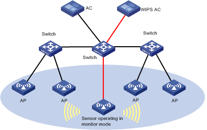
Operating in an existing WLAN
You can deploy WIPS in an existing WLAN by enabling WIPS on the ACs and APs in the WLAN, and configure the sensors to operate in monitor mode or in hybrid mode, as shown in Figure 67.
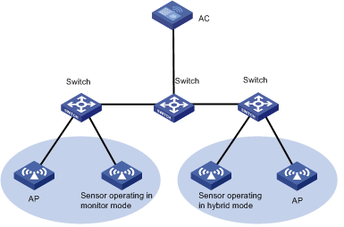
Basic WIPS configurations
Accessing the WIPS Management page
The WIPS Management page provides access to basic WIPS configurations.
To access the WIPS Management page:
1. Click the Service tab.
2. From the navigation tree, select WLAN Manager > WIPS Management > WIPS Configuration.
The WIPS Management page displays all functions.
3. Select an AC that you want to configure.
The WIPS Management page displays information about the AC.
Enabling WIPS
By default, WIPS is disabled on an AC.
To enable WIPS:
1. Access the WIPS Management page.
2. Select the target AC from the AC list.
3. Select Enable WIPS.
4. Click OK.
|
|
NOTE: You cannot enable WIDS and WIPS on an AC at the same time, and you cannot disable WIDS on a Comware-based AC that has WIDS configured. To enable WIPS on an AC where WIDS is already enabled, first delete all WIDS configurations and set all AP templates to operate in normal mode. |
Configuring time parameters
1. Access the WIPS Management page.
2. Click the Time Parameters tab.
3. Configure the following time parameters for the AC:
¡ Time in seconds for the AP to change to inactive status—Specify the time to wait before WIPS switches the AP to inactive state. When WIPS detects that a fit AP does not send any packet within the specified time, it switches the state of the AP from active to inactive. The valid time range is 60 to 600 seconds, and the default is 300 seconds.
¡ Time in seconds for the client to change to inactive status—Specify the time to wait before WIPS switches the client to inactive state. When WIPS detects that a client does not send any packet within the specified time, it switches the state of the client from active to inactive. The valid time range is 120 to 1200 seconds, and the default is 600 seconds.
¡ Aging time in seconds for inactive devices—Specify the aging timer for an inactive wireless device. When WIPS detects that a wireless device does not send any packet within the specified time, it removes the wireless device. The valid time range is 60 to 2592000 seconds, and the default is 86400 seconds.
¡ Re-categorization period (s)—Specify the time interval at which WIPS re-categorizes detected APs. The valid time range is 10 to 36000 seconds, and the default is 600 seconds.
¡ Traffic statistics periods (s)—Specify the interval at which APs sends collected traffic data to the AC. The valid time range is 60 to 86400 seconds, and the default is 900 seconds.
¡ Dynamic Trust List Aging Time (s)—Specify the aging time for the wireless devices in the dynamic trust list, in the range of 60 to 3600 seconds. The default is 60 seconds. When the aging time of a device in the list expires, WIPS removes the device from the list if it cannot detect the device any more. This parameter only takes effect on the dynamic trust list.
¡ Device Status Update Interval (s)—Set the information update interval for wireless devices. When this interval is set, a sensor notifies the AC of the current state of the wireless devices at the specified interval when their information does not change so that the AC can get the wireless device status in time.
4. Click OK.
Configuring the permitted channel list
You can configure a permitted channel list in a WLAN. WIPS generates alarms when detecting packet transmission on any channel not in the permitted channel list.
To configure the permitted channel list:
1. Access the WIPS Management page.
2. Click the Permitted Channel List tab.
The permitted channel list displays all channels supported by 802.11. Some channels are grayed out when you select different ACs because they support different country codes.
3. Select the channels to add to the permitted channel list. To add all supported channels to the permitted channel list, select Select All.
4. Click OK.
Configuring the static-trusted address list
The static-trusted address list contains MAC addresses of all manually configured trusted devices.
Viewing the static-trusted address list
1. Access the WIPS Management page.
2. Click the Static Trusted Address List tab.
The static-trusted address list displays all manually configured trusted MAC addresses.
¡ MAC Address—MAC address of the device.
¡ Vendor—Vendor of the device or NIC. IMC uses the MAC address to identify the vendor of the device or NIC. If the MAC address is not an OUI MAC address or a legal MAC address, the field displays Unknown.
¡ Delete—Allows you to delete the MAC address.
If the static-trusted address list contains enough entries, the following navigational aids are displayed:
¡ Click
the Next Page icon ![]() to page forward in the static-trusted address list.
to page forward in the static-trusted address list.
¡ Click
the Last Page icon ![]() to page forward to the end of the static-trusted address list.
to page forward to the end of the static-trusted address list.
¡ Click
the Previous Page icon ![]() to page backward in the static-trusted address list.
to page backward in the static-trusted address list.
¡ Click
the First Page icon ![]() to page backward to the front of the static-trusted address list.
to page backward to the front of the static-trusted address list.
Click 8, 15, 50, 100, or 200 at the upper right of the static-trusted address list to specify the number of items you want to display on each page.
|
|
NOTE: You can sort the static-trusted address list by the MAC Address and Vendor fields. Click the column label to sort the list by the selected field. The column label allows you to toggle between the sort options specific to each field. |
Synchronizing the static-trusted address list
IMC supports synchronizing the static-trusted address list automatically or manually. By default, IMC automatically synchronizes the static-trusted address list every 2 hours.
To manually synchronize the static-trusted address list:
1. Access the WIPS Management page.
2. Click the Static Trusted Address List tab.
3. Click Synchronize to start synchronizing the static-trusted address list.
The page is refreshed to display the most recent data after the synchronization process is completed.
Querying the static-trusted MAC addresses
1. Access the WIPS Management page.
2. Click the Static Trusted Address List tab.
3. In the query field, enter a partial or complete MAC address in the xx:xx:xx:xx:xx:xx format.
4. Click the Query
icon ![]() .
.
The static-trusted address list displays all matching static-trusted MAC addresses.
5. Click Reset to clear the query criteria and display all static-trusted MAC addresses.
Adding a trusted MAC address
1. Access the WIPS Management page.
2. Click the Static Trusted Address List tab.
3. Click Add.
The Add MAC Address dialog box opens.
4. Enter the MAC address you want to add, in the xx:xx:xx:xx:xx:xx format.
5. Click OK.
Importing trusted MAC addresses
WIPS supports importing MAC addresses to the static-trusted address list in batches. Only .csv files are supported. The files can contain only MAC addresses, and do not require any row heading or line heading.
To import trusted MAC addresses:
1. Access the WIPS Management page.
2. Click the Static Trusted Address List tab.
3. Click Import.
The Select File page opens.
4. Click Browse or the field to select a file.
5. Click Next.
The Import MAC Address Information page opens, displaying the following information:
¡ MAC Address—MAC address of the device.
¡ Vendor—Vendor of the device or NIC. IMC uses the MAC address to identify the vendor of the device or NIC. If the MAC address is not an OUI MAC address or a legal MAC address, the field displays Unknown.
If you do not want to import certain MAC addresses, select them and click Delete.
6. Click OK.
The Imported MAC Address Result page opens, displaying the result for importing MAC address information.
7. Click OK to return to the Static Trusted Address List page.
Deleting static-trusted MAC addresses
1. Access the WIPS Management page.
2. Click the Static Trusted Address List tab.
3. Delete a single MAC address or delete multiple MAC addresses in batches:
¡ Select the MAC addresses you want to delete, and click Delete.
¡ Click
the Delete icon ![]() for the MAC address you want to delete.
for the MAC address you want to delete.
4. In the confirmation dialog box, click OK.
Configuring the alarm-ignored address list
The alarm-ignored address list contains the MAC addresses of all manually configured APs or clients. For wireless devices in the alarm-ignored address list, WIPS only monitors them and does not generate any alarms for their actions.
Viewing the alarm-ignored address list
1. Access the WIPS Management page.
2. Click the Alarm-Ignored Address List tab.
The alarm-ignored address list displays MAC addresses of all devices for whose actions WIPS does not generate alarms.
¡ MAC Address—MAC address of the device.
¡ Vendor—Vendor of the device or NIC. IMC uses the MAC address to identify the vendor of the device or NIC. If the MAC address is not an OUI MAC address or a legal MAC address, the field displays Unknown.
¡ Delete—Allows you to delete the MAC address.
If the alarm-ignored address list contains enough entries, the following navigational aids are displayed:
¡ Click
the Next Page icon ![]() to page forward in the alarm-ignored address list.
to page forward in the alarm-ignored address list.
¡ Click
the Last Page icon ![]() to page forward to the end of the alarm-ignored address list.
to page forward to the end of the alarm-ignored address list.
¡ Click
the Previous Page icon ![]() to page backward in the alarm-ignored address list.
to page backward in the alarm-ignored address list.
¡ Click
the First Page icon ![]() to page backward to the front of the alarm-ignored address list.
to page backward to the front of the alarm-ignored address list.
Click 8, 15, 50, 100, or 200 at the upper right of the alarm-ignored address list to specify the number of items you want to display on each page.
|
|
NOTE: You can sort the alarm-ignored address list by the MAC Address and Vendor fields. Click the column label to sort the list by the selected field. The column label allows you to toggle between the sort options specific to each field. |
Synchronizing the alarm-ignored address list
IMC supports synchronizing the alarm-ignored address list automatically or manually. By default, IMC automatically synchronizes the alarm-ignored address list every 2 hours.
To manually synchronize the alarm-ignored address list:
1. Access the WIPS Management page.
2. Click the Alarm-Ignored Address List tab.
3. Click Synchronize to start synchronizing the alarm-ignored address list.
The page is refreshed to display the most recent data after the synchronization process is completed.
Querying the alarm-ignored address list
1. Access the WIPS Management page.
2. Click the Alarm-Ignored Address List tab.
3. Enter a partial or complete MAC address in the xx:xx:xx:xx:xx:xx format.
4. Click Query.
The alarm-ignored address list displays all matching alarm-ignored MAC addresses.
5. Click Reset to clear the query criteria and display all alarm-ignored MAC addresses.
Adding an alarm-ignored MAC address
1. Access the WIPS Management page.
2. Click the Alarm-Ignored Address List tab.
3. Click Add.
The Add MAC Address window opens.
4. Enter the MAC address you want to add, in the xx:xx:xx:xx:xx:xx format.
5. Click OK.
Importing alarm-ignored MAC addresses
WIPS supports importing MAC addresses to the alarm-ignored address list in batches. Only .csv files are supported. The files can contain only MAC addresses, and do not require any row heading or line heading.
To import alarm-ignored MAC addresses:
1. Access the WIPS Management page.
2. Click the Alarm-Ignored Address List tab.
3. Click Import.
The Select File page opens.
4. Click Browse or the field to select a file.
5. Click Next.
The Import MAC Address Information page opens, displaying the following information:
¡ MAC Address—MAC address of the device.
¡ Vendor—Vendor of the device or NIC. IMC uses the MAC address to identify the vendor of the device or NIC. If the MAC address is not an OUI MAC address or a legal MAC address, the field displays Unknown.
If you do not want to import certain MAC addresses, select them and click Delete.
6. Click OK.
The Imported MAC Address Result page opens, displaying the result for importing MAC address information.
7. Click OK.
Deleting alarm-ignored MAC addresses
This function enables you to delete one or more MAC addresses from the alarm-ignored address list.
To delete alarm-ignored MAC addresses:
1. Access the WIPS Management page.
2. Click the Alarm-Ignored Address List tab.
3. Delete a single MAC address or multiple MAC addresses in batches:
¡ Select the MAC addresses you want to delete, and click Delete.
¡ Click
the Delete icon ![]() for the MAC address you want to delete.
for the MAC address you want to delete.
4. In the confirmation dialog box, click OK.
Configuring the static-blocked address list
The static-blocked address list contains the MAC addresses of all manually configured rogue devices.
Viewing the static-blocked address list
1. Access the WIPS Management page.
2. Click the Static Blocked Address List tab.
The static-blocked address list displays all blocked MAC addresses.
Static Blocked Address List
¡ MAC Address—MAC address of the device.
¡ Vendor—Vendor of the device or NIC. IMC uses the MAC address to identify the vendor of the device or NIC. If the MAC address is not an OUI MAC address or a legal MAC address, the field displays Unknown.
¡ Delete—Allows you to delete the MAC address.
If the static-blocked address list contains enough entries, the following navigational aids are displayed:
· Click the Next Page
icon ![]() to page
forward in the static-blocked address list.
to page
forward in the static-blocked address list.
· Click the Last Page
icon ![]() to page
forward to the end of the static-blocked address list.
to page
forward to the end of the static-blocked address list.
· Click the Previous Page
icon ![]() to page
backward in the static-blocked address list.
to page
backward in the static-blocked address list.
· Click the First Page
icon ![]() to page
backward to the front of the static-blocked address list.
to page
backward to the front of the static-blocked address list.
Click 8, 15, 50, 100, or 200 at the upper right of the static-blocked address list to specify the number of items you want to display on each page.
|
|
NOTE: You can sort the static-blocked address list by the MAC Address and Vendor fields. Click the column label to sort the list by the selected field. The column label allows you to toggle between the sort options specific to each field. |
Synchronizing the static-blocked address list
IMC supports synchronizing the static-blocked address list automatically or manually. By default, IMC automatically synchronizes the static-blocked address list every 2 hours.
To manually synchronize the static-blocked address list:
1. Access the WIPS Management page.
2. Click the Static Blocked Address List tab.
3. Click Synchronize to start synchronizing the static-blocked address list.
The page is refreshed to display the most recent data after the synchronization process is completed.
Querying static-blocked addresses
1. Access the WIPS Management page.
2. Click the Static Blocked Address List tab.
3. Enter a partial or complete MAC address in the xx:xx:xx:xx:xx:xx format.
4. Click Query.
The static-blocked address list displays all matching static-blocked MAC addresses.
5. Click Reset to clear the query criteria and display all static-blocked MAC addresses.
Adding a static-blocked MAC address
1. Access the WIPS Management page.
2. Click the Static Blocked Address List tab.
3. Click Add.
The Add MAC Address window opens.
4. Enter the MAC address you want to add, in the xx:xx:xx:xx:xx:xx format.
Importing static-blocked MAC addresses
WIPS supports importing MAC addresses to the static-blocked address list in batches. Only .csv files are supported. The files can contain only MAC addresses, and do not require any row heading or line heading.
To import static-blocked MAC addresses:
1. Access the WIPS Management page.
2. Click the Static Blocked Address List tab.
3. Click Import.
The Select File page opens.
4. Click Browse to select a file, or enter the URL or the file to be imported.
5. Click Next.
The Import MAC Address Information page opens, displaying the following information:
¡ MAC Address—MAC address of the device.
¡ Vendor—Vendor of the device or NIC. IMC uses the MAC address to identify the vendor of the device or NIC. If the MAC address is not an OUI MAC address or a legal MAC address, the field displays Unknown.
If you do not want to import specific MAC addresses, select them and click Delete.
6. Click OK.
The Imported MAC Address Result page opens, displaying the result for importing MAC address information.
7. Click OK.
Deleting static-blocked MAC addresses
This function allows you to delete one or more devices from the static-blocked address list.
To delete static-blocked MAC addresses:
1. Access the WIPS Management page.
2. Click the Static Blocked Address List tab.
3. Delete a single MAC address or delete multiple MAC addresses in batches:
¡ Select the MAC addresses you want to delete, and click Delete.
¡ Click
the Delete icon ![]() for the MAC address you want to delete.
for the MAC address you want to delete.
4. In the confirmation dialog box, click OK.
Permitting blocked clients to access the WLAN
By default, WIPS prohibits the clients in the static-blocked address list from accessing the WLAN. You can configure WIPS to permit blocked clients to access the WLAN.
To permit blocked clients to access the WLAN:
1. Access the WIPS Management page.
2. Click the Static Blocked Address List tab.
3. Select Permit Blocked Device.
4. Click OK.
Configuring the static countermeasures address list
The static countermeasures address list contains the MAC addresses of all manually configured rogue devices. WIPS takes countermeasures against rogue devices in the list by using the following methods:
· Controlling authorized APs to prevent rogue clients.
· Enabling sensors to send 802.11 frames to disassociate rogue wireless devices.
Viewing the static countermeasures address list
1. Access the WIPS Management page.
2. Click the Static Countermeasures Address List tab.
The static countermeasures address list displays MAC addresses of all devices where countermeasures are taken.
¡ MAC Address—MAC address of the device.
¡ Vendor—Vendor of the device or NIC. IMC uses the MAC address to identify the vendor of the device or NIC. If the MAC address is not an OUI MAC address or a legal MAC address, the field displays Unknown.
¡ Delete—Allows you to delete the MAC address.
If the static countermeasures address list contains enough entries, the following navigational aids are displayed:
· Click the Next Page
icon ![]() to page
forward in the static countermeasures address list.
to page
forward in the static countermeasures address list.
· Click the Last Page
icon ![]() to page
forward to the end of the static countermeasures address list.
to page
forward to the end of the static countermeasures address list.
· Click the Previous Page
icon ![]() to page
backward in the static countermeasures address list.
to page
backward in the static countermeasures address list.
· Click the First Page
icon ![]() to page
backward to the front of the static countermeasures address list.
to page
backward to the front of the static countermeasures address list.
Click 8, 15, 50, 100, or 200 at the upper right of the static countermeasures address list to specify the number of items you want to display on each page.
|
|
NOTE: You can sort the static countermeasures address list by the MAC Address and Vendor fields. Click the column label to sort the list by the selected field. The column label allows you to toggle between the sort options specific to each field. |
Synchronizing the static countermeasures address list
IMC supports synchronizing the static countermeasures address list automatically or manually. By default, IMC automatically synchronizes the static countermeasures address list every 2 hours
To manually synchronize the static countermeasures address list:
1. Access the WIPS Management page.
2. Click the Static Countermeasures Address List tab.
3. Click Synchronize to start synchronizing the static countermeasures address list.
The page is refreshed to display the most recent data after the synchronization process is completed.
Querying static countermeasures MAC addresses
1. Access the WIPS Management page.
2. Click the Static Countermeasures Address List tab.
3. Enter a partial or complete MAC address in the xx:xx:xx:xx:xx:xx format.
4. Click Query.
The static countermeasures address list displays all matching MAC addresses.
5. Click Reset to clear the query criteria and display all static countermeasures MAC addresses.
Adding a static countermeasures MAC address
1. Access the WIPS Management page.
2. Click the Static Countermeasures Address List tab.
3. Click Add.
The Add MAC Address window opens.
4. Enter the MAC address you want to add, in the xx:xx:xx:xx:xx:xx format.
5. Click OK.
Importing static countermeasures MAC addresses
WIPS supports importing MAC addresses to the static countermeasures address list in batches. Only .csv files are supported. The files can contain only MAC addresses, and do not require any row heading or line heading
To import static countermeasures MAC addresses:
1. Access the WIPS Management page.
2. Click the Static Countermeasures Address List tab.
3. Click Import.
The Select File page opens.
4. Click Browse to select a file, or enter the URL or the file to be imported.
5. Click Next.
The Import MAC Address Information page opens, displaying the following information:
¡ MAC Address—MAC address of the device.
¡ Vendor—Vendor of the device or NIC. IMC uses the MAC address to identify the vendor of the device or NIC. If the MAC address is not an OUI MAC address or a legal MAC address, the field displays Unknown.
If you do not want to import certain MAC addresses, select them and click Delete.
6. Click OK.
The Imported MAC Address Result page opens, displaying the result for importing MAC address information.
7. Click OK.
Deleting static countermeasures MAC addresses
1. Access the WIPS Management page.
2. Click the Static Countermeasures Address List tab.
3. Delete a single MAC address or multiple MAC addresses in batches:
¡ Select the MAC addresses you want to delete, and click Delete.
¡ Click
the Delete icon ![]() for the MAC address you want to delete.
for the MAC address you want to delete.
4. In the confirmation dialog box, click OK.
Configuring the static-trusted OUI list
All MAC addresses in the static-trusted OUI list are considered as trusted MAC addresses.
Viewing the static-trusted OUI list
1. Access the WIPS Management page.
2. Click the Static Trusted OUI List tab.
The static-trusted OUI list displays all trusted OUIs.
¡ OUI—OUI, in the xx:xx:xx format.
¡ Vendor—Vendor to which the OUI belongs.
¡ Delete—Allows you to delete the OUI.
If the static-trusted OUI list contains enough entries, the following navigational aids are displayed:
· Click the Next Page
icon ![]() to page
forward in the static-trusted OUI list.
to page
forward in the static-trusted OUI list.
· Click the Last Page
icon ![]() to page
forward to the end of the static-trusted OUI list.
to page
forward to the end of the static-trusted OUI list.
· Click the Previous Page
icon ![]() to page
backward in the static-trusted OUI list.
to page
backward in the static-trusted OUI list.
· Click the First Page
icon ![]() to page
backward to the front of the static-trusted OUI list.
to page
backward to the front of the static-trusted OUI list.
Click 8, 15, 50, 100, or 200 at the upper right of the static-trusted OUI list to specify the number of items you want to display on each page.
|
|
NOTE: You can sort the static-trusted OUI list by the OUI and Vendor fields. Click the column label to sort the list by the selected field. The column label allows you to toggle between the sort options specific to each field. |
Synchronizing the static-trusted OUI list
IMC supports synchronizing the static-trusted OUI list automatically or manually. By default, IMC automatically synchronizes the static-trusted OUI list every 2 hours
To manually synchronize the static-trusted OUI list:
1. Access the WIPS Management page.
2. Click the Static Trusted OUI List tab.
3. Click Synchronize to start synchronizing the static-trusted OUI list.
The page is refreshed to display the most recent data after the synchronization process is completed.
Querying OUIs
1. Access the WIPS Management page.
2. Click the Static Trusted OUI List tab.
3. Enter a partial or complete OUI in the query field on the top right corner, in the xx:xx:xx format.
4. Click the Query
icon ![]() . The
OUI list displays all OUIs matching the query criteria.
. The
OUI list displays all OUIs matching the query criteria.
5. Clear the Query
field, and click the Query icon ![]() to display all OUIs.
to display all OUIs.
Adding an OUI
You can add OUIs one by one to the static-trusted OUI list or select OUIs from WSM.
To manually add an OUI:
1. Access the WIPS Management page.
2. Click the Static Trusted OUI List tab.
3. Click Add. The Add an OUI dialog box opens.
4. Enter a complete OUI, in the xx:xx:xx format.
5. Click OK.
To select OUIs from WSM:
1. Access the WIPS Management page.
2. Click the Static Trusted OUI List tab.
3. Click Select. The dialog box for selecting OUIs opens.
4. Query OUIs:
a. Set the query criteria in the Query area.
- OUI—Enter a partial or complete OUI, in the xx:xx:xx format.
- Vendor Name—Enter a partial or complete vendor name.
b. Click the Query
icon ![]() . The
OUI list displays all OUIs matching the query criteria.
. The
OUI list displays all OUIs matching the query criteria.
c. Clear the Query
field, and click the Query icon ![]() to display all OUIs.
to display all OUIs.
d. Click Reset to clear the query criteria and display all OUIs.
5. Select one or more OUIs from the OUI List.
6. Click OK.
Deleting OUIs
After you delete an OUI from the static-trusted OUI list, WIPS re-classifies the related devices after the reclassification time is reached.
To delete OUIs:
1. Access the WIPS Management page.
2. Click the Static Trusted OUI List tab.
3. Click the Delete
icon ![]() for the
target OUI to delete one OUI, or select multiple OUIs and then click Delete to delete them in batches.
for the
target OUI to delete one OUI, or select multiple OUIs and then click Delete to delete them in batches.
4. In the confirmation dialog box, click OK.
Configuring the function set
1. Access the WIPS Management page.
2. Click the Function Set tab.
3. Configure the function set as needed:
¡ Enable ADOS—ADOS prevents WIPS from being attacked. When this function is enabled, WIPS detects attacks to itself and takes countermeasures such as packet rate limit and filtering.
¡ Enable WIPS for a hybrid sensor that provides access services—This function improves WIPS detection and attack prevention performance, but decreases access performance of the sensor.
¡ Function set supported by the attack detection policy—Options are Ad Hoc Network, Spoofing AP, Spoofing Client, AP Flood Attack, EAPOL-Start DoS Attack, Authentication DoS Attack, Association DoS Attack, Reassociation DoS Attack, Weak IV, and Invalid OUI.
¡ Function set supported by the countermeasures policy—Options are Misconfigured AP, Rogue AP, Unauthorized Client, External AP, Misassociated Client, Potential-rogue AP, Potential-external AP, Uncategorized AP, Uncategorized Client, and Potential-authorized AP.
4. Click OK.
|
|
NOTE: After you configure the function set supported by the attack detection policy, you can only select the configured function set when you configure the attack detection policy. The rule also takes effect on the function set supported by the countermeasures policy. |
Configuring sensors
Viewing the sensor list
1. Click the Service tab.
2. From the navigation tree, select WLAN Manager > WIPS Management > Sensor Management.
The sensor list displays all sensors.
¡ Status—Online status of the sensor: ![]() Online and
Online and ![]() Offline.
Offline.
¡ AP Label—Label of the sensor. Click the label of the sensor to view its details.
¡ Radio 1—Management status and
detection mode of the radio. The Down icon ![]() indicates that
the radio is in down management status, and the Up
icon
indicates that
the radio is in down management status, and the Up
icon ![]() indicates
that the radio is in up management status.
indicates
that the radio is in up management status.
The following detection modes are available:
- Access First—Gives priority to access services. The access duration is longer than the WIPS duration.
- Detection First—Gives priority to WIPS. The WIPS duration is longer than the access duration.
- Hybrid Mode—Balanced between the access first and detection first operating mode.
- Detection Only—Provides WIPS service and does not provide access services.
To modify the operating mode of a radio,
click the Modify icon ![]() .
.
If WIPS is not enabled on the radio, or the sensor does not have Radio 1, the field displays two consecutive hyphens (--).
¡ Radio 2—If WIPS is not enabled on the radio, or the sensor does not have Radio 2, the field displays two consecutive hyphens (--).
Description for the management status and detection mode of Radio 2 is the same as Radio 1.
¡ Radio 3—If WIPS is not enabled on the radio, or the sensor does not have Radio 3, the field displays two consecutive hyphens (--).
Description for the management status and detection mode of Radio 3 is the same as Radio 1.
¡ Virtual Security Domain—Name of the virtual security domain to which the sensor is bound.
¡ AC—Label of the AC with which the sensor is associated. Click the label of the AC to view its details.
¡ Operation—Click the Operation icon ![]() for the sensor to display the operation menu.
for the sensor to display the operation menu.
The operational tasks provided in the menu list include deleting the sensor and the virtual security domain to which the sensor is bound.
If the sensor list contains enough entries, the following navigational aids are displayed:
· Click the Next Page
icon ![]() to page
forward in the sensor list.
to page
forward in the sensor list.
· Click the Last Page
icon ![]() to page
forward to the end of the sensor list.
to page
forward to the end of the sensor list.
· Click the Previous Page
icon ![]() to page
backward in the sensor list.
to page
backward in the sensor list.
· Click the First Page
icon ![]() to page
backward to the front of the sensor list.
to page
backward to the front of the sensor list.
Click 8, 15, 50, 100, or 200 at the upper right of the sensor list to specify the number of items you want to display on each page.
|
|
NOTE: You can sort the sensor list by all fields except the Operation field. Click the column label to sort the list by the selected field. The column label allows you to toggle between the sort options specific to each field. |
Synchronizing the sensor list
IMC supports synchronizing the sensor list automatically or manually. By default, IMC automatically synchronizes the sensor list every 2 hours.
To manually synchronize the sensor list:
1. Click the Service tab.
2. From the navigation tree, select WLAN Manager > WIPS Management > Sensor Management.
The sensor list displays all sensors.
3. Click Synchronize to start synchronizing the sensor list.
The page is refreshed to display the most recent data after the synchronization process is completed.
Querying sensors
WSM provides basic query and advanced query. Basic query criteria include several key parameters for quick searches. Advanced query offers various query criteria for precise matching.
To query sensors:
1. Click the Service tab.
2. From the navigation tree, select WLAN Manager > WIPS Management > Sensor Management.
The sensor list displays all sensors.
3. Perform a basic query:
a. Enter the name of the virtual security domain. WSM supports fuzzy matching for this field.
b. Click the Query icon
![]() . The
sensor list displays all sensors matching the query criteria.
. The
sensor list displays all sensors matching the query criteria.
4. Clear the Query
box, and click the Query icon ![]() to display all sensors.
to display all sensors.
5. Perform an advanced query:
a. Click the Expand
icon ![]() next to the Query field to expand the Query area. Click it again to hide the Query area.
next to the Query field to expand the Query area. Click it again to hide the Query area.
b. Enter or select one or more of the following query criteria:
- AP Label—Enter a partial or complete AP label. WSM supports fuzzy matching for this field.
- Virtual Security Domain—Enter a partial or complete virtual security domain name to display all sensors that are bound to the domain. WSM supports fuzzy matching for this field.
- Status—Select the online status of the sensor. Options are All, Online, and Offline.
- Detection Mode—Select the detection mode of the radio. Options are All, Access First, Detection First, Hybrid Mode, and Detection Only.
- AC—Select the AC with which the sensor associates.
c. Click Query.
The sensor list displays all matching sensors.
d. Click Reset to clear the query criteria and display all sensors.
Adding a sensor
This function enables you to add a sensor and to specify the detection mode for radios.
To add sensors:
1. Click the Service tab.
2. From the navigation tree, select WLAN Manager > WIPS Management > Sensor Management.
The sensor list displays all sensors.
3. Click Add.
The Add Sensor page opens.
4. Select a detection mode for the radios from the Detection Mode list. Options are Access First, Detection First, Hybrid Mode, and Detection Only.
For more information about the detection modes, see "Viewing the sensor list."
5. Click Select below the radio list and select radios from the Add Sensor page by using the following process:
a. Enter a partial or complete AP label in the Query field, and click the query icon ![]() .
.
Or,
Select or enter one or more of the following query criteria:
- Radio ID—Select the radio ID. Options are All, Radio 1, Radio 2, and Radio 3.
- Radio Type—Select the radio type. Options are All, 802.11a, 802.11b, 802.11g, 802.11gn, and 802.11an.
- AP Label—Enter the label of the fit AP to which the radios belong. WSM supports fuzzy matching for this field.
- AC—Select the AC.
b. Click Query.
The Radio List displays all matching radios.
c. Select one or more radios.
d. Click OK to return to the Add Sensor page.
6. Click OK.
Binding sensors to a virtual security domain
By default, sensors are bound to the virtual security domain named Default. You can bind sensors to another virtual security domain. You can bind a sensor to only one virtual security domain.
To bind sensors to a virtual security domain:
1. Click the Service tab.
2. From the navigation tree, select WLAN Manager > WIPS Management > Sensor Management.
The Sensor List displays all sensors.
3. Bind multiple sensors to a virtual security domain or bind a sensor to a virtual security domain:
¡ Select the sensors you want to bind to a virtual security domain, and click Bind.
The Bind to Virtual Security Domain window opens.
¡ Click
the Operation icon ![]() for the sensor you want to bind to a virtual security domain.
for the sensor you want to bind to a virtual security domain.
The Bind to Virtual Security Domain window opens.
4. Select a virtual security domain from the virtual security domain list.
Virtual Security Domain List contents:
¡ Name—Name of the virtual security domain.
¡ AP Categorization Rule—Name of the AP categorization rule added to the virtual security domain.
5. Click OK.
Deleting sensors
Deleting a sensor disables WIPS for all radios on the sensor.
To delete sensors:
1. Click the Service tab.
2. From the navigation tree, select WLAN Manager > WIPS Management > Sensor Management.
The sensor list displays all sensors.
3. Delete a single sensor or multiple sensors in batches:
¡ Select the sensors you want to delete, and click Delete.
¡ Click
the Operation icon ![]() for the sensor you want to delete, and select Delete
from the shortcut menu.
for the sensor you want to delete, and select Delete
from the shortcut menu.
4. In the confirmation dialog box, click OK.
Managing virtual security domains
Configuring AP categorization rules
WIPS classifies detected APs or specifies the threat levels for detected APs according to AP categorization rules. You can view the types or threat levels of all detected APs on the APs Detected page.
WIPS uses AP categorization rules to classify detected APs into the following types:
· Authorized AP—APs permitted in the WLAN.
· External AP—APs in adjacent wireless networks. For example, APs in the WLAN of a nearby cafe.
· Misconfigured AP—APs that can be used in a wireless network but with wrong configurations. For example, an AP in the permitted device list but with a wrong SSID.
· Rogue AP—APs that cannot be used in a wireless network.
· None—APs whose category cannot be determined.
An AP categorization rule can include one or more of the following subrules:
· SSID—Matches SSIDs.
· Data Security—Matches security methods used by the AP.
· Authentication method—Matches authentication methods used by the AP.
· RSSI—Matches RSSIs of APs.
· Running time of the AP—Matches running duration of APs.
· Number of associated clients—Matches number of associated clients of APs.
· Number of APs detected by the sensor—Matches number of APs detected by the sensor.
· Vendor—Matches OUIs or vendor names of APs.
AP threat levels indicate the impact of potential-authorized APs, potential-rogue APs, potential-external APs, or unrecognized APs to the WLAN. A higher threat level indicates more serious impact to the WLAN. You can specify a threat level for APs matching an AP categorization rule, in the range of 0 to 100.
If multiple AP categorization rules exist, you can specify their precedence. WIPS matches the rules in the order of their precedence. When a match is found, WIPS takes actions according to the following criteria:
· If you have configured the AP type in the rule, WIPS assigns the detected AP to the AP type and does not match the detected AP against the next AP categorization rule.
· If you have not configured the AP type in the rule, WIPS assigns a threat level to the detected AP and matches the detected AP against the next AP categorization rule.
Viewing the AP categorization rule list
1. Click the Service tab.
2. From the navigation tree, select WLAN Manager > WIPS Management > Virtual Security Domain.
3. Click the AP Categorization Rule tab.
The AP categorization rule list displays all AP categorization rules.
AP Categorization Rule list contents
¡ Name—Name of the AP categorization rule. Click the name of the AP categorization rule to view its details.
¡ Category—Type of the APs matching the AP categorization rule.
¡ Threat Level—Threat level of the APs matching the AP categorization rule. WIPS assigns the threat level to the detected AP only when the Category field displays None.
¡ AC—Label of the AC where the AP categorization rule is configured. Click the label of the AC to view its details.
¡ Operation—Click the Operation icon ![]() for the AP categorization rule to display the operation menu.
for the AP categorization rule to display the operation menu.
The operational tasks provided in the menu include modifying the AP categorization rule and viewing the virtual security domain to which the AP categorization rule is bound.
If the AP categorization rule list contains enough entries, the following navigational aids are displayed:
· Click the Next Page
icon ![]() to page forward
in the AP categorization rule list.
to page forward
in the AP categorization rule list.
· Click the Last Page
icon ![]() to page
forward to the end of the AP categorization rule list.
to page
forward to the end of the AP categorization rule list.
· Click the Previous Page
icon ![]() to page
backward in the AP categorization rule list.
to page
backward in the AP categorization rule list.
· Click the First Page
icon ![]() to page
backward to the front of the AP categorization rule list.
to page
backward to the front of the AP categorization rule list.
Click 8, 15, 50, 100, or 200 at the upper right of the AP categorization rule list to specify the number of items you want to display on each page.
|
|
NOTE: You can sort the AP categorization rule list by all fields except the Operation field. Click the column label to sort the list by the selected field. The column label allows you to toggle between the sort options specific to each field. |
Synchronizing the AP categorization rule list
IMC supports synchronizing the AP categorization rule list automatically or manually. By default, IMC automatically synchronizes the AP categorization rule list every 2 hours.
To manually synchronize the AP categorization rule list:
1. Click the Service tab.
2. From the navigation tree, select WLAN Manager > WIPS Management > Virtual Security Domain.
3. Click the AP Categorization Rule tab.
The AP categorization rule list displays all AP categorization rules.
4. Click Synchronize to start synchronizing the AP categorization rule list.
The page is refreshed to display the most recent data after the synchronization process is completed.
Querying AP categorization rules
To perform a basic query:
1. Click the Service tab.
2. From the navigation tree, select WLAN Manager > WIPS Management > Virtual Security Domain.
3. Click the AP Categorization Rule tab.
The AP categorization rule list displays all AP categorization rules.
4. Enter a partial or complete name of the AP categorization rule in the query field on the upper right corner.
5. Click the Query icon
![]() . The AP
categorization list displays all AP categorization rules matching the query
criteria.
. The AP
categorization list displays all AP categorization rules matching the query
criteria.
6. Clear the Query
field, and click the Query icon ![]() to display all AP
categorization rules.
to display all AP
categorization rules.
To perform an advanced query:
1. Click the Service tab.
2. From the navigation tree, select WLAN Manager > WIPS Management > Virtual Security Domain.
3. Click the AP Categorization Rule tab.
The AP categorization rule list displays all AP categorization rules.
4. Click the Expand
icon ![]() to the right of the query field.
to the right of the query field.
5. Enter or select one or more of the following query criteria:
¡ Name—Enter the name of the AP categorization rule. WSM supports fuzzy matching for this field.
¡ AC—Select the AC where the AP categorization rule is configured.
6. Click Query.
The AP categorization rule list displays all matching AP categorization rules.
7. Click Reset to clear the query criteria and display all AP categorization rules.
Adding an AP categorization rule
1. Click the Service tab.
2. From the navigation tree, select WLAN Manager > WIPS Management > Virtual Security Domain.
3. Click the AP Categorization Rule tab.
The AP categorization rule list displays all AP categorization rules.
4. Click Add.
The Add AP Categorization Rule page opens.
5. Configure the following basic parameters for the AP categorization rule:
¡ Name—Enter the name of the AP categorization rule, a string of 1 to 32 characters. Valid characters include integers, letters, and underscores (_).
¡ AC—Select the AC on which you want to create the AP categorization rule.
¡ Category—Select the type for the APs matching the AP categorization rule. Options are None, Authorized, External, Misconfigured, and Rogue.
¡ Threat Level—Enter the threat level. The valid value is in the range of 1 to 100. WIPS assigns a threat level to the detected AP when you select None for the Category field.
¡ Sub-Rule Match Criteria—Select the subrule match criteria:
¡ AND—An AP that matches all subrules matches the AP categorization rule.
¡ OR—An AP that matches one of the subrules matches the AP categorization rule.
¡ Sub rules—Select the subrules you want to enable. The parameters of the selected subrules are displayed. Subrules include Authentication Method, Data Security, SSID, RSSI, Operation Time, Client Count, Detect AP Count, and Device Vendor.
6. Select the authentication method to match APs from the Authentication Method list.
a. Select the Match Criteria. The option is Include.
b. Select the authentication method. Options are None, PSK, 802.1X, and Others.
7. Configure the security method to match APs:
a. Select the Match Criteria. Options are Include and Equal to.
- Include—Matches security methods that include the specified security method.
- Equal to—Matches security methods that are the same as the specified security method.
b. Select the security method. Options are Clear, WEP, WPA, and WPA2.
8. Configure the SSID to match APs:
a. Select the Match Criteria. Options are Include, Exclude, Equal to, and Not Equal to.
- Include—Matches SSIDs that include the specified SSID string.
- Exclude—Matches SSIDs that do not include the specified SSID string.
- Equal to—Matches SSIDs that are the same as the specified SSID string.
- Not Equal to—Matches SSIDs that are different from the specified SSID string.
b. Enter an SSID string.
c. Select Yes or No from the Case Sensitive list.
9. Configure the RSSI to match APs:
a. Select the Match Criteria. Options are Greater than, Smaller than, and Between.
b. Start Value—Enter an RSSI, in the range of 0 to 89.
c. End Value—Enter an RSSI, which must be greater than the start value. The valid value is in the range of 1 to 90. This field is required when the match criterion is specified as Between.
10. Configure the operation time to match APs:
a. Select the Match Criteria. Options are Greater than, Smaller than, and Between.
- Greater than—Matches values greater than or equal to the specified running duration.
- Smaller than—Matches values smaller than the specified running duration.
- Between—Matches values between the specified running duration range.
b. Enter a Start Value, in the range of 0 to 2591999 seconds.
c. Enter an End Value, which must be greater than the start value. The valid value is in the range of 1 to 2592000 seconds. This field is required when the match criterion is specified as Between.
11. Configure the number of associated clients to match APs:
a. Select the Match Criteria. Options are Greater than, Smaller than, and Between.
- Greater than—Matches values greater than or equal to the specified value.
- Smaller than—Matches values smaller than the specified value.
- Between—Matches values between the specified value range.
b. Enter a Start Value. The number of associated clients, in the range of 0 to 127.
c. Enter an End Value. The number of associated clients, which must be greater than the start value. The valid value is in the range of 1 to 128. This field is required when the match criteria is specified as Between.
12. Configure the number of detected APs to match APs:
a. Select the Match Criteria. Options are Greater than, Smaller than, and Between.
- Greater than—Matches values greater than or equal to the specified value.
- Smaller than—Matches values smaller than the specified value.
- Between—Matches values between the specified value range.
b. Enter a Start Value. The number of detected APs, in the range of 0 to 127.
c. Enter an End Value. The number of detected APs, which must be greater than the start value. The valid value is in the range of 1 to 128. This field is required when the match criteria is specified as Between.
13. Configure the device vendor. WIPS matches the vendors of APs or the OUI to which the MAC addresses of the APs belong.
a. Select Device Vendor.
b. Select OUI or Vendor Name from the list.
c. Enter an OUI in the xx:xx:xx format, or enter a vendor name. For the characters that a vendor name can contain, see the tip about the vendor name on the page.
14. Click OK.
Modifying an AP categorization rule
1. Click the Service tab.
2. From the navigation tree, select WLAN Manager > WIPS Management > Virtual Security Domain.
3. Click the AP Categorization Rule tab.
The AP categorization rule list displays all AP categorization rules.
4. Click the Operation
icon ![]() for the
AP categorization rule you want to modify, and select Modify
from the shortcut menu.
for the
AP categorization rule you want to modify, and select Modify
from the shortcut menu.
The page for modifying an AP categorization rule opens.
5. Modify parameters of the AP categorization rule.
The name of the AP categorization rule and the AC cannot be modified. For more information about configuring other parameters, see "Adding an AP categorization rule."
6. Click OK.
Deleting AP categorization rules
Deleting an AP categorization rule deletes all configurations of the AP categorization rule.
To delete AP categorization rules:
1. Click the Service tab.
2. From the navigation tree, select WLAN Manager > WIPS Management > Virtual Security Domain.
3. Click the AP Categorization Rule tab.
The AP categorization rule list displays all AP categorization rules.
4. Delete a single AP categorization rule or multiple AP categorization rules in batches:
¡ Select one or more AP categorization rules you want to delete and click Delete.
¡ Click
the Operation icon ![]() for the AP categorization rule you want to delete, and select Delete from the shortcut menu.
for the AP categorization rule you want to delete, and select Delete from the shortcut menu.
5. In the confirmation dialog box, click OK.
Configuring attack detection policies
WIPS supports attack detection on the WIPS system. WIPS generates alarms for detected attacks and records the attacks. WIPS supports the following attack detection policies:
· Ad hoc network—An Ad hoc network comprises clients that can directly communicate, so it is easy to be attacked.
· Spoofing AP—In an AP spoofing attack, a potential attacker can connect to the AC and provide access service on behalf of another authorized AP.
· Spoofing client—In a client spoofing attack, a potential attacker can access the WLAN on behalf of another authorized client.
· AP flood attack—The Fake AP tool generates beacon frames imitating a large number of counterfeit APs, causing problems such as bandwidth consumption, misleading legitimate clients, and interference with WIPS.
· EAPOL – start DoS attack—An attacker can exhaust the AP's internal resources by flooding it with EAPOL-start frames.
· Authentication DoS attack—An authentication DoS attack floods the association table of an AP by imitating many clients sending authentication requests to the AP. When the number of entries in the table reaches the upper limit, the AP cannot process authentication requests from legitimate clients.
· Association/reassociation DoS attack—An association/reassociation DoS attack exhausts the client association table of an AP by flooding the AP with a large number of spoofed client associations so the AP cannot accept legitimate clients.
· Weak IV—When the RC4 encryption algorithm, used by the WEP security protocol, uses an insecure IV, the WEP key is more likely to be cracked.
· Invalid OUI—The OUI library of WIPS contains information about devices that have valid OUIs. Invalid OUI detection discovers devices whose OUIs are not in the library.
Viewing the attack detection policy list
1. Click the Service tab.
2. From the navigation tree, select WLAN Manager > WIPS Management > Virtual Security Domain.
3. Click the Attack Detection Policy tab.
The attack detection policy list displays all attack detection policies.
Attack Detection Policy list contents
¡ Name—Name of the attack detection policy.
¡ AC—Label of the AC on which the attack detection policy is configured. Click the label of the AC to view its details.
¡ Operation—Click the Operation icon ![]() for the AP categorization rule to display the operation menu.
for the AP categorization rule to display the operation menu.
The operational tasks provided in the menu include modifying the attack detection policy and viewing the virtual security domain to which the attack detection policy is bound.
If the attack detection policy list contains enough entries, the following navigational aids are displayed:
· Click the Next Page
icon ![]() to page
forward in the attack detection policy list.
to page
forward in the attack detection policy list.
· Click the Last Page
icon ![]() to page
forward to the end of the attack detection policy list.
to page
forward to the end of the attack detection policy list.
· Click the Previous Page
icon ![]() to page
backward in the attack detection policy list.
to page
backward in the attack detection policy list.
· Click the First Page
icon ![]() to page
backward to the front of the attack detection policy list.
to page
backward to the front of the attack detection policy list.
Click 8, 15, 50, 100, or 200 from the upper right of the attack detection policy list to specify the number of items you want to display on each page.
|
|
NOTE: You can sort the attack detection policy list by the Name and AC fields. Click the column label to sort the list by the selected field. The column label allows you to toggle between the sort options specific to each field. |
Synchronizing the attack detection policy list
IMC supports synchronizing the attack detection policy list automatically or manually. By default, IMC automatically synchronizes the attack detection policy list every 2 hours.
To manually synchronize the attack detection policy list:
1. Click the Service tab.
2. From the navigation tree, select WLAN Manager > WIPS Management > Virtual Security Domain.
3. Click the Attack Detection Policy tab.
The attack detection policy list displays all categorization rules.
4. Click Synchronize to start synchronizing the attack detection policy list.
The page is refreshed to display the most recent data after the synchronization process is completed.
Querying attack detection policies
To perform a basic query:
1. Click the Service tab.
2. From the navigation tree, select WLAN Manager > WIPS Management > Virtual Security Domain.
3. Click the Attack Detection Policy tab.
The attack detection policy list displays all attack detection policies.
4. Enter a partial or complete name of the attack detection policy in the query field on the upper right corner.
5. Click the Query icon
![]() . The
attack detection policy list displays all attack detection policies matching
the query criteria.
. The
attack detection policy list displays all attack detection policies matching
the query criteria.
6. Clear the Query
field, and click the Query icon ![]() to display all attack
detection policies.
to display all attack
detection policies.
To perform an advanced query:
7. Click the Service tab.
8. From the navigation tree, select WLAN Manager > WIPS Management > Virtual Security Domain.
9. Click the Attack Detection Policy tab.
The attack detection policy list displays all attack detection policies.
10. Click the Expand
icon ![]() to the right of the query field.
to the right of the query field.
11. Enter or select one or more of the following query criteria:
¡ Name—Enter a partial or complete name of the attack detection policy.
¡ AC—Select the AC where the attack detection policy is configured.
12. Click Query.
The attack detection policy list displays all matching attack detection policies.
13. Click Reset to clear the query criteria and display all attack detection policies.
Adding an attack detection policy
1. Click the Service tab.
2. From the navigation tree, select WLAN Manager > WIPS Management > Virtual Security Domain.
3. Click the Attack Detection Policy tab.
The attack detection policy list displays all attack detection policies.
4. Click Add.
The Add Attack Detection Policy page opens.
5. Enter the name of the attack detection policy in the Name field, a string of 1 to 32 characters. Valid characters include integers, letters, and underscores (_).
6. Select the AC where you want to configure the attack detection policy from the AC list.
7. Configure the detection items:
a. Select the target detection items or select Select All to detect all items.
b. Configure parameters for the detection items:
¡ Quiet Time(s)—Configure the quiet time after attacks are detected and an alarm is generated. The value range is 5 to 604800 seconds, and the default value is 600 seconds. This option is required for all detection times except Detected Ad hoc and Invalid OUIs.
¡ Action—Configure the action to take when WIPS detects invalid OUIs. This parameter is required when you select Invalid OUIs. Options are Rogue and None.
8. Click OK.
Modifying an attack detection policy
1. Click the Service tab.
2. From the navigation tree, select WLAN Manager > WIPS Management > Virtual Security Domain.
3. Click the Attack Detection Policy tab.
The attack detection policy list displays all attack detection policies.
4. Click the Operation
icon ![]() for the
attack detection policy you want to modify, and select Modify
from the shortcut menu.
for the
attack detection policy you want to modify, and select Modify
from the shortcut menu.
The page for modifying an attack detection policy opens.
5. Modify parameters of the attack detection policy.
The name of the attack detection policy and the AC cannot be modified. For more information about configuring parameters, see "Adding an attack detection policy."
Deleting attack detection policies
The default attack detection policy and attack detection policies that have been bound to a virtual security domain cannot be deleted. To delete an attack detection policy that has been bound to a virtual security domain, remove the binding first.
To delete attack detection policies:
1. Click the Service tab.
2. From the navigation tree, select WLAN Manager > WIPS Management > Virtual Security Domain.
3. Click the Attack Detection Policy tab.
The attack detection policy list displays all attack detection policies.
4. Delete a single attack detection policy or delete multiple attack detection policies in batches:
¡ Select the attack detection policies you want to delete, and click Delete.
¡ Click
the Operation icon ![]() for the attack detection policy you want to delete, and select Delete from the shortcut menu.
for the attack detection policy you want to delete, and select Delete from the shortcut menu.
5. In the confirmation dialog box, click OK.
Viewing bound virtual security domains
1. Click the Service tab.
2. From the navigation tree, select WLAN Manager > WIPS Management > Virtual Security Domain.
3. Click the Attack Detection Policy tab.
The attack detection policy list displays all attack detection policies.
4. Click the Operation
icon ![]() for the
target attack detection policy, and select Display Bound
Virtual Security Domains from the shortcut menu.
for the
target attack detection policy, and select Display Bound
Virtual Security Domains from the shortcut menu.
The Bound Virtual Security Domain window opens, displaying all virtual security domains to which the attack detection policy is bound in the virtual security domain list.
Virtual Security Domain List
¡ Attack Detection Policy—Name of the attack detection policy.
¡ Virtual Security Domain—Name of the bound virtual security domain.
5. Click Back to return to the Attack Detection Policy page.
Configuring signature policies
A signature policy contains a set of signature rules. Signature rules are used to identify 802.11 packet characteristics and take corresponding actions on matching packets, for example, generating signature events. You can specify the frame type, MAC address, SSID, and SSID length.
In addition, you can configure subrules to identify 802.11 packets with special characteristics.
Viewing the signature policy list
1. Click the Service tab.
2. From the navigation tree, select WLAN Manager > WIPS Management > Virtual Security Domain.
3. Click the Signature Policy tab.
The signature policy list displays all signature policies.
¡ Name—Name of the signature policy. Click the name link to view its details.
¡ AC—Label of the AC where the signature policy is configured. Click the label link to enter the AC management page.
¡ Operation—Click the Operation icon ![]() for the signature policy to display the operation menu.
for the signature policy to display the operation menu.
¡ The operational tasks provided in the menu include modifying and deleting the signature policy and viewing the virtual security domain to which the signature policy is bound.
If the signature policy list contains enough entries, the following navigational aids are displayed:
· Click the Next Page
icon ![]() to page
forward in the signature policy list.
to page
forward in the signature policy list.
· Click the Last Page
icon ![]() to page
forward to the end of the signature policy list.
to page
forward to the end of the signature policy list.
· Click the Previous Page
icon ![]() to page
backward in the signature policy list.
to page
backward in the signature policy list.
· Click the First Page
icon ![]() to page
backward to the front of the signature policy list.
to page
backward to the front of the signature policy list.
Click 8, 15, 50, 100, or 200 at the upper right of the signature policy list to specify the number of items you want to display on each page.
|
|
NOTE: You can sort the signature policy list by all fields except the Operation field. Click the column label to sort the list by the selected field. The column label allows you to toggle between the sort options specific to each field. |
Viewing signature policy details
1. Click the Service tab.
2. From the navigation tree, select WLAN Manager > WIPS Management > Virtual Security Domain.
3. Click the Signature Policy tab.
The signature policy list displays all signature policies.
4. Click the name link for the target signature policy to view its details.
Basic information
¡ Policy Name—Name of the signature policy.
¡ AC—Label of the AC where the signature policy is configured.
Signature rule list
¡ Rule ID—ID of the signature rule.
¡ Rule Name—Name of the signature rule.
¡ Rule Priority—Priority of the signature rule.
5. Click Back to return to the signature policy list page.
Synchronizing the signature policy list
IMC supports synchronizing the signature policy list automatically or manually. By default, IMC automatically synchronizes the signature policy list every 2 hours.
To manually synchronize the signature policy list:
1. Click the Service tab.
2. From the navigation tree, select WLAN Manager > WIPS Management > Virtual Security Domain.
3. Click the Signature Policy tab.
The signature policy list displays all signature policies.
4. Click Synchronize to start synchronizing the signature policy list.
The page is refreshed to display the most recent data after the synchronization process is completed.
Querying signature policies
To perform a basic query:
1. Click the Service tab.
2. From the navigation tree, select WLAN Manager > WIPS Management > Virtual Security Domain.
3. Click the Signature Policy tab.
The signature policy list displays all signature policies.
4. Enter a partial or complete name of the signature policy in the query field on the upper right corner.
5. Click the Query icon
![]() . The
signature policy list displays all signature policies matching the query
criteria.
. The
signature policy list displays all signature policies matching the query
criteria.
6. Clear the Query
field, and click the Query icon ![]() to display all signature
policies.
to display all signature
policies.
To perform an advanced query:
1. Click the Service tab.
2. From the navigation tree, select WLAN Manager > WIPS Management > Virtual Security Domain.
3. Click the Signature Policy tab.
The signature policy list displays all signature policies.
4. Click the Expand
icon ![]() to the right of the query field. This operation also clears the query
field.
to the right of the query field. This operation also clears the query
field.
5. Set the query criteria:
¡ Policy Name—Enter a partial or complete signature policy name.
¡ AC—Select the AC where the signature policy is configured. If you select All, this field does not serve as a query criterion.
6. Click Query.
The Signature Policy list displays all signature policies matching the query criteria.
7. Click Reset to clear the query criteria and display all signature policies.
Adding a signature policy
1. Click the Service tab.
2. From the navigation tree, select WLAN Manager > WIPS Management > Virtual Security Domain.
3. Click the Signature Policy tab.
The signature policy list displays all signature policies.
4. Click Add.
5. Configure the basic information:
¡ Policy Name—Enter the signature policy name, a string of 1 to 32 characters. The string can only contain letters, digits, and underlines.
¡ AC—Select an AC where the signature policy is to be created.
6. Select signature rules for the signature policy, and modify the priority of the signature rules.
a. Click Select.
b. Enter a partial or complete signature rule name in the Query area, and click Query. The Signature Rule list displays all signature rules matching the query criteria. Click Reset to clear the query criteria and display all signature rules.
Signature rule list
Rule ID—ID of the signature rule.
Rule Name—Name of the signature rule.
AC—Label of the AC where the signature rule is configured.
c. Select one or more signature rules.
d. Click OK to return to the Add Signature Policy page. The Signature Rule list displays all selected signature rules.
Signature rule list
- Rule Priority—Enter the priority of the signature rule in the range of 1 to 64. The default value is 1.
When a sensor receives frames, it matches the signature rules in the order of their priorities. After a match is found, the sensor takes the action specified in the rule. If the priorities of the signature rules are the same, the sensor matches the signature rules according to their IDs in ascending order.
- Delete—Click the
Delete icon ![]() to delete the signature rule.
to delete the signature rule.
Click Remove All to remove all signature rules.
7. Click OK.
Modifying a signature policy
The signature policy name and AC where the signature policy is configured cannot be modified. For information about modifying other parameters, see "Adding a signature policy".
To modify a signature policy:
1. Click the Service tab.
2. From the navigation tree, select WLAN Manager > WIPS Management > Virtual Security Domain.
3. Click the Signature Policy tab.
The signature policy list displays all signature policies.
4. Click the Operation
icon ![]() for the
signature policy to be modified, and select Modify from
the shortcut menu.
for the
signature policy to be modified, and select Modify from
the shortcut menu.
Viewing the bound virtual security domain
1. Click the Service tab.
2. From the navigation tree, select WLAN Manager > WIPS Management > Virtual Security Domain.
3. Click the Signature Policy tab.
The signature policy list displays all signature policies.
4. Click the Operation
icon ![]() for the
target signature policy, and select Display Bound Virtual Security Domains from the shortcut menu.
for the
target signature policy, and select Display Bound Virtual Security Domains from the shortcut menu.
The Bound Virtual Security Domain dialog box opens.
¡ Signature Policy—Name of the signature policy.
¡ Virtual Security Domain—Name of the bound virtual security domain.
5. Click Close.
Deleting signature policies
The default signature policy and the signature policy that has been bound to a virtual security domain cannot be deleted. To delete a signature policy that has been bound to a virtual security domain, remove the binding first. The signature rules and subrules will not be deleted.
To delete signature policies:
1. Click the Service tab.
2. From the navigation tree, select WLAN Manager > WIPS Management > Virtual Security Domain.
3. Click the Signature Policy tab.
The signature policy list displays all signature policies.
4. Delete a single signature policy or multiple signature policies in batches:
¡ Click
the Operation icon ![]() for the signature policy you want to delete, and select
for the signature policy you want to delete, and select ![]() Delete from the shortcut menu.
Delete from the shortcut menu.
¡ Select the signature policies you want to delete, and click Delete.
5. In the confirmation dialog box, click OK.
Viewing the signature rule list
1. Click the Service tab.
2. From the navigation tree, select WLAN Manager > WIPS Management > Virtual Security Domain.
3. Click the Signature Policy tab.
4. Click Signature Rule.
The signature rule list displays all signature rules.
Signature rule list
¡ Rule ID—ID of the signature rule. Click the ID link to view its details.
¡ Rule Name—Name of the signature rule.
¡ AC—Label of the AC where the signature rule is configured. Click the device label link to enter the AC management page.
¡ Operation—Click the Operation icon ![]() for the signature rule to display the operation menu. The
operational tasks provided in the menu include modifying and deleting the signature
rule and viewing the signature policy to which the signature rule belongs.
for the signature rule to display the operation menu. The
operational tasks provided in the menu include modifying and deleting the signature
rule and viewing the signature policy to which the signature rule belongs.
System defined signature rules cannot be deleted. Signature rules that belong to a signature policy cannot be modified and deleted.
If the signature rule list contains enough entries, the following navigational aids are displayed:
¡ Click
the Next Page icon ![]() to page forward in the signature rule list.
to page forward in the signature rule list.
¡ Click
the Last Page icon ![]() to page forward to the end of the signature rule list.
to page forward to the end of the signature rule list.
¡ Click
the Previous Page icon ![]() to page backward in the signature rule list.
to page backward in the signature rule list.
¡ Click
the First Page icon ![]() to page backward to the front of the signature rule list.
to page backward to the front of the signature rule list.
Click 8, 15, 50, 100, or 200 at the upper right of the signature rule list to specify the number of items you want to display on each page.
|
|
NOTE: You can sort the signature rule list by all fields except the Operation field. Click the column label to sort the list by the selected field. The column label allows you to toggle between the sort options specific to each field. |
5. Click Back to return to the signature policy list page.
Synchronizing the signature rule list
IMC supports synchronizing the signature rule list automatically or manually. By default, IMC automatically synchronizes the signature rule list every 2 hours.
To manually synchronize the signature rule list:
1. Click the Service tab.
2. From the navigation tree, select WLAN Manager > WIPS Management > Virtual Security Domain.
3. Click the Signature Policy tab.
The signature policy list displays all signature rules.
4. Click Signature Rule.
5. Click Synchronize to start synchronizing the signature rule list.
The page is refreshed to display the most recent data after the synchronization process is completed.
Viewing signature rule details
1. Click the Service tab.
2. From the navigation tree, select WLAN Manager > WIPS Management > Virtual Security Domain.
3. Click the Signature Policy tab.
4. Click Signature Rule.
The signature rule list displays all signature rules.
5. Click the rule ID link to view its details.
Rule Information
¡ Rule ID—ID of the signature rule.
¡ Rule Name—Name of the signature rule.
¡ AC—Label of the AC where the signature rule is configured.
¡ Alarm Event Level—Level of the alarm events generated after the signature rule is matched, in the range of 0 to 7. A higher level represents a more serious event.
¡ Tracking Mode—Tracking mode for the signature rule. Options are Signature, MAC, and Signature and MAC.
¡ Threshold For MAC Address Tracking—This option is available when you select the MAC or Signature and MAC tracking mode.
¡ Threshold For Signature Tracking—This option is available when you select the Signature or Signature and MAC tracking mode.
¡ Statistics Collection Interval (s)—WIPS periodically collects statistics about successful signature rule or MAC address matches.
¡ Quiet Time (s)—When the matching count of a signature rule or MAC address reaches the upper limit, the signature rule MAC address enters the quiet time, and will not be matched any more.
¡ Matching Relations—Matching relations for each item. Options are AND and OR.
The area below displays the match items and their values. If a match item is not enabled, the value is displayed as None.
Match Frame Type
- Frame type—Options are Control Frame, Management Frame, and Data Frame.
- Match Frame Sub Type—Options are None, Dis-association, Probe Request, Beacon, Association Response, De-authentication, Association Request, and Authentication. When you select None, WIPS does not match any frame subtype.
An 802.11 frame is considered as matching this item if it matches the predefined values.
Match MAC Address
- MAC address.
- Match MAC Address Type—Options are Source Address, Destination Address, and BSSID.
An 802.11 frame is considered as matching this item if it matches the predefined values.
Match Packet Sequence Number
- Match Criteria—Options are Greater than, Smaller than, Between, and Equal to.
- Start Value—This field is displayed when the match criteria is Greater than or Between.
- End Value—This field is displayed when the match criteria is Smaller than or Between.
- Value—This field is displayed when the match criteria is Equal to.
An 802.11 frame is considered as matching this item if it matches the predefined values.
Match SSID Length
- Match Criteria—Options are Greater than, Smaller than, Between, and Equal to.
- Start Value—This field is displayed when the match criteria is Greater than or Between.
- End Value—This field is displayed when the match criteria is Smaller than or Between.
- Value—This field is displayed when the match criteria is Equal to.
An 802.11 frame is considered as matching this item if it matches the predefined values.
Match SSID
- Match Criteria—Options are Greater than, Smaller than, Between, and Equal to.
- Value.
- Case Sensitive—Options are Yes and No.
An 802.11 frame is considered as matching this item if it matches the predefined values.
6. Click Back.
Querying signature rules
To perform a basic query:
1. Click the Service tab.
2. From the navigation tree, select WLAN Manager > WIPS Management > Virtual Security Domain.
3. Click the Signature Policy tab.
4. Click Signature Rule.
The signature rule list displays all signature rules.
5. Enter a partial or complete name of the signature rule in the query field on the upper right corner.
6. Click the Query icon
![]() .
.
The signature rule list displays all signature rules matching the query criteria.
7. Clear the Query
field, and click the Query icon ![]() to display all signature
rules.
to display all signature
rules.
To perform an advanced query:
1. Click the Service tab.
2. From the navigation tree, select WLAN Manager > WIPS Management > Virtual Security Domain.
3. Click the Signature Policy tab.
4. Click Signature Rule.
The signature rule list displays all signature rules.
5. Click the Expand
icon ![]() to the right of the query field. This operation also clears the query
field.
to the right of the query field. This operation also clears the query
field.
6. Set the query criteria:
¡ Rule Name—Enter a partial or complete signature rule name.
¡ AC—Select the AC where the signature rule is configured. If you select All, this field does not serve as a query criterion.
7. Click Query.
The signature rule list displays all signature rules matching the query criteria.
8. Click Reset to clear the query criteria and display all signature rules.
Adding a signature rule
1. Click the Service tab.
2. From the navigation tree, select WLAN Manager > WIPS Management > Virtual Security Domain.
3. Click the Signature Policy tab.
4. Click Signature Rule.
The signature rule list displays all signature rules.
5. Click Add.
6. Configure signature rule information:
¡ AC—Select an AC. IMC creates signature rules on the AC.
¡ Rule ID—Select a signature rule ID. A rule ID uniquely identifies a signature rule. If IMC does not synchronize with the device in time, the system might prompt error when you add a signature rule. For example, if you have created a signature rule with the ID 50, but IMC does not synchronize with the device in time, adding a signature rule with the ID 50 in IMC will fail.
¡ Rule Name—Enter the name of the signature rule, a string of 1 to 32 characters. It can contain letters, digits, and underlines. The rule name must be unique.
¡ Alarm Event Level—Select an alarm event level. A higher level represents a more serious event. When the match count of the signature rule reaches the upper limit, the sensor generates an alarm event and reports to the AC.
¡ Tracking Mode—Select a tracking mode for the signature rule. Options are MAC, Signature, and MAC and Signature.
- MAC—Record the matching count for each MAC address against the signature rule on every channel supported by the country code. When the matching count for a MAC address reaches the threshold, the sensor generates an alarm event, and reports the event to the AC.
- Signature—Record the matching count for each signature rule against 802.11 frames on every channel supported by the country code. When the matching count for a signature rule reaches the threshold, the sensor generates an alarm event, and reports the event to the AC.
- MAC and Signature—Use both tracking modes.
¡ Threshold For MAC Address Tracking—Set the threshold for MAC address tracking, in the range of 1 to 32000. The default value is 1000. When the matching count of a MAC address reaches the threshold, the sensor generates an alarm event. This option is required when the tracking mode is MAC or MAC and Signature.
¡ Threshold For Signature Tracking—Set the threshold for signature tracking, in the range of 1 to 32000. The default value is 1000. When the matching count of a signature rule reaches the threshold, the sensor generates an alarm event. This option is required when the tracking mode is Signature or MAC and Signature.
¡ Statistics Collection Interval (s)—Set the interval at which the sensor collects signature rule matching statistics, in the range of 1 to 3600. The default value is 60.
¡ Quiet Time (s)—Set the quiet time for the signature rule or MAC address, depending on the tracking mode. When the tracking mode is MAC, this option takes effect on MAC addresses. When the tracking mode is Signature, this option takes effect on signature rules. When the tracking mode is MAC and Signature, this option takes effect on both MAC addresses and signature rules. Assume that you select the MAC and Signature tracking mode. When the matching count for a MAC address reaches the threshold and WIPS generates an alarm event, the MAC address enters the quiet time, and does not match any signature rule until the quiet time expires. WIPS continues to match the signature rule against 802.11 frames until the matching count reaches the threshold. Then the signature rule enters the quiet time.
¡ Matching Relations—Set the matching relations for each match item. Options are AND and OR. AND indicates an 802.11 frame matches a signature rule only when it matches all items. OR indicates an 802.11 frame matches a signature rule as long as it matches one item.
7. Configure match items. Options are Match Frame Type, Match MAC Address, Match SSID, Match SSID Length, and Match Packet Sequence Number.
The parameters for a match item are displayed only when you select the match item. For more information about configuring match items, see Table 42.
Table 42 Configure match items
|
Match item |
Description |
Parameter |
|
Match Frame Type |
When this item is enabled, WIPS detects the frame type and subtype for each 802.11 frame it receives for a match. |
· Frame type—Select a frame type. Options are Management Frame, Control Frame, and Data Frame. · Match Frame Sub Type—Select a frame subtype. Options are None, Dis-association, Probe Request, Beacon, Association Response, De-authentication, Association Request, and Authentication. This parameter is required when the frame type is Management Frame. If you select None, the frame subtype is not matched. |
|
Match MAC Address |
When this item is enabled, WIPS detects the MAC address in each 802.11 frame it receives for a match. |
· MAC address—Enter a MAC address in the xx:xx:xx:xx:xx:xx format. · MAC Address Type—Select a MAC address type. Options are Source Address, Destination Address, and BSSID. |
|
Match SSID |
When this item is enabled, WIPS detects the SSID in each 802.11 frame it receives for a match. |
· Match Criteria—Select a match criterion. Options are Include, Exclude, Equal to, and Not Equal to. · Value—Enter an SSID, a string of 1 to 32 characters. It can only contain letters, digits, and underlines. · Case Sensitive—Select Yes or No to specify whether the SSID is case sensitive when it is matched. |
|
Match SSID Length |
When this item is enabled, WIPS detects the length of the SSID in each 802.11 frame it receives for a match. |
· Match Criteria—Select a match criterion. Options are Greater than, Smaller than, Between, and Equal to. · Start Value—Enter a start value in the range of 0 to 31. This parameter is required when the match criterion is Greater than or Between. · End Value—Enter a start value in the range of 1 to 32. This parameter is required when the match criterion is Smaller than or Between. · Value—Enter an SSID length in the range of 0 to 32. This parameter is required when the match criterion is Equal to. |
|
Match Packet Sequence Number |
When this item is enabled, WIPS detects the sequence number of each 802.11 frame it receives for a match. |
· Match Criteria—Select a match criterion. Options are Greater than, Smaller than, Between, and Equal to. · Start Value—Enter a start value in the range of 0 to 4094. This parameter is required when the match criterion is Greater than or Between. · End Value—Enter an end value in the range of 1 to 4095. This parameter is required when the match criterion is Smaller than or Between. · Value—Enter a packet sequence number in the range of 0 to 4095. This parameter is required when the match criterion is Equal to. |
8. Click OK.
Modifying a signature rule
A signature rule that has been bound to a signature policy cannot be modified.
To modify a signature rule:
1. Click the Service tab.
2. From the navigation tree, select WLAN Manager > WIPS Management > Virtual Security Domain.
3. Click the Signature Policy tab.
4. Click Signature Rule.
The signature rule list displays all signature rules on the AC.
5. Click the Operation
icon ![]() for the
signature rule to be modified, and select Modify from
the shortcut menu.
for the
signature rule to be modified, and select Modify from
the shortcut menu.
The AC, Rule ID, and Rule Name cannot be modified. For more information about how to modify other parameters, see "Adding a signature rule."
Deleting signature rules
System defines signature rules and signature rules that have been bound to a signature policy cannot be deleted. To delete signature rules that have been bound to a signature policy, remove the binding first.
To delete signature rules:
1. Click the Service tab.
2. From the navigation tree, select WLAN Manager > WIPS Management > Virtual Security Domain.
3. Click the Signature Policy tab.
4. Delete a single signature rule or delete multiple signature rules in batches:
¡ Click
the Operation icon ![]() for the signature rule you want to delete, and select Delete from the shortcut menu.
for the signature rule you want to delete, and select Delete from the shortcut menu.
¡ Select the signature rules you want to delete, and click Delete.
5. In the confirmation dialog box, click OK.
Viewing the subrule list
1. Click the Service tab.
2. From the navigation tree, select WLAN Manager > WIPS Management > Virtual Security Domain.
3. Click the Signature Policy tab.
4. Click Signature Rule.
5. Click Sub Rule.
The subrule list displays all subrules.
Subrule list
¡ Sub Rule ID—ID of the subrule. Click the ID link to view its details.
¡ Sub Rule Name—Name of the subrule.
This column displays ![]() if the subrule does not have a name.
if the subrule does not have a name.
¡ Rule ID—ID of the signature rule to which the subrule belongs.
¡ Rule Name—Name of the signature rule to which the subrule belongs.
¡ AC—Label of the AC where the subrule is configured. Click the label link to enter the AC management page.
¡ Modify—Click the Modify icon ![]() for the subrule you want to modify. A subrule whose signature rule
has been bound to a signature policy cannot be modified. The
for the subrule you want to modify. A subrule whose signature rule
has been bound to a signature policy cannot be modified. The ![]() icon is displayed
for this type of subrules.
icon is displayed
for this type of subrules.
¡ Delete—Click the Delete icon ![]() for the subrule you want to delete. A subrule whose signature rule
has been bound to a signature policy cannot be deleted. The
for the subrule you want to delete. A subrule whose signature rule
has been bound to a signature policy cannot be deleted. The ![]() icon
is displayed for this type of subrules.
icon
is displayed for this type of subrules.
If the subrule list contains enough entries, the following navigational aids are displayed:
¡ Click
the Next Page icon ![]() to page forward in the subrule list.
to page forward in the subrule list.
¡ Click
the Last Page icon ![]() to page forward to the end of the subrule list.
to page forward to the end of the subrule list.
¡ Click
the Previous Page icon ![]() to page backward in the subrule list.
to page backward in the subrule list.
¡ Click
the First Page icon ![]() to page backward to the front of the subrule list.
to page backward to the front of the subrule list.
Click 8, 15, 50, 100, or 200 at the upper right of the subrule list to specify the number of items you want to display on each page.
|
|
NOTE: You can sort the subrule list by all fields except the Modify and Delete fields. Click the column label to sort the list by the selected field. The column label allows you to toggle between the sort options specific to each field. |
6. Click Back to return to the signature rule list.
Synchronizing the subrule list
IMC supports synchronizing the subrule list automatically or manually. By default, IMC automatically synchronizes the subrule list every 2 hours.
To manually synchronize the subrule list:
1. Click the Service tab.
2. From the navigation tree, select WLAN Manager > WIPS Management > Virtual Security Domain.
3. Click the Signature Policy tab.
The signature rule list displays all signature rules.
4. Click Signature Rule.
5. Click Sub Rule.
6. Click Synchronize to start synchronizing the subrule list.
The page is refreshed to display the most recent data after the synchronization process is completed.
Viewing subrule details
1. Click the Service tab.
2. From the navigation tree, select WLAN Manager > WIPS Management > Virtual Security Domain.
3. Click the Signature Policy tab.
4. Click Signature Rule.
5. Click Sub Rule.
The subrule list displays all subrules.
6. Click the subrule ID link to view its details.
¡ AC—Label of the AC where the subrule is configured.
¡ Rule Name—Name of the signature rule to which the subrule belongs.
¡ Sub Rule ID—ID of the subrule.
¡ Offset Value—Matches frames from the specified starting bit.
¡ Mask Value—Matches frames with the specified mask
¡ Match from Payload—Matches frames starting from the frame body.
¡ Sub Rule Name—Name of the subrule. This field displays None if the subrule does not have a name.
¡ Pattern Value—Matches frames based on the specified pattern. If the value that WIPS calculates by using the mask value and an 802.11 frame is within the value range of the pattern value, the 802.11 frame matches the subrule. Pattern value parameters include:
- Match criteria—Options are Greater than, Smaller than, Between, and Equal to.
- Pattern value—This field is available only when the match criterion is Equal to.
- Min. Pattern Value—This field is available only when the match criterion is Between or Greater than.
- Max. Pattern Value—This field is available only when the match criterion is Between or Smaller than.
7. Click Back to return to the subrule list.
Querying subrules
To perform a basic query:
1. Click the Service tab.
2. From the navigation tree, select WLAN Manager > WIPS Management > Virtual Security Domain.
3. Click the Signature Policy tab.
4. Click Signature Rule.
5. Click Sub Rule.
The subrule list displays all subrules.
6. Enter a partial or complete name of the subrule in the query field on the upper right corner.
7. Click the Query icon
![]() . The subrule
list displays all subrules matching the query criteria.
. The subrule
list displays all subrules matching the query criteria.
8. Clear the Query
field, and click the Query icon ![]() to display all subrules.
to display all subrules.
To perform an advanced query:
1. Click the Service tab.
2. From the navigation tree, select WLAN Manager > WIPS Management > Virtual Security Domain.
3. Click the Signature Policy tab.
4. Click Signature Rule.
5. Click Sub Rule.
The subrule list displays all subrules.
6. Click the Expand
icon ![]() to the right of the query field.
to the right of the query field.
7. Set the query criteria:
¡ Sub Rule Name—Enter the subrule name. WSM supports fuzzy matching for this field.
¡ AC—Select the AC where the signature rule is configured. If you select All, this field does not serve as a query criterion.
8. Click Query.
The subrule list displays all subrules matching the query criteria.
9. Click Reset to clear the query criteria and display all subrules.
Adding a subrule
1. Click the Service tab.
2. From the navigation tree, select WLAN Manager > WIPS Management > Virtual Security Domain.
3. Click the Signature Policy tab.
4. Click Signature Rule.
5. Click Sub Rule.
The subrule list displays all subrules.
6. Click Add.
7. Configure subrule information:
¡ AC—Select an AC. IMC creates subrules on the AC.
¡ Rule Name—Select the name of the signature rule to which the subrule belongs.
¡ Rule ID—Select a subrule ID in the range of 1 to 27. If the ID you select is already in use on the device, adding a subrule will fail.
¡ Offset Value—Enter an offset value in the range of 0 to 2364. The offset value determines from which bits WIPS starts to match a frame.
¡ Mask Value—Enter a mask value in the range of 0 to 65535. WIPS uses the mask value and part of an 802.11 frame to calculate a value. Then it compares the value with the patter value. If this value is within the value range of the pattern value, the 802.11 frame matches the subrule.
¡ Match from Payload—Select this parameter to match frames starting from the frame body.
¡ Sub Rule Name—A subrule is not required to have a name. To name a subrule, select Sub Rule Name, and enter a string of 1 to 32 characters. It can contain letters, digits, and underlines. The name must be unique.
¡ Pattern Value—Set a pattern value for the subrule, including the following parameters:
- Match criteria—Options are Greater than, Smaller than, Between, and Equal to.
- Pattern value—This field is required only when the match criterion is Equal to.
- Min. Pattern Value—This field is required only when the match criterion is Between or Greater than.
- Max. Pattern Value—This field is required only when the match criterion is Between or Smaller than.
8. Click OK.
Modifying a subrule
You cannot modify system-defined subrules and subrules whose signature rules have been bound to a signature policy. To modify the latter subrules, remove the binding first.
To modify a subrule:
1. Click the Service tab.
2. From the navigation tree, select WLAN Manager > WIPS Management > Virtual Security Domain.
3. Click the Signature Policy tab.
4. Click Signature Rule.
5. Click Sub Rule.
The subrule list displays all subrules.
6. Click the Modify
icon ![]() for the
subrule you want to modify.
for the
subrule you want to modify.
The AC, rule name, subrule ID, and subrule name cannot be modified. For more information about how to modify other parameters, see "Adding a subrule."
7. Click OK.
Deleting subrules
You cannot delete system-defined subrules and subrules whose signature rules have been bound to a signature policy. To delete the latter subrules, remove the binding first.
To delete subrules:
1. Click the Service tab.
2. From the navigation tree, select WLAN Manager > WIPS Management > Virtual Security Domain.
3. Click the Signature Policy tab.
4. Click Signature Rule.
5. Click Sub Rule.
The subrule list displays all subrules.
6. Delete a single subrule or multiple subrules in batches:
¡ Click
the Delete icon ![]() for the subrule you want to delete.
for the subrule you want to delete.
¡ Select the signature rules you want to delete, and click Delete.
7. In the confirmation dialog box, click OK.
Configuring countermeasure policies
WIPS can take the following countermeasures against rogue APs or clients:
· Preventing rogue clients.
· Informing sensors to disassociate rogue wireless devices.
A countermeasure policy can take effect only when bound to a virtual security domain. One countermeasure policy can be bound to multiple virtual security domains.
Viewing the countermeasure policy list
1. Click the Service tab.
2. From the navigation tree, select WLAN Manager > WIPS Management > Virtual Security Domain.
3. Click the Countermeasure Policy tab.
The countermeasure policy list displays all countermeasure policies.
¡ Name—Name of the countermeasure policy. Click the name link to view its details.
¡ AC—Label of the AC where the countermeasure policy is configured. Click the label link to enter the AC management page.
¡ Operation—Click the Operation icon ![]() for the countermeasure policy to display the operation menu.
for the countermeasure policy to display the operation menu.
The operational tasks provided in the menu include modifying and deleting the signature policy and viewing the virtual security domain to which the signature policy is bound.
If the countermeasure policy list contains enough entries, the following navigational aids are displayed:
· Click the Next Page
icon ![]() to page
forward in the countermeasure policy list.
to page
forward in the countermeasure policy list.
· Click the Last Page
icon ![]() to page
forward to the end of the countermeasure policy list.
to page
forward to the end of the countermeasure policy list.
· Click the Previous Page
icon ![]() to page
backward in the countermeasure policy list.
to page
backward in the countermeasure policy list.
· Click the First Page
icon ![]() to page
backward to the front of the countermeasure policy list.
to page
backward to the front of the countermeasure policy list.
Click 8, 15, 50, 100, or 200 at the upper right of the countermeasure policy list to specify the number of items you want to display on each page.
|
|
NOTE: You can sort the countermeasure policy list by all fields except the Operation field. Click the column label to sort the list by the selected field. The column label allows you to toggle between the sort options specific to each field. |
Synchronizing the countermeasure policy list
IMC supports synchronizing the countermeasure policy list automatically or manually. By default, IMC automatically synchronizes the countermeasure policy list every 2 hours.
To manually synchronize the countermeasure policy list:
1. Click the Service tab.
2. From the navigation tree, select WLAN Manager > WIPS Management > Virtual Security Domain.
3. Click the Countermeasure Policy tab.
The countermeasure policy list displays all countermeasure policies.
4. Click Synchronize to start synchronizing the countermeasure policy list.
The page is refreshed to display the most recent data after the synchronization process is completed.
Viewing countermeasure policy details
1. Click the Service tab.
2. From the navigation tree, select WLAN Manager > WIPS Management > Virtual Security Domain.
3. Click the Countermeasure Policy tab.
The countermeasure policy list displays all countermeasure policies.
4. Click the name link for the target countermeasure policy to view its details.
Countermeasure Policy Information
¡ Name—Name of the countermeasure policy.
¡ AC—Label of the AC where the countermeasure policy is configured.
¡ Enable Countermeasures on a Fixed Channel—Options are Yes and No.
¡ Functions supported by the countermeasure policy
- Item—Whether the countermeasure item is supported. Options are Yes and No.
- Priority—Countermeasure item priority in the range of 0 to 9. A greater value represents a higher priority.
5. Click Close.
Querying countermeasure policies
To perform a basic query:
1. Click the Service tab.
2. From the navigation tree, select WLAN Manager > WIPS Management > Virtual Security Domain.
3. Click the Countermeasure Policy tab.
The countermeasure policy list displays all countermeasure policies.
4. Enter a partial or complete name of the countermeasure policy in the query field on the upper right corner.
5. Click the Query icon
![]() . The subrule
list displays all countermeasure policies matching the query criteria.
. The subrule
list displays all countermeasure policies matching the query criteria.
6. Clear the Query
field, and click the Query icon ![]() to display all
countermeasure policies.
to display all
countermeasure policies.
To perform an advanced query:
1. Click the Service tab.
2. From the navigation tree, select WLAN Manager > WIPS Management > Virtual Security Domain.
3. Click the Countermeasure Policy tab.
The countermeasure policy list displays all countermeasure policies.
4. Click the Expand
icon ![]() to the right of the query field.
to the right of the query field.
5. Set the query criteria:
¡ Name—Enter the countermeasure policy name. WSM supports fuzzy matching for this field.
¡ AC—Select the AC where the countermeasure policy is configured. If you select All, this field does not serve as a query criterion.
6. Click Query.
The countermeasure policy list displays all countermeasure policies matching the query criteria.
7. Click Reset to clear the query criteria and display all countermeasure policies.
Adding a countermeasure policy
1. Click the Service tab.
2. From the navigation tree, select WLAN Manager > WIPS Management > Virtual Security Domain.
3. Click the Countermeasure Policy tab.
The countermeasure policy list displays all countermeasure policies.
4. Click Add.
5. Configure countermeasure policy information:
¡ Name—Enter a name for the countermeasure policy, in the range of 1 to 32 characters that can contain letters, digits, and underlines.
¡ AC—Select an AC to create the countermeasure policy.
¡ Enable Countermeasures on a Fixed Channel—Select this option to enable countermeasures on a fixed channel. When this function is enabled, the sensor continuously takes countermeasures against a wireless device on the channel where the device is located until the countermeasure is successful.
¡ Select All—Select this option to enable all countermeasure items.
¡ Configure countermeasure items—Enable desired or all countermeasure items and configure countermeasure item priorities in the range of 0 to 9. A greater value represents a higher priority. When detecting wireless devices, the sensor always takes countermeasures against wireless devices with higher priority. If they have the same priority, the sensor takes countermeasures in the order the wireless devices are added to the static countermeasure list.
6. Click OK.
Modifying a countermeasure policy
A countermeasure policy that has been bound to a virtual security domain can still be modified.
To modify a countermeasure policy:
1. Click the Service tab.
2. From the navigation tree, select WLAN Manager > WIPS Management > Virtual Security Domain.
3. Click the Countermeasure Policy tab.
The countermeasure policy list displays all countermeasure policies.
4. Click the Operation
icon ![]() for the countermeasure
policy you want to modify, and select Modify from
the shortcut menu.
for the countermeasure
policy you want to modify, and select Modify from
the shortcut menu.
The AC and countermeasure policy name cannot be modified. For more information about how to modify other parameters, see "Adding a countermeasure policy."
5. Click OK.
Deleting countermeasure policies
The default countermeasure policy and countermeasure policies that have been bound to a virtual security domain cannot be deleted. To delete countermeasure policies that have been bound to a virtual security domain, remove the binding first.
To delete countermeasure policies:
1. Click the Service tab.
2. From the navigation tree, select WLAN Manager > WIPS Management > Virtual Security Domain.
3. Click the Countermeasure Policy tab.
The countermeasure policy list displays all countermeasure policies.
4. Delete a single countermeasure policy or multiple countermeasure policies in batches:
¡ Click
the Operation icon ![]() for the countermeasure policy you want to delete.
for the countermeasure policy you want to delete.
¡ Select the countermeasure policies you want to delete, and click Delete.
5. In the confirmation dialog box, click OK.
Configuring virtual security domains
You can divide a WLAN into multiple virtual security domains by location and security requirements.
For example, an enterprise has a four-floor building. If each floor has a sensor to monitor the WLAN, you can configure a security domain for each floor.
If a floor has two sensors to monitor different WLANs with different security requirements, you can do the following:
· Bind the sensors to two virtual security domains.
· Configure different AP categorization rules and attack detection policies for the security domains.
Viewing the virtual security domain list
1. Click the Service tab.
2. From the navigation tree, select WLAN Manager > WIPS Management > Virtual Security Domain.
3. Click the Virtual Security Domain tab.
The virtual security domain list displays all virtual security domains.
Virtual Security Domain List
¡ Name—Name of the virtual security domain. Click the name of the virtual security domain to view its details.
¡ Attack Detection Policy—Name of the attack detection policy that is bound to the virtual security domain.
¡ Countermeasure Policy—Name of the countermeasure policy that is bound to the virtual security domain.
¡ Signature Policy—Name of the signature policy that is bound to the virtual security domain.
¡ AC—Label of the AC to which the virtual security domain is configured. Click the label of the AC to view its details.
¡ Operation—Click the Operation icon ![]() for the virtual security domain to display the operation menu.
for the virtual security domain to display the operation menu.
If the virtual security domain list contains enough entries, the following navigational aids are displayed:
· Click the Next Page
icon ![]() to page
forward in the virtual security domain list.
to page
forward in the virtual security domain list.
· Click the Last Page
icon ![]() to page
forward to the end of the virtual security domain list.
to page
forward to the end of the virtual security domain list.
· Click the Previous Page
icon ![]() to page
backward in the virtual security domain list.
to page
backward in the virtual security domain list.
· Click the First Page
icon ![]() to page
backward to the front of the virtual security domain list.
to page
backward to the front of the virtual security domain list.
Click 8, 15, 50, 100, or 200 at the upper right of the virtual security domain list to specify the number of items you want to display on each page.
|
|
NOTE: You can sort the virtual security domain list by all fields except the Operation field. Click the column label to sort the list by the selected field. The column label allows you to toggle between the sort options specific to each field. |
Synchronizing the virtual security domain list
IMC supports synchronizing the virtual security domain list automatically or manually. By default, IMC automatically synchronizes the virtual security domain list every 2 hours.
To manually synchronize the virtual security domain list:
1. Click the Service tab.
2. From the navigation tree, select WLAN Manager > WIPS Management > Virtual Security Domain.
3. Click the Virtual Security Domain tab.
The virtual security domain list displays all virtual security domains.
4. Click Synchronize to start synchronizing the virtual security domain list.
The page is refreshed to display the most recent data after the synchronization process is completed.
Querying virtual security domains
To perform a basic query:
1. Click the Service tab.
2. From the navigation tree, select WLAN Manager > WIPS Management > Virtual Security Domain.
3. Click the Virtual Security Domain tab.
The virtual security domain list displays all virtual security domains.
4. Enter a partial or complete name of the virtual security domain in the query field on the upper right corner.
5. Click the Query icon
![]() . The virtual
security domain list displays all virtual security domains matching the query
criteria.
. The virtual
security domain list displays all virtual security domains matching the query
criteria.
6. Clear the Query
field, and click the Query icon ![]() to display all
virtual security domains.
to display all
virtual security domains.
To perform an advanced query:
1. Click the Service tab.
2. From the navigation tree, select WLAN Manager > WIPS Management > Virtual Security Domain.
3. Click the Virtual Security Domain tab.
The virtual security domain list displays all virtual security domains.
4. Click the Expand
icon ![]() to the right of the query field.
to the right of the query field.
5. Set the query criteria:
¡ Name—Enter the virtual security domain name.
¡ AC—Select the AC where the security domain is configured. If you select All, this field does not serve as a query criterion.
6. Click the Query icon
![]() . The virtual
security domain list displays all virtual security domains matching the query
criteria.
. The virtual
security domain list displays all virtual security domains matching the query
criteria.
7. Clear the Query
field, and click the Query icon ![]() to display all
virtual security domains.
to display all
virtual security domains.
Adding a virtual security domain
1. Click the Service tab.
2. From the navigation tree, select WLAN Manager > WIPS Management > Virtual Security Domain.
3. Click the Virtual Security Domain tab.
The virtual security domain list displays all virtual security domains.
4. Click Add.
The Add Virtual Security Domain page opens.
5. Configure the following parameters for the virtual security domain:
¡ Name—Enter the name of the virtual security domain, a string of 1 to 32 characters. Valid characters include integers, letters, and underscores (_).
¡ AC—Select the AC to which the virtual security domain is deployed.
¡ Attack Detection Policy—Select an attack detection policy. One virtual security domain can include only one attack detection policy. A virtual security domain is bound to the default attack detection policy by default.
¡ Countermeasure Policy—Select a countermeasure policy. A virtual security domain is bound to the default countermeasure policy by default.
¡ Signature Policy—Select a signature policy. A virtual security domain is bound to the default signature policy by default.
6. Bind AP categorization rules to the virtual security domain:
a. In the AP Categorization Rule area, click Select.
The AP Categorization Rule window opens.
b. Select one or more AP categorization rules.
c. Click OK.
The selected AP categorization rules appear in the AP Categorization Rule List:
- Name—Name of the AP categorization rule.
- Threat Level—Threat
level of the AP categorization rule. If no threat level is configured, the
field displays ![]() .
.
- Match Priority—Enter
the priority of the AP categorization rule, or click the Move
up icon ![]() or Move down icon
or Move down icon ![]() to adjust the
priority.
to adjust the
priority.
If you do not want to bind certain AP categorization rules to the virtual security domain, select rules, and click Delete.
7. Select Sensor to bind sensors to the virtual security domain:
a. In the Sensor List area, click Select.
The Sensor window opens.
b. Select one or more sensors.
c. Click OK.
The selected sensors appear in the Sensor List.
Sensor List
¡ Status—Status of the sensor: ![]() Online and
Online and ![]() Offline.
Offline.
¡ AP Label—Label of the sensor.
If you do not want to bind certain sensors to the virtual security domain, select them, and click Delete.
8. Click OK.
The Result page opens, displaying the operation results in the result list.
Result List
¡ Configuration Item—Configuration description.
¡ Configuration Item Details—Configuration details.
¡ Configuration Result—Execution result of the configuration.
9. Click OK.
Modifying a virtual security domain
1. Click the Service tab.
2. From the navigation tree, select WLAN Manager > WIPS Management > Virtual Security Domain.
3. Click the Virtual Security Domain tab.
The virtual security domain list displays all virtual security domains.
4. Click the Operation
icon ![]() for the
virtual security domain you want to modify, and select Modify
from the shortcut menu.
for the
virtual security domain you want to modify, and select Modify
from the shortcut menu.
The page for modifying the virtual security domain opens.
5. Modify parameters of the virtual security domain.
The name of the virtual security domain and the AC cannot be modified. For information about configuring other parameters, see "Adding a virtual security domain."
Deleting virtual security domains
1. Click the Service tab.
2. From the navigation tree, select WLAN Manager > WIPS Management > Virtual Security Domain.
3. Click the Virtual Security Domain tab.
The virtual security domain list displays all virtual security domains.
4. Delete a single virtual security domain or multiple virtual security domains in batches:
¡ Select the virtual security domains you want to delete, and click Delete.
¡ Click
the Operation icon ![]() for the virtual security domain you want to delete, and select Delete from the shortcut menu.
for the virtual security domain you want to delete, and select Delete from the shortcut menu.
5. In the confirmation dialog box, click OK.
WIPS dynamic detection information
WSM displays and manages WIPS dynamic detection information for Comware 5 and Comware 7 wireless devices.
WSM summaries dynamic detection information collected from all managed Comware 5 ACs on the following lists:
· Countermeasures address list
WIPS monitors and collects the following attack information for Comware 7 wireless devices:
· Classification information—Identifies and classifies APs and clients by security level. For more information about AP classification, see "Detected APs." For more information about client classification, see "Detected client list."
· Countermeasure information—Countermeasure taken to neutralize rogue devices and prevent other devices from associating with the rogue devices to protect network security.
· Unauthorized proxy—Detects unauthorized proxy information and takes measures to protect intranet security.
· Attack detection—Provides types of network attacks detected by sensors.
Detected channel list
The Detected Channel List displays the channels detected by the sensors and shows whether the channels are permitted.
The sensors can only detect channels that are supported by the country or region code.
Viewing the detected channel list
1. Click the Service tab.
2. From the navigation tree, select WLAN Manager > WIPS Management > Dynamic Detection Information.
3. Select V5 Device.
4. Click the Detected Channel List tab.
The Detected Channel List displays all detected channels.
Detected Channel List
¡ Channel Number—Channel number.
¡ Radio Type—Type of radios operating on the channel. Options are 802.11a, 802.11b, 802.11g, 802.11gn, or 802.11an.
¡ Last Detection Time—Time when the channel was last detected to be in use.
¡ Permitted Channel—Whether the channel is permitted: Yes or No.
¡ Detecting AC—Label of the AC with which the sensor that detected the channel is associated. Click the AC label to view its details.
5. If the Detected Channel List contains enough entries, the following navigational aids appear:
¡ Click
the Next Page icon ![]() to page forward in the Detected Channel List.
to page forward in the Detected Channel List.
¡ Click
the Last Page icon ![]() to page forward to the end of the Detected
Channel List.
to page forward to the end of the Detected
Channel List.
¡ Click
the Previous Page icon ![]() to page backward in the Detected Channel List.
to page backward in the Detected Channel List.
¡ Click
the First Page icon ![]() to page backward to the front of the Detected
Channel List.
to page backward to the front of the Detected
Channel List.
6. Click 8, 15, 50, 100, or 200 at the upper right of the list to specify the number of items you want to display on each page.
|
|
NOTE: You can sort the Detected Channel List by the Channel Number, Radio Type, Last Detection Time and Detecting AC fields. Click the column label to sort the list by the selected field. The column label allows you to toggle between the various sort options specific to each field. |
Synchronizing detected channel information from ACs
By default, IMC synchronizes the most recent channel information from managed ACs every 2 hours. You can also manually perform the synchronization operation.
To manually synchronize the detected channel information from managed ACs to IMC:
1. Click the Service tab.
2. From the navigation tree, select WLAN Manager > WIPS Management > Dynamic Detection Information.
3. Select V5 Device.
4. Click the Detected Channel List tab.
The Detected Channel List displays all detected channels.
5. Click Synchronize.
The page is refreshed to display the most recent detected channel address list after the synchronization process is completed.
Querying channels on the detected channel list
To perform a basic query:
1. Click the Service tab.
2. From the navigation tree, select WLAN Manager > WIPS Management > Dynamic Detection Information.
3. Select V5 Device.
4. Click the Detected Channel List tab.
The Detected Channel List displays all detected channels.
5. Enter a radio type next to the query field. WSM supports fuzzy matching for this field.
6. Click the Query icon
![]() . The Detected Channel List displays all channels matching the
query criteria.
. The Detected Channel List displays all channels matching the
query criteria.
7. Clear the Query
field, and click the Query icon ![]() to display all channels.
to display all channels.
To perform an advanced query:
1. Click the Service tab.
2. From the navigation tree, select WLAN Manager > WIPS Management > Dynamic Detection Information.
3. Click the Detected Channel List tab.
The Detected Channel List displays all detected channels.
4. Click the Expand
icon ![]() to the right of the Query field.
to the right of the Query field.
5. In the Query Criteria area, specify one or more of the following query conditions:
¡ Radio Type—Select a radio type from the list. Options are 802.11a, 802.11b, 802.11g, 802.11gn, and 802.11an.
¡ AC—Select the AC with which the sensor that detects the channels is associated.
6. Click Query.
The Detection Channel List displays all channels matching the query criteria.
7. Click Reset to clear the query criteria and display all channels.
Trusted address list
The Trusted Address List displays all the trusted devices on each AC’s trusted address list, including the trusted APs and clients manually specified on each AC's Static Trusted Address List, and trusted clients that are detected by WIPS.
Viewing the trusted address list
1. Click the Service tab.
2. From the navigation tree, select WLAN Manager > WIPS Management > Dynamic Detection Information.
3. Select V5 Device.
4. Click the Trusted Address List tab.
The Trusted Address List displays the MAC addresses of all trusted devices.
Trusted Address List
¡ MAC Address—MAC address of the trusted device.
¡ Address Type—Type of the trusted address:
- Static—Indicates the trusted address is manually added to an AC's Trusted Address List, and the sensor has not detected the device.
- Dynamic—Indicates the trusted address is not in the trusted address list, but the sensor has detected the device.
- Static and Dynamic—Indicates the trusted address is in the trusted address list, and the sensor has detected the device.
¡ Detecting AC—If the Address Type is Static, this field displays the device label of the AC whose Trusted Address List the address belongs. If the Address Type is Dynamic or Static and Dynamic, the detected trusted device is a client and this field displays the device label of the AC that detected the client. Click the AC label to view details.
¡ Operation—Click the Operation icon ![]() to bring up the operation menu, which contains an option that
allows you to delete the trusted device from the Trusted
Address List.
to bring up the operation menu, which contains an option that
allows you to delete the trusted device from the Trusted
Address List.
If the Trusted Address List contains enough entries, the following navigational aids appear:
¡ Click
the Next Page icon ![]() to page forward in the Trusted Address List.
to page forward in the Trusted Address List.
¡ Click
the Last Page icon ![]() to page forward to the end of the Trusted
Address List.
to page forward to the end of the Trusted
Address List.
¡ Click
the Previous Page icon ![]() to page backward in the Trusted Address List.
to page backward in the Trusted Address List.
¡ Click
the First Page icon ![]() to page backward to the front of the Trusted
Address List.
to page backward to the front of the Trusted
Address List.
5. Click 8, 15, 50, 100, or 200 at the upper right of the list to specify the number of items you want to display on each page.
|
|
NOTE: You can sort the Trusted Address List by the MAC Address, Address Type and Detected AC fields. Click the column label to sort the list by the selected field. The column label allows you to toggle between the various sort options specific to each field. |
Synchronizing trusted addresses
By default, IMC synchronizes static-trusted address list from managed ACs every 2 hours. You can also manually perform the synchronization operation.
To manually synchronize the static-trusted address list from managed ACs:
1. Click the Service tab.
2. From the navigation tree, select WLAN Manager > WIPS Management > Dynamic Detection Information.
3. Select V5 Device.
4. Click the Trusted Address List tab.
The Trusted Address List displays the MAC addresses of all trusted APs and clients.
5. Click Synchronize.
The page is refreshed to display the most recent trusted address list after the synchronization process is completed.
Querying trusted addresses
To perform a basic query:
1. Click the Service tab.
2. From the navigation tree, select WLAN Manager > WIPS Management > Dynamic Detection Information.
3. Select V5 Device.
4. Click the Trusted Address List tab.
The Trusted Address List displays the MAC addresses of all trusted devices.
5. Enter a trusted address next to the query field. WSM supports fuzzy matching for this field.
6. Click the Query icon
![]() . The Trusted Address List displays all trusted addresses matching
the query criteria.
. The Trusted Address List displays all trusted addresses matching
the query criteria.
7. Clear the Query
field, and click the Query icon ![]() to display all trusted
addresses.
to display all trusted
addresses.
To perform an advanced query:
1. Click the Service tab.
2. From the navigation tree, select WLAN Manager > WIPS Management > Dynamic Detection Information.
3. Click the Trusted Address List tab.
The Trusted Address List displays the MAC addresses of all trusted devices.
4. Click the Expand
icon ![]() to the right of the Query field.
to the right of the Query field.
5. In the Query Criteria area, specify one or more of the following query criteria:
¡ MAC Address—Enter a partial or complete MAC address in the xx:xx:xx:xx:xx:xx format. WSM supports fuzzy matching for this field.
¡ Address Type—Select the device type. Options are All, Static, Dynamic, and Static and Dynamic.
¡ AC—Select the AC whose Static Trusted Device List you want to query.
6. Click Query.
The Trusted Address List displays all trusted addresses matching the query criteria. Click Reset to clear the query criteria and to display all trusted addresses.
Deleting a trusted address from the trusted address list
1. Click the Service tab.
2. From the navigation tree, select WLAN Manager > WIPS Management > Dynamic Detection Information.
3. Select V5 Device.
4. Click the Trusted Address List tab.
The Trusted Address List displays the MAC addresses of all trusted devices.
5. Click the Operation
icon ![]() for the
trusted address you want to delete.
for the
trusted address you want to delete.
6. Select Delete from Static Trusted Address List from the shortcut menu.
7. In the confirmation dialog box, click OK.
Alarm-ignored address list
The Alarm-Ignored Address List displays information about the alarm-ignored devices on each AC's Alarm-Ignored Address List by MAC address, including the time when the address was first and last detected, number of times an alarm generated by the device was ignored, and the detecting AC.
Viewing the alarm-ignored address list
1. Click the Service tab.
2. From the navigation tree, select WLAN Manager > WIPS Management > Dynamic Detection Information.
3. Select V5 Device.
4. Click the Alarm Ignored Address List tab.
The Alarm Ignored Address List displays all alarm-ignored addresses.
Alarm Ignored Address List
¡ MAC Address—MAC address of the alarm-ignored device.
¡ First Detection Time—Time when the address was first detected in the wireless network. If the address has never been detected, this field displays two consecutive hyphens (--).
¡ Last Detection Time—Time when the address was last detected in the wireless network. If the address has never been detected, this field displays two consecutive hyphens (--).
¡ Alarm Ignoring Count—Number of times alarms generated by the device have been ignored. If the number is 0, this field displays two consecutive hyphens (--).
¡ Detecting AC—Device label of the AC with which the sensor that detected the address was associated. Click the AC label to view its details.
¡ Operation—Click the Operation icon ![]() to bring up the operation menu, which contains an option that
allows you to delete the alarm-ignored device from the Alarm
Ignored Address List.
to bring up the operation menu, which contains an option that
allows you to delete the alarm-ignored device from the Alarm
Ignored Address List.
If the Alarm Ignored Address List contains enough entries, the following navigational aids appear:
· Click the Next Page
icon ![]() to page
forward in the Alarm Ignored Address List.
to page
forward in the Alarm Ignored Address List.
· Click the Last Page
icon ![]() to page
forward to the end of the Alarm Ignored Address List.
to page
forward to the end of the Alarm Ignored Address List.
· Click the Previous Page
icon ![]() to page
backward in the Alarm Ignored Address List.
to page
backward in the Alarm Ignored Address List.
· Click the First Page
icon ![]() to page
backward to the front of the Alarm Ignored Address List.
to page
backward to the front of the Alarm Ignored Address List.
Click 8, 15, 50, 100, or 200 at the upper right of the list to specify the number of items you want to display on each page.
|
|
NOTE: You can sort the Alarm Ignored Address List by the MAC Address, First Detection Time, Last Detection Time, Alarm Ignoring Count and Detected AC fields. Click the column label to sort the list by the selected field. The column label allows you to toggle between the various sort options specific to each field. |
Synchronizing alarm-ignored addresses
By default, IMC synchronizes the alarm-ignored address list from managed ACs every 2 hours. You can also manually perform the synchronization operation.
To manually synchronize the alarm-ignored address list from managed ACs:
1. Click the Service tab.
2. From the navigation tree, select WLAN Manager > WIPS Management > Dynamic Detection Information.
3. Select V5 Device.
4. Click the Alarm Ignored Address List tab.
The Alarm Ignored Address List displays all alarm-ignored devices.
5. Click Synchronize.
The page is refreshed to display the most recent alarm-ignored address list after the synchronization process is completed.
Querying alarm-ignored addresses
To perform a basic query:
1. Click the Service tab.
2. From the navigation tree, select WLAN Manager > WIPS Management > Dynamic Detection Information.
3. Select V5 Device.
4. Click the Alarm Ignored Address List tab.
The Alarm Ignored Address List displays all alarm-ignored addresses.
5. Enter an alarm-ignored address next to the query field. WSM supports fuzzy matching for this field.
6. Click the Query icon
![]() . The Alarm Ignored Address List displays all alarm-ignored
addresses matching the query criteria.
. The Alarm Ignored Address List displays all alarm-ignored
addresses matching the query criteria.
7. Clear the Query
field, and click the Query icon ![]() to display all alarm-ignored
addresses.
to display all alarm-ignored
addresses.
To perform an advanced query:
1. Click the Service tab.
2. From the navigation tree, select WLAN Manager > WIPS Management > Dynamic Detection Information.
3. Click the Alarm Ignored Address List tab.
The Alarm Ignored Address List displays all alarm-ignored addresses.
4. Click the Expand
icon ![]() to the right of the Query field.
to the right of the Query field.
5. In the Query Criteria area, specify one or both of the following query criteria:
¡ MAC Address—Enter a partial or complete MAC address in the xx:xx:xx:xx:xx:xx format. WSM supports fuzzy matching for this field.
¡ AC—Select the AC whose Alarm Ignored Address List you want to query.
6. Click Query.
The Alarm Ignored Address List displays all alarm-ignored addresses matching the query criteria. Click Reset to clear the query criteria and display all alarm-ignored addresses.
Deleting an address from the alarm-ignored address list
1. Click the Service tab.
2. From the navigation tree, select WLAN Manager > WIPS Management > Dynamic Detection Information.
3. Select V5 Device.
4. Click the Alarm Ignored Address List tab.
The Alarm Ignored Address List displays all alarm-ignored devices.
5. Click the Operation
icon ![]() for the
alarm-ignored address you want to delete.
for the
alarm-ignored address you want to delete.
6. Select Delete from Alarm Ignored Address List from the shortcut menu.
7. In the confirmation dialog box, click OK.
Blocked address list
The Blocked Address List displays information about the blocked devices on each AC's Static-Blocked Address List by MAC address, including the address type (whether the address has been detected in the network) and the detecting AC.
Viewing the blocked address list
1. Click the Service tab.
2. From the navigation tree, select WLAN Manager > WIPS Management > Dynamic Detection Information.
3. Select V5 Device.
4. Click the Blocked Address List tab.
The Blocked Address List displays all blocked addresses.
Blocked Address List
¡ MAC Address—MAC address of the blocked device.
¡ Address Type—Type of the blocked device:
- Static—Indicates the blocked address is manually added to an AC's Blocked Address List, but the sensor has not detected the device.
- Dynamic—Indicates the blocked address is not in the blocked address list, but the sensor has detected the device.
- Static and Dynamic—Indicates the blocked address is in the blocked address list, and the sensor has detected the device.
¡ Detecting AC—If the Address Type is Static, this field displays the device label of the AC whose Blocked Address List the address belongs. If the Address Type is Dynamic or Static and Dynamic, this field displays the device label of the AC with which the sensor that detected the address is associated. Click the AC label to view its details.
¡ Operation—Click the Operation icon ![]() to display the operation menu, which contains an option that allows
you to delete the blocked device from the Blocked Address
List.
to display the operation menu, which contains an option that allows
you to delete the blocked device from the Blocked Address
List.
If the Blocked Address List contains enough entries, the following navigational aids appear:
¡ Click
the Next Page icon ![]() to page forward in the Blocked Address List.
to page forward in the Blocked Address List.
¡ Click
the Last Page icon ![]() to page forward to the end of the Blocked
Address List.
to page forward to the end of the Blocked
Address List.
¡ Click
the Previous Page icon ![]() to page backward in the Blocked Address List.
to page backward in the Blocked Address List.
¡ Click
the First Page icon ![]() to page backward to the front of the Blocked
Address List.
to page backward to the front of the Blocked
Address List.
5. Click 8, 15, 50, 100, or 200 at the upper right of the list to specify the number of items you want to display on each page.
|
|
NOTE: You can sort the Blocked Address List by the MAC Address, Address Type, and Detected AC fields. Click the column label to sort the list by the selected field. The column label allows you to toggle between the various sort options specific to each field. |
Synchronizing blocked addresses
By default, IMC synchronizes the static-blocked address list from managed ACs every 2 hours. You can also manually perform the synchronization operation.
To synchronize blocked addresses:
1. Click the Service tab.
2. From the navigation tree, select WLAN Manager > WIPS Management > Dynamic Detection Information.
3. Select V5 Device.
4. Click the Blocked Address List tab.
The Blocked Address List displays all blocked addresses.
5. Click Synchronize.
The page is refreshed to display the most recent blocked address list after the synchronization process is completed.
Querying blocked addresses
To perform a basic query:
1. Click the Service tab.
2. From the navigation tree, select WLAN Manager > WIPS Management > Dynamic Detection Information.
3. Select V5 Device.
4. Click the Blocked Address List tab.
The Blocked Address List displays all blocked addresses.
5. Enter a blocked address next to the query field. WSM supports fuzzy matching for this field.
6. Click the Query icon
![]() . The Blocked Address List displays all blocked addresses matching
the query criteria.
. The Blocked Address List displays all blocked addresses matching
the query criteria.
7. Clear the Query
field, and click the Query icon ![]() to display all blocked
addresses.
to display all blocked
addresses.
To perform an advanced query:
1. Click the Service tab.
2. From the navigation tree, select WLAN Manager > WIPS Management > Dynamic Detection Information.
3. Click the Blocked Address List tab.
The Blocked Address List displays all blocked addresses.
4. Click the Expand
icon ![]() to the right of the Query field.
to the right of the Query field.
5. In the Query Criteria area, specify one or more of the following query criteria:
¡ MAC Address—Enter a partial or complete MAC address in the xx:xx:xx:xx:xx:xx format. WSM supports fuzzy matching for this field.
¡ Address Type—Select an address type from the list. Options are All, Static, Dynamic, and Static and Dynamic.
¡ AC—Select the AC whose Static Blocked Address List you want to query.
6. Click Query.
The Blocked Address List displays all blocked addresses matching the query criteria. Click Reset to clear the query criteria and display all blocked addresses.
Deleting an address from the static-blocked address list
1. Click the Service tab.
2. From the navigation tree, select WLAN Manager > WIPS Management > Dynamic Detection Information.
3. Select V5 Device.
4. Click the Blocked Address List tab.
The Blocked Address List displays all blocked addresses.
5. Click the Operation
icon ![]() for the
blocked address you want to delete, and select Delete from
Static Blocked Address List from the shortcut menu.
for the
blocked address you want to delete, and select Delete from
Static Blocked Address List from the shortcut menu.
6. In the confirmation dialog box, click OK.
Countermeasures address list
The Countermeasures Address List displays information about devices against which countermeasures have been taken, their status, and it also displays other countermeasures information.
The Countermeasures Address List contains devices manually added to the list, and devices detected by WIPS. For a device in the list, WIPS takes countermeasures against them as long as the sensor detects them. For a device detected by WIPS, WIPS categorizes the device according the AP categorization rule, static trust address list, static-trusted OUI list, and the static-blocked address list. Then, if the device type matches the predefined countermeasures policy, WIPS takes countermeasures against the device.
Viewing the countermeasures address list
1. Click the Service tab.
2. From the navigation tree, select WLAN Manager > WIPS Management > Dynamic Detection Information.
3. Select V5 Device.
4. Click the Countermeasures Address List tab.
The Countermeasures Address List displays all countermeasures addresses.
Countermeasures Address List
¡ MAC Address—MAC address of the device on which countermeasures are taken.
¡ Virtual Security Domain—For a Static device, this column displays the virtual domain name to which the device belongs. For a Dynamic device, this column displays the virtual domain to which the sensor that has detected the device belongs.
¡ Type—Type of the device against which countermeasures will be taken. Options are Static, Dynamic, and Static and Dynamic.
- Static—The device is in the static countermeasures address list, but has not been detected by the sensor.
- Dynamic—The device has been detected by the sensor, and WIPS will take countermeasures against the device.
- Static and Dynamic—The device is in the static countermeasures address list and has been detected by the sensor. WIPS will take countermeasures against the device.
¡ Status—Current state of the device. Options are Countermeasure, Idle, and Pending.
- Countermeasure—Countermeasures have been taken against the device.
- Idle—The device is manually added to the countermeasures address list, but the sensor has not detected the device.
- Pending—Device against which WIPS will take countermeasures.
¡ Start Time—Time when WIPS took countermeasures against the device for the first time.
¡ Category—Category of the device.
¡ Channel—Channel where the device is operating. The sensor takes countermeasures against the device on this channel.
¡ Countermeasure Priority—Countermeasure priority for the device. It is determined by the countermeasure policy. This field is empty when the Category field is empty.
¡ AC—For a Static device, this column displays the device label for the AC with which the device is associated. For a Dynamic device, this column displays the device label for the AC with which the sensor that has detected the device is associated. Click the label link to enter the AC management page.
If the Countermeasures Address List contains enough entries, the following navigational aids appear:
· Click the Next Page
icon ![]() to page
forward in the Countermeasures Address List.
to page
forward in the Countermeasures Address List.
· Click the Last Page
icon ![]() to page
forward to the end of the Countermeasures Address List.
to page
forward to the end of the Countermeasures Address List.
· Click the Previous Page
icon ![]() to page
backward in the Countermeasures Address List.
to page
backward in the Countermeasures Address List.
· Click the First Page
icon ![]() to page
backward to the front of the Countermeasures Address List.
to page
backward to the front of the Countermeasures Address List.
Click 8, 15, 50, 100, or 200 at the upper right of the list to specify the number of items you want to display on each page.
|
|
NOTE: You can sort the Countermeasures Address List by all fields. Click the column label to sort the list by the selected field. The column label allows you to toggle between the various sort options specific to each field. |
Synchronizing countermeasures addresses
By default, IMC synchronizes the static countermeasures address list from managed ACs every 2 hours. You can also manually perform the synchronization operation.
To manually synchronize the static countermeasures address list from managed ACs:
1. Click the Service tab.
2. From the navigation tree, select WLAN Manager > WIPS Management > Dynamic Detection Information.
3. Select V5 Device.
4. Click the Countermeasures Address List tab.
The Countermeasures Address List displays all countermeasures addresses.
5. Click Synchronize.
The page is refreshed to display the most recent countermeasures address list after the synchronization process is completed.
Querying countermeasures addresses
To perform a basic query:
1. Click the Service tab.
2. From the navigation tree, select WLAN Manager > WIPS Management > Dynamic Detection Information.
3. Select V5 Device.
4. Click the Countermeasures Address List tab.
The Countermeasures Address List displays all countermeasures addresses.
5. Enter a countermeasures address next to the query field. WSM supports fuzzy matching for this field.
6. Click the Query icon
![]() . The Countermeasures Address List
displays all countermeasures addresses matching the query criteria.
. The Countermeasures Address List
displays all countermeasures addresses matching the query criteria.
7. Clear the Query
field, and click the Query icon ![]() to display all countermeasures
addresses.
to display all countermeasures
addresses.
To perform an advanced query:
1. Click the Service tab.
2. From the navigation tree, select WLAN Manager > WIPS Management > Dynamic Detection Information.
3. Select V5 Device.
4. Click the Countermeasures Address List tab.
The Countermeasures Address List displays all countermeasures addresses.
5. Click the Expand
icon ![]() next to the query field to expand the area.
next to the query field to expand the area.
6. In the Query Criteria area, specify one or more of the following query criteria:
¡ MAC Address—Enter a partial or complete MAC address in the xx:xx:xx:xx:xx:xx format. WSM supports fuzzy matching for this field.
¡ AC—Select the AC whose Static Countermeasures Address List you want to query.
7. Click Query.
The Countermeasures Address List displays all countermeasures addresses matching the query criteria. Click Reset to clear the query criteria and display all countermeasures addresses.
AP and client detection information
WIPS detects and provides classification information about detected APs and clients.
Viewing AP and client detection information
1. Click the Service tab.
2. From the navigation tree, select WLAN Manager > WIPS Management > Detected Information.
3. Select V7 Device.
4. Click the AP and Client Detection Information tab to open the AP and client detection information page.
AP and client detection information
¡ Virtual Security Domain—Name of the virtual security domain for the sensor that detected AP and client information.
¡ Detecting AC—Label of the AC on which the sensor is located.
¡ Detail—Click the Detail link to view detailed AP and client classification information.
Querying AP and client detection information
1. Click the Service tab.
2. From the navigation tree, select WLAN Manager > WIPS Management > Detected Information.
3. Select V7 Device.
4. Click the AP and Client Detection Information tab to open the AP and client detection information page.
5. Perform a basic query:
a. Enter a virtual security domain name. WSM supports fuzzy matching for this field.
b. Click the Query icon
![]() .
.
The page displays detection information that matches the query criteria.
c. Clear the Query field
and click the Query icon ![]() to display all detection
information.
to display all detection
information.
6. Perform an advanced query:
a. Click the Expand
icon ![]() next to the Query field to expand the Query area.
next to the Query field to expand the Query area.
b. Specify one or more of the following query criteria:
- Detecting AC—Select an AC label from the Detecting AC list or select All. WSM displays the detection information for the selected AC or all ACs.
- Virtual Security Domain—Enter a virtual security domain name. WSM supports fuzzy matching for this field.
An empty field does not serve as a query criterion.
c. Click Query.
The page displays detection information that matches the query criteria.
d. Click Reset to clear the query criteria and display all detection information.
Viewing detailed AP and client detection information
1. Click the Service tab.
2. From the navigation tree, select WLAN Manager > WIPS Management > Detected Information.
3. Select V7 Device.
4. Click the AP and Client Detection Information tab to open the AP and client detection information page.
5. Click the Detail link to open the detailed AP and client detection information page.
Detailed AP and client detection information
¡ Total APs—Total number of detected APs.
¡ Total Clients—Total number of detected clients.
¡ Authorized APs—Total number of APs that are permitted in the WLAN.
¡ Misconfigured APs—Total number of APs that have incorrect WLAN service configurations and are still permitted in the WLAN.
¡ Rogue APs—Total number of APs that cannot be used in the WLAN.
¡ External APs—Total number of APs that are in an adjacent WLAN.
¡ Ad Hoc APs—Total number of APs operating in Ad hoc mode.
¡ Mesh APs—Total number of APs that build a mesh network.
¡ Potential-Authorized APs—Total number of APs that might be permitted.
¡ Potential-Rogue APs—Total number of APs that might be rogue devices.
¡ Potential-External APs—Total number of APs that might be from external networks.
¡ Uncategorized APs—Total number of APs whose category cannot be determined.
¡ Authorized Clients—Number of clients that are permitted in the WLAN.
¡ Unauthorized Clients—Number of clients that are not permitted in the WLAN.
¡ Misassociated Clients—Number of clients in the permitted device list but associated with an unauthorized AP.
¡ Uncategorized Clients—Total number of clients whose category cannot be determined.
6. Click Back.
AP and client countermeasure information
WSM provides information about APs and clients that WIPS takes countermeasures against. Clients cannot be associated with APs that WIPS has taken countermeasures against.
Viewing AP and client countermeasure information
1. Click the Service tab.
2. From the navigation tree, select WLAN Manager > WIPS Management > Detected Information.
3. Select V7 Device.
4. Click the AP and Client Countermeasure Information tab to open the AP and client countermeasure information page.
AP and client countermeasure information
¡ Virtual Security Domain—Name of the virtual security domain where the sensor is located.
¡ Detecting AC—Label of the AC where the sensor is located.
¡ Detail—Click the Detail link to view detailed AP and client countermeasure information.
Querying AP and client countermeasure information
1. Click the Service tab.
2. From the navigation tree, select WLAN Manager > WIPS Management > Detected Information.
3. Select V7 Device.
4. Click the AP and Client Countermeasure Information tab to open the AP and client countermeasure information page.
5. Perform a basic query:
a. Enter a virtual security domain name. WSM supports fuzzy matching for this field.
b. Click the Query
icon ![]() .
.
The page displays countermeasure information that matches the query criteria.
c. Clear the Query field,
and click the Query icon ![]() to display all countermeasure
information.
to display all countermeasure
information.
6. Perform an advanced query:
a. Click the Expand
icon ![]() next to the Query field to expand the Query area.
next to the Query field to expand the Query area.
b. Specify one or more of the following query criteria:
- Detecting AC—Select an AC label from the Detecting AC list or select All. WSM displays the detection information for the selected AC or all ACs.
- Virtual Security Domain—Enter a virtual security domain name. WSM supports fuzzy matching for this field.
An empty field does not serve as a query criterion.
c. Click Query.
The page displays countermeasure information that matches the query criteria.
d. Click Reset to clear the query criteria and display all countermeasure information.
Viewing detailed AP and client countermeasure information
1. Click the Service tab.
2. From the navigation tree, select WLAN Manager > WIPS Management > Detected Information.
3. Select V7 Device.
4. Click the AP and Client Countermeasure Information tab to open the AP and client countermeasure information page.
5. Click the Detail link to open the detailed AP and client countermeasure information page.
Detailed AP and client countermeasure information
¡ Total APs—Total number of APs against which WIPS countermeasures have been taken.
¡ Total Clients—Total number of clients against which WIPS countermeasures have been taken.
¡ Misconfigured APs—Total number of misconfigured APs against which WIPS countermeasures have been taken.
¡ Rogue APs—Total number of rogue APs against which WIPS countermeasures have been taken.
¡ External APs—Total number of external APs against which WIPS countermeasures have been taken.
¡ Potential-Authorized APs—Total number of potential-authorized APs against which WIPS countermeasures have been taken.
¡ Potential-Rogue APs—Total number of potential-rogue APs against which WIPS countermeasures have been taken.
¡ Potential-External APs—Total number of potential-external APs against which WIPS countermeasures have been taken.
¡ Uncategorized APs—Total number of uncategorized APs against which WIPS countermeasures have been taken.
¡ Authorized Clients—Number of authorized clients against which WIPS countermeasures have been taken.
¡ Misassociated Clients—Number of misassociated clients against which WIPS countermeasures have been taken.
¡ Uncategorized Clients—Total number of uncategorized clients against which WIPS countermeasures have been taken.
¡ Attack Countermeasure Operations—Total number of dynamic countermeasure operations based on the countermeasure policy.
¡ Manual Countermeasure Operations—Total number of manual countermeasure operations.
¡ Client Countermeasure Operations Caused by AP Countermeasure—Total number of countermeasure operations on clients that are associated with the APs against which WIPS countermeasures have been taken.
6. Click Back.
Unauthorized proxy detection information
WSM detects unauthorized proxy devices that provide unauthorized wired or wireless network access for other devices.
Viewing unauthorized proxy detection information
1. Click the Service tab.
2. From the navigation tree, select WLAN Manager > WIPS Management > Detected Information.
3. Select V7 Device.
4. Click the Unauthorized Proxy Detection Information tab to open the unauthorized proxy detection information page.
Unauthorized proxy detection information
¡ Client MAC—MAC address of the unauthorized proxy.
¡ First Detection Time—Time when the unauthorized proxy was detected for the first time.
¡ Last Detection Time—Time when the unauthorized proxy was most recently detected.
¡ Duration (Seconds)—Duration from the first detection time to the last detection time, in seconds.
¡ Detecting AC—Label of the AC where the sensor is located.
Querying unauthorized proxy detection information
1. Click the Service tab.
2. From the navigation tree, select WLAN Manager > WIPS Management > Detected Information.
3. Select V7 Device.
4. Click the Unauthorized Proxy Detection Information tab to open the unauthorized proxy detection information page.
5. Perform a basic query:
a. Enter a MAC address. WSM supports fuzzy matching for this field.
b. Click the Query
icon ![]() .
.
The page displays detection information that matches the query criteria.
c. Clear the Query field,
and click the Query icon ![]() to display all detection
information.
to display all detection
information.
6. Perform an advanced query:
a. Click the Expand
icon ![]() next to the Query field to expand the Query area.
next to the Query field to expand the Query area.
b. Specify one or more of the following query criteria:
- Detecting AC—Select an AC label from the Detecting AC list or select All. WSM displays the detection information for the selected AC or all ACs.
- Client MAC—Enter a MAC address. WSM supports fuzzy matching for this field.
An empty field does not serve as a query criterion.
c. Click Query.
The page displays detection information that matches the query criteria.
d. Click Reset to clear the query criteria and display all detection information.
Attack detection information
Based on attack information reported by sensors, WSM provides attack statistics by type and generates alarms to inform administrators.
Viewing attack detection information
1. Click the Service tab.
2. From the navigation tree, select WLAN Manager > WIPS Management > Detected Information.
3. Select V7 Device.
4. Click the Attack Detection Information tab to open the attack detection information page.
Attack detection information
¡ Sensor Name—Name of the sensor that detected the attack information.
¡ Detecting AC—Label of the AC for the sensor that detected the attack information.
¡ Detail—Click the Detail link to view detailed attack detection information.
Querying attack detection information
1. Click the Service tab.
2. From the navigation tree, select WLAN Manager > WIPS Management > Detected Information.
3. Select V7 Device.
4. Click the Attack Detection Information tab to open the attack detection information page.
5. Perform a basic query:
a. Enter a sensor name. WSM supports fuzzy matching for this field.
b. Click the Query
icon ![]() .
.
The page displays attack detection information that matches the query criteria.
c. Clear the Query field,
and click the Query icon ![]() to display all attack
detection information.
to display all attack
detection information.
6. Perform an advanced query:
a. Click the Expand
icon ![]() next to the Query field to expand the Query area.
next to the Query field to expand the Query area.
b. Specify one or more of the following query criteria:
- Detecting AC—Select an AC label from the Detecting AC list or select All. WSM displays the attack detection information for the selected AC or all ACs.
- Sensor—Enter a sensor name. WSM supports fuzzy matching for this field.
An empty field does not serve as a query criterion.
c. Click Query.
The page displays attack detection information that matches the query criteria.
d. Click Reset to clear the query criteria and display all attack detection information.
Viewing detailed attack detection information
1. Click the Service tab.
2. From the navigation tree, select WLAN Manager > WIPS Management > Detected Information.
3. Select V7 Device.
4. Click the Attack Detection Information tab to open the attack detection information page.
5. Click the Detail link to open the detailed attack detection information page.
Table 43 lists detailed attack detection information.
Table 43 Detailed attack detection information
|
Attack detection names |
Remarks |
|
· Association Request Flood Attacks · Authentication Request Flood Attacks · Beacon Flood Attacks · Block Ack Flood Attacks · CTS Flood Attacks · Deauthentication Flood Attacks · Disassociation Flood Attacks · EAPOL-Start Flood Attacks · Null Data Flood Attacks · Probe Request Flood Attacks · Reassociation Request Flood Attacks · RTS Flood Attacks · EAPOL-Logoff Flood Attacks · EAP-Failure Flood Attacks · EAP-Success Flood Attacks |
They are flood attacks. A wireless device might be facing a flood attack if it receives a large number of frames of the same type within a short period of time. For example: · Association request flood attack—Floods the association table of an AP by imitating many clients sending association requests to the AP. · Deauthentication flood attack—Spoofs deauthentication frames transmitted from the AP to the associated clients to disassociate the clients from the AP. · Null data flood attack—Spoofs null data frames transmitted from a client to the AP. The AP determines that the client is in power save mode and buffers frames for the client. When the aging time expires, the AP discards the buffered frames. This interrupts the client's communication with the AP. |
|
· Malformed Packets with Duplicate IE · FATA-Jack Malformed Packets · Malformed Packets with Abnormal IBSS and ESS Setting · Malformed Packets with Invalid Source Address · Malformed Association Request Packets · Malformed Authentication Request Packets · Malformed Packets with Invalid Deauthentication Code · Malformed Packets with Invalid Disassociation Code · Malformed Packets with Invalid HT IE · Malformed Packets with Invalid IE length · Malformed Packets with Invalid Packet Length · Malformed Packets with Oversized Duration · Malformed Null Probe Response Packets · Malformed Packets with Oversized EAPOL Key · Malformed Packets with Oversized SSID · Malformed Packets with Redundant IE |
They are malformed packet attacks. Malformed packets can crash the client processor. For example: · Malformed packet with duplicate IE—The packet has a duplicate IE. · Malformed packet with invalid disassociation code—The disassociation packet carries a reason coded 0 or in the range of 67 to 65535. · Malformed packet with oversized duration—The packet duration value is larger than the specified threshold. |
|
· AP Spoofing (AP Spoofs AP) Attacks · Client Spoofing (AP Spoofs Client) Attacks · Ad Hoc Spoofing (AP Spoofs Ad Hoc) Attacks · AP Spoofing (Ad Hoc Spoofs AP) Attacks · AP Spoofing (Client Spoofs AP) Attacks |
They are spoofing attacks. Sending spoofed frames on behalf of other devices compromises network security. For example, if a client pretends to be an authorized AP, it could send deauthentication or disassociation frames to disconnect clients from the AP. For example: · AP spoofing (AP spoofs AP) attack—An unauthorized AP counterfeits frames that contain the MAC address of an authorized AP to communicate with clients. · AP spoofing (client spoofs AP) attacks—A client counterfeits frames that contain the MAC address of an authorized AP to communicate with clients. |
|
Weak IV Packets |
Weak IV attack is caused by an insecure IV. When the RC4 encryption algorithm, used by the WEP security protocol, uses an insecure IV, the WEP key is more likely to be cracked. |
|
· AP Entry Attacks · Client Entry Attacks |
They are device entry attacks. Attackers can send invalid packets to increase the processing overhead on WIPS. If the number of AP or client entries learned within the specified interval exceeds the threshold, WIPS triggers an alarm and stops learning new entries. |
|
Signature-Based Attacks |
WIPS uses user-defined signatures to detect attacks. If a packet matches a user-defined signature, the system sends an alarm. |
|
Clients Disabled with the 40 MHz Bandwidth Mode |
802.11n devices support both the 20 MHz and 40 MHz bandwidth modes. If the 40 MHz bandwidth mode is disabled on a client, other clients associated with the same AP as the client must also use the 20 MHz bandwidth. This degrades the network throughput and efficiency. |
|
Power Saving Attacks |
An attacker spoofs the MAC address of a client in Power Saving On frames destined to an AP. The AP determines the client is in power saving mode and caches frames. Then, the cached frames will expire and be discarded. |
|
Windows Bridge Attacks |
When a wireless client connected to a wired network establishes a Windows bridge through the wired NIC, the client can bridge an external AP with the internal network. This might bring security problems to the internal network. |
|
Omerta Attacks |
Omerta is a DoS attack tool based on the 802.11 protocol. It sends disassociation frames to disassociate clients. |
|
Soft APs |
A soft AP refers to a client that acts as an AP and provides wireless services. An attacker can access the internal network through a soft AP and then initiate further attacks. |
|
· Broadcast Disassociation Attacks · Broadcast Deauthentication Attacks |
An attacker spoofs a legitimate AP to send a broadcast disassociation or deauthentication frame to log off all clients associated with the AP. |
|
AP Impersonation Attacks |
A malicious AP that has the same BSSID and ESSID as a legitimate AP lures the clients to associate with it. Then this impersonating AP initiates hotspot attacks or fools the detection system. |
|
HT-Greenfield APs |
An AP operating in HT-greenfield mode might cause collisions, errors, and retransmissions because it cannot communicate with 802.11a/b/g devices. |
|
Wireless Bridge Attacks |
An attacker intrudes on the internal networks through a wireless bridge. |
|
AP Flood Attacks |
WIPS detects the number of APs in the WLAN and triggers an alarm for an AP flood attack when the number of APs exceeds the specified threshold. |
|
Association/Reassociation DoS Attacks |
An association/reassociation DoS attack floods the association table of an AP by imitating a large number of clients sending association requests to the AP. When the number of entries in the table reaches the upper limit, the AP cannot process requests from legitimate clients. |
6. Click Back.
Detected APs
WIPS monitors APs in the wireless network, and categorizes each detected AP according to the AP categorization rules, or assigns the AP a threat level.
WIPS classifies detected AP into the following types:
· Authorized—APs that are permitted in the WLAN, including:
¡ APs that have associated with the AC.
¡ APs in the trusted address list that have correct wireless configuration.
¡ APs matching an authorized AP classification rule.
· Rogue—APs that are prohibited in the WLAN, including:
¡ APs in the blocked address list.
¡ APs that are noncompliant with a WIPS attack detection policy.
¡ APs matching a rogue AP classification rule.
· Misconfigured—APs that are permitted in the WLAN but have incorrect configurations. For example, an AP that is in the trusted address list but uses an invalid SSID (according to the AP classification rule).
· External—APs in adjacent wireless networks.
· Ad Hoc—APs operating in Ad hoc mode.
· Potential-Authorized—APs that are possibly authorized. If an AP is neither in the permitted address list nor in the blocked address list, but its wireless service configuration is correct and its wired port has been connected to the network, the AP is possibly an authorized AP.
· Potential-Rogue—APs that are possibly rogue APs. If an AP is neither in the permitted device list nor in the prohibited device list and its wireless service configuration is incorrect, but its wired port has been connected to the network, the AP is possibly a rogue AP, for example, an attacker AP.
· Potential-External—APs that are possibly external APs. If an AP is neither in the permitted address list nor in the blocked address list, and its wireless service configuration is correct and its wired port has not been connected to the network, the AP is possibly an external AP.
· Uncategorized—APs whose category cannot be determined.
When an AP matches a categorization rule but no AP category is specified for the rule, WIPS assigns to the AP the threat level specified in the rule. A higher value represents a higher threat level.
WIPS categorizes an AP by using the workflow as shown in Figure 68.
Figure 68 AP classification process
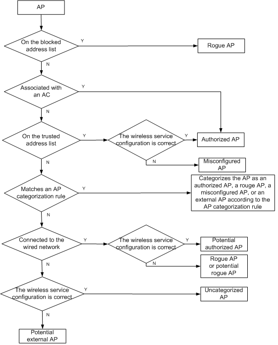
Viewing the detected AP list
1. Click the Service tab.
2. From the navigation tree, select WLAN Manager > WIPS Management > APs Detected.
The Detected AP List displays all detected APs.
Detected AP List contents
¡ Status—State of the AP: ![]() Online or
Online or ![]() Offline.
Offline.
¡ BSSID—BSSID (MAC address) of the AP. Click the BSSID to view the AP details.
¡ SSID—SSID used by the AP. Click the SSID to view the SSID details.
¡ Virtual Security Domain—Virtual security domain to which the sensor that detected the AP belongs.
¡ Category—Category of the AP. Options
are Authorized, Rogue, Ad hoc, Misconfigured,
External, Potential-Authorized,
Potential-Rogue, Potential-External,
and Uncategorized. Click the Modify
icon ![]() to
modify the AP category.
to
modify the AP category.
¡ Threat Level—Threat level of the AP.
¡ Detecting AC—Device label of the AC with which the sensor that detected the AP is associated. Click the label to view the AC details.
¡ Device vendor info—Vendor of the detected AP. If the sensor does not obtain vendor information about the AP, this field displays null.
¡ Last Detection Time—Time when the AP was last detected.
¡ Static List Status—Whether the AP is on the Static Trusted Address List, Alarm-Ignored Address List, Static Blocked Address List, and Countermeasures Address List of an AC.
A green icon ![]() indicates that
the AP is on the list. Click the icon to remove it from the list.
indicates that
the AP is on the list. Click the icon to remove it from the list.
A gray icon ![]() indicates that
the AP is not on the list. Click the icon to add the AP to the list.
indicates that
the AP is not on the list. Click the icon to add the AP to the list.
An AP cannot be on the Static Trusted Address List and the Static Blocked Address List at the same time.
¡ Locate—Click the Locate icon ![]() to display the AP in the location view where the sensor that
detected the AP resides. If the sensor is not in the location view, the operation
fails.
to display the AP in the location view where the sensor that
detected the AP resides. If the sensor is not in the location view, the operation
fails.
If the Detected AP List contains enough entries, the following navigational aids appear:
· Click the Next Page
icon ![]() to page
forward in the Detected AP List.
to page
forward in the Detected AP List.
· Click the Last Page
icon ![]() to page
forward to the end of the Detected AP List.
to page
forward to the end of the Detected AP List.
· Click the Previous Page
icon ![]() to page
backward in the Detected AP List.
to page
backward in the Detected AP List.
· Click the First Page
icon ![]() to page
backward to the front of the Detected AP List.
to page
backward to the front of the Detected AP List.
Click 8, 15, 50, 100, or 200 at the upper right of the list to specify the number of items you want to display on each page.
|
|
NOTE: You can sort the Detected AP List by the BSSID, SSID, Category, and Detected AC fields. Click the column label to sort the list by the selected field. The column label allows you to toggle between the various sort options specific to each field. |
Synchronizing detected APs
By default, IMC synchronizes the most recent detected AP list from managed ACs every 2 hours. You can also manually perform the synchronization operation.
To manually synchronize detected APs:
1. Click the Service tab.
2. From the navigation tree, select WLAN Manager > WIPS Management > APs Detected.
The Detected AP List displays all detected APs.
3. Click Synchronize.
The page is refreshed to display the most recent detected AP list after the synchronization process is completed.
Querying detected APs
WSM provides basic query and advanced query. Basic query criteria include several key parameters for quick searches. Advanced query offers various query criteria for precise matching.
To query detected APs:
1. Click the Service tab.
2. From the navigation tree, select WLAN Manager > WIPS Management > APs Detected.
The Detected AP List displays all detected APs.
3. Perform a basic query:
a. Enter the BSSID (case-insensitive), SSID (case-insensitive), or virtual security domain. WSM supports fuzzy matching for this field.
b. Click the Query icon
![]() . The Detected AP List displays all APs matching the query
criteria.
. The Detected AP List displays all APs matching the query
criteria.
c. Clear the Query field,
and click the Query icon ![]() to display all APs.
to display all APs.
4. Perform an advanced query:
a. Click the Expand
icon ![]() next to the Query field to expand the Query area. Click it again to hide the Query area.
next to the Query field to expand the Query area. Click it again to hide the Query area.
b. In the query area, specify one or more of the following query criteria:
- AC—Select the detecting AC.
- BSSID—Enter a partial or complete BSSID (MAC address) of the AP in the xx:xx:xx:xx:xx:xx format. WSM supports fuzzy matching for this field.
- SSID—Enter a partial or complete SSID used by the AP. WSM supports fuzzy matching for this field.
- Virtual Security Domain—Enter the name of the virtual security domain to which the sensor that detected the AP belongs.
- Category—Select the category of the AP. Options are Authorized, Rogue, Ad hoc, Misconfigured, External, Potential-Authorized, Potential-Rogue, Potential-External, and Uncategorized.
- Last Detection Time—Select the time range when the AP was last detected. Options are All, Last Day, Last Three Days, Last Week, and Last Month.
c. Click Query.
The Detected AP List displays all detected APs matching the query criteria.
d. Click Reset to clear the query criteria and display all detected APs.
Modifying the category of an AP
By default, WIPS categorizes an AP according to the user-defined and system-defined AP categorization rules. You can manually change the category of an AP.
To change the category of an AP:
1. Click the Service tab.
2. From the navigation tree, select WLAN Manager > WIPS Management > APs Detected.
The Detected AP List displays all detected APs.
3. Select one or more APs whose categories you want to modify, and click Modify AP Category in the Detected AP List area.
Or, click the Modify icon ![]() in the Category column
of the target AP.
in the Category column
of the target AP.
The Modify AP Category window opens.
4. Select a new AP category from the Category list.
5. Select a categorization mode from the AP Categorization Mode list. Options include Manual, Automatic Categorization by NMS, and Automatic Categorization by Device.
6. Click OK.
Assigning or removing an AP to or from a static list
1. Click the Service tab.
2. From the navigation tree, select WLAN Manager > WIPS Management > APs Detected.
The Detected AP List displays all detected APs.
3. Select the target AP, and click Operation in the Detected AP List area, and then select Add to Static Trusted Address List, Add to Alarm Ignored Address List, Add to Static Blocked Address List, or Add to Static Countermeasures List from the shortcut menu.
Or, click the Add to list icon
![]() for a
static list in the Static List
Status column of an AP to add it to the static
list. Click the Remove from list icon
for a
static list in the Static List
Status column of an AP to add it to the static
list. Click the Remove from list icon ![]() for a static list in the Static List Status column of an AP to
remove it from the static list.
for a static list in the Static List Status column of an AP to
remove it from the static list.
An AP cannot be on the Static Trusted Address List and the Static Blocked Address List at the same time. To add an AP to either list, first remove it from the other list.
Viewing the detected AP history
1. Click the Service tab.
2. From the navigation tree, select WLAN Manager > WIPS Management > APs Detected.
The Detected AP List displays all detected APs.
3. Click the History
icon ![]() to the
right of the Detected AP List.
to the
right of the Detected AP List.
The Detected AP History List displays all detected AP history records.
Detected AP History List
¡ MAC Address—MAC address of the detected AP. Click the MAC address to view the AP details.
¡ SSID—SSID used by the AP.
¡ Last Detection Time—Time when the AP was last detected.
¡ Disappeared At—Time when the AP can no longer be detected.
¡ Virtual Security Domain—Virtual security domain to which the sensor that detected the AP belongs.
¡ Category—Category of the AP, Authorized, Rogue, Ad hoc, Misconfigured, External, Potential-Authorized, Potential-Rogue, Potential-External, or Uncategorized.
¡ Device vendor info—Vendor of the detected AP. If the sensor does not obtain vendor information about the AP, this field displays null.
¡ Threat Level—Threat level of the AP. The greater the value, the higher the threat level.
¡ Detecting AC—Device label of the AC with which the sensor that detected the AP is associated. Click the label to view the AC details.
4. Click the Back
icon ![]() to
return to the Detected AP List.
to
return to the Detected AP List.
Querying the detected AP history
You can query the detected AP history records by using the query criteria for querying detected APs. For more information, see "Querying detected APs."
Detected client list
The Detected Client List displays the clients detected by all the sensors.
The clients are classified into the following categories:
· Authorized—Clients permitted in the WLAN, including:
¡ Clients in the permitted device list that have associated with authorized APs.
¡ Clients that have been associated with authorized APs by passing authentication and encryption.
· Rogue—Clients prohibited in the WLAN, including:
¡ Clients on the blocked address list.
¡ Clients associated with rogue APs.
· Misassociated—Clients on the trusted address list but are associated with rogue APs.
· Uncategorized—Clients whose category cannot be determined.
WIPS categorizes a detected client by using the process as shown in Figure 69.
Figure 69 Client classification process
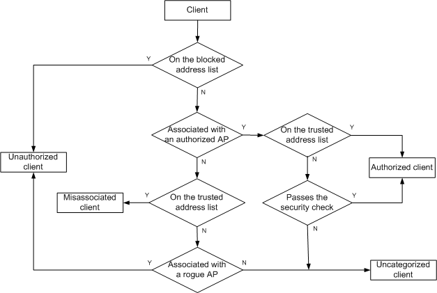
Viewing the detected client list
1. Click the Service tab.
2. From the navigation tree, select WLAN Manager > WIPS Management > Clients Detected.
The Detected Client List displays all detected clients.
Detected Client List contents
¡ Status—Online state of the client, ![]() Online or
Online or ![]() Offline.
Offline.
¡ MAC Address—MAC address of the client.
¡ BSSID—BSSID (MAC address) of the AP with which the client is associated. Click the BSSID to view the AP details.
¡ Virtual Security Domain—Virtual security domain to which the sensor that detected the client belongs.
¡ Category—Category of the client, which can be Authorized, Unauthorized, Misassociated, and Uncategorized.
¡ Detecting AC—Device label of the AC with which the sensor that detected the client was associated. Click the label to view the AC details.
¡ Last Detection Time—Time when the client was first detected.
¡ Static List Status—Whether the client is on the Static Trusted Address List, Alarm-Ignored Address List, Static Blocked Address List, and Countermeasures Address List.
The green icon ![]() indicates that
the client is on the list. Click the icon to remove the client from the list.
indicates that
the client is on the list. Click the icon to remove the client from the list.
The gray icon ![]() indicates that
the client is not on the list. Click the icon to add the client to the list.
indicates that
the client is not on the list. Click the icon to add the client to the list.
An AP cannot be on the Static Trusted Address List and the Static Blocked Address List at the same time.
¡ Locate—Click the Locate icon ![]() to display the client in the location view where the sensor that
detected the client resides. If the sensor is not in the location view, the operation
fails.
to display the client in the location view where the sensor that
detected the client resides. If the sensor is not in the location view, the operation
fails.
If the Detected Client List contains enough entries, the following navigational aids appear:
· Click the Next Page
icon ![]() to page
forward in the Detected Client List.
to page
forward in the Detected Client List.
· Click the Last Page
icon ![]() to page
forward to the end of the Detected Client List.
to page
forward to the end of the Detected Client List.
· Click the Previous Page
icon ![]() to page
backward in the Detected Client List.
to page
backward in the Detected Client List.
· Click the First Page
icon ![]() to page
backward to the front of the Detected Client List.
to page
backward to the front of the Detected Client List.
Click 8, 15, 50, 100, or 200 at the upper right of the list to specify the number of items you want to display on each page.
|
|
NOTE: You can sort the Detected Client List by all fields except the Static List Status field. Click the column label to sort the list by the selected field. The column label allows you to toggle between the various sort options specific to each field. |
Synchronizing detected clients
By default, IMC synchronizes the most recent client information detected by WIPS from managed ACs every 2 hours. You can also manually perform the synchronization operation.
To manually synchronize detected client information from managed ACs:
1. Click the Service tab.
2. From the navigation tree, select WLAN Manager > WIPS Management > Clients Detected.
The Detected Client List displays all detected clients.
3. Click Synchronize.
The page is refreshed to display the most recent detected client list after the synchronization process is completed.
Querying detected clients
WSM provides basic query and advanced query. Basic query criteria include several key parameters for quick searches. Advanced query offers various query criteria for precise matching.
To query detected clients:
1. Click the Service tab.
2. From the navigation tree, select WLAN Manager > WIPS Management > Clients Detected.
The Detected Client List displays all detected clients.
3. Perform a basic query:
a. Enter the MAC address or virtual security domain name. WSM supports fuzzy matching for this field.
b. Click the Query icon
![]() . The AC List displays all ACs matching the query criteria.
. The AC List displays all ACs matching the query criteria.
c. Clear the Query
field, and click the Query icon ![]() to display all
ACs.
to display all
ACs.
4. Perform an advanced query:
a. Click the Expand
icon ![]() next to the Query field to expand the Query area. Click it again to hide the Query area.
next to the Query field to expand the Query area. Click it again to hide the Query area.
b. In the query area, specify one or more of the following query criteria:
- AC—Select the AC with which the sensor that detected the client is associated.
- MAC Address—Enter a partial or complete MAC address of the client in the xx:xx:xx:xx:xx:xx format. WSM supports fuzzy matching for this field.
- Virtual Security Domain—Enter the name of the virtual security domain to which the sensor that detected the client belongs.
- BSSID—Enter a partial or complete BSSID (MAC address) of the AP with which the client is associated. WSM supports fuzzy matching for this field.
- Category—Select the client category from the list. Options are All, Authorized, Unauthorized, Misassociated, and Uncategorized.
- Last Detection Time—Select the time range when the client was last detected. Options are All, Last Day, Last Three Days, Last Week, and Last Month.
c. Click Query.
The Detected Client List displays all detected clients matching the query criteria.
d. Click Reset to clear the query criteria and display all detected clients.
Viewing the detected client details
1. Click the Service tab.
2. From the navigation tree, select WLAN Manager > WIPS Management > Clients Detected.
The Detected Client List displays all detected clients.
3. Click the MAC address of the client whose detailed information you want to view.
The Client Details page opens.
Basic Client Information
¡ MAC Address—MAC address of the client.
¡ Detecting AC—Device label of the AC with which the sensor that detected the client is associated. Click the label to view the AC details.
¡ Virtual Security Domain—Name of the virtual security domain to which the sensor that detected the client belongs.
¡ Whether Countermeasures Are Taken—Whether WIPS has taken countermeasures against the client, Yes or No.
¡ Sensors That Have Detected the Clients—Number of sensors that have detected the client.
¡ BSSID—BSSID (MAC address) of the AP with which the client is associated.
¡ First Detection Time—Time when the client was first detected.
¡ Last Detection Time—Time when the client was last detected.
¡ Status—Current online state of the client.
¡ Station Status—Whether the client was associated with the AP when it was last detected: Associated or Disassociated.
¡ Channel—Channel used by the client and AP to communicate with each other.
¡ Category—Category of the client: Authorized, Unauthorized, Misassociated, or Uncategorized.
¡ Radio Type—Type of the radio with which the client is associated: 802.11a, 802.11b, 802.11g, 802.11an, or 802.11gn.
Sensor List
The Sensor List displays all sensors that detected the client.
¡ Status—Current state of the sensor: ![]() Online or
Online or ![]() Offline.
Offline.
¡ AP Label—Device label of the sensor. Click the label to view the sensor details.
¡ Last Detection Time—Time when the sensor last detected the client.
¡ RSSI (dBm)—RSSI value of the sensor.
¡ Radio ID—ID of the radio that detected the client.
Latest WIPS Security Event List
The Latest WIPS Security Event List displays all security events related to the client.
¡ Level—Severity level of the security event. Security levels include Emergency, Alarm, Key, Error, Warning, Notification, Prompt, and Debugging.
¡ Sensor MAC Address—MAC address of the sensor that detected the client.
¡ Virtual Security Domain—Virtual security domain to which the sensor that detected the client belongs.
¡ Event Type—Security event type.
¡ Description—Description of the security event.
¡ Generated At—Time when the security event occurred.
Assigning or removing a detected client to or from a static list
1. Click the Service tab.
2. From the navigation tree, select WLAN Manager > WIPS Management > Clients Detected.
The Detected Client List displays all detected clients.
3. Select the target client, click Operation in the Detected AP List area, and then select Add to Static Trusted Address List, Add to Alarm Ignored Address List, Add to Static Blocked Address List, or Add to Static Countermeasures List from the shortcut menu.
Or,
Click the Add to list icon ![]() for a static list
in the client Static List Status column to add the client to the list. Click the Remove from list
icon
for a static list
in the client Static List Status column to add the client to the list. Click the Remove from list
icon ![]() to
remove the client from a list.
to
remove the client from a list.
A client cannot be on the Static Trusted Address List and the Static Blocked Address List at the same time. To add a client to either list, remove it from the other list first.
Viewing the detected client history
1. Click the Service tab.
2. From the navigation tree, select WLAN Manager > WIPS Management > Clients Detected.
The Detected Client List displays all detected clients.
3. Click the History
icon ![]() located
to the right of the Detected Client List.
located
to the right of the Detected Client List.
The Detected Client History List displays all detected client history records.
Detected Client History List contents
¡ Client MAC—MAC address of the client. Click the MAC address to view the client details.
¡ BSSID—BSSID (MAC address) of the AP with which the client was associated.
¡ Last Detection Time—Time when the client was last detected.
¡ Disappeared At—Time when the client logged off.
¡ Virtual Security Domain—Virtual security domain to which the sensor that detected the client belongs.
¡ Category—Category of the client. Options are Authorized, Unauthorized, Misassociated, and Uncategorized.
¡ Detecting AC—Device label of the AC with which the sensor that detected the AP was associated. Click the label to view the AC details.
4. Click the Back
icon ![]() on the right-top corner of the Detected
Clients History List to return to the Detected Client List page.
on the right-top corner of the Detected
Clients History List to return to the Detected Client List page.
Querying the detected client history
Querying the detected client history is similar to querying detected clients. For more information, see "Querying detected clients."
Detected SSIDs
The sensors scan the channels supported by the country code, and collect statistics on the SSIDs being used on the channels.
Viewing the detected SSID list
1. Click the Service tab.
2. From the navigation tree, select WLAN Manager > WIPS Management > SSIDs Detected.
The Detected SSID List displays all detected SSIDs.
Detected SSID List
¡ Status—State of the SSID: Inactive or Active. An active SSID becomes inactive if no frames carrying the SSID are transmitted within the specified time period. An inactive SSID is deleted from the Detected SSID List after its lifetime exceeds the specified aging time.
¡ SSID—Click the SSID to view its details.
¡ Virtual Security Domain—Virtual security domain to which the sensor that detected the SSID belongs.
¡ Hide SSID—Whether the SSID is hidden in the beacon frames sent by the APs.
¡ AP Count—Number of APs using the SSID.
¡ Detecting AC—Device label of the AC with which the sensor that detected the SSID is associated. Click the label to view the AC details.
¡ Last Detection Time—Time when the SSID was last detected.
If the Detected SSID List contains enough entries, the following navigational aids appear:
¡ Click
the Next Page icon ![]() to page forward in the Detected SSID List.
to page forward in the Detected SSID List.
¡ Click
the Last Page icon ![]() to page forward to the end of the Detected
SSID List.
to page forward to the end of the Detected
SSID List.
¡ Click
the Previous Page icon ![]() to page backward in the Detected SSID List.
to page backward in the Detected SSID List.
¡ Click
the First Page icon ![]() to page backward to the front of the Detected
SSID List.
to page backward to the front of the Detected
SSID List.
3. Click 8, 15, 50, 100, or 200 at the upper right of the Detected SSID List to specify the number of items you want to display on each page.
|
|
NOTE: You can sort the Detected SSID List by the SSID, AP Count, and Detected AC fields. Click the column label to sort the list by the selected field. The column label allows you to toggle between the various sort options specific to each field. |
Synchronizing detected SSIDs
By default, IMC synchronizes the SSIDs detected by WIPS from managed ACs every 2 hours. You can also manually perform the synchronization operation.
To manually synchronize SSIDs from the ACs:
1. Click the Service tab.
2. From the navigation tree, select WLAN Manager > WIPS Management > Clients Detected.
The Detected SSID List displays all detected SSIDs.
3. Click Synchronize.
The page is refreshed to display the most recent detected SSID address list after the synchronization process is completed.
Querying detected SSIDs
WSM provides basic query and advanced query. Basic query criteria include several key parameters for quick searches. Advanced query offers various query criteria for precise matching.
To query detected SSIDs:
1. Click the Service tab.
2. From the navigation tree, select WLAN Manager > WIPS Management > SSIDs Detected.
The Detected SSID List displays all detected SSIDs.
3. Perform a basic query:
a. Enter the SSID (case-insensitive) or virtual security domain name. WSM supports fuzzy matching for this field.
b. Click the Query icon
![]() . The Detected SSID List displays all SSIDs matching the query
criteria.
. The Detected SSID List displays all SSIDs matching the query
criteria.
c. Clear the Query
field, and click the Query icon ![]() to display all SSIDs.
to display all SSIDs.
4. Perform an advanced query:
a. Click the Expand
icon ![]() next to the Query field to expand the Query area. Click it again to hide the Query area.
next to the Query field to expand the Query area. Click it again to hide the Query area.
b. In the Query Criteria area, specify one or more of the following query criteria:
- AC—Select the AC with which the sensor that detected the SSID is associated.
- SSID—Enter a partial or complete SSID you want to query.
- Virtual Security Domain—Enter the name of the virtual security domain to which the sensor that detected the SSID belongs.
- Status—Select a state of the SSID. Options are Active, Inactive, and All.
- Last Detection Time—Select the time range when the SSID was last detected. Options are All, Last Day, Last Three Days, Last Week, and Last Month.
The Detected SSID List displays all detected SSIDs matching the query criteria.
d. Click Reset to clear the query criteria and display all detected SSIDs.
Viewing the detected SSID details
1. Click the Service tab.
2. From the navigation tree, select WLAN Manager > WIPS Management > Clients Detected.
The Detected SSID List displays all detected SSIDs.
3. Click the SSID whose detailed information you want to view.
The SSID Details page opens.
Basic SSID Information
¡ SSID—SSID.
¡ Detecting AC—Device label of the AC with which the sensor that detected the SSID was associated. Click the label to view the AC details.
¡ Number of APs of the SSID—Total number of APs using the SSID.
¡ Virtual Security Domain—Virtual security domain to which the sensor that detected the SSID belongs.
¡ Hide SSID—Whether the SSID is hidden in the beacon frames sent by the APs.
¡ First Detection Time—Time when the SSID was first detected.
¡ Last Detection Time—Time when the SSID was last detected.
¡ Status—State of the SSID, Active or Inactive. By default, a detected SSID is in Active state. If no frames carrying the SSID are transmitted within the specified time period, the SSID state is set to Inactive.
¡ Security Method—Security method used by the frames carrying the SSID.
¡ Encryption Method—Encryption method used by the frames carrying the SSID.
¡ Authentication Method—Authentication method used by the frames carrying the SSID.
APs of the SSID
The APs of the SSID area displays all APs using the SSID.
¡ BSSID—BSSID (MAC address) of the AP using the SSID.
¡ Channel—Channels used by the SSID.
¡ Client Count—Total number of clients using the SSID to access the wireless network.
Viewing the detected SSID history
1. Click the Service tab.
2. From the navigation tree, select WLAN Manager > WIPS Management > SSIDs Detected.
The Detected SSID List displays all detected SSIDs.
3. Click the History
icon ![]() to the
right of the Detected SSID List.
to the
right of the Detected SSID List.
The Detected SSID History List displays all history records of the detected SSID.
Detected SSID History List contents
¡ SSID—Click the SSID to view its details. For more information about SSID details, see "Viewing the detected SSID details."
¡ Virtual Security Domain—Virtual security domain to which the sensor that detected the SSID belongs.
¡ Last Detection Time—Time when the SSID was last detected.
¡ Disappeared at—Time when the SSID can no longer be detected.
¡ Security Method—Security method used by the SSID, Clear, WEP, WPA, WPA2, or WPA/WPA2.
¡ Detecting AC—Device label of the AC with which the sensor that detected the SSID is associated. Click the label to view the AC details.
Querying the detected SSID history
You can query the detected SSID history by using the query criteria for querying detected SSIDs. For more information, see "Querying detected SSIDs."
Security event
A security event is an event or operation in the wireless network that is recorded in a syslog message. APs periodically report detected information to the AC, which records the information in syslogs and sends the syslogs to IMC. You can view the syslogs on the WIPS Security Event List.
To view the WIPS security event list, make sure the following conditions are met:
· The Syslog Management module has been installed and deployed.
· You have configured the IMC server (IP address) as the log host of the AC with the info-center loghost xxxx command, where xxxx is the IP address of the primary IMC server.
Viewing the WIPS security event list
1. Click the Service tab.
2. From the navigation tree, select WLAN Manager > WIPS Management > Security Event.
The WIPS Security Event List displays all security events.
WIPS Security Event List contents
¡ Security Level—Severity level of the security event. Options are Emergency, Alarm, Key, Error, Warning, Notification, Prompt, and Debugging.
¡ Detected Device MAC—MAC address of the device on which the event occurred.
¡ Detecting Device MAC—MAC address of the device that detected the security event.
¡ Virtual Security Domain—Virtual Security domain to which the sensor that detected the security event belongs.
¡ Event Type—Security event type. For example, vsd-client-del or vsd-ap-add.
¡ Detecting AC—Device label of AC with which the sensor that detected the security event was associated. Click the AC label to view its details.
¡ Description—Description of the security event.
¡ Receive Time—Time when the syslog that recorded the security event was received.
¡ Locate—Click the Locate icon ![]() to display the device in the location view where the sensor that
detected the device resides. If the sensor is not in the location view, the operation
fails.
to display the device in the location view where the sensor that
detected the device resides. If the sensor is not in the location view, the operation
fails.
If the WIPS Security Event List contains enough entries, the following navigational aids appear:
¡ Click
the Next Page icon ![]() to page forward in the WIPS Security Event
List.
to page forward in the WIPS Security Event
List.
¡ Click
the Last Page icon ![]() to page forward to the end of the WIPS
Security Event List.
to page forward to the end of the WIPS
Security Event List.
¡ Click
the Previous Page icon ![]() to page backward in the WIPS Security Event
List.
to page backward in the WIPS Security Event
List.
¡ Click
the First Page icon ![]() to page backward to the front of the WIPS
Security Event List.
to page backward to the front of the WIPS
Security Event List.
3. Click 8, 15, 50, 100, or 200 at the upper right of the WIPS Security Event List to specify the number of items you want to display on each page.
|
|
NOTE: You can sort the WIPS Security Event List by all fields. Click the column label to sort the list by the selected field. The column label allows you to toggle between the various sort options specific to each field. |
Querying security events
WSM provides basic query and advanced query. Basic query criteria include several key parameters for quick searches. Advanced query offers various query criteria for precise matching.
To query security events:
1. Click the Service tab.
2. From the navigation tree, select WLAN Manager > WIPS Management > Security Event.
The WIPS Security Event List displays all security events.
3. Perform a basic query:
a. Enter the virtual security domain name or security event. WSM supports fuzzy matching for this field.
b. Click the Query icon
![]() . The WIPS Security Event List displays all security events
matching the query criteria.
. The WIPS Security Event List displays all security events
matching the query criteria.
c. Clear the Query
field, and click the Query icon ![]() to display all security
events.
to display all security
events.
4. Perform an advanced query:
a. Click the Expand
icon ![]() next to the Query field to expand the Query area. Click it again to hide the Query area.
next to the Query field to expand the Query area. Click it again to hide the Query area.
b. Specify one or more of the following query criteria:
- Detected Device MAC—Enter a partial or complete MAC address of the device where the security event occurred, in the xx:xx:xx:xx:xx:xx format. WIPS supports fuzzy matching for this field.
- Detecting Device MAC—Enter a partial or complete MAC address of the device that detect the security event, in the xx:xx:xx:xx:xx:xx format. WIPS supports fuzzy matching for this field.
- Virtual Security Domain—Enter a partial or complete security domain name to which the sensor that detected the security event belongs.
- Receive Time—Select the time range during which the security event occurred. Options are All, Last Day, Last Three Days, Last Week, and Last Month.
- Event Type—Enter the security event type. WSM supports fuzzy matching for this field.
- Severity Level—Select a severity level for the security event. Options are Emergency, Alarm, Key, Error, Warning, Notification, Prompt, and Debugging.
c. Click Query.
The WIPS Security Event List displays all security events matching the query criteria.
d. Click Reset to clear the query criteria and display all security events.
Deleting security events
1. Click the Service tab.
2. From the navigation tree, select WLAN Manager > WIPS Management > Security Event.
The WIPS Security Event List displays all security events.
3. Select one or more security events you want to delete.
4. Click Delete.
5. In the confirmation dialog box, click OK.
WLAN probing
WLAN probing enables APs to scan channels to collect device information and send the information to WSM for device quantity and location analysis in real time. It can locate unassociated clients.
WLAN probing and WIPS cannot be used at the same time.
WLAN probing networking
As shown in Figure 70, you can configure an AP to operate in monitor mode or hybrid mode. For more information about WLAN probing configuration for an AP, see the related device manual.
Figure 70 WLAN probing network
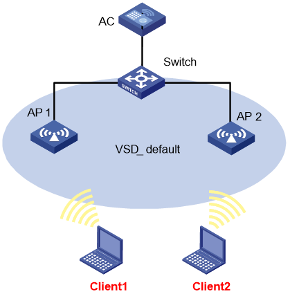
Detected client graphs
The detected client graphs display client count or trend by location view. To view detected client graphs for specific location views, you need to customize the location views first. For more information about customizing location or sublocation views, see "Customizing location views."
Detected Client Count by Location View
The graph displays the number of associated and unassociated clients by location view. Clients in sublocations are not included.
Figure 71 Detected Client Count by Location View
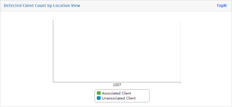
Click TopN on the upper right of the graph. The TopN Location Views by Client Count page opens.
Figure 72 Top N Location Views by Client Count
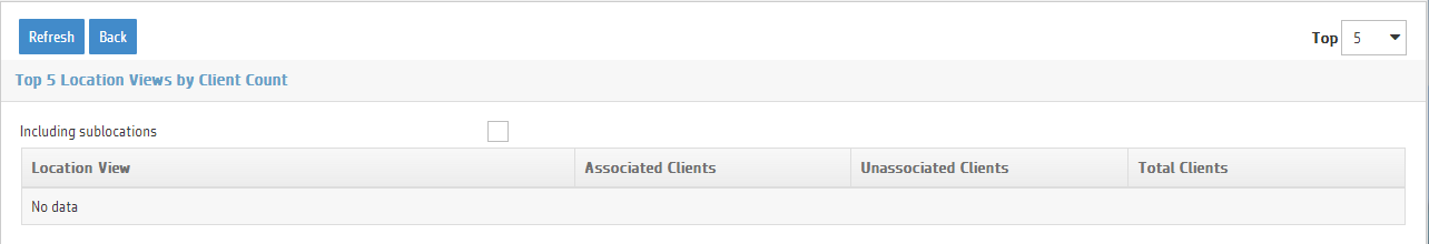
· Select a number from the TopN list on the upper right of the figure. Options are 5, 10, 20, 50, and 100.
· To include clients in sublocations in the Top N Location Views by Client Count List, select Including sublocations.
Detected Client Trend Graph
The graph displays online client trend and peak and average online client counts.
Figure 73 Detected Client Trend Graph
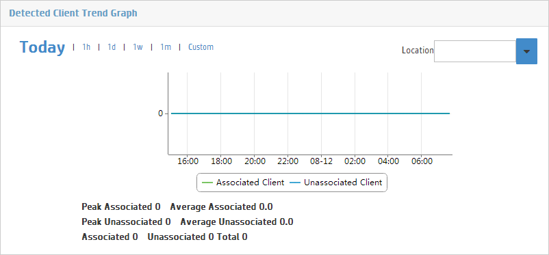
The horizontal axis represents the time, and the vertical axis represents the number of clients. You can click a time range link on the upper left to view online client count changes within a specific time range. Options are Today, 1h, 1d, 1w, 1m, and Custom. The time increments on the horizontal axis change as you click different time range links.
You can select a location or sublocation from the Location list on the upper right of the graph to view the client trend for the location or sublocation.
Viewing the probing information
The Probing Info page displays information about all detected devices, including APs and clients.
To view the probing information:
1. Click the Service tab.
2. From the navigation tree, select WLAN Manager > WIPS Management > Probing Info.
The Probing Info page displays detected client graphs and a detected device list. For more information about the detected client graphs, see "Detected client graphs."
Detected Device List
¡ MAC Address—MAC address of the device.
¡ Category—Type of the device. Options include Related Detection of AP Clients, Associated With Other AP Clients, Non Associated Clients, and Neighbor AP.
¡ SSID—SSID of the connected network. This field is empty for an unassociated client.
¡ BSSID—MAC address of the associated AP. This field is empty for an unassociated client or a neighbor AP.
¡ Channel—Working channel of the device.
¡ Detected AP—Name of the AP that detected the device.
¡ Location—Name of the location view where the detecting AP is located.
¡ RSSI—RSSI of the device.
¡ Noise—Noise floor detected by the detecting AP. Noise floor affects channel quality and changes with the temperature.
¡ Encryption Method—Encryption method used by the device.
¡ First Detection Time—Time when the device was first detected.
¡ Last Detection Time—Time when the device was last detected.
¡ Online Time—Total online time of the device.
¡ Detecting AC—Name of the AC with which the detecting AP is associated.
Querying the probing information
1. Click the Service tab.
2. From the navigation tree, select WLAN Manager > WIPS Management > Probing Info.
The Detected Device List displays all detected devices.
3. Perform a basic query:
a. Enter the MAC address. WSM supports fuzzy matching for this field.
b. Click the Query icon
![]() . The Detected Device List displays all devices matching the query criteria.
. The Detected Device List displays all devices matching the query criteria.
c. Clear the Query
field, and click the Query icon ![]() to display all detected devices.
to display all detected devices.
4. Perform an advanced query:
a. Click the Expand
icon ![]() next to the Query field to expand the Query area. Click it again to hide the Query area.
next to the Query field to expand the Query area. Click it again to hide the Query area.
b. In the Query Criteria area, specify one or more of the following query criteria:
- AC—Select the detecting AC.
- MAC Address—Enter the MAC address of the device.
- Location—Select a location view where the detecting AP is located.
- Device Type—Select the device type. Options are All, Related Detection of AP Clients, Associated With Other AP Clients, Non Associated Clients, and Neighbor AP.
- Last Detection Start Time—Select the start time for the query time range.
- Last Detection End Time—Select the end time for the query time range.
- Duplicate MAC Filter—Select whether to filter duplicate devices. Options are Yes and No. If you select Yes, WSM filters devices with the same MAC address and displays only the device detected most recently.
- Detected AP—Select the detecting AP.
c. Click Query.
The Detected Device List displays all devices matching the query criteria.
d. Click Reset to clear the query criteria and display all detected devices.
Customizing location views
Perform this task to customize location views for detected client graphs.
To customize location views:
1. Click the Service tab.
2. From the navigation tree, select WLAN Manager > WIPS Management > Probing Info.
3. Click Customize Location Views on the page.
4. Select one or more location views. By default, all sublocation views in a location view are selected. You can also customize graphs for sublocation views.
5. Click OK.
Viewing the detected devices of an AP
1. Click the Service tab.
2. From the navigation tree, select WLAN Manager > WIPS Management > Probing Info.
3. In the Detected Device list, click the name of a detecting AP.
The Detected Device list displays all devices detected by the AP.
Detected Device List
¡ MAC Address—MAC address of the device.
¡ Category—Type of the device. Options include Related Detection of AP Clients, Associated With Other AP Clients, Non Associated Clients, and Neighbor AP.
¡ SSID—SSID of the connected network. This field is empty for an unassociated client.
¡ BSSID—MAC address of the associated AP. This field is empty for an unassociated client or a neighbor AP.
¡ Channel—Working channel of the device.
¡ RSSI—RSSI of the device.
¡ Noise—Noise floor detected by the detecting AP. Noise floor affects channel quality and changes with the temperature.
¡ Encryption Method—Encryption method used by the device.
¡ First Detection Time—Time when the device was first detected.
¡ Last Detection Time—Time when the device was last detected.
¡ Online Time—Total online time of the device.
4. Click the Close icon ![]() to close the window.
to close the window.
Viewing the probing information history
1. Click the Service tab.
2. From the navigation tree, select WLAN Manager > WIPS Management > Probing Info.
3. Click History.
The Probing Info History page opens.
Probing Info History List
¡ MAC Address—MAC address of the device.
¡ Category—Type of the device. Options include Related Detection of AP Clients, Associated With Other AP Clients, Non Associated Clients, and Neighbor AP.
¡ SSID—SSID of the connected network. This field is empty for an unassociated client.
¡ BSSID—MAC address of the associated AP. This field is empty for an unassociated client or a neighbor AP.
¡ Channel—Working channel of the device.
¡ Detected AP—Name of the AP that detected the device.
¡ Location—Name of the location view where the detecting AP is located.
¡ RSSI—RSSI of the device.
¡ Noise—Noise floor detected by the detecting AP. Noise floor affects channel quality and changes with the temperature.
¡ Encryption Method—Encryption method used by the device.
¡ First Detection Time—Time when the device was first detected.
¡ Last Detection Time—Time when the device was last detected.
¡ Online Time—Total online time of the device.
¡ Detecting AC—Name of the AC with which the detecting AP is associated.
4. Click Back to return to the Probing Info page.
Data export
WSM supports data export to reduce the workload on the database. Data that can be exported include detected AP, detected client, detected SSID, security event, and WLAN probing information. For more information about data export, see H3C IMC v7.3 Enterprise and Standard Platform Administrator Guide.
To configure data export:
1. Click the System tab.
2. From the navigation tree, select System Configuration > Data Export.
The Data Export Settings page opens.
3. Click the target tab to open the settings page.
4. Configure the following parameters:
¡ Select the triggering method:
- By Quantity—Export data if the number of saved entries in the database reaches the threshold. Set the Export but the last value to configure WSM to save the specified number of entries generated most recently in the database and export the other entries.
- By Time—Export data if any entry has been saved in the database longer than the threshold. Set the Export but those in last value to configure WSM to save entries generated within the specified time and export the other entries.
If you select both By Quantity and By Time, WSM uses the method that allows the database to save more entries.
¡ Configure export settings:
- Target File Type—Select the target file type. Options are CSV and HTML.
- Save File for—Enter the number of days that an exported file can be saved.
- Execute Command After Export—Specify a command that does not need a GUI operation. The command can be an executable or batch command.
- Target File Path—This field displays the directory for saving exported files. To change the directory, click Change Export Directory on the upper right of the page.
- Last Export—This field displays the time for the most recent export.
5. Click OK. WSM examines the database at 2 a.m. every day to determine whether to perform the data export. To enable WSM to examine the database immediately, click Export Immediately on the upper right of the page.
Configuring network planning
WSM network planning can plan the location and number of APs in your network according to the AP model, transmission power, and on-site conditions before you deploy or extend a WLAN. Then, WSM generates a network planning report. This function improves WLAN deployment efficiency.
To plan a wireless network, see the following information:
· Create a location view. For more information, see "Managing wireless views."
· Entering a location view topology
· Viewing the signal coverage of virtual APs to complete the signal coverage
· Generating a network planning report
All operations in this chapter are performed in a location view.
Entering a location view topology
1. Click the Service tab.
2. From the navigation tree, select WLAN Manager > View Management > Location View.
The Location List displays all location views.
3. Enter the location view in one of the following ways:
¡ Click
the View Topology icon ![]() for the location whose
topology you want to view.
for the location whose
topology you want to view.
¡ Click
the name link of the target location view, and at the upper right of the page that
opens, click the View Topology icon ![]() .
.
The location view topology displays all sublocations and APs in the current location view.
Adding a background picture
1. On the toolbar at the top of the topology page,
click the Add background icon![]() .
.
The Topo Background-Picture Setting window opens.
2. Select a background picture by using one of the following methods:
To use a local picture:
a. Select Upload Image, and then click Choose File on the page.
A window opens.
b. Select a picture, and then click Open.
c. In the Topo Background-Picture Setting window, click Preview.
The selected picture appears in the window.
To select another picture, click Exit.
a. Click Set. The background picture appears in the location view.
To use a picture from the server:
b. Select Select from Gallery.
c. Select a picture, and then click Set.
The selected picture appears in the location view.
To use a CAD file:
a. Select Upload CAD File, and then click Choose File on the page.
A window opens.
b. Select a CAD file, and then click Open.
c. In the Topo Background-Picture Setting window, click Merge into Picture.
The selected picture appears in the location view.
To use a GIS map:
a. Select Use GIS Map.
b. Set the longitude and latitude, and then click Set.
The GIS map appears with the center at the specified longitude and latitude in the location view.
3. Click Close.
Setting a scale
Set an appropriate scale to test signal coverage or to plan a wireless network.
To set a scale:
1. On the toolbar at the top of the topology page,
click the Set Scale icon ![]() .
.
2. Draw a line on the background picture.
The Specify the actual distance window opens.
3. Enter a value in the Actual Distance field, and select a measure unit. Options are Meter and Feet.
4. Click OK.
Drawing obstacles
WSM has predefined obstacles, such as doors, windows, and elevators. You can add the obstacles to a location view.
Adding an obstacle
1. On the toolbar at the top of the topology page,
click the Add Obstacle icon ![]() .
.
The Add Obstacle window opens.
2. Configure the following parameters:
¡ Shape—Select an obstacle shape from the following:
- Line
- Polyline
- Rectangle
- Polygon
- Rectangle Area
¡ Type—Select an obstacle type from the following:
- Concrete (24dB/m)
- Brick Wall (33dB/m)
- Dry Wall (30dB/m)
- Window (200dB/m)
- Elevator Shaft (150dB/m)
- Cubical (10dB/m)
- Thin Door (25dB/m)
- Bookshelf (24dB/m)
¡ Thickness (m)—Enter the thickness of the obstacle, in meters.
¡ Attenuation (dB)—Calculated automatically based on the obstacle type and thickness.
3. Click OK
You are in draw mode.
4. Drag the cursor to draw the obstacle.
5. Double-click to finish drawing the obstacle.
In draw mode, you can add more obstacles of the same type by dragging and dropping the cursor.
6. On the toolbar at the top of the topology page,
click the Pointer icon ![]() to exit draw mode.
to exit draw mode.
Modifying an obstacle
1. Right-click the obstacle to be modified, and select Modify from the shortcut menu.
2. Modify the following parameters:
¡ Serial—Cannot be modified.
¡ Shape—Cannot be modified.
¡ Type—Modify the obstacle type:
- Concrete (24dB/m)
- Brick Wall (33dB/m)
- Dry Wall (30dB/m)
- Window (200dB/m)
- Elevator Shaft (150dB/m)
- Cubical (10dB/m)
- Thin Door (25dB/m)
- Bookshelf (24dB/m)
¡ Thickness (m)—Modify the thickness of the obstacle, in meters.
¡ Attenuation (dB)—Calculated automatically based on the obstacle type and thickness.
3. Click OK.
The modified obstacle appears in the location view.
Deleting an obstacle
You cannot delete an obstacle in draw mode.
Before you delete an obstacle, make sure the Hand icon
![]() rather than the Pointer icon
rather than the Pointer icon ![]() appears on the
toolbar at the top of the topology page.
appears on the
toolbar at the top of the topology page.
To delete an obstacle:
1. Right-click the obstacle to be deleted.
2. In the confirmation dialog box, click OK.
Enabling network planning
With network planning enabled, WSM automatically plans the numbers and locations of APs in a network and generates network planning reports.
Before you enable network planning, delete all virtual APs, if any, in the location view. You can draw a new area or use an old one.
To enable network planning:
1. Right-click on a blank area, and select Plan Network > Draw Covered Area from the shortcut menu.
The Auto Plan Parameters window opens.
2. Configure the following parameters:
¡ 2.4G—Select this option to enable 2.4-GHz radios. If you select this option, you must select a radio type. Options are 802.11b, 802.11g, and 802.11gn.
¡ 5G—Select this option to enable 5-GHz radios. If you select this option, you must select a radio type. Options are 802.11a and 802.11an.
¡ AP Vendor—Select the vendor for the virtual AP. Options are H3C and HP.
¡ AP Model—Select the virtual AP model. The AP model is refreshed automatically to keep consistency with the AP vendor.
¡ Minimum Signal Strength (dBm)—Enter the minimum signal strength value. The default is –70 dBm. Devices must be detected at signals greater than –75 dBm. No fewer than three access points should have signal detection levels below –75 dBm.
¡ Concurrent Online User Count—Enter the allowed maximum number of concurrent online users. This option guarantees the bandwidth for each user in the planned region.
¡ Per-User Bandwidth (Mbps)—Enter the minimum per-user bandwidth. The average bandwidth for a user in the planned region must not be less than the minimum per-user bandwidth.
¡ Power Usage (%)-2.4GHz—Select a 2.4 GHz-band power usage value from the list for all APs in the location view. This parameter takes effect on the entire location. For example, changing the power usage in one area in the location view also changes the power value in another area.
¡ Power Usage (%)-5GHz—Select a 5 GHz-band power usage value from the list for all APs in the location view. This parameter takes effect on the entire location. For example, changing the power usage in one area in the location view also changes the power value in another area.
3. Click OK.
You are in network region planning mode.
4. Click and drag the cursor on the background picture, and click at the desired positions to draw a network planning area.
5. To manually exit network region planning
mode, click the Pointer icon ![]() on the toolbar at the
top of the topology page at any time.
on the toolbar at the
top of the topology page at any time.
6. Double-click to finish drawing the network planning area.
The system exits network region planning mode automatically. The network planning area is highlighted on the background picture.
7. Right-click on a blank area, and select Plan Network > Auto Lay APs from the shortcut menu.
8. The blue AP icons indicate where to deploy APs.
Viewing the signal coverage of virtual APs
After network planning, you can view the signal coverage of virtual APs and adjust AP numbers or AP locations based on the coverage. To view signal coverage, see "Displaying a signal coverage area map," "Setting colors," and "Configuring signal coverage parameters."
Deploying virtual APs
You can adjust AP deployment based on the signal coverage.
Adding a virtual AP to the current location
After you enable the network planning function, you can add one or more virtual APs manually to a location to complete signal deployment.
To add a virtual AP to the current location:
1. Right-click on a blank area, and select Add Virtual APs from the shortcut menu.
The Select AP Model window opens.
2. Select an AP model, and click OK.
You return to the location view, and enter adding virtual AP mode.
3. Click the spot where the virtual AP is to be added.
The added virtual AP appears on the spot.
4. Press the ESC key to exit the mode.
Modifying a virtual AP
1. Right-click the virtual AP to be modified, and select Modify Virtual AP from the shortcut menu.
2. Enter a new AP label in the AP Label field.
3. Modify the radio configuration.
One or more radio configuration tabs might appear, depending on the virtual AP model. The configuration methods are the same for all radios. This example modifies the parameters of Radio 1.
¡ Model—Cannot be modified.
¡ Enable—Enable or disable the radio.
¡ Radio Type—Select a radio type from the following:
- 802.11a
- 802.11b
- 802.11g
- 802.11an
- 802.11gn
¡ Channel—Select the channel where the radio is operating.
¡ Power(dBm)—Enter the radio power, in dBm.
¡ Bandwidth Mode—Select the bandwidth mode. Options are 20MHz and 40MHz. This option is available only for the radio types 802.11an and 802.11gn.
¡ A-MPDU—Enable or disable A-MPDU. This option is available only for the radio types 802.11an and 802.11gn.
¡ A-MSDU—Enable or disable A-MSDU. This option is available only for the radio types 802.11an and 802.11gn.
¡ Short GI—Enable or disable short GI. This option is available only for the radio types 802.11an and 802.11gn.
¡ Antenna—Select an antenna.
¡ Angle—Enter an antenna angle, in the range 0 to 359. Click Refresh to view the signal coverage area of the virtual AP.
4. Click OK.
Deleting a virtual AP
1. Right-click the virtual AP to be deleted, and select Delete Device from this Location from the shortcut menu.
2. In the confirmation dialog box, click OK.
Deleting all virtual APs
1. Right-click on a blank area, and select Delete All Virtual APs from the shortcut menu.
2. In the confirmation dialog box, click OK.
You can perform network planning only after all virtual APs are deleted in the location view.
Generating a network planning report
A network planning report can be generated for viewing after you finish network planning and signal cover simulation tests. The network planning report is an HTML file that contains numbers and descriptions for selected APs and antennas, an AP deployment map, and signal coverage prediction heat maps.
To generate a network planning report:
1. On the toolbar at the top of the topology page,
click the Pointer icon ![]() to exit network region
planning mode after you enable network planning.
to exit network region
planning mode after you enable network planning.
2. Right-click on a blank area, and select Generate Network Planning Report from the shortcut menu.
3. In the window that opens, select the directory where you want to save the report, enter the report name, and click OK.
AP calculator
WSM provides an AP calculator to fast calculate the number of required APs in an area based on specific parameters. Compared with network planning, AP calculator does not need a complex planning process.
To use the AP calculator:
1. On the toolbar above the location view
topology, click the Calculator icon ![]() to open
the AP calculator.
to open
the AP calculator.
2. In the dialog box that opens, configure the following parameters:
¡ 2.4G—Select this option to enable the 2.4-GHz radios. If you select this option, you must select the radio type. Options are 802.11b, 802.11g, and 802.11gn.
¡ 5G—Select this option to enable the 5-GHz radios. If you select this option, you must select the radio type. Options are 802.11a, 802.11an, and 802.11ac/n/a.
¡ AP Vendor—Select the AP vendor. Options are HP and H3C.
¡ AP Model—Select the AP model. The options vary by the AP vendor.
¡ Minimum Signal Strength(dBm)—Enter the minimum signal strength required in the planned region. By default, the value is –70 dBm.
¡ Total Area(m^2)—Enter the total area of the planned region. Wireless signals must cover the whole area.
¡ Concurrent Online User Count—Enter the expected number of concurrent online users. Make sure the number of concurrent online users in the planned region is not less than the expected number when the bandwidth for each user is ensured at the same time.
¡ Per-User Bandwidth(Mbps)—Enter the minimum per-user bandwidth. The average bandwidth for a user in the planned region must not be less than the minimum per-user bandwidth.
3. Click Calculate. The Recommended AP Count field displays the number of APs required to meet the above requirements.
4. Click Cancel to cancel the calculation.
Managing RFs
WSM RF management allows you to view the wireless signal coverage area for maintenance.
To display the wireless signal coverage area, see the following information:
· Entering a location view topology
· Displaying a signal coverage area map
|
|
NOTE: You can display the signal coverage area for an AP on the signal coverage area map no matter whether or not you have enabled radios of the AP. |
Entering a location view topology
1. Click the Service tab.
2. From the navigation tree, select WLAN Manager > View Management > Location View.
The Location List displays all location views.
3. Enter the location view in one of the following ways:
¡ Click
the View Topology icon ![]() for the location whose
topology you want to view.
for the location whose
topology you want to view.
¡ Click
the name link of the target location view, and at the upper right of the page that
opens, click the View Topology icon ![]() .
.
The location view topology displays all sublocations and APs in the current location view.
Adding a background picture
1. On the toolbar at the top of the topology page,
click the Add background icon![]() .
.
The Topo Background-Picture Setting window opens.
2. Select a background picture by using one of the following methods:
To use a local picture:
a. Select Upload Image, and then click Choose File on the page.
A window opens.
b. Select a picture, and then click Open.
c. In the Topo Background-Picture Setting window, click Preview.
The selected picture appears in the window.
To select another picture, click Exit.
a. Click Set. The background picture appears in the location view.
To use a picture from the server:
a. Select Select from Gallery.
b. Select a picture, and then click Set.
The selected picture appears in the location view.
To use a CAD file:
a. Select Upload CAD File, and then click Choose File on the page.
A window opens.
b. Select a CAD file, and then click Open.
c. In the Topo Background-Picture Setting window, click Merge into Picture.
The selected picture appears in the location view.
To use a GIS map:
a. Select Use GIS Map.
b. Set the longitude and latitude, and then click Set.
The GIS map appears with the center at the specified longitude and latitude in the location view.
3. Click Close.
Setting a scale
Set an appropriate scale to test signal coverage or to plan a wireless network.
To set a scale:
1. On the toolbar at the top of the topology page,
click the Set Scale icon ![]() .
.
2. Draw a line on the background picture when
the cursor changes to the Plus sign ![]() .
.
The Specify the actual distance window opens.
3. Enter a value in the Actual Distance field, and select a measure unit. Options are Meter and Feet.
4. Click OK.
Drawing obstacles
WSM has predefined obstacles, such as doors, windows, and elevators. You can add the obstacles to a location view.
Adding an obstacle
1. On the toolbar at the top of the topology page,
click the Add Obstacle icon ![]() .
.
The Add Obstacle window opens.
2. Configure the following parameters:
¡ Shape—Select an obstacle shape from the following:
- Line
- Polyline
- Rectangle
- Polygon
- Rectangle Area
¡ Type—Select an obstacle type from the following:
- Concrete (24dB/m)
- Brick Wall (33dB/m)
- Dry Wall (30dB/m)
- Window (200dB/m)
- Elevator Shaft (150dB/m)
- Cubical (10dB/m)
- Thin Door (25dB/m)
- Bookshelf (24dB/m)
¡ Thickness (m)—Enter the thickness of the obstacle, in meters.
¡ Attenuation (dB)—Calculated automatically based on the obstacle type and thickness.
3. Click OK
You are in draw mode.
4. Drag the cursor to draw the obstacle.
5. Double-click to finish drawing the obstacle.
In draw mode, you can add more obstacles of the same type by dragging and dropping the cursor.
6. On the toolbar at the top of the topology page,
click the Pointer icon ![]() to exit draw mode.
to exit draw mode.
Modifying an obstacle
1. Right-click the obstacle to be modified, and select Modify from the shortcut menu.
2. Modify the following parameters:
¡ Serial—Cannot be modified.
¡ Shape—Cannot be modified.
¡ Type—Modify the obstacle type:
- Concrete (24dB/m)
- Brick Wall (33dB/m)
- Dry Wall (30dB/m)
- Window (200dB/m)
- Elevator Shaft (150dB/m)
- Cubical (10dB/m)
- Thin Door (25dB/m)
- Bookshelf (24dB/m)
¡ Thickness (m)—Modify the thickness of the obstacle, in meters.
¡ Attenuation (dB)—Calculated automatically based on the obstacle type and thickness.
3. Click OK.
The modified obstacle appears in the location view.
Deleting an obstacle
You cannot delete an obstacle in draw mode.
Before you delete an obstacle, make sure the Hand icon
![]() rather than the Pointer icon
rather than the Pointer icon ![]() appears on the
toolbar at the top of the topology page.
appears on the
toolbar at the top of the topology page.
To delete an obstacle:
1. Right-click the obstacle to be deleted.
2. In the confirmation dialog box, click OK.
Displaying a signal coverage area map
Administrators can adjust AP deployment based on the signal coverage area.
Displaying signal strengths on the map
You can display signal strengths on the map in the following way:
Right-click on a blank area, and select one of the following from the shortcut menu:
· Show Signal Coverage > By Signal > 2.4GHz
· Show Signal Coverage > By Signal > 5GHz
The map displays the signal coverage area for each AP. Click to view signal strengths, as shown in Figure 74.
Figure 74 Displaying signal strengths (2.4 GHz)
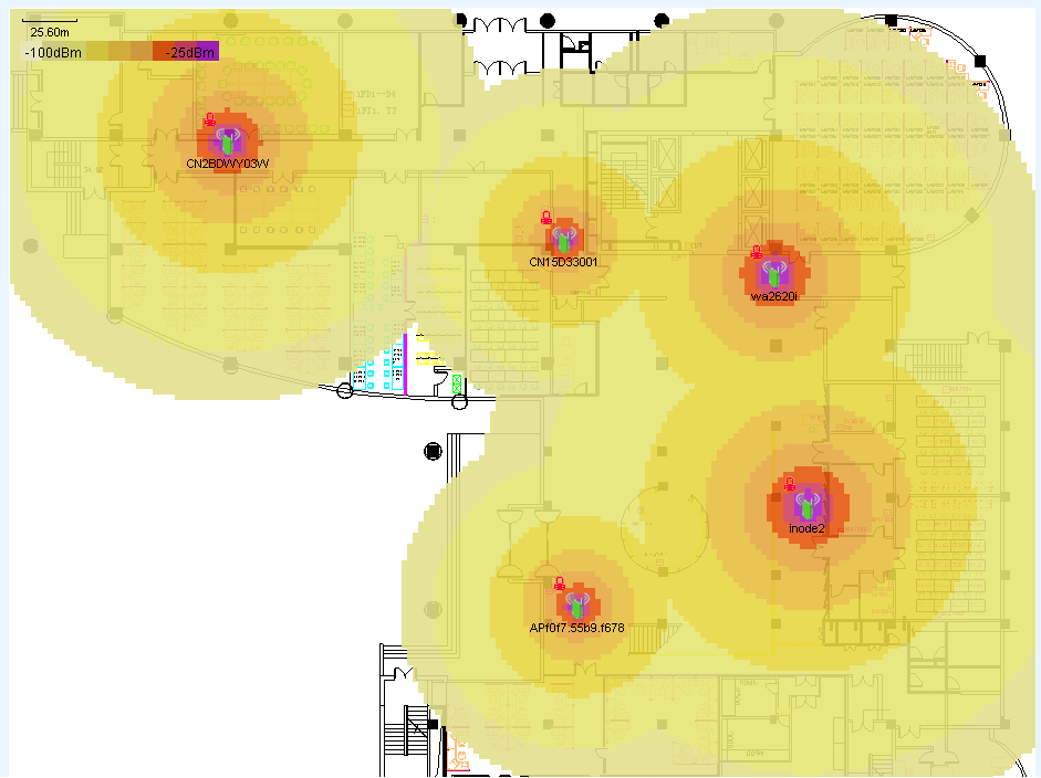
Displaying transmission rates on the map
You can display transmission rates on the map in the following way:
Right-click a blank area, and select one of the following from the shortcut menu:
· Show Signal Coverage > By Rate > 2.4GHz
· Show Signal Coverage > By Rate > 5GHz
The map displays the signal coverage area of each AP. Click to view transmission rates, as shown in Figure 75.
Figure 75 Displaying transmission rates (2.4 GHz)
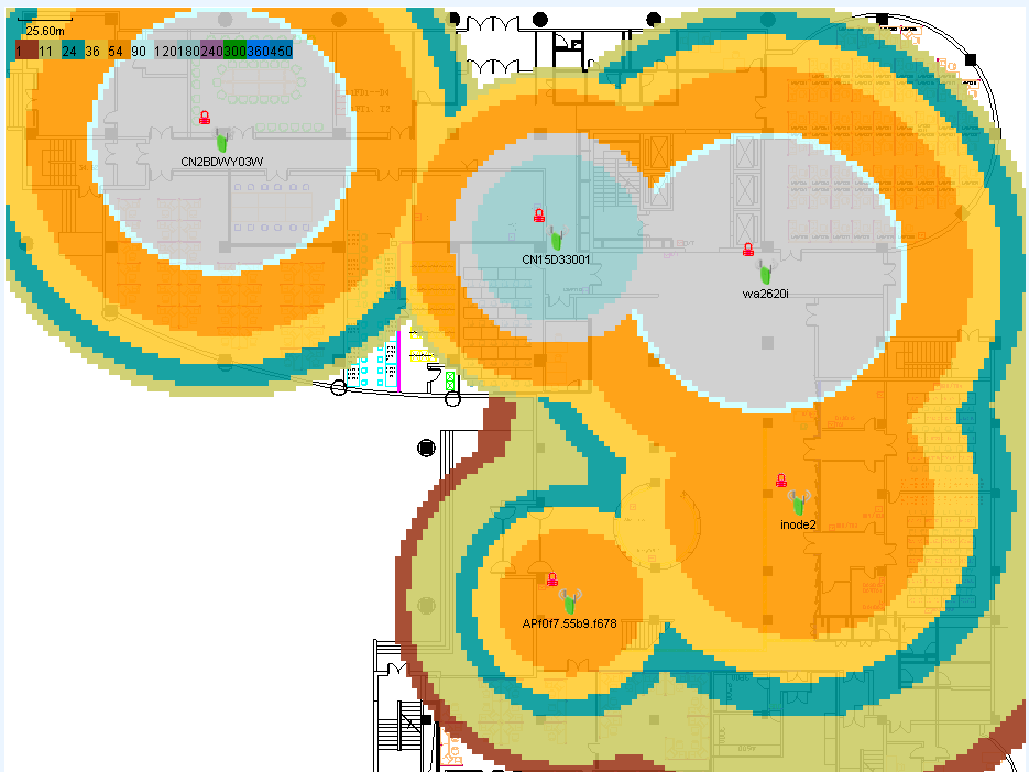
Displaying AP operating channels on the map
You can display AP operating channels on the map in the following way:
Right-click on a blank area, and select one of the following from the shortcut menu:
· Show Signal Coverage > By Channel > 2.4GHz
· Show Signal Coverage > By Channel > 5GHz
· Show Signal Coverage > By Channel > Single Channel
If you select Single Channel, the Set Channel window opens. Enter a channel number, and click OK.
The map displays the signal coverage area of each AP. Click to view AP operating channels, as shown in Figure 76.
Figure 76 Displaying operating channels (2.4 GHz)
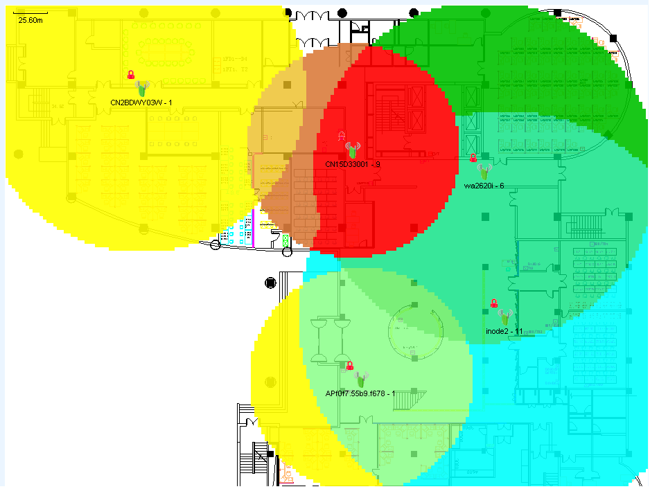
Displaying APs using a specific SSID on the map
You can display APs using a specific SSID on the map in the following way:
Right-click on a blank area, and select one of the following from the shortcut menu:
· Show Signal Coverage > By SSID > 2.4GHz
· Show Signal Coverage > By SSID > 5GHz
Select an SSID from the SSID List in the window that opens.
The map displays the signal coverage area of APs that use the selected SSID. Click to view the signal strength, as shown in Figure 77.
Figure 77 Displaying APs using a specific SSID (2.4 GHz)
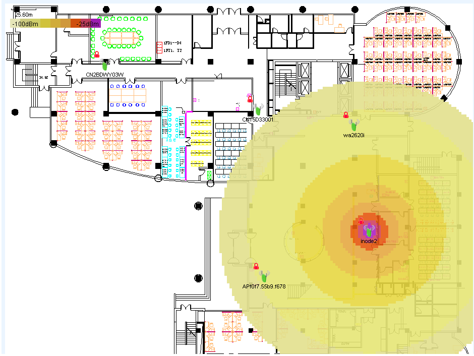
Refreshing the RF heat map
Click the Refresh icon on the toolbar.
Hiding the signal coverage area
Right-click a blank area, and select Hide Signal Cover Area from the shortcut menu.
Setting colors
You can set colors for different signal strengths, rates, and channels for signal coverage predication maps.
Setting the color for a signal strength
1. Right-click a blank area, and select Color Settings > Set Signal Strength Color from the shortcut menu.
The window for setting signal strength colors opens, displaying the signal strength values and their associated colors, as shown in Figure 78.
Figure 78 Setting the signal strength color
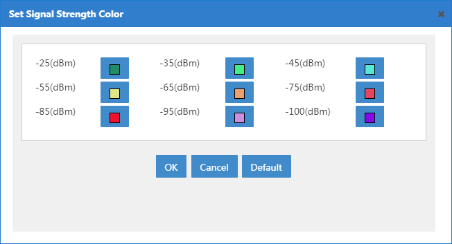
2. Click the color block to be modified.
The window for modifying the color opens.
3. Select a color.
4. Click OK.
Setting the color for a rate
1. Right-click a blank area, and select Color Settings > Set Rate Color from the shortcut menu.
The window for setting rate colors opens, displaying the rate values and their associated colors, as shown in Figure 79.
Figure 79 Setting the rate color
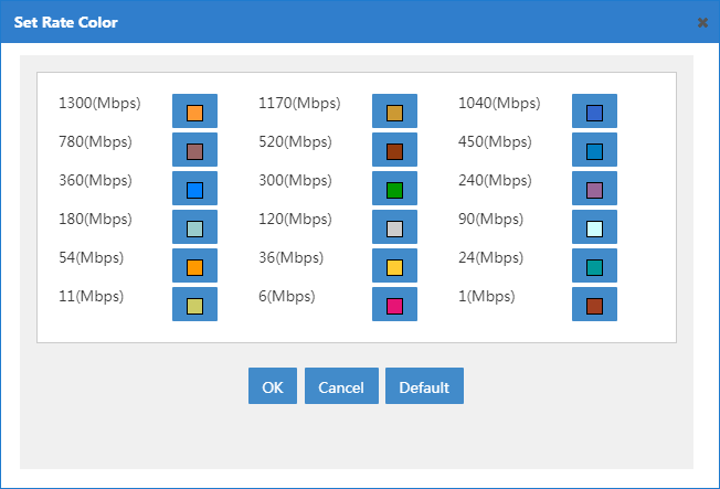
2. Click the color block to be modified.
The window for modifying colors opens.
3. Select a color.
4. Click OK.
Setting the color for a channel
1. Right-click a blank area, and select Color Settings > Set Channel Color from the shortcut menu.
The window for setting channel colors opens, displaying the channel values and their associated colors, as shown in Figure 80.
Figure 80 Setting the channel color
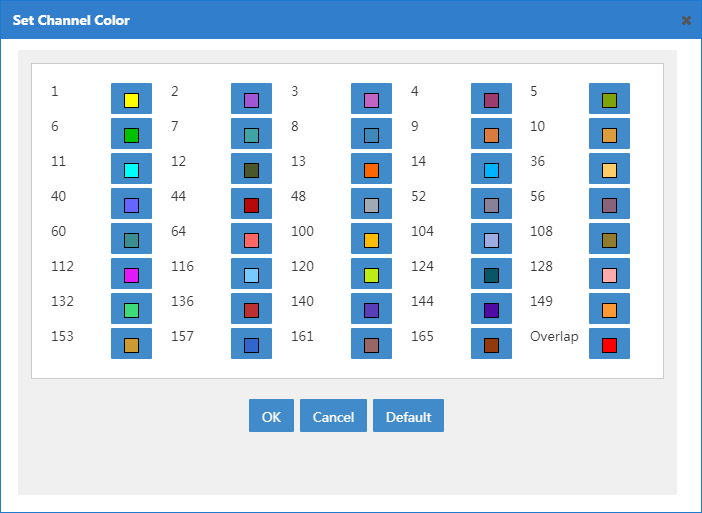
2. Click the color block to be modified.
The window for modifying colors opens.
3. Select a color.
4. Click OK.
Configuring signal coverage parameters
WSM allows you to configure signal receive sensitivity and power usage for a location view.
· Receive sensitivity—Minimum AP signal strength in a location view. WSM does not display signals that are weaker than the value specified by the Show Signal Coverage parameter for both APs and virtual APs in the location view.
· Power Usage (%)—Power usage in a band for APs and virtual APs in a location view.
To configure signal coverage parameters:
1. On the tool bar of the topology, click the Signal Coverage Parameters icon ![]() .
.
The Signal Coverage Parameters dialog box opens.
2. Configure the following parameters:
¡ Cut Off Signal—Enter a value or move the scroll bar to set the minimum signal strength to display in the location view.
¡ Power Usage (%)-2.4 GHz—Enter a power usage value for the 2.4 GHz band in the location view.
¡ Power Usage (%)-5 GHz—Enter a power usage value for the 5 GHz band in the location view.
3. Click OK.
Managing spectrum guard
To use spectrum guard, first enable spectrum analysis. Spectrum analysis evaluates channel quality and detects interferences on monitored channels. The following interferences can be detected:
· Microwave ovens
· Bluetooth
· Fixed-frequency (video)
· Cordless phone
· Microsoft Xbox
Spectrum guard module provides the following:
· Automatically switches the working channel of a radio, based on channel quality, to make sure the radio is always operating on the optimum channel.
· Summarizes and displays the spectrum analysis data in graphs and charts. You can adjust the configurations or the WLAN layout to obtain better network performance.
This chapter describes how to configure and use the spectrum guard module.
Setting the operating mode of an AP
To use spectrum analysis, make sure the AP operates in hybrid or monitor mode. If the AP operates in normal mode, the radio detects only the operating channel.
To set the operating mode of an AP:
1. Click the Service tab.
2. From the navigation tree, select WLAN Manager > Resource Management > Fit APs.
The Fit AP List page opens.
3. Click the label of the AP.
The fit AP details page opens.
4. In the Action menu located on the right
of the page, click the Modify AP Template icon ![]() .
.
The Modify AP Template page opens.
5. Set the operating mode to Hybrid or Monitor.
|
|
NOTE: · To switch between the hybrid mode and monitor mode, first change the operating mode to normal mode. · To view the Signal Strength by SSID statistics, set the AP to operate in monitor mode. |
Configuring spectrum analysis
To configure spectrum analysis on a Comware-based AC, make sure the AC has registered the rfp license.
Configure spectrum analysis for the 2.4 GHz band and 5 GHz band separately.
To configure spectrum analysis:
1. Click the Service tab.
2. From the navigation tree, select WLAN Manager > Spectrum Guard.
The Spectrum Guard page opens.
3. Select the AC from the Device Configuration list.
4. Click the Spectrum Analysis Configuration link.
The Spectrum Analysis Configuration page for the 2.4 GHz band opens.
5. Configure the following parameters for the 2.4 GHz band:
¡ Spectrum Analysis—Enable spectrum analysis, and then the AP can perform spectrum analysis for the 2.4 GHz band.
¡ Select interferences—Select the type of devices to detect from the following options:
- Microwave Oven
- Bluetooth
- Fixed-Frequency
- Cordless Phone
- Microsoft Xbox
¡ Interference Alarm—Enable or disable alarm generation for interferences. After you enable interference alarm, the AC sends traps to IMC when the radio detects interferences.
¡ Select interferences—Select the type of interference devices for which alarms are generated. The AC sends traps to IMC only when the radio detects the specified interferences. Select from the following options:
- Microwave Oven
- Bluetooth
- Fixed Frequency
- Fixed Frequency (Video)
- Cordless Phone
- Microsoft Xbox
This field is available only when you enable the interference alarm.
¡ Channel Quality Alarm—Enable or disable channel quality alarms. After you enable channel quality alarms, the AC sends traps to IMC when the channel quality is below the specified threshold.
¡ Channel Quality Alarm Threshold—Enter the trigger value of channel quality alarms, in the range of 1 to 100. This field is available only when you enable the channel quality alarm.
¡ Automatic Channel Selection—Enable or disable automatic channel selection. After you enable automatic channel selection, channel adjustment is triggered on the AC when the quality of the current operating channel is below the specified threshold.
When the quality of the current channel drops below the threshold, the AC selects a new channel for the AP. However, the AP does not use the new channel until the channel quality difference between the new and old channels exceeds the tolerance level. For more information, see the related device manual.
Automatic channel switchover can only be performed if the radio adopts the auto mode. For more information, see the related device manual.
¡ Sensitivity Level—Select the sensitivity level for automatic channel selection when interference is detected. Options are Low, Medium, and High. The higher the sensitivity level, the higher the channel switchover frequency.
6. Click OK.
Click OK to save the configuration before switching to another page.
7. Click the 5GHz tab to configure parameters for the 5 GHz band.
The configuration for the 5 GHz band is the same as the configuration for the 2.4 GHz band, except the interference types that can be detected.
8. Click OK.
Configuring radios
WSM allows you to configure the following on the radio configuration page:
· Enabling and disabling spectrum analysis
· Enabling and disabling FFT monitoring
· Configuring channels for monitoring.
· View spectrum analysis data. For more information, see "Managing spectrum analysis monitor."
To scan channels, detect channel qualities, and detect interferences operating in each channel, you must first enable spectrum analysis for radios.
To view FFT, FFT duty cycle, and swept spectrogram data, you must first enable FFT monitoring.
For the 2.4 GHz band, a radio can only monitor channels 1 to 14.
For the 5 GHz band, a radio monitors channels 149 to 165 by default. You can change the monitored channels for the 5 GHz band.
Viewing the radio list
1. Click the Service tab.
2. From the navigation tree, select WLAN Manager > Spectrum Guard > Radio Config.
The Radio List displays all radios.
Radio List
¡ AP Label—Label of the AP to which the radio belongs. Click the label of the AP to view details.
¡ AP SN—Serial number of the AP to which the radio belongs.
¡ AP Model—Model of the AP to which the radio belongs.
¡ Radio ID—ID of the radio assigned by the AP.
¡ Radio Type—Options are:
- 802.11a
- 802.11b
- 802.11g
- 802.11an
- 802.11gn
¡ Analysis Status—Spectrum analysis status of the radio.
¡ FFT State—FFT enable status of the radio.
¡ Channels to Monitor—Channels monitored by the radio. For the 2.4 GHz band, the radio can monitor channels 1 to 14. For the 5 GHz band, the radio can monitor channels 36 to 64, 100 to 140, and 149 to 165.
¡ Location—Name of the location view of the AP to which the radio belongs. Click the name of the location view to view the topology.
¡ AC—Name of the AC with which the AP (to which the radio belongs) is associated. Click the name of the AC to view its details.
¡ Operation—Click the Operation icon ![]() to view the spectrum analysis information that the radio detected.
to view the spectrum analysis information that the radio detected.
From the ![]() Operation menu, you can select Spectrum
Analysis Monitor and Spectrum Analysis Monitor History.
Operation menu, you can select Spectrum
Analysis Monitor and Spectrum Analysis Monitor History.
If the Radio List contains enough entries, the following navigational aids are displayed.
· Click the Next Page
icon ![]() to page
forward in the Radio List.
to page
forward in the Radio List.
· Click the Last Page
icon ![]() to page
forward to the end of the Radio List.
to page
forward to the end of the Radio List.
· Click the Previous Page
icon ![]() to page
backward in the Radio List.
to page
backward in the Radio List.
· Click the First Page
icon ![]() to page
backward to the front of the Radio List.
to page
backward to the front of the Radio List.
Click 8, 15, 50, 100, or 200 on the upper right of the Radio List to specify the number of items you want to display on each page.
|
|
NOTE: You can sort the Radio List by every field except the Operation field. Click the column label to sort the list by the selected field. The column label allows you to toggle between the various sort options specific to each field. |
Querying radios
WSM provides basic query and advanced query. Basic query criteria include several key parameters for quick searches. Advanced query offers various query criteria for precise matching.
To query radios:
1. Click the Service tab.
2. From the navigation tree, select WLAN Manager > Spectrum Guard > Radio Config.
The Radio Config page opens.
3. Perform a basic query:
a. Enter the device label (case-insensitive) of the AP. WSM supports fuzzy matching for this field.
b. Click the Query icon
![]() . The Radio Config page displays all APs matching the query
criteria.
. The Radio Config page displays all APs matching the query
criteria.
4. Clear the Query
field, and click the Query icon ![]() to display all APs.
to display all APs.
5. Perform an advanced query:
a. Click the Expand
icon ![]() next to the Query field to expand the Query area. Click it again to hide the Query area.
next to the Query field to expand the Query area. Click it again to hide the Query area.
b. Enter or select one or more of the following query criteria:
¡ AP Label—Enter the AP label. WSM supports fuzzy matching for this field.
¡ Serial Number—Enter the AP serial number. WSM supports fuzzy matching for this field.
¡ AP Model—Enter the AP model. WSM supports fuzzy matching for this field.
¡ Radio Type—Enter the radio type. Options are:
- All
- 802.11a
- 802.11b
- 802.11g
- 802.11an
- 802.11gn
¡ Analysis Status—Select the spectrum analysis status of the radio. Options are All, Enable, and Disable.
¡ FFT State—Select the FFT status of the radio. Options are All, Enable, and Disable.
¡ Location—Select location in one of the following ways:
- Enter the location view of the AP that uses the radio.
- Click the field, and select the location view from the list that appears.
¡ AC—Select an AC. All radios of the APs managed by the AC are queried.
An empty field or a field that is set to All does not serve as a query criterion.
c. Click Query.
The Radio List displays all radios matching the query criteria.
d. Click Reset to clear the query criteria and display all radios.
Enabling spectrum analysis/FFT monitoring
To scan interferences, monitor AP channel qualities, or perform other operations on a radio, first enable spectrum analysis for the radio. To monitor, record, or save the data of FFT, FFT Duty Cycle, or Swept Spectrogram, first you must enable FFT monitoring.
To enable spectrum analysis or FFT monitoring:
1. Click the Service tab.
2. From the navigation tree, select WLAN Manager > Spectrum Guard > Radio Config.
The Radio Config page opens.
3. Select APs for which you want to enable spectrum analysis or FFT monitoring from the Radio List.
4. Click Enable Analysis or Enable FFT.
The Result List page shows the operation result for each radio.
5. Click Back to return to the Radio Config page.
Disabling spectrum analysis/FFT monitoring
1. Click the Service tab.
2. From the navigation tree, select WLAN Manager > Spectrum Guard > Radio Config.
The Radio Config page opens.
3. From the Radio List, select APs for which you want to disable spectrum analysis/FFT monitoring.
4. Click Disable Analysis or Disable FFT.
The Result List page shows the operation result of each radio.
5. Click Back to return to the Radio Config page.
Configuring channels to be monitored
For the 5 GHz band, you can change the channels that radios monitor.
To configure channels to be monitored:
1. Click the Service tab.
2. From the navigation tree, select WLAN Manager > Spectrum Guard > Radio Config.
The Radio Config page opens.
3. From the Radio List, select radios for which you want to configure channel monitoring.
When multiple radios are selected, make sure the radios are operating at the same frequency.
4. Click Monitor Channels.
The Monitor Channels window opens.
5. Select the channel range.
Applicable channel ranges vary by regions.
6. Click OK.
Viewing current interferences
You can view, query, and locate current interferences on the WLAN to eliminate the interferences. The following interferences can be detected by AC:
· Microwave ovens.
· Bluetooth.
· Fixed frequency.
· Fixed frequency video devices.
· Cordless phone.
· Microsoft Xbox.
Viewing the current interference list
1. Click the Service tab.
2. From the navigation tree, select WLAN Manager > Spectrum Guard > Interferences.
The Interferences page opens.
3. Click Synchronize.
4. Enter the Interferences page again after synchronization.
The Current Interference List displays all interferences.
Current Interference List
¡ Interference Type—Type of the interference. Interference types follow:
- Microwave Oven
- Bluetooth
- Fixed-Frequency
- Fixed-Frequency (Video)
- Cordless Phone
- Microsoft Xbox
¡ Sensitivity—Severity level of the interference, in the range of 0 to 100. A higher value indicates a higher interference.
¡ RSSI—Signal strength of the interference.
¡ Duty Cycle (%)—Duty cycle of the interference. Duty cycle is the time when the interference device was active. You can view the duty cycle on the device.
¡ Affected Channel—Channel affected by the interference.
¡ AP Label—Label of the AP to which the radio (that detected the interference) belongs. Click the label of the AP to view details.
¡ Location—Location view to which the interference belongs. WSM locates the interference to the location view of the AP that detected the interference. Click the location view name to view the location view topology.
¡ Detected Time—Time when the AP detected the interference.
¡ Operation—Click the Operation icon ![]() for the interference to display the operation menu.
for the interference to display the operation menu.
From the Operation menu, you can select View Topology to locate the interference in the topology.
If the Current Interference List contains enough entries, the following navigational aids are displayed.
· Click the Next Page
icon ![]() to page
forward in the Current Interference List.
to page
forward in the Current Interference List.
· Click the Last Page
icon ![]() to page
forward to the end of the Current Interference List.
to page
forward to the end of the Current Interference List.
· Click the Previous Page
icon ![]() to page
backward in the Current Interference List.
to page
backward in the Current Interference List.
· Click the First Page
icon ![]() to page
backward to the front of the Current Interference List.
to page
backward to the front of the Current Interference List.
Click 8, 15, 50, 100, or 200 at the upper right of the Current Interference List to specify the number of items you want to display on each page.
|
|
NOTE: You can sort the Current Interference List by every field except the Operation field. Click the column label to sort the list by the selected field. The column label allows you to toggle between the various sort options specific to each field. |
Querying current interferences
WSM provides basic query and advanced query. Basic query criteria include several key parameters for quick searches. Advanced query offers various query criteria for precise matching.
To query current interferences:
1. Click the Service tab.
2. From the navigation tree, select WLAN Manager > Spectrum Guard > Interferences.
The Interferences page opens.
3. Perform a basic query:
a. Enter the device label (case-insensitive) of the AP. WSM supports fuzzy matching for this field.
b. Click the Query icon
![]() . The Interference List displays all interferences matching the
query criteria.
. The Interference List displays all interferences matching the
query criteria.
4. Clear the Query
field, and click the Query icon ![]() to display all interferences.
to display all interferences.
5. Perform an advanced query:
a. Click the Expand
icon ![]() next to the Query field to expand the Query area. Click it again to hide the Query area.
next to the Query field to expand the Query area. Click it again to hide the Query area.
b. Enter or select one or more of the following query criteria:
¡ AP Label—Enter the AP label. WSM supports fuzzy matching for this field
¡ Affected Channel—Enter the affected channel. All interferences on this channel are queried WSM does not support fuzzy matching for this field.
¡ Interference Type—Select the type of the interferences. Options are:
- Unlimited
- Microwave Oven
- Bluetooth
- Fixed-Frequency (Video)
- Cordless Phone
- Microsoft Xbox
¡ Location—Enter the location of the interferences. Or click the field and select the location of the interference from the list that appears.
An empty field or a field that is set to Unlimited does not serve as a query criterion.
c. Click Query.
The Current Interference List displays all interferences matching the query criteria.
d. Click Reset to clear the query criteria and display all interferences.
Locating an interference
This function allows you to locate interferences in the topology view of APs that detected the interferences.
To locate an interference:
1. Click the Service tab.
2. From the navigation tree, select WLAN Manager > Spectrum Guard > Interferences.
The Interferences page opens.
3. Click the Operation
icon ![]() for the
target interference, and select View Topology from
the shortcut menu.
for the
target interference, and select View Topology from
the shortcut menu.
The topology window opens, and the interference is circled with a red box in the location view.
Managing interference history
WSM allows you to view interference history, such as interference type, sensitivity, detected time, and location.
Viewing interference history
1. Click the Service tab.
2. From the navigation tree, select WLAN Manager > Spectrum Guard > Interfere Data.
The Interfere Data page opens.
Interference History List
¡ Interference Type—Type of the interference. Options are:
- Microwave Oven
- Bluetooth
- Cordless Phone
- Microsoft Xbox
¡ Sensitivity—Severity level of the interference, in the range of 0 to 100. A higher value indicates a higher interference.
¡ RSSI—Signal strength of the interference.
¡ Duty Cycle (%)—Duty cycle of the interference. Duty cycle is the time when the interference device was active. You can view the duty cycle on the device.
¡ Affected Channel—Channel affected by the interference.
¡ AP Label—Label of the AP to which the radio (that detected the interference) belongs.
¡ Location—Location view to which the interference belongs.
¡ Detected Time—Time when the AP detected the interference.
¡ Last Disappeared—Time when the interference disappeared.
If the Interference History List contains enough entries, the following navigational aids are displayed.
· Click the Next Page
icon![]() to page
forward in the Interference History List.
to page
forward in the Interference History List.
· Click the Last Page
icon ![]() to page
forward to the end of the Interference History List.
to page
forward to the end of the Interference History List.
· Click the Previous Page
icon ![]() to page
backward in the Interference History List.
to page
backward in the Interference History List.
· Click the First Page
icon ![]() to page
backward to the front of the Interference History List.
to page
backward to the front of the Interference History List.
Click 8, 15, 50, 100, or 200 at the upper right of the Interference History List to specify the number of items you want to display on each page.
Querying interference history
WSM provides basic query and advanced query. Basic query criteria include several key parameters for quick searches. Advanced query offers various query criteria for precise matching.
To query interference history:
1. Click the Service tab.
2. From the navigation tree, select WLAN Manager > Spectrum Guard > Interfere Data.
The Interfere Data page opens.
3. Perform a basic query:
a. Enter the device label (case-insensitive) of the AP. WSM supports fuzzy matching for this field.
b. Click the Query icon
![]() . The Interfere Data page displays all interference data
matching the query criteria.
. The Interfere Data page displays all interference data
matching the query criteria.
4. Clear the Query
field, and click the Query icon ![]() to display all interference
data.
to display all interference
data.
5. Perform an advanced query:
a. Click the Expand
icon ![]() next to the Query field to expand the Query area. Click it again to hide the Query area.
next to the Query field to expand the Query area. Click it again to hide the Query area.
b. Enter or select one or more of the following query criteria:
¡ AP Label—Enter the label of the AP. WSM supports fuzzy matching for this field.
¡ Affected Channel—Enter the affected channel. All interferences on this channel are queried WSM does not support fuzzy matching for this field.
¡ Interference Type—Select the type of the interference. Options are:
- Unlimited
- Microwave Oven
- Bluetooth
- Fixed-Frequency (Video)
- Cordless Phone
- Microsoft Xbox
An empty field or a field that is set to Unlimited does not serve as a query criterion.
c. Click Query.
The Interferences History List displays all interference history matching the query criteria.
d. Click Reset to clear the query criteria and display all interference history.
Managing AP channel quality
AP channel quality refers to the quality of a channel. Higher channel quality indicates fewer interferences, and better WLAN access for clients on the channel.
Viewing the AP channel quality list
1. Click the Service tab.
2. From the navigation tree, select WLAN Manager > Spectrum Guard > Channel Quality.
The Channel Quality page opens.
3. Click Synchronize.
AP Channel Quality List
¡ AP Label—Label of the AP that monitors the channel. Click the label of the AP to view its details.
¡ Radio ID—ID of the AP's radio that monitors the channel.
¡ Monitored Channel—Channel that the AP monitors.
¡ Average Quality—Average score of the channel assessment, in the range of 1 to 100. A greater value indicates a better quality.
¡ Worst Quality—Lowest quality score of the channel, in the range of 1 to 100.
¡ Interference Count—Number of the interferences on the channel.
¡ Noise Floor—Noise floor of the radio in dBm. Noise floor affects channel quality and changes with the temperature.
If the AP Channel Quality List contains enough entries, the following navigational aids are displayed.
· Click the Next Page
icon ![]() to page
forward in the AP Channel Quality List.
to page
forward in the AP Channel Quality List.
· Click the Last Page
icon ![]() to page
forward to the end of the AP Channel Quality List.
to page
forward to the end of the AP Channel Quality List.
· Click the Previous Page
icon ![]() to page
backward in the AP Channel Quality List.
to page
backward in the AP Channel Quality List.
· Click the First Page
icon ![]() to page
backward to the front of the AP Channel Quality List.
to page
backward to the front of the AP Channel Quality List.
Click 8, 15, 50, 100, or 200 at the upper right of the AP Channel Quality List to specify the number of items you want to display on each page.
Querying AP channel quality
WSM provides basic query and advanced query. Basic query criteria include several key parameters for quick searches. Advanced query offers various query criteria for precise matching.
To query AP channel quality:
1. Click the Service tab.
2. From the navigation tree, select WLAN Manager > Spectrum Guard > Channel Quality.
The Channel Quality page opens.
3. Perform a basic query:
a. Enter the device label (case-insensitive) of the AP. WSM supports fuzzy matching for this field.
b. Click the Query icon
![]() . The Channel Quality page displays all channels matching the
query criteria.
. The Channel Quality page displays all channels matching the
query criteria.
c. Clear the Query
field, and click the Query icon ![]() to display all channels.
to display all channels.
4. Perform an advanced query:
a. Click the Expand
icon ![]() next to the Query field to expand the Query area. Click it again to hide the Query area.
next to the Query field to expand the Query area. Click it again to hide the Query area.
b. Enter one or more of the following query criteria:
¡ AP Label—Enter the label of the AP that uses the radio monitoring the channel. WSM supports fuzzy matching for this field.
¡ Channel—Enter the number of the channel. WSM does not support fuzzy matching for this field.
An empty field does not serve as a query criterion.
c. Click Query.
The AP Channel Quality List displays all AP channel qualities matching the query criteria.
d. Click Reset to clear the query criteria and display all AP channel qualities.
Managing spectrum analysis monitor
Spectrum analysis monitor collects statistics and draws trend graphs and bar charts for channel usage, channel quality, interference signal strength, FFT, swept spectrogram, and signal strength by SSID.
Viewing spectrum analysis monitor data
1. Click the Service tab.
2. From the navigation tree, select WLAN Manager > Spectrum Guard > Radio Config.
The Radio Config page opens.
3. Click the Operation
icon![]() for the
interference, and click the Spectrum Analysis Monitor tab.
for the
interference, and click the Spectrum Analysis Monitor tab.
The Spectrum Analysis Monitor window opens.
4. Configure the following monitor parameters:
¡ Statistics—Select the type of spectrum analysis monitor information. Options are:
- Channel Usage
- Channel Usage Trend
- Channel Quality
- Channel Quality Trend
- Interference Signal Strength
- FFT
- FFT Duty Cycle
- Swept Spectrogram
- Signal Strength by SSID
¡ Radio ID—Select the radio used to monitor channels.
Figure 81 shows the channel usage bar chart.
Figure 81 Channel Usage bar chart
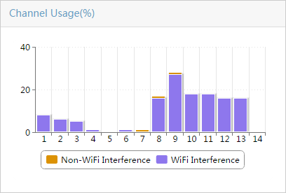
Figure 82 shows the channel usage trend graph.
Figure 82 Channel Usage Trend graph
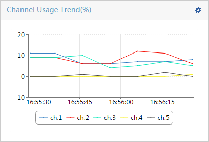
To specify channels:
a. At the upper right of the graph, click the Select Channel icon ![]() .
.
The Select Channel window opens.
b. To specify a channel to monitor, select the
channel and click ![]() . To specify a channel to stop monitoring, select the channel and
click
. To specify a channel to stop monitoring, select the channel and
click ![]() . To monitor all channels, click
. To monitor all channels, click ![]() . To stop monitoring all channels, click
. To stop monitoring all channels, click ![]() .
.
c. Click OK.
Figure 83 shows the channel quality bar chart.
Figure 83 Channel Quality bar chart
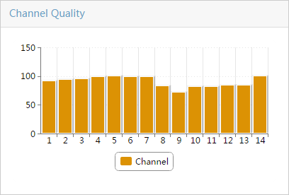
Figure 84 shows the channel quality trend graph.
Figure 84 Channel Quality Trend graph
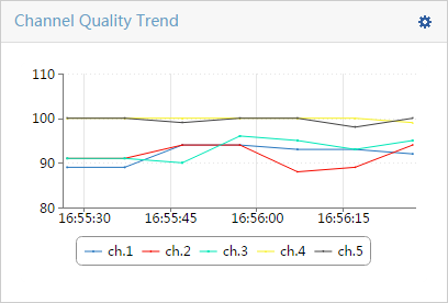
To specify channels:
a. Click the Select
Channel icon ![]() .
.
The Select Channel window opens.
b. To specify a channel to monitor, select the
channel and click ![]() . To specify a channel to stop monitoring, select the channel and
click
. To specify a channel to stop monitoring, select the channel and
click ![]() . To monitor all channels, click
. To monitor all channels, click ![]() . To stop
monitoring all channels, click
. To stop
monitoring all channels, click ![]() .
.
c. Click OK.
Figure 85 shows the interference signal strength graph.
Figure 85 Interference Signal Strength graph
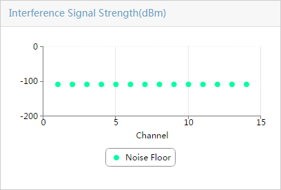
Figure 86 shows the FFT monitor trend graph.
Figure 86 FFT monitor trend graph
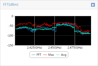
· To record and export the monitor data of FFT, see "Recording and exporting spectrum analysis monitor data."
¡ FFT—Interference signal strength on the frequency.
¡ Max—Maximum interference signal strength on the frequency.
¡ Avg—Average interference signal strength on the frequency.
Figure 87 shows the FFT duty cycle trend graph.
Figure 87 FFT Duty Cycle trend graph
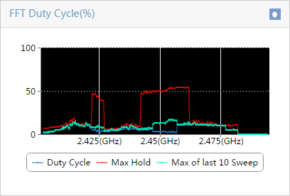
To record and export the monitor data of FFT Duty Cycle, see "Recording and exporting spectrum analysis monitor data."
¡ Duty Cycle—Duty cycle of interference signals on the frequency.
¡ Max Hold—Maximum duty cycle of interference signals on the frequency.
¡ Max of last 10 Sweep—Maximum duty cycle of interference signals on the frequency over the last 10 sweeps.
Figure 88 shows the swept spectrogram graph.
Figure 88 Swept Spectrogram graph
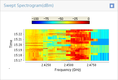
To record and export the monitor data of FFT, see "Recording and exporting spectrum analysis monitor data."
Figure 89 shows the signal strength by SSID graph.
Figure 89 Signal Strength by SSID (dBm)
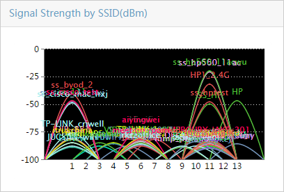
5. Click Monitor.
WSM collects and displays monitor statistics in graphs and charts.
6. Click Stop Monitor.
The graphs and charts display the last refreshed monitor data.
Recording and exporting spectrum analysis monitor data
1. Click the Service tab.
2. From the navigation tree, select WLAN Manager > Spectrum Guard > Radio Config.
The Radio Config page opens.
3. Click the Operation
icon ![]() for the
interference, and click the Spectrum Analysis Monitor
tab.
for the
interference, and click the Spectrum Analysis Monitor
tab.
The Spectrum Analysis Monitor window opens.
4. Configure the following parameters:
¡ Statistics—Select the type of spectrum analysis monitor information to record and export. Options are FFT, FFT Cycle, and Swept Spectrogram.
¡ Radio ID—Select the ID of the radio for spectrum analysis monitoring.
5. Click Monitor.
WSM collects and displays monitor statistics in graphs and charts.
6. At the upper right of the graph, click the Start Recording icon ![]() .
.
7. At the upper right of the graph, click the Stop Recording icon ![]() .
.
8. At the upper right of the graph, click the Save Recordings icon ![]() .
.
The Download Exported Template File dialog box opens.
|
|
NOTE: If the Internet Explorer browser is used, select Tools > Internet Options > Security > Internet > Custom level > Downloads, and enable Automatic Prompting for file downloads before exporting files. |
9. Click Export Result.
The Download Exported Template File dialog box opens.
10. Click Save.
11. Click OK.
Viewing spectrum analysis monitor history
1. Click the Service tab.
2. From the navigation tree, select WLAN Manager > Spectrum Guard.
The Spectrum Guard page opens.
3. On the AP Spectrum Analysis list, click the Spectrum Analysis Monitor History link.
The Spectrum Analysis Monitor History window opens.
4. Configure the following parameters:
¡ Statistics—Select the type of the spectrum analysis monitor information.
¡ Select File—For Select File, do one of the following:
- Enter the absolute path of the file.
- Click Browse to open the file.
¡ Start Time—For Start Time, do one of the following:
- Enter the start time of the history data, in the YYYY-MM-DD hh:mm format.
- Click the Calendar icon ![]() to
select a start time.
to
select a start time.
¡ Stop Time—For Stop Time, do one of the following:
- Enter the end time of the history data, in the YYYY-MM-DD hh:mm format.
- Click the Calendar icon ![]() to select an end time.
to select an end time.
If you do not specify either the start time or the stop time, the system displays all data of the file.
5. Click Query.
The graphs display the data of the specified time period.
6. Click Close.
Managing wireless locating
WSM wireless locating enables you to locate wireless clients (WiFi mobile phones, PDAs, terminals installed with the iNode client, and laptops) and APs in 802.11 networks.
Overview
Locating modes
WSM supports Location Aware locating, BLE locating, converged Location Aware and BLE locating, X-Share locating, AP-based locating, and GIS locating.
Priorities of locations obtained through realtime locating (including BLE locating, Location Aware locating, and converged Location Aware and BLE locating), X-Share locating, and AP-based locating are in descending order. If all the above locating methods fail to locate a client, WSM assumes that the client is near the associated AP.
Location Aware locating
Location Aware locating uses Round Trip Time (RTT) to locate clients in real time.
Only APs that support Location Aware locating can be used for Location Aware locating.
In addition to locating clients, Location Aware locating supports the following functions:
· Tracking clients in the location view in real time.
· Displaying a client track by using a line in the location view.
· Dynamically displaying a client track in the location view.
· Allowing you to view the heat map for each client during the specified period in location view.
· Allowing you to draw a digital fence to collect locations in an area.
BLE locating
BLE locating determines the location of a client by triangulating the relative signal strength detected by beacons in the WLAN in real time. Compared with Location Aware locating, BLE locating has lower cost and is more precise.
You need to deploy beacons before performing BLE locating.
In addition to locating clients, BLE locating supports the following functions:
· Tracking clients in the location view in real time.
· Displaying a client track by using a line in the location view.
· Dynamically displaying a client track in the location view.
· Allowing you to view the heat map for each client during the specified period in location view.
X-Share locating
Only APs that support X-Share antennas can be used for X-Share locating. To use X-Share locating, put the X-Share antenna icon in the correct place in the location view according to the actual situation. The AP can obtain the rough location of a client. If the X-share locating fails, WSM assumes that the client is near the X-Share antenna.
AP-based wireless locating
In AP-based wireless locating, APs scan wireless signals to locate wireless clients (including rogue clients) and rogue APs. For example, a sampling AP estimates the distance between a client and each AP. Then, WSM can obtain the rough location of the client and display it in the location view.
GIS locating
GIS locating is performed in GIS view. Before performing GIS locating, add location views to GIS view, and set the longitude and latitude. Then WSM can locate fit APs, fat APs, or clients in GIS view according to their location views.
By default, Map World is loaded in GIS view. Make sure IMC can be connected to the Internet so that Map world can be loaded.
GIS locating is typically applied in enterprises that have multiples branches.
Terminology
· Received Signal Strength Indicator—RSSI indicates the received signal strength. WSM uses RSSI to implement wireless locating.
· Location view—A view defined in WSM for wireless locating and RF management. You must create a location view and set the background picture, and scale in the location view before using the wireless locating function.
· GIS view—A view defined in WSM for GIS locating.
· Background picture—A background picture reflects the actual networking environment on the topology. To ensure locating performance, set a correct scale for the background picture and place sampling APs and sampling points on a correct position on the background picture.
Configuring a location view
This configuration is the basis of wireless locating.
Creating a location view
For information about creating a location view, see "Managing location views."
Setting a background picture
1. Click the Service tab.
2. From the navigation tree, select WLAN Manager > Wireless Topology.
The wireless topology window opens.
3. From the left navigation tree, enter the location view for which you want to set the background picture.
4. On the toolbar at the top of the topology page,
click the Add background icon![]() .
.
The Topo Background-Picture Setting window opens.
5. Select a background picture:
a. You can use a local picture or a picture from the gallery on the IMC database.
To use a local picture—Select User Upload Picture and click Browse to select a local picture. The picture's name can contain only letters, digits, hyphens (-), underscores (_), and spaces. For information about other restrictions for the picture, see the prompt information.
To use a picture from the gallery on the IMC database—Select a picture from the gallery preview area and click Select Picture. By default, the preview area displays the first background picture according to shown in alphabetical order by name.
b. Click Set.
c. Click Close.
6. (Optional) Adjust the location and size of the background picture:
a. Right-click on a blank area, and select Adjust Background > Manual Adjust from the shortcut menu.
You are in background picture adjustment mode.
b. Right-click on a blank area, and select Exit Adjust Background from the shortcut menu to exit the background picture adjustment mode.
Setting a scale
The scale of a topology is the ratio of a distance on the background picture to the corresponding actual distance.
To set a scale:
1. Click the Service tab.
2. From the navigation tree, select WLAN Manager > Wireless Topology.
The wireless device topology window opens.
3. From the left navigation tree, enter the location view for which you want to set the scale.
4. Click the Set Scale
icon ![]() .
.
5. Draw a line on the background picture when
the cursor changes to ![]() .
.
The Specify the actual distance window opens.
6. Enter a value in the Actual Distance field, and select a measure unit.
7. Click OK.
The scale appears in the upper right corner of the location view.
Configuring common parameters
Configuring FTP server settings
Configure FTP server settings for wireless locating. The generated locating data is uploaded to the FTP server periodically.
To configure FTP server settings:
1. Click the Service tab.
2. From the navigation tree, select WLAN Manager > Locating Management.
The Locating Management page opens.
3. In the Common Parameter Configuration area, click FTP Server Settings.
4. On the FTP Server Settings page, configure the following parameters:
¡ Enable FTP—To upload the locating data to the FTP server, select this option.
¡ FTP Server—Enter the IP address of the FTP server.
¡ Port Number—Enter the port number of the FTP server.
¡ User Name—Enter the username for logging in to the FTP server.
¡ Password—Enter the password for logging in to the FTP server.
¡ FTP Directory—Enter the relative path to save the locating file on the FTP server. For example, iMC\location.
5. Click OK.
Configuring key client settings
Perform this task to add clients to the key client list. The system generates a minor alarm when the location view of a key client changes.
To configure key client settings:
1. Click the Service tab.
2. From the navigation tree, select WLAN Manager > Locating Management.
The Locating Management page opens.
3. In the Common Parameter Configuration area, click Key Client Settings.
4. Add a single client or a batch of clients to the key client list:
¡ To add a single client, click Add. In the window that appears, enter the client's MAC address in the hh:hh:hh:hh:hh:hh format.
¡ To add clients in batches, click Import, and then import a .csv file that contains the clients' MAC addresses.
5. Click OK.
Location Aware locating
Location Aware locating uses time values to calculate the distances between clients and multiple APs. Based on locations of APs, it can precisely locate clients and display clients in the location view topology.
Only locating APs can participate in Location Aware locating. For more information about how to configure an AP as a locating AP, see "Configuring APs as locating APs or non-locating APs."
Setting locating parameters
1. Click the Service tab.
2. From the navigation tree, select WLAN Manager > Locating Management.
The Locating Management page opens.
3. In the Location Aware Locating area, click Location Parameter Configuration.
4. On the Location Parameter Configuration page, configure the following parameters:
¡ Location Request Interval (1-5 s)—Enter the interval for sending locating requests.
¡ Locating Packet Quantity in One Locating Request—Enter the number of locating packets to be sent for each locating request.
¡ Client Locating Interval (1-10 s)—Enter the interval for client locating. The AP sends multiple locating requests during a client locating interval.
¡ Client Locating Idle Interval (20-60 s)—Enter the idle interval for client locating. If the AP does not receive any locating info about a client within the idle interval, the AP determines that the client is offline.
¡ Locating AP Mounting Height (m)—Enter the mounting height for the AP.
5. Click OK.
Configuring client counting settings
Perform this task to configure location views and subviews in which clients are counted on the location view page.
To configure client counting settings:
1. Click the Service tab.
2. From the navigation tree, select WLAN Manager > Locating Management.
The Locating Management page opens.
3. In the Location Aware Locating area, click Client Counting Settings.
4. On the Client Counting Settings page, select location views and subviews in which clients are counted.
5. Click OK.
Managing locating regions
For accurate Location Aware locating, WSM provides the following functions to manage Location Aware locating regions:
· Draw a locating region
· Draw an obstacle region
· Draw a digital fence
Drawing a Location Aware locating region
After you draw a Location Aware locating region, Location Aware locating locates clients in the region.
To draw a Location Aware locating region:
1. Click the Service tab.
2. From the navigation tree, select WLAN Manager > View Management > Location Views.
The Location List page opens.
3. Click the View Topology
icon ![]() for the
location view.
for the
location view.
The location view topology page opens, displaying all sublocation views, fit APs and fat APs.
4. Right-click on a blank area, and select Locating Region Mgt from the shortcut menu.
You are in Location Aware locating region management mode.
5. Right-click on a blank area, and select Draw Locating Region from the shortcut menu.
6. Select the locating region type. Options are:
¡ Plane—For a client in a plane region, WSM locates the client to a precise location in the region.
¡ Room—For a client in a room region, WSM locates the client to the room instead of a precise location in the room.
¡ Line—For a client in a line region, WSM locates the client to a place between two APs with the strongest client RSSI based on the RSSI strength.
7. Click each vertex one by one on the Location Aware locating region, and double-click to finish. WSM automatically marks locating points in light blue in the region at a certain distance. Make sure the locating region contains valid locating points.
8. Click the Pointer
icon ![]() to quit
drawing mode.
to quit
drawing mode.
Drawing an obstacle region
An AP cannot locate clients in an obstacle region.
To draw an obstacle region:
1. Click the Service tab.
2. From the navigation tree, select WLAN Manager > View Management > Location Views.
The Location List page opens.
3. Click the View Topology
icon ![]() for the
location view.
for the
location view.
The location view topology page opens, displaying all sublocation views, fit APs, and fat APs.
4. Right-click on a blank area, and select Locating Region Mgt from the shortcut menu.
You are in Location Aware locating region management mode.
5. Right-click on a blank area, and select Draw Obstacle from the shortcut menu.
6. Click each vertex one by one on the obstacle region, and double-click to finish.
7. Click the Pointer
icon ![]() to quit
the drawing mode.
to quit
the drawing mode.
Drawing a digital fence
Digital fences do not affect client locating. WSM records locations of clients accessing a digital fence for statistics analysis.
To draw a digital fence:
1. Click the Service tab.
2. From the navigation tree, select WLAN Manager > View Management > Location Views.
The Location List page opens.
3. Click the View Topology
icon ![]() for the
location view.
for the
location view.
The location view topology page opens, displaying all sublocation views, fit APs and fat APs.
4. Right-click on a blank area, and select Locating Region Mgt from the shortcut menu.
You are in Location Aware locating region management mode.
5. Right-click on a blank area, and select Draw Digital Fence from the shortcut menu.
6. Click each vertex one by one on the digital fence, and double-click to finish.
7. Click the Pointer
icon ![]() to quit the drawing mode.
to quit the drawing mode.
Locating clients
This function can locate clients and display the locations in location view. The system adjusts the locations of the clients after client locating.
Locating a client
1. Click the Service tab.
2. From the navigation tree, select WLAN Manager > View Management > Location Views.
The Location List page opens.
3. Click the View Topology
icon ![]() for the
location view.
for the
location view.
The location view topology page opens, displaying all sublocation views, fit APs, and fat APs.
4. Right-click on a blank area, and, from the shortcut menu, select Show Clients. The page that opens displays all clients associated with the fit APs managed by the AC.
5. Right-click the client icon, and, from the shortcut menu, select Locate to view the location of the client.
6. Right-click on a blank area, and, from the shortcut menu, select Stop Locate.
Locating multiple clients
1. Click the Service tab.
2. From the navigation tree, select WLAN Manager > View Management > Location Views.
The Location List page opens.
3. Click the View Topology
icon ![]() for the
location view.
for the
location view.
The location view topology page opens, displaying all sublocation views, fit APs, and fat APs.
4. Right-click on a blank area, and, from the shortcut menu, select Locate.
5. In the Showing Clients Configuration dialog box that opens, query clients to be located by username, account name, or MAC address.
6. Click Query. The list displays all clients matching the criteria.
7. Select clients to be located, and click OK.
Tracking a client
This function tracks a client in the location view in real time. WSM displays the current location of the client in the location view topology in real time. If the location view changes, WSM displays the client location in the new location view. Only one client can be tracked in one location view.
To track a client:
1. Locate the client.
For more information, see "Locating clients."
2. Right-click the client icon, and, from the shortcut menu, select Track to track the client.
The color of the client icon changes to blue.
WSM displays the locations of the client in real time on the topology.
Displaying locating track
This function displays a client track by using a blue line in the location view.
To display locating track of a client:
1. Click the Service tab.
2. From the navigation tree, select WLAN Manager > View Management > Location Views.
The Location List page opens.
3. Click the View Topology
icon ![]() for the
location view.
for the
location view.
The location view topology page opens, displaying all sublocation views, fit APs, and fat APs.
4. Right-click on a blank area, and select Display Locating Track from the shortcut menu.
5. In the Display Locating Track dialog box that opens, configure the following parameters:
¡ Start Time—Enter the start time.
¡ End Time—Enter the end time.
¡ MAC—Enter the MAC address of the client you want to view.
6. Click OK.
The client track, which is a blue line
started by ![]() and ended by
and ended by ![]() , appears on the topology.
, appears on the topology.
Dynamically displaying a client track in the location view topology
1. Click the Service tab.
2. From the navigation tree, select WLAN Manager > View Management > Location Views.
The Location List page opens.
3. Click the View Topology
icon ![]() for the
location view.
for the
location view.
The location view topology page opens, displaying all sublocation views, fit APs, and fat APs.
4. Click the Locating
Result Dynamic Display icon ![]() on the toolbar.
on the toolbar.
5. In the Locating Result Dynamic Display dialog box that opens, configure the following parameters:
¡ Start Time—Enter the start time.
¡ End Time—Enter the end time.
¡ MAC—Enter the MAC address of the client you want to view.
6. Click OK.
The client track is dynamically displayed on the topology.
Click the Pause icon ![]() to suspend
dynamic display.
to suspend
dynamic display.
Click the Continue icon ![]() to continue
dynamic display.
to continue
dynamic display.
Click the Stop icon ![]() to stop dynamic
display.
to stop dynamic
display.
Displaying the Location Aware locating heat map
This function displays the locations of clients during a period in a locating region in a heat map.
To display the Location Aware locating heat map:
1. Click the Service tab.
2. From the navigation tree, select WLAN Manager > View Management > Location Views.
The Location List page opens.
3. Click the View Topology
icon ![]() for the
location view.
for the
location view.
The location view topology page opens, displaying all sublocation views, fit APs and fat APs.
4. Right-click on a blank area, and select Show Locating Heat Map from the shortcut menu.
5. In the Show Locating Heat Map dialog box that opens, configure the following parameters:
¡ Start Time—Enter the start time.
¡ End Time—Enter the end time.
¡ MAC—Enter the MAC address of the client you want to view. If there are several MAC addresses, separate them by commas. If you do not specify this parameter, the heat map information for all clients is displayed.
6. Click OK.
BLE locating
BLE locating uses clients' RSSIs detected by beacons to locate clients. This method enables you to view and monitor clients' locations in real time.
Managing beacons
Beacons in WSM include those discovered by APs and those added to a location view topology manually. WSM can manage only beacons that match their discovering APs.
If you add an AP to a location view, all matching beacons of the AP will be displayed in the location view.
Viewing the beacon list
The beacon list displays information about beacons discovered by APs.
To view the beacon list:
1. Click the Service tab.
2. From the navigation tree, select WLAN Manager > Locating Management.
The Locating Management page opens.
3. In the iBeacon Locating area, click Beacon List.
Beacon List
¡ Status—Status
of the beacon. The ![]() icon indicates that the beacon does not
match its discovering AP. The
icon indicates that the beacon does not
match its discovering AP. The ![]() icon indicates that the beacon
matches its discovering AP.
icon indicates that the beacon
matches its discovering AP.
¡ Beacon MAC—MAC address of the beacon.
¡ Beacon UUID—Universally Unique Identifier (UUID) of the beacon.
¡ AP—Name of the AP that matches the beacon.
¡ Beacon Name—Name of the beacon.
¡ RSSI(dBm)—RSSI of the beacon. It is used to calculate the distance between a client and the beacon.
¡ Major ID—Major ID of the group to which the beacon belongs. It is used to identify a beacon group.
¡ Minor ID—Minor ID of the beacon. It is used to identify a beacon in a group.
¡ Measured Power(dBm)—Transmit power of the beacon. It is used to calculate the distance between a client and the beacon.
¡ Battery (%)—Remaining battery of the beacon.
¡ Operation—Click
the Operation icon ![]() to modify the beacon password or parameters.
to modify the beacon password or parameters.
The Beacon UUID, major ID, and minor ID all together identify a beacon. For example, for a chain store, you can use the UUID to identify the chain store brand, the major ID to identify the store, and the minor ID to identify the beacon.
Viewing detailed beacon information
1. Click the Service tab.
2. From the navigation tree, select WLAN Manager > Locating Management.
The Locating Management page opens.
3. In the iBeacon Locating area, click Beacon List.
4. Click the MAC address of a beacon to view its detailed information.
Importing beacon information
Perform this task to import beacon information in batches.
To import beacon information:
1. Click the Service tab.
2. From the navigation tree, select WLAN Manager > Locating Management.
The Locating Management page opens.
3. In the iBeacon Locating area, click Beacon List.
4. Click Import.
The Import page opens.
5. Select a .csv file as the source file and select a location view from the Location View list.
6. Click Next and then set the parameter order. The specified order must be the same as the order in the selected file.
7. Click OK.
8. Click Back.
Exporting beacon information
1. Click the Service tab.
2. From the navigation tree, select WLAN Manager > Locating Management.
The Locating Management page opens.
3. In the iBeacon Locating area, click Beacon List.
4. Click Export.
The Export Result page opens.
5. Click Export Result. WSM generates a .csv file and saves it in the default directory.
Modifying beacon parameters
1. Click the Service tab.
2. From the navigation tree, select WLAN Manager > Locating Management.
The Locating Management page opens.
3. In the iBeacon Locating area, click Beacon List.
4. Click the Operation icon ![]() for the target beacon and then select Modify Parameter.
for the target beacon and then select Modify Parameter.
The Modify Beacon Parameter Settings page opens.
5. Modify beacon parameters as required.
6. Click OK.
Changing passwords
You can perform this task only for beacons that match an AP. A beacon matches an AP when they have the same password.
To change passwords:
1. Click the Service tab.
2. From the navigation tree, select WLAN Manager > Locating Management.
The Locating Management page opens.
3. In the iBeacon Locating area, click Beacon List.
4. Click the Operation icon ![]() for the target beacon and then select Change Password.
for the target beacon and then select Change Password.
The Change Beacon Configuration Password page opens.
5. Select AP and Beacon or AP Only from the Change Password on list.
6. Enter a password in both the Configuration Password and Confirm Password fields.
7. Click OK.
Viewing the modification history
1. Click the Service tab.
2. From the navigation tree, select WLAN Manager > Locating Management.
The Locating Management page opens.
3. In the iBeacon Locating area, click Beacon List.
4. Click Modify History.
Modify History List
¡ Beacon Name—Name of the beacon.
¡ Beacon MAC—MAC address of the beacon.
¡ AP Name—Name of the AP that matches the beacon.
¡ Modified at—Time when the beacon was modified.
¡ Modified Type—Modification type. Options are Modify Attribute, Change Password, and Change Attribute and Password.
¡ Modified Status—Modification status. Options are Success, Failure, and Modifying.
¡ Operator—Name of the operator for the modification.
Adding a beacon
1. Click the Service tab.
2. From the navigation tree, select WLAN Manager > View Management > Location Views.
The Location List page opens.
3. Click the View Topology
icon ![]() for the
location view.
for the
location view.
The location view topology page opens, displaying all sublocation views, fit APs and fat APs.
4. Right-click on a blank area, and select Beacon Mgt from the list that appears to enter the beacon management mode.
5. Right-click on a blank area, and select Add beacon from the list that appears.
6. In the dialog box that opens, configure the following parameters:
¡ MAC—Enter the MAC address of the beacon.
¡ UUID—Enter the UUID of the beacon.
¡ Major ID—Enter the Major ID of the beacon, in the range of 0 to 65535.
¡ Minor ID—Enter the Minor ID of the beacon, in the range of 0 to 65535.
7. Click OK.
The newly added beacon is displayed in the topology.
8. Drag the beacon to the correct place in the
topology, and click the Save icon ![]() .
.
9. Right-click on a blank area, and select Exit Beacon Management from the list to exit the beacon management mode.
Managing locating regions
For more information, see "Managing locating regions."
Locating clients
This function can locate clients and display the locations in location view. The system adjusts the locations of the clients after client locating.
Locating a client
1. Click the Service tab.
2. From the navigation tree, select WLAN Manager > View Management > Location Views.
The Location List page opens.
3. Click the View Topology
icon ![]() for the
location view.
for the
location view.
The location view topology page opens, displaying all sublocation views, fit APs, and fat APs.
4. Right-click on a blank area, and, from the shortcut menu, select Show Clients. The page that opens displays all clients associated with the fit APs managed by the AC.
5. Right-click the client icon, and, from the shortcut menu, select Locate to view the location of the client.
6. Right-click on a blank area, and, from the shortcut menu, select Stop Locate.
Locating multiple clients
1. Click the Service tab.
2. From the navigation tree, select WLAN Manager > View Management > Location Views.
The Location List page opens.
3. Click the View Topology
icon ![]() for the
location view.
for the
location view.
The location view topology page opens, displaying all sublocation views, fit APs, and fat APs.
4. Right-click on a blank area, and, from the shortcut menu, select Locate.
5. In the Showing Clients Configuration dialog box that opens, query clients to be located by username, account name, or MAC address.
6. Click Query. The list displays all clients matching the criteria.
7. Select clients to be located, and click OK.
Tracking a client
This function tracks a client in the location view in real time. WSM displays the current location of the client in the location view topology in real time. If the location view changes, WSM displays the client location in the new location view. Only one client can be tracked in one location view.
To track a client:
1. Locate the client.
For more information, see "Locating clients."
2. Right-click the client icon, and, from the shortcut menu, select Track to track the client.
The color of the client icon changes to blue.
WSM displays the locations of the client in real time on the topology.
Displaying locating track
This function displays a client track by using a blue line in the location view.
To display locating track of a client:
1. Click the Service tab.
2. From the navigation tree, select WLAN Manager > View Management > Location Views.
The Location List page opens.
3. Click the View Topology
icon ![]() for the
location view.
for the
location view.
The location view topology page opens, displaying all sublocation views, fit APs, and fat APs.
4. Right-click on a blank area, and select Display Locating Track from the shortcut menu.
5. In the Display Locating Track dialog box that opens, configure the following parameters:
¡ Start Time—Enter the start time.
¡ End Time—Enter the end time.
¡ MAC—Enter the MAC address of the client you want to view.
6. Click OK.
The client track, which is a blue line
started by ![]() and ended by
and ended by ![]() , appears on the topology.
, appears on the topology.
Dynamically displaying a client track in the location view topology
1. Click the Service tab.
2. From the navigation tree, select WLAN Manager > View Management > Location Views.
The Location List page opens.
3. Click the View Topology
icon ![]() for the
location view.
for the
location view.
The location view topology page opens, displaying all sublocation views, fit APs, and fat APs.
4. Click the Locating
Result Dynamic Display icon ![]() on the toolbar.
on the toolbar.
5. In the Locating Result Dynamic Display dialog box that opens, configure the following parameters:
¡ Start Time—Enter the start time.
¡ End Time—Enter the end time.
¡ MAC—Enter the MAC address of the client you want to view.
6. Click OK.
The client track is dynamically displayed on the topology.
Click the Pause icon ![]() to suspend
dynamic display.
to suspend
dynamic display.
Click the Continue icon ![]() to continue
dynamic display.
to continue
dynamic display.
Click the Stop icon ![]() to stop dynamic
display.
to stop dynamic
display.
Displaying the Location Aware locating heat map
This function displays the locations of clients during a period in a locating region in a heat map.
To display the Location Aware locating heat map:
1. Click the Service tab.
2. From the navigation tree, select WLAN Manager > View Management > Location Views.
The Location List page opens.
3. Click the View Topology
icon ![]() for the
location view.
for the
location view.
The location view topology page opens, displaying all sublocation views, fit APs and fat APs.
4. Right-click on a blank area, and select Show Locating Heat Map from the shortcut menu.
5. In the Show Locating Heat Map dialog box that opens, configure the following parameters:
¡ Start Time—Enter the start time.
¡ End Time—Enter the end time.
¡ MAC—Enter the MAC address of the client you want to view. If there are several MAC addresses, separate them by commas. If you do not specify this parameter, the heat map information for all clients is displayed.
6. Click OK.
X-Share locating
X-Share locating can only be performed by APs that support X-Share antennas. It locates clients to locations near the X-Share antenna.
Managing X-Share antennas
To implement X-Share locating, first configure the location and parameters for the X-Share antenna.
Adding an X-Share antenna
1. Click the Service tab.
2. From the navigation tree, select WLAN Manager > View Management > Location Views.
The Location List page opens.
3. Click the View Topology
icon ![]() for the
location view.
for the
location view.
The location view topology page opens, displaying all sublocation views, fit APs and fat APs.
4. Right-click on a blank area, and select X-Share Antenna Mgt from the shortcut menu.
5. Right-click an AP that supports X-Share antennas, and select Add X-Share Antenna from the shortcut menu.
6. In the Add X-Share Antenna dialog box, configure the following parameters:
¡ Antenna ID—Select the antenna ID. Options are Ant-1, Ant-2, Ant-3, and Ant-4.
¡ Attenuation—Enter the attenuation value.
¡ Description—Enter the description for the antenna.
7. Click OK.
8. Drag the X-Share antenna icon to the correct place in the topology according to its actual location.
Modifying an X-Share antenna
1. Click the Service tab.
2. From the navigation tree, select WLAN Manager > View Management > Location Views.
The Location List page opens.
3. Click the View Topology
icon ![]() for the
location view.
for the
location view.
The location view topology page opens, displaying all sublocation views, fit APs and fat APs.
4. Right-click on a blank area, and select X-Share Antenna Mgt from the shortcut menu.
5. Right-click the X-Share antenna you want to modify, and select Modify from the shortcut menu.
6. In the Modify X-Share Antenna dialog box, configure the following parameters:
¡ Antenna ID—This parameter cannot be modified.
¡ Attenuation—Enter the attenuation value.
¡ Description—Enter the description for the antenna.
7. Click OK.
8. Drag the X-Share antenna icon to the correct place in the topology according to its actual location.
Deleting an X-Share antenna
1. Click the Service tab.
2. From the navigation tree, select WLAN Manager > View Management > Location Views.
The Location List page opens.
3. Click the View Topology
icon ![]() for the
location view.
for the
location view.
The location view topology page opens, displaying all sublocation views, fit APs, and fat APs.
4. Right-click on a blank area, and select X-Share Antenna Mgt from the shortcut menu.
5. Right-click the X-Share antenna you want to delete, and select Delete from the shortcut menu.
6. In the confirmation dialog box, click OK.
Saving an X-Share antenna
1. Click the Service tab.
2. From the navigation tree, select WLAN Manager > View Management > Location Views.
The Location List page opens.
3. Click the View Topology
icon ![]() for the
location view.
for the
location view.
The location view topology page opens, displaying all sublocation views, fit APs, and fat APs.
4. Right-click on a blank area, and select X-Share Antenna Mgt from the shortcut menu.
5. Right-click on a blank area, and select Save from the shortcut menu.
Locating clients
You can locate one or more wireless clients. The locating results are displayed in the location view.
Locating a client
1. Click the Service tab.
2. From the navigation tree, select WLAN Manager > View Management > Location Views.
The Location List page opens.
3. Click the View Topology
icon ![]() for the
location view.
for the
location view.
The location view topology page opens, displaying all sublocation views, fit APs, and fat APs.
4. Right-click on a blank area, and select Show Clients from the shortcut menu.
The page that opens displays all clients associated with the APs that are connected to the AC.
5. Right-click the target client, and select Locate from the shortcut menu.
Locating multiple clients
1. Click the Service tab.
2. From the navigation tree, select WLAN Manager > View Management > Location Views.
The Location List page opens.
3. Click the View Topology
icon ![]() for the
location view.
for the
location view.
The location view topology page opens, displaying all sublocation views, fit APs, and fat APs.
4. Right-click on a blank area, and select Locate from the shortcut menu.
5. In the Showing Clients Configuration dialog box that opens, query clients to be located by username, account name, or MAC address.
6. Click Query. The list displays all clients matching the criteria.
7. Select clients to be located, and click OK.
Wireless locating based on AP
AP-based wireless locating scans wireless signals to locate clients (including rogue clients) and rogue APs.
To implement AP-based wireless locating, set the operating mode of APs to monitor or hybrid.
Locating a wireless client
To locate a client by client name:
1. Click the Service tab.
2. From the navigation tree, select WLAN Manager > Resource Management > Clients.
The Client List page displays all clients.
3. Click the Operation
icon ![]() of a
client to be located, and select
of a
client to be located, and select ![]() Locate from the shortcut menu.
Locate from the shortcut menu.
The client is displayed and highlighted in the location view topology.
To locate a client by topology:
1. Click the Service tab.
2. From the navigation tree, select WLAN Manager > Wireless Topology.
The wireless device topology page opens, displaying all ACs and fat APs.
3. Double-click the AC or the fat AP icon, or right-click the AC or the fat AP icon, and select Open Topology.
The topology page of the AC or the fat AP opens.
The AC topology does not display clients.
4. To display all clients that are associated with the fit APs managed by the AC, right-click on a blank area, and select Show Devices > Show All Clients from the shortcut menu.
5. Right-click the client icon, and select ![]() Locate from the shortcut menu.
Locate from the shortcut menu.
The client is displayed and highlighted in the location view topology.
Because WSM continuously adjusts the location result, the initially located location might be different from the finally located location. If no location result is displayed 10 minutes later, the locating operation automatically stops and a prompt that indicates the failure appears on the message bar.
6. To stop the locating operation, right-click on a blank area, and select Stop Locate from the shortcut menu.
Locating a rogue client
To locate a rogue client by client name:
1. Click the Service tab.
2. From the navigation tree, select WLAN Manager > WIDS Management > Rogue Clients.
The Rogue Client List displays all rogue clients.
3. Click the Operation
icon ![]() of a rogue
client to be located, and select
of a rogue
client to be located, and select ![]() Locate from the shortcut menu.
Locate from the shortcut menu.
The rogue client is displayed and highlighted in the location view topology.
To locate a rogue client by topology:
1. Click the Service tab.
2. From the navigation tree, select WLAN Manager > Wireless Topology.
The wireless device topology page opens, displaying all ACs and fat APs.
3. Double-click the AC icon, or right-click the AC icon, and select Open Topology from the shortcut menu.
The topology page of the AC opens.
4. Right-click on a blank area, and select Show Devices > Show Rogues from the shortcut menu.
All rogue APs and clients are displayed and are associated with the fit APs that discover them.
5. Right-click the client icon, and select ![]() Locate from the shortcut menu.
Locate from the shortcut menu.
The client is displayed and highlighted in the location view topology.
Because WSM continuously adjusts the location result, the initially located location might be different from the finally located location. If no location result is displayed 10 minutes later, the locating operation automatically stops, and a prompt that indicates the failure appears on the message bar.
6. To stop the locating operation, right-click on a blank area, and select Stop Locate from the shortcut menu.
Locating a rogue AP
To locate a rogue AP by AP name:
1. Click the Service tab.
2. From the navigation tree, select WLAN Manager > WIDS Management > Rogue APs.
The Rogue AP List displays all rogue APs.
3. Click the Operation
icon ![]() of a rogue
AP to be located, and select Locate from the
shortcut menu.
of a rogue
AP to be located, and select Locate from the
shortcut menu.
The rogue AP is displayed and highlighted in the location view topology.
To locate a rogue AP by topology:
4. Click the Service tab.
5. From the navigation tree, select WLAN Manager > Wireless Topology.
The wireless device topology page opens, displaying all ACs and fat APs.
6. Double-click the AC icon, or right-click the AC icon and select Open Topology from the shortcut menu.
The topology page of the AC opens.
7. Right-click on a blank area, and select Show Devices > Show Rogues from the shortcut menu.
All rogue APs and clients are displayed and are associated with the fit APs that discovered them.
8. Right-click the rogue AP icon, and select Locate from the shortcut menu.
The rogue AP is displayed and highlighted in the location view topology.
Because WSM continuously adjusts the location result, the initially located location might be different from the finally located location. If no location result is displayed 10 minutes later, the locating operation automatically stops, and a prompt that indicates the failure appears on the message bar.
9. To stop the locating operation, right-click on a blank area, and select Stop Locate from the shortcut menu.
GIS locating
GIS locating is used to locate APs or clients in GIS view. It is typically applied in enterprises that have multiple branches.
Before performing GIS locating, add location views to GIS view. Then, WSM can locate APs according to the APs' location views and locate clients according to the location views of the APs with which the clients are associated.
For information about adding location views to GIS view, see "Managing GIS view."
|
|
NOTE: · Administrators and maintainers can edit the map on GIS view, while viewers can only view the map. · Double-click the map to zoom in the map, and right-double-click the map to zoom out the map. |
Locating an AP
1. Click the Service tab.
2. To enter the device list page, use one of the following procedures:
From the navigation tree, select WLAN Manager > Resource Management > Fat APs or WLAN Manager > Resource Management > Fit APs.
The Fat AP List or Fit AP List page opens.
Or
a. From the navigation tree, select WLAN Manager > View Management > Location Views.
The Location List page opens.
b. Click the name of the location view.
The Sub-location/Device List page opens.
3. Click the Operation
icon ![]() for the
AP you want to locate to the default map, and select
for the
AP you want to locate to the default map, and select ![]() Locate to Map from the shortcut menu.
Locate to Map from the shortcut menu.
Locating an online client
1. Click the Service tab.
2. From the navigation tree, select WLAN Manager > Resource Management > Clients.
The Client List page opens.
3. Click the Operation
icon ![]() for the
client you want to locate to the default map, select
for the
client you want to locate to the default map, select ![]() Locate to Map from the shortcut menu.
Locate to Map from the shortcut menu.
Shop management
Shop management allows you to collect shop-mounted AP statistics to determine whether a client has entered or exited a shop. A shop can be located only in one location view, and a location view can contain multiple shops.
Managing the shop list
Viewing the shop list
1. Click the Service tab.
2. From the navigation tree, select WLAN Manager > Locating Management.
The Locating Management page opens.
3. In the Shop Management area, click Shop List.
Shop List
¡ Shop Name—Name of the shop.
¡ Shop Description—Description for the shop.
¡ Location View—Location view where the shop is located.
¡ Modify—Click the Modify icon ![]() to modify the shop information.
to modify the shop information.
¡ Delete—Click the Delete icon ![]() to delete the shop.
to delete the shop.
Adding a shop
1. Click the Service tab.
2. From the navigation tree, select WLAN Manager > Locating Management.
The Locating Management page opens.
3. In the Shop Management area, click Shop List.
4. Click Add.
The Add Shop window opens.
5. Configure the following parameters for the shop:
¡ Location—Select a location view where the shop is located.
¡ Shop Name—Enter the name of the shop.
¡ Shop Description—Enter a description for the shop.
6. Click OK.
Modifying shop information
1. Click the Service tab.
2. From the navigation tree, select WLAN Manager > Locating Management.
The Locating Management page opens.
3. In the Shop Management area, click Shop List.
4. Click the Modify icon ![]() for the target
shop.
for the target
shop.
5. In the window that opens, modify the shop name and description.
6. Click OK.
Deleting a shop
If a location view is deleted, shops in the location view are also deleted.
To delete a shop:
1. Click the Service tab.
2. From the navigation tree, select WLAN Manager > Locating Management.
The Locating Management page opens.
3. In the Shop Management area, click Shop List.
4. Click the Delete
icon ![]() for the
target shop.
for the
target shop.
5. In the confirmation dialog box that opens, click OK.
Managing shop-mounted APs
This feature allows you to add, delete, and configure shop-mounted APs, and configure shop-entry and shop-exit thresholds.
Viewing the shop-mounted AP list
1. Click the Service tab.
2. From the navigation tree, select WLAN Manager > Locating Management.
The Locating Management page opens.
3. In the Shop Management area, click Shop List.
4. Click the name of a shop.
Shop-Mounted AP List
¡ Status—Status of the AP. Options are Online and Offline.
¡ Type—Type of the AP. Options are Shop-Entry and Shop-Exit.
¡ SN—Serial number of the AP.
¡ Model—Model of the AP.
¡ IP Address—IP address of the AP. This field is empty if the AP does not have an IPv4 address.
¡ IPv6 Address—IPv6 address of the AP. This field is empty if the AP does not have an IPv6 address.
¡ MAC Address—MAC address of the AP. This field is empty if WSM fails to obtain the MAC address of the AP.
¡ Entry by RSSI—Entry by RSSI threshold. This field displays Global Parameters if global parameters are used.
¡ Exit by RSSI—Exit by RSSI threshold. This field displays Global Parameters if global parameters are used.
¡ Entry by Distance (1-50 m)—Entry by distance threshold. This field displays Global Parameters if global parameters are used.
¡ Exit by Distance (1-50 m)—Exit by distance threshold. This field displays Global Parameters if global parameters are used.
5. Click Back to return to the Shop List page.
Adding a shop-mounted AP
1. Click the Service tab.
2. From the navigation tree, select WLAN Manager > Locating Management.
The Locating Management page opens.
3. In the Shop Management area, click Shop List.
4. Click the name of a shop.
5. Click Add.
6. In the dialog box that opens, select one or more APs. You can use the query function to fast locate an AP.
7. Click OK.
Deleting a shop-mounted AP
If a location view is deleted, shop-mounted shops in the location view are also deleted.
To delete a shop-mounted AP:
1. Click the Service tab.
2. From the navigation tree, select WLAN Manager > Locating Management.
The Locating Management page opens.
3. In the Shop Management area, click Shop List.
4. Click the name of a shop.
5. Select one or more APs and then click Delete.
6. In the confirmation dialog box that opens, click OK.
Setting the shop-mounted AP type
1. Click the Service tab.
2. From the navigation tree, select WLAN Manager > Locating Management.
The Locating Management page opens.
3. In the Shop Management area, click Shop List.
4. Click the name of a shop.
5. Select the target AP and click Configure as Shop-Entry AP or Configure as Shop-Exit AP to set the AP type.
A window opens to indicate whether the operation is successful or not.
Setting thresholds for an shop-mounted AP
If you do not set thresholds for an AP, the global thresholds are used.
To set thresholds for a shop-mounted AP:
1. Click the Service tab.
2. From the navigation tree, select WLAN Manager > Locating Management.
The Locating Management page opens.
3. In the Shop Management area, click Shop List.
4. Click the name of a shop.
5. Select the target AP and then click Set Thresholds.
6. In the window that opens, set entry and exit thresholds or select Use Global Parameters to use global parameters.
Setting global thresholds
1. Click the Service tab.
2. From the navigation tree, select WLAN Manager > Locating Management.
The Locating Management page opens.
3. In the Shop Management area, click Shop Entry/Exit Thresholds.
4. Configure the following parameters:
¡ Entry by RSSI (1-95 dBm)—WSM determines that a client has entered a shop if the client's RSSI detected by a shop-mounted AP is higher than the threshold.
¡ Exit by RSSI (1-95 dBm)—WSM determines that a client has exited a shop if the client's RSSI detected by a shop-mounted AP is lower than the threshold.
¡ Entry by Distance (1-50 m)—WSM determines that a client has entered a shop if the distance between the client and a shop-mounted AP is smaller than the threshold.
¡ Exit by Distance (1-50 m)—WSM determines that a client has exited a shop if the distance between the client and a shop-mounted AP is larger than the threshold.
¡ Length of Stay (1-600 s)—WSM determines that a client has not entered a shop if the client's length of stay in the shop is smaller than the threshold.
5. Click OK.
Configuring energy policies
Energy Policy Management allows you to apply policies to wireless devices for energy saving and cost reduction. Manageable wireless devices are APs, radios, and SSIDs.
For example, to configure an energy policy in WSM to automatically power off wireless devices on weekends:
· Configure an energy policy to start APs operation at 6:00 a.m. every Monday, and stop APs operation at 8:00 p.m. every Friday.
· Select a target wireless device or radio.
· Save the policy in WSM.
Viewing the energy policy list
1. Click the Service tab.
2. From the navigation tree, select WLAN Manager > Energy Policy Management.
The Energy Policy List page displays all energy policies.
Energy Policy List contents
¡ Status--Operation Result—Status and execution result of the energy policy.
The status of the energy policy can be:
- Waiting
- Executing
- Suspended
- Finished
- Expired
The execution result can be:
- Succeeded
- Failed
- Partially succeeded
- Unknown
¡ Policy Name—Name of the energy policy. Click the name to its detailed information.
¡ Policy Type—Operation type of the energy policy.
The operation type of the energy policy can be:
- Start/Stop AP
- Start/Stop Radio
- Modify Radio Power
- Start/Stop SSID
¡ Execution Mode—Mode in which the energy policy is executed.
The execution mode of the energy policy can be:
- One-off
- Periodical
¡ Creator—Name of the operator who created the energy policy.
¡ Created Time—Time when the energy policy was created.
¡ Copy—Click the Copy icon ![]() to copy the
energy policy. You can then modify parameters of the copy and save it as
another energy policy.
to copy the
energy policy. You can then modify parameters of the copy and save it as
another energy policy.
¡ Modify—Click the Modify icon ![]() to modify the
energy policy.
to modify the
energy policy.
¡ Delete—Click the Delete icon ![]() to delete the energy policy.
to delete the energy policy.
If the Energy Policy List contains enough entries, the following navigational aids will be displayed.
· Click the Next Page
icon ![]() to page
forward in the Energy Policy List.
to page
forward in the Energy Policy List.
· Click the Last Page
icon ![]() to page
forward to the end of the Energy Policy List.
to page
forward to the end of the Energy Policy List.
· Click the Previous Page
icon ![]() to page
backward in the Energy Policy List.
to page
backward in the Energy Policy List.
· Click the First Page icon
![]() to page
backward to the front of the Energy Policy List.
to page
backward to the front of the Energy Policy List.
Click 8, 15, 50, 100, or 200 at the upper right of the Energy Policy List to specify the number of items you want to display on each page.
Querying energy policies
WSM allows you to filter energy policies with specific criteria.
To query energy policies:
1. Click the Service tab.
2. From the navigation tree, select WLAN Manager > Energy Policy Management.
The Energy Policy List page displays all energy policies.
3. Enter or select one or more of the following query criteria:
¡ Policy Name—Enter the name of the energy policy. WSM supports fuzzy matching for this field.
¡ Execution Mode—Select the mode in which the energy policy is executed. Options are:
- One-off
- Periodical
- All
¡ Policy Type—Select the operation type of the energy policy. Options are:
- Start/Stop AP
- Start/Stop Radio
- Modify Radio Power
- Start/Stop SSID.
¡ Policy Status—Select the state of the energy policy. Options are:
- Waiting
- Executing
- Suspended
- Finished
- Expired
- All
¡ Execution Result—Select the execution result of the energy policy. Options are:
- Succeeded
- Failed
- Partially succeeded
- Unknown
- All.
An empty field or a field that is set to All does not serve as a query criterion.
4. Click Query.
The Energy Policy List displays all energy policies matching the query criteria.
5. Click Reset to clear the query criteria and display all energy policies.
Viewing energy policy details
1. Click the Service tab.
2. From the navigation tree, select WLAN Manager > Energy Policy Management.
The Energy Policy List page displays all energy policies.
3. Click the name of the energy policy for which you want to view the detailed information.
The policy details page opens, including a basic information area and AP or radio lists.
Energy Policy Basics contents
¡ Policy Name—Name of the energy policy.
¡ Policy Type—Operation type of the energy policy.
¡ Creator—Name of the operator who created the energy policy.
¡ Created Time—Time when the energy policy was created.
¡ SSID—SSID to which the energy is applied. This field appears only when the policy type is Start/Stop SSID.
¡ Execution Mode—Mode in which the energy policy is executed: One-off or Periodical.
¡ Execution Period—Intervals at which the energy policy is executed. This field appears only when the execution mode is Periodical.
¡ Stopped at—Time at which WSM powers off APs, radios, or SSIDs.
¡ Started at—Time at which WSM powers on APs, radios, or SSIDs.
¡ Restore at—Time at which WSM restores the power of radios. This field appears only when the policy type is Modify Radio Power.
¡ Changed at—Time at which WSM changes the power of radios. This field appears only when the policy type is Modify Radio Power.
¡ Restored Power—Power value that the radios restore, in the range of 1 to 27 dBm. This field appears only when the policy type is Modify Radio Power.
¡ Changed Power—Power value to which the radios are is changed, in the range of 1 to 27 dBm. This field appears only when the policy type is Modify Radio Power.
¡ Always Effective—Shows whether the energy policy is always effective: Yes or No. This field appears only when the execution mode is Periodical.
¡ Validated at—Time at which the energy policy takes effect, in the YYYY-MM-DD hh:mm:ss format. This field appears only when the execution mode is Periodical and the Always Effective option is not selected.
¡ Expired at—Time at which the energy policy expires, in the YYYY-MM-DD hh:mm:ss format. This field appears only when the execution mode is Periodical and the Always Effective option is not selected.
¡ Description—Description for the energy policy.
When the energy policy is Start/Stop AP, the page contains an AP List to display all APs to which the energy policy applies.
AP List contents
¡ Status—Status of the AP: Online or Offline.
¡ AP Label/Device Label—Device label of the AP.
¡ SN—Serial number of the AP.
¡ IP Address—IP address of the AP.
¡ Model—Model of the AP.
¡ Access Device—Model of the AC to which the fit AP connects.
¡ Access Interface—Port number of the access device that connects to the fit AP.
¡ Location—Location of the AP.
When the energy policy is not Start/Stop AP, the page contains a Fit AP Radio List and a Fat AP Radio List to display all radios to which the energy policy applies.
Fit AP Radio List contents
¡ Admin Status—Shows whether the fit AP is managed by WSM. Up indicates the fit AP is managed by WSM and Down indicates the fit AP is not managed by WSM.
¡ Radio ID—ID of the radio.
¡ AP Template Name—Name of the AP template applied to the fit AP where the radio is enabled.
¡ Radio Type—Radio type: 802.11a, 802.11b, 802.11g, 802.11an, or 802.11gn.
Fat AP Radio List contents
¡ Interface—Interface of the fat AP that connects to the radio.
¡ AP Alias—Name of the fat AP where the radio is enabled.
¡ Radio Type—Radio type: 802.11a, 802.11b, 802.11g, 802.11an, or 802.11gn.
Adding an energy policy
1. Click the Service tab.
2. From the navigation tree, select WLAN Manager > Energy Policy Management.
The Energy Policy List page displays all energy policies.
3. Click Add.
The Add Energy Policy page opens.
4. Configure the following basic parameters of the energy policy:
¡ Policy Name—Enter a unique energy policy name.
¡ Policy Type—Select an operation type for the energy. Options are:
- Start/Stop AP—Enables or disables PoE on PoE-capable AP access ports on the access devices (typically switches) to power on or power off APs.
- Start/Stop Radio—Changes the management status of radios to up or down to power on or power off radios.
- Modify Radio Power—Changes or restores the radio transmission power.
- Start/Stop SSID—Binds SSIDs to radios or unbinds SSIDs from radios. For Comware-based devices, SSIDs are service policies. For MSM series devices, SSIDs are WLANs.
¡ SSID—Select target SSIDs. This field appears only when the policy type is Start/Stop SSID. Use the following procedure to select a target SSID:
a. Click Select SSID.
The Select Device window opens.
b. Enter the query criterion.
c. Click Query.
d. The SSID List displays all SSIDs matching the query criterion.
e. Select the SSIDs you want to manage.
f. Click OK.
All selected SSIDs appear in the SSID box.
¡ Execution Mode—Select the mode in which the energy policy is to be executed. Options are One-off and Periodical.
Configure the following parameters if One-off is selected:
- From the list to the right of the One-off box, select the operation you want WSM to perform. The operation options are Start/Stop, Start, and Stop for an energy policy of the start/stop type, and are Change/Restore, Change, and Restore for an energy policy of the Modify Radio Power type.
- Stopped at—Select
the time at which you want WSM to power off APs, radios, or SSIDs, at the
scheduled time or immediately after the energy policy is added. If Scheduled is selected, enter the scheduled time in
YYYY-MM-DD hh:mm:ss format in the box to the right of the Scheduled
box or click the calendar icon ![]() to select the scheduled time. The
parameter appears only when Start/Stop or Stop is selected for the One-off
box. The stop time cannot be the same as the start time and cannot be earlier
than the current time.
to select the scheduled time. The
parameter appears only when Start/Stop or Stop is selected for the One-off
box. The stop time cannot be the same as the start time and cannot be earlier
than the current time.
- Started at—Select
the time at which you want WSM to power on APs, radios, or SSIDs, at the
scheduled time or immediately after the energy policy is added. If Scheduled is selected, enter the scheduled time in
YYYY-MM-DD hh:mm:ss format in the box to the right of the Scheduled
box or click the calendar icon ![]() to select the scheduled. The
parameter appears only when Start/Stop or Start is selected for the One-off
box. The start time cannot be the same as the stop time and cannot be earlier
than the current time.
to select the scheduled. The
parameter appears only when Start/Stop or Start is selected for the One-off
box. The start time cannot be the same as the stop time and cannot be earlier
than the current time.
- Recovered at—Select
the time at which you want WSM to restore the power of radios, at the scheduled
time or immediately after the energy policy is added. If Scheduled
is selected, enter the scheduled time in YYYY-MM-DD hh:mm:ss format in the box
to the right of the Scheduled box or click the
calendar icon ![]() to select the scheduled time. The parameter appears only when Change/Restore or Restore is
selected for the One-off box. The restore time
cannot be the same as the change time and cannot be earlier than the current
time.
to select the scheduled time. The parameter appears only when Change/Restore or Restore is
selected for the One-off box. The restore time
cannot be the same as the change time and cannot be earlier than the current
time.
- Modified at—Select
the time at which you want WSM to change the power of radios, at the scheduled
time or immediately after the energy policy is added. If Scheduled
is selected, enter the scheduled time in YYYY-MM-DD hh:mm:ss format in the box
to the right of the Scheduled box or click the
calendar icon ![]() to select the scheduled time. The parameter appears only when Change/Restore or Change is
selected for the One-off box. The change time
cannot be the same as the restore time and cannot be earlier than the current
time.
to select the scheduled time. The parameter appears only when Change/Restore or Change is
selected for the One-off box. The change time
cannot be the same as the restore time and cannot be earlier than the current
time.
- Restored Power—Enter the power value you want WSM to restore for radios. The value range is 1 to 27 dBm. The parameter appears only when Change/Restore or Restore is selected for the One-off box.
- Changed Power—Enter the power value to which you want WSM to change for radios. The value range is 1 to 27 dBm. The parameter appears only when Change/Restore or Change is selected for the One-off box.
Configure the following parameters if Periodical is selected:
- Execution Period—Select the intervals at which the task is executed. Options are Every Day, Every Week, and Every Month.
- Stopped at—Enter the time in hh:mm:ss format at which you want WSM to power off APs, radios, or SSIDs. The stop time cannot be the same as the start time and cannot be earlier than the current time.
- Started at—Enter the time in hh:mm:ss format at which you want WSM to power on APs, radios, or SSIDs. The start time cannot be the same as the stop time and cannot be earlier than the current time.
- Recovered at—Enter the time in hh:mm:ss format at which you want WSM to restore the power of radios. The restore time cannot be the same as the change time and cannot be earlier than the current time.
- Modified at—Enter the time in hh:mm:ss format at which you want WSM to change the power of radios. The change time cannot be the same as the restore time and cannot be earlier than the current time.
- Restored Power—Enter the power value you want WSM to restore for radios. The value range is 1 to 27 dBm.
- Changed Power—Enter the power value to which you want WSM to change for radios. The value range is 1 to 27 dBm.
- Always Effective—Select this option if you want to the energy policy to be valid until it is modified.
- Validated at—Enter
the time in YYYY-MM-DD hh:mm:ss format at which the energy policy takes effect,
or click the calendar icon ![]() to select the validity time. The parameter appears only when the Always Effective option is not selected. The validity
time must be early than the expiration time and cannot be earlier than the
current time.
to select the validity time. The parameter appears only when the Always Effective option is not selected. The validity
time must be early than the expiration time and cannot be earlier than the
current time.
- Expired at—Enter
the time in YYYY-MM-DD hh:mm:ss format at which the energy policy expires, or
click the calendar icon ![]() to select the expiration time. The
parameter appears only when the Always Effective
option is not selected. The expiration time must be later than the validity
time and cannot be earlier than the current time.
to select the expiration time. The
parameter appears only when the Always Effective
option is not selected. The expiration time must be later than the validity
time and cannot be earlier than the current time.
¡ Description—Enter the description for the energy policy.
5. Select devices to which you want to apply the energy policy.
Devices to be selected vary with operation type of the energy policy. When the policy type of the energy policy is Start/Stop AP, select APs. If it is not, select both fit AP radios and fat AP radios.
To add APs:
a. Click Add in the AP List area.
The Select Device window opens.
b. Enter the query criterion.
c. Click Query.
The Device List displays all APs matching the query criterion.
d. Select the APs you want to manage.
e. Click OK.
All selected APs appear on the AP List.
To add fit AP radios:
a. Click Add in the Fit AP Radio List area.
The Select Device window opens.
b. Enter the query criterion.
c. Click Query.
The Radio List displays all radios matching the criterion.
d. Select the fit AP radios you want to manage.
e. Click OK.
All selected radios appear on the Fit AP Radio List.
To add fat AP radios:
a. Click Add in the Fat AP Radio List area.
The Select Device window opens.
b. Enter the query criterion.
c. Click Query.
The Radio List displays all radios matching the query criterion.
d. Select the fat AP radios you want to manage.
e. Click OK.
All selected radios appear on the Fat AP Radio List.
6. Click OK.
The new energy policy appears on the Energy Policy List.
Copying an existing energy policy
To simplify the configuration of adding an energy policy, you can copy an existing energy policy and modify parameters as needed. WSM allows authorized users to modify all basic attributes of a copied energy policy except policy type, and to reselect devices.
To copy an existing energy policy:
1. Click the Service tab.
2. From the navigation tree, select WLAN Manager > Energy Policy Management.
The Energy Policy List page displays all energy policies.
3. Click the Copy
icon ![]() for the energy policy you want to copy.
for the energy policy you want to copy.
The Copy Energy Policy page opens.
4. Modify parameters of the energy policy.
The policy name of the existing energy policy must be replaced with a unique name. The policy type cannot be changed. For information about configuring other parameters, see "Adding an energy policy."
5. Modify the devices to which the energy policy is applied.
For more information about selecting devices, see "Adding an energy policy."
6. Click OK.
The new energy policy appears on the Energy Policy List.
Modifying an energy policy
WSM allows authorized users to modify energy policies whose status is not executing.
To modify an energy policy:
1. Click the Service tab.
2. From the navigation tree, select WLAN Manager > Energy Policy Management.
The Energy Policy List page displays all energy policies.
3. Click the Modify
icon ![]() for the
energy policy you want to modify.
for the
energy policy you want to modify.
The Modify Energy Policy page opens.
4. Modify parameters of the energy policy.
The policy name, policy type, and selected devices cannot be modified. For information about configuring other parameters, see "Adding an energy policy."
5. Click OK.
Deleting energy policies
WSM allows authorized users to delete expired or undesired energy policies.
To delete energy policies:
1. Click the Service tab.
2. From the navigation tree, select WLAN Manager > Energy Policy Management.
The Energy Policy List page displays all energy policies.
3. Click the Delete
icon ![]() for
each energy policy you want to delete. Or select energy policies you want to
delete and click Delete on top of the Energy Policy List area.
for
each energy policy you want to delete. Or select energy policies you want to
delete and click Delete on top of the Energy Policy List area.
4. In the confirmation dialog box, click OK.
The selected energy policies are removed from the Energy Policy List.
Suspending energy policies
WSM allows authorized users to temporarily suspend regular energy policies that are waiting to be executed. To do that:
1. Click the Service tab.
2. From the navigation tree, select WLAN Manager > Energy Policy Management.
The Energy Policy List page displays all energy policies.
3. Select the energy policies you want to suspend.
4. Click Suspend.
5. In the confirmation dialog box, click OK.
The state of the selected energy policies changes to Suspended on the Energy Policy List.
Resuming suspended energy policies
1. Click the Service tab.
2. From the navigation tree, select WLAN Manager > Energy Policy Management.
The Energy Policy List page displays all energy policies.
3. Select the suspended energy policies you want to resume.
4. Click Resume.
5. In the confirmation dialog box, click OK.
Viewing the execution result of an energy policy
WSM allows authorized users to view detailed execution results of an energy policy, including the result on each AP or radio.
To view the detailed execution results of an energy policy:
1. Click the Service tab.
2. From the navigation tree, select WLAN Manager > Energy Policy Management.
The Energy Policy List page displays all energy policies.
3. Click the content in the Status--Operation Result field for the energy policy for which you want to the execution results.
The Policy Execution Result page opens.
4. From the Policy Execution Time list, select the time at which the energy policy was executed.
When the energy policy is Start/Stop AP, the Policy Execution Result page displays the AP List. If it is not, the page displays the Fit AP Radio List and Fat AP Radio List.
AP List contents
¡ AP Label/Device Label—Device label of the AP.
¡ AP SN—Serial number of the AP.
¡ IP Address—IP address of the AP.
¡ Start Time—Time when WSM starts to execute the energy policy.
¡ End Time—Time when WSM stops executing the energy policy.
¡ Status—Execution status of the energy policy. Options are Waiting, Executing, Suspended, and Finished.
¡ Result—Execution result of the energy policy. Options are Succeeded and failed.
¡ Failure Reason—When the execution result is Failed, this field displays the failure reason. If it is not, the field is blank.
Fit AP Radio contents
¡ AP SN—Serial number of the AP on which the radio is enabled.
¡ Radio ID—ID of the radio.
¡ AP Template Name—Name of the AP template applied to the fit AP on which the radio is enabled.
¡ Start Time—Time when WSM starts to execute the energy policy.
¡ End Time—Time when WSM stops executing the energy policy.
¡ Status—Execution status of the energy policy. Options are Waiting, Executing, Suspended, and Finished.
¡ Result—Execution result of the energy policy. Options are Succeeded and Failed.
¡ Failure Reason—When the execution result is Failed, this field displays the failure reason. If it is not, the field is blank.
Fat AP Radio contents
¡ Interface—Interface of the fat AP that connects to the radio.
¡ AP Alias—Name of the fat AP on which the radio is enabled.
¡ Radio Type—Options are 802.11a, 802.11b, 802.11g, 802.11an, and 802.11gn.
¡ Start Time—Time when WSM starts to execute the energy policy.
¡ End Time—Time when WSM stops executing the energy policy.
¡ Status—Execution status of the energy policy. Options are Waiting, Executing, Suspended, and Finished.
¡ Result—Execution result of the energy policy. Options are Succeeded and Failed.
¡ Failure Reason—When the execution result is Failed, this field displays the failure reason. If it is not, the field is blank.
Managing mesh networks
Different from a traditional WLAN, a WLAN mesh network allows for wireless connections between APs, making the WLAN more mobile and flexible. Moreover, multihop wireless links can be established between APs.
WLAN mesh has the following advantages:
· Low cost and high performance
· Expandable without the need of new wiring or access points
· Applicable to areas such as metro, company, office, large warehouses, manufacturing, ports and waterfronts
· Avoidance of single point failures because of multipath availability
Figure 90 and Figure 91 show applications of typical WLAN mesh networks.
Figure 90 Typical WLAN mesh network (AC application)
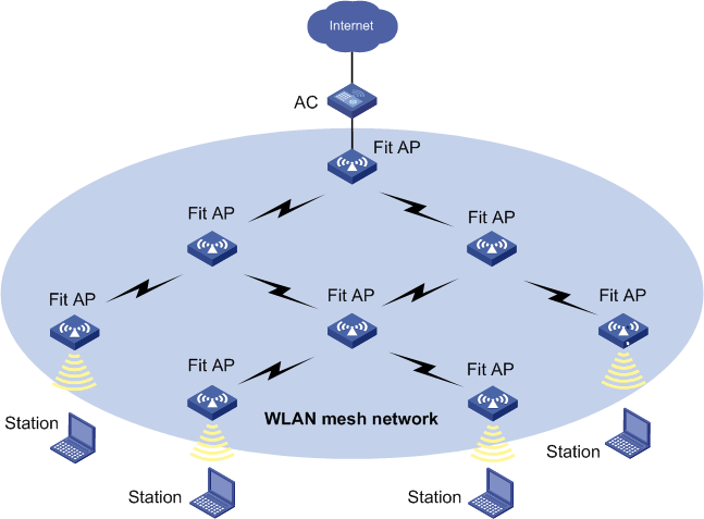
Figure 91 Typical WLAN mesh network (fat AP application)
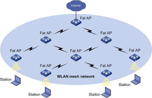
Mesh management is used for establishing and maintaining mesh networks. Mesh management includes the following objects:
· Mesh profile
· Mesh policy
· Mesh interface
· Peer AP MAC address
· Mesh topology
Only the Comware-based ACs and APs support mesh management.
Managing mesh profiles
A mesh profile is mapped to a mesh point (MP) so that it can provide mesh services to other MPs that have the same mesh profile mapped. The following information describes mesh profile management operations.
Viewing mesh profile list
1. Click the Service tab.
2. From the navigation tree, select WLAN Manager > Resource Management > ACs or WLAN Manager > Resource Management > Fat APs.
3. Click the device label of an AC or fat AP to enter the device information page.
4. On the Mesh Management menu on the lower right corner of the page, click Mesh Profile Management.
The Mesh Profile Management displays all mesh profiles.
Mesh Profile List contents
¡ Mesh Profile ID—ID of the mesh profile.
¡ Mesh ID—ID of the mesh network.
¡ Link Keep Alive Interval—Interval for sending keepalives, in seconds. If an AP has not received a response from its peer AP after three attempts of sending keepalives, the mesh link disconnects.
¡ Link Backhaul Rate—Backhaul rate of the mesh link. The value varies with radio types, and must be the same in one mesh network.
¡ Enable Mesh Profile—Indicates whether the mesh profile is enabled. A mesh profile can be enabled only when it is bound to a mesh interface with port security configured.
¡ Enable MKD Service—Indicates whether the MKD service for the mesh profile is enabled. It is supported on ACs only.
¡ Operation—Click the Operation icon ![]() to modify or delete a mesh profile and to view radios bound to the
mesh profile.
to modify or delete a mesh profile and to view radios bound to the
mesh profile.
On the Mesh Profile Management page of an AC, radios to be bound to a mesh profile are displayed.
Radio List contents
¡ Admin Status—Administrative state for the radio. Options are Up and Down.
¡ Radio ID—ID of the radio.
¡ AP Template Name—Name of the template used by the AP to which the radio belongs.
¡ Radio Type—Select a type of the radio from the list. Options are:
- 802.11a
- 802.11b
- 802.11g
- 802.11gn
- 802.11an
¡ Mesh Profile ID—ID of the mesh profile to which the radio has been bound. This field displays 0 if the radio has not been bound to any mesh profile.
¡ Delete—Click the Delete icon ![]() to delete a radio that is not required to be bound to a mesh
profile.
to delete a radio that is not required to be bound to a mesh
profile.
On the Mesh Profile Management page of a fat AP, all radios of the fat AP are displayed.
Radio Information contents
¡ Interface—Radio interface to be bound to a mesh profile. Click the interface link to enter the fat AP radio details page.
¡ Radio Type—Select a type of the radio from the list. Options are:
- 802.11a
- 802.11b
- 802.11g
- 802.11bg
- 802.11at
- 802.11an
- 802.11gn
- 802.11n (2.4GHz)
- 802.11bgn
- 802.11n
- 802.11n (5GHz).
¡ Channel—Channel for the radio, which varies with radio type.
¡ Max Transmission Power—Maximum transmission power for the radio.
¡ Modify—Click the Modify icon ![]() to modify the radio parameters of the fat AP. For more information,
see "Modifying radio
parameters for a fat AP."
to modify the radio parameters of the fat AP. For more information,
see "Modifying radio
parameters for a fat AP."
5. Click Related Operations, and then select MP Policy Management or Mesh Interface Management in the menu that appears.
Viewing mesh profile details
1. Click the Service tab.
2. From the navigation tree, select WLAN Manager > Resource Management > ACs or WLAN Manager > Resource Management > Fat APs.
3. Click the device label of an AC or fat AP to enter the device information page.
4. On the Mesh Management menu on the lower right corner of the page, click Mesh Profile Management to enter the Mesh Profile List page.
5. Click a mesh profile link.
A dialog box opens, displaying information about Mesh Profile ID, Mesh ID, Mesh Interface ID, Link Keep Alive Interval (s), Link Backhaul Rate (Mb/s), Enable Mesh Profile, and Enable MKD Service.
Parameter list contents
¡ Mesh Interface ID—ID of the interface that is bound to a mesh profile. An interface can be bound to only one mesh profile.
For information about other parameters, see "Viewing mesh profile list."
6. Click Close.
Adding a mesh profile
1. Click the Service tab.
2. From the navigation tree, select WLAN Manager > Resource Management > ACs or WLAN Manager > Resource Management > Fat APs.
3. Click the device label of an AC or fat AP to enter the device information page.
4. On the Mesh Management menu on the lower right corner of the page, click Mesh Profile Management.
The Mesh Profile Management page opens.
5. Click Add Mesh Profile.
6. Set the following parameters of the mesh profile:
¡ Mesh Profile ID—Enter an ID for the mesh profile. A mesh profile ID must be unique on the same device.
¡ Mesh ID—Enter an ID for the mesh network. The ID cannot be the same as an existing one.
¡ Binding Mesh Interface—If you select this option, you must set the Mesh Interface ID. If you do not select this option, the mesh profile cannot be enabled.
¡ Mesh Interface ID—ID of the mesh interface to be bound to the mesh profile. One mesh interface can be bound to only one mesh profile.
¡ Link Backhaul Rate—Backhaul rate of the mesh link. The value varies with radio types, and must be the same in one mesh network.
¡ Link Keep Alive Interval—Interval for sending keepalives, in seconds. If an AP has not received a response from its peer AP after three attempts of sending keepalives, the mesh link disconnects.
¡ Enable Mesh Profile—Enable the mesh profile. A mesh profile can be enabled only when it is bound to a mesh interface with port security configured.
¡ Enable MKD Service—Set the AC as the MKD device for the mesh profile. It is supported on ACs only.
7. Click OK.
Modifying a mesh profile
2. From the navigation tree, select WLAN Manager > Resource Management > ACs or WLAN Manager > Resource Management > Fat APs.
3. Click the device label of an AC or fat AP to enter the device information page.
4. On the Mesh Management menu on the lower right corner of the page, click Mesh Profile Management.
The Mesh Profile Management page opens.
5. Click the Operation
icon ![]() of the
target mesh profile, and then click the Modify icon
of the
target mesh profile, and then click the Modify icon
![]() .
.
6. Modify the parameters for the mesh profile. Mesh Profile ID cannot be modified. For more information about other parameters, see "Adding a mesh profile."
7. Click OK.
Deleting a mesh profile
If the mesh profile has been bound to a radio, it cannot be deleted. You must unbind the radio before deleting the mesh profile. For more information about unbinding radios, see "Unbinding a mesh profile."
To delete a mesh profile:
1. Click the Service tab.
2. From the navigation tree, select WLAN Manager > Resource Management > ACs or WLAN Manager > Resource Management > Fat APs.
3. Click the device label of an AC or fat AP to enter the device information page.
4. On the Mesh Management menu on the lower right corner of the page, click Mesh Profile Management.
The Mesh Profile Management page opens.
5. Click the Operation
icon ![]() of the
target mesh profile and select Delete from the
shortcut menu.
of the
target mesh profile and select Delete from the
shortcut menu.
6. Click OK.
Binding a mesh profile
This function allows you to bind a mesh profile to multiple radios so that mesh services can be provided between an AC and fit APs, and between fat APs.
Binding a mesh profile to radios on a fit AP
1. Click the Service tab.
2. From the navigation tree, select WLAN Manager > Resource Management > ACs.
3. Click the device label of an AC.
4. On the Mesh Management menu on the lower right corner of the page, click Mesh Profile Management.
The Mesh Profile Management page opens.
5. In the Radio List area, click Add.
The window for selecting radios opens.
6. Select the radios. The stronger the radio signal, the more stable the mesh link is. As a best practice, select the 802.11a radio.
Or, you can set search criteria to query radios before selecting them, as follows:
a. Enter search conditions for any of the following:
- AP Label, AP Name
- Serial Number
- Radio Type
- Admin Status
- Mesh Profile ID
- Location
An empty field or a field that is set to Unlimited does not serve as a query criterion.
b. Click Query.
The radio list displays all matching radios.
7. Click Reset to clear the query criteria and display all radios. Click OK.
The selected radios are displayed.
8. In the Mesh Profile List area, select the mesh profile to be bound.
9. Click Bind Mesh Profile.
The operation result page displays the binding result.
Binding a mesh profile to radios on a fat AP
1. Click the Service tab.
2. From the navigation tree, select WLAN Manager > Resource Management > Fat APs.
3. Click the name link of a fat AP to enter the device information page.
4. On the Mesh Management menu on the lower right corner of the page, click Mesh Profile Management.
The Mesh Profile Management page opens.
5. In the radio information area, click the Modify icon ![]() of the radio to be bound. The stronger the radio signal, the more
stable the mesh link is. As a best practice, use the 802.11a radio.
of the radio to be bound. The stronger the radio signal, the more
stable the mesh link is. As a best practice, use the 802.11a radio.
6. Select a mesh profile ID from the Mesh Profile ID list. The mesh profiles that have been added to the fat AP are available on the list.
7. Select a channel from the Channels in Use list.
Channel varies with radio type. You cannot set this option to Auto.
8. Click OK.
The operation result page displays the binding result.
Unbinding a mesh profile
After you unbind a mesh profile, you can delete the mesh profile.
Unbinding a mesh profile from radios on a fit AP
1. Click the Service tab.
2. Select WLAN Manager > Resource Management > ACs.
3. Click the name link of an AC to enter the device information page.
4. On the Mesh Management menu on the lower right corner of the page, click Mesh Profile Management.
The Mesh Profile Management page opens.
5. In the Radio List area, click Add.
The dialog box for selecting radios opens.
6. Select the radios from which you want to unbind the profile.
Or, you can set search criteria to query radios before selecting them, as follows:
a. Enter search conditions for the following:
- AP Label
- AP Name
- Serial Number
- Radio Type
- Admin Status
- Mesh Profile ID
- Location.
An empty field or a field that is set to Unlimited does not serve as a query criterion.
b. Click Query.
The radio list displays all matching radios.
Click Reset to clear the query criteria and display all radios.
7. Click OK.
The selected radios are displayed.
8. In the Mesh Profile List area, select the mesh profile.
9. Click Unbind Mesh Profile.
The operation result page displays the result.
Unbinding a mesh profile from radios on a fat AP
1. Click the Service tab.
2. From the navigation tree, select WLAN Manager > Resource Management > Fat APs.
3. Click the name link of a fat AP to enter the device information page.
4. On the Mesh Management menu on the lower right corner of the page, click Mesh Profile Management.
The Mesh Profile Management page opens.
5. Click the Modify
icon ![]() .
.
6. Select None from the Mesh Profile ID list.
7. Click OK.
Viewing radios bound to a mesh profile
1. Click the Service tab.
2. From the navigation tree, select WLAN Manager > Resource Management > ACs or WLAN Manager > Resource Management > Fat APs.
3. Click the device label of an AC or fat AP to enter the device information page.
4. On the Mesh Management menu on the lower right corner of the page, click Mesh Profile Management.
The Mesh Profile Management page opens.
5. Click the Operation
icon ![]() of a
mesh profile select the Bound Radios icon
of a
mesh profile select the Bound Radios icon ![]() from the shortcut
menu.
from the shortcut
menu.
The Radio List dialog box opens, displaying radios bound to the mesh profile. You can perform the following operations:
¡ Unbind—Select the radios that you want to unbind from the mesh profile, and then click Unbind to remove the bindings.
¡ Close—Click Close to close the dialog box.
Managing MP policies
Link formation and maintenance are driven by the attributes specified in the MP policy. You can perform the following operations by MP policy management.
Viewing an MP policy
1. Click the Service tab.
2. From the navigation tree, select WLAN Manager > Resource Management > ACs or WLAN Manager > Fat APs.
3. Click the device label of an AC or fat AP to enter the device information page.
4. On the Mesh Management menu on the lower right corner of the page, click MP Policy Management.
The MP Policy Management page opens.
MP Policy List contents
¡ Policy Name—Name of the MP policy.
¡ Enable Link Initiation—Link initiation status of the MP policy. Options are Enabled and Disabled. If the link initiation is enabled, the AP searches its peer AP.
¡ Link Maximum Number—Maximum number of mesh links that a radio of an AP can establish with other APs.
¡ Link Hold RSSI—Minimum RSSI to allow a link to be formed and held. Once the RSSI of an active link is smaller than this value, a link switch happens.
¡ Link Hold Time—Minimum time period for keeping an active link up. Within the link hold time, an active link remains up even if a link switch margin is reached. For more information about link switch margin and link switching priority, see "Adding an MP policy."
¡ Link Saturation RSSI—Maximum RSSI for an active link. If the value is reached, a link switch happens.
¡ Probe Request Interval—Interval for sending probe requests by an AP. The AP sends probe requests to scan peer APs, responds to responses, and establishes a neighbor table.
¡ Operation—Click the Operation icon ![]() of an MP policy to modify or delete the MP policy, and display the
radios bound to the MP policy. You cannot modify or delete the default MP
policy default_mp_plcy.
of an MP policy to modify or delete the MP policy, and display the
radios bound to the MP policy. You cannot modify or delete the default MP
policy default_mp_plcy.
5. Click More, and select AP Configuration, Mesh Interface Management, or Mesh Profile Management to enter the configuration page.
If the MP Policy List contains enough entries, the following navigational aids are displayed.
Navigating the MP Policy List
¡ Click
the Next Page icon ![]() to page forward in the MP Policy List.
to page forward in the MP Policy List.
¡ Click
the Last Page icon ![]() to page forward to the end of the MP Policy
List.
to page forward to the end of the MP Policy
List.
¡ Click
the Previous Page icon ![]() to page backward in the MP Policy List.
to page backward in the MP Policy List.
¡ Click
the First Page icon ![]() to page backward to the front of the MP Policy
List.
to page backward to the front of the MP Policy
List.
¡ Click 8, 15, 50, 100, or 200 at the upper right of the MP Policy List to specify the number of items you want to display on each page.
6. On the MP Policy Management page of an AC, radios to be bound to MP policies are displayed.
Radio list contents
¡ Admin Status—Administrative state for the radio. Options are Up and Down.
¡ Radio ID—ID of the radio.
¡ AP Template Name—Name of the template used by the AP to which the radio belongs.
¡ Radio Type—Select a type of the radio from the list. Options are:
- 802.11a
- 802.11b
- 802.11g
- 802.11gn
- 802.11an
¡ MP Policy Name—Name of the MP policy to which radios are bound. By default, the default MP policy default_mp_plcy is bound to all radios.
¡ Delete—Click the Delete icon ![]() to delete the radios that are not required to be bound to the MP
policy.
to delete the radios that are not required to be bound to the MP
policy.
7. On the MP Policy Management page of a fat AP, all radios of a fat AP are displayed.
Radio list contents
¡ Interface—Radio interface bound to MP policies. Click the interface link to enter the fat AP radio details page.
¡ Radio Type—Select a type of the radio from the list. Option are:
- 802.11a
- 802.11b
- 802.11g
- 802.11bg
- 802.11at
- 802.11an
- 802.11gn
- 802.11n (2.4GHz)
- 802.11bgn
- 802.11n
- 802.11n (5GHz)
¡ Channel—Channel for a radio, which varies with radio type.
¡ Max Transmission Power—Maximum transmission power for the radio.
¡ Modify—Click the Modify icon ![]() to modify the parameters of fat AP radios. For more information
about modifying radio parameters, see "Modifying radio parameters for a fat AP."
to modify the parameters of fat AP radios. For more information
about modifying radio parameters, see "Modifying radio parameters for a fat AP."
8. Click Related Operations, and then select Mesh Profile Management or Mesh Interface Management in the menu that appears.
Viewing MP policy details
2. From the navigation tree, select WLAN Manager > Resource Management > ACs or WLAN Manager > Resource Management > Fat APs.
3. Click the device label of an AC or fat AP to enter the device information page.
4. On the Mesh Management menu on the lower right corner of the page, click MP Policy Management.
The MP Policy Management page opens.
5. Click the link of the target MP policy name.
A dialog box opens, displaying detailed information about the MP policy.
MP policy details
¡ Policy Name—Name of the MP policy.
¡ Enable Link Initiation—Link initiation status of the MP policy Options are Enabled and Disabled. If the link initiation is enabled, the AP searches its peer AP.
¡ Link Maximum Number—Maximum number of mesh links that a radio of an AP can establish with other APs.
¡ Link Rate Mode—Method to calculate the cost of a mesh link. Options are:
- Fixed—Uses the maximum fixed rate of the current radio to calculate the cost of a mesh link.
- Realtime—Uses realtime RSSI to calculate the cost of a mesh link.
¡ Probe Request Interval—Interval for sending probe requests by an AP. The AP sends probe requests to scan peer APs, responds to responses, and establishes a neighbor table.
¡ Link Hold RSSI—Minimum RSSI to allow a link to be formed and held. Once the RSSI of an active link is smaller than this value, a link switch happens.
¡ Link Hold Time—Minimum time period for keeping an active link up. Within the link hold time, an active link remains up even if link switch margin is reached.
¡ Link Saturation RSSI—Maximum RSSI for an active link. If the value is reached, a link switch happens.
¡ Link Switch Margin—If the RSSI of the new link is greater than that of the current active link by the link switch margin, active link switch happens. This function is supported only on mesh networks of AC application.
¡ Enable Role Authenticator—Indicates whether role authenticator is enabled. Role authenticator must be enabled on one of two APs to establish a mesh link. This function is supported only on mesh networks of AC application.
¡ Enable MLSP—Indicates whether the MLSP protocol is enabled. MLSP is used to create and break links during train movement to ensure an active link is available on a train MP at any given time. This function is supported only on mesh networks of an AC application.
¡ MLSP Proxy MAC Address—MAC address of the device connecting to the MLSP-enabled fit AP. When a link switchover occurs in a subway mesh network, the train MP, if configured with MLSP proxy, sends a gratuitous ARP packet so the switch that connects to the rail MP can quickly update the ARP entry to avoid traffic interruption. This function is supported only on mesh networks of AC application. This item is displayed for mesh networks of an AC application when MLSP is enabled and proxy MAC address is configured.
6. Click Close.
Adding an MP policy
1. Click the Service tab.
2. From the navigation tree, select WLAN Manager > Resource Management > ACs or WLAN Manager > Resource Management > Fat APs.
3. Click the device label of an AC or fat AP to enter the device information page.
4. On the Mesh Management menu on the lower right corner of the page, click MP Policy Management.
The MP Policy Management page opens.
5. Click Add Policy to enter the Add MP Policy page.
6. Set the following parameters:
¡ Policy Name—Enter a name for the MP policy. An MP policy name must be unique on the same device.
¡ Enable Link Initiation—Select the option to enable the link initiation. If the link initiation is enabled, the AP searches its peer AP.
¡ Link Maximum Number—Set the maximum number of mesh links that a radio of an AP can establish with other APs.
¡ Link Rate Mode—Select a method to calculate the cost of a mesh link. Options are:
- Fixed—Uses maximum fixed rate of the current radio to calculate the cost of a mesh link.
- Realtime—Uses realtime RSSI to calculate the cost of a mesh link.
¡ Probe Request Interval—Set the interval for sending probe requests by an AP. The AP sends probe requests to scan peer APs, responds to responses, and establishes a neighbor table.
¡ Link Hold RSSI—Set the minimum RSSI to allow a link to be formed and held. Once the RSSI of an active link is smaller than this value, a link switch happens.
¡ Link Hold Time—Set the minimum time period for keeping an active link up. Within the link hold time, an active link remains up even if link switch margin is reached.
¡ Link Saturation RSSI—Set the maximum RSSI for an active link. If the value is reached, a link switch happens.
¡ Link Switch Margin—Set the link switch margin. If the RSSI of the new link is greater than that of the current active link by the link switch margin, an active link switch happens. This function is supported only on mesh networks of AC application.
|
|
NOTE: The priorities of parameters that determine the link switch in ascending order are as follows: link switch margin, link hold time, and link saturation RSSI/link hold RSSI. · When the link hold time expires, if the RSSI of the new link is greater than that of the current active link by the link switch margin, an active link switch happens. · Within the link hold time, an active link switch does not happen except when the active link RSSI exceeds the link saturation RSSI, or is below the link hold RSSI. |
¡ Enable Role Authenticator—Select the option to enable role authenticator. Role authenticator must be enabled on one of two APs to establish a mesh link. This function is supported only on mesh networks of an AC application.
¡ Enable MLSP—Select the option to enable the MLSP protocol. The link initiation must be enabled before you enable MLSP. MLSP is used to create and break links during train movement to ensure an active link is available on a train MP at any given time. When MLSP is disabled on a radio, the MLSP proxy MAC addresses configured under the current MP policy are removed. This function is supported only on mesh networks of an AC application.
¡ MLSP Proxy MAC Address—Set the MAC address of the device connecting to the MLSP-enabled fit AP.
Enter a MAC address in the MLSP Proxy MAC Address field, and then click Add to add the address to the MLSP proxy MAC address list. You can repeat this step to add more MAC addresses.
To delete a MAC addresses from the address list, select the target MAC address, and then click Delete.
When a link switchover occurs in a subway mesh network, the train MP, if configured with MLSP proxy, sends a gratuitous ARP packet so the switch that connects to the rail MP can quickly update the ARP entry to avoid traffic interruption. This function is supported only on mesh networks of an AC application.
7. Click OK.
Modifying an MP policy
You cannot modify the default MP policy default_mp_plcy that has been bound to radios. To modify a non-default MP policy, unbind it from the radios first. For more information about unbinding an MP policy with radios, see "Viewing radios bound to an MP policy and removing the bindings."
To modify an MP policy:
1. Click the Service tab.
2. From the navigation tree, select WLAN Manager > Resource Management > ACs or WLAN Manager > Resource Management > Fat APs.
3. Click the device label of an AC or fat AP to enter the device information page.
4. On the Mesh Management menu on the lower right corner of the page, click MP Policy Management.
The MP Policy Management page opens.
5. Click the Operation
icon ![]() of an MP
policy and select the Modify icon
of an MP
policy and select the Modify icon ![]() from the shortcut
menu.
from the shortcut
menu.
6. Modify MP policy parameters as required. You cannot modify the policy name. For more information about other parameters, see "Adding an MP policy."
7. Click OK.
Deleting an MP policy
You cannot delete the default MP policy default_mp_plcy that has been bound to radios. To delete a non-default MP policy, unbind it from the radios first. For more information about unbinding an MP policy with radios, see "Viewing radios bound to an MP policy and removing the bindings."
To delete an MP policy:
1. Click the Service tab.
2. From the navigation tree, select WLAN Manager > Resource Management > ACs or WLAN Manager > Resource Management > Fat APs.
3. Click the device label of an AC or fat AP to enter the device information page.
4. On the Mesh Management menu on the lower right corner of the page, click MP Policy Management.
The MP Policy Management page opens.
5. Click the Operation
icon ![]() of an MP
policy, and then click the Delete icon
of an MP
policy, and then click the Delete icon ![]() on the menu that
appears.
on the menu that
appears.
6. Click OK.
Binding an MP policy
You can bind an MP policy to multiple radios. The settings in the MP policy trigger the establishment and maintenance of the mesh links on the radios. By default, the default MP policy default_mp_plcy is bound to radios.
Binding an MP policy to the radios on a fit AP
1. Click the Service tab.
2. From the navigation tree, select WLAN Manager > Resource Management > ACs.
3. Click the device label of an AC to enter the device information page.
4. On the Mesh Management menu on the lower right corner of the page, click MP Policy Management.
The MP Policy Management page opens.
5. Click Add in the Radio List area.
The dialog box for selecting radios opens.
6. Select the radios from which you want to bind the MP policy. The stronger the radio signal, the more stable the mesh link is. As a best practice, select the 802.11a radio.
Or, you can set search criteria to query radios before selecting them, as follows:
a. Enter selection conditions for the following:
- AP Label
- AP Name
- Serial Number
- Radio Type
- Admin Status
- MP Policy Name
- Location.
An empty field or a field that is set to Unlimited does not serve as a query criterion.
b. Click Query.
The radio list displays all matching radios.
Click Reset to clear the query criteria and display all radios.
7. Click OK.
The selected radios are displayed.
8. In the MP Policy List area, select the MP policy to be bound to the radios.
9. Click Bind.
The operation result page displays the binding result.
Binding an MP policy to the radios on a fat AP:
1. Click the Service tab.
2. From the navigation tree, select WLAN Manager > Resource Management > Fat APs.
3. Click the label link of a fat AP to enter the device information page.
4. On the Mesh Management menu on the lower right corner of the page, click MP Policy Management.
The MP Policy Management page opens.
5. In the Radio
Information area, click the Modify icon ![]() of the radio to
be bound. The stronger the radio signal, the more stable the mesh link is. As a
best practice, use the 802.11a radio.
of the radio to
be bound. The stronger the radio signal, the more stable the mesh link is. As a
best practice, use the 802.11a radio.
6. Select the channel from the Channels in Use list. The channel number varies with radio type. You cannot set this option to Auto.
7. Select the MP policy to be bound to the radio from the MP Policy list. The MP policies that have been added to the fat AP are available on the list.
8. Click OK.
Viewing radios bound to an MP policy and removing the bindings
WSM allows you to view radios bound to an MP policy and remove the bindings. You can also modify and delete an MP policy without any binding. After you unbind an MP policy from a radio, the default MP policy default_mp_plcy is bound to the radio.
To view the radios bound to an MP policy:
1. Click the Service tab.
2. From the navigation tree, select WLAN Manager > Resource Management > ACs or WLAN Manager > Resource Management > Fat APs.
3. Click the device label of an AC or fat AP to enter the device information page.
4. On the Mesh Management menu on the lower right corner of the page, click MP Policy Management.
The MP Policy Management page opens.
5. Click the Operation
icon ![]() of an MP
policy and select the Bound Radios icon
of an MP
policy and select the Bound Radios icon![]() from
the shortcut menu.
from
the shortcut menu.
The Radio List dialog box opens, displaying radios bound to the MP policy. You can perform the following operations:
¡ Unbind—Select the radios that you want to unbind the MP policy from, and then click Unbind to remove the bindings.
¡ Close—Click Close to close the dialog box.
Managing mesh interfaces
You can perform the following operations by mesh interface management.
Viewing mesh interface list
1. Click the Service tab.
2. From the navigation tree, select WLAN Manager > Resource Management > ACs or WLAN Manager > Resource Management > Fat APs.
3. Click the device label of an AC or fat AP to enter the device information page.
4. On the Mesh Management menu on the lower right corner of the page, click Mesh Interface Management.
The Mesh Interface Management page opens.
Mesh Interface List contents
¡ Description—Interface description that comprises WLAN-MESH and interface ID.
¡ Mesh Profile ID—ID of the mesh profile that is bound to an interface.
¡ Port Security Mode—Port security mode of an interface. PSK is supported only. If port security is not configured, noRestrictions is displayed. The mesh interface in this mode is invalid.
¡ VLAN—ID of the VLAN to which the interface belongs.
¡ Operation—Click the Operation icon ![]() for a mesh interface to bring up the operation menu.
for a mesh interface to bring up the operation menu.
You can delete mesh interfaces, modify port security, modify VLAN, and modify mesh profiles. For more information about these operations, see "Configuring port security for mesh interfaces," "Modifying the VLAN to which mesh interfaces belong," "Deleting mesh interfaces," and "Modifying a mesh profile."
5. Click More, and select MP Policy Management or Mesh Profile Management to enter the configuration page.
If the Mesh Interface List contains enough entries, the following navigational aids will be displayed:
¡ Click
the Next Page icon ![]() to page forward in the Mesh Interface List.
to page forward in the Mesh Interface List.
¡ Click
the Last Page icon ![]() to page forward to the end of the Mesh Interface
List.
to page forward to the end of the Mesh Interface
List.
¡ Click
the Previous Page icon ![]() to page backward in the Mesh Interface List.
to page backward in the Mesh Interface List.
¡ Click
the First Page icon ![]() to page backward to the front of the Mesh Interface
List.
to page backward to the front of the Mesh Interface
List.
Click 8, 15, 50, 100, or 200 on the upper right of the Mesh Interface List to configure how many items per page you want to display.
|
|
NOTE: You can sort the Mesh Interface List by every field except the Operation field. Click the column label to sort the list by the selected field. The column label allows you to toggle between various sort options specific to each field. |
6. Click Related Operations, and then select Mesh Profile Management or MP Policy Management from the shortcut menu to enter the corresponding page.
Querying mesh interfaces
2. From the navigation tree, select WLAN Manager > Resource Management > ACs or WLAN Manager > Resource Management > Fat APs.
3. Click the device label of an AC or fat AP to enter the device information page.
4. On the Mesh Management menu on the lower right corner of the page, click Mesh Interface Management.
The Mesh Interface Management page opens.
5. Enter one or more of the following query criteria in the Query area:
¡ Description—Description for the mesh interface. WSM supports fuzzy matching for this field.
¡ Mesh Profile ID—ID of the mesh profile that is bound to the mesh interface. WSM supports fuzzy matching for this field.
An empty field or a field that is set to Unlimited does not serve as a query criterion.
6. Click the Query icon
![]() . The Mesh Interface Management page displays all mesh
interfaces matching the query criteria.
. The Mesh Interface Management page displays all mesh
interfaces matching the query criteria.
7. Clear the Query
field, and click the Query icon ![]() to display all mesh
interfaces.
to display all mesh
interfaces.
Adding a mesh interface
2. From the navigation tree, select WLAN Manager > Resource Management > ACs or WLAN Manager > Resource Management > Fat APs.
3. Click the device label of an AC or fat AP to enter the device information page.
4. On the Mesh Management menu on the lower right corner of the page, click Mesh Interface Management.
The Mesh Interface Management page opens.
5. Click Add Interface to enter the Add Interface page.
6. Enter an interface ID.
A description is generated based on the interface ID. For example, if you enter 10 as the interface ID, the description for the interface is WLAN-MESH10.
7. Click OK.
The operation result is displayed. If the operation fails, the failure reason is displayed.
8. Click Back to return to the Mesh Interface Management page.
Configuring port security for mesh interfaces
After you add a mesh interface, you must configure port security for the interface. If you do not configure port security for the interface, noRestrictions is displayed for the port security mode of the interface in the mesh interface list.
To configure port security for a mesh interface:
1. Click the Service tab.
2. From the navigation tree, select WLAN Manager > Resource Management > ACs or WLAN Manager > Resource Management > Fat APs.
3. Click the device label of an AC or fat AP to enter the device information page.
4. On the Mesh Management menu on the lower right corner of the page, click Mesh Interface Management.
The Mesh Interface Management page opens.
5. Use one of the following methods to enter the Modifying Port Security page:
Method 1—Modify port security for one interface:
a. Click the Operation
icon ![]() of a
mesh interface.
of a
mesh interface.
b. From the menu, select the Modify Port Security icon ![]() .
.
Method 2—Modify port security for multiple interfaces:
a. Select the mesh interfaces for which you want to modify the port security mode.
b. Click Modifying Port Security.
6. Set the following parameters:
¡ Description—Description for the mesh interface, comprising WLAN-MESH and interface ID. This field cannot be modified, and does not appear when you modify the port security mode for multiple interfaces.
¡ Port Security Mode—This field is set to PSK and cannot be modified. Only PSK is supported. PSK is the negotiation key between two APs. You must configure the same PSK on the local and peer APs.
¡ Key Type—Select a type from the list. Options are 11Key and a blank.
¡ PSK Mode—Select a PSK mode. Options are pass-phrase, raw-key, and a blank.
¡ PSK—Enter a PSK string. If PSK Mode is set to a blank option, do not enter any value.
7. Click OK.
The operation result is displayed. If the operation fails, reasons for the failure are displayed.
8. Click Back to return to the Mesh Interface Management page.
Modifying the VLAN to which mesh interfaces belong
You can modify the VLAN to which one or more mesh interfaces belong. If the interface has been bound to a mesh profile, you cannot modify the VLAN to which the interface belongs. Unbind the interface from the mesh profile before modifying the VLAN. For more information about unbinding an interface from a mesh profile, see "Modifying a mesh profile."
To modify the VLAN to which a mesh interface belongs:
1. Click the Service tab.
2. From the navigation tree, select WLAN Manager > Resource Management > ACs or WLAN Manager > Resource Management > Fat APs.
3. Click the device label of an AC or fat AP to enter the device information page.
4. On the Mesh Management menu on the lower right corner of the page, click Mesh Interface Management.
The Mesh Interface Management page opens.
5. Use one of the following methods to enter the Modify VLAN page:
Method 1—Modify the VLAN for one interface:
a. Click the Operation
icon ![]() of a
mesh interface.
of a
mesh interface.
b. From the menu, select the Modify VLAN icon ![]() .
.
Method 2—Modify the VLAN for multiple interfaces.
a. Select the mesh interfaces for which you want to modify the VLAN.
b. Click Modify VLAN.
6. Select a VLAN ID from the VLAN list. VLANs created on the device are available on the list.
7. Click OK.
The operation result is displayed. If the operation fails, reasons for the failure are displayed.
8. Click Back to return to the Mesh Interface Management page.
Deleting mesh interfaces
You can delete one or more mesh interfaces. If the interface has been bound to a mesh profile, you cannot delete the interface. Unbind the interface from the mesh profile before deleting the interface. For more information about unbinding an interface from a mesh profile, see "Modifying a mesh profile."
To delete a mesh interface:
1. Click the Service tab.
2. From the navigation tree, select WLAN Manager > Resource Management > ACs or WLAN Manager > Resource Management > Fat APs.
3. Click the device label of an AC or fat AP to enter the device information page.
4. On the Mesh Management menu on the lower right corner of the page, click Mesh Interface Management.
The Mesh Interface Management page opens.
5. Use one of the following methods to delete one or more mesh interfaces:
Method 1—Delete one mesh interface:
a. Click the Operation
icon ![]() of a mesh interface.
of a mesh interface.
b. From the menu, select the Delete Interface icon ![]() , and then confirm your operation.
, and then confirm your operation.
Method 2—Delete multiple mesh interfaces.
a. Select the mesh interfaces to be deleted.
b. Click Delete Mesh Interface, and then confirm your operation.
Specifying MAC addresses of peers
You can specify a MAC address of a peer for an AP so that the AP can establish a mesh network only with its peer. If you do not specify the peer MAC address for an AP, the AP establishes a mesh network with all APs.
When deploying a mesh network between APs, you can configure a peer MAC address for each radio of an AP.
To specify the MAC address of a peer:
1. Click the Service tab.
2. From the navigation tree, select WLAN Manager > Resource Management > Fat APs or WLAN Manager > Resource Management > Fit APs.
3. Click the device label of an AP to enter the device information page.
4. In the Radio
Information area (or the Radio Interface area
on a fit AP information page), click the Configure Mesh
Peer MAC Address icon ![]() .
.
The Configure Mesh Peer MAC Address page opens.
5. Perform the following operations.
To add the MAC address of a peer:
a. Enter a MAC address in the Peer MAC Address field in the hh: hh: hh: hh: hh: hh format.
b. Click Add.
To delete the MAC address of a peer:
a. Select one or more MAC addresses to be deleted from the Peer MAC Address List.
b. Click Delete.
6. Click Back to return to the device details page.
|
|
NOTE: You can configure up to 8 peer MAC addresses for a radio. |
Mesh topology
You can view an AC mesh topology through wireless device topology, and view a fat AP mesh topology through location view topology.
Viewing an AC mesh topology
1. Click the Service tab.
2. From the navigation tree, select WLAN Manager > Wireless Topology.
A wireless topology window opens, displaying all ACs and fat APs. You can click the icon of an AC or AP to display the device basic information.
3. Right-click the icon of an AC and select Open Mesh Topology from the shortcut menu.
The mesh topology of the AC appears.
4. Click the icon of the AC to display its basic information.
5. You can perform the following operations on a fit AP that connects to the AC:
¡ Click the icon of the fit AP to display its basic information.
For more information, see "Viewing the device topology of an AC."
¡ Right-click the icon of the fit AP, and then select an operation from the shortcut menu.
Device Information displays the device details, and Display Physical Topology displays the physical connection between the AC and the fit AP.
6. Right-click the link (solid green line) between an AC and a fit AP, and then select Link Information from the shortcut menu. A solid line represents the physical connection between an AC and a fit AP. A dotted line represents a wireless connection between fit APs.
Link information for physical connections between an AC and a fit AP:
¡ Control Channel Security Policy—Security policy of the control channel used by the CAPWAP channel between an AC and a fit AP.
¡ Control Channel Startup Time—Startup time of the control channel used by the CAPWAP channel between an AC and a fit AP.
¡ Data Channel Security Policy—Security policy of the data channel used by the CAPWAP channel between an AC and a fit AP.
¡ Data Channel Startup Time—Startup time of the data channel used by the CAPWAP channel between an AC and a fit AP.
7. Right-click the link (dotted green line) between fit APs, and then select Link Information from the shortcut menu.
The Mesh Link Information dialog box opens.
Basic Information tab
¡ Left Node—Name of the left node the mesh link.
¡ Left Radio ID—Radio ID of the left node in the mesh link.
¡ Right Node—Name of the right node in the mesh link.
¡ Right Radio ID—Radio ID of the right node in the mesh link.
¡ Mesh ID—ID of the mesh network.
¡ Duration—Active time of the mesh link.
Left Node tab
¡ Device Label—Label of the left node device in the mesh link.
¡ BSS ID—MAC address of the left node device in the mesh link.
¡ Channel—Channel used by the left node device in the mesh link.
¡ RSSI—RSSI of the left node device in the mesh link.
¡ SNR—SNR of the left node device in the mesh link.
Right Node tab
¡ Device Label—Label of the right node device in the mesh link.
¡ BSS ID—MAC address of the right node device in the mesh link.
¡ Channel—Channel used by the right node device in the mesh link.
¡ RSSI—RSSI of the right node device in the mesh link.
¡ SNR—SNR of the right node device in a mesh link.
Viewing a fat AP mesh topology
1. Click the Service tab.
2. Enter the location view topology.
Method 1:
a. From the navigation tree, select WLAN Manager > Wireless Topology.
b. From the navigation tree, select Topology > Wireless Topology > Location View.
The location view topology appears.
c. Double-click a location view icon on the navigation tree, or select Open Topology from the right-click menu of a location view icon on the topology.
The topology map appears, displaying all sublocation views, fit APs, and fat APs that are redirected under this level of location view.
Method 2:
a. From the navigation tree, select WLAN Manager > View Management > Location View.
The Location List displays all location views.
b. Click the View Topology
icon ![]() of a location view.
of a location view.
The topology map appears, displaying all sublocation views, fit APs, and fat APs that are redirected under this level of location view.
3. Right-click a blank area, and then select Show Mesh Link from the shortcut menu.
The topology map displays mesh links between fat APs.
|
|
NOTE: If the location view includes fit APs that connect with each other by mesh link, the location view topology displays the mesh link between fit APs. |
4. Right-click the link (dotted green line) between fat APs, and then select Link Information from the shortcut menu.
The Mesh Link Information dialog box opens.
Basic Information tab
¡ Left Node—Name of the left node in the mesh link.
¡ Left Radio ID—Radio ID of the left node in the mesh link.
¡ Right Node—Name of the right node in the mesh link.
¡ Right Radio ID—Radio ID of the right node in the mesh link.
¡ Mesh ID—ID of the mesh network.
¡ Duration—Active time of the mesh link.
Left Node tab
¡ Device Label—Label of the left node device in the mesh link.
¡ BSS ID—MAC address of the left node device in the mesh link.
¡ Channel—Channel used by the left node device in the mesh link.
¡ RSSI—RSSI of the left node device in the mesh link.
¡ SNR—SNR of the left node device in the mesh link.
Right Node tab
¡ Device Label—Label of the right node device in the mesh link.
¡ BSS ID—MAC address of the right node device in the mesh link.
¡ Channel—Channel used by the right node device in the mesh link.
¡ RSSI—RSSI of the right node device in the mesh link.
¡ SNR—SNR of the right node device in the mesh link.
Evaluating wireless network quality
The network evaluation module is not available in WSM basic version, and is only supported by Comware-based ACs and APs.
The network evaluation module enables you to evaluate the quality and operating status of AC + fit AP WLANs and locate problems based on evaluation statistics and results.
Network evaluation includes the following parts:
· Evaluation task—You need to create an evaluation task first and set the evaluation object, evaluation date, and data collection time. After you create an evaluation task, WSM periodically collects data from the AC within the data collection time.
· Evaluation report—After data collection is completed, WSM summarizes the collected data, evaluates the APs and clients based on the predefined thresholds, and generates evaluation reports.
Configuring an evaluation task
|
|
CAUTION: When creating and executing an evaluation task, changing the location views associated with the evaluation task can affect evaluation data correctness and the evaluation task might fail. |
Based on evaluation objects, evaluation tasks can be divided into the following types:
· Location view-based evaluation task—Evaluates the WLAN in an area, such as a floor in a building.
· AC-based evaluation task—Evaluates a WLAN where fit APs are managed by the same AC.
Viewing the evaluation task list
1. Click the Service tab.
2. From the navigation tree, select WLAN Manager > Network Evaluation. The Task List page displays all evaluation tasks.
Task List contents
¡ Task Name—Name of the evaluation task.
¡ Task Type—Evaluation task type, Location View or AC .
¡ Task Status—State of the evaluation task. Options are:
- Waiting—An evaluation task is in Waiting state from the time when the task is created to an hour before the first data collection starts.
- Collecting—An evaluation task is in Collecting state one hour before the configured data collection start time is reached until 15 minutes after the configured data collection end time is reached.
The 1 hour is reserved for data collection preparation and the 15 minutes is reserved to ensure data integrity.
- Waiting for collection—An evaluation task is in Waiting for collection state from the time when the Collecting state ends to the time when the next Collecting state begins. If the start date and end date of the evaluation task are the current day, this state is not available, and the evaluation task enters Evaluating state immediately after the Collecting state is ended
- Evaluating—An evaluation task enters Evaluating state when the last data collection ends. For example, if an evaluation task lasts for three days, the task enters Evaluating state after data collection in the third day ends.
- Completed—An evaluation task enters Completed state when WSM completes data analysis and generates an evaluation report.
- Suspended—An evaluation task enters Suspended state when you manually suspend the evaluation task.
- Expired—An evaluation task enters Expired state when the evaluation task is resumed but the current time is later than the configured end time of the task.
¡ Start Date—Date when the task is started.
¡ End Date—Date when the task is completed.
¡ Data Collection Time Range—Time range where data is collected.
¡ Created by—Operator that creates the task.
¡ Created at—Time when the task is created.
¡ Operation—Click the Operation icon ![]() for an evaluation task in Waiting state
or changing from Waiting state to Suspending state to modify the evaluation task. Click the
View Evaluation Report icon
for an evaluation task in Waiting state
or changing from Waiting state to Suspending state to modify the evaluation task. Click the
View Evaluation Report icon ![]() of an evaluation task in Collecting, Waiting
for collection, Completed, Suspended, or Expired state to view the evaluation report. Table 44 shows
the task state and available operations.
of an evaluation task in Collecting, Waiting
for collection, Completed, Suspended, or Expired state to view the evaluation report. Table 44 shows
the task state and available operations.
Table 44 Task state and available operations
|
Task state |
Modify |
Delete |
Suspend |
View evaluation report |
Set task thresholds |
Re-evaluate |
|
|
Waiting |
Yes |
Yes |
Yes |
No |
Yes |
No |
|
|
Collecting |
No |
No |
No |
Yes |
Yes |
No |
|
|
Waiting for collection |
No |
Yes |
Yes |
Yes |
Yes |
No |
|
|
Evaluating |
No |
No |
No |
No |
No |
No |
|
|
Completed |
No |
Yes |
No |
Yes |
Yes |
Yes |
|
|
Suspended |
From Waiting to Suspended |
Yes |
Yes |
N/A |
No |
Yes |
No |
|
From Waiting for collection to Suspended |
No |
Yes |
N/A |
Yes |
Yes |
No |
|
|
Expired |
No |
Yes |
No |
Yes |
Yes |
Yes |
|
¡ Threshold Settings—Click the Threshold Settings icon ![]() to set thresholds for an evaluation task not in Evaluating state. For more information, see "Setting thresholds for an evaluation task."
to set thresholds for an evaluation task not in Evaluating state. For more information, see "Setting thresholds for an evaluation task."
If the Task List contains enough entries, the following navigational aids will be displayed:
· Click the Next Page
icon ![]() to page
forward in the Task List.
to page
forward in the Task List.
· Click the Last Page
icon ![]() to page
forward to the end of the Task List.
to page
forward to the end of the Task List.
· Click the Previous Page
icon ![]() to page
backward in the Task List.
to page
backward in the Task List.
· Click the First Page
icon ![]() to page
backward to the front of the Task List.
to page
backward to the front of the Task List.
Click 8, 15, 50, 100, or 200 on the upper right of the Task List to configure how many items per page you want to display.
|
|
NOTE: You can sort the Task List by every field except the Operation and Threshold Settings fields. Click the column label to sort the list by the selected field. The column label allows you to toggle between the various sort options specific to each field. |
Querying evaluation tasks
WSM provides basic query and advanced query. Basic query criteria include several key parameters for quick searches. Advanced query offers various query criteria for precise matching.
To query evaluation tasks:
1. Click the Service tab.
2. From the navigation tree, select WLAN Manager > Network Evaluation.
The Task List page displays all evaluation tasks.
3. Perform a basic query:
a. Enter the task name. WSM supports fuzzy matching for this field.
b. Click the Query icon
![]() . The Task List displays all tasks matching the query criteria.
. The Task List displays all tasks matching the query criteria.
c. Clear the Query
field, and click the Query icon ![]() to display all tasks.
to display all tasks.
4. Perform an advanced query:
a. Click the Expand
icon ![]() next to the Query field to expand the Query area. Click it again to hide the Query area.
next to the Query field to expand the Query area. Click it again to hide the Query area.
b. Enter or select one or more of the following query criteria:
¡ Task Name—Enter the name of the evaluation task. WSM supports fuzzy matching for this field.
¡ Task Status—Select the state of the evaluation task. Options are:
- Waiting
- Collecting
- Waiting for collection
- Evaluating
- Suspended
- Completed
- Expired
¡ Task type—Select the type of the evaluation task. Options are:
- Unlimited
- Location View
- AC
An empty field or a field that is set to Unlimited does not serve as a query criterion.
c. Click Query. The Task List displays all evaluation tasks matching the query criteria.
d. Click Reset to clear the query criteria and display all evaluation tasks.
Viewing detailed information about an evaluation task
1. Click the Service tab.
2. From the navigation tree, select WLAN Manager > Network Evaluation. The Task List page displays all evaluation tasks.
3. Click the name link of the evaluation task to view detailed information.
Network Evaluation Task details
¡ Task Name—Name of the evaluation task.
¡ Evaluation Object—Name of the location view to be evaluated.
¡ Task Type—Type of the evaluation task.
¡ Created by—Operator that creates the task.
¡ Created at—Time when the task is created.
¡ Start Time—Time when the task is started.
¡ End Time—Time when the task is completed.
¡ Data Collection Time Range—Time range during which data is collected.
¡ Task Description—Description for the evaluation task.
4. Click Close.
Adding an evaluation task
1. Click the Service tab.
2. From the navigation tree, select WLAN Manager > Network Evaluation. The Task List page displays all evaluation tasks.
3. Click Add. The Add Evaluation Task page opens.
4. Set the following parameters:
Basic Evaluation Task Information
¡ Task Name—Enter the name of the evaluation task.
¡ Task Type—Select the type of the evaluation task, Location View or AC. The evaluation task type determines the setting of parameter Evaluation Object.
¡ Evaluation Object—If the task type is Location View, enter the first several letters of the location view name or a space, and select the location view from the list that appears. If the task type is AC, select an AC from the list.
¡ Task Description—Enter a description for the evaluation task.
¡ Start Date—Enter the start date of
the evaluation task in YYYY-MM-DD format, or click the Calendar
icon ![]() to select one. The start date cannot be earlier than the current
date.
to select one. The start date cannot be earlier than the current
date.
¡ End Date—Enter the end date of the
evaluation task in YYYY-MM-DD format, or click the Calendar
icon ![]() to select one. The end date cannot be earlier than the start date.
to select one. The end date cannot be earlier than the start date.
Daily Data Collection Time Range
To add or modify an evaluation task, do not set overlapping data collection time ranges if the evaluation object you select overlaps with the current evaluation object.
For example, an evaluation task for location view A already exists. When you create an evaluation task for AC B and an AP managed by AC B has been added to location view A, data collection time ranges for the two tasks cannot overlap. If the time ranges overlap, the evaluation task for AC B cannot be created.
|
|
NOTE: As a best practice, set the data collection time to the time when services are busiest, because at that time the quality of WLAN can directly affect the stability of wireless services. |
Following are the data collection time ranges:
¡ Start Time—Select the start time for data collection every day. If data collection starts today, the start time must be 1 hour later than the current time.
¡ End Time—Select the end time for data collection every day. The end time must be later than the start time.
5. Click OK.
Modifying an evaluation task
You can modify an evaluation task in Waiting state or an evaluation task that has changed from Waiting state to Suspended state.
To modify an evaluation task:
1. Click the Service tab.
2. From the navigation tree, select WLAN Manager > Network Evaluation. The Task List page displays all evaluation tasks.
3. Click the Operation
icon ![]() for the
target evaluation task.
for the
target evaluation task.
4. Modify the basic information and data collection time range as needed. For more information, see "Adding an evaluation task."
The task name cannot be modified.
5. Click OK.
Deleting an evaluation task
Deleting an evaluation task deletes all data related to the task. An evaluation task in Collecting or Evaluating state cannot be deleted.
To delete an evaluation task:
1. Click the Service tab.
2. From the navigation tree, select WLAN Manager > Network Evaluation.
The Task List page displays all evaluation tasks.
3. Select the target evaluation task.
4. Click Delete.
5. In the confirmation dialog box, click OK.
Suspending an evaluation task
Only an evaluation task in Waiting or Waiting for collection state can be suspended.
To suspend an evaluation task:
1. Click the Service tab.
2. From the navigation tree, select WLAN Manager > Network Evaluation.
The Task List page displays all evaluation tasks.
3. Select the target evaluation task.
4. Click Suspend.
5. In the confirmation dialog box, click OK.
Resuming an evaluation task
After you resume an evaluation task, if the current time is earlier than the end time of the task, the evaluation task continues. If the current time is later than the end time of the task, the evaluation task is in expired state and is terminated.
To resume an evaluation task:
1. Click the Service tab.
2. From the navigation tree, select WLAN Manager > Network Evaluation.
The Task List page displays all evaluation tasks.
3. Select the target evaluation task.
4. Click Resume.
Setting global thresholds
You can set global thresholds for evaluation indexes. WSM uses the evaluation indexes to evaluate APs and clients and display some of the pie charts for overall evaluation information.
To set global thresholds:
1. Click the Service tab.
2. From the navigation tree, select WLAN Manager > Network Evaluation.
The Task List page displays all evaluation tasks.
3. Click Set Global Threshold. The Global Threshold Settings page opens.
4. Set thresholds for high-rate packets. Packets whose rates are higher than the configured thresholds are high-rate packets. WSM uses the number of high-rate packets to calculate the high-rate packet ratio.
a. Click the Setting link for High-Rate Packet Settings.
b. Select a threshold for each of the following indexes:
- 802.11a Packet Rate (Mbps)
- 802.11an Packet Rate (Mbps)
- 802.11b Packet Rate (Mbps)
- 802.11g Packet Rate (Mbps)
- 802.11gn Packet Rate (Mbps)
If the rate of packets sent by the corresponding type of radio reaches the threshold, the packets are considered as high-rate packets.
c. Click OK.
5. Set thresholds for AP evaluation indexes. WSM uses the thresholds to evaluate APs' operating status in an evaluation task. You can view the evaluation results in overall AP evaluation information in the evaluation report.
a. Click the Setting link for AP Evaluation Index Settings.
b. Enter a threshold for each index.
WSM has defined the following threshold levels for each index: Excellent, Good, Fair, and Poor. You can enter a value as needed for each level (The evaluation result of the data that does not reach the Fair level is considered as Poor). When the data of an AP reaches a level, the evaluation result for the index is the value of the corresponding level.
The indexes include:
- High-Rate Outgoing Packet Ratio (%)—Number of high-rate packets sent by an AP to the total number of packets sent by the AP.
- High-Rate Incoming Packet Ratio (%)—Number of high-rate packets received by an AP to the total number of packets received by the AP.
- Average Number of Online Clients—Average number of online clients of an AP.
- Incoming Packet Error Ratio (%)—Number of error packets received by an AP to the total number of packets received by the AP.
- Association Success Ratio (%)—Number of successful associations for an AP to the number of association requests received by the AP.
- Client Dropping Ratio (%)—Number of abnormal offline times of clients associated with an AP to the sum of successful associations and clients that get online before data collection starts.
- Weight (%)—Enter the weight for each index in evaluating a single AP. It is used to calculate the history evaluation results (evaluation results for each data collection period) of the AP. The overall evaluation results are calculated based on the history calculation results.
c. Click OK.
6. Set thresholds for client evaluation indexes. WSM uses the thresholds to evaluate clients' operating status in an evaluation task. You can view the evaluation results in overall client evaluation information in the evaluation report.
a. Click the Setting link for Client Evaluation Index Settings.
b. Enter the Excellent, Good, Fair, and Weight thresholds for the following indexes:
- RSSI—RSSI of a client.
- High-Rate Outgoing Packet Ratio (%)—Number of high-rate packets sent by a client to the total number of packets sent by the client.
- High-Rate Incoming Packet Ratio (%)—Number of high-rate packets received by a client to the total number of packets received by the client.
- Power Save Mode Percentage—Number of times that a client uses the power save mode within the data collection period to the total number of data collection times.
- Weight (%)—Enter the weight for each index in evaluating a single client. It is used to calculate the history evaluation results (evaluation results for each data collection period) of the client. The overall evaluation results are calculated based on the history calculation results.
c. Click OK.
7. Set thresholds for pie charts:
a. Click the Setting link for Pie Chart Index Settings.
b. Set the number of parts shown in the pie chart and the thresholds for the following pie charts:
- High-Rate Outgoing Packet Ratio Distribution
- High-Rate Incoming Packet Ratio Distribution
- User Signal Strength Distribution
Set thresholds for pie charts as shown in Table 45. The high-rate outgoing packet ratio distribution pie chart is taken as an example.
c. Click OK.
Table 45 Parameters of a high-rate outgoing packets ratio pie chart
|
Items |
Description |
|
Number of Parts Shown in the Pie Chart |
Set the number of parts shown in the pie chart. WSM counts APs that match the predefined criteria and then generates a pie chart based on the ratio of the number of APs in different parts. If you set the number to two, the pie chart displays only part 1 and part 2. If the thresholds for part 1 and part 2 are 80% and 60%, respectively, and there are 10 APs whose high-rate outgoing packet ratio has exceeded 60%, and six APs whose high-rate outgoing packet ratio has exceeded 80%, part 1 makes up 6/10 and part 2 makes up 4/10 of the pie chart. |
|
Part I (%) > = |
Set the high-rate outgoing packets ratio for APs in part 1, in the range of 0 to 100. By default, the value is 80%. APs whose high-rate outgoing packets ratio exceeds the value belong to part 1. |
|
Part II (%) > = |
Set the high-rate outgoing packets ratio for APs in part 2, in the range of 0 to 100, which must be smaller than the value of part 1. By default, the value is 60%. APs whose high-rate outgoing packets ratio exceeds the value and is smaller than the value of part 1 belong to part 2. |
|
Part III (%) > = |
Set the high-rate outgoing packets ratio for APs in part 3, in the range of 0 to 100, which must be smaller than the value of part 2. By default, the value is 40%. APs whose high-rate outgoing packets ratio exceeds the value and is smaller than the value of part 2 belong to part 3. |
|
Part IV (%) > = |
Set the high-rate outgoing packets ratio for APs in part 4, in the range of 0 to 100, which must be smaller than the value of part 3. By default, the value is 20%. APs whose high-rate outgoing packets ratio exceeds the value and is smaller than the value of part 3 belong to part 4. |
|
Part V (%) > = |
APs that do not belong to the former four parts belong to part 5. |
8. Click Restore the Defaults to restore the global thresholds to default thresholds.
9. Click Back to return to the Task List page.
Setting thresholds for an evaluation task
By default, an evaluation task uses global thresholds until you set thresholds for the evaluation task.
This function takes effect only for the current evaluation task, and it does not take effect on an evaluation task in Evaluating state.
To set thresholds for an evaluation task:
1. Click the Service tab.
2. From the navigation tree, select WLAN Manager > Network Evaluation. The Task List page displays all evaluation tasks.
3. Click the Threshold
Settings icon ![]() for the target evaluation task.
for the target evaluation task.
4. Click the Setting link for an index type and set the thresholds for the index in the window that opens. For more information, see "Setting global thresholds."
5. Click Save As Global Threshold or save the thresholds of the current evaluation task as global thresholds.
Or, click Restore Global Threshold to use global thresholds for the current evaluation task.
Or, click Re-Evaluate to re-evaluate the completed or expired evaluation task according to the current thresholds.
6. Click Back to return to the Task List page.
Calculating evaluation results
An evaluation task enters Evaluating state after the last data collection ends. In Evaluating state, WSM analyzes collected data, uses thresholds to evaluate the quality of the WLAN, and generates AP and client evaluation results.
WSM collects data every 15 minutes. WSM evaluates APs and clients by following these steps (an AP-based evaluation task is taken as an example):
1. Evaluates the collected data:
a. Calculates the high-rate packet ratio.
WSM calculates high-rate outgoing and incoming packet ratios according to the predefined thresholds.
If the high-rate 802.11b packet ratio threshold is 5.5 Mbps and an AP has sent 1000 802.11b packets in which the sending rates of 800 packets exceed 5.5 Mbps, the high-rate packet ratio is 80%.
b. Calculates the score of each index.
WSM calculates the evaluation result for each AP index, which includes four classes: excellent, good, fair, and bad. The score for each class is as follows:
- Excellent—100
- Good—80
- Fair—60
- Bad—40
If the high-rate outgoing packets ratio is 95% and the threshold for Excellent is 90%, the evaluation result is Excellent and the score for high-rate outgoing packets is 100.
c. Calculates the evaluation result of a record.
Based on the score of each index, WSM calculates the score of a record through the following formula:
Weight 1 × Index 1's score + Weight 2 × Index 2's score +……
WSM compares the final score with its system-defined standard. The standard is as follows:
- Excellent >= 85.00
- Good >= 70.00
- Fair >= 55.00
- Poor < 55.00
A simple example is listed below to illustrate the evaluation process of each record:
Assume thresholds for AP evaluation indexes are set as follows:
¡ High-Rate Outgoing Packet Ratio (%)—Excellent >= 90.00, Good >= 80.00, Fair >= 60.00, and Weight (%) 10.00.
¡ High-Rate Incoming Packet Ratio (%)—Excellent >= 65.00, Good >= 50.00, Fair >= 30.00, and Weight (%) 10.00.
¡ Average Number of Online Clients—Excellent <= 15.00, Good <= 20.00, Fair <= 25.00, and Weight (%) 20.00.
¡ Incoming Packet Error Ratio (%)—Excellent <= 5.00, Good <= 9.00, Fair <= 15.00, and Weight (%) 20.00.
¡ Association Success Ratio (%)—Excellent >= 90.00, Good >= 75.00, Fair >= 60.00, and Weight (%) 20.00.
¡ Client Dropping Ratio (%)—Excellent <= 10.00, Good <= 20.00, Fair <= 30.00, and Weight (%) 20.00.
WSM evaluates each record by following these steps:
d. Calculates the score of each index.
Evaluation results of the indexes:
- High-Rate Outgoing Packet Ratio—Good (85%)
- High-Rate Incoming Packet Ratio—Excellent (70%)
- Average Number of Online Clients—Excellent (10)
- Incoming Packet Error Ratio—Excellent (3%)
- Association Success Ratio—Fair (70%)
- Client Dropping Ratio—Good (15%)
According to the evaluation results, scores of the indexes are 80, 100, 100, 100, 60, and 80, in turn.
e. Calculates the score of the record:
80 × 10% + 100 × 10% + 100 × 20% + 100 × 20% + 60 × 20% + 80 × 20% = 86
According to the system-defined standard, the evaluation result of this record is Excellent.
2. Calculates the overall evaluation results.
WSM calculates the overall evaluation results according to the percentage of excellent, good, fair, and poor history evaluation results for APs and clients.
The standards for calculating overall evaluation results are as follows:
¡ Excellent—Percentage of excellent and good history evaluation results must be greater than 55% and the percentage of excellent history evaluation results must be greater than 40%.
¡ Good—Percentage of excellent and good history evaluation results must be greater than 55%.
¡ Fair—Percentage of excellent, good, and fair history evaluation results must be greater than 70%.
¡ Poor—History evaluation results that do not match any of the previous conditions.
Managing evaluation reports
A WSM evaluation report includes the following parts:
· Overall evaluation information
· Topology information
· AP information
· Client information
· Radio information
· Channel information
Evaluation reports for location view-based tasks include all six parts. Evaluation reports for AC-based tasks do not have topology information.
Viewing the first page of an evaluation report
You cannot view the evaluation report for an evaluation task in Waiting or Evaluating state.
To view the first page of an evaluation report:
1. Click the Service tab.
2. From the navigation tree, select WLAN Manager > Network Evaluation. The Task List page displays all evaluation tasks.
3. Click the View
Evaluation Report icon ![]() . The first page of the evaluation report appears, displaying the
following information:
. The first page of the evaluation report appears, displaying the
following information:
¡ Report Name—Name of the evaluation report. By default, the name is Network Evaluation. For more information about changing report names, see "Selecting evaluation objects."
¡ Cover Picture—Cover of the evaluation report. For more information about changing cover pictures, see "Selecting evaluation objects."
¡ Evaluation Object—Name of the location view or the AC to be evaluated. Click the name link to view the overall evaluation information. For more information, see "Viewing the overall evaluation information."
¡ Total Number of APs—Sum of evaluated APs, including APs in the sublocation views. After an evaluation task is created, WSM calculates the total number of APs based on the predefined evaluation object. WSM does not evaluate APs getting online during the evaluation. If an AP goes offline during the evaluation, it will be still evaluated.
¡ Evaluation Date—Start date and end date of the evaluation task.
¡ Current Status—Current state of the evaluation task.
You can perform the following operations on the first page of the evaluation report for a completed or expired evaluation task:
¡ Select Evaluation Object—If the evaluation object is a location view, you can select one of its sublocation views as the object to view the evaluation report for the sublocation view. For more information, see "Selecting evaluation objects."
¡ Parameter Settings—Click the Parameter Settings link to set the name, cover picture, evaluation date, and description for the evaluation report. For more information, see "Selecting evaluation objects."
¡ Export Report—Click the Export Report link to export the current evaluation report in PDF format. For more information, see "Exporting an evaluation report."
Selecting evaluation objects
If the evaluation object is a location view, you can select one of its sublocation views as the object to view the evaluation report for the sublocation view. For example, if the evaluation object is a building, you can choose one floor as the object.
To set evaluation objects:
1. Click the Service tab.
2. From the navigation tree, select WLAN Manager > Network Evaluation. The Task List page displays all evaluation tasks.
3. Click the View
Evaluation Report icon ![]() for the target evaluation task. The first page of the evaluation
report appears.
for the target evaluation task. The first page of the evaluation
report appears.
4. Click Select Evaluation Object.
5. On the dialog box that opens, select a sublocation view.
6. Click OK.
Setting evaluation report parameters
You can set report parameters only for a completed or expired evaluation task.
To set evaluation report parameters:
1. Click the Service tab.
2. From the navigation tree, select WLAN Manager > Network Evaluation. The Task List page displays all evaluation tasks.
3. Click the View
Evaluation Report icon ![]() for the target evaluation task. The first page of the evaluation
report appears.
for the target evaluation task. The first page of the evaluation
report appears.
4. Click the Parameter Settings link.
5. Set the following parameters as needed:
¡ Parameter Settings
- Report Name—Enter the name of the evaluation report. It is displayed on the first page of the evaluation report. By default, the name is Network Evaluation.
- Cover Picture—Click Browse, and then select a picture in the dialog box. The picture can be in .jpg, .bmp, or .gif format, with a size of no larger than 2 M. The picture will be displayed on the first page of an evaluation report.
¡ Evaluation Time—Select an evaluation date, and then click OK. WSM re-evaluates the network quality in the selected time range and generates a new evaluation report to replace the original evaluation report.
¡ Report Template Description—Enter descriptions for the following evaluation items, which are displayed in the exported evaluation report.
- Overview
- Overall Evaluation for the Hotspots
- Overall AP and Client Evaluation
- History AP and Client Information
- Summary
6. Click OK.
Exporting an evaluation report
You can export an evaluation report only for a completed or expired evaluation task.
You can export evaluation reports in Excel, PDF, or Word format. Evaluation reports in Excel format are different from reports in PDF and Word format. Location view-based evaluation reports are different from AC-based evaluation reports. For more information, see Table 46.
Table 46 Evaluation reports description
|
Task type |
Report format |
Report content |
|
Location view |
Excel |
· History AC information · History client information · Overall Channel Evaluation Record · Radio Evaluation History Record Radio |
|
PDF and MS Word |
· Overall Hotspot Evaluation · Overall AP, Client, Radio, and Channel Evaluation · AP, Client, Radio, and Channel History Information |
|
|
AC |
Excel |
· AP Verbose · RRM Channel · RRM AP Relation · Client Info · Ping Verbose · Ping Statistics · AP ChannelBusy Verbose · AP ChannelBusy Statistics |
|
PDF and MS Word |
· AC Statistics · Radio-Based Statistics · Client-Based Statistics · AC-AP Link Status Analysis · AP Working Channel Statistics |
To export an evaluation report:
1. Click the Service tab.
2. From the navigation tree, select WLAN Manager > Network Evaluation.
The Evaluation Task List page displays all evaluation tasks.
3. Click the View
Evaluation Report icon ![]() . The first page of the evaluation report appears.
. The first page of the evaluation report appears.
4. Click the Export Report link. A confirmation dialog box opens.
5. Confirm whether to generate an evaluation report that contains AP and client history information. Options are Yes and No.
Generating an evaluation report than contains AP and client history information takes a long time and occupies system resources if the number of location views or APs is large. As a best practice, select Yes when the number of location views or APs is relatively small and select No when the number is large.
6. Click OK.
7. Click Export Report. A dialog box opens.
8. Click Save. Select the directory to save the report, and then click OK in the dialog box.
Viewing an evaluation report
1. Click the Service tab.
2. From the navigation tree, select WLAN Manager > Network Evaluation. The Evaluation Task List page displays all evaluation tasks.
3. Click the View
Evaluation Report icon ![]() of the target
evaluation task. The first page of the evaluation report appears.
of the target
evaluation task. The first page of the evaluation report appears.
4. Click the name of the evaluation object.
5. Click the Overall Evaluation, Topology, AP, or Client tab to view the overall, topology, AP, or client evaluation information.
Viewing the overall evaluation information
You can view the overall evaluation information only for a completed task.
The data is displayed in different colors according to the configured thresholds. Green represents excellent, red represents poor, and black represents other levels. To set thresholds, see "Setting global thresholds" or "Setting thresholds for an evaluation task."
Basic information
· Number of APs—Number of APs in an evaluation object, including APs in the sublocations of the object.
· Number of APs Not Evaluated—Sum of APs whose data has not been obtained, and APs deleted from the location after the evaluation task is completed.
· Evaluation Duration (Hour)—Total time needed to collect data in an evaluation task.
· Total AP Traffic (MB)—Sum of traffic for all APs in the evaluation object.
· Average Traffic Per AP (MB)—Average traffic for each AP in the evaluation object.
· Average Number of Online Clients—Average number of online clients for each AP in the evaluation object.
· Average Traffic Per Client (MB)—Average traffic for each client associated with APs in the location.
· Association Success Ratio (%)—Number of successful associations of clients in the location to the total number of associations (in percentages).
· High-Rate Outgoing Packet Ratio (%)—Average high-rate packet ratio for transmitted packets of each AP in the location.
· High-Rate Incoming Packet Ratio (%)—Average high-rate packet ratio for received packets of each AP in the location.
· Packet Retransmission Ratio (%)—Average retransmission rate for each AP in the location.
· Incoming Packet Error Ratio (%)—Average error packet ratio for received packets of each AP in the location.
· Outgoing Packet Loss Ratio (%)—Average packet loss ratio for transmitted packets of each AP in the location.
· Client Dropping Ratio (%)—Average dropping ratio for each terminal on APs in the location.
· Run Radio Count—Sum of evaluated radios.
· Run Client Count—Sum of evaluated clients.
Pie chart
The pie chart of each index is displayed according to the index settings. To set pie chart indexes, see "Setting global thresholds" and "Setting thresholds for an evaluation task."
· High-Rate Outgoing Packet Ratio Distribution—Displays the high-rate outgoing packet ratio distribution of the evaluated APs, as shown in Figure 92.
Figure 92 High-Rate Outgoing Packet Ratio Distribution
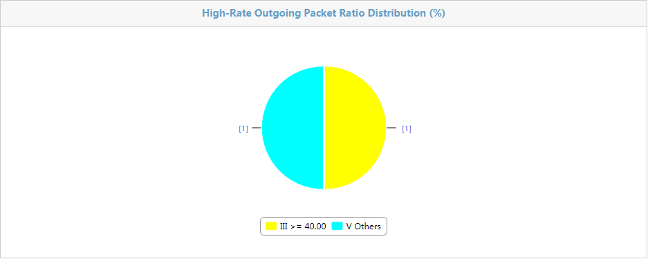
· High-Rate Outgoing Packet Ratio Distribution—Displays the high-rate incoming packet ratio distribution of the evaluated APs, as shown in Figure 93.
Figure 93 High-Rate Incoming Packet Ratio Distribution
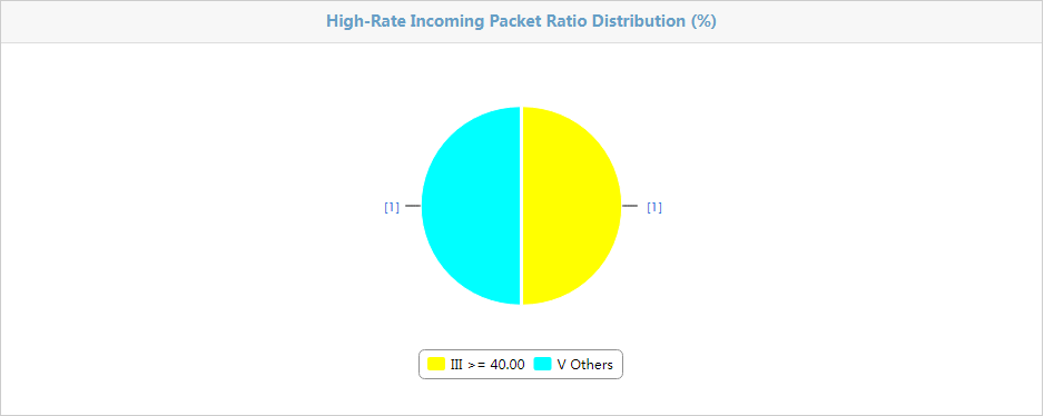
· AP Association Failure Reason Distribution—Displays association failure reasons for all APs, including associated client upper limit reached, unsupported mandatory rate, eassociation failure, o thers (such as weak signal strength and blacklist), and unknown reason.as shown in Figure 94.
Figure 94 AP Association Failure Reason Distribution
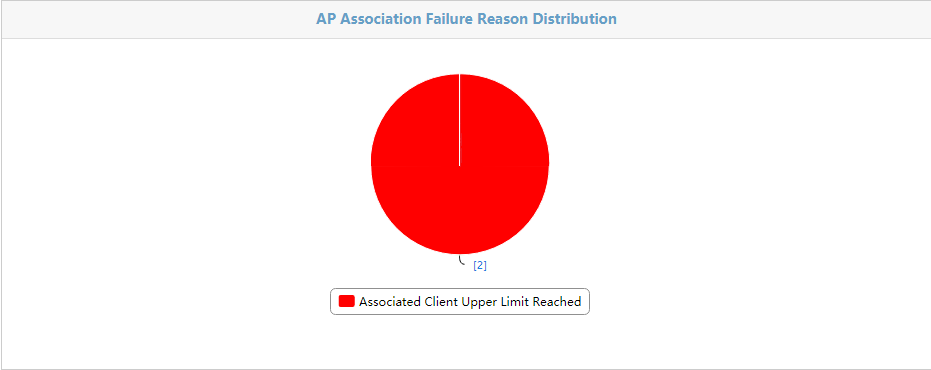
· Client Signal Strength Distribution—Displays the signal strength distribution for all clients associated with the APs in the location, as shown in Figure 95.
Figure 95 Client Signal Strength Distribution
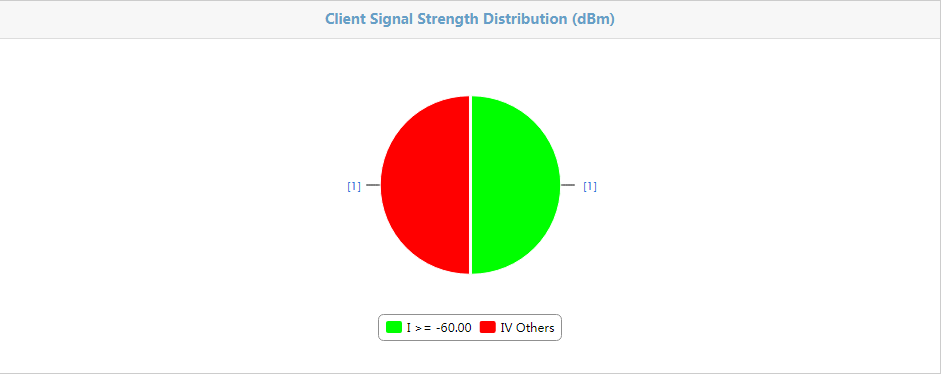
· Average Number of Online Clients Distribution—Displays the signal strength distribution for all clients associated with the APs in the location, as shown in Figure 96.
Figure 96 Average Number of Online Clients Distribution

· Client Dropping Ratio Distribution—Displays the dropping ratio of clients associated with the APs in the location, as shown in Figure 97.
Figure 97 Client Dropping Ratio Distribution
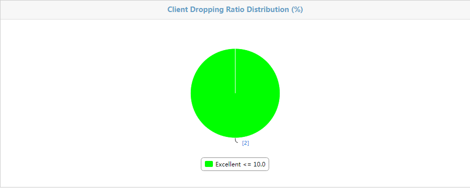
Viewing AP evaluation information
You can view both the history and overall evaluation information only for a completed or expired evaluation task, and can only view the AP history evaluation information for evaluation tasks in other states.
Overall AP evaluation information
The data on the device list is displayed in different colors according to the configured thresholds. Green represents excellent, red represents poor, and black represents other levels. To set thresholds, see "Setting global thresholds" or "Setting thresholds for an evaluation task."
Device List contents
· AP Label—Label of the AP. Click the label link to view its details.
· Average Number of Online Clients—Average number of online clients of the AP.
· Average Transmission Rate (Mbps)—Average transmission rate of the AP.
· Average Receive Rate (Mbps)—Average reception rate of the AP.
· High-Rate Outgoing Packet Ratio (%)—Average high-rate packet ratio for transmitted packets of each AP in the location.
· High-Rate Incoming Packet Ratio (%)—Average high-rate packet ratio for received packets of each AP in the location.
· Association Success Ratio—Number of successful associations of clients in the location to the total number of associations (in percentages).
· Incoming Packet Error Ratio (%)—Average error packet ratio for received packets of each AP in the location.
· Client Dropping Ratio (%)—Average dropping ratio for each terminal on APs in the location.
· Evaluation Result—Evaluation result of the AP.
If the Device List contains enough entries, the following navigational aids are displayed:
· Click the Next Page
icon ![]() to page
forward in the Device List.
to page
forward in the Device List.
· Click the Last Page icon ![]() to page forward to the end of the Device List.
to page forward to the end of the Device List.
· Click the Previous Page icon ![]() to
page backward in the Device List.
to
page backward in the Device List.
· Click the First Page icon ![]() to
page backward to the front of the Device List.
to
page backward to the front of the Device List.
Click 8, 15, 50, 100, or 200 on the upper right of the Device List to specify the number of items you want to display on each page.
|
|
NOTE: You can sort the Device List by every field except the Operation field. Click the column label to sort the list by the selected field. The column label allows you to toggle between the sort options specific to each field. |
Querying evaluated APs
1. Enter one or more of the following query criteria in the Query Criteria area:
¡ AP Label—Enter the label of the AP. WSM supports fuzzy matching for this field
¡ Evaluation Result—Select Excellent, Good, Fair, or Poor to filter APs.
¡ View History Records—Select this option to view the history evaluation information of the AP. Evaluation Date—Select a date for the evaluation history record. This option is available only when you select View History Records.
¡ Evaluation Indexes—Select an evaluation index, select a match criterion, and enter a value for the criterion. Optional indexes are:
- Average Number of Online Clients
- Average Transmission Rate (Mbps)
- Average Reception Rate (Mbps)
- High-Rate Outgoing Packet Ratio (%)
- High-Rate Incoming Packet Ratio (%)
- Association Success Ratio (%)
- Incoming Packet Error Ratio (%)
- Client Offline Ratio (%)
Optional match criteria are =, >=, >, <=, and <.
An empty field or a field that is set to Unlimited does not serve as a query criterion.
2. Click Query. The Device List displays all APs matching the query criteria.
3. Click Reset to clear the query criteria and display all APs.
Querying history evaluation information for APs
1. Select View History Records in the Query Criteria area, select an evaluation date, and set other query criteria as needed. For more information, see "Viewing AP evaluation information."
2. Click Query. The Device List displays all APs matching the query criteria.
Device List contents
¡ AP Label—Enter the label of the AP. WSM supports fuzzy matching for this field
¡ Average Number of Online Clients—Average number of online clients of the AP.
¡ Average Transmission Rate (Mbps)—Average transmission rate of the AP.
¡ Average Reception Rate (Mbps)—Average reception rate of the AP.
¡ High-Rate Outgoing Packet Ratio (%)—Average high-rate packet ratio for transmitted packets of each AP in the location.
¡ High-Rate Incoming Packet Ratio (%)—Average high-rate packet ratio for received packets of each AP in the location.
¡ Association Success Ratio—Number of successful associations of clients in the location to the total number of associations (in percentages).
¡ Incoming Packet Error Ratio (%)—Average error packet ratio for received packets of each AP in the location.
¡ Client Offline Ratio (%)—Average offline ratio for each terminal on APs in the location.
¡ Evaluation Date—Evaluation date of the AP.
¡ Evaluation Result—Evaluation result of the AP.
If the Device List contains enough entries, the following navigational aids are displayed:
· Click the Next Page
icon ![]() to page
forward in the Device List.
to page
forward in the Device List.
· Click the Last Page icon ![]() to page forward to the end of the Device List.
to page forward to the end of the Device List.
· Click the Previous Page icon ![]() to
page backward in the Device List.
to
page backward in the Device List.
· Click the First Page icon ![]() to
page backward to the front of the Device List.
to
page backward to the front of the Device List.
Click 8, 15, 50, 100, or 200 on the upper right of the Device List to specify the number of items you want to display on each page.
|
|
NOTE: You can sort the Device List by every field except the Operation field. Click the column label to sort the list by the selected field. The column label allows you to toggle between the various sort options specific to each field. |
Viewing detailed evaluation information for an AP
To view detailed evaluation information for an AP, click the label link for the target AP on the Device List.
Basic Information
· AP Label—Label of the AP.
· Evaluation Result—Evaluation result of the AP.
· IP Address—The management IP address of the AP.
· AP Model—Model of the AP.
· Mask—Mask of the AP.
· Location—Location view to which the AP belongs. Click the name link of the location to enter the overall evaluation page of the location. For more information about overall evaluation, see "Viewing the overall evaluation information."
Packet Statistics
· Average Transmission Rate (Mb/s)—Average AP transmission rate.
· Average Reception Rate (Mb/s)—Average AP reception rate.
· High-Rate Outgoing Packet Ratio (%)—Average high-rate packet ratio for transmitted packets of each AP in the location.
· High-Rate Incoming Packet Ratio (%)—Average high-rate packet ratio for received packets of each AP in the location.
· Association Success Ratio—Number of successful associations of clients in the location to the total number of associations (in percentages).
· Incoming Packet Error Ratio (%)—Average error packet ratio for received packets of each AP in the location.
· Client Dropping Ratio (%)—Average dropping ratio for each client on APs in the location.
Client Information
· Average Number of Online Clients—Average number of online clients of the AP.
· Total Number of Associations—Total number of clients that have been successfully associated with the AP.
· Total Number of Failed Associations—Total number of clients that have failed to associate with the AP.
· Total Number of Rejected Associations—Total number of rejected clients of the AP.
· Total Number of Re-Associated—Total number of clients that have re-associated with the AP.
· Total Number of Abnormal Logouts—Total number of exceptionally de-associated clients of the AP.
· Association Success Ratio (%)—Number of successful associations to the total number of association requests.
· Relevant Blocking Rate (%)—Number of failed associations caused by insufficient resources to the total number of association requests.
Pie Chart
· AP Association Failure Reason Distribution—Displays association failure reasons for all APs, including associated client upper limit reached, unsupported mandatory rate, eassociation failure, o thers (such as weak signal strength and blacklist), and unknown reason., as shown in Figure 98.
Figure 98 AP Association Failure Reason Distribution

· Client Signal Strength Distribution—Displays signal strength distribution for all clients associated with the APs in the location, as shown in Figure 99.
Figure 99 Client Signal Strength Distribution

Device List
Displays history evaluation information for an AP.
Viewing client evaluation information
You can view both the history and overall evaluation information only for a completed or expired evaluation task, and can only view the client history evaluation information for evaluation tasks in other states.
The data on the client list is displayed in different colors according to the configured thresholds. Green represents excellent, red represents poor, and black represents other levels. To set thresholds, see "Setting global thresholds" or "Setting thresholds for an evaluation task."
Client List contents
· MAC Address—MAC address of the client. Click the address link to view detailed evaluation information about the client.
· Username—Name of the client.
· Total Traffic (MB)—Total traffic sent and received by the client.
· Average Transmission Rate (Mb/s)—Average transmission rate of the client.
· Average Reception Rate (Mb/s)—Average reception rate of the client.
· Power Save Mode Percentage—Times that the client operates in power-save mode to the total number of data collection times.
· Average RSSI—Average RSSI of the client.
· High-Rate Outgoing Packet Ratio (%)—Average high-rate packet ratio for transmitted packets of the client.
· High-Rate Incoming Packet Ratio (%)—Average high-rate packet ratio for received packets of the client.
· Evaluation Result—Evaluation result of the AP.
If the Client List contains enough entries, the following navigational aids are displayed:
· Click the Next Page
icon ![]() to page
forward in the Client List.
to page
forward in the Client List.
· Click the Last Page icon ![]() to page forward to the end of the Client List.
to page forward to the end of the Client List.
· Click the Previous Page icon ![]() to
page backward in the Client List.
to
page backward in the Client List.
· Click the First Page icon ![]() to
page backward to the front of the Client List.
to
page backward to the front of the Client List.
Click 8, 15, 50, 100, or 200 on the upper right of the Client List to specify the number of items you want to display on each page.
|
|
NOTE: You can sort the Client List by every field except the Operation field. Click the column label to sort the list by the selected field. The column label allows you to toggle between the various sort options specific to each field. |
Querying clients that have been evaluated
1. Enter one or more of the following query criteria in the Query Criteria area:
¡ Username—Enter the name of the client. WSM supports fuzzy matching for this field.
¡ MAC Address—Enter the MAC address of the client. WSM supports fuzzy matching for this field.
¡ Evaluation Result—Select Excellent, Good, Fair, or Poor to filter clients.
¡ View History Records—Select this option to view the history evaluation information of the AP. Evaluation Date—Select the date of the evaluation history record. This option is available only if you select View History Records.
¡ Evaluation Indexes—Select an evaluation index, select a match criterion, and enter a value for the criterion. Optional indexes are:
- Total Traffic (MB)
- Average Transmission Rate (Mb/s)
- Average Reception Rate (Mb/s)
- Power Save Mode Percentage (%)
- Average RSSI
- High-Rate Outgoing Packet Ratio (%)
- High-Rate Incoming Packet Ratio (%).
Optional match criteria are =, >=, >, <=, and <.
An empty field or a field that is set to Unlimited does not serve as a query criterion.
2. Click Query. The Client List displays all clients matching the query criteria.
3. Click Reset to clear the query criteria and display all clients.
Viewing history evaluation information for clients
1. Select View History Records in the Query Criteria area, select an evaluation date, and set other query criteria as needed.
2. Click Query. The Client List displays all clients matching the query criteria.
The data on the client list is displayed in different colors according to the configured thresholds. Green represents excellent, red represents poor, and black represents other levels. To set thresholds, see "Setting global thresholds" or "Setting thresholds for an evaluation task."
Client List contents
¡ MAC Address—MAC address of the client. Click the address link to view detailed evaluation information for the client.
¡ Username—Name of the client.
¡ Total Traffic (MB)—Total traffic sent and received by the client.
¡ Average Transmission Rate (Mb/s)—Average transmission rate of the client.
¡ Average Reception Rate (Mb/s)—Average reception rate of the client.
¡ Power Save Mode Percentage (%)—Times that the client operates in power save mode to the total number of data collection times.
¡ Average RSSI—Average RSSI of the client.
¡ High-Rate Outgoing Packet Ratio (%)—Average high-rate packet ratio for transmitted packets of the client.
¡ High-Rate Incoming Packet Ratio (%)—Average high-rate packet ratio for received packets of the client.
¡ Evaluation Date—Evaluation date of the client.
¡ Evaluation Result—Evaluation result of the client.
If the Client List contains enough entries, the following navigational aids are displayed:
· Click the Next Page
icon ![]() to page
forward in the Client List.
to page
forward in the Client List.
· Click the Last Page icon ![]() to page forward to the end of the Client List.
to page forward to the end of the Client List.
· Click the Previous Page icon ![]() to
page backward in the Client List.
to
page backward in the Client List.
· Click the First Page icon ![]() to
page backward to the front of the Client List.
to
page backward to the front of the Client List.
Click 8, 15, 50, 100, or 200 at the upper right of the Client List to specify the number of items you want to display on each page.
|
|
NOTE: You can sort the Client List by every field except the Operation field. Click the column label to sort the list by the selected field. The column label allows you to toggle between the various sort options specific to each field. |
Viewing detailed evaluation information for a client
To query detailed evaluation for a client, click the MAC address link for the target client on the Client List.
The data is displayed in different colors according to the configured thresholds. Green represents excellent, red represents poor, and black represents other levels. To set thresholds, see "Setting global thresholds" or "Setting thresholds for an evaluation task."
Details
Displays basic information and evaluation information for clients.
· Signal Noise Ratio—Signal-to-noise ratio of the client.
· Average Signal Strength (dBm)—Average signal strength of the client.
· AP Outgoing Packet Loss Ratio (%)—Average packet loss ratio of the packets received by the client.
· Incoming Packet Error Ratio (%)—Average error packet ratio of the packets received by the client.
· Packet Retransmission Ratio—Average packet retransmission rate of the client.
Other parameters are the same as overall evaluation information. For more information, see "Viewing the client online history information list."
History Records
Displays history evaluation information for clients. For more information, see "Querying client online history information."
Viewing radio evaluation information
Radio evaluation information includes transmitted traffic of a radio, channel packet error ratio, and channel packet utilization ratio. You can get the operating status of the radio by viewing the evaluation information.
To view radio evaluation information, click the Radio tab.
Radio List contents
· Radio ID—Radio ID.
· Radio Type—Type of the radio. Options are 11a, 11b, 11g, 11n, 11gn, and 11an.
· AP Label—Label of the AP to which the radio belongs.
· Tx. Unicasts (MB)—Transmitted unicast traffic.
· Tx. Multicasts/Broadcasts (MB)—Transmitted multicast and broadcast traffic.
· Tx. Traffic (MB)—Total transmitted traffic.
· Rx. Unicasts (MB)—Received unicast traffic.
· Rx. Multicasts/Broadcasts (MB)—Received multicast and broadcast traffic.
· Rx. Traffic (MB)—Total received traffic.
· Channel Packet Error Ratio (%)—Packet error ratio of the working channel.
· Channel Usage (%)—Utilization ratio of the working channel.
If the Radio List contains enough entries, the following navigational aids are displayed:
· Click the Next Page
icon ![]() to page
forward in the Radio List.
to page
forward in the Radio List.
· Click the Last Page icon ![]() to page forward to the end of the Radio List.
to page forward to the end of the Radio List.
· Click the Previous Page icon ![]() to
page backward in the Radio List.
to
page backward in the Radio List.
· Click the First Page icon ![]() to
page backward to the front of the Radio List.
to
page backward to the front of the Radio List.
Click 8, 15, 50, 100, or 200 at the upper right of the Radio List to specify the number of items you want to display on each page.
|
|
NOTE: You cannot sort the Radio List by every field. |
Querying evaluated radios
WSM provides basic query and advanced query. Basic query uses radio ID as the only criterion for quick searches. Advanced query offers various query criteria for precise matching.
Basic query
1. Click the Radio tab.
2. Enter the radio ID in the query field on the top right corner.
3. Click the Query
icon ![]() . The
radio list displays evaluation information for all radios matching the
criterion.
. The
radio list displays evaluation information for all radios matching the
criterion.
Advanced query
1. Click the Radio tab.
2. Click the Expand
icon ![]() .
.
Set query criteria as follows:
¡ AP Label—Enter the label of the AP to which the radio belongs. WSM supports fuzzy matching for this field.
¡ Radio Type—Select the radio type. Options include Unlimited, 11a, 11b, 11g, 11n, 11gn, 11an.
¡ View History Records—Select whether to view history records. You can view all history records or the history records of a day. Data collected every 15 minutes forms a record. You need to select the evaluation date if you select this option.
¡ Evaluation Date—If you select the View History Records option, select a date to view history records of the day, or select Unlimited to view all history records.
¡ Radio ID—Enter the radio ID.
¡ Evaluation Indexes—Set an evaluation index for the query. For example, you can view evaluation information of radios whose channel utilization ratio is less than 20%. This query criterion has three parts: evaluation index, comparison operator, and value.
The evaluation indexes include:
- Tx. Traffic (MB)
- Rx. Traffic (MB)
- Channel Packet Error Ratio (%)
- Channel Usage (%)
The comparison operators include:
- Equal sign (=)
- Right angle bracket and equal sign (>=)
- Right angle bracket (>)
- Left angle bracket and equal sign (<=)
- Left angle bracket (<)
3. Click Query. The radio list displays evaluation information for all radios matching the criteria.
4. Click Reset to clear all criteria. The radio list displays evaluation information for all radios.
Viewing channel evaluation information
You can view channel utilization ratio through channel evaluation information.
To view channel evaluation information, click the Channel tab.
Channel list contents
· Radio Type—Type of the radio operating on this channel.
· AP Label—Label of the AP to which the radio belongs.
· IP Address—IP address of the AP.
· Radio ID—Radio ID.
· Channel—Channel.
· Channel Bandwidth (MHz)—Channel bandwidth, 22 MHz or 44 MHz.
· Avg. Channel Usage (%)—Average channel utilization.
· Avg. Packet Rx. Channel Usage (%)—Average utilization for packet reception on the channel.
· Avg. Packet Tx. Channel Usage (%)—Average utilization for packet transmission on the channel.
If the Channel List contains enough entries, the following navigational aids are displayed:
· Click the Next Page
icon ![]() to page
forward in the Channel List.
to page
forward in the Channel List.
· Click the Last Page icon ![]() to page forward to the end of the Channel List.
to page forward to the end of the Channel List.
· Click the Previous Page icon ![]() to
page backward in the Channel List.
to
page backward in the Channel List.
· Click the First Page icon ![]() to
page backward to the front of the Channel List.
to
page backward to the front of the Channel List.
Click 8, 15, 50, 100, or 200 at the upper right of the Channel List to specify the number of items you want to display on each page.
|
|
NOTE: You cannot sort the Channel List by every field. |
Querying evaluated channels
WSM provides basic query and advanced query. Basic query uses channel as the only criterion for quick searches. Advanced query offers various query criteria for precise matching.
Basic query
1. Click the Channel tab.
2. Enter the channel number in the query field on the top right corner.
3. Click the Query
icon ![]() . The
channel list displays evaluation information for the channel matching the query
criterion.
. The
channel list displays evaluation information for the channel matching the query
criterion.
Advanced query
1. Click the Channel tab.
2. Click the Expand
icon ![]() to the right of the query field.
to the right of the query field.
Set query criteria as follows:
¡ AP Label—Enter the AP label. WSM supports fuzzy matching for this field.
¡ Channel—Enter the channel number. WSM supports fuzzy matching for this field.
¡ View History Records—Select whether to view history records. You can view all history records or the history records of a day. Data collected every 15 minutes forms a record. You need to select the evaluation date if you select this option.
¡ Evaluation Date—If you select the View History Records option, select a date to view history records of the day, or select Unlimited to view all history records.
¡ AP Channel Analysis—Set an evaluation index for the query. For example, you can view evaluation information for channels whose utilization ratio is less than 20%. This query criterion has three parts: evaluation index, comparison operator, and value.
The evaluation indexes include:
- Avg. Channel Usage (%)
- Avg. Packet Rx. Channel Usage (%)
- Avg. Packet Tx. Channel Usage (%)
The comparison operators include:
- Equal sign (=)
- Right angle bracket and equal sign (>=)
- Right angle bracket (>)
- Left angle bracket and equal sign (<=)
- Left angle bracket (<)
3. Click Query. The channel list displays evaluation information of all channels matching the criteria.
4. Click Reset to clear all criteria. The channel list displays evaluation information of all channels.
Wireless service reports
WSM reports display WSM service statistics by table and graph.
WSM has predefined a number of realtime reports and scheduled reports. Operators can also customize reports. To customize reports, you must use the IMC iAR component.
· Realtime report—Enables operators to view the current statistics or statistics over a specific time range about devices, clients, and services, and to print reports or save them to the WSM server for later viewing and downloading.
· Scheduled report—Enables operators to predefine the generation period and report template. Operators can view reports generated in different periods for data comparison and trend analysis. WSM supports sending reports to the operator by email.
The basic functions such as adding shortcuts, modifying, deleting, and exporting or printing WSM reports are the same as IMC platform reports. This document describes only the functions of adding scheduled reports and viewing realtime/scheduled reports. For basic report operations, see H3C IMC v7.3 Enterprise and Standard Platform Administrator Guide.
Realtime reports
Realtime reports enable operators to view the current statistics or statistics over a specific time range.
Viewing a realtime report
1. Click the Report tab.
2. From the navigation tree, select Reports > Report Template List to enter the Report Template List page.
3. In the Query Template area, select Wireless Service Report from the Type list, and click Query.
The Report Template List displays all the wireless service reports.
4. Click the link naming the report template you want to view.
The page for configuring parameters for generating the report opens.
5. Configure the required parameters, and then click OK.
The parameters vary with report templates. The following information describes the parameters required for viewing each report and the report content.
AC statistics report
To view an AC statistics report, configure the following parameters:
· Parameter "Begin Time and End Time"—Select a statistics collection time range from the list. You can select a specific time range, such as Last Hour, Last Day, Last Week, or Last Month, or select Custom Range, and then specify the start time and end time manually.
· Begin Time/End Time—These two parameters appear only when you select Custom Range. Click the field next to Begin Time/End Time to select the start time/end time from the calendar that appears, in the YYYY-MM-DD hh:mm format. The end time must be later than the start time.
AC statistics report fields:
· Report Period—Time range during which the statistics were collected.
· AC Name—Name of the AC.
· IP Address—IPv4 address of the AC.
· AP Number—Total number of APs managed by the AC.
· Online/M APs—Number of master APs managed by the AC.
· Online/B APs—Number of backup online APs managed by the AC.
· Availability (%)—Percentage of time the APs managed by the AC are available.
· Busy APs—Number of busy APs managed by the AC. An AP is considered busy when its associated client number or transmission rate reaches the specified threshold. For more information, see "Busy AP statistics report."
· Idle APs—Number of idle APs managed by the AC. An AP is considered idle when its associated client number or transmission rate is equal to or below the specified threshold. For information about, see "Idle AP statistics report."
· Worst APs—Number of worst APs managed by the AC. An AP is considered as worst when its out-of-service rate or association congestion rate reaches the specified threshold.
· Transmitted Traffic (MB)—Total traffic transmitted by the AC.
· Received Traffic (MB)—Total traffic received by the AC.
· Packet Retransmit Ratio (%)—Ratio of the number of retransmitted packets to the total number of transmitted packets.
· Error Frame Ratio (%)—Ratio of the number of error frames to the total number of frames received by the AC.
· Max Transmit Speed (Mb/s)—Maximum transmission speed of the AC.
· Avg Transmit Speed (Mb/s)—Average transmission speed of the AC.
· Max Receive Speed (Mb/s)—Maximum reception speed of the AC.
· Avg Receive Speed (Mb/s)—Average reception speed of the AC.
· Max Online Client Number—Maximum number of online clients on the AC.
· Avg Online Client Number—Average number of online clients on the AC.
· AP Average Utilization (%)—Average use of the fit APs managed by the AC, calculated as Avg Online Client Number/X, where X is the AP usage value specified in the configuration file.
· AP Peak Utilization (%)—Peak use of the fit APs managed by the AC, calculated as Max Online Client Number/X, where X is the AP usage value specified in the configuration file.
· Total Client Online Duration—Total online duration of the clients.
· Avg Client Online Duration—Average online duration of the clients.
· Successful Accesses—Total number of times the clients have associated successfully with the APs managed by the AC.
· Success Rate (%)—Ratio of successful accesses to the total number of access requests.
· Association Congestion Rate (%)—Client association congestion rate of the AC, which is the ratio of association failures to the total number of association requests.
· Client Dropping Rate (%)—Client dropping rate of the AC, which is the ratio of client abnormal logouts to the total number of online clients.
AP association summary report
This report displays the summary client association statistics for all APs or APs in a location view. If the location view has sublocations, the report also displays the summary and top 10 client association statistics for the location view and its sublocations.
To view an AP association summary report, configure the following parameters:
· Parameter "Begin Time and End Time"—Select a statistics collection time range from the list. You can select a specific time range, such as Last Hour, Last Week, or Last Month, or select Custom Range, and then specify the start time and end time manually.
· Location—Select a specific location view for statistics collection, or select All AP Devices.
· Begin Time/End Time—These two parameters appear only when you select Custom Range. Click the field next to Begin Time/End Time to select the start time/end time from the calendar that appears, in the YYYY-MM-DD hh:mm format. The end time must be later than the start time.
AP association summary report parameters:
· Report Period—Time range during which the statistics are collected.
· Location—Name of the location view for which the statistics are collected or All AP Devices.
AP association summary report fields:
· Location—Location view name or All AP Devices.
· AP Number—Number of APs contained in the location view or total number of all APs.
· Access Requests—Total number of client access requests.
· Access Responses—Total number of responses sent by the APs to the requesting clients.
· Successful Accesses—Total number of times the clients were associated successfully with the APs.
· Abnormal Logouts—Total number of times the clients associated with the APs were logged out abnormally.
· Client Dropping Rate (%)—Client dropping rate of the APs, which is the ratio of client abnormal logouts to the total number of online clients.
· Success Rate (%)—Client access success rate of the APs, which is the ratio of successful accesses to the total number of access requests.
· Association Congestion Rate (%)—Client association congestion rate of the APs, which is the ratio of association failures to the total number of association requests.
AP association detail report
This report displays the detailed client association statistics for individual APs. With this report, users can learn the access quality of individual APs and the location view to which they belong.
To view an AP association detail report, configure the following parameters:
· Parameter "Begin Time and End Time"—Select a statistics collection time range from the list. You can select a specific time range, such as Last Hour, Last Day, Last Week, or Last Month, or select Custom Range, and then specify the start time and end time manually.
· Location—Select a specific location view for statistics collection, or select All AP Devices.
· Begin Time/End Time—These two parameters appear only when you select Custom Range. Click the field next to Begin Time/End Time to select the start time/end time from the calendar that appears, in the YYYY-MM-DD hh:mm format. The end time must be later than the start time.
AP association detail report parameters:
· Report Period—Time range during which the statistics are collected.
· Location—Name of the location view for which the statistics are collected or All AP Devices.
AP association detail report fields:
· AP Label—Access point name.
· AP Location—Location view to which the AP belongs.
· Access Requests—Total number of client access requests received by the AP.
· Access Responses—Total number of responses sent by the AP to the requesting clients.
· Successful Accesses—Total number of times the clients have successfully associated with the AP.
· Abnormal Logouts—Total number of times the clients associated with the AP are logged out abnormally.
· Client Dropping Rate (%)—Client dropping rate of the AP, which is the ratio of abnormal logouts to the total number of clients associated with the AP.
· Success Rate (%)—Client association success rate of the AP, which is the ratio of successful accesses to the total number of access requests.
· Association Congestion Rate (%)—Client association congestion rate of the AP, which is the ratio of association failures to the total number of association requests.
AP availability summary report
This report displays the summary availability statistics for all APs or APs in a location view. If the location view has sublocations, the report also displays the summary and top 10 availability statistics for the location view and its sublocations.
To view an AP availability summary report, configure the following parameters:
· Parameter "Begin Time and End Time"—Select a statistics collection time range from the list. You can select a specific time range, such as Last Hour, Last Day, Last Week, or Last Month, or select Custom Range, and then specify the start time and end time manually.
· Location—Select a specific location view for statistics collection, or select All AP Devices.
· Begin Time/End Time—These two parameters appear only when you select Custom Range. Click the field next to Begin Time/End Time to select the start time/end time from the calendar that appears, in the YYYY-MM-DD hh:mm format. The end time must be later than the start time.
AP availability summary report parameters:
· Report Period—Time range during which the statistics were collected.
· Location—Name of the location view for which the statistics are collected or All AP Devices.
AP availability summary report fields:
· Availability Highest Top 10—Displays the top 10 location views with the highest availability in a bar chart.
· Availability Lowest Top 10—Displays the top 10 location views with the lowest availability in a bar chart.
· Location—Location view name or All AP Devices.
· AP Number—Total number of APs.
· Total Unavailable Time—Total unavailable time of the APs.
· Total Available Time—Total available time of the APs.
· Availability—Percentage of time the APs are available.
AP availability detail report
This report displays detailed availability statistics for individual APs.
To view an AP availability detail report, configure the following parameters:
· Parameter "Begin Time and End Time"—Select a statistics collection time range from the list. You can select a specific time range, such as Last Hour, Last Day, Last Week, or Last Month, or select Custom Range, and then specify the start time and end time manually.
· Location—Select a specific location view for statistics collection, or select All AP Devices.
· Begin Time/End Time—These two parameters appear only when you select Custom Range. Click the field next to Begin Time/End Time to select the start time/end time from the calendar that appears, in the YYYY-MM-DD hh:mm format. The end time must be later than the start time.
AP availability detail report fields:
· Report Period—Time range during which the statistics are collected.
· Location—Name of the location view for which the statistics are collected or All AP Devices.
· AP Name—Access point name.
· AP Location—Location view to which the AP belongs.
· IP Address—IPv4 address of the AP.
· Model—AP model.
· Available Time—Total time the AP is available.
· Unavailable Time—Total time the AP is unavailable.
· Availability—Percentage of time the AP is available.
AP traffic summary report
This report displays the summary traffic statistics for all APs or APs in a location view. If the location view has sublocations, the report also displays the summary traffic statistics for the sublocations and the top 10 location views with the highest wired/wireless traffic volumes. These statistics help with capacity planning for future scalability needs.
To view an AP traffic summary report, configure the following parameters:
· Parameter "Begin Time and End Time"—Select a statistics collection time range from the list. You can select a specific time range, such as Last Hour, Last Day, Last Week, or Last Month, or select Self-Defined, and then specify the start time and end time manually.
· Location—Select a specific location view for statistics collection, or select All AP Devices.
· Begin Time/End Time—These two parameters appear only when you select Custom Range. Click the field next to Begin Time/End Time to select the start time/end time from the calendar that appears, in the YYYY-MM-DD hh:mm format. The end time must be later than the start time.
AP traffic summary report parameters:
· Report Period—Time range during which the statistics are collected.
· Position—Name of the location view for which the statistics are collected or All AP Devices.
AP traffic summary report graphs:
· Core Traffic Top 10—Displays the top 10 location views with the highest wired traffic volumes in a bar chart.
· Radio Traffic Top 10—Displays the top 10 location views with the highest wireless traffic volumes in a bar chart.
· Core Traffic Trend
· Radio Traffic Trend
· Position—Location view name or All AP Devices.
· AP Number—Number of APs contained in the location view or total number of all APs.
· Core Frames Reception—Total number of frames received by the APs from the wired network.
· Core Errors Reception—Total number of error packets received by the APs from the wired network.
· Core Traffic Reception (MB)—Total traffic received by the APs from the wired network.
· Core Traffic Transmission (MB)—Total traffic sent by the APs to the wired network.
· Radio Frames Reception—Total number of frames received by the APs from the wireless network.
· Radio Errors Reception—Total number of error packets received by the APs from the wireless network.
· Radio Traffic Reception (MB)—Total traffic received by the APs from the wireless network.
· Radio Traffic Transmission (MB)—Total traffic sent by the APs to the wireless network.
AP traffic detail report
This report displays traffic statistics for individual APs and the top 10 APs with the highest wired and wireless traffic volumes. These statistics help with capacity planning for future scalability needs.
To view an AP traffic detail report, configure the following parameters:
· Parameter "Begin Time and End Time"—Select a statistics collection time range from the list. You can select a specific time range, such as Last Hour, Last Day, Last Week, or Last Month, or select Custom Range, and then specify the start time and end time manually.
· Location—Select a specific location view for statistics collection, or select All AP Devices.
· Begin Time/End Time—These two parameters appear only when you select Custom Range. Click the field next to Begin Time/End Time to select the start time/end time from the calendar that appears, in the YYYY-MM-DD hh:mm format. The end time must be later than the start time.
AP traffic detail report parameters:
· Report Period—Time range during which the statistics are collected.
· Location—Name of the location view for which the statistics are collected or All AP Devices.
AP traffic detail report fields:
· Core Traffic Top 10—Displays the top 10 APs with the highest wired traffic volumes in a bar chart.
· Core Traffic Top 10—Displays the top 10 APs with the highest wireless traffic volumes in a bar chart.
· AP Name—Access point name.
· Location—Location view to which the AP belongs.
· IP Address—IPv4 address of the AP.
· Core Frames Reception—Total number of frames received by the AP from the wired network.
· Core Errors Reception—Total number of error packets received by the AP from the wired network.
· Core Bytes Reception—Total number of bytes received by the AP from the wired network.
· Core Bytes Transmission—Total number of bytes sent by the AP to the wired network.
· Radio Frames Reception—Total number of frames received by the AP from the wireless network.
· Radio Errors Reception—Total number of error packets received by the AP from the wireless network.
· Radio Bytes Reception—Total number of bytes received by the AP from the wireless network.
· Radio Bytes Transmission—Total number of bytes sent by the AP to the wireless network.
AP speed report
This report displays the data reception and transmission speeds of individual APs, and depicts in a line graph the overall trends of data reception and transmission speeds using aggregated data of all APs over a given time period.
To view an AP speed report, configure the following parameters:
· Parameter "Begin Time and End Time"—Select a statistics collection time range from the list. You can select a specific time range, such as Last Hour, Last Day, Last Week, or Last Month, or select Custom Range, and then specify the start time and end time manually.
· Location—Select a specific location view for statistics collection, or select All AP Devices.
· Begin Time/End Time—These two parameters appear only when you select Custom Range. Click the field next to Begin Time/End Time to select the start time/end time from the calendar that appears, in the YYYY-MM-DD hh:mm format. The end time must be later than the start time.
AP speed report parameters:
· Report Period—Time range during which the statistics are collected.
· Location—Name of the location view for which the statistics are collected or All AP Devices.
AP speed report fields:
· Trend graph—Displays the changes of Reception Speed, Transmission Speed, and Total Speed of all APs over the specified report period in a line graph. The maximum and average values of the reception speed, transmission speed, and total speed of all APs are displayed on top of the graph.
· AP Label—Label of the fit AP.
· Location—Location view to which the AP belongs.
· Max Reception Speed—Maximum reception speed of the AP.
· Avg Reception Speed—Average reception speed of the AP.
· Max Transmission Speed—Maximum transmission speed of the AP.
· Avg Transmission Speed—Average transmission speed of the AP.
· Max Total Speed—Maximum total speed of the AP.
· Avg Total Speed—Average total speed of the AP.
AP logoff summary report
This report displays the summary logoff statistics for all APs or APs in a location view. If the location view has sublocations, the report also displays the summary and top 10 logoff statistics for the location view and its sublocations.
To view an AP offline summary report, configure the following parameters:
· Parameter "Begin Time and End Time"—Select a statistics collection time range from the list. You can select a specific time range, such as Last Hour, Last Day, Last Week, or Last Month, or select Custom Range, and then specify the start time and end time manually.
· Position—Select a specific location view for statistics collection, or select All AP Devices.
· Begin Time/End Time—These two parameters appear only when you select Custom Range. Click the field next to Begin Time/End Time to select the start time/end time from the calendar that appears, in the YYYY-MM-DD hh:mm format. The end time must be later than the start time.
· Logoff Time (Hour)—Specify an offline duration in hours. The value must be an integer. The report displays the number of times that the AP offline duration reaches the specified value.
AP logoff summary report parameters:
· Report Period—Time range during which the statistics are collected.
· Location—Name of the location view for which the statistics are collected or All AP Devices.
AP offline summary report fields:
· Logoff Count Top 10—Displays the top 10 location views with the highest AP offline counts.
· Count of Logoff (Duration >= 0 Hour) Top 10—Displays the top 10 location views with the highest AP offline counts with a duration that reaches 0 hour, where 0 is the specified Logoff Time.
· Position—Location view name or All AP Devices.
· AP Number—Number of APs contained in the location view or total number of all APs.
· Total Logoff Count—Total offline counts of the APs contained in the location view or of all APs.
· Count of Logoff (Duration >= 0 Hour)—Total number of times the AP offline duration reaches 0 hours, where 0 is the specified for Logoff Time.
· Total Logoff Duration—Total offline duration of the APs contained in the location view or of all APs.
AP logoff detail report
This report displays detailed AP logoff statistics based on specified query criteria.
To view an AP offline detail report, configure the following parameters:
· Parameter "Begin Time and End Time"—Select a statistics collection time range from the list. You can select a specific time range, such as Last Hour, Last Day, Last Week, or Last Month, or select Custom Range, and then specify the start time and end time manually.
· Location—Select a specific location view for statistics collection, or select All AP Devices.
· Begin Time/End Time—These two parameters appear only when you select Custom Range. Click the field next to Begin Time/End Time to select the start time/end time from the calendar that appears, in the YYYY-MM-DD hh:mm format. The end time must be later than the start time.
· Logoff Time (Hour)—Specify an offline duration in hours. The value must be an integer. The report collects statistics only on APs whose offline duration reaches the specified value.
AP logoff detail report fields:
· Report Period—Time range during which the statistics are collected.
· Location—Name of the location view for which the statistics are collected or All AP Devices.
· AP Name—Access point name.
· Location—Location view to which the AP belongs.
· IP Address—IPv4 address of the AP.
· Model—AP model.
· Logoff Time—Time when the AP logged off.
· Recovery Time—Time when the AP recovered.
· Logoff Duration—Logoff duration for the AP.
Radio error report
This report displays the number of error frames received by AP radios.
To view a radio error report, configure the following parameters:
· Parameter "Begin Time and End Time"—Select a statistics collection time range from the list. You can select a specific time range, such as Last Hour, Last Day, Last Week, or Last Month, or select Custom Range, and then specify the start time and end time manually.
· Location—Select a specific location view for statistics collection, or select All AP Devices.
· Begin Time/End Time—These two parameters appear only when you select Custom Range. Click the field next to Begin Time/End Time to select the start time/end time from the calendar that appears, in the YYYY-MM-DD hh:mm format. The end time must be later than the start time.
Radio error report fields:
· Report Period—Time range during which the statistics are collected.
· Location—Name of the location view for which the statistics are collected or All AP Devices.
· AP Name—Access point name.
· Radio ID—Radio ID.
· AP Location—Location view to which the AP belongs.
· FCS Error Frames—Number of FCS error frames received by the AP radio.
· PHY Error Frames—Number of PHY error frames received by the AP radio.
· MIC Error Frames—Number of MIC error frames received by the AP radio.
· Error Ratio—Ratio of the total number of FCS, PHY, and MIC error frames to the total number of frames received by the AP radio.
Radio traffic report
This report displays traffic statistics for AP radios.
To view a radio traffic report, configure the following parameters:
· Parameter "Begin Time and End Time"—Select a statistics collection time range from the list. You can select a specific time range, such as Last Hour, Last Day, Last Week, or Last Month, or select Custom Range, and then specify the start time and end time manually.
· Location—Select a specific location view for statistics collection, or select All AP Devices.
· Begin Time/End Time—These two parameters appear only when you select Custom Range. Click the field next to Begin Time/End Time to select the start time/end time from the calendar that appears, in the YYYY-MM-DD hh:mm format. The end time must be later than the start time.
Radio traffic report fields:
· Report Period—Time range during which the statistics are collected.
· Location—Name of the location view for which the statistics are collected or All AP Devices.
· AP Name—Access point name.
· Radio ID—ID of the radio.
· AP Location—Location view to which the AP belongs.
· Reception (bytes)—Total traffic received by the AP radio.
· Transmission (bytes)—Total traffic transmitted by the AP radio.
· Total Traffic (bytes)—Total traffic received and transmitted by the AP radio.
Radio speed report
This report displays the maximum and average reception and transmission speeds for AP radios.
To view a radio speed report, configure the following parameters:
· Parameter "Begin Time and End Time"—Select a statistics collection time range from the list. You can select a specific time range, such as Last Hour, Last Day, Last Week, or Last Month, or select Custom Range, and then specify the start time and end time manually.
· Location—Select a specific location view for statistics collection, or select All AP Devices.
· Begin Time/End Time—These two parameters appear only when you select Custom Range. Click the field next to Begin Time/End Time to select the start time/end time from the calendar that appears, in the YYYY-MM-DD hh:mm format. The end time must be later than the start time.
Radio speed report fields:
· Report Period—Time range during which the statistics are collected.
· Location—Name of the location view for which the statistics are collected or All AP Devices.
· AP Label—Access point name.
· Radio ID—ID of the radio.
· AP Location—Location view to which the AP belongs.
· Max Reception Speed (bits/s)—Maximum reception speed of the radio.
· Average Reception Speed (bits/s)—Average reception speed of the radio.
· Max Transmission Speed (bits/s)—Maximum transmission speed of the radio.
· Avg Transmission Speed (bits/s)—Average transmission speed of the radio.
Radio resource usage report
This report displays resource usage statistics for AP radios.
To view a radio resource usage report, configure the following parameters:
· Parameter "Begin Time and End Time"—Select a statistics collection time range from the list. You can select a specific time range, such as Last Hour, Last Day, Last Week, or Last Month, or select Custom Range, and then specify the start time and end time manually.
· Location—Select a specific location view for statistics collection, or select All AP Devices.
· Begin Time/End Time—These two parameters appear only when you select Custom Range. Click the field next to Begin Time/End Time to select the start time/end time from the calendar that appears, in the YYYY-MM-DD hh:mm format. The end time must be later than the start time.
Radio resource usage report fields:
· Report Period—Time range during which the statistics are collected.
· Location—Name of the location view for which the statistics are collected or All AP Devices.
· AP Name—Access point name.
· Radio ID—ID of the radio.
· AP Location—Location view to which the AP belongs.
· IP Address—IPv4 address of the AP.
· Model—AP model.
· Usage—Usage ratio of the radio.
Radio channel usage report
This report displays radio channel usage statistics by radio.
To view a radio resource usage report, configure the following parameters:
· Location—Select a specific location view for statistics collection, or select All AP Devices.
The Radio Channel Usage Top 10 graph displays the top 10 radios with the most channel usage. The horizontal axis represents the AP label and radio ID, and the vertical axis represents the channel usage value.
The following are the radio channel usage report fields:
· AP Label—Device label of the AP.
· AP IP—IP address of the AP.
· AP Serial ID—Serial ID of the AP.
· Location—Name of the location view to which the AP belongs.
· Radio ID—ID of the radio.
· Channel Usage—Channel usage of the radio.
Rogue AP history report
This report displays the history records of detected rogue APs by MAC address.
To view a rogue AP history report, configure the following parameters:
· Parameter "Begin Time and End Time"—Select a statistics collection time range from the list. You can select a specific time range, such as Last Hour, Last Day, Last Week, or Last Month, or select Custom Range, and then specify the start time and end time manually.
· Begin Time/End Time—These two parameters appear only when you select Custom Range. Click the field next to Begin Time/End Time to select the start time/end time from the calendar that appears, in the YYYY-MM-DD hh:mm format. The end time must be later than the start time.
Rogue AP history report fields:
· Report Period—Time range during which the statistics are collected.
· MAC Address—MAC address of the rogue AP.
· Vendor—Vendor of the rogue AP.
· SSID—SSID of the rogue AP.
· Max Signal Strength—Maximum signal strength of the rogue AP.
· Channel—Channel used by the rogue AP.
· Detected by—AC that detected the rogue AP.
· Detected AP—Fit AP that discovered the rogue AP.
· Last Discovered Time—Time when the rogue AP was last discovered.
· Status—State of the rogue AP. Options are Attacked and Not Attacked.
Rogue AP report
This report displays all the newly detected rogue APs by MAC address.
No specific parameters are required for viewing a rogue AP report.
Rogue AP report fields:
· MAC Address—MAC address of the rogue AP.
· Vendor—Vendor of the rogue AP.
· SSID—SSID of the rogue AP.
· Max Signal Strength—Maximum signal strength of the rogue AP.
· Channel—Channel used by the rogue AP.
· Detected by—AC that detected the rogue AP.
· Last Discovered Time—Time when the rogue AP was last discovered.
· Attacked Status—State of the rogue AP. Options are Attacked and Not Attacked.
Rogue client history report
This report displays the history records of detected rogue clients by MAC address.
To view a rogue client history report, configure the following parameters:
· Parameter "Begin Time and End Time"—Select a statistics collection time range from the list. You can select a specific time range, such as Last Hour, Last Day, Last Week, or Last Month, or select Custom Range, and then specify the start time and end time manually.
· Begin Time/End Time—These two parameters appear only when you select Custom Range. Click the field next to Begin Time/End Time to select the start time/end time from the calendar that appears, in the YYYY-MM-DD hh:mm format. The end time must be later than the start time.
Rogue client history report fields:
· Report Period—Time range during which the statistics are collected.
· MAC Address—MAC address of the rogue client.
· SSID –
· Vendor—Vendor of the rogue client.
· Max Signal Strength—Maximum signal strength of the rogue client.
· Channel—Channel used by the rogue client.
· Detected by—AC that detected the rogue client.
· Detected AP—Fit AP that detected the rogue client.
· Last Discovered Time—Time when the rogue client was last discovered.
· Attacked Status—State of the rogue client. Options are Attacked and Not Attacked.
Rogue client report
This report displays all the new rogue clients detected for the first time by MAC address.
No specific parameters are required to view a rogue client report.
Rogue client report fields:
· MAC Address—MAC address of the rogue client.
· Vendor—Vendor of the rogue client.
· Max Signal Strength—Maximum signal strength of the rogue client.
· Channel—Channel used by the rogue client.
· Detected by—AC that detected the rogue client.
· Last Discovered Time—Time when the rogue client was last discovered.
· Attacked Status—State of the rogue client. Options are Attacked and Not Attacked.
Current associated client statistics report
This report displays information about the currently associated clients by MAC address and the top 10 clients with the longest associated duration.
To view a current associated client statistics report, configure the following parameter:
· Location—Select a specific location view for statistics collection, or select All AP Devices.
Current associated client statistics report fields:
· Position—Name of the location view for which the statistics are collected or All AP Devices.
· Associated Duration Top 10—Displays the top 10 clients with the longest associated duration by client MAC address.
· MAC Address—MAC address of the associated client.
· Client Name—Name of the associated client.
· IP Address—IP address of the associated client.
· SSID—SSID used by the associated client.
· Channel—Channel used by the associated client.
· AP Name—Access point name with which the client is associated.
· AP Position—Location view to which the AP belongs.
· Session Duration—Current associated duration of the client.
· Received Traffic (MB)—Total traffic received by the associated client.
· Transmitted Traffic (MB)—Total traffic transmitted by the associated client.
· Total Traffic (MB)—Total traffic received and sent by the associated client.
Hotspot statistics report by AP
This report displays statistics about the APs contained in locations that are set as hotspots. If the location has sublocations, the report also displays AP statistics of the sublocations that are set as hotspots.
To view a hotspot statistics report by AP, configure the following parameter:
· Location—Select a specific location view for statistics collection, or select All AP Devices.
Hotspot statistics report by AP fields:
· Location—Name of the location view for which the statistics are collected or All AP Devices.
· myltest—Name of the location view that is set as a hotspot. myltest is a hotspot location view name used in this lab environment. The actual location view name is subject to your specific network environment. This field is empty if no hotspot location view is available.
· test—Name of the location view that is set as a hotspot. test is a hotspot location view name used in this lab environment. The actual location view name is subject to your specific network environment. This field is empty if no hotspot location view is available.
· AP Number—Number of APs contained in the hotspot location view.
· Online AP Number—Number of online APs contained in the hotspot location view.
· AP Name—Name of the access point contained in the hotspot location view.
· Status—State of the AP, Online or Offline.
· Serial ID—Serial ID of the AP.
· Model—Model of the AP.
· IP Address—IPv4 address of the AP.
Wireless asset statistics report
This report displays the asset statistics for the managed wireless devices in WSM in a pie chart.
No specific parameters are required for viewing a wireless asset statistics report.
The pie chart shows the number of assets by device category and the contribution of each device category to the total. To view the device list of a specific asset category, click the slice corresponding to it on the chart.
Client summary report
This report displays the total associated times and duration of clients by MAC address, and the top 10 clients with the longest total associated duration.
To view a client summary report, configure the following parameters:
· Parameter "Begin Time and End Time"—Select a statistics collection time range from the list. You can select a specific time range, such as Last Hour, Last Day, Last Week, or Last Month, or select Custom Range, and then specify the start time and end time manually.
· Location—Select a specific location view for statistics collection, or select All AP Devices.
· Begin Time/End Time—These two parameters appear only when you select Custom Range. Click the field next to Begin Time/End Time to select the start time/end time from the calendar that appears, in the YYYY-MM-DD hh:mm format. The end time must be later than the start time.
· Online Duration—Enter the online duration of the clients to be collected. The report collects statistics about clients who have online durations longer than the specified time.
· Column name—Select a column by which the report is sorted.
· Order—Select the sort order. Options are Ascending and Descending.
Client summary report parameters:
· Report Period—Time range during which the statistics are collected.
· Position—Name of the location view for which the statistics are collected or All AP Devices.
Client summary report fields:
· Total Associated Duration Top 10—Displays the top 10 clients with the longest associated duration.
· MAC Address—MAC address of the client.
· Client Name—Name of the client.
· Online Times—Total number of times the client initiated an online connection.
· Total Associated Duration—Total associated duration of the client.
· Avg Associated Duration—Average associated duration of the client.
· Received Traffic (MB)—Total traffic received by the client.
· Sent Traffic (MB)—Total traffic sent by the client.
· Total Traffic (MB)—Total traffic received and sent by the client.
Client detail report
This report displays detailed association records of clients by MAC address.
To view a client detail report, configure the following parameters:
· Parameter "Begin Time and End Time"—Select a statistics collection time range from the list. You can select a specific time range, such as Last Hour, Last Day, Last Week, or Last Month, or select Custom Range, and then specify the start time and end time manually.
· Location—Select a specific location view for statistics collection, or select All AP Devices.
· Begin Time/End Time—These two parameters appear only when you select Custom Range. Click the field next to Begin Time/End Time to select the start time/end time from the calendar that appears, in the YYYY-MM-DD hh:mm format. The end time must be later than the start time.
· Online Duration—Enter the online duration of clients to be collected. The report collects statistics about clients who have online durations longer than the specified time.
Client detail report fields:
· Report Period—Time range during which the statistics are collected.
· Position—Name of the location view for which the statistics are collected or All AP Devices.
· MAC Address—MAC address of the client.
· Client Name—Name of the client.
· IP Address—IPv4 address of the client.
· Radio Type—Radio type.
· SSID—SSID used by the client.
· AP Name—Name of the AP with which the client is associated.
· Position—Location view to which the AP belongs.
· Online Time—Time at which the client successfully associated with the AP.
· Session Duration—Duration of the client session.
· Received Traffic (MB)—Total traffic received by the client.
· Sent Traffic (MB)—Total traffic sent by the client.
· Total Traffic (MB)—Total traffic received and sent by the client.
Client number trendline report
This report provides both the summary and detailed client association statistics for all APs or APs in a location view. It displays the overall trend of associated client number changes using the aggregated data of all APs, as well as the detailed statistics for individual APs.
To view a client number trendline report, configure the following parameters:
· Parameter "Begin Time and End Time"—Select a statistics collection time range from the list. You can select a specific time range, such as Last Hour, Last Day, Last Week, or Last Month, or select Custom Range, and then specify the start time and end time manually.
· Location—Select a specific location view for statistics collection, or select All AP Devices.
· Begin Time/End Time—These two parameters appear only when you select Custom Range. Click the field next to Begin Time/End Time to select the start time/end time from the calendar that appears, in the YYYY-MM-DD hh:mm format. The end time must be later than the start time.
· Column name—Select the column by which the report is sorted.
· Order—Select the sort order. Options are Ascending and Descending.
Client number trendline report parameters:
· Report Period—Time range during which the statistics are collected.
· Location—Name of the location view for which the statistics are collected or All AP Devices.
Client number trendline report fields:
· Global Statistics—Displays changes of the total number of clients associated with all the APs over the specified report period in a line graph. The Max online client number and Avg online client number located at the upper left of the graph shows the maximum and average numbers of clients associated with all APs.
· AP Name—Access point name.
· Location—Location view to which the AP belongs.
· Max Online Client Number—Maximum number of clients associated with the AP.
· Avg Online Client Number—Average number of clients associated with the AP.
· Total Client Associated Duration—Total associated duration of the clients.
· Avg Client Associated Duration—Average associated duration of the clients.
· AP Peak Utilization (%)—Peak use of the AP, calculated as Max Online Client Number/X, where X is AP usage value specified in the configuration file.
Busy AP statistics report
This report displays statistics about the APs with the highest total usage, including the AP's peak online client number, peak transmission rate, out-of-service rate, association congestion rate, and client dropping rate.
To view a busy AP statistics report, configure the following parameters:
· Parameter "Begin Time and End Time"—Select a statistics collection time range from the list. You can select a specific time range, such as Last Hour, Last Day, Last Week, or Last Month, or select Custom Range, and then specify the start time and end time manually.
· Location—Select a specific location view for statistics collection, or select All AP Devices.
· Begin Time/End Time—These two parameters appear only when you select Custom Range. Click the field next to Begin Time/End Time to select the start time/end time from the calendar that appears, in the YYYY-MM-DD hh:mm format. The end time must be later than the start time.
· Peak Number of Online Clients—Specifies the peak number of online client threshold for the AP. An AP is considered busy when its online client count reaches the specified threshold. The default is 20. Click Save to save it as the default value.
· Peak Transmission Rate—Specifies the peak transmission rate threshold for the AP, in Mb/s. An AP is considered busy when its transmission rate reaches the specified threshold. The default is 6 Mb/s. Click Save to save it as the default value.
The Peak Number of Online Clients and Peak Transmission Rate conditions for determining busy APs are in "OR" relations. That is, an AP is considered busy as long as it meets either condition. Click Save next to Peak Number of Online Clients and Peak Transmission Rate to save the current settings as the default for subsequent accesses.
· Column name—Select the column by which the report is sorted.
· Order—Select the sort order. Options are Ascending and Descending.
Busy AP statistics report fields:
· Report Period—Time range during which the statistics are collected.
· Location—Name of the location view for which the statistics are collected or All AP Devices.
· AP Name—Access point name.
· AP Location—Location view to which the AP belongs.
· Peak Number of Online Clients—Maximum number of clients associated with the AP.
· Peak Transmission Rate (Mbps)—Maximum transmission rate of the AP.
· Out of Service Rate (%)—Percentage of time the AP is unavailable.
· Association Congestion Rate (%)—Association congestion rate of the AP, which is the ratio of client association failures to the total number of association requests.
· Client Dropping Rate (%)—Client dropping rate of the AP, which is the ratio of abnormal logoffs to the total number of clients associated with the AP.
Idle AP statistics report
This report displays statistics about the APs with the lowest total usage, including the peak online client number, peak transmission rate, out-of-service rate, association congestion rate, and client dropping rate.
To view an idle AP statistics report, configure the following parameters:
· Parameter "Begin Time and End Time"—Select a statistics collection time range from the list. You can select a specific time range, such as Last Hour, Last Day, Last Week, or Last Month, or select Custom Range, and then specify the start time and end time manually.
· Location—Select a specific location view for statistics collection, or select All AP Devices.
· Begin Time/End Time—These two parameters appear only when you select Custom Range. Click the field next to Begin Time/End Time to select the start time/end time from the calendar that appears, in the YYYY-MM-DD hh:mm format. The end time must be later than the start time.
· Peak Number of Online Clients—Specify the peak number of online clients threshold for the AP. An AP is considered idle when its online client number is equal to or below the specified threshold. The default is 0. Click Save to save it as the default value.
· Peak Transmission Rate—Specify the maximum transmission rate threshold for the AP, in Mb/s. An AP is considered idle when its transmission rate is equal to or below the specified threshold. The default is 1 Mb/s. Click Save to save it as the default value.
The Peak Number of Online Clients and Peak Transmission Rate conditions for determining idle APs are in "OR" relations. That is, an AP is considered idle as long as it meets either condition. Click Save next to Peak Number of Online Clients and Peak Transmission Rate to save the current settings as the default for subsequent accesses.
· Column name—Select the column by which the report is sorted.
· Order—Select the sort order. Options are Ascending and Descending.
Idle AP statistics report fields:
· Report Period—Time range during which the statistics are collected.
· Location—Name of the location view for which the statistics are collected or All AP Devices.
· AP Name—Access point name.
· AP Location—Location view to which the AP belongs.
· Peak Number of Online Clients—Maximum number of clients associated with the AP.
· Peak Transmission Rate (Mbps)—Maximum transmission rate of the AP.
· Out of Service Rate (%)—Percentage of time the AP is unavailable.
· Association Congestion Rate (%)—Association congestion rate of the AP, which is the ratio of client association failures to the total number of association requests.
Worst AP statistics report
This report displays statistics about the worst APs, including the peak online client number, peak transmission rate, out-of-service rate, association congestion rate, and client dropping rate.
To view a worst AP statistics report, configure the following parameters:
· Parameter "Begin Time and End Time"—Select a statistics collection time range from the list. You can select a specific time range, such as Last Hour, Last Day, Last Week, or Last Month, or select Custom Range, and then specify the start time and end time manually.
· Location—Select a specific location view for statistics collection, or select All AP Devices.
· Begin Time/End Time—These two parameters appear only when you select Custom Range. Click the field next to Begin Time/End Time to select the start time/end time from the calendar that appears, in the YYYY-MM-DD hh:mm format. The end time must be later than the start time.
· Out of Service Rate—Specify the out-of-service rate threshold for the AP. An AP is classified as a worst AP when its out-of-service rate reaches the specified threshold. Click Save to save it as the default value.
· Relevant Blocking Rate—Specify the relevant blocking rate threshold for the AP. An AP is considered as worst when its relevant blocking rate is equal to or greater than the specified threshold. The value range is 0.0 to 100.0, and the default is 5%. Click Save to save it as the default value.
· Dropping Rate—Specify the dropping rate threshold for the AP. An AP is considered as worst when its dropping rate reaches the specified threshold. The value range is 0.0 to 100.0, and the default is 3%. If you enter "-1", the parameter is not used as a condition for generating the worst AP statistics report. Click Save to save it as the default value.
The Out of Service Rate, Relevant Blocking Rate, and Dropping Rate conditions for determining a worst AP are in "OR" relations. That is, an AP is considered as worst as long as it meets any of the three conditions. Click Save next to Out of Service Rate, Relevant Blocking Rate, and Dropping Rate to save the current settings as the default for subsequent accesses.
Worst AP statistics report fields:
· Report Period—Time range during which the statistics are collected.
· Position—Location view name or All AP Devices.
· AP Name—Access point name.
· AP Location—Location view to which the AP belongs.
· Peak Number of Online Clients—Maximum number of clients associated with the AP.
· Peak Transmission Rate (Mbps)—Maximum transmission rate of the AP.
· Out of Service Rate (%)—Percentage of time the AP is unavailable.
· Association Congestion Rate (%)—Association congestion rate of the AP, which is the ratio of client association failures to the total number of association requests.
· Client Dropping Rate (%)—Client dropping rate of the AP, which is the ratio of abnormal logoffs to the total number of clients associated with the AP.
AP statistics report
To view an AP statistics report, configure the following parameters:
· Parameter "Begin Time and End Time"—Select a statistics collection time range from the list. You can select a specific time range, such as Last Hour, Last Day, Last Week, or Last Month, or select Custom Range, and then specify the start time and end time manually.
· Location—Select a specific location view for statistics collection, or select All AP Devices.
· Begin Time/End Time—These two parameters appear only when you select Custom Range. Click the field next to Begin Time/End Time to select the start time/end time from the calendar that appears, in the YYYY-MM-DD hh:mm format. The end time must be later than the start time.
· Column name—Select the column by which the report is sorted.
· Order—Select the sort order. Options are Ascending and Descending.
AP statistics report fields:
· Report Period—Time range during which the statistics are collected.
· Location—Name of the location view for which the statistics are collected or All AP Devices.
· AP Name—Access point name.
· Location—Location view to which the AP belongs.
· Availability (%)—Percentage of time the AP is available.
· Transmitted Core Traffic (MB)—Total traffic sent by the AP to the wired network.
· Received Core Traffic (MB)—Total traffic received by the AP from the wired network.
· Transmitted Radio Traffic (MB)—Total traffic sent by the AP to the wireless network.
· Received Radio Traffic (MB)—Total traffic received by the AP from the wireless network.
· Packet Retransmit Ratio (%)—Ratio of retransmitted packets to the total number of packets transmitted by the AP.
· Error Frame Ratio (%)—Ratio of error frames to the total number of frames received by the AP.
· Max Transmit Speed (Mb/s)—Maximum transmission rate of the AP.
· Avg Transmit Speed (Mb/s)—Average transmission speed of the AP.
· Max Receive Speed (Mb/s)—Maximum reception speed of the AP.
· Avg Receive Speed (Mb/s)—Average reception speed of the AP.
· Max Online Client Number—Maximum number of clients associated with the AP.
· Avg Online Client Number—Average number of clients associated with the AP.
· AP Average Utilization (%)—Average use of the AP, calculated as Avg Online Client Number/X, where X is AP usage value specified in the configuration file.
· AP Peak Utilization (%)—Peak use of the AP, calculated as Max Online Client Number/X, where X is the AP usage value specified in the configuration file.
· Total Client Online Duration—Total online duration of the clients associated with the AP.
· Avg Client Online Duration—Average online duration of the clients associated with the AP.
· Successful Accesses—Total number of times the clients have successfully associated with the AP.
· Success Rate (%)—Client access success rate of the AP, which is the ratio of successful accesses to the total number of access requests made by the clients.
· Association Congestion Rate (%)—Client association congestion rate of the AP, which is the ratio of association failures to the total number of client association requests.
· Client Dropping Rate (%)—Client dropping rate of the AP, which is the ratio of abnormal logoffs to the total number online clients associated with the AP.
SSID Online Client Number Statistics Report
This report displays the maximum online client number and the average online client number by SSID.
To view an SSID online client number statistics report, configure the following parameters:
· Parameter "Begin Time and End Time"—Select a statistics collection time range from the list. You can select a specific time range, such as Last Hour, Last Day, Last Week, or Last Month, or select Custom Range, and then specify the start time and end time manually.
· Begin Time/End Time—These two parameters appear only when you select Custom Range. Click the field next to Begin Time/End Time to select the start time/end time from the calendar that appears, in the YYYY-MM-DD hh:mm format. The end time must be later than the start time.
SSID online client number statistics report fields:
· Report Period—Time range during which the statistics are collected.
· SSID—Service set identifier.
· Max Online Client Number—Maximum number of clients associated with the APs that use the SSID.
· Avg Online Client Number—Average number of clients associated with the APs that use the SSID.
SSID statistics report
This report displays the summary AP traffic and online client statistics by SSID.
To view an SSID statistics report, configure the following parameters:
· Parameter "Begin Time and End Time"—Select a statistics collection time range from the list. You can select a specific time range, such as Last Hour, Last Day, Last Week, or Last Month, or select Custom Range, and then specify the start time and end time manually.
· Location—Select a specific location view for statistics collection, or select All AP Devices.
· Begin Time/End Time—These two parameters appear only when you select Custom Range. Click the field next to Begin Time/End Time to select the start time/end time from the calendar that appears, in the YYYY-MM-DD hh:mm format. The end time must be later than the start time.
SSID statistics report fields:
· Report Period—Time range during which the statistics are collected.
· Location—Name of the location view for which the statistics are collected or All AP Devices.
· SSID—Service set identifier.
· Transmitted Radio Traffic (MB)—Total traffic transmitted by the APs that use SSID.
· Received Radio Traffic (MB)—Total traffic received by the APs that use the SSID.
· Max Online Client Number—Maximum number of clients associated with the APs that use the SSID.
· Avg Online Client Number—Average number of clients associated with the APs that use the SSID.
· Availability (%)—Percentage of time the APs that use the SSID are available.
Hotspot statistics report by hotspot
This report displays the location views that are set as hotspots.
To view a hotspot statistics report by hotspot, configure the following parameters:
· Parameter "Begin Time and End Time"—Select a statistics collection time range from the list. You can select a specific time range, such as Last Hour, Last Day, Last Week, or Last Month, or select Custom Range, and then specify the start time and end time manually.
· Location—Select a specific location view for statistics collection, or select All AP Devices.
· Begin Time/End Time—These two parameters appear only when you select Custom Range. Click the field next to Begin Time/End Time to select the start time/end time from the calendar that appears, in the YYYY-MM-DD hh:mm format. The end time must be later than the start time.
Hotspot statistics report by hotspot fields:
· Report Period—Time range during which the statistics are collected.
· Location—Name of the location view for which the statistics are collected or All AP Devices.
· Hotspot Name—Name of the location view that is set as a hotspot.
· AP Number—Number of APs contained in the hotspot location view.
· Online AP Number—Number of online APs contained in the hotspot location view.
· Availability (%)—Percentage of time the APs are available. Busy APs—Number of busy APs in the hotspot location view. An AP is considered busy when its peak number of online clients or peak transmission rate reaches the specified threshold.
· Idle APs—Number of idle APs in the hotspot location view. An AP is considered idle when its peak number of online clients or peak transmission rate drops to or below the specified threshold.
· Worst APs—Number of worst APs in the hotspot location view. An AP is considered as worst when its out-of-service rate or association congestion rate reaches the specified threshold.
· Transmitted Traffic (MB)—Total traffic transmitted by the APs in the hotspot location view.
· Received Traffic (MB)—Total traffic received by the APs in the hotspot location view.
· Packet Retransmit Ratio (%)—Ratio of the number of retransmitted packets to the total number of packets transmitted by the APs in the hotspot location view.
· Error Frame Ratio (%)—Ratio of the number of error frames to the total number of frames received by the APs in the hotspot location view.
· Max Transmit Speed (Mb/s)—Maximum transmit speed of the APs in the hotspot location view.
· Avg Transmit Speed (Mb/s)—Average transmit speed of the APs in the hotspot location view.
· Max Receive Speed (Mb/s)—Maximum receive speed of the APs in the hotspot location view.
· Avg Receive Speed (Mb/s)—Average receive speed of the APs in the hotspot location view.
· Max Online Client Number—Maximum number of online clients in the hotspot location view.
· Avg Online Client Number—Average number of online clients in the hotspot location view.
· AP Average Utilization (%)—Average use of the APs, calculated as Avg Online Client Number/X, where X is the AP usage value specified in the configuration file.
· AP Peak Utilization (%)—Peak use of the APs, calculated as Max Online Client Number/X, where X is the AP usage value specified in the configuration file.
· Total Client Online Duration—Total online duration of the clients.
· Avg Client Online Duration—Average online duration of the clients.
· Successful Accesses—Total number times the clients have successfully associated with the APs contained in the hotspot location view.
· Success Rate (%)—Ratio of successful accesses to the total number of access requests made by clients.
· Association Congestion Rate (%)—Ratio of client association failures to the total number of association requests.
· Client Dropping Rate (%)—Ratio of client abnormal logouts to the total number of online clients.
Site access points and neighbors report
This report displays neighbor statistics for all APs or APs in a location view.
To view a site access points and neighbors report, configure the following parameter:
· Location—Select a specific location view for statistics collection, or select All AP Devices.
Site access points and neighbors report fields:
· Location—Name of the location view for which the statistics are collected or All AP Devices.
· Radio BSSID—Radio BSSID of the detected neighbor AP.
· SSID—SSID of the detected neighbor AP.
· Wireless Mode—Wireless mode of the detected neighbor AP.
· Channel—Channel of the detected neighbor AP.
· SNR (dB)—Signal-to-noise ratio of the detected neighbor AP.
· Signal (dBm)—Signal strength of the detected neighbor AP.
· Noise (dBm)—Noise level of the detected neighbor AP.
· Detected By—Access point name by which the neighbor AP is detected.
AP channel quality statistics report
To view an AP channel quality statistics report, configure the following parameters:
· Parameter "Begin Time and End Time"—Select a statistics collection time range from the list. You can select a specific time range, such as Last Hour, Last Day, Last Week, or Last Month, or select Custom Range, and then specify the start time and end time manually.
· Location—Select a specific location view for statistics collection, or select All AP Devices.
· Begin Time/End Time—These two parameters appear only when you select Custom Range. Click the field next to Begin Time/End Time to select the start time/end time from the calendar that appears, in the YYYY-MM-DD hh:mm format. The end time must be later than the start time.
AP channel quality statistics report:
· Report Period—Time range during which the statistics are collected.
· Location—Name of the location view for which the statistics are collected or All AP Devices.
· AP Name—Access point name.
· AP Location—Location view to which the AP belongs.
· Radio ID—Radio ID.
· Monitored Channel—Channel used by the AP.
· Average Quality—Average channel quality. A high value is indicative of a channel with high communication quality and vice versa.
Detected APs report
This report displays the quantity and details of each category of APs detected in a WLAN.
You do not need to set any parameters to view a detected APs report.
The Detected AP Category pie chart provides the percentage of each category of detected APs. The chart might include the following AP categories:
· Authorized APs—Total number of APs that are permitted in the WLAN.
· Misconfigured APs—Total number of APs that have incorrect WLAN service configuration and are still permitted in the WLAN.
· Rogue APs—Total number of APs that cannot be used in the WLAN.
· External APs—Total number of APs that are in an adjacent WLAN.
· Ad Hoc APs—Total number of APs operating in Ad hoc mode.
· Potential-Authorized APs—Total number of APs that might be permitted.
· Potential-Rogue APs—Total number of APs that might be rogue devices.
· Potential-External APs—Total number of APs that might be from external networks.
· Uncategorized APs—Total number of APs whose category cannot be determined.
The detected AP list provides total numbers of APs in each category and their details:
· Status—State of the AP: Online or Offline.
· BSSID—BSSID (MAC address) of the AP.
· SSID—SSID used by the AP.
· Virtual Security Domain—Virtual security domain to which the sensor that detected the AP belongs.
· Category—Category of the AP. Options are Authorized, Rogue, Ad hoc, Misconfigured, External, Potential-Authorized, Potential-Rogue, Potential-External, and Uncategorized.
· Threat Level—Threat level of the AP.
· Detecting AC—Device label of the AC with which the sensor that detected the AP is associated.
· Device Vendor—Vendor of the detected AP. If the sensor does not obtain vendor information about the AP, this field displays null.
· First Detection—Time when the AP was first detected.
· Last Detection—Time when the AP was last detected.
· Trust—Whether the AP is on the trusted device list. Options are Yes and No.
· Alarm—Whether the AP is on the alarm-ignored device list. Options are Yes and No.
· Block—Whether the AP is on the blocked device list. Options are Yes and No.
· Countermeasure—Whether the AP is on the countermeasures device list. Options are Yes and No.
Detected AP history report
This report displays the history quantity and details of each category of APs detected in a WLAN.
You do not need to set any parameters to view a detected AP history report.
The Detected AP History Category pie chart provides the percentage of each category of detected APs. The chart might include the following AP categories:
· Authorized APs—Total number of APs that are permitted in the WLAN.
· Misconfigured APs—Total number of APs that have incorrect WLAN service configuration and are still permitted in the WLAN.
· Rogue APs—Total number of APs that cannot be used in the WLAN.
· External APs—Total number of APs that are in an adjacent WLAN.
· Ad Hoc APs—Total number of APs operating in Ad hoc mode.
· Potential-Authorized APs—Total number of APs that might be permitted.
· Potential-Rogue APs—Total number of APs that might be rogue devices.
· Potential-External APs—Total number of APs that might be from external networks.
· Uncategorized APs—Total number of APs whose category cannot be determined.
The detected AP history list provides total numbers of APs in each category and their details:
· MAC Address—MAC address of the detected AP. Click the MAC address to view the AP details.
· SSID—SSID used by the AP.
· Last Detection Time—Time when the AP was last detected.
· Disappeared At—Time when the AP can no longer be detected.
· Virtual Security Domain—Virtual security domain to which the sensor that detected the AP belongs.
· Category—Category of the AP, Authorized, Rogue, Ad hoc, Misconfigured, External, Potential-Authorized, Potential-Rogue, Potential-External, or Uncategorized.
· Device Vendor—Vendor of the detected AP. If the sensor does not obtain vendor information about the AP, this field displays null.
· Threat Level—Threat level of the AP. The greater the value, the higher the threat level.
· Detecting AC—Device label of the AC with which the sensor that detected the AP is associated. Click the label to view the AC details.
Probing information report
This report displays the device quantity and details of each category of devices in a WLAN.
To view a probing information report, configure the following parameters:
· Parameter "Begin Time and End Time"—Select a statistics collection time range from the list. You can select a specific time range, such as Last Hour, Last Day, Last Week, or Last Month, or select Custom Range, and then specify the start time and end time manually.
· Location—Select a specific location view for statistics collection, or select All AP Devices.
· Begin Time/End Time—These two parameters appear only when you select Custom Range. Click the field next to Begin Time/End Time to select the start time/end time from the calendar that appears, in the YYYY-MM-DD hh:mm format. The end time must be later than the start time.
· Filter MAC—Select whether to filter duplicate devices. Options are Yes and No. If you select Yes, WSM filters devices with the same MAC address and displays only the most recently detected device.
The Detected Device Category pie chart provides the percentage of each category of detected devices. The chart might include these categories: Related Detection of AP Clients, Associated With Other AP Clients, Non Associated Clients, and Neighbor AP.
The Detected Device list provides total numbers of devices in each category and their details:
· MAC Address—MAC address of the device.
· Category—Type of the device. Options include Related Detection of AP Clients, Associated With Other AP Clients, Non Associated Clients, and Neighbor AP.
· SSID—SSID of the connected network. This field is empty for an unassociated client.
· BSSID—MAC address of the associated AP. This field is empty for an unassociated client or a neighbor AP.
· Channel—Working channel of the device.
· Detecting AP—Name of the AP that detected the device.
· Location—Name of the location view where the detecting AP is located.
· RSSI—RSSI of the device.
· Noise—Noise floor detected by the detecting AP. Noise floor affects channel quality and changes with the temperature.
· Encryption Method—Encryption method used by the device.
· First Detection Time—Time when the device was first detected.
· Last Detection Time—Time when the device was last detected.
· Online Time—Total online time of the device.
· Detecting AC—Name of the AC with which the detecting AP is associated.
Probing information history report
This report displays the history device quantity and details of each category of devices in a WLAN.
To view a probing information history report, configure the following parameters:
· Parameter "Begin Time and End Time"—Select a statistics collection time range from the list. You can select a specific time range, such as Last Hour, Last Day, Last Week, or Last Month, or select Custom Range, and then specify the start time and end time manually.
· Location—Select a specific location view for statistics collection, or select All AP Devices.
· Begin Time/End Time—These two parameters appear only when you select Custom Range. Click the field next to Begin Time/End Time to select the start time/end time from the calendar that appears, in the YYYY-MM-DD hh:mm format. The end time must be later than the start time.
· Filter MAC—Select whether to filter duplicate devices. Options are Yes and No. If you select Yes, WSM filters devices with the same MAC address and displays only the most recently detected device.
The Device Category Statistics pie chart provides the percentage of each category of detected devices. The chart might include these categories: Related Detection of AP Clients, Associated With Other AP Clients, Non Associated Clients, and Neighbor AP.
The Clients Detected Trendline displays changes of the total number of associated clients and disassociated clients over the specified report period in a line graph. The time increment on the horizontal axis is 1 hour.
The Detected Device list provides total numbers of devices in each category and their details:
· MAC Address—MAC address of the device.
· Category—Type of the device. Options include Related Detection of AP Clients, Associated With Other AP Clients, Non Associated Clients, and Neighbor AP.
· SSID—SSID of the connected network. This field is empty for an unassociated client.
· BSSID—MAC address of the associated AP. This field is empty for an unassociated client or a neighbor AP.
· Channel—Working channel of the device.
· Detecting AP—Name of the AP that detected the device.
· Location—Name of the location view where the detecting AP is located.
· RSSI—RSSI of the device.
· Noise—Noise floor detected by the detecting AP. Noise floor affects channel quality and changes with the temperature.
· Encryption Method—Encryption method used by the device.
· First Detection Time—Time when the device was first detected.
· Last Detection Time—Time when the device was last detected.
· Online Time—Total online time of the device.
· Detecting AC—Name of the AC with which the detecting AP is associated
Located client statistics report
This report displays located client statistics by location view.
To view a located client statistics report, configure the following parameters:
· Parameter "Begin Time and End Time"—Select a statistics collection time range from the list. You can select a specific time range, such as Last Hour, Last Day, Last Week, or Last Month, or select Custom Range, and then specify the start time and end time manually.
· Location—Select a specific location view for statistics collection, or select All AP Devices.
· Begin Time/End Time—These two parameters appear only when you select Custom Range. Click the field next to Begin Time/End Time to select the start time/end time from the calendar that appears, in the YYYY-MM-DD hh:mm format. The end time must be later than the start time.
· Show Sublocations—Select whether to display statistics in sublocation views. Options are Yes and No.
The Client Trend Graph displays changes of the total number of associated clients and disassociated clients over the specified report period in a line graph. The time increment on the horizontal axis is 1 minute.
Locating Client Statistics List
· Location view—Name of the location view.
· Associated clients—Number of associated clients in the location view.
· Disassociated clients—Number of disassociated clients in the location view.
· Total clients—Total number of clients in the location view.
Shop entry and exit statistics report
This report displays customer flow statistics by shop.
To view a shop entry/exit statistics report, configure the following parameters:
· Parameter "Begin Time and End Time"—Select a statistics collection time range from the list. You can select a specific time range, such as Last Hour, Last Day, Last Week, or Last Month, or select Custom Range, and then specify the start time and end time manually.
· Location—Select a specific location view for statistics collection, or select All AP Devices.
· Begin Time/End Time—These two parameters appear only when you select Custom Range. Click the field next to Begin Time/End Time to select the start time/end time from the calendar that appears, in the YYYY-MM-DD hh:mm format. The end time must be later than the start time.
· Shop Name—Select a shop or all shops.
· MAC Address of Client—Enter the MAC address of a client in the format of hh:hh:hh:hh:hh:hh. If this parameter is configured, the report only displays statistics about the specified client.
The Shop Entry/Exist Count Top 10 displays the Top 10 shops with the most shop entry/exit count. The horizontal axis represents the store name and the vertical axis represents the shop entry/exit count.
The following are the shop entry/exit statistics list:
· Shop Name—Name of the shop.
· Client MAC—MAC address of the client.
· Entered At—Time at which the client entered the shop.
· Left At—Time at which the client left the shop.
· Length of Stay—Length of the time that the client stayed in the store, in seconds.
PCI report
WSM collects security compliance information in wireless networks based on PCI Data Security Standard and generates PCI reports to prevent security risks for enterprises.
You do not need to set any parameters to view a PCI report.
PCI report:
· Generated—Time when the PCI report was generated.
· Requirement—Sequence number of the DSS requirement. In a wireless network, the requirement sequence number is 4.1.1 or 11.1.
· Description—Description for a requirement.
· Status—Security check result in the wireless network: Fail or Pass.
· SSID—SSID of the WLAN.
· Enable Status—Whether the WLAN is enabled or disabled.
· Encryption Mode—Encryption mode of the WLAN: Clear or Crypto.
· Authentication Type—Link authentication mode of the WLAN: Open System, Shared Key, or All.
Scheduled reports
Scheduled reports enable the operator to predefine the generation period and report template. The operator can view reports generated from different periods. WSM also supports sending reports to the operator by Email.
Adding a scheduled report
1. Enter the page for adding a scheduled report in one of the following ways:
a. Click the Report tab. From the navigation tree, select Reports > Add Scheduled Report to enter the page for adding a scheduled report, or select Scheduled Reports > All Scheduled Reports to enter the All Scheduled Reports page.
b. Click Add to enter the page for adding a scheduled report.
2. Select a template:
a. To the right of Template Name, click Select.
b. From the Type list in the Query Template area, select Wireless Service Report, and then click Query.
c. Select the target report template, and click OK.
3. Enter the report name in the Scheduled Report Name field.
4. Select an operator group that can view the report:
a. Select an operator group.
All operators in the group can view the report. The Administrator Group is forcibly selected.
b. To view operators in an operator group,
click the Operator Group Information icon ![]() to the
right of the target operator group.
to the
right of the target operator group.
The Operator Group Information window opens.
c. Select an operator group in the Group Name area.
The operators contained in the operator group are displayed on the right.
d. Click Close to the return to the page for adding a report.
5. Specify the period a report is generated:
A scheduled report period is determined by the following schedule type and time settings:
¡ Schedule Type—Contains fields such as Daily, Weekly, Monthly, Quarterly, Half Yearly, and Yearly.
¡ Report Start Date—Click the field next to Report Start Date to select a time from the calendar that appears, in the YYYY-MM-DD hh:mm format.
¡ End By—Select the End by box, and enter an end time, or select an end time from the calendar that appears, in the YYYY-MM-DD hh:mm format.
WSM stops generating the scheduled report from the specified time.
6. Set the report file format: select a file format from the Report File Format list.
Options are:
¡ CSV
¡ MS Excel
¡ MS Excel (Data-only)
7. To send a report by email (optional), select the Send by Email box, and enter the email address of the receiver.
Reports can be sent to only one email address.
8. Specify the parameters for the report in the Parameter Value area.
The parameters required for adding a schedule report vary with report templates, which will be described in following information.
9. Click OK.
Viewing a scheduled report
1. Click the Report tab.
2. From the navigation tree, select Scheduled Reports > All Scheduled Reports to enter the All Scheduled Reports page.
3. Click the History
Report icon ![]() of the target scheduled report you want to view.
of the target scheduled report you want to view.
The History Report page opens.
4. Click the View link to open a report.
AC statistics report
AC statistics report fields:
· Report Period—Time range during which the statistics are collected.
· AC Name—Name of the AC.
· IP Address—IPv4 address of the AC.
· AP Number—Total number of APs managed by the AC.
· Online/M APs—Number of master APs managed by the AC.
· Online/B APs—Number of backup online APs managed by the AC.
· Availability (%)—Percentage of time the APs managed the AC are available.
· Busy APs—Number of busy APs managed by the AC. An AP is considered busy when its associated client number or transmission rate reaches the specified threshold.
· Idle APs—Number of idle APs managed by the AC. An AP is considered idle when its associated client number or transmission rate is equal to or below the specified threshold.
· Worst APs—Number of worst APs managed by the AC. An AP is considered as worst when its out-of-service rate or association congestion rate reaches the specified threshold.
· Transmitted Traffic (MB)—Total traffic transmitted by the AC.
· Received Traffic (MB)—Total traffic received by the AC.
· Packet Retransmit Ratio (%)—Ratio of the number of retransmitted packets to the total number of transmitted packets.
· Error Frame Ratio (%)—Ratio of the number of error frames to the total number of frames received by the AC.
· Max Transmit Speed (Mb/s)—Maximum transmission speed of the AC.
· Avg Transmit Speed (Mb/s)—Average transmission speed of the AC.
· Max Receive Speed (Mb/s)—Maximum reception speed of the AC.
· Avg Receive Speed (Mb/s)—Average reception speed of the AC.
· Max Online Client Number—Maximum number of online clients on the AC.
· Avg Online Client Number—Average number of online clients on the AC.
· AP Average Utilization (%)—Average use of the fit APs managed by the AC, calculated as Avg Online Client Number/X, where X is the AP usage value specified in the configuration file.
· AP Peak Utilization (%)—Peak use of the fit APs managed by the AC, calculated as Max Online Client Number/X, where X is the AP usage value specified in the configuration file.
· Total Client Online Duration—Total online duration of the clients.
· Avg Client Online Duration—Average online duration of the clients.
· Successful Accesses—Total number of times the clients have successfully associated with the APs managed by the AC.
· Success Rate (%)—Ratio of successful accesses to the total number of access requests.
· Association Congestion Rate (%)—Client association congestion rate of the AC, which is the ratio of association failures to the total number of association requests.
· Client Dropping Rate (%)—Client dropping rate of the AC, which is the ratio of client abnormal logouts to the total number of online clients.
AP association summary report
This report displays the summary client association statistics for all APs or APs in a location view. If the location view has sublocations, the report also displays the summary and top 10 client association statistics for the location view and its sublocations.
AP association summary report parameters:
· Report Period—Time range during which the statistics are collected.
· Location—Name of the location view for which the statistics are collected or All AP Devices.
AP association summary report fields:
· Location—Location view name or All AP Devices.
· AP Number—Number of APs contained in the location view or total number of all APs.
· Access Requests—Total number of client access requests.
· Access Responses—Total number of responses sent by the APs to the requesting clients.
· Successful Accesses—Total number of times the clients have successfully associated with the APs.
· Abnormal Logouts—Total number of times the clients associated with the APs are logged out abnormally.
· Client Dropping Rate (%)—Client dropping rate of the APs, which is the ratio of client abnormal logouts to the total number of online clients.
· Success Rate (%)—Client access success rate of the APs, which is the ratio of successful accesses to the total number of access requests.
· Association Congestion Rate (%)—Client association congestion rate of the APs, which is the ratio of association failures to the total number of association requests.
AP association detail report
This report displays the detailed client association statistics for individual APs. With this report, users can learn the access quality of individual APs and the location view to which they belong.
AP association detail report parameters:
· Report Period—Time range during which the statistics are collected.
· Location—Name of the location view for which the statistics are collected or All AP Devices.
AP association detail report fields:
· AP Name—Access point name.
· Location—Location view to which the AP belongs.
· Access Requests—Total number of client access requests received by the AP.
· Access Responses—Total number of responses sent by the AP to the requesting clients.
· Successful Accesses—Total number of times the clients have successfully associated with the AP.
· Abnormal Logouts—Total number of times the clients associated with the AP are logged out abnormally.
· Client Dropping Rate (%)—Client dropping rate of the AP, which is the ratio of abnormal logouts to the total number of clients associated with the AP.
· Success Rate (%)—Client association success rate of the AP, which is the ratio of successful accesses to the total number of access requests.
· Association Congestion Rate (%)—Client association congestion rate of the AP, which is the ratio of association failures to the total number of association requests.
AP availability summary report
This report displays the summary availability statistics for all APs or APs in a location view. If the location view has sublocations, the report also displays the summary and top 10 availability statistics for the location view and its sublocations.
AP availability summary report parameters:
· Report Period—Time range during which the statistics are collected.
· Location—Name of the location view for which the statistics are collected or All AP Devices.
AP availability summary report fields:
· Availability Highest Top 10—Displays the top 10 location views with the highest availability in a bar chart.
· Availability Lowest Top 10—Displays the top 10 location views with the lowest availability in a bar chart.
· Location—Location view name or All AP Devices.
· AP Number—Total number of APs.
· Total Unavailable Time—Total unavailable time of the APs.
· Total Available Time—Total available time of the APs.
· Availability—Percentage of time the APs are available.
AP availability detail report
This report displays detailed availability statistics for individual APs.
AP availability detail report fields:
· Report Period—Time range during which the statistics are collected.
· Location—Name of the location view for which the statistics are collected or All AP Devices.
· AP Name—Access point name.
· AP Location—Location view to which the AP belongs.
· IP Address—IPv4 address of the AP.
· Model—AP model.
· Available Time—Total time the AP is available.
· Unavailable Time—Total time the AP is unavailable.
· Availability—Percentage of time the AP is available.
AP traffic summary report
This report displays the summary traffic statistics for all APs or APs in a location view. If the location view has sublocations, the report also displays the summary traffic statistics for the sublocations and the top 10 location views with the highest wired/wireless traffic volumes. These statistics help with capacity planning for future scalability needs.
AP traffic summary report parameters:
· Report Period—Time range during which the statistics are collected.
· Position—Name of the location view for which the statistics are collected or All AP Devices.
AP traffic summary report fields:
· Core Traffic Top 10—Displays the top 10 location views with the highest wired traffic volumes in a bar chart.
· Radio Traffic Top 10—Displays the top 10 location views with the highest wireless traffic volumes in a bar chart.
· Location—Location view name or All AP Devices.
· AP Number—Number of APs contained in the location view or total number of all APs.
· Core Frames Reception—Total number of frames received by the APs from the wired network.
· Core Errors Reception—Total number of error packets received by the APs from the wired network.
· Core Traffic Reception (MB)—Total traffic received by the APs from the wired network.
· Core Traffic Transmission (MB)—Total traffic sent by the APs to the wired network.
· Radio Frames Reception—Total number of frames received by the APs from the wireless network.
· Radio Errors Reception—Total number of error packets received by the APs from the wireless network.
· Radio Traffic Reception (MB)—Total traffic received by the APs from the wireless network.
· Radio Traffic Transmission (MB)—Total traffic sent by the APs to the wireless network.
AP traffic detail report
This report displays traffic statistics for individual APs and the top 10 APs with the highest wired and wireless traffic volumes. These statistics help with capacity planning for future scalability needs.
AP traffic detail report parameters:
· Report Period—Time range during which the statistics are collected.
· Location—Name of the location view for which the statistics are collected or All AP Devices.
AP traffic detail report fields:
· Core Traffic Top 10—Displays the top 10 APs with the highest wired traffic volumes in a bar chart.
· Core Traffic Top 10—Displays the top 10 APs with the highest wireless traffic volumes in a bar chart.
· AP Name—Access point name.
· Location—Location view to which the AP belongs.
· IP Address—IPv4 address of the AP.
· Core Frames Reception—Total number of frames received by the AP from the wired network.
· Core Errors Reception—Total number of error packets received by the AP from the wired network.
· Core Bytes Reception—Total number of bytes received by the AP from the wired network.
· Core Bytes Transmission—Total number of bytes sent by the AP to the wired network.
· Radio Frames Reception—Total number of frames received by the AP from the wireless network.
· Radio Errors Reception—Total number of error packets received by the AP from the wireless network.
· Radio Bytes Reception—Total number of bytes received by the AP from the wireless network.
· Radio Bytes Transmission—Total number of bytes sent by the AP to the wireless network.
AP speed report
This report displays the data reception and transmission speeds of individual APs, and depicts in a line graph the overall trends of data reception and transmission speeds using aggregated data of all APs over a given time period.
AP speed report parameters:
· Report Period—Time range during which the statistics are collected.
· Location—Name of the location view for which the statistics are collected or All AP Devices.
AP speed report fields:
· Trend graph—Displays the changes of Reception Speed, Transmission Speed, and Total Speed of all APs over the specified report period in a line graph. The maximum and average values of reception speed, transmission speed, and total speed of all APs are displayed on top of the trend graph.
· AP Name—Access point name.
· Location—Location view to which the AP belongs.
· Max Reception Speed—Maximum reception speed of the AP.
· Avg Reception Speed—Average reception speed of the AP.
· Max Transmission Speed—Maximum transmission speed of the AP.
· Avg Transmission Speed—Average transmission speed of the AP.
· Max Total Speed—Maximum total speed of the AP.
· Avg Total Speed—Average total speed of the AP.
AP logoff summary report
This report displays the summary logoff statistics for all APs or APs in a location view. If the location view has sublocations, the report also displays the summary and top 10 logoff statistics for the location view and its sublocations.
AP logoff summary report parameters:
· Report Period—Time range during which the statistics are collected.
· Location—Name of the location view for which the statistics are collected or All AP Devices.
AP offline summary report fields:
· Offline Count Top 10—Displays the top 10 location views with the highest AP offline counts.
· Count of Offline (Duration >= 1 Hour) Top 10—Displays the top 10 location views with the highest AP offline counts with a duration that reaches 0 hours, where 0 is the specified Logoff Time.
· Position—Location view name or All AP Devices.
· AP Number—Number of APs contained in the location view or total number of all APs.
· Total Offline Count—Total offline counts of the APs contained in the location view or of all APs.
· Count of Offline (Duration >= 1 Hour)—Total number of times the AP offline duration reaches 0 hours, where 1 is the specified Logoff Time.
· Total Offline Duration—Total offline duration of the APs contained in the location view or of all APs.
AP logoff detail report
This report displays detailed AP logoff statistics based on specified query criteria.
AP logoff detail report fields:
· Report Period—Time range during which the statistics are collected.
· Location—Name of the location view for which the statistics are collected or All AP Devices.
· AP Name—Access point name.
· Location—Location view to which the AP belongs.
· IP Address—IPv4 address of the AP.
· Model—AP model.
· Logoff Time—Time when the AP logged off.
· Recovery Time—Time when the AP recovered.
· Logoff Duration—Logoff duration of the AP.
Radio error report
This report displays the number of error frames received by AP radios.
Radio error report fields:
· Report Period—Time range during which the statistics are collected.
· Location—Name of the location view for which the statistics are collected or All AP Devices.
· AP Name—Access point name.
· Radio ID—Radio ID.
· AP Location—Location view to which the AP belongs.
· FCS Error Frames—Number of FCS error frames received by the AP radio.
· PHY Error Frames—Number of PHY error frames received by the AP radio.
· MIC Error Frames—Number of MIC error frames received by the AP radio.
· Error Ratio—Ratio of the total number of FCS, PHY, and MIC error frames to the total number of frames received by the AP radio.
Radio traffic report
This report displays traffic statistics for AP radios.
Radio traffic report fields:
· Report Period—Time range during which the statistics are collected.
· Location—Name of the location view for which the statistics are collected or All AP Devices.
· AP Name—Access point name.
· Radio ID—ID of the radio.
· AP Location—Location view to which the AP belongs.
· Reception (bytes)—Total traffic received by the AP radio.
· Transmission (bytes)—Total traffic transmitted by the AP radio, in bytes.
· Total Traffic (bytes)—Total traffic received and transmitted by the AP radio.
Radio speed report
This report displays the maximum and average reception and transmission speeds for AP radios.
Radio speed report fields:
· Report Period—Time range during which the statistics are collected.
· Location—Name of the location view for which the statistics are collected or All AP Devices.
· AP Name—Access point name.
· Radio ID—ID of the radio.
· AP Location—Location view to which the AP belongs.
· Max Reception Speed (bits/s)—Maximum reception speed of the radio.
· Average Reception Speed (bits/s)—Average reception speed of the radio.
· Max Transmission Speed (bits/s)—Maximum transmission speed of the radio.
· Avg Transmission Speed (bits/s)—Average transmission speed of the radio.
Radio resource usage report
This report displays resource usage statistics for AP radios.
Radio resource usage report fields:
· Report Period—Time range during which the statistics are collected.
· Location—Name of the location view for which the statistics are collected or All AP Devices.
· AP Name—Access point name.
· Radio ID—ID of the radio.
· AP Location—Location view to which the AP belongs.
· IP Address—IPv4 address of the AP.
· Model—AP model.
· Usage—Usage ratio of the radio.
Rogue AP history report
This report displays the history records of detected rogue APs by MAC address.
Rogue AP history report fields:
· Report Period—Time range during which the statistics are collected.
· MAC Address—MAC address of the rogue AP.
· Vendor—Vendor of the rogue AP.
· SSID—SSID of the rogue AP.
· Max Signal Strength—Maximum signal strength of the rogue AP.
· Channel—Channel used by the rogue AP.
· Detected by—AC that detected the rogue AP.
· Detected AP—Fit AP that discovered the rogue AP.
· Last Discovered Time—Time when the rogue AP was last discovered.
· Status—State of the rogue AP, Attacked or Not Attacked.
Rogue AP report
This report displays all the newly detected rogue APs by MAC address.
Rogue AP report fields:
· MAC Address—MAC address of the rogue AP.
· Vendor—Vendor of the rogue AP.
· SSID—SSID of the rogue AP.
· Max Signal Strength—Maximum signal strength of the rogue AP.
· Channel—Channel used by the rogue AP.
· Detected by—AC that detected the rogue AP.
· Last Discovered Time—Time when the rogue AP was last discovered.
· Attacked Status—State of the rogue AP, Attacked or Not Attacked.
Rogue client history report
This report displays the history records of rogue clients detected on the network by client MAC address.
Rogue client history report fields:
· Report Period—Time range during which the statistics are collected.
· MAC Address—MAC address of the rogue client.
· Vendor—Vendor of the rogue client.
· Max Signal Strength—Maximum signal strength of the rogue client.
· Channel—Channel used by the rogue client.
· Detected by—AC that detected the rogue client.
· Detected AP—Fit AP that detected the rogue client.
· Last Discovered Time—Time when the rogue client was last discovered.
· Status—State of the rogue client, Attacked or Not Attacked.
Rogue client report
This report displays all the new rogue clients detected for the first time by MAC address.
Rogue client report fields:
· MAC Address—MAC address of the rogue client.
· Vendor—Vendor of the rogue client.
· Max Signal Strength—Maximum signal strength of the rogue client.
· Channel—Channel used by the rogue client.
· Detected by—AC that detected the rogue client.
· Last Discovered Time—Time when the rogue client was last discovered.
· Attacked Status—Attacked state of the rogue client, Attacked or Not Attacked.
Current associated client statistics report
This report displays information about the currently associated clients by MAC address and the top 10 clients with the longest associated duration.
Current associated client statistics report fields:
· Position—Name of the location view for which the statistics are collected or All AP Devices.
· Associated Duration Top 10—Displays the top 10 clients with the longest associated duration by the client MAC address.
· MAC Address—MAC address of the associated client.
· Client Name—Name of the associated client.
· IP Address—IP address of the associated client.
· SSID—SSID used by the associated client.
· Channel—Channel used by the associated client.
· AP Name—Access point name with which the client is associated.
· AP Position—Location view to which the AP belongs.
· Session Duration—Current associated duration of the client.
· Received Traffic (MB)—Total traffic received by the associated client.
· Sent Traffic (MB)—Total traffic sent by the associated client.
· Total Traffic (MB)—Total traffic received and sent by the associated client.
Hotspot statistics report by AP
This report displays statistics about the APs contained in locations that are set as hotspots. If the location has sublocations, the report also displays AP statistics of the sublocations that are set as hotspots.
Hotspot statistics report by AP fields:
· Location—Name of the location view for which the statistics are collected or All AP Devices.
· myltest—Name of the location view that is set as a hotspot. myltest is a hotspot location view name used in this lab environment. The actual location view name is subject to your specific network environment. This field is empty if no hotspot location view is available.
· test—Name of the location view that is set as a hotspot. test is a hotspot location view name used in this lab environment. The actual location view name is subject to your specific network environment. This field is empty if no hotspot location view is available.
· AP Number—Number of APs contained in the hotspot location view.
· Online AP Number—Number of online APs contained in the hotspot location view.
· AP Name—Name of the access point contained in the hotspot location view.
· Status—State of the AP, Online or Offline.
· Serial ID—Serial ID of the AP.
· Model—Model of the AP.
Wireless asset statistics report
This report displays the asset information about the managed wireless devices in WSM in a pie chart.
The pie chart shows the number of assets by device category and the contribution of each device category to the total. To view the device list of a specific asset category, click the slice corresponding to it on the chart.
Client summary report
This report displays the associated times and duration of clients by MAC address, and displays the top 10 clients with the longest total associated duration in a bar chart.
Client summary report parameters:
· Report Period—Time range during which the statistics are collected.
· Position—Name of the location view for which the statistics are collected or All AP Devices.
Client summary report fields:
· Total Associated Duration Top 10—Displays the top 10 clients with the longest associated duration.
· MAC Address—MAC address of the client.
· Client Name—Name of the client.
· Online Times—Total number of times the client initiated an online connection.
· Total Associated Duration—Total associated duration of the client.
· Avg Associated Duration—Average associated duration of the client.
· Received Traffic (MB)—Total traffic received by the client.
· Sent Traffic (MB)—Total traffic sent by the client.
· Total Traffic (MB)—Total traffic received and sent by the client.
Client detail report
This report displays detailed association records of clients by MAC address.
Client detail report fields:
· Report Period—Time range during which the statistics are collected.
· Position—Name of the location view for which the statistics are collected or All AP Devices.
· MAC Address—MAC address of the client.
· Client Name—Name of the client.
· IP Address—IPv4 address of the client.
· Radio Type—Radio type.
· SSID—SSID used by the client.
· AP Name—Name of the access point with which the client is associated.
· Position—Location view to which the AP belongs.
· Online Time—Time at which the client initiated an online connection.
· Session Duration—Session duration of the client.
· Received Traffic (MB)—Total traffic received by the client.
· Sent Traffic (MB)—Total traffic sent by the client.
· Total Traffic (MB)—Total traffic received and sent by the client.
Client number trendline report
This report provides both the summary and detailed client association statistics for all APs or APs in a location view. It displays the overall associated client number change trend based on the aggregated data of all APs, and provides detailed statistics for individual APs.
Client number trendline report parameters:
· Report Period—Time range during which the statistics are collected.
· Location—Name of the location view for which the statistics are collected or All AP Devices.
Client number trendline report fields:
· Global Statistics—Displays changes of the total number of clients associated with all the APs over the specified report period in a line graph. The Max online client number and Avg online client number located at the upper left of the graph gives the maximum and average numbers of clients associated with all APs.
· AP Name—Access point name.
· Location—Location view to which the AP belongs.
· Max Online Client Number—Maximum number of clients associated with the AP.
· Avg Online Client Number—Average number of clients associated with the AP.
· Total Client Associated Duration—Total associated duration of the clients.
· Avg Client Associated Duration—Average associated duration of the clients.
· AP Peak Utilization (%)—Peak use of the AP, calculated as Max Online Client Number/X, where X is the AP usage value specified in the configuration file.
· AP Average Utilization (%)—Average use of the AP, calculated as Avg Online Client Number/X, where X is the AP usage value specified in the configuration file.
Busy AP statistics report
This report displays statistics about the APs with the highest total usage, including the AP's peak online client number, peak transmission rate, out-of-service rate, association congestion rate, and client dropping rate.
Busy AP statistics report fields:
· Report Period—Time range during which the statistics are collected.
· Location—Name of the location view for which the statistics are collected or All AP Devices.
· AP Name—Access point name.
· AP Location—Location view to which the AP belongs.
· Peak Number of Online Clients—Maximum number of clients associated with the AP.
· Peak Transmission Rate (Mb/s)—Maximum transmission rate of the AP.
· Out of Service Rate (%)—Percentage of time the AP is unavailable.
· Association Congestion Rate (%)—Association congestion rate of the AP, which is the ratio of client association failures to the total number of association requests.
· Client Dropping Rate (%)—Client dropping rate of the AP, which is the ratio of abnormal logoffs to the total number of clients associated with the AP.
Idle AP statistics report
This report displays statistics about the APs with the lowest total usage, including the AP's peak online client number, peak transmission rate, out-of-service rate, association congestion rate, and client dropping rate.
Idle AP statistics report fields:
· Report Period—Time range during which the statistics are collected.
· Location—Name of the location view for which the statistics are collected or All AP Devices.
· AP Name—Access point name.
· AP Location—Location view to which the AP belongs.
· Peak Number of Online Clients—Maximum number of clients associated with the AP.
· Peak Transmission Rate (Mb/s)—Maximum transmission rate of the AP.
· Out of Service Rate (%)—Percentage of time the AP is unavailable.
· Association Congestion Rate (%)—Association congestion rate of the AP, which is the ratio of client association failures to the total number of association requests.
· Client Dropping Rate (%)—Client dropping rate of the AP, which is the ratio of abnormal logoffs to the total number of clients associated with the AP.
Worst AP statistics report
This report displays statistics about the worst APs, including the peak online client number, peak transmission rate, out-of-service rate, association congestion rate, and client dropping rate.
Worst AP statistics report fields:
· Report Period—Time range during which the statistics are collected.
· Position—Location view name or All AP Devices.
· AP Name—Access point name.
· AP Location—Location view to which the AP belongs.
· Peak Number of Online Clients—Maximum number of clients associated with the AP.
· Peak Transmission Rate (Mb/s)—Maximum transmission rate of the AP.
· Out of Service Rate (%)—Percentage of time the AP is unavailable.
· Association Congestion Rate (%)—Association congestion rate of the AP, which is the ratio of client association failures to the total number of association requests.
· Client Dropping Rate (%)—Client dropping rate of the AP, which is the ratio of abnormal logoffs to the total number of clients associated with the AP.
AP statistics report
AP statistics report fields:
· Report Period—Time range during which the statistics are collected.
· Location—Name of the location view for which the statistics are collected or All AP Devices.
· AP Name—Access point name.
· Location—Location view to which the AP belongs.
· Availability (%)—Percentage of time the AP is available.
· Transmitted Core Traffic (MB)—Total traffic sent by the AP to the wired network.
· Received Core Traffic (MB)—Total traffic received by the AP from the wired network.
· Transmitted Radio Traffic (MB)—Total traffic sent by the AP to the wireless network.
· Received Radio Traffic (MB)—Total traffic received by the AP from the wireless network.
· Packet Retransmit Ratio (%)—Ratio of retransmitted packets to the total number of packets transmitted by the AP.
· Error Frame Ratio (%)—Ratio of error frames to the total number of frames received by the AP.
· Max Transmit Speed (Mb/s)—Maximum transmit rate of the AP.
· Avg Transmit Speed (Mb/s)—Average transmission speed of the AP.
· Max Receive Speed (Mb/s)—Maximum reception speed of the AP.
· Avg Receive Speed (Mb/s)—Average reception speed of the AP.
· Max Online Client Number—Maximum number of clients associated with the AP.
· Avg Online Client Number—Average number of clients associated with the AP.
· AP Average Utilization (%)—Average use of the AP, calculated as Avg Online Client Number/X, where X is the AP usage value specified in the configuration file.
· AP Peak Utilization (%)—Peak use of the AP, calculated as Max Online Client Number/X, where X is the AP usage value specified in the configuration file.
· Total Client Online Duration—Total online duration of the clients associated with the AP.
· Avg Client Online Duration—Average online duration of the clients associated with the AP.
· Successful Accesses—Total number of times the clients have successfully associated with the AP.
· Success Rate (%)—Client access success rate of the AP, which is the ratio of successful accesses to the total number of access requests made by the clients.
· Association Congestion Rate (%)—Client association congestion rate of the AP, which is the ratio of association failures to the total number of client association requests.
· Client Dropping Rate (%)—Client dropping rate of the AP, which is the ratio of abnormal logoffs to the total number online clients associated with the AP.
SSID Online Client Number Statistics Report
This report displays the maximum online client number and the average online client number by SSID.
To view an SSID online client number
statistics report, click the parameter configuration icon ![]() to specify the start/end time. The end
time must be later than the start time.
to specify the start/end time. The end
time must be later than the start time.
SSID online client number statistics report fields:
· Report Period—Time range during which the statistics are collected.
· SSID—Service set identifier.
· Max Online Client Number—Maximum number of clients associated with the APs that use the SSID.
· Avg Online Client Number—Average number of clients associated with the APs that use the SSID.
SSID statistics report
This report displays the summary AP traffic and online client statistics by SSID.
SSID statistics report fields:
· Report Period—Time range during which the statistics are collected.
· Location—Name of the location view for which the statistics are collected or All AP Devices.
· SSID—Service set identifier.
· Transmitted Radio Traffic (MB)—Total traffic transmitted by the APs that use SSID.
· Received Radio Traffic (MB)—Total traffic received by the APs that use the SSID.
· Max Online Client Number—Maximum number of clients associated with the APs that use the SSID.
· Avg Online Client Number—Average number of clients associated with the APs that use the SSID.
· Availability (%)—Percentage of time the APs that use the SSID are available.
Hotspot statistics report by hotspot
This report displays the location views that are set as hotspots.
Hotspot statistics report by hotspot fields:
· Report Period—Time range during which the statistics are collected.
· Location—Name of the location view for which the statistics are collected or All AP Devices.
· Hotspot Name—Name of the location view that is set as a hotspot.
· AP Number—Number of APs contained in the hotspot location view.
· Online AP Number—Number of online APs contained in the hotspot location view.
· Availability (%)—Percentage of time the APs are available.
· Busy APs—Number of busy APs in the hotspot location view. An AP is considered busy when its peak number of online clients or peak transmission rate reaches the specified threshold.
· Idle APs—Number of idle APs in the hotspot location view. An AP is considered idle when its peak number of online clients or peak transmission rate drops below the specified threshold. For information about configuring these thresholds, see "Idle AP statistics report."
· Worst APs—Number of worst APs in the hotspot location view. An AP is considered as worst when its out-of-service rate or association congestion rate reaches the specified threshold.
· Transmitted Traffic (MB)—Total traffic transmitted by the APs in the hotspot location view.
· Received Traffic (MB)—Total traffic received by the APs in the hotspot location view.
· Packet Retransmit Ratio (%)—Ratio of the number of retransmitted packets to the total number of packets transmitted by the APs in the hotspot location view.
· Error Frame Ratio (%)—Ratio of the number of error frames to the total number of frames received by the APs in the hotspot location view.
· Max Transmit Speed (Mb/s)—Maximum transmission speed of the APs in the hotspot location view.
· Avg Transmit Speed (Mb/s)—Average transmission speed of the APs in the hotspot location view.
· Max Receive Speed (Mb/s)—Maximum reception speed of the APs in the hotspot location view.
· Avg Receive Speed (Mb/s)—Average reception speed of the APs in the hotspot location view.
· Max Online Client Number—Maximum number of online clients in the hotspot location view.
· Avg Online Client Number—Average number of online clients in the hotspot location view.
· AP Average Utilization (%)—Average use of the APs, calculated as Avg Online Client Number/X, where X is the AP usage value specified in the configuration file.
· AP Peak Utilization (%)—Peak use of the APs, calculated as Max Online Client Number/X, where X is the AP usage value specified in the configuration file.
· Total Client Online Duration—Total online duration of the clients.
· Avg Client Online Duration—Average online duration of the clients.
· Successful Accesses—Total number times the clients have successfully associated with the APs contained in the hotspot location view.
· Success Rate (%)—Ratio of successful accesses to the total number of access requests made by clients.
· Association Congestion Rate (%)—Ratio of client association failures to the total number of association requests.
· Client Dropping Rate (%)—Ratio of client abnormal logouts to the total number of online clients.
Site access points and neighbors report
This report displays neighbor statistics for all APs or APs in a location view.
Site access points and neighbors report fields:
· Location—Name of the location view for which the statistics are collected or All AP Devices.
· Radio BSSID—Radio BSSID of the detected neighbor AP.
· SSID—SSID of the detected neighbor AP.
· Wireless Mode—Wireless mode of the detected neighbor AP.
· Channel—Channel of the detected neighbor AP.
· SNR (dB)—Signal-to-noise ratio of the detected neighbor AP.
· Signal (dBm)—Signal strength of the detected neighbor AP.
· Noise (dBm)—Noise level of the detected neighbor AP.
· Detected By—Access point name by which the neighbor AP is detected.
AP channel quality statistics report
AP channel quality statistics report:
· Report Period—Time range during which the statistics are collected.
· Location—Name of the location view for which the statistics are collected or All AP Devices.
· AP Name—Access point name.
· AP Location—Location view to which the AP belongs.
· Radio ID—Radio ID.
· Monitored Channel—Channel used by the AP.
· Average Quality—Average channel quality. A high value is indicative of a channel with high communication quality and vice versa.
Detected APs report
This report displays the quantity and details of each category of APs detected in a WLAN.
You do not need to set any parameters to view a detected APs report.
The Detected AP Category pie chart provides the percentage of each category of detected APs. The chart might include the following AP categories:
· Authorized APs—Total number of APs that are permitted in the WLAN.
· Misconfigured APs—Total number of APs that have incorrect WLAN service configuration and are still permitted in the WLAN.
· Rogue APs—Total number of APs that cannot be used in the WLAN.
· External APs—Total number of APs that are in an adjacent WLAN.
· Ad Hoc APs—Total number of APs operating in Ad hoc mode.
· Potential-Authorized APs—Total number of APs that might be permitted.
· Potential-Rogue APs—Total number of APs that might be rogue devices.
· Potential-External APs—Total number of APs that might be from external networks.
· Uncategorized APs—Total number of APs whose category cannot be determined.
The detected AP list provides total numbers of APs in each category and their details:
· Status—State of the AP: Online or Offline.
· BSSID—BSSID (MAC address) of the AP.
· SSID—SSID used by the AP.
· Virtual Security Domain—Virtual security domain to which the sensor that detected the AP belongs.
· Category—Category of the AP. Options are Authorized, Rogue, Ad hoc, Misconfigured, External, Potential-Authorized, Potential-Rogue, Potential-External, and Uncategorized.
· Threat Level—Threat level of the AP.
· Detecting AC—Device label of the AC with which the sensor that detected the AP is associated.
· Device Vendor—Vendor of the detected AP. If the sensor does not obtain vendor information about the AP, this field displays null.
· First Detection—Time when the AP was first detected.
· Last Detection—Time when the AP was last detected.
· Trust—Whether the AP is on the trusted device list. Options are Yes and No.
· Alarm—Whether the AP is on the alarm-ignored device list. Options are Yes and No.
· Block—Whether the AP is on the blocked device list. Options are Yes and No.
· Countermeasure—Whether the AP is on the countermeasures device list. Options are Yes and No.
Detected AP history report
This report displays the history quantity and details of each category of APs detected in a WLAN.
You do not need to set any parameters to view a detected AP history report.
Detected AP History Category pie chart provides the percentage of each category of detected APs. The chart might include the following AP categories:
· Authorized APs—Total number of APs that are permitted in the WLAN.
· Misconfigured APs—Total number of APs that have incorrect WLAN service configuration and are still permitted in the WLAN.
· Rogue APs—Total number of APs that cannot be used in the WLAN.
· External APs—Total number of APs that are in an adjacent WLAN.
· Ad Hoc APs—Total number of APs operating in Ad hoc mode.
· Potential-Authorized APs—Total number of APs that might be permitted.
· Potential-Rogue APs—Total number of APs that might be rogue devices.
· Potential-External APs—Total number of APs that might be from external networks.
· Uncategorized APs—Total number of APs whose category cannot be determined.
The detected AP history list provides total numbers of APs in each category and their details:
· MAC Address—MAC address of the detected AP. Click the MAC address to view the AP details.
· SSID—SSID used by the AP.
· Last Detection Time—Time when the AP was last detected.
· Disappeared At—Time when the AP can no longer be detected.
· Virtual Security Domain—Virtual security domain to which the sensor that detected the AP belongs.
· Category—Category of the AP, Authorized, Rogue, Ad hoc, Misconfigured, External, Potential-Authorized, Potential-Rogue, Potential-External, or Uncategorized.
· Device Vendor—Vendor of the detected AP. If the sensor does not obtain vendor information about the AP, this field displays null.
· Threat Level—Threat level of the AP. The greater the value, the higher the threat level.
· Detecting AC—Device label of the AC with which the sensor that detected the AP is associated. Click the label to view the AC details.
Probing information report
This report displays the device quantity and details of each category of devices in a WLAN.
The Detected Device Category pie chart provides the percentage of each category of detected devices. The chart might include these categories: Related Detection of AP Clients, Associated With Other AP Clients, Non Associated Clients, and Neighbor AP.
The Detected Device list provides total numbers of devices in each category and their details:
· MAC Address—MAC address of the device.
· Category—Type of the device. Options include Related Detection of AP Clients, Associated With Other AP Clients, Non Associated Clients, and Neighbor AP.
· SSID—SSID of the connected network. This field is empty for an unassociated client.
· BSSID—MAC address of the associated AP. This field is empty for an unassociated client or a neighbor AP.
· Channel—Working channel of the device.
· Detecting AP—Name of the AP that detected the device.
· Location—Name of the location view where the detecting AP is located.
· RSSI—RSSI of the device.
· Noise—Noise floor detected by the detecting AP. Noise floor affects channel quality and changes with the temperature.
· Encryption Method—Encryption method used by the device.
· First Detection Time—Time when the device was first detected.
· Last Detection Time—Time when the device was last detected.
· Online Time—Total online time of the device.
· Detecting AC—Name of the AC with which the detecting AP is associated.
Probing information history report
This report displays the history device quantity and details of each category of devices in a WLAN.
The Device Category Statistics pie chart provides the percentage of each category of detected devices. The chart might include these categories: Related Detection of AP Clients, Associated With Other AP Clients, Non Associated Clients, and Neighbor AP.
The Clients Detected Trendline displays changes of the total number of associated clients and disassociated clients over the specified report period in a line graph. The time increment on the horizontal axis is 1 hour.
The Detected Device list provides total numbers of devices in each category and their details:
· MAC Address—MAC address of the device.
· Category—Type of the device. Options include Related Detection of AP Clients, Associated With Other AP Clients, Non Associated Clients, and Neighbor AP.
· SSID—SSID of the connected network. This field is empty for an unassociated client.
· BSSID—MAC address of the associated AP. This field is empty for an unassociated client or a neighbor AP.
· Channel—Working channel of the device.
· Detecting AP—Name of the AP that detected the device.
· Location—Name of the location view where the detecting AP is located.
· RSSI—RSSI of the device.
· Noise—Noise floor detected by the detecting AP. Noise floor affects channel quality and changes with the temperature.
· Encryption Method—Encryption method used by the device.
· First Detection Time—Time when the device was first detected.
· Last Detection Time—Time when the device was last detected.
· Online Time—Total online time of the device.
· Detecting AC—Name of the AC with which the detecting AP is associated
Located client statistics report
This report displays located client statistics by location view.
The Client Trend Graph displays changes of the total number of associated clients and disassociated clients over the specified report period in a line graph. The time increment on the horizontal axis is 1 minute.
Locating Client Statistics List
· Location view—Name of the location view.
· Associated clients—Number of associated clients in the location view.
· Disassociated clients—Number of disassociated clients in the location view.
· Total clients—Total number of clients in the location view.
Shop entry and exit statistics report
This report displays customer flow statistics by shop.
The Shop Entry/Exist Count Top 10 displays the Top 10 shops with the most shop entry/exit count. The horizontal axis represents the store name and the vertical axis represents the shop entry/exit count.
The following are the shop entry/exit statistics list:
· Shop Name—Name of the shop.
· Client MAC—MAC address of the client.
· Entered At—Time at which the client entered the shop.
· Left At—Time at which the client left the shop.
· Length of Stay—Length of the time that the client stayed in the store, in seconds.
PCI report
A PCI report provides security compliance check information in WLANs.
PCI report:
· Generated—Time when the PCI report was generated.
· Requirement—Sequence number of the DSS requirement. In a wireless network, the requirement sequence number is 4.1.1 or 11.1.
· Description—Description for a requirement.
· Status—Security check result in the wireless network: Fail or Pass.
· SSID—SSID of the WLAN.
· Enable Status—Whether the WLAN is enabled or disabled.
· Encryption Mode—Encryption mode of the WLAN: Clear or Crypto.
· Authentication Type—Link authentication mode of the WLAN: Open System, Shared Key, or All.
Viewing the wireless service report template list
1. Click the Service tab.
2. From the navigation tree, select WLAN Manager > Report Template List. The Report Template List displays all wireless service report templates.
¡ Template Name—Name of the template.
¡ Sub-Type—Sub-type of the template.
Querying a wireless service report template
1. Click the Service tab.
2. From the navigation tree, select WLAN Manager > Report Template List. The Report Template List displays all wireless service report templates.
3. On the Report Template List page, enter or select one or more query criteria in the query field:
¡ Template Name—Enter the name of the template. WSM supports fuzzy matching for this field.
¡ Sub-Type—Select the sub-type of the template. Options are AP Statistics Report, Radio Statistics Report, Client Statistics Report, WLAN Statistics Report, Wireless Asset Statistics Report, and Security Statistics Report.
4. Click Query. The Report Template List displays all report templates matching the query criteria.
5. Click Reset to clear the query criteria, and display all report templates.
Configuring a wireless service report template
1. Click the Service tab.
2. From the navigation tree, select WLAN Manager > Report Template List. The Report Template List displays all wireless service report templates.
3. On the Report Template List page, click the name link of a template.
4. On the configuration page that opens, configure the report template.
The settings vary by the report template. For more information, see "Realtime reports."
5. Click OK.
Configuring network management
WSM has the following network management functions:
· Wireless Monitoring Settings—Allows you to select the performance indexes to be monitored on the wireless network.
· Fit AP Group—Allows administrators to assign operation rights specific to fit AP groups.
· AP Model Management—Manages system-defined and user-defined AP models.
· Antenna Management—Manages system-defined and user-defined antenna models for AP radios.
· Threshold Configuration—Allows you to set thresholds for the wireless performance indexes. WSM generates alarms when the collected data exceeds the thresholds for the selected items.
· UAM Parameter Configuration—Enables WSM to log in to the UAM server to obtain account information of online clients.
· Endpoint Identification Management—Enables WSM to manage identifications of clients to display their manufacturer, type, and operating system information in the client list.
· Synchronization Configuration—Sets the synchronization trigger mechanism for wireless devices managed by WSM.
In addition to the general configuration management functions, WSM supports the following configuration management functions for Comware based, MSM, and Cisco wireless devices:
· MSM:
¡ AC Configuration Management—Provides batch configuration for group, WLAN, radio, RRM, and AP parameters.
¡ Fat AP Configuration Management—Allows you to perform the following tasks (each in batches):
- Create WLANs.
- Modify WLANs.
- Delete WLANs.
- Configure radios.
· Comware based:
¡ Network Management—Allows you to group primary and backup ACs and manage policy templates.
¡ AC Configuration Management—Allows you to configure the following items:
- Basic settings.
- AP templates.
- Radio policies.
- Radios in batches.
- Wireless logical interfaces.
- Service templates.
¡ Fat AP Configuration Management—Allows you to perform the following tasks (each in batches):
- Create BSS interfaces.
- Modify VLANs.
- Modify port security.
- Create service policies.
- Bind service templates.
- Configure radios.
· Cisco:
AC Configuration Management—Allows you to perform the following tasks (each in batches):
¡ Configure groups.
¡ Configure WLANs.
¡ Configure radios.
For more information, see "Managing MSM series access controllers", "Managing Comware-based access controllers", "Managing Cisco access controllers", "Managing MSM series fat APs", and "Managing Comware-based fat APs."
Configuring wireless monitoring settings
This function allows you to enable or disable the wireless performance indexes for monitoring the performance of the wireless network. You can enable the indexes on these tabs:
· By Report
· By Web Service
· By Overview
· By Network Evaluation
A performance index might appear on multiple tabs. To stop monitoring an index, make sure it is disabled on all tabs.
To configure wireless monitoring settings:
1. Click the Service tab.
2. From the navigation tree, select WLAN Manager > Configuration Management.
The Configuration Management page opens.
3. Click the Common tab.
4. In the Network Management area, click the Wireless Monitoring Settings link.
The Wireless Monitoring Settings page opens.
5. Click different tabs: By Report, By Web Service, By Overview, or By Network Evaluation, and select performance indexes you want WSM to monitor from the Monitor Items list on each tab.
Comware-based devices and MSM series devices support different performance indexes. For more information, see "Monitoring WLAN performance."
6. Click OK.
WSM starts to monitor the selected performance indexes on the tabs.
7. To reset counters, click the Re-collect link on the upper right of the page.
WSM resets the Monitored Item Number and Monitored Instance Number fields on the page.
Managing fit AP groups
This function allows you to set the management privilege of one or more fit APs for an operator by adding the fit APs to a specific fit AP group.
An operator can be an administrator, a maintainer, or a viewer. An administrator can manage all fit APs, a maintainer can manage specific fit APs, and a viewer can only view specific fit APs.
To enable an operator to manage a fit AP group, you must assign the ADMIN role and the management privilege of the Fit AP Management module to the operator. For more information, see H3C IMC v7.3 Enterprise and Standard Platform Administrator Guide.
For more information about managing fit AP groups, see "Managing fit AP groups."
Managing AP models
This function allows you to manage all system-defined and user-defined AP models on WSM. You can add, modify, and delete user-defined AP models, and view basic information or detailed information about all AP models.
|
|
NOTE: This function does not apply to Cisco wireless devices. |
Viewing the AP model list
1. Click the Service tab.
2. From the navigation tree, select WLAN Manager > Configuration Management.
The Configuration Management page opens.
3. Click the Common tab.
4. In the Network Management area, click the AP Model Management link.
The AP Model List displays all AP models.
AP Model List contents
¡ Model—Device model of the AP. Click the model of the target AP to view the AP details. For more information, see "Viewing the AP model details."
¡ Vendor—Vendor of the AP.
¡ Radio Number—Number of radios on the AP.
¡ Type—Type of the AP models. Options are System-defined and User-defined.
¡ Delete—Click the Delete icon ![]() to delete the user-defined AP model. You cannot delete the
system-defined AP models. For more information, see "Deleting an AP model."
to delete the user-defined AP model. You cannot delete the
system-defined AP models. For more information, see "Deleting an AP model."
If the AP Model List contains enough entries, the following navigational aids are displayed.
Navigating the AP Model List
· Click the Next Page
icon ![]() to page
forward in the AP Model List.
to page
forward in the AP Model List.
· Click the Last Page
icon ![]() to page
forward to the end of the AP Model List.
to page
forward to the end of the AP Model List.
· Click the Previous Page
icon ![]() to page
backward in the AP Model List.
to page
backward in the AP Model List.
· Click the First Page
icon ![]() to page
backward to the front of the AP Model List.
to page
backward to the front of the AP Model List.
Click 8, 15, 50, 100, or 200 at the upper right of the AP Model List to specify the number of items you want to display on each page.
|
|
NOTE: You can sort the AP Model List by every field except the Delete field. Click the column label to sort the list by the selected field. The column label allows you to toggle between the various sort options specific to each field. |
Querying AP models
WSM provides basic query and advanced query. Basic query criteria include several key parameters for quick searches. Advanced query offers various query criteria for precise matching.
To query AP models:
1. Click the Service tab.
2. From the navigation tree, select WLAN Manager > Configuration Management.
The Configuration Management page opens.
3. Click the Common tab.
4. In the Network Management area, click the AP Model Management link.
The AP Model Management page opens.
5. Perform a basic query:
a. Enter the model of the AP. WSM supports fuzzy matching for this field.
b. Click the Query icon
![]() . The AP Model Management page displays all AP models matching
the query criteria.
. The AP Model Management page displays all AP models matching
the query criteria.
c. Clear the Query
field, and click the Query icon ![]() to display all AP
models.
to display all AP
models.
6. Perform an advanced query:
a. Click the Expand
icon ![]() next to the Query field to expand the Query area. Click it again to hide the Query area.
next to the Query field to expand the Query area. Click it again to hide the Query area.
b. To query AP models, enter or select one or more of the following query criteria:
¡ Model—Enter the AP model. WSM supports fuzzy matching for this field.
¡ Vendor—Enter the vendor of the AP. WSM supports fuzzy matching for this field.
¡ Radio Number—Enter the number of radios on the AP.
¡ Type—Select the AP model type. Options are:
- Unlimited
- System-defined
- User-defined.
An empty field or a field that is set to Unlimited does not serve as a query criterion.
c. Click Query.
The AP Model List displays all AP models matching the query criteria.
d. Click Reset to clear the query criteria, and display all AP models.
Viewing the AP model details
1. Click the Service tab.
2. From the navigation tree, select WLAN Manager > Configuration Management.
The Configuration Management page opens.
3. Click the Common tab.
4. In the Network Management area, click the AP Model Management link.
The AP Model Management page opens.
The AP Model List displays all AP models.
5. Click the model of the target AP to view its details.
Basic Information contents
¡ Model—Model of the AP.
¡ Vendor—Vendor of the AP.
¡ Type—Type of the AP models. Options are System-defined and User-defined.
Radio List contents
¡ ID—ID of the radio on the AP.
¡ Radio Type—Type of the radio. Options are:
- 802.11a
- 802.11b
- 802.11g
- 802.11an
- 802.11gn
¡ Default Transmission Power (dBm)—Default transmission power of the radio.
¡ Antenna—Model of the antenna. For more information, see "Managing antenna models."
¡ Modify—Click the Modify icon ![]() for the target radio to modify its parameters. For more
information, see "Modifying an AP model."
for the target radio to modify its parameters. For more
information, see "Modifying an AP model."
X-Share Antenna Picture
This field displays the picture for the X-share antenna.
Adding an AP model
1. Click the Service tab.
2. From the navigation tree, select WLAN Manager > Configuration Management.
The Configuration Management page opens.
3. Click the Common tab.
4. In the Network Management area, click the AP Model Management link.
The AP Model Management page opens.
The AP Model List displays all AP models.
5. Click Add.
The Add AP Model dialog box opens.
6. Configure the basic information..
¡ Enter the AP model and vendor.
¡ Click Browse… to select a picture for the X-share antenna.
7. Click OK.
The page for displaying the AP model details opens.
8. In the Radio List area, click Add.
The Add Radio dialog box opens.
9. Enter or select one or more of the following query criteria to search for the radios you want to add from the Add Radio dialog box:
¡ Radio ID—Enter the radio ID, ranging from 1 to 9.
¡ Radio Type—Select the radio type. Options are:
- 802.11a
- 802.11b
- 802.11g
- 802.11an
- 802.11gn
¡ Default Transmission Power (dBm)—Enter the default transmission power of the radio, in the range of 1 to 30.
¡ Antenna—Select the antenna type for the radio.
¡ Bandwidth Mode—Select the bandwidth of the radio signals. Options are 20MHz and 40MHz. This field is available only when the Radio Type is 802.11an or 802.11gn.
¡ A-MPDU—Set whether to enable the A-MPDU on the interface. This field is available only when the Radio Type is set to 802.11an or 802.11gn.
¡ A-MSDU—Set whether to enable the A-MSDU on the interface. This field is available only when the Radio Type is set to 802.11an or 802.11gn.
¡ Short GI—Set whether to enable the short GI. The short GI protects data from interference due to delay. This field is available only when the Radio Type is set to 802.11an or 802.11gn.
10. Click OK.
The radio is added to the AP model.
11. Click Back to return to the AP Model Management page.
The AP model is added to the AP Model List.
Modifying an AP model
This function helps you modify the existing AP models. For a system-defined AP model, you can modify only the radio parameters. For a user-defined AP model, you can modify the model, vendor, and radio parameters of the AP model.
To modify an AP model:
1. Click the Service tab.
2. From the navigation tree, select WLAN Manager > Configuration Management.
The Configuration Management page opens.
3. Click the Common tab.
4. In the Network Management area, click the AP Model Management link.
The AP Model Management page opens.
The AP Model List displays all AP models.
5. Click the name of the target AP model to view its details.
6. Modify the basic information for the user-defined AP model:
a. Click the Modify
icon ![]() in the Basic Information field.
in the Basic Information field.
The Modify AP Model Information dialog box opens.
b. Enter a new model or vendor.
7. Modify the X-share antenna picture:
a. Click Modify in the X-Share Antenna Picture field.
b. Click Browse… and select a picture.
c. Click OK.
8. Modify the radio parameters for the AP model:
a. In the Radio List,
click the Modify icon ![]() for the target
radio.
for the target
radio.
b. Modify all radio parameters except Radio ID.
c. Click OK.
9. Delete the selected radio:
a. In the Radio List,
click the Delete icon ![]() to delete the
target radio.
to delete the
target radio.
b. In the confirmation dialog box, click OK.
You can only delete the radios on user-defined AP models.
Deleting an AP model
This function enables you to delete the user-defined AP models.
To delete a user-defined AP model:
1. Click the Service tab.
2. From the navigation tree, select WLAN Manager > Configuration Management.
The Configuration Management page opens.
3. Click the Common tab.
4. In the Network Management area, click the AP Model Management link.
The AP Model Management page opens.
The AP Model List displays all AP models.
5. Use one of the following methods to delete the AP model:
¡ Click
the Delete icon ![]() for the target user-defined AP model.
for the target user-defined AP model.
¡ Select the user-defined AP model. At the top of the AP Model List, click Delete.
6. In the confirmation dialog box, click OK.
Managing antenna models
This function allows you to select an antenna model for the newly added radio on the user-defined AP model. WSM contains system-defined antenna models and user-defined antenna models. You can add, modify, and delete user-defined antenna models, and set the antenna parameters such as direction, frequency, and maximum gain.
|
|
NOTE: This function does not apply to Cisco wireless devices. |
Viewing the antenna list
1. Click the Service tab.
2. From the navigation tree, select WLAN Manager > Configuration Management.
The Configuration Management page opens.
3. Click the Common tab.
4. In the Network Management area, click the Antenna Management link.
The Antenna List displays all antenna models.
Antenna List contents
¡ Model—Model of the antenna.
¡ Vendor—Vendor of the device for the antenna model.
¡ Direction—Signal transmitting direction of the antenna model. Options are Omnidirectional and Directional.
¡ Frequency—Signal frequency of the antenna model. Options are 2.4GHz and 5GHz.
¡ Max. Gain—Maximum gain for the signals of the antenna model.
¡ Type—Type of the antenna model. Options are System-defined and User-defined.
¡ Modify—Click the Modify icon ![]() for the user-defined antenna model to modify its parameters. You
cannot modify the parameters of the system-defined antenna models.
for the user-defined antenna model to modify its parameters. You
cannot modify the parameters of the system-defined antenna models.
¡ Delete—Click the Delete icon ![]() for the user-defined antenna model to delete the antenna model. You
can delete only the user-defined antenna models.
for the user-defined antenna model to delete the antenna model. You
can delete only the user-defined antenna models.
If the Antenna List contains enough entries, the following navigational aids are displayed:
Navigating the Antenna List
· Click the Next Page
icon ![]() to page
forward in the Antenna List.
to page
forward in the Antenna List.
· Click the Last Page
icon ![]() to page
forward to the end of the Antenna List.
to page
forward to the end of the Antenna List.
· Click the Previous Page
icon ![]() to page
backward in the Antenna List.
to page
backward in the Antenna List.
· Click the First Page
icon ![]() to page
backward to the front of the Antenna List.
to page
backward to the front of the Antenna List.
Click 8, 15, 50, 100, or 200 at the upper right of the Antenna List to specify the number of items you want to display on each page.
|
|
NOTE: You can sort the Antenna List by every field except the Modify and Delete fields. Click the column label to sort the list by the selected field. The column label allows you to toggle between the various sort options specific to each field. |
Querying antenna models
WSM provides basic query and advanced query. Basic query criteria include several key parameters for quick searches. Advanced query offers various query criteria for precise matching.
To query antenna models:
1. Click the Service tab.
2. From the navigation tree, select WLAN Manager > Configuration Management.
The Configuration Management page opens.
3. Click the Common tab.
4. In the Network Management area, click the Antenna Management link.
The Antenna List displays all antenna models.
5. Perform a basic query:
a. Enter the model of the antenna. WSM supports fuzzy matching for this field.
b. Click the Query icon
![]() . The Antenna List displays all antenna models matching the
query criteria.
. The Antenna List displays all antenna models matching the
query criteria.
c. Clear the Query
field, and click the Query icon ![]() to
display all antenna models.
to
display all antenna models.
6. Perform an advanced query:
a. Click the Expand
icon ![]() next to the Query field to expand the Query area. Click it again to hide the Query area.
next to the Query field to expand the Query area. Click it again to hide the Query area.
b. To query antenna models, enter or select one or more of the following query criteria:
¡ Model—Enter the model of the antenna. WSM supports fuzzy matching for this field
¡ Vendor—Enter the vendor of the antenna model. WSM supports fuzzy matching for this field.
¡ Direction—Select the signal transmitting direction of the antenna model. Options are:
- Unlimited
- Omnidirectional
- Directional
¡ Frequency—Select the signal frequency of the antenna model. Options are:
- Unlimited
- 2.4GHz
- 5GHz.
¡ Type—Select the antenna model type. Options are:
- Unlimited
- System-defined
- User-defined
An empty field or a field that is set to Unlimited does not serve as a query criterion.
c. Click Query.
The Antenna List displays all antenna models matching the query criteria.
d. Click Reset to clear the query criteria and display all antenna models.
Adding a user-defined antenna model
1. Click the Service tab.
2. From the navigation tree, select WLAN Manager > Configuration Management.
The Configuration Management page opens.
3. Click the Common tab.
4. In the Network Management area, click the Antenna Management link.
The Antenna List displays all antenna models.
5. Click Add.
The Add Antenna page opens.
6. Set the following parameters as needed:
¡ Model—Enter the model of the antenna. Only alphanumeric characters, spaces, underscores (_), and hyphens (-) are valid.
¡ Vendor—Enter the vendor of the antenna model.
¡ Frequency—Select the signal frequency of the antenna model. Options are 2.4GHz, and 5GHz.
¡ Direction—Select the signal transmitting direction of the antenna model. Options are Omnidirectional and Directional.
¡ Max. Gain—Set the maximum gain of RF signals for the antenna model. The value ranges from 1.0 to 30.0. This field is available only when the Direction field is set to Omnidirectional.
¡ Gain Information File—Click Browse to browse the file system to select a gain information file. Click Import Gain Info to import the gain information. This field is available only when the Direction field is set to Directional. The gain information file is a .CSV file that contains information about antenna angles and gains. After importing the gain information, WSM charts an angle-gain graph at the bottom of the Add Antenna page based on the imported information.
The antenna models in the Antenna List are identified by Model, Vendor, and Frequency. You cannot add an antenna model with model, vendor, and frequency all the same as any existing antenna model in the Antenna List.
7. Click OK.
Modifying a user-defined antenna model
1. Click the Service tab.
2. From the navigation tree, select WLAN Manager > Configuration Management.
The Configuration Management page opens.
3. Click the Common tab.
4. In the Network Management area, click the Antenna Management link.
The Antenna List displays all antenna models.
5. Click the Modify
icon ![]() for the
target user-defined antenna model.
for the
target user-defined antenna model.
The Modify Antenna page opens.
6. Modify the antenna parameters, as needed.
For more information about the antenna parameters, see "Adding a user-defined antenna model."
7. Click OK.
Deleting a user-defined antenna model
1. Click the Service tab.
2. From the navigation tree, select WLAN Manager > Configuration Management.
The Configuration Management page opens.
3. Click the Common tab.
4. In the Network Management area, click the Antenna Management link.
The Antenna List displays all antenna models.
5. Continue the procedure using one of the following ways:
¡ Click
the Delete icon ![]() for the target user-defined antenna model.
for the target user-defined antenna model.
¡ Select the user-defined antenna models you want to delete and then click Delete.
6. In the confirmation dialog box, click OK.
Setting alarm thresholds
This function helps you set thresholds for the wireless performance indexes. WSM generates alarms when the collected data exceeds the thresholds for the selected performance indexes.
To set thresholds:
1. Click the Service tab.
2. From the navigation tree, select WLAN Manager > Configuration Management.
The Configuration Management page opens.
3. Click the Common tab.
4. In the Network Management area, click the Threshold Configuration link.
The Threshold Configuration page opens.
Threshold Configuration contents
¡ Client Count >—Number of clients associated with the same AP. Select Client Count > and enter the number in the range of 0 to 200. When the number of clients associated with an AP exceeds the value, alarms are generated.
¡ Radio Rate (%) >—Percentage of a radio's rate to the supported maximum rate. Select Radio Rate (%) > and enter a value in the range of 1 to 100. If the percentage exceeds this value, alarms are generated.
¡ Radio Channel Utilization—Maximum utilization of the main channel. It is selected by default and cannot be unselected. Enter a value in the range of 20 to 100. If the utilization exceeds this value, alarms are generated.
¡ Clients Associated with AC (Minor)—Number of clients associated with the same AC. Select Clients Associated with AC (Minor) and then enter a value in the range of 1 to 50000. When the number of clients associated with an AC exceeds the value, minor alarms are generated.
¡ Clients Associated with AC (Major)—Number of clients associated with the same AC. Select Clients Associated with AC (Major) and then enter a value in the range of 1 to 50000. When the number of clients associated with an AC exceeds the value, major alarms are generated.
5. Click OK.
Configuring UAM parameters
By default, WSM displays the MAC addresses of online clients instead of their names. If UAM is deployed on your network, you can enable WSM to obtain account information for online clients from the UAM server. Configure UAM service parameters regardless of whether UAM and WSM are deployed on the same server.
To configure UAM service parameters:
1. Click the Service tab.
2. From the navigation tree, select WLAN Manager > Configuration Management.
The Configuration Management page opens.
3. Click the Common tab.
4. In the Network Management area, click the UAM Parameter Configuration link.
The UAM Parameter Configuration page opens.
5. Configure the following UAM service parameters:
¡ IMC Master Server IP Address—Enter the IP address of the primary IMC server to which UAM belongs. When UAM and WSM are deployed on the same server, enter 127.0.0.1.
¡ Login Port—Enter the port to use for logging in to the UAM server.
¡ Login Type—Select the protocol to use for logging in to the UAM server. Options are HTTP and HTTPS.
¡ Login Name—Enter the login username.
¡ Password—Enter the login password.
¡ Confirm Password—Enter the login password again.
¡ Automatically Obtain Client Information from UAM—Set whether WSM automatically obtains the account name of a client from the UAM server when the client connects to the network. WSM queries the account name by the MAC address of the client. This option is not selected by default.
6. Click OK.
Managing endpoint identification
With endpoint identification management, you can add basic endpoint identification information, including the endpoint vendor, endpoint type, and OS to WSM, so that when a client accesses the network through the WLAN, WSM can display the information for the client on the Client List.
For information about managing clients, see "Managing clients."
Managing endpoint vendors
From the Vendor List page, you can query, add, modify, and delete a vendor.
Accessing the Vendor List page
1. Click the Service tab.
2. From the navigation tree, select WLAN Manager > Configuration Management.
The Configuration Management page opens.
3. Click the Common tab.
4. In the Network Management area, click the Endpoint Identification Management link.
The Endpoint Identification Management page opens.
5. Click Vendor.
The Vendor List displays all the vendors that have been added to WSM.
Vendor List content
¡ Vendor—Vendor name.
¡ Description—Vender description.
¡ Modify—Click the Modify icon ![]() to enter the Modify Vendor page.
to enter the Modify Vendor page.
¡ Delete—Click the Delete icon ![]() to delete the vendor.
to delete the vendor.
If the Vendor List contains enough entries, the following navigational aids are displayed.
Navigating the Vendor List
· Click the Next Page
icon ![]() to page
forward in the Vendor List.
to page
forward in the Vendor List.
· Click the Last Page
icon ![]() to page
forward to the end of the Vendor List.
to page
forward to the end of the Vendor List.
· Click the Previous Page
icon ![]() to page
backward in the Vendor List.
to page
backward in the Vendor List.
· Click the First Page
icon ![]() to page
backward to the front of the Vendor List.
to page
backward to the front of the Vendor List.
Click 8, 15, 50, 100, or 200 at the upper right of the Vendor List to specify the number of items you want to display on each page.
|
|
NOTE: You can sort the Vendor List by every field except the Modify and Delete fields. Click the column label to sort the list by the selected field. The column label allows you to toggle between the various sort options specific to each field. |
Querying vendors
1. Click the Service tab.
2. From the navigation tree, select WLAN Manager > Configuration Management.
The Configuration Management page opens.
3. Click the Common tab.
4. In the Network Management area, click the Endpoint Identification Management link.
The Endpoint Identification Management page opens.
5. Click Vendor.
The Vendor List displays all the vendors that have been added to WSM.
6. In the query field on the right of the page, enter a partial or complete vendor name.
7. Click the Query
icon ![]() . The Vendor List displays all vendors matching the query
criteria.
. The Vendor List displays all vendors matching the query
criteria.
8. Clear the query field and click the Query icon ![]() . The Vendor List displays all vendors.
. The Vendor List displays all vendors.
Adding a vendor
1. Click the Service tab.
2. From the navigation tree, select WLAN Manager > Configuration Management.
The Configuration Management page opens.
3. Click the Common tab.
4. In the Network Management area, click the Endpoint Identification Management link.
The Endpoint Identification Management page opens.
5. Click Vendor.
The Vendor List displays all the vendors that have been added to WSM.
6. Click Add.
The Add Vendor page opens.
7. Enter the vendor name in the Vendor field.
8. Enter a description for the vendor in the Description field.
9. Click OK.
Modifying a vendor
You can only modify the description for a vendor.
To modify a vendor:
1. Click the Service tab.
2. From the navigation tree, select WLAN Manager > Configuration Management.
The Configuration Management page opens.
3. Click the Common tab.
4. In the Network Management area, click the Endpoint Identification Management link.
The Endpoint Identification Management page opens.
5. Click Vendor.
The Vendor List displays all the vendors that have been added to WSM.
6. Click the Modify
icon ![]() for the
vendor you want to modify.
for the
vendor you want to modify.
The Modify Vendor page opens.
7. Modify the description for the vendor in the Description field.
8. Click OK.
Deleting a vendor
Before deleting a vendor that has been used in describing endpoint client information, you must delete the client information first. For more information about deleting client information, see "Deleting client information."
To delete a vendor:
1. Click the Service tab.
2. From the navigation tree, select WLAN Manager > Configuration Management.
The Configuration Management page opens.
3. Click the Common tab.
4. In the Network Management area, click the Endpoint Identification Management link.
The Endpoint Identification Management page opens.
5. Click Vendor.
The Vendor List displays all the vendors that have been added to WSM.
6. Click the Delete
icon ![]() for the
vendor you want to delete.
for the
vendor you want to delete.
7. In the confirmation dialog box, click OK.
Managing endpoint types
From the Endpoint Type List page, you can query, add, modify, and delete an endpoint type.
Accessing the Endpoint Type List page
1. Click the Service tab.
2. From the navigation tree, select WLAN Manager > Configuration Management.
The Configuration Management page opens.
3. Click the Common tab.
4. In the Network Management area, click the Endpoint Identification Management link.
The Endpoint Identification Management page opens.
5. Click Endpoint Type.
The Endpoint Type List displays all endpoint types that have been added to WSM.
Endpoint Type List content
¡ Endpoint Type—Name of the endpoint type.
¡ Description—Description for the endpoint type.
¡ Modify—Click the Modify icon ![]() to enter the Modify Endpoint Type page.
to enter the Modify Endpoint Type page.
¡ Delete—Click the Delete icon ![]() to delete the endpoint type.
to delete the endpoint type.
If the Endpoint Type List contains enough entries, the following navigational aids are displayed.
Navigating the Endpoint Type List
· Click the Next Page
icon ![]() to page
forward in the Endpoint Type List.
to page
forward in the Endpoint Type List.
· Click the Last Page
icon ![]() to page
forward to the end of the Endpoint Type List.
to page
forward to the end of the Endpoint Type List.
· Click the Previous Page
icon ![]() to page
backward in the Endpoint Type List.
to page
backward in the Endpoint Type List.
· Click the First Page
icon ![]() to page
backward to the front of the Endpoint Type List.
to page
backward to the front of the Endpoint Type List.
Click 8, 15, 50, 100, or 200 at the upper right of the Endpoint Type List to specify the number of items you want to display on each page.
|
|
NOTE: You can sort the Endpoint Type List by every field except the Modify and Delete fields. Click the column label to sort the list by the selected field. The column label allows you to toggle between the various sort options specific to each field. |
Querying endpoint types
1. Click the Service tab.
2. From the navigation tree, select WLAN Manager > Configuration Management.
The Configuration Management page opens.
3. Click the Common tab.
4. In the Network Management area, click the Endpoint Identification Management link.
The Endpoint Identification Management page opens.
5. Click Endpoint Type.
The Endpoint Type List displays all endpoint types that have been added to WSM.
6. In the query field on the right of the page, enter a partial or complete endpoint type name.
7. Click the Query
icon ![]() . The Endpoint Type List displays all endpoint types matching
the query criteria.
. The Endpoint Type List displays all endpoint types matching
the query criteria.
8. Clear the query field and click the Query icon ![]() . The Endpoint Type List displays all
endpoint types.
. The Endpoint Type List displays all
endpoint types.
Adding an endpoint type
1. Click the Service tab.
2. From the navigation tree, select WLAN Manager > Configuration Management.
The Configuration Management page opens.
3. Click the Common tab.
4. In the Network Management area, click the Endpoint Identification Management link.
The Endpoint Identification Management page opens.
5. Click Endpoint Type.
The Endpoint Type list displays all endpoint types that have been added to WSM.
6. Click Add.
The Add Endpoint Type page opens.
7. Enter the endpoint type name in the Endpoint Type field.
8. Enter a description for the endpoint type in the Description field.
9. Click OK.
Modify an endpoint type
You can only modify the description for an endpoint type.
To modify an endpoint type:
1. Click the Service tab.
2. From the navigation tree, select WLAN Manager > Configuration Management.
The Configuration Management page opens.
3. Click the Common tab.
4. In the Network Management area, click the Endpoint Identification Management link.
The Endpoint Identification Management page opens.
5. Click Endpoint Type.
The Endpoint Type List displays all endpoint types that have been added to WSM.
6. Click the Modify
icon ![]() for the
endpoint type you want to modify.
for the
endpoint type you want to modify.
The Modify Endpoint Type page opens.
7. Modify the description for the endpoint type in the Description field.
8. Click OK.
Deleting an endpoint type
Before deleting an endpoint type that has been used in describing endpoint client information, you must delete the client information first. For more information about deleting client information, see "Deleting client information."
To delete an endpoint type:
1. Click the Service tab.
2. From the navigation tree, select WLAN Manager > Configuration Management.
The Configuration Management page opens.
3. Click the Common tab.
4. In the Network Management area, click the Endpoint Identification Management link.
The Endpoint Identification Management page opens.
5. Click Endpoint Type.
The Endpoint Type List displays all endpoint types that have been added to WSM.
6. Click the Delete
icon ![]() for the
endpoint type you want to delete.
for the
endpoint type you want to delete.
7. In the confirmation dialog box, click OK.
Managing OSs
From the OS List page, you can query, add, modify, and delete an OS.
Accessing the OS List page
1. Click the Service tab.
2. From the navigation tree, select WLAN Manager > Configuration Management.
The Configuration Management page opens.
3. Click the Common tab.
4. In the Network Management area, click the Endpoint Identification Management link.
The Endpoint Identification Management page opens.
5. Click OS.
The OS List displays all OSs that have been added to WSM.
OS List content
¡ OS—Operating system.
¡ Description—Description for the operating system.
¡ Modify—Click the Modify icon ![]() to enter the Modify OS page.
to enter the Modify OS page.
¡ Delete—Click the Delete icon ![]() to delete the operating system.
to delete the operating system.
If the OS List contains enough entries, the following navigational aids are displayed.
Navigating the OS List
· Click the Next Page
icon ![]() to page
forward in the OS List.
to page
forward in the OS List.
· Click the Last Page
icon ![]() to page
forward to the end of the OS List.
to page
forward to the end of the OS List.
· Click the Previous Page
icon ![]() to page
backward in the OS List.
to page
backward in the OS List.
· Click the First Page
icon ![]() to page
backward to the front of the OS List.
to page
backward to the front of the OS List.
Click 8, 15, 50, 100, or 200 at the upper right of the OS List to specify the number of items you want to display on each page.
|
|
NOTE: You can sort the OS List by every field except the Modify and Delete fields. Click the column label to sort the list by the selected field. The column label allows you to toggle between the various sort options specific to each field. |
Querying OSs
1. Click the Service tab.
2. From the navigation tree, select WLAN Manager > Configuration Management.
The Configuration Management page opens.
3. Click the Common tab.
4. In the Network Management area, click the Endpoint Identification Management link.
The Endpoint Identification Management page opens.
5. Click OS.
The OS List displays all OSs that have been added to WSM.
6. In the query field on the right of the page, enter a partial or complete OS name.
7. Click the Query
icon ![]() . The OS List displays all OSs matching the query criteria.
. The OS List displays all OSs matching the query criteria.
8. Clear the query field and click the Query icon ![]() . The OS List displays all OSs.
. The OS List displays all OSs.
Adding an OS
1. Click the Service tab.
2. From the navigation tree, select WLAN Manager > Configuration Management.
The Configuration Management page opens.
3. Click the Common tab.
4. In the Network Management area, click the Endpoint Identification Management link.
The Endpoint Identification Management page opens.
5. Click OS.
The OS List displays all OSs that have been added to WSM.
6. Click Add.
7. The Add OS page opens.
8. Enter an OS name in the OS field.
9. Enter a description for the OS in the Description field.
10. Click OK.
Modify an OS
You can only modify the description for an OS.
To modify an OS:
1. Click the Service tab.
2. From the navigation tree, select WLAN Manager > Configuration Management.
The Configuration Management page opens.
3. Click the Common tab.
4. In the Network Management area, click the Endpoint Identification Management link.
The Endpoint Identification Management page opens.
5. Click OS.
The OS List displays all OSs that have been added to WSM.
6. Click the Modify
icon ![]() for the
OS you want to modify.
for the
OS you want to modify.
The Modify OS page opens.
7. Modify the description for the OS in the Description field.
8. Click OK.
Deleting an OS
Before deleting an OS that has been used in describing endpoint client information, you must first delete the client information. For more information about deleting client information, see "Deleting client information."
To delete an OS:
1. Click the Service tab.
2. From the navigation tree, select WLAN Manager > Configuration Management.
The Configuration Management page opens.
3. Click the Common tab.
4. In the Network Management area, click the Endpoint Identification Management link.
The Endpoint Identification Management page opens.
5. Click OS.
The OS List displays all OSs that have been added to WSM.
6. Click the Delete
icon ![]() for the
OS you want to delete.
for the
OS you want to delete.
7. In the confirmation dialog box, click OK.
Synchronization configuration
This function allows you to set the synchronization trigger mechanism for wireless devices. You can disable one or more synchronization trigger mechanisms to reduce performance consumption.
To set synchronization parameters:
1. Click the Service tab.
2. From the navigation tree, select WLAN Manager > Configuration Management.
The Configuration Management page opens.
3. Click the Common tab.
4. In the Network Management area, click the Synchronization Configuration link.
The Synchronization Configuration page opens.
Synchronization Configuration contents
¡ Synchronize Device Upon Alarm—Select this option to synchronize a device immediately when the device receives an alarm.
¡ Synchronize Device Upon Configuration Deployment—Select this option to synchronize a device immediately when configuration is deployed to the device.
¡ Synchronize Device Upon Polling Message from Platform—Select this option to synchronize a device immediately when the device receives a polling message from the IMC platform.
5. Click OK.
Managing fit AP groups
WSM enables administrators to group fit APs for easy management. Fit AP groups provide the basis for assigning privileges by user groups and specific users.
A user can view the fit AP information without the AC link on the fit AP list when the following conditions are met:
· The user is granted privileges to view fit AP information in a fit AP group.
· The user is not granted privileges to view the ACs that manage the fit APs in a device group.
Viewing the fit AP group list
1. Click the Service tab.
2. From the navigation tree, select WLAN Manager > Configuration Management.
3. Click the Common tab.
4. In the Network Management area, click Fit AP Group.
The Fit AP Group List displays the following information:
Fit AP Group List
¡ Group Name—Name of the fit AP group. Click the name of a fit AP group to display the Fit AP Group Details Information page.
¡ Description—Description for the fit AP group.
¡ Fit AP List—Click the Fit AP List icon ![]() to display the Fit AP List page.
to display the Fit AP List page.
¡ Modify—Click the Modify icon ![]() to modify the fit AP group.
to modify the fit AP group.
¡ Delete—Click the Delete icon ![]() to delete the fit AP group.
to delete the fit AP group.
5. To display the most recent fit AP groups, click Refresh.
Viewing detailed information about a fit AP group
1. Click the Service tab.
2. From the navigation tree, select WLAN Manager > Configuration Management.
3. Click the Common tab.
4. In the Network Management area, click Fit AP Group.
The Fit AP Group List displays all fit AP groups.
5. Click the name of a fit AP group to view detailed information about that group.
The Fit AP Group Details Information page displays the following information:
Fit AP Group Basic Information
¡ Group Name—Name of the fit AP group.
¡ Description—Description for the fit AP group.
¡ Group Type—Type of the fit AP group.
Operators that can manage the group
For more information about operators, see H3C IMC v7.3 Enterprise and Standard Platform Administrator Guide.
¡ Username—Username to log in to IMC.
¡ Full Name—Full name of the operator.
¡ Role—An operator can be an administrator, a maintainer, or a viewer. An administrator can manage all fit AP groups, a maintainer can manage specific fit AP groups, and a viewer can only view specific fit AP groups.
¡ Manage All Groups—Shows the privilege level for the operator.
- Yes—The operator has the privilege level to manage all fit AP groups.
- No—The operator has no privilege level to manage or view the fit AP groups.
¡ Description—Description for the operator.
Fit AP List
This area displays all fit APs in the group.
¡ Status—Online status of the fit AP. Position the pointer on the icon to view the status details.
- ![]() Online (Primary)—The fit AP is a Comware-based fit AP
that connects to the primary AC, and the fit AP is online.
Online (Primary)—The fit AP is a Comware-based fit AP
that connects to the primary AC, and the fit AP is online.
- ![]() Online (Secondary)—The fit AP is a fit AP that connects
to the secondary AC, and the fit AP is online.
Online (Secondary)—The fit AP is a fit AP that connects
to the secondary AC, and the fit AP is online.
- ![]() Online—The fit AP is an MSM series fit AP, and is online.
Online—The fit AP is an MSM series fit AP, and is online.
- ![]() Offline—The fit AP is not online.
Offline—The fit AP is not online.
¡ AP Label—Label of the fit AP.
¡ SN—Serial number of the fit AP.
¡ IP Address—IPv4 address of the fit AP.
¡ MAC address—MAC address of the fit AP.
¡ Model—Device model of the fit AP.
6. Click Close to return to the Fit AP Group List.
Adding a fit AP group
1. Click the Service tab.
2. From the navigation tree, select WLAN Manager > Configuration Management.
3. Click the Common tab.
4. In the Network Management area, click Fit AP Group.
The Fit AP Group List displays all fit AP groups.
5. Click Add.
6. Specify the basic information for the fit AP group:
¡ Group Name—Enter the name for the fit AP group. The name must be unique.
¡ Description—Enter the description for the fit AP group.
¡ Group Type—Select the type for the fit AP group. Options are Unlimited, Attendance, and Access Deny. If you select Attendance, WSM records the first connection time and offline time for each client. If you select Access Deny, an alarm is triggered when a client accesses a fit AP in this group, and WSM will record the denial information for the client. This feature is used with third-party software.
7. In the Operators that can manage the group area, select operators to assign privileges to manage or view the fit AP group.
¡ By default, the system administrator admin always has the privilege to manage all fit AP groups. The box before admin cannot be cleared.
¡ A maintainer created with the privilege to manage all groups can manage the new fit AP group. You can clear the box for maintainers with this privilege.
¡ A viewer created with the privilege to view all groups can view the new fit AP group. You can clear the box for viewers with this privilege.
8. Click OK.
Modifying a fit AP group
1. Click the Service tab.
2. From the navigation tree, select WLAN Manager > Configuration Management.
3. Click the Common tab.
4. In the Network Management area, click Fit AP Group.
The Fit AP Group List displays all fit AP groups.
5. Click the Modify
icon ![]() for the
fit AP group you want to modify.
for the
fit AP group you want to modify.
6. Modify the following:
¡ Group Name—This field cannot be modified.
¡ Description—Modify the description for the fit AP group.
7. Reselect operators who can manage the fit AP group.
The box before admin is grayed out and cannot be modified.
8. Click OK.
Deleting a fit AP group
1. Click the Service tab.
2. From the navigation tree, select WLAN Manager > Configuration Management.
3. Click the Common tab.
4. In the Network Management area, click Fit AP Group.
The Fit AP Group List displays all fit AP groups.
5. Click the Delete
icon ![]() for the fit AP group you want to delete.
for the fit AP group you want to delete.
6. In the confirmation dialog box, click OK.
Viewing fit APs in a fit AP group
1. Click the Service tab.
2. From the navigation tree, select WLAN Manager > Configuration Management.
3. Click the Common tab.
4. In the Network Management area, click Fit AP Group.
The Fit AP Group List displays all fit AP groups.
5. Click the Fit AP List
icon ![]() for the
fit AP group to which you want to add APs. The Fit AP List
displays all fit APs in the current group.
for the
fit AP group to which you want to add APs. The Fit AP List
displays all fit APs in the current group.
Fit AP List
¡ Status—Status of the fit AP. The ![]() icon
indicates the AP is online. The
icon
indicates the AP is online. The ![]() icon indicates
the AP is offline.
icon indicates
the AP is offline.
¡ AP Label—Label of the fit AP.
¡ SN—Serial number of the fit AP.
¡ IP Address—IP address of the fit AP. If the AP is offline, this field is null.
¡ MAC Address—MAC address of the fit AP. If the AP is offline, this field is null.
¡ Model—Model of the fit AP.
6. If multiple fit APs have the same serial number, the Fit AP List displays all these APs by default. If you select the Filter Duplicate SN option on the right of the page, WSM filters fit APs with the same serial number and displays only one fit AP. Filtering rules are shown as follows:
¡ If only one AP is online, WSM displays this online AP.
¡ If all APs are offline, WSM displays the first one.
If the Fit AP List contains enough entries, the following navigational aids are displayed.
Navigating the Fit AP List
· Click the Next Page
icon ![]() to page
forward in the Fit AP List.
to page
forward in the Fit AP List.
· Click the Last Page
icon ![]() to page
forward to the end of the Fit AP List.
to page
forward to the end of the Fit AP List.
· Click the Previous Page
icon ![]() to page backward
in the Fit AP List.
to page backward
in the Fit AP List.
· Click the First Page
icon ![]() to page
backward to the front of the Fit AP List.
to page
backward to the front of the Fit AP List.
Click 8, 15, 50, 100, or 200 at the upper right of the Fit AP List to specify the number of items you want to display on each page.
|
|
NOTE: You can sort the AP Model List by every field. Click the column label to sort the list by the selected field. The column label allows you to toggle between the various sort options specific to each field. |
Adding fit APs to a fit AP group
1. Click the Service tab.
2. From the navigation tree, select WLAN Manager > Configuration Management.
3. Click the Common tab.
4. In the Network Management area, click Fit AP Group.
The Fit AP Group List displays all fit AP groups.
5. Click the Fit AP List
icon ![]() for the
fit AP group to which you want to add APs.
for the
fit AP group to which you want to add APs.
6. Click Add.
A dialog box opens so that you can select fit APs.
7. Specify one or more of the following search criteria:
An empty field or a field that is set to Unlimited does not serve as a search criterion.
¡ Device Label—Enter the device label of the fit AP. WSM supports fuzzy matching for this field.
¡ Device Type—Select a fit AP from the list.
¡ Serial Number—Enter the serial number of a fit AP. WSM supports fuzzy matching for this field.
¡ IP Address—Enter a partial or complete IPv4 address of the fit AP. WSM supports fuzzy matching for this field
¡ Model—Enter the model of the fit AP. WSM supports fuzzy matching for this field..
¡ Online Status—Select an online state for the fit AP. Options are:
- Unlimited
- Online
- Offline
¡ AC—Select an AC. Options are Unlimited and all managed ACs.
¡ Location View—Enter or select the name of the location view to which the fit AP belongs. WSM supports fuzzy matching for this field
8. Click Query.
The Fit AP List displays all fit APs matching the query criteria.
9. Select the fit APs you want to add to the fit AP group.
10. Click OK.
Removing fit APs from a fit AP group
1. Click the Service tab.
2. From the navigation tree, select WLAN Manager > Configuration Management.
3. Click the Common tab.
4. In the Network Management area, click Fit AP Group.
The Fit AP Group List displays all fit AP groups.
5. Click the Fit AP List
icon ![]() for the fit AP group from which you want to remove APs.
for the fit AP group from which you want to remove APs.
6. Select one or more fit APs that you want to remove, and click Remove.
7. In the confirmation dialog box, click OK.
Managing operator privileges
WSM extends the privilege assignment functions of the IMC platform. WSM assigns privilege by operator groups and supports assigning specific fit AP groups and level 1 location views to an operator.
Overview
Location views allow you to manage APs based on geographic locations. Currently, operators are assigned only level 1 location views. For more information about location views, see "Managing wireless views."
Operator management allows you to specify a role for an operator, and then assign the operator to manageable fit AP groups and level 1 location views. The roles are administrator, maintainer, and viewer. Each role has different privileges.
Configuration procedure
To manage operator privileges:
1. Click the System tab.
2. From the navigation tree, select Operator Management > Operator.
3. Click Add or the
Modify icon ![]() for the operator
whose privileges you want to modify.
for the operator
whose privileges you want to modify.
4. On the Operator Group list, select Maintainer Group or Viewer Group.
5. In the WSM Privilege Management area, specify the manageable fit AP groups and level 1 location views for the operator.
Manageable Fit AP Groups
¡ Manage all Fit AP groups—The operator can manage all existing fit AP groups, and is assigned to manage a newly created fit AP group by default.
¡ Specify manageable Fit AP groups—If you select this option, the Fit AP Group List appears. Select the groups that you want the operator to manage or view.
Manageable Level 1 Location Views
¡ Manage all Level 1 location views—The operator can manage all existing level 1 location views, and is assigned to manage a newly created level 1 location view by default.
¡ Specify manageable Level 1 location views—If you select this option, click Add to open the location view query page. Enter the criteria and click Query. All matching location views appear. Select the level 1 location views that you want the operator to manage or view.
6. Click OK.
FAQ
A device is added to the IMC Platform as a wireless device, but does not appear in WSM. Why?
WSM identifies wireless devices by reading specific objects in the MIB. If WSM cannot read that object for a wireless device in the MIB, it does not add the device for management.
To solve this issue:
· Make sure the software version of the device is compatible with WSM.
· If they are not compatible, update the software version or WSM version.
· If the issue persists, contact Hewlett Packard Enterprise Support.
Are ACs, fat APs, and fit APs included in the number of manageable nodes permitted by a WSM license?
ACs are included in the number of manageable nodes permitted by purchased IMC platform licenses.
Fit APs are included in the number of manageable nodes permitted by purchased WSM licenses.
Fat APs are included in both the number of manageable nodes permitted by purchased IMC platform licenses and the number of manageable nodes permitted by purchased WSM licenses.
Is the number of managed fit APs calculated by the number of AP templates configured on the AC or the number of online fit APs?
The number of licenses for fit APs is that of the AP templates that are configured with different serial numbers on the AC.
If the number of AP templates configured on an AC exceeds the upper limit of purchased WSM licenses, what will happen?
The AC can still be added to WSM but WSM does not display the excessive APs.
I cannot view the current hour data in realtime reports. Why?
Data statistics of daily realtime reports are collected based on hours. Realtime reports show the last hour or earlier data, but do not show data for the current hour.
Why do errors occur when I perform serial operations? For example, when I try to delete a service policy template immediately after it is unbound from radios, WSM sometimes informs me that the service policy is bound to radios and cannot be deleted.
If WSM contains a large number of AP templates or VLANs, it needs some time to synchronize information with devices. During this time period, you might encounter errors when you perform serial operations.
The WLAN service report of specific custom views contains duplicate entries. Why?
The duplicate entries are data of the same device that appears in multiple custom views. To prevent such problems, make sure each device does not appear in more than one custom view for which you want to view the WLAN service report.
If all WSM processes are stopped on the Process tab of the Intelligent Deployment Monitoring Agent around the hour, aggregated performance data cannot be found in the WSM database. Why?
WSM combines performance data every hour. If you stop WSM processes at that time, you interrupt the operation. This interruption means the collected performance data can no longer be aggregated and displayed on hourly and daily reports. As a best practice, do not restart WSM processes around the hour.
An access failure message appears when I tried to configure an MSM series device through WSM. What shall I do?
· Verify that the Protocol Buffer interfaces between WSM and the MSM wireless devices are operating correctly.
· Log in to the web network management system of the device to make sure the device is connected correctly to the WSM server.
The wireless performance statistics are inconsistent with the actual data. Why?
The wireless performance statistics include only the traffic, total number, and rates of data packets. However, these statistics do not include those of control packets at the protocol layer or physical layer.
The history data of clients is empty. Why?
Make sure you enable the performance data collection function for clients. This function is disabled by default. To enable the function, add content startStaPerfColl=true to file qvdm_wlan.conf in the server/conf directory in the installation path, and then restart the imcwlan.exe process.
The interference location is the same as the location of an AP. Why?
Interferences typically appear near APs, and are roughly located the same as APs.
I cannot configure some MSM series devices in WSM. Why?
To configure MSM series devices in WSM, enable Protocol Buffer interfaces on them. If they do not support Protocol Buffer interfaces, you cannot configure them in WSM.
The bandwidth statistics at the same hour of the last week and the last three days are different when I view bandwidth statistics reports of multiple APs. Why?
In IMC, report data can be saved as raw data, hourly data, and daily data.
For an AP bandwidth statistics report, data is generated in the following ways:
· Raw data—IMC collects traffic data every 15 minutes. The raw data at a specific time is the difference of the traffic data collected between two statistics collection operations divided by the statistics collection interval (15 minutes).
· Hourly data—Every hour, IMC takes the maximum value of the raw data collected within the last hour as the hourly data.
· Daily data—At 00:00 every day, IMC takes the maximum value of the hourly data collected the last day as the daily data.
For a wireless traffic statistics report, data is generated in the following ways:
· Raw data—IMC collects traffic data every 15 minutes. The raw data is the difference between the traffic data collected in two statistics collection periods.
· Hourly data—IMC takes the sum of the raw data collected within the last hour as the hourly data.
· Daily data—At 00:00 every day, IMC takes the sum of the hourly data collected the last day as the daily data.
If you query the history data of the last three days, IMC reads the raw data. If you query the history data of the last week, IMC reads the hourly data. If you query the history data of a long period, for example, the last month, IMC reads the daily data.
Therefore, the following issues might occur:
· The bandwidth statistics at the same hour of the last week and the last three days are different. This is because the maximum bandwidth of each AP occurs at different time. The data at a specific time is the sum of the raw data of each AP in the statistics of the last three days, while the sum of the hourly data of each AP in the statistics of the last week. Sometimes the bandwidth at a specific hour within the last week is greater than the bandwidth at the hour within the last three days because the hourly data is always the maximum value of the raw data collected within the last hour.
· The sum of the traffic of the last day is greater than the sum of the traffic of the last week. This is because no hourly data is generated within the last hour. The sum of the traffic of the last day contains the traffic of the last hour, while the sum of the traffic of the last week does not, so if IMC is deployed less than a week, and the traffic of the last hour is big, the sum of the traffic of the last day is greater than the sum of the traffic of the last week.
· The sum of the traffic of the last week is greater than the sum of the traffic of the last month. This is because no daily data is generated within the last day. The sum of the traffic of the last week contains the traffic of the last day, while the sum of the traffic of the last month does not, so if IMC is deployed less than a month, and the traffic of the last day is big, the sum of the traffic of the last week is greater than the sum of the traffic of the last month.
Terminology
|
AC |
Access controller, which controls and manages all fit APs in a WLAN. |
|
AC group |
A group of two or more ACs, in which one or more ACs are operating in primary state to provide services, and other ACs are operating in secondary state. When a primary AC goes down, the secondary AC becomes primary to provide services. |
|
AC port index |
Index of the port that connects an AC to a fit AP. |
|
AC topology |
Displays logical connections between ACs and fit APs managed by the ACs, and information about the clients connected to the fit APs |
|
Admin status |
Specifies whether a device is managed by IMC: Managed or Unmanaged. |
|
AES |
Advanced Encryption Standard, which is a symmetric 128-bit block data encryption technique. |
|
AKM type |
Password management type defined for clients in 802.11i. AKM types are none, PSK, or 802.1X. |
|
A-MPDU |
Aggregated MAC Protocol Data Unit, which combines multiple MPDUs and has only one PHY header. |
|
A-MSDU |
Aggregated MAC Service Data Unit, which combines multiple MSDUs and has only one PHY header. |
|
Antenna gain |
A measure of the antenna's ability to direct or focus radio energy over a region of space. |
|
AP |
Access point, which bridges the wireless link on one side to the wired network on the other. |
|
AP access port |
A port that connects an access device to an AP, directly or indirectly. |
|
Area access control policy |
Permits or denies concerned user group's access to an area. |
|
Association |
An association is established between an AP and a client over an AP link through a wireless network with the SSID specified by the AP. |
|
Association congestion rate |
Ratio of the number of association failures due to insufficient resources to the total number of association requests. |
|
Attack list |
A blacklist configured on an AC that lists devices where ACs can perform attacks. |
|
Authentication mode |
MSM series ACs and fat APs use the authentication mode configured for the WLAN. Authentication modes include none, HTML authentication, 802.1X authentication, and MAC authentication. Comware-based ACs and fat APs use the link authentication mode configured in the service policy, which can be Open-System, Shared-Key, or all. |
|
Authorization mode |
Defined for clients in 802.11, the authorization modes are Open-System and Shared-Key. In Open-System mode, clients pass authentication directly when they have wireless access requests. In Shared-Key mode, clients must use the same shared key as the device that provides wireless access does. |
|
Basic performance monitoring |
WSM monitors basic performance indexes of wireless devices based on the performance management feature of the IMC Platform. The performance management feature monitors CPU, memory, and other performance indexes of wireless devices in real time, and displays the monitoring data in graphs. |
|
Beacon interval |
Time interval at which an AP sends a beacon frame. |
|
Broadcast SSID |
The fit APs bound to a WLAN broadcast the SSID, which can be searched by clients for wireless access. |
|
BSS |
Basic Service Set, which specifies the range of the AP radio signals. |
|
BSS MAC |
Basic Service Set MAC, which identifies a BSS. |
|
Built-in monitoring indexes |
WSM provides built-in monitoring indexes for WLAN performance monitoring on the WLAN service overview page, WLAN widgets on the IMC home page, WLAN service reports, and Web service and network evaluation pages. |
|
Busy AP |
An AP that has reached or exceeded the upper limits of the peak online user and peak sending rate. |
|
CAC |
Connect Admission Control, which limits the number of clients using high-priority AC queues to guarantee sufficient bandwidth for existing high-priority traffic. |
|
CAPWAP |
Controlling and Provisioning of Wireless Access Point. |
|
CCMP |
Counter mode with CBC-MAC Protocol. |
|
Channel |
A one-way telecommunications link or transmission medium through which information or a signal is transmitted from a sender (or transmitter) to a receiver. |
|
Channel quality |
Communication quality score that is yielded for the monitor channel in spectrum protection. |
|
Channels to monitor |
Channel range in which radios are monitored for spectrum protection. |
|
Cipher suite |
Suite for data encryption and decryption. |
|
Clear |
All data packets in wireless communication are not encrypted. |
|
Client dropping rate |
Ratio of the number of client drops to the sum of successful associations and initial online users. |
|
Client historical track |
Displays history location information for concerned clients and dynamically shows their tracks on the location topology. |
|
Concerned user group |
Contains a group of UAM user accounts for which you want to monitor locations in real time. |
|
Crypto |
All data packets in wireless communication must be encrypted. |
|
Custom view |
Manages fit APs in groups for a single AC, and can be displayed in a topology view. |
|
DFS |
Dynamic Frequency Selection, which is a channel allocation scheme that dynamically selects and/or changes the operating frequency to avoid interfering with (or interference from) other systems. |
|
DoS |
Denial of Service. |
|
DTIM |
Delivery Traffic Indication Message. |
|
Dual-Radio behavior |
Radio mode supported on fit APs, which can be Both Radios, Radio 1 Only, or Radio 2 Only. Egress network—VLAN that is bound to an AC. |
|
Encryption mode |
Specifies how data is processed for transfer over the wireless network. Encryption modes are Clear and Crypto. |
|
Energy policy |
Controls the power supply for wireless devices. |
|
ESS |
Extended Service Set, which comprises multiple basic service sets using the same SSID. |
|
Evaluation report |
Displays history, summary, and evaluation results for APs and clients in specific areas, buildings, floors, or rooms, according to statistics of specified indexes. |
|
Evaluation task |
Collects location data for all APs and clients that are in a specific location view at the scheduled date and time. |
|
Fat AP |
Provides wireless services and security authentication for clients and bridges frames between wired and wireless networks. |
|
Fat AP topology |
Displays fat APs and the clients connected to them. |
|
FCS error |
Packet that has a frame check sequence error. |
|
FFT |
Fast Fourier Transform, a method in which spectrums are changed. |
|
Fit AP |
Controlled and managed by an AC. |
|
Fit AP group |
Contains a group of fit APs to which operators can assign specific privileges. |
|
GIS locating |
Locates APs and online clients on the default map. |
|
GIS view |
Creates and places wireless hotspot icons on the default map to show the physical distribution of the wireless hotspots in a location view. |
|
Hotspot |
Location views can be displayed on a GIS map when they are associated with hotspots. |
|
Idle AP |
An AP that reached or exceeded the lower limits of the peak online user and peak sending rate. |
|
iMC |
The Intelligent Management Center (IMC) is the new generation network operations and management platform of HPEH3C. It is designed to help network administrators manage applications, resources, and users on a unified platform. |
|
Inter-Client blocking |
Prevent clients from accessing each other in the same WLAN. |
|
Level 1 location view |
Similar to a root directory, a Level 1 location view contains devices and sublocation views. |
|
Load balance group |
A group of radios for which workload will be distributed for load balancing. |
|
Load balancing |
Enables an AC to distribute workload across the managed fit APs to achieve optimal resource utilization and avoid overload. |
|
Location view |
Manages APs in different groups based on their physical locations. Location views provide the basic framework for wireless locating and radio management. |
|
Location view topology |
Displays location information about APs and all clients connected to the APs. |
|
MAC |
Media Access Control. |
|
MAC to attack |
MAC address of the device where an AC can perform attacks. |
|
MAP |
Mesh access point, a mesh point that is collocated with one or more access points. |
|
Max RSSI |
Maximum received signal strength indicator. |
|
MCS set |
Modulation and Coding Scheme set, which is used to configure the radio rate of the 802.11an or 802.11gn type. |
|
Mesh |
Wireless LAN comprising two or more APs that communicate with each other over multichip wireless links. |
|
Mesh interface |
Wireless logical interface to which a mesh profile is bound. To establish a mesh network, mesh interfaces must have port security settings configured. |
|
Mesh link |
Wireless link between two APs on a mesh network. |
|
Mesh peer MAC |
MAC address of the peer AP that has established a mesh link with the local AP. |
|
Mesh profile |
A mesh profile can be bound to one or more radios through which ACs and APs can provide mesh services to one another. |
|
Mesh topology |
Displays device connections on a mesh network. Mesh topologies include AC mesh topologies, which display connections between ACs and fit APs, and fat AP mesh topologies, which display connection between fat APs. |
|
MIC check error |
Packet that has a Message Integrity Check error. |
|
MKD |
Mesh key distributor. |
|
Monitored channel |
Channel where radios are monitored for spectrum protection. |
|
Monitoring clients |
Displays online user accounts in the concerned user group and their locations, and tracks the location changes on the location topology in real time. |
|
MP |
Mesh Point, a node on a mesh network. |
|
MP policy |
Policy that is applied to the operating mesh points. |
|
MPDU |
MAC protocol data unit. |
|
MPP |
Mesh portal point, a mesh point that is collocated with one or more portals. |
|
MSDU |
MAC service data unit. |
|
Obstacle |
An object that blocks or interferes with wireless signal transmission, such as a concrete wall, window, or metal barrier. |
|
Operation status |
Specifies the online status of a device: Online or Offline. |
|
OUI |
Organizationally Unique Identifier, which comprises six hexadecimal digits assigned by the IEEE to identify the owner. |
|
PD |
Powered device, which requires power supply over Ethernet. |
|
Periodical report |
A report is generated according to the defined time period and template to provide data for comparison and analysis. |
|
Permit list |
A white list configured on an AC that contains permitted OUIs, SSIDs, and MAC addresses. |
|
Permitted area |
In location views, operators can edit and configure an area to which an area access control policy is applied. |
|
Permitted MAC |
MAC address of the wireless device permitted by an AC. |
|
Permitted OUI |
OUI of a wireless device vendor that is permitted by an AC. |
|
Permitted SSID |
SSID permitted by an AC. |
|
PHY error |
Packet that has a physical layer error. |
|
Physical topology |
Displays physical connections between Comware-based ACs and specific Comware-based fit APs. |
|
PoE |
Power over Ethernet, which provides remote powered devices with power supply through Ethernet copper ports over twisted pairs. |
|
Preamble type |
Preamble type of a fit AP: Short or Long. The Short type indicates that the fit AP transmits short or long preamble frames. The Long type indicates that the fit AP transmits long preamble frames only. |
|
PSE |
Power sourcing equipment, which supplies power for powered devices. |
|
QoS |
Quality of Service. |
|
Radio policy |
Defines a set of radio parameters. |
|
Radio port |
Port where an antenna is installed to send wireless signals. An AP typically has two radio ports. |
|
Radio type |
Wireless protocol used by a radio. WSM supports the following wireless protocols: 802.11a, 802.11b, 802.11g, 802.11bg, 802.11at, 802.11an, 802.11gn, 802.11n (2.4 GHz), 802.11bgn, 802.11n and 802.11n (5 GHz). |
|
RADIUS |
Remote Authentication Dial-in User Service, which is a distributed information interaction protocol that uses a client/server model. It can protect networks against unauthorized access and is often used in network environments that require both high security and remote user access. |
|
Rate set |
Contains a set of supported, mandatory, and disabled rates that are used by the radio types 802.11a, 802.11b, and 802.11g. |
|
Realtime monitoring |
WSM monitors manageable MSM series fat APs, online MSM series and Comware-based fit APs, and online clients in real time. |
|
Realtime report |
Displays the most recent statistics, or displays statistics in a specific time period. |
|
RF |
Radio frequency. |
|
Rogue AP |
Unauthorized or malicious AP on the network. |
|
Rogue client |
Unauthorized or malicious client on the network. |
|
RRM |
Radio Resource Management, which manages RRM configurations, RRM calibration groups, rate sets, MCS sets, and WIDS detection rules. |
|
RRM calibration group |
Contains a group of radios for which the channel lifetime and power lifetime can be changed automatically by calculating the radio channel parameters and powers. |
|
RSN |
Robust Security Network, where RSN associations can be established. |
|
RSSI |
Radio signal strength indicator. |
|
RTS |
Request to Send, the EIA/TIA-232 control signal that requests a data transmission on a communications line. |
|
Rx lifecycle |
Maximum time period that a fit AP keeps a frame in the cache. |
|
Scale |
Specifies the ratio of the background image to the actual length of the building. |
|
Scan channel |
A fit AP can scan channels actively or passively. In active scanning, the fit AP simulates a client to send probe requests to other fit APs. In passive scanning, the fit AP does not send probe requests. |
|
Security IE |
Security Information Element, which is contained in the Beacon and Probe response frames sent by a fit AP. The security IE includes RSN and WPA. |
|
Short GI |
Short guard interval, which guarantees that transmissions do not interfere with each other. |
|
SN |
Product serial number of an AP. |
|
SNR |
Signal noise ratio. |
|
Spectrum analysis |
Analyzes the frequency spectrum of wireless signals. |
|
SSH |
Secure Shell, which is a utility that uses strong authentication and secure communications to log in to another computer over a network. |
|
SSID |
Service Set Identifier, which identifies a set of wireless network services. |
|
Sublocation |
Directly or indirectly attached to Level 1 location views. |
|
Swept spectrogram |
Scans the spectrums for spectrum protection. |
|
Synchronize fit AP |
Synchronizes the most recent fit AP configuration from ACs to WSM. |
|
Team |
Contains multiple ACs to operate as a virtual AC to provide services. The role of an AC in the team can be Slave, Master, Preferred Master, or Unknown. |
|
TKIP |
Temporal Key Integrity Protocol. |
|
TopN |
Top N items that have the specified indexes. |
|
TPC |
Transmit Power Control, which is a mechanism to prevent unwanted interference between wireless networks. |
|
Traceroute |
Tests the reachability of a managed AC from the IMC server, and troubleshoots connectivity problems. |
|
TU |
Time unit, which equals 1,024 microseconds. |
|
UAM |
User Access Manager, a service component of IMC which controls user access to the network. |
|
Virtual AP |
WSM can simulate a Comware-based or MSM series AP to send wireless network signals. The simulation result can be used for auto network planning. |
|
VSC |
Virtual Service Community, which specifies a set of wireless network services that are provided by the fit APs managed by an AC. |
|
WDS |
Wireless distribution system, which enables wireless interconnection of access points in an IEEE 802.11 network. |
|
WIDS |
Wireless Intrusion Detection System, which detects unauthorized wireless access. |
|
WIDS detection rule |
An AC checks the validity of wireless devices by using this rule. |
|
Wireless custom topology |
Displays information about ACs in a wireless custom view, fit APs managed by these ACs, and clients connected to the fit APs. |
|
Wireless device topology |
Displays all ACs and fat APs managed in WSM, and the logical connections among ACs, fat APs, fit APs, and clients. |
|
WMM |
WiFi Multimedia, which is a wireless QoS protocol designed to preferentially transmit packets with high priority, guaranteeing better QoS services for voice and video applications in a wireless network. |
|
Work mode |
Mode in which a fit AP is operating. Work modes are Normal, Monitor, and Hybrid. In Normal mode, the fit AP provides wireless access and does not detect unauthorized intrusions. In Monitor mode, the fit AP detects unauthorized intrusions and does not provide wireless access. In Hybrid mode, the fit AP provides wireless access and detects unauthorized intrusions. |
|
Worst AP |
An AP that has reached or exceeded the threshold of the out-of-service rate, association congestion rate, or client dropping rate. |
|
WPA |
WiFi Protected Access, a wireless security solution. It works in WPA-PSK mode (also known as personal mode) or WPA-802.1X mode (also known as WPA-Enterprise mode). In WPA-PSK mode, WPA performs authentication based on preshared keys or passwords. In WPA-802.1X mode, WPA uses 802.1X RADIUS servers and EAP for authentication. |
|
WSM |
Wireless Service Manager, which provides WLAN management functions to implement unified wired and wireless network management. |
