- Table of Contents
-
- 13-Network Management and Monitoring Configuration Guide
- 00-Preface
- 01-System maintenance and debugging configuration
- 02-NQA configuration
- 03-NTP configuration
- 04-SNMP configuration
- 05-RMON configuration
- 06-Event MIB configuration
- 07-NETCONF configuration
- 08-CWMP configuration
- 09-EAA configuration
- 10-Process monitoring and maintenance configuration
- 11-Sampler configuration
- 12-Mirroring configuration
- 13-NetStream configuration
- 14-IPv6 NetStream configuration
- 15-sFlow configuration
- 16-Fast log output configuration
- 17-Flow log configuration
- 18-Information center configuration
- 19-GOLD configuration
- 20-Packet capture configuration
- 21-VNF connection configuration
- Related Documents
-
| Title | Size | Download |
|---|---|---|
| 21-VNF connection configuration | 76.98 KB |
Application scenarios in IRF mode
VNF connection configuration tasks at a glance
Configuring a Layer 2 VNF connection
Configuring a Layer 3 VNF connection
Specifying the application scenario and setting the relevant parameters
Display and maintenance commands for VNF connection configuration
VNF connection configuration examples
Example: Configuring a VNF connection in Layer 3 mode
Example: Configuring a VNF connection in Layer 2 mode
Configuring a VNF connection
About VNF
The Network Functions Virtualization (NFV) technology decouples network functions from proprietary hardware appliances so they can run in software on standardized hardware such as x86 servers. The decoupled network functions are called Virtualized Network Functions (VNFs).
VNFM
You can connect VNFs to a VNF Manager (VNFM) and then use the VNFM to configure and manage the VNFs.
Available VNFM versions include VNFM2.0 and Tencent VNFM.
VNF connection modes
A VNF can connect to a VNFM in Layer 2 mode or Layer 3 mode, depending on whether they reside in the same broadcast domain.
· Layer 2 connection mode—If the VNF and VNFM reside in the same broadcast domain, they communicate by using Ethernet packets. The VNF goes through the following steps to establish and maintain a Layer 2 connection to the VNFM:
a. The VNF sends a broadcast packet to discover the VNFM.
b. The VNF registers device information with the VNFM.
c. The VNF sends keepalive packets to the VNFM to maintain the connection.
· Layer 3 connection mode—If the VNF and VNFM reside in different broadcast domains, they communicate by using UDP packets. The VNF goes through the following steps to establish and maintain a Layer 3 connection to the VNFM:
d. The VNF registers device information with the VNFM.
e. The VNF sends keepalive packets to the VNFM to maintain the connection.
A VNF can connect to a VNFM in only one mode at the same time. The available connection modes depend on the VNFM. VNFM2.0 supports only Layer 2 mode. Tencent VNFM supports only Layer 3 mode.
Application scenarios in IRF mode
VNFM provides the following typical application scenarios in IRF mode: VSG, VSG-NAT (NAT-capable VSG), and VSG-vPCpeer. You can also customize your own application scenarios by configuring the configuration commands required for the scenarios on the VNFM.
To use a VNF in a typical or customized application scenario, you only need to select the application scenario and set the relevant parameters. The VNFM will send the required configuration commands to the VNF to configure the VNF.
|
|
NOTE: The application scenarios described in this section are available only in Layer 3 connection mode. |
VNF connection configuration tasks at a glance
To configure a VNF connection, perform the following tasks:
1. Configuring a VNF connection:
? Configuring a Layer 2 VNF connection
? Configuring a Layer 3 VNF connection
2. (Optional.) Specifying the application scenario and setting the relevant parameters
Configuring a Layer 2 VNF connection
system-view
2. Configure a Layer 2 VNF connection.
vnfm interface interface-type interface-number
By default, no Layer 2 connection exists between a VNF and a VNFM.
Configuring a Layer 3 VNF connection
1. Enter system view.
system-view
2. Configure a Layer 3 VNF connection.
In standalone mode:
vnfm ip-address [ udp-port udp-number ] [ source-ip ip-address ] [ vpn-instance vpn-instance-name ]
In IRF mode:
vnfm ip-address [ udp-port udp-number ] [ source-ip ip-address ] [ vpn-instance vpn-instance-name ] [ slot slot-number ]
By default, no Layer 3 connection exists between a VNF and a VNFM.
Specifying the application scenario and setting the relevant parameters
Restrictions and guidelines
You can perform this task only if you are configuring VNFs in IRF mode to establish a Layer 3 connection to the VNFM.
Procedure
1. Enter system view.
system-view
2. Specify the application scenario and set the relevant parameters.
Choose one of the following commands:
? vnf cluster-mode [ vsg | vsg-nat ] cluster-ip ip-address tunnel unnumbered interface interface-type interface-number
? vnf cluster-mode vsg-vpcpeer cluster-id string tunnel unnumbered interface interface-type interface-number vsg-ip ip-address [ backup ]
? vnf cluster-mode string parameter string
By default, no application scenario-related parameters are set.
Display and maintenance commands for VNF connection configuration
Execute display commands in any view.
|
Task |
Command |
|
Display VNF connection information. |
In standalone mode: display vnfm information In IRF mode: display vnfm information [ slot slot-number ] |
VNF connection configuration examples
Example: Configuring a VNF connection in Layer 3 mode
Network configuration
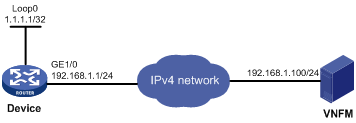
As shown in Figure 1, a VNF is running on the device. The VNFM is installed on a server. The VNF and the VNFM resides on different IP networks.
Configure a Layer 3 connection between the VNF and VNFM.
Procedure
# Assign IP addresses to interfaces and configure routes. Make sure the network connections are available. (Details not shown.)
# On the device, configure a Layer 3 VNF connection to the VNFM.
<Device> system-view
[Device] vnfm 192.168.1.100
# Set the application scenario to VSG and set the relevant parameters.
[Device] vnf cluster-mode vsg cluster-ip 10.2.0.1 tunnel unnumbered interface LoopBack 0
Verifying the configuration
# Display VNF connection information.
<Device> display vnfm information
Slot 0 :Current connect status: ONLINE
Connect mode: L3
VNFM IP: 192.168.1.100
UDP port: 2093
Cluster mode: VSG
Cluster IP: 10.2.0.1
Borrowed interface: LoopBack0
// The output shows that a Layer 3 connection is already established between the VNF and VNFM.
Example: Configuring a VNF connection in Layer 2 mode
Network configuration
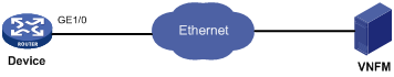
As shown in Figure 2, a VNF is running on the device. The VNFM is installed on a server. The VNF and the VNFM resides in the same broadcast domain.
Configure a Layer 2 connection between the VNF and VNFM.
Procedure
# Connect the device and VNFM to the Ethernet network. Make sure the Ethernet connections are available. (Details not shown.)
# On the device, configure a Layer 2 VNF connection to the VNFM. Specify GigabitEthernet 1/0 as the source interface.
<Device> system-view
[Device] vnfm interface GigabitEthernet 1/0
Verifying the configuration
# Display VNF connection information.
<Device> display vnfm information
Slot 0 :Current connect status: ONLINE
Connect mode: L2
Connect VNFM interface: GigabitEthernet1/0
VNFM MAC: ffff-ffff-ffff
// The output shows that a Layer 2 connection is already established between the VNF and VNFM.