- Table of Contents
-
- 10-High Availability Configuration Examples
- 01-H3C_Ethernet_OAM_Configuration_Examples
- 02-H3C_CFD_Configuration_Examples
- 03-H3C_DLDP_Configuration_Examples
- 04-H3C_RRPP_configuration_examples
- 05-H3C_Smart_Link_Configuration_Examples
- 06-H3C_VRRP_Configuration_Examples
- 07-H3C_BFD_Configuration_Examples
- Related Documents
-
| Title | Size | Download |
|---|---|---|
| 05-H3C_Smart_Link_Configuration_Examples | 246.71 KB |
H3C Smart Link Configuration Examples
Software version: Release 7577P04
Document version: 6W100-20190330
Copyright © 2019 New H3C Technologies Co., Ltd. All rights reserved.
No part of this manual may be reproduced or transmitted in any form or by any means without prior written consent of New H3C Technologies Co., Ltd.
Except for the trademarks of New H3C Technologies Co., Ltd., any trademarks that may be mentioned in this document are the property of their respective owners.
The information in this document is subject to change without notice.
Contents
3 General restrictions and guidelines
4 Example: Configuring Smart Link load sharing
4.3 Restrictions and guidelines
4.4 Verifying the configuration
5 Example: Configuring Smart Link and Monitor Link collaboration
5.3 Restrictions and guidelines
5.5 Verifying the configuration
6 Example: Configuring Smart Link in an IRF fabric
6.3 Restrictions and guidelines
6.4.1 Setting up an IRF fabric
6.4.3 Verifying the configuration
1 Introduction
This document provides Smart Link configuration examples.
2 Prerequisites
This document is not restricted to specific software or hardware versions.
The configuration examples in this document were created and verified in a lab environment, and all the devices were started with the factory default configuration. When you are working on a live network, make sure you understand the potential impact of every command on your network.
This document assumes that you have basic knowledge of Smart Link, Monitor Link, and IRF.
3 General restrictions and guidelines
If you configure a port as both an aggregation group member and a smart link group member, only the aggregation group configuration takes effect. The port is not shown in the output from the display smart-link group command.
4 Example: Configuring Smart Link load sharing
4.1 Network configuration
As shown in 图4-1, VLAN 10 and VLAN 11 are assigned to the Finance department and the Marketing department of an enterprise, respectively. Traffic of VLAN 10 and VLAN 11 on Device A is dually uplinked to Device D by Device B and Device C. Configure Smart Link to meet the following requirements:
· When the link between Device A and Device B and the link between Device A and Device C are both available, the traffic of the Finance department is forwarded trough the link between Device A and Device B. The traffic of the Marketing department is forwarded through the link between Device A and Device C.
· When one link fails, the traffic on the link is switched to another link. When the link recovers, the traffic is switched back to the link.
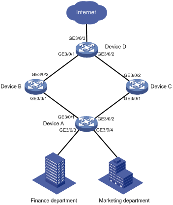
表4-1 Interfaces and IP address assignment
|
Device |
Interface |
VLAN |
Device |
Interface |
VLAN |
|
Device A |
GE3/0/1 |
10, 11 |
Device C |
GE3/0/1 |
10, 11 |
|
GE3/0/2 |
10, 11 |
GE3/0/2 |
10, 11 |
||
|
GE3/0/3 |
10 |
Device D |
GE3/0/1 |
10, 11 |
|
|
GE3/0/4 |
11 |
GE3/0/2 |
10, 11 |
||
|
Device B |
GE3/0/1 |
10, 11 |
GE3/0/3 |
10, 11 |
|
|
GE3/0/2 |
10, 11 |
|
|
4.2 Analysis
To implement load sharing on the two uplinks, create two smart link groups with the same member ports on Device A. The role of each port must be different in the two smart link groups. Use the VLANs of the Finance department and Marketing department as the protected VLANs of the corresponding smart link groups.
For the traffic to switch back to the recovered link, enable role preemption for the two smart link groups.
For the upstream device to refresh MAC address entries and ARP/ND entries when link switchover occurs in a smart link group, perform the following tasks:
· Enable flush message sending on Device A.
· Enable flush message receiving on ports of the primary and secondary links from Device A to Device D.
4.3 Restrictions and guidelines
When you configure Smart Link load sharing, follow these restrictions and guidelines:
· Before you configure a port as a smart link group member, shut down the port to prevent loops. You can bring up the port only after completing the smart link group configuration.
· Disable the spanning tree feature and RRPP on the ports you want to add to a smart link group.
· Make sure the receive control VLAN configured on the upstream device is the same as the transmit control VLAN configured on the smart link device.
· The control VLAN configured for a smart link group must be different from the control VLAN configured for any other smart link groups.
· The control VLAN of a smart link group must also be one of its protected VLANs. Do not remove the control VLAN. Otherwise, flush messages cannot be sent correctly.
4.3.1 Configuring Device A
Create VLAN 10 and VLAN 11.
<DeviceA> system-view
[DeviceA] vlan 10 to 11
Configure GigabitEthernet 3/0/1:
# Configure GigabitEthernet 3/0/1 as a trunk port.
[DeviceA] interface GigabitEthernet 3/0/1
[DeviceA-GigabitEthernet3/0/1] port link-type trunk
# Assign the port to VLAN 10 and VLAN 11.
[DeviceA-GigabitEthernet3/0/1] port trunk permit vlan 10 11
# Remove the port from VLAN 1.
[DeviceA-GigabitEthernet3/0/1] undo port trunk permit vlan 1
# Disable the spanning tree feature on the port.
[DeviceA-GigabitEthernet3/0/1] undo stp enable
# Shut down the port.
[DeviceA-GigabitEthernet3/0/1] shutdown
[DeviceA-GigabitEthernet3/0/1] quit
Configure GigabitEthernet 3/0/2 in the same way GigabitEthernet 3/0/1 is configured.
[DeviceA] interface GigabitEthernet 3/0/2
[DeviceA-GigabitEthernet3/0/2] port link-type trunk
[DeviceA-GigabitEthernet3/0/2] port trunk permit vlan 10 11
[DeviceA-GigabitEthernet3/0/2] undo port trunk permit vlan 1
[DeviceA-GigabitEthernet3/0/2] undo stp enable
[DeviceA-GigabitEthernet3/0/2] shutdown
[DeviceA-GigabitEthernet3/0/2] quit
Configure GigabitEthernet 3/0/3:
# Configure GigabitEthernet 3/0/3 as an access port and assign the port to VLAN 10.
[DeviceA] interface GigabitEthernet 3/0/3
[DeviceA-GigabitEthernet3/0/3] port access vlan 10
# Bring up the port.
[DeviceA-GigabitEthernet3/0/3] undo shutdown
[DeviceA-GigabitEthernet3/0/3] quit
Configure GigabitEthernet 3/0/4:
# Configure GigabitEthernet 3/0/4 as an access port and assign the port to VLAN 11.
[DeviceA] interface GigabitEthernet 3/0/4
[DeviceA-GigabitEthernet3/0/4] port access vlan 11
# Bring up the port.
[DeviceA-GigabitEthernet3/0/4] undo shutdown
[DeviceA-GigabitEthernet3/0/4] quit
Configure the mapping between the VLANs and MSTIs:
# Enter MST region view.
[DeviceA] stp region-configuration
# Map VLAN 10 to MSTI 1, and VLAN 11 to MSTI 2.
[DeviceA-mst-region] instance 1 vlan 10
[DeviceA-mst-region] instance 2 vlan 11
# Activate the MST region configuration.
[DeviceA-mst-region] active region-configuration
[DeviceA-mst-region] quit
Configure smart link group 1:
# Create smart link group 1 and configure the VLAN mapped to MSTI 1, VLAN 10, as the protected VLAN.
[DeviceA] smart-link group 1
[DeviceA-smlk-group1] protected-vlan reference-instance 1
# Configure GigabitEthernet 3/0/1 as the primary port and GigabitEthernet 3/0/2 as the secondary port.
[DeviceA-smlk-group1] port GigabitEthernet 3/0/1 primary
[DeviceA-smlk-group1] port GigabitEthernet 3/0/2 secondary
# Enable flush message sending, and configure VLAN 10 as the transmit control VLAN.
[DeviceA-smlk-group1] flush enable control-vlan 10
# Enable role preemption and set the preemption delay to 10 seconds.
[DeviceA-smlk-group1] preemption mode role
[DeviceA-smlk-group1] preemption delay 10
[DeviceA-smlk-group1] quit
Configure smart link group 2:
# Create smart link group 2 and configure the VLAN mapped to MSTI 2, VLAN 11, as the protected VLAN.
[DeviceA] smart-link group 2
[DeviceA-smlk-group2] protected-vlan reference-instance 2
# Configure GigabitEthernet 3/0/2 as the primary port and GigabitEthernet 3/0/1 as the secondary port.
[DeviceA-smlk-group2] port GigabitEthernet 3/0/2 primary
[DeviceA-smlk-group2] port GigabitEthernet 3/0/1 secondary
# Enable flush message sending, and configure VLAN 11 as the transmit control VLAN.
[DeviceA-smlk-group2] flush enable control-vlan 11
# Enable role preemption and set the preemption delay to 10 seconds.
[DeviceA-smlk-group2] preemption mode role
[DeviceA-smlk-group2] preemption delay 10
[DeviceA-smlk-group2] quit
Bring up the ports:
# Bring up GigabitEthernet 3/0/1.
[DeviceA] interface GigabitEthernet 3/0/1
[DeviceA-GigabitEthernet3/0/1] undo shutdown
[DeviceA-GigabitEthernet3/0/1] quit
# Bring up GigabitEthernet 3/0/2.
[DeviceA] interface GigabitEthernet 3/0/2
[DeviceA-GigabitEthernet3/0/2] undo shutdown
[DeviceA-GigabitEthernet3/0/2] quit
4.3.2 Configuring Device B
Create VLAN 10 and VLAN 11.
<DeviceB> system-view
[DeviceB] vlan 10 to 11
Configure GigabitEthernet 3/0/1:
# Configure GigabitEthernet 3/0/1 as a trunk port.
[DeviceB] interface GigabitEthernet 3/0/1
[DeviceB-GigabitEthernet3/0/1] port link-type trunk
# Assign the port to VLAN 10 and VLAN 11.
[DeviceB-GigabitEthernet3/0/1] port trunk permit vlan 10 11
# Remove the port from VLAN 1.
[DeviceB-GigabitEthernet3/0/1] undo port trunk permit vlan 1
# Enable flush message receiving and configure VLAN 10 and VLAN 11 as the receive control VLANs on the port.
[DeviceB-GigabitEthernet3/0/1] smart-link flush enable control-vlan 10 11
# Bring up the port.
[DeviceB-GigabitEthernet3/0/1] undo shutdown
[DeviceB-GigabitEthernet3/0/1] quit
Configure GigabitEthernet 3/0/2 in the same way GigabitEthernet 3/0/1 is configured.
[DeviceB] interface GigabitEthernet 3/0/2
[DeviceB-GigabitEthernet3/0/2] port link-type trunk
[DeviceB-GigabitEthernet3/0/2] port trunk permit vlan 10 11
[DeviceB-GigabitEthernet3/0/2] undo port trunk permit vlan 1
[DeviceB-GigabitEthernet3/0/2] smart-link flush enable control-vlan 10 11
[DeviceB-GigabitEthernet3/0/2] undo shutdown
[DeviceB-GigabitEthernet3/0/2] quit
4.3.3 Configuring Device C
Create VLAN 10 and VLAN 11.
<DeviceC> system-view
[DeviceC] vlan 10 to 11
Configure GigabitEthernet 3/0/1:
# Configure GigabitEthernet 3/0/1 as a trunk port.
[DeviceC] interface GigabitEthernet 3/0/1
[DeviceC-GigabitEthernet3/0/1] port link-type trunk
# Assign the port to VLAN 10 and VLAN 11.
[DeviceC-GigabitEthernet3/0/1] port trunk permit vlan 10 11
# Remove the port from VLAN 1.
[DeviceC-GigabitEthernet3/0/1] undo port trunk permit vlan 1
# Enable flush message receiving and configure VLAN 10 and VLAN 11 as the receive control VLANs on the port.
[DeviceC-GigabitEthernet3/0/1] smart-link flush enable control-vlan 10 11
# Bring up the port.
[DeviceC-GigabitEthernet3/0/1] undo shutdown
[DeviceC-GigabitEthernet3/0/1] quit
Configure GigabitEthernet 3/0/2 in the same way GigabitEthernet 3/0/1 is configured.
[DeviceC] interface GigabitEthernet 3/0/2
[DeviceC-GigabitEthernet3/0/2] port link-type trunk
[DeviceC-GigabitEthernet3/0/2] port trunk permit vlan 10 11
[DeviceC-GigabitEthernet3/0/2] undo port trunk permit vlan 1
[DeviceC-GigabitEthernet3/0/2] smart-link flush enable control-vlan 10 11
[DeviceC-GigabitEthernet3/0/2] undo shutdown
[DeviceC-GigabitEthernet3/0/2] quit
4.3.4 Configuring Device D
Create VLAN 10 and VLAN 11.
<DeviceD> system-view
[DeviceD] vlan 10 to 11
Configure GigabitEthernet 3/0/1:
# Configure GigabitEthernet 3/0/1 as a trunk port.
[DeviceD] interface GigabitEthernet 3/0/1
[DeviceD-GigabitEthernet3/0/1] port link-type trunk
# Assign the port to VLAN 10 and VLAN 11.
[DeviceD-GigabitEthernet3/0/1] port trunk permit vlan 10 11
# Remove the port from VLAN 1.
[DeviceD-GigabitEthernet3/0/1] undo port trunk permit vlan 1
# Enable flush message receiving and configure VLAN 10 and VLAN 11 as the receive control VLANs on the port.
[DeviceD-GigabitEthernet3/0/1] smart-link flush enable control-vlan 10 11
# Bring up the port.
[DeviceD-GigabitEthernet3/0/1] undo shutdown
[DeviceD-GigabitEthernet3/0/1] quit
Configure GigabitEthernet 3/0/2 in the same way GigabitEthernet 3/0/1 is configured.
[DeviceD] interface GigabitEthernet 3/0/2
[DeviceD-GigabitEthernet3/0/2] port link-type trunk
[DeviceD-GigabitEthernet3/0/2] port trunk permit vlan 10 11
[DeviceD-GigabitEthernet3/0/2] undo port trunk permit vlan 1
[DeviceD-GigabitEthernet3/0/2] smart-link flush enable control-vlan 10 11
[DeviceD-GigabitEthernet3/0/2] undo shutdown
[DeviceD-GigabitEthernet3/0/2] quit
Configure GigabitEthernet 3/0/3:
# Configure GigabitEthernet 3/0/3 as a trunk port
[DeviceD] interface GigabitEthernet 3/0/3
[DeviceD-GigabitEthernet3/0/3] port link-type trunk
# Assign the port to VLAN 10 and VLAN 11.
[DeviceD-GigabitEthernet3/0/3] port trunk permit vlan 10 11
# Remove the port from VLAN 1.
[DeviceD-GigabitEthernet3/0/3] undo port trunk permit vlan 1
# Bring up the port.
[DeviceD-GigabitEthernet3/0/3] undo shutdown
[DeviceD-GigabitEthernet3/0/3] quit
4.4 Verifying the configuration
Verify the Smart Link configuration when Device A is operating correctly:
# Display information about all smart link groups on Device A.
[DeviceA] display smart-link group all
Smart link group 1 information:
Device ID : 0000-fc00-2500
Preemption mode : ROLE
Preemption delay: 10(s)
Control VLAN : 10
Protected VLAN : Reference Instance 1
Member Role State Flush-count Last-flush-time
-----------------------------------------------------------------------------
GE3/0/1 PRIMARY ACTIVE 0 NA
GE3/0/2 SECONDARY STANDBY 2 16:22:40 2014/12/29
Smart link group 2 information:
Device ID : 0000-fc00-2500
Preemption mode : ROLE
Preemption delay: 10(s)
Control VLAN : 11
Protected VLAN : Reference Instance 2
Member Role State Flush-count Last-flush-time
-----------------------------------------------------------------------------
GE3/0/2 PRIMARY ACTIVE 2 16:22:40 2014/12/29
GE3/0/1 SECONDARY STANDBY 0 NA
The output shows the following information:
¡ In smart link group 1, GigabitEthernet 3/0/1 is active to transmit traffic for MSTI 1.
¡ In smart link group 2, GigabitEthernet 3/0/2 is active to transmit traffic for MSTI 2.
Verify the Smart Link configuration when GigabitEthernet 3/0/1 on Device A is down:
# Display information about all smart link groups on Device A.
[DeviceA] display smart-link group all
Smart link group 1 information:
Device ID : 0000-fc00-2500
Preemption mode : ROLE
Preemption delay: 10(s)
Control VLAN : 10
Protected VLAN : Reference Instance 1
Member Role State Flush-count Last-flush-time
-----------------------------------------------------------------------------
GE3/0/1 PRIMARY DOWN 0 NA
GE3/0/2 SECONDARY ACTIVE 3 17:43:06 2014/12/29
Smart link group 2 information:
Device ID : 0000-fc00-2500
Preemption mode : ROLE
Preemption delay: 10(s)
Control VLAN : 11
Protected VLAN : Reference Instance 2
Member Role State Flush-count Last-flush-time
-----------------------------------------------------------------------------
GE3/0/2 PRIMARY ACTIVE 2 16:22:40 2014/12/29
GE3/0/1 SECONDARY DOWN 0 NA
The output shows the following information:
¡ In smart link group 1, GigabitEthernet 3/0/2 becomes active to transmit traffic for MSTI 1.
¡ In smart link group 2, GigabitEthernet 3/0/2 remains active to transmit traffic for MSTI 2.
# Display information about the received flush messages on Device B.
[DeviceB] display smart-link flush
Received flush packets : 1
Receiving interface of the last flush packet : GigabitEthernet3/0/2
Receiving time of the last flush packet : 07:57:22 2014/10/23
Device ID of the last flush packet : 0000-fc00-2500
Control VLAN of the last flush packet : 10
4.5 Configuration files
· Device A:
#
vlan 1
#
vlan 10 to 11
#
stp region-configuration
instance 1 vlan 10
instance 2 vlan 11
active region-configuration
#
smart-link group 1
preemption mode role
preemption delay 10
flush enable control-vlan 10
protected-vlan reference-instance 1
smart-link group 2
preemption mode role
preemption delay 10
flush enable control-vlan 11
protected-vlan reference-instance 2
#
interface GigabitEthernet3/0/1
port link-mode bridge
port link-type trunk
undo port trunk permit vlan 1
port trunk permit vlan 10 to 11
undo stp enable
port smart-link group 1 primary
port smart-link group 2 secondary
#
interface GigabitEthernet3/0/2
port link-mode bridge
port link-type trunk
undo port trunk permit vlan 1
port trunk permit vlan 10 to 11
undo stp enable
port smart-link group 1 secondary
port smart-link group 2 primary
#
· Device B:
#
vlan 1
#
vlan 10 to 11
#
monitor-link group 1
#
interface GigabitEthernet3/0/1
port link-mode bridge
port link-type trunk
undo port trunk permit vlan 1
port trunk permit vlan 10 to 11
smart-link flush enable control-vlan 10 to 11
port monitor-link group 1 downlink
#
interface GigabitEthernet3/0/2
port link-mode bridge
port link-type trunk
undo port trunk permit vlan 1
port trunk permit vlan 10 to 11
smart-link flush enable control-vlan 10 to 11
port monitor-link group 1 uplink
#
· Device C:
#
vlan 1
#
vlan 10 to 11
#
monitor-link group 1
#
interface GigabitEthernet3/0/1
port link-mode bridge
port link-type trunk
undo port trunk permit vlan 1
port trunk permit vlan 10 to 11
smart-link flush enable control-vlan 10 to 11
port monitor-link group 1 downlink
#
interface GigabitEthernet3/0/2
port link-mode bridge
port link-type trunk
undo port trunk permit vlan 1
port trunk permit vlan 10 to 11
smart-link flush enable control-vlan 10 to 11
port monitor-link group 1 uplink
#
· Device D:
#
vlan 1
#
vlan 10 to 11
#
interface GigabitEthernet3/0/1
port link-mode bridge
port link-type trunk
undo port trunk permit vlan 1
port trunk permit vlan 10 to 11
smart-link flush enable control-vlan 10 to 11
#
interface GigabitEthernet3/0/2
port link-mode bridge
port link-type trunk
undo port trunk permit vlan 1
port trunk permit vlan 10 to 11
smart-link flush enable control-vlan 10 to 11
#
interface GigabitEthernet3/0/3
port link-mode bridge
port link-type trunk
undo port trunk permit vlan 1
port trunk permit vlan 10 to 11
#
5 Example: Configuring Smart Link and Monitor Link collaboration
5.1 Network configuration
As shown in 图5-1, VLAN 10 and VLAN 11 are assigned to Zone A and Zone B, respectively. Traffic of VLAN 10 on Device A and traffic of VLAN 11 on Device B are dually uplinked to Device E by Device C and Device D. Configure Smart Link and Monitor Link to meet the following requirements:
· When the link between Device A and Device C and the link between Device A and Device D are both available, the traffic of Zone A is forwarded trough the link between Device A and Device C. When the link between Device A and Device C fails, the traffic is switched to the link between Device A and Device D. When the link between Device A and Device C recovers, the traffic switches back to the link.
· When the link between Device B and Device C and the link between Device B and Device D are both available, the traffic of Zone B is forwarded trough the link between Device B and Device D. When the link between Device B and Device D fails, the traffic is switched to the link between Device B and Device C. When the link between Device B and Device D recovers, the traffic switches back to the link.
· Configure Monitor Link on Device C and Device D to associate the state of downlink interfaces on Device C and Device D with the state of uplink interfaces. When Monitor link shuts down the downlink interfaces because of an uplink failure, Smart Link triggers a link switchover.
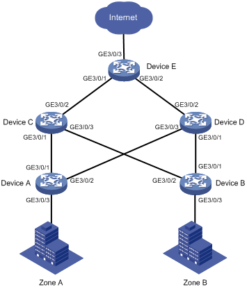
表5-1 Interfaces and IP address assignment
|
Device |
Interface |
VLAN |
Device |
Interface |
VLAN |
|
Device A |
GE3/0/1 |
10 |
Device D |
GE3/0/1 |
11 |
|
GE3/0/2 |
10 |
GE3/0/2 |
10, 11 |
||
|
GE3/0/3 |
10 |
GE3/0/3 |
10 |
||
|
Device B |
GE3/0/1 |
11 |
Device E |
GE3/0/1 |
10, 11 |
|
GE3/0/2 |
11 |
GE3/0/2 |
10, 11 |
||
|
GE3/0/3 |
11 |
GE3/0/3 |
10, 11 |
||
|
Device C |
GE3/0/1 |
10 |
|
|
|
|
GE3/0/2 |
10, 11 |
|
|
|
|
|
GE3/0/3 |
11 |
|
|
|
5.2 Analysis
To implement dual uplink backup on Device A and Device B, perform the following tasks:
· Create a smart link group on Device A and Device B, respectively.
· Configure the VLANs of Zone A and Zone B as the protected VLANs of the corresponding smart link groups.
For the traffic to switch back to the recovered link, enable role preemption for the two smart link groups.
For the upstream device to refresh MAC address forwarding entries and ARP/ND entries when link switchover occurs in a smart link group, perform the following tasks:
· Enable flush message sending on Device A and Device B.
· Enable flush message receiving on the downlink ports on Device C and Device D.
5.3 Restrictions and guidelines
When you configure Smart Link and Monitor Link collaboration, follow these restrictions and guidelines:
· Before you configure a port as a smart link group member, shut down the port to prevent loops. You can bring up the port only after completing the smart link group configuration.
· Disable the spanning tree feature and RRPP on the ports you want to add to the smart link group.
· Make sure the receive control VLAN configured on the upstream device is the same as the transmit control VLAN configured on the smart link device.
· The control VLAN configured for a smart link group must be different from the control VLAN configured for any other smart link groups.
· The control VLAN of a smart link group must also be one of its protected VLANs. Do not remove the control VLAN. Otherwise, flush messages cannot be sent correctly.
· You can assign a port to only one monitor link group.
· Do not use the shutdown command or the undo shutdown command to change the state of the downlink interfaces in a monitor link group.
5.4 Procedures
5.4.1 Configuring Device A
Create VLAN 10 and VLAN 11.
<DeviceA> system-view
[DeviceA] vlan 10 to 11
Configure GigabitEthernet 3/0/1:
# Configure GigabitEthernet 3/0/1 as a trunk port.
[DeviceA] interface GigabitEthernet 3/0/1
[DeviceA-GigabitEthernet3/0/1] port link-type trunk
# Assign the port to VLAN 10.
[DeviceA-GigabitEthernet3/0/1] port trunk permit vlan 10
# Remove the port from VLAN 1.
[DeviceA-GigabitEthernet3/0/1] undo port trunk permit vlan 1
# Disable the spanning tree feature on the port.
[DeviceA-GigabitEthernet3/0/1] undo stp enable
# Shut down the port.
[DeviceA-GigabitEthernet3/0/1] shutdown
[DeviceA-GigabitEthernet3/0/1] quit
Configure GigabitEthernet 3/0/2 in the same way GigabitEthernet 3/0/1 is configured.
[DeviceA] interface GigabitEthernet 3/0/2
[DeviceA-GigabitEthernet3/0/2] port link-type trunk
[DeviceA-GigabitEthernet3/0/2] port trunk permit vlan 10 11
[DeviceA-GigabitEthernet3/0/2] undo port trunk permit vlan 1
[DeviceA-GigabitEthernet3/0/2] undo stp enable
[DeviceA-GigabitEthernet3/0/2] shutdown
[DeviceA-GigabitEthernet3/0/2] quit
Configure GigabitEthernet 3/0/3:
# Configure GigabitEthernet 3/0/3 as an access port and assign the port to VLAN 10.
[DeviceA] interface GigabitEthernet 3/0/3
[DeviceA-GigabitEthernet3/0/3] port access vlan 10
# Bring up the port.
[DeviceA-GigabitEthernet3/0/3] undo shutdown
[DeviceA-GigabitEthernet3/0/3] quit
Configure the mapping between VLAN 10 and an MSTI:
# Enter MST region view.
[DeviceA] stp region-configuration
# Map VLAN 10 to MSTI 1.
[DeviceA-mst-region] instance 1 vlan 10
# Activate the MST region configuration.
[DeviceA-mst-region] active region-configuration
[DeviceA-mst-region] quit
Configure smart link group 1.
# Create smart link group 1 and configure the VLAN mapped to MSTI 1, VLAN 10, as the protected VLAN.
[DeviceA] smart-link group 1
[DeviceA-smlk-group1] protected-vlan reference-instance 1
# Configure GigabitEthernet 3/0/1 as the primary port and GigabitEthernet 3/0/2 as the secondary port.
[DeviceA-smlk-group1] port GigabitEthernet 3/0/1 primary
[DeviceA-smlk-group1] port GigabitEthernet 3/0/2 secondary
# Enable flush message sending, and configure VLAN 10 as the transmit control VLAN.
[DeviceA-smlk-group1] flush enable control-vlan 10
# Enable role preemption and set the preemption delay to 10 seconds.
[DeviceA-smlk-group1] preemption mode role
[DeviceA-smlk-group1] preemption delay 10
[DeviceA-smlk-group1] quit
Bring up the ports:
# Bring up GigabitEthernet 3/0/1.
[DeviceA] interface GigabitEthernet 3/0/1
[DeviceA-GigabitEthernet3/0/1] undo shutdown
[DeviceA-GigabitEthernet3/0/1] quit
# Bring up GigabitEthernet 3/0/2.
[DeviceA] interface GigabitEthernet 3/0/2
[DeviceA-GigabitEthernet3/0/2] undo shutdown
[DeviceA-GigabitEthernet3/0/2] quit
5.4.2 Configuring Device B
Create VLAN 10 and VLAN 11.
<DeviceB> system-view
[DeviceB] vlan 10 to 11
Configure GigabitEthernet 3/0/1:
# Configure GigabitEthernet 3/0/1 as a trunk port.
[DeviceB] interface GigabitEthernet 3/0/1
[DeviceB-GigabitEthernet3/0/1] port link-type trunk
# Assign the port to VLAN 11.
[DeviceB-GigabitEthernet3/0/1] port trunk permit vlan 11
# Remove the port from VLAN 1.
[DeviceB-GigabitEthernet3/0/1] undo port trunk permit vlan 1
# Disable the spanning tree feature on the port.
[DeviceB-GigabitEthernet3/0/1] undo stp enable
# Shut down the port.
[DeviceB-GigabitEthernet3/0/1] shutdown
[DeviceB-GigabitEthernet3/0/1] quit
Configure GigabitEthernet 3/0/2 in the same way GigabitEthernet 3/0/1 is configured.
[DeviceB] interface GigabitEthernet 3/0/2
[DeviceB-GigabitEthernet3/0/2] port link-type trunk
[DeviceB-GigabitEthernet3/0/2] port trunk permit vlan 11
[DeviceB-GigabitEthernet3/0/2] undo port trunk permit vlan 1
[DeviceB-GigabitEthernet3/0/2] undo stp enable
[DeviceB-GigabitEthernet3/0/2] shutdown
[DeviceB-GigabitEthernet3/0/2] quit
Configure GigabitEthernet 3/0/3:
# Configure GigabitEthernet 3/0/3 as an access port and assign the port to VLAN 11.
[DeviceB] interface GigabitEthernet 3/0/3
[DeviceB-GigabitEthernet3/0/3] port access vlan 11
# Bring up the port.
[DeviceB-GigabitEthernet3/0/3] undo shutdown
[DeviceB-GigabitEthernet3/0/3] quit
Configure the mapping between VLAN 11 and an MSTI:
# Enter MST region view.
[DeviceB] stp region-configuration
# Map VLAN 11 to MSTI 1.
[DeviceB-mst-region] instance 1 vlan 11
# Activate the MST region configuration
[DeviceB-mst-region] active region-configuration
[DeviceB-mst-region] quit
Configure smart link group 1.
# Create smart link group 1 and configure the VLAN mapped to MSTI 1, VLAN 11, as the protected VLAN.
[DeviceB] smart-link group 1
[DeviceB-smlk-group1] protected-vlan reference-instance 1
# Configure GigabitEthernet 3/0/1 as the primary port and GigabitEthernet 3/0/2 as the secondary port.
[DeviceB-smlk-group1] port GigabitEthernet 3/0/1 primary
[DeviceB-smlk-group1] port GigabitEthernet 3/0/2 secondary
# Enable flush message sending, and configure VLAN 11 as the transmit control VLAN.
[DeviceA-smlk-group1] flush enable control-vlan 11
# Enable role preemption and set the preemption delay to 10 seconds.
[DeviceB-smlk-group1] preemption mode role
[DeviceB-smlk-group1] preemption delay 10
[DeviceB-smlk-group1] quit
Bring up the ports:
# Bring up GigabitEthernet 3/0/1.
[DeviceB] interface GigabitEthernet 3/0/1
[DeviceB-GigabitEthernet3/0/1] undo shutdown
[DeviceB-GigabitEthernet3/0/1] quit
# Bring up GigabitEthernet 3/0/2.
[DeviceB] interface GigabitEthernet 3/0/2
[DeviceB-GigabitEthernet3/0/2] undo shutdown
[DeviceB-GigabitEthernet3/0/2] quit
5.4.3 Configuring Device C
Create VLAN 10 and VLAN 11.
<DeviceC> system-view
[DeviceC] vlan 10 to 11
Configure GigabitEthernet 3/0/1:
# Configure GigabitEthernet 3/0/1 as a trunk port.
[DeviceC] interface GigabitEthernet 3/0/1
[DeviceC-GigabitEthernet3/0/1] port link-type trunk
# Assign the port to VLAN 10.
[DeviceC-GigabitEthernet3/0/1] port trunk permit vlan 10
# Remove the port from VLAN 1.
[DeviceC-GigabitEthernet3/0/1] undo port trunk permit vlan 1
# Enable flush message receiving and configure VLAN 10 as the receive control VLAN on the port.
[DeviceC-GigabitEthernet3/0/1] smart-link flush enable control-vlan 10
# Bring up the port.
[DeviceC-GigabitEthernet3/0/1] undo shutdown
[DeviceC-GigabitEthernet3/0/1] quit
Configure GigabitEthernet 3/0/2:
# Configure GigabitEthernet 3/0/2 as a trunk port.
[DeviceC] interface GigabitEthernet 3/0/2
[DeviceC-GigabitEthernet3/0/2] port link-type trunk
# Assign the port to VLAN 10 and VLAN 11.
[DeviceC-GigabitEthernet3/0/2] port trunk permit vlan 10 11
# Remove the port from VLAN 1.
[DeviceC-GigabitEthernet3/0/2] undo port trunk permit vlan 1
# Enable flush message receiving and configure VLAN 10 and VLAN 11 as the receive control VLANs on the port.
[DeviceC-GigabitEthernet3/0/2] smart-link flush enable control-vlan 10 11
# Bring up the port.
[DeviceC-GigabitEthernet3/0/2] undo shutdown
[DeviceC-GigabitEthernet3/0/2] quit
Configure GigabitEthernet 3/0/3:
# Configure GigabitEthernet 3/0/3 as a trunk port.
[DeviceC] interface GigabitEthernet 3/0/3
[DeviceC-GigabitEthernet3/0/3] port link-type trunk
# Assign the port to VLAN 11.
[DeviceC-GigabitEthernet3/0/3] port trunk permit vlan 11
# Remove the port from VLAN 1.
[DeviceC-GigabitEthernet3/0/3] undo port trunk permit vlan 1
# Enable flush message receiving and configure VLAN 11 as the receive control VLAN on the port.
[DeviceC-GigabitEthernet3/0/3] smart-link flush enable control-vlan 11
# Bring up the port.
[DeviceB-GigabitEthernet3/0/3] undo shutdown
[DeviceB-GigabitEthernet3/0/3] quit
Configure monitor link group 1:
# Create monitor link group 1.
[DeviceC] monitor-link group 1
# Configure GigabitEthernet 3/0/2 as the uplink port and GigabitEthernet 3/0/1 and GigabitEthernet 3/0/3 as the downlink ports.
[DeviceC-mtlk-group1] port GigabitEthernet 3/0/2 uplink
[DeviceC-mtlk-group1] port GigabitEthernet 3/0/1 downlink
[DeviceC-mtlk-group1] port GigabitEthernet 3/0/3 downlink
[DeviceC-mtlk-group1] quit
5.4.4 Configuring Device D
Create VLAN 10 and VLAN 11.
<DeviceD> system-view
[DeviceD] vlan 10 to 11
Configure GigabitEthernet 3/0/1:
# Configure GigabitEthernet 3/0/1 as a trunk port.
[DeviceD] interface GigabitEthernet 3/0/1
[DeviceD-GigabitEthernet3/0/1] port link-type trunk
# Assign the port to VLAN 11.
[DeviceD-GigabitEthernet3/0/1] port trunk permit vlan 11
# Remove the port from VLAN 1.
[DeviceD-GigabitEthernet3/0/1] undo port trunk permit vlan 1
# Enable flush message receiving and configure VLAN 11 as the receive control VLAN on the port.
[DeviceD-GigabitEthernet3/0/1] smart-link flush enable control-vlan 11
# Bring up the port.
[DeviceD-GigabitEthernet3/0/1] undo shutdown
[DeviceD-GigabitEthernet3/0/1] quit
Configure GigabitEthernet 3/0/2:
# Configure GigabitEthernet 3/0/2 as a trunk port.
[DeviceD] interface GigabitEthernet 3/0/2
[DeviceD-GigabitEthernet3/0/2] port link-type trunk
# Assign the port to VLAN 10 and VLAN 11.
[DeviceD-GigabitEthernet3/0/2] port trunk permit vlan 10 11
# Remove the port from VLAN 1.
[DeviceD-GigabitEthernet3/0/2] undo port trunk permit vlan 1
# Enable flush message receiving and configure VLAN 10 and VLAN 11 as the receive control VLANs on the port.
[DeviceD-GigabitEthernet3/0/2] smart-link flush enable control-vlan 10 11
# Bring up the port.
[DeviceD-GigabitEthernet3/0/2] undo shutdown
[DeviceD-GigabitEthernet3/0/2] quit
Configure GigabitEthernet 3/0/3:
# Configure GigabitEthernet 3/0/3 as a trunk port.
[DeviceD] interface GigabitEthernet 3/0/3
[DeviceD-GigabitEthernet3/0/3] port link-type trunk
# Assign the port to VLAN 10.
[DeviceD-GigabitEthernet3/0/3] port trunk permit vlan 10
# Remove the port from VLAN 1.
[DeviceD-GigabitEthernet3/0/3] undo port trunk permit vlan 1
# Enable flush message receiving and configure VLAN 10 as the receive control VLAN on the port.
[DeviceD-GigabitEthernet3/0/3] smart-link flush enable control-vlan 10
# Bring up the port.
[DeviceD-GigabitEthernet3/0/3] undo shutdown
[DeviceD-GigabitEthernet3/0/3] quit
Configure monitor link group 1:
# Create monitor link group 1.
[DeviceD] monitor-link group 1
# Configure GigabitEthernet 3/0/2 as the uplink port and GigabitEthernet 3/0/1 and GigabitEthernet 3/0/3 as the downlink ports.
[DeviceD-mtlk-group1] port GigabitEthernet 3/0/2 uplink
[DeviceD-mtlk-group1] port GigabitEthernet 3/0/1 downlink
[DeviceD-mtlk-group1] port GigabitEthernet 3/0/3 downlink
[DeviceD-mtlk-group1] quit
5.4.5 Configuring Device E
Create VLAN 10 and VLAN 11.
<DeviceE> system-view
[DeviceE] vlan 10 to 11
Configure GigabitEthernet 3/0/1:
# Configure GigabitEthernet 3/0/1 as a trunk port.
[DeviceE] interface GigabitEthernet 3/0/1
[DeviceE-GigabitEthernet3/0/1] port link-type trunk
# Assign the port to VLAN 10 and VLAN 11.
[DeviceE-GigabitEthernet3/0/1] port trunk permit vlan 10 11
# Remove the port from VLAN 1.
[DeviceE-GigabitEthernet3/0/1] undo port trunk permit vlan 1
# Enable flush message receiving and configure VLAN 10 and VLAN 11 as the receive control VLANs on the port.
[DeviceE-GigabitEthernet3/0/1] smart-link flush enable control-vlan 10 11
# Bring up the port.
[DeviceE-GigabitEthernet3/0/1] undo shutdown
[DeviceE-GigabitEthernet3/0/1] quit
Configure GigabitEthernet 3/0/2 in the same way GigabitEthernet 3/0/1 is configured.
[DeviceE] interface GigabitEthernet 3/0/2
[DeviceE-GigabitEthernet3/0/2] port link-type trunk
[DeviceE-GigabitEthernet3/0/2] port trunk permit vlan 10 11
[DeviceE-GigabitEthernet3/0/2] undo port trunk permit vlan 1
[DeviceE-GigabitEthernet3/0/2] smart-link flush enable control-vlan 10 11
[DeviceE-GigabitEthernet3/0/2] undo shutdown
[DeviceE-GigabitEthernet3/0/2] quit
Configure GigabitEthernet 3/0/3:
# Configure GigabitEthernet 3/0/3 as a trunk port.
[DeviceE] interface GigabitEthernet 3/0/3
[DeviceE-GigabitEthernet3/0/3] port link-type trunk
# Assign the port to VLAN 10 and VLAN 11.
[DeviceE-GigabitEthernet3/0/3] port trunk permit vlan 10 11
# Remove the port from VLAN 1.
[DeviceE-GigabitEthernet3/0/3] undo port trunk permit vlan 1
# Bring up the port.
[DeviceE-GigabitEthernet3/0/3] undo shutdown
[DeviceE-GigabitEthernet3/0/3] quit
5.5 Verifying the configuration
Verify the configuration when Device A and Device B are operating correctly:
# Display information about all smart link groups on Device A.
[DeviceA] display smart-link group all
Smart link group 1 information:
Device ID : 0000-fc00-2500
Preemption mode : ROLE
Preemption delay: 10(s)
Control VLAN : 10
Protected VLAN : Reference Instance 1
Member Role State Flush-count Last-flush-time
-----------------------------------------------------------------------------
GE3/0/1 PRIMARY ACTIVE 1 19:37:49 2014/12/29
GE3/0/2 SECONDARY STANDBY 3 17:43:06 2014/12/29
The output shows that GigabitEthernet 3/0/1 in smart link group 1 is active to transmit traffic for MSTI 1.
# Display information about all smart link groups on Device B.
[DeviceB] display smart-link group all
Smart link group 1 information:
Device ID : 0000-fc00-2500
Preemption mode : ROLE
Preemption delay: 10(s)
Control VLAN : 11
Protected VLAN : Reference Instance 2
Member Role State Flush-count Last-flush-time
-----------------------------------------------------------------------------
GE3/0/1 PRIMARY ACTIVE 2 16:22:40 2014/12/29
GE3/0/2 SECONDARY STANDBY 0 NA
The output shows that GigabitEthernet 3/0/1 in smart link group 1 is active to transmit traffic for MSTI 2.
Verify the configuration when Device C and Device D are operating correctly:
# Display information about all monitor link groups on Device C.
[DeviceC] display monitor-link group all
Monitor link group 1 information:
Group status : UP
Downlink up-delay: 0(s)
Last-up-time : 10:07:26 2014/10/23
Last-down-time : -
Member Role Status
--------------------------------------------
GE3/0/2 UPLINK UP
GE3/0/1 DOWNLINK UP
GE3/0/3 DOWNLINK UP
The output shows when the uplink port GigabitEthernet 3/0/2 is up, the status of monitor link group 1 is up.
# Display information about all monitor link groups on Device D.
[DeviceD] display monitor-link group all
Monitor link group 1 information:
Group status : UP
Downlink up-delay: 0(s)
Last-up-time : 19:49:33 2014/12/29
Last-down-time : -
Member Role Status
--------------------------------------------
GE3/0/2 UPLINK UP
GE3/0/1 DOWNLINK UP
GE3/0/3 DOWNLINK UP
The output shows when the uplink port GigabitEthernet 3/0/2 is up, the status of monitor link group 1 is up.
Verify the configuration when GigabitEthernet 3/0/1 on Device A or Device B is down:
# Display information about all smart link groups on Device A.
[DeviceA] display smart-link group all
Smart link group 1 information:
Device ID : 0000-fc00-2500
Preemption mode : ROLE
Preemption delay: 10(s)
Control VLAN : 10
Protected VLAN : Reference Instance 1
Member Role State Flush-count Last-flush-time
-----------------------------------------------------------------------------
GE3/0/1 PRIMARY DOWN 1 NA
GE3/0/2 SECONDAR ACTIVE 3 17:43:06 2014/12/29
The output shows that GigabitEthernet 3/0/2 in smart link group 1 becomes active to transmit traffic for MSTI 1.
# Display information about all smart link groups on Device B.
[DeviceB] display smart-link group all
Smart link group 1 information:
Device ID : 0000-fc00-2500
Preemption mode : ROLE
Preemption delay: 10(s)
Control VLAN : 11
Protected VLAN : Reference Instance 2
Member Role State Flush-count Last-flush-time
-----------------------------------------------------------------------------
GE3/0/1 PRIMARY DOWN 1 NA
GE3/0/2 SECONDAR ACTIVE 3 17:43:06 2014/12/29
The output shows that GigabitEthernet 3/0/2 in smart link group 1 becomes active to transmit traffic for MSTI 2.
# Display information about the received flush messages on Device C.
[DeviceC] display smart-link flush
Received flush packets : 1
Receiving interface of the last flush packet : GigabitEthernet3/0/1
Receiving time of the last flush packet : 07:57:22 2014/10/23
Device ID of the last flush packet : 0000-fc00-2500
Control VLAN of the last flush packet : 10
# Display information about the received flush messages on Device D.
[DeviceD] display smart-link flush
Received flush packets : 1
Receiving interface of the last flush packet : GigabitEthernet3/0/1
Receiving time of the last flush packet : 07:57:22 2014/10/23
Device ID of the last flush packet : 0000-fc00-2500
Control VLAN of the last flush packet : 11
Verify the configuration when the uplink ports on Device C or Device D fail:
# Display information about all monitor link groups on Device C.
[DeviceC] display monitor-link group all
Monitor link group 1 information:
Group status : DOWN
Downlink up-delay: 0(s)
Last-up-time : 10:07:26 2014/10/23
Last-down-time : -
Member Role Status
--------------------------------------------
GE3/0/2 UPLINK DOWN
GE3/0/1 DOWNLINK DOWN
GE3/0/3 DOWNLINK DOWN
The output shows that when the uplink port GigabitEthernet 3/0/2 is down, the status of monitor link group 1 is down.
# Display information about all monitor link groups on Device D.
DeviceD] display monitor-link group all
Monitor link group 1 information:
Group status : DOWN
Downlink up-delay: 0(s)
Last-up-time : 19:49:33 2014/12/29
Last-down-time : -
Member Role Status
--------------------------------------------
GE3/0/2 UPLINK DOWN
GE3/0/1 DOWNLINK DOWN
GE3/0/3 DOWNLINK DOWN
The output shows that when the uplink port GigabitEthernet 3/0/2 is down, the status of monitor link group 1 is down.
5.6 Configuration files
· Device A:
#
vlan 1
#
vlan 10
#
stp region-configuration
instance 1 vlan 10
active region-configuration
#
smart-link group 1
preemption mode role
flush enable control-vlan 10
protected-vlan reference-instance 1
#
interface GigabitEthernet3/0/1
port link-mode bridge
port link-type trunk
undo port trunk permit vlan 1
port trunk permit vlan 10
undo stp enable
port smart-link group 1 primary
#
interface GigabitEthernet3/0/2
port link-mode bridge
port link-type trunk
undo port trunk permit vlan 1
port trunk permit vlan 10
undo stp enable
port smart-link group 1 secondary
#
interface GigabitEthernet3/0/3
port link-mode bridge
port access vlan 10
#
· Device B:
#
vlan 1
#
vlan 11
#
stp region-configuration
instance 1 vlan 11
active region-configuration
#
smart-link group 1
preemption mode role
flush enable control-vlan 11
protected-vlan reference-instance 1
#
interface GigabitEthernet3/0/1
port link-mode bridge
port link-type trunk
undo port trunk permit vlan 1
port trunk permit vlan 11
undo stp enable
port smart-link group 1 primary
#
interface GigabitEthernet3/0/2
port link-mode bridge
port link-type trunk
undo port trunk permit vlan 1
port trunk permit vlan 11
undo stp enable
port smart-link group 1 secondary
#
interface GigabitEthernet3/0/3
port link-mode bridge
port access vlan 11
#
· Device C:
#
vlan 1
#
vlan 10 to 11
#
monitor-link group 1
monitor-link group 2
#
interface GigabitEthernet3/0/1
port link-mode bridge
port link-type trunk
undo port trunk permit vlan 1
port trunk permit vlan 10
smart-link flush enable control-vlan 10
port monitor-link group 1 downlink
#
interface GigabitEthernet3/0/2
port link-mode bridge
port link-type trunk
undo port trunk permit vlan 1
port trunk permit vlan 10 to 11
smart-link flush enable control-vlan 10 to 11
port monitor-link group 1 uplink
#
interface GigabitEthernet3/0/3
port link-mode bridge
port link-type trunk
undo port trunk permit vlan 1
port trunk permit vlan 11
smart-link flush enable control-vlan 11
port monitor-link group 1 downlink
#
· Device D:
#
vlan 1
#
vlan 10 to 11
#
monitor-link group 1
monitor-link group 2
#
interface GigabitEthernet3/0/1
port link-mode bridge
port link-type trunk
undo port trunk permit vlan 1
port trunk permit vlan 11
smart-link flush enable control-vlan 11
port monitor-link group 1 downlink
#
interface GigabitEthernet3/0/2
port link-mode bridge
port link-type trunk
undo port trunk permit vlan 1
port trunk permit vlan 10 to 11
smart-link flush enable control-vlan 10 to 11
port monitor-link group 1 uplink
#
interface GigabitEthernet3/0/3
port link-mode bridge
port link-type trunk
undo port trunk permit vlan 1
port trunk permit vlan 10
smart-link flush enable control-vlan 10
port monitor-link group 1 downlink
#
· Device E:
#
vlan 1
#
vlan 10 to 11
#
interface GigabitEthernet3/0/1
port link-mode bridge
port link-type trunk
undo port trunk permit vlan 1
port trunk permit vlan 10 to 11
smart-link flush enable control-vlan 10 to 11
#
interface GigabitEthernet3/0/2
port link-mode bridge
port link-type trunk
undo port trunk permit vlan 1
port trunk permit vlan 10 to 11
smart-link flush enable control-vlan 10 to 11
#
interface GigabitEthernet3/0/3
port link-mode bridge
port link-type trunk
undo port trunk permit vlan 1
port trunk permit vlan 10 to 11
#
6 Example: Configuring Smart Link in an IRF fabric
6.1 Network configuration
As shown in 图6-1, the Finance department in VLAN 10 and the Marketing department in VLAN 11 are connected to Device A and Device B, respectively. Device A and Device B form an IRF fabric and are connected to Device C and Device D.
Configure Smart Link to meet the following requirements:
· When the uplinks of Device A and Device B are available, traffic is forward through the link between Device A and Device C.
· When the link between Device A and Device C fails, the traffic switches to another link.
· When the link recovers, the traffic is switched back to the link.
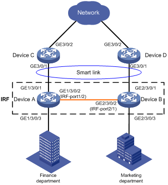
表6-1 Interfaces and IP address assignment
|
Device |
Interface |
VLAN |
Device |
Interface |
Device |
|
Device A |
GE1/3/0/1 |
10, 11 |
Device B |
GE2/3/0/1 |
10, 11 |
|
GE1/3/0/3 |
10 |
GE2/3/0/3 |
11 |
||
|
Device C |
GE3/0/1 |
10, 11 |
Device D |
GE3/0/1 |
10, 11 |
|
GE3/0/2 |
10, 11 |
GE3/0/2 |
10, 11 |
6.2 Analysis
To implement dual uplink redundancy on Device A and Device B, configure a smart link group for the IRF fabric formed by Device A and Device B.
For the traffic to switch back to the recovered link, enable role preemption for the two smart link groups.
For the upstream device to refresh MAC address forwarding entries and ARP/ND entries when link switchover occurs in a smart link group, perform the following tasks:
· Enable flush message sending on Device A and Device B.
· Enable flush message receiving on GigabitEthernet 3/0/1 on Device C and Device D.
6.3 Restrictions and guidelines
When you configure Smart Link in an IRF fabric, follow these restrictions and guidelines:
· Before you configure a port as a smart link group member, shut down the port to prevent loops. You can bring up the port only after completing the smart link group configuration.
· Disable the spanning tree feature and RRPP on the ports you want to add to the smart link group.
· Make sure the receive control VLAN configured on the upstream device is the same as the transmit control VLAN configured on the smart link device.
· The control VLAN of a smart link group must also be one of its protected VLANs. Do not remove the control VLAN. Otherwise, flush messages cannot be sent correctly.
· For the restrictions and guidelines for configuring IRF, see H3C S10500 Routing Switch Series Virtual Technologies Configuration Guide.
6.4 Procedures
6.4.1 Setting up an IRF fabric
1. Configuring Device A
# Assign IRF member ID 1 to Device A, and bind GigabitEthernet3/0/2 to IRF port 2.
<DeviceA> system-view
[DeviceA] irf member 1 renumber 1
[DeviceA] irf-port 2
[DeviceA-irf-port2] port group interface gigabitEthernet 3/0/2
[DeviceA-irf-port2] quit
# Save the configuration.
[DeviceA] save
# Enable IRF mode.
[DeviceA] chassis convert mode irf
The device will switch to IRF mode and reboot.
You are recommended to save the current running configuration and specify the co
nfiguration file for the next startup. Continue? [Y/N]:y
Do you want to convert the content of the next startup configuration file flash:/
irf.cfg to make it available in stack mode? [Y/N]:y
Now rebooting, please wait...
2. Configuring Device B
# Assign IRF member ID 2 to Device B, and bind GigabitEthernet 3/0/2 to IRF port 1.
<DeviceB> system-view
[DeviceB] irf member 1 renumber 2
[DeviceB] irf-port 1
[DeviceB-irf-port1] port group interface gigabitEthernet 3/0/2
[DeviceB-irf-port1] quit
# Save the configuration.
[DeviceB] save
# Enable IRF mode.
[DeviceB] chassis convert mode irf
The device will switch to IRF mode and reboot.
You are recommended to save the current running configuration and specify the co
nfiguration file for the next startup. Continue? [Y/N]:y
Do you want to convert the content of the next startup configuration file flash:/
irf.cfg to make it available in stack mode? [Y/N]:y
Now rebooting, please wait...
After reboot, Device A and Device B form an IRF fabric. Device A is the master of the IRF fabric.
6.4.2 Configuring Smart Link
1. Configuring Device A
Create VLAN 10 and VLAN 11.
<DeviceA> system-view
[DeviceA] vlan 10 to 11
Configure GigabitEthernet 1/3/0/1:
# Configure GigabitEthernet 1/3/0/1 as a trunk port.
[DeviceA] interface gigabitEthernet 1/3/0/1
[DeviceA-GigabitEthernet1/3/0/1] port link-type trunk
# Assign the port to VLAN 10 and VLAN 11.
[DeviceA-GigabitEthernet1/3/0/1] port trunk permit vlan 10 11
# Remove the port from VLAN 1.
[DeviceA-GigabitEthernet1/3/0/1] undo port trunk permit vlan 1
# Disable the spanning tree feature on the port.
[DeviceA-GigabitEthernet1/3/0/1] undo stp enable
# Shut down the port.
[DeviceA-GigabitEthernet1/3/0/1] shutdown
[DeviceA-GigabitEthernet1/3/0/1] quit
Configure GigabitEthernet 2/3/0/1 in the same way GigabitEthernet 1/3/0/1 is configured.
[DeviceA] interface gigabitEthernet 2/3/0/1
[DeviceA-GigabitEthernet2/3/0/1] port link-type trunk
[DeviceA-GigabitEthernet2/3/0/1] port trunk permit vlan 10 11
[DeviceA-GigabitEthernet2/3/0/1] undo port trunk permit vlan 1
[DeviceA-GigabitEthernet2/3/0/1] undo stp enable
[DeviceA-GigabitEthernet2/3/0/1] shutdown
[DeviceA-GigabitEthernet2/3/0/1] quit
Configure GigabitEthernet 1/3/0/3:
# Configure GigabitEthernet 1/3/0/3 as an access port and assign the port to VLAN 10.
[DeviceA] interface gigabitEthernet 1/3/0/3
[DeviceA-GigabitEthernet1/3/0/3] port access vlan 10
# Bring up the port.
[DeviceA-GigabitEthernet1/3/0/3] undo shutdown
[DeviceA-GigabitEthernet1/3/0/3] quit
Configure GigabitEthernet 2/3/0/3:
# Configure GigabitEthernet 2/3/0/3 as an access port and assign the port to VLAN 11.
[DeviceA] interface gigabitEthernet 2/3/0/3
[DeviceA-GigabitEthernet2/3/0/3] port access vlan 11
# Bring up the port.
[DeviceA-GigabitEthernet2/3/0/3] undo shutdown
[DeviceA-GigabitEthernet2/3/0/3] quit
Configure the mapping between the VLANs and MSTIs:
# Enter MST region view.
[DeviceA] stp region-configuration
# Map VLAN 10 and VLAN 11 to MSTI 1.
[DeviceA-mst-region] instance 1 vlan 10 11
# Activate the MST region configuration
[DeviceA-mst-region] active region-configuration
[DeviceA-mst-region] quit
Configure smart link group 1:
# Create smart link group 1 and configure the VLAN mapped to MSTI 1, VLAN 10, as the protected VLAN.
[DeviceA] smart-link group 1
[DeviceA-smlk-group1] protected-vlan reference-instance 1
# Configure GigabitEthernet 1/3/0/1 as the primary port and GigabitEthernet 2/3/0/1 as the secondary port.
[DeviceA-smlk-group1] port gigabitEthernet 1/3/0/1 primary
[DeviceA-smlk-group1] port gigabitEthernet 2/3/0/1 secondary
# Enable flush message sending, and configure VLAN 10 as the transmit control VLAN.
[DeviceA-smlk-group1] flush enable control-vlan 10
# Enable role preemption and set the preemption delay to 10 seconds.
[DeviceA-smlk-group1] preemption mode role
[DeviceA-smlk-group1] preemption delay 10
[DeviceA-smlk-group1] quit
Bring up the ports:
# Bring up GigabitEthernet 1/3/0/1.
[DeviceA] interface gigabitEthernet 1/3/0/1
[DeviceA-GigabitEthernet1/3/0/1] undo shutdown
[DeviceA-GigabitEthernet1/3/0/1] quit
# Bring up GigabitEthernet 2/3/0/1.
[DeviceA] interface gigabitEthernet 2/3/0/1
[DeviceA-GigabitEthernet2/3/0/1] undo shutdown
[DeviceA-GigabitEthernet2/3/0/1] quit
2. Configuring Device C
Create VLAN 10 and VLAN 11.
<DeviceC> system-view
[DeviceC] vlan 10 to 11
Configure GigabitEthernet 3/0/1:
# Configure GigabitEthernet 3/0/1 as a trunk port.
[DeviceC] interface GigabitEthernet 3/0/1
[DeviceC-GigabitEthernet3/0/1] port link-type trunk
# Assign the port to VLAN 10 and VLAN 11.
[DeviceC-GigabitEthernet3/0/1] port trunk permit vlan 10 11
# Remove the port from VLAN 1.
[DeviceC-GigabitEthernet3/0/1] undo port trunk permit vlan 1
# Enable the port to process the flush messages received in VLAN 10 and VLAN 11.
[DeviceC-GigabitEthernet3/0/1] smart-link flush enable control-vlan 10 11
# Bring up the port.
[DeviceC-GigabitEthernet3/0/1] undo shutdown
[DeviceC-GigabitEthernet3/0/1] quit
3. Configuring Device D
Create VLAN 10 and VLAN 11.
<DeviceD> system-view
[DeviceD] vlan 10 to 11
Configure GigabitEthernet 3/0/1:
# Configure GigabitEthernet 3/0/1 as a trunk port.
[DeviceD] interface GigabitEthernet 3/0/1
[DeviceD-GigabitEthernet3/0/1] port link-type trunk
# Assign the port to VLAN 10 and VLAN 11.
[DeviceD-GigabitEthernet3/0/1] port trunk permit vlan 10 11
# Remove the port from VLAN 1.
[DeviceD-GigabitEthernet3/0/1] undo port trunk permit vlan 1
# Enable flush message receiving and configure VLAN 10 and VLAN 11 as the receive control VLANs on the port.
[DeviceD-GigabitEthernet3/0/1] smart-link flush enable control-vlan 10 11
# Bring up the port.
[DeviceD-GigabitEthernet3/0/1] undo shutdown
[DeviceD-GigabitEthernet3/0/1] quit
6.4.3 Verifying the configuration
Verify the IRF fabric configuration after you complete the configuration:
# Display IRF fabric information.
[DeviceA] display irf
MemberID Slot Role Priority CPU-Mac Description
*+1 1 Master 1 0210-fc01-0001 ---
2 0 Standby 1 0210-fc02-0000 ---
--------------------------------------------------
* indicates the device is the master.
+ indicates the device through which the user logs in.
The bridge MAC of the IRF is: 00e0-fc00-c518
Auto upgrade : yes
Mac persistent : always
Domain ID : 0
Auto merge : yes
IRF mode : normal
The output shows that the IRF fabric has been established successfully.
Verify the Smart Link configuration when Device A is operating correctly:
# Display information about all smart link groups on Device A.
[DeviceA] display smart-link group all
Smart link group 1 information:
Device ID : 00e0-fc00-c518
Preemption mode : ROLE
Preemption delay: 10(s)
Control VLAN : 10
Protected VLAN : Reference Instance 1
Member Role State Flush-count Last-flush-time
-----------------------------------------------------------------------------
GE1/3/0/1 PRIMARY ACTIVE 3 05:16:44 20014/10/23
GE2/3/0/1 SECONDARY STANDBY 0 NA
The output shows that GigabitEthernet 1/3/0/1 on Device A in smart link group 1 is active to transmit traffic for MSTI 1. GigabitEthernet 2/3/0/1 on Device B is in standby state.
· Verify the Smart Link configuration when GigabitEthernet 1/3/0/1 on Device A is down.
# Display information about all smart link groups on Device A.
[DeviceA] display smart-link group all
Smart link group 1 information:
Device ID : 00e0-fc00-c518
Preemption mode : ROLE
Preemption delay: 10(s)
Control VLAN : 10
Protected VLAN : Reference Instance 1
Member Role State Flush-count Last-flush-time
-----------------------------------------------------------------------------
GE1/3/0/1 PRIMARY DOWN 3 05:16:44 20014/10/23
GE2/3/0/1 SECONDARY ACTIVE 1 05:22:37 20014/10/23
The output shows that GigabitEthernet 2/3/0/1 on Device B becomes active to transmit traffic for MSTI 1.
# Display information about the received flush messages on Device C.
[DeviceC] display smart-link flush
Received flush packets : 1
Receiving interface of the last flush packet : GigabitEthernet3/0/1
Receiving time of the last flush packet : 07:57:22 2014/10/23
Device ID of the last flush packet : 00e0-fc00-c518
Control VLAN of the last flush packet : 10
# Display information about the received flush messages on Device D.
[DeviceD] display smart-link flush
Received flush packets : 1
Receiving interface of the last flush packet : GigabitEthernet3/0/1
Receiving time of the last flush packet : 07:57:22 2014/10/23
Device ID of the last flush packet : 00e0-fc00-c518
Control VLAN of the last flush packet : 10
6.4.4 Configuration files
· Device A:
#
sysname DeviceA
#
vlan 10 to 11
#
irf mac-address persistent always
irf auto-update enable
irf auto-merge enable
undo irf link-delay
irf member 1 priority 1
irf member 2 priority 1
#
irf-port 1/2
port group mdc 1 interface GigabitEthernet1/3/0/2
#
irf-port 2/1
port group mdc 1 interface GigabitEthernet2/3/0/2
#
stp region-configuration
instance 1 vlan 10 to 11
active region-configuration
#
smart-link group 1
preemption mode role
preemption delay 10
flush enable control-vlan 10
protected-vlan reference-instance 1
#
interface GigabitEthernet1/3/0/1
port link-mode bridge
port link-type trunk
undo port trunk permit vlan 1
port trunk permit vlan 10 to 11
undo stp enable
port smart-link group 1 primary
#
interface GigabitEthernet1/3/0/3
port link-mode bridge
port access vlan 10
undo stp enable
#
interface GigabitEthernet2/3/0/1
port link-mode bridge
port link-type trunk
undo port trunk permit vlan 1
port trunk permit vlan 10 to 11
undo stp enable
port smart-link group 1 secondary
#
interface GigabitEthernet2/3/0/3
port link-mode bridge
port access vlan 11
undo stp enable
#
· Device C:
#
sysname DeviceC
#
vlan 10 to 11
#
interface GigabitEthernet3/0/1
port link-mode bridge
port link-type trunk
undo port trunk permit vlan 1
port trunk permit vlan 10 to 11
smart-link flush enable control-vlan 10 to 11
#
· Device D:
#
sysname DeviceD
#
vlan 10 to 11
#
interface GigabitEthernet3/0/1
port link-mode bridge
port link-type trunk
undo port trunk permit vlan 1
port trunk permit vlan 10 to 11
smart-link flush enable control-vlan 10 to 11
#
7 Related documentation
· H3C S7500E Switch Series High Availability Command Reference-R757X
· H3C S7500E Switch Series High Availability Configuration Guide-R757X
· H3C S7500E Switch Series Layer 2—LAN Switching Command Reference-R757X
· H3C S7500E Switch Series Layer 2—LAN Switching Configuration Guide-R757X
· H3C S7500E Switch Series Virtual Technologies Command Reference-R757X
· H3C S7500E Switch Series Virtual Technologies Configuration Guide-R757X