- Table of Contents
- Related Documents
-
| Title | Size | Download |
|---|---|---|
| 02-QoS Configuration | 405.72 KB |
Applying the QoS policy to an interface
Displaying and maintaining QoS policies
Priority mapping configuration tasks
Configuring a priority mapping table
Configuring a port to trust packet priority for priority mapping
Changing the port priority of an interface
Displaying and maintaining priority mapping
Priority mapping configuration examples
Traffic evaluation and token buckets
Traffic policing configuration example
Traffic filtering configuration example
Priority marking configuration example
Appendix B Default priority mapping tables
Appendix C Introduction to packet precedences
In data communications, Quality of Service (QoS) is a network's ability to provide differentiated service guarantees for diversified traffic in terms of bandwidth, delay, jitter, and drop rate.
Network resources are scarce. The contention for resources requires that QoS prioritize important traffic flows over trivial ones. For example, when bandwidth is fixed, more bandwidth for one traffic flow means less bandwidth for the other traffic flows. When making a QoS scheme, consider the characteristics of various applications to balance the interests of diversified users and to utilize network resources.
The following section describes some typical QoS service models and widely used, mature QoS techniques.
QoS service models
Best-effort service model
The best-effort model is a single-service model and is also the simplest service model. In this service model, the network does its best to deliver packets, but does not guarantee delay or reliability.
The best-effort service model is the default model in the Internet and applies to most network applications. It uses the first in first out (FIFO) queuing mechanism.
IntServ model
The integrated service (IntServ) model is a multiple-service model that can accommodate diverse QoS requirements. This service model provides the most granularly differentiated QoS by identifying and guaranteeing definite QoS for each data flow.
In the IntServ model, an application must request service from the network before it sends data. IntServ signals the service request with the Resource Reservation Protocol (RSVP). All nodes receiving the request reserve resources as requested and maintain state information for the application flow.
The IntServ model demands high storage and processing capabilities because it requires all nodes along the transmission path to maintain resource state information for each flow. This model is suitable for small-sized or edge networks, but not large-sized networks, for example, the core layer of the Internet, where billions of flows are present.
DiffServ model
The differentiated service (DiffServ) model is a multiple-service model that can satisfy diverse QoS requirements. It is easy to implement and extend. DiffServ does not signal the network to reserve resources before sending data, as IntServ does.
All QoS techniques in this document are based on the DiffServ model.
You can implement QoS features by configuring QoS policies. A QoS policy defines the policing or other QoS actions to take on different classes of traffic. It is a set of class-behavior associations.
A class is a set of match criteria for identifying traffic, and it uses the AND or OR operator:
· If the operator is AND, a packet must match all the criteria to match the class.
· If the operator is OR, a packet matches the class if it matches any of the criteria in the class.
A traffic behavior defines a set of QoS actions to take on packets, such as priority marking.
By associating a traffic behavior with a class in a QoS policy, you apply the specific set of QoS actions to the class of traffic.
Configuring a QoS policy
Figure 1 shows how to configure a QoS policy.
Figure 1 QoS policy configuration procedure
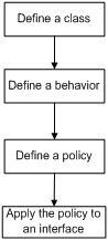
Defining a class
|
Step |
Command |
Remarks |
|
1. Enter system view. |
system-view |
N/A |
|
2. Create a class and enter class view. |
traffic classifier classifier-name [ operator { and | or } ] |
By default, the operator of a class is AND. The operator of a class can be AND or OR. · AND—A packet is assigned to a class only when the packet matches all the criteria in the class. · OR—A packet is assigned to a class if it matches any of the criteria in the class. |
|
3. Configure match criteria. |
if-match match-criteria |
For more information, see the if-match command in ACL and QoS Command Reference. |
Defining a traffic behavior
A traffic behavior is a set of QoS actions (such as traffic filtering, policing, and priority marking) to take on a class of traffic.
To define a traffic behavior:
|
Step |
Command |
|
1. Enter system view. |
system-view |
|
2. Create a traffic behavior and enter traffic behavior view |
traffic behavior behavior-name |
|
3. Configure actions in the traffic behavior. |
See the subsequent chapters, depending on the purpose of the traffic behavior: traffic policing, traffic filtering, and priority marking. |
Defining a policy
Associate a behavior with a class in a QoS policy to perform the actions defined in the behavior for the class of packets.
If an ACL is used in a traffic class, the permit/deny actions in ACL rules are ignored. Actions taken on matching packets are defined in the traffic behavior.
To associate a class with a behavior in a policy:
|
Step |
Command |
Remarks |
|
1. Enter system view. |
system-view |
N/A |
|
2. Create a policy and enter policy view. |
qos policy policy-name |
N/A |
|
3. Associate a class with a behavior in the policy. |
classifier classifier-name behavior behavior-name |
Repeat this step to create more class-behavior associations. |
Applying the QoS policy to an interface
A QoS policy applied to an interface takes effect on the traffic sent or received on the interface.
You can modify classes, behaviors, and class-behavior associations in a QoS policy even after it is applied. If a class uses an ACL for traffic classification, you can delete or modify the ACL.
When you apply the QoS policy to an interface, follow these guidelines:
· A policy can be applied to multiple interfaces, but only one policy can be applied in one direction (inbound or outbound) of an interface.
· The QoS policy applied to the outgoing traffic on an interface does not regulate local packets, which are critical protocol packets sent by the local system for operation maintenance. The most common local packets include link maintenance packets.
To apply the QoS policy to an interface:
|
Step |
Command |
|
1. Enter system view. |
system-view |
|
2. Enter interface view. |
interface interface-type interface-number |
|
3. Apply the policy to the interface. |
qos apply policy policy-name { inbound | outbound } |
Displaying and maintaining QoS policies
|
Task |
Command |
Remarks |
|
Display traffic class configuration. |
display traffic classifier user-defined [ classifier-name ] [ | { begin | exclude | include } regular-expression ] |
Available in any view. |
|
Display traffic behavior configuration. |
display traffic behavior user-defined [ behavior-name ] [ | { begin | exclude | include } regular-expression ] |
Available in any view. |
|
Display user-defined QoS policy configuration. |
display qos policy user-defined [ policy-name [ classifier classifier-name ] ] [ | { begin | exclude | include } regular-expression ] |
Available in any view. |
|
Display QoS policy configuration on interfaces. |
display qos policy interface [ interface-type interface-number ] [ inbound | outbound ] [ | { begin | exclude | include } regular-expression ] |
Available in any view. |
Overview
When a packet arrives, depending on your configuration, a device assigns a set of QoS priority parameters to the packet based on either a certain priority field carried in the packet or the port priority of the incoming port. This process is called "priority mapping." During this process, the device can modify the priority of the packet depending on device status. The set of QoS priority parameters decides the scheduling priority and forwarding priority of the packet.
Priority mapping is implemented with priority mapping tables and involves priorities such as 802.11e priority, 802.1p priority, DSCP, IP precedence, local precedence, and drop precedence.
Introduction to priorities
Priorities fall into the following types: priorities carried in packets, and priorities locally assigned for scheduling only.
The packet-carried priorities include 802.1p priority, DSCP precedence, IP precedence. These priorities have global significance and affect the forwarding priority of packets across the network. For more information about these priorities, see "Appendix."
The locally assigned priorities only have local significance. They are assigned by the device for scheduling only. The device supports only local precedence for locally assigned priorities. A local precedence value corresponds to an output queue. A packet with higher local precedence is assigned to a higher priority output queue to be preferentially scheduled.
Priority mapping tables
The device provides various types of priority mapping tables, or rather, priority mappings. By looking up a priority mapping table, the device decides which priority value is to assign to a packet for subsequent packet processing.
The default priority mapping tables (as shown in Appendix B Default priority mapping tables) are available for priority mapping. They are adequate in most cases. If a default priority mapping table cannot meet your requirements, you can modify the priority mapping table as required.
Priority mapping configuration tasks
You can configure priority mapping by using any of the following approaches:
· Configuring priority trust mode.
In this approach, you can configure a port to look up a certain priority, 802.1p for example, in incoming packets, in the priority mapping tables. If no packet priority is trusted, the port priority of the incoming port is used.
· Changing port priority.
By default, all ports are assigned the port priority of zero. By changing the port priority of a port, you change the priority of the incoming packets on the port.
Perform these tasks to configure priority mapping:
|
Task |
Remarks |
|
Optional. |
|
|
Configuring a port to trust packet priority for priority mapping |
Optional. |
|
Optional. |
Configuring a priority mapping table
The device provides the following types of priority mapping table.
Table 1 Priority mapping tables
|
Priority mapping |
Description |
|
dot11e-lp |
802.11e-local mapping table. |
|
dot1p-lp |
802.1p-local mapping table. |
|
dscp-lp |
DSCP-local mapping table. |
|
lp-dot11e |
Local-802.11e mapping table. |
|
lp-dot1p |
Local-802.1p mapping table. |
|
lp-dscp |
Local-DSCP mapping table. |
To configure a priority mapping table:
|
Step |
Command |
Remarks |
|
1. Enter system view. |
system-view |
N/A |
|
2. Enter priority mapping table view. |
qos map-table { dot11e-lp | dot1p-lp | dscp-lp | lp-dot11e | lp-dot1p | lp-dscp } |
N/A |
|
3. Configure the priority mapping table. |
import import-value-list export export-value |
Newly configured mappings overwrite the old ones. |
Configuring a port to trust packet priority for priority mapping
You can configure the device to trust a particular priority field carried in packets for priority mapping on ports.
When you configure the trusted packet priority type on an interface, use the following available keywords:
· auto—Automatically selects the priority of each received packet according to packet type for mapping. For Layer 2 packets, 802.1p priority is used. For Layer 3 packets, IP precedence is used.
· dot11e—Uses the 802.11e priority of received packets for mapping.
· dot1p—Uses the 802.1p priority of received packets for mapping.
· dscp—Uses the DSCP precedence of received IP packets for mapping.
To configure the trusted packet priority type on an interface:
|
Step |
Command |
Remarks |
|
1. Enter system view. |
system-view |
N/A |
|
2. Enter interface view or port group view. |
interface interface-type interface-number |
N/A |
|
3. Configure the trusted packet priority type for the interface. |
qos trust { auto | dot11e | dot1p | dscp } |
By default, the port priority is trusted. The dot11e keyword is available only on WLAN-BSS interfaces. |
Changing the port priority of an interface
If an interface does not trust any packet priority, the device uses its port priority to look for the set of priority parameters for the incoming packets. By changing port priority, you can prioritize traffic received on different interfaces.
To change the port priority of an interface:
|
Step |
Command |
Remarks |
|
1. Enter system view. |
system-view |
N/A |
|
2. Enter interface view. |
interface interface-type interface-number |
N/A |
|
3. Set the port priority of the interface. |
qos priority priority-value |
The default is 0. |
Displaying and maintaining priority mapping
|
Task |
Command |
Remarks |
|
Display priority mapping table configuration. |
display qos map-table [dot11e-lp | dot1p-lp | dscp-lp | lp-dot11e | lp-dot1p | lp-dscp ] [ | { begin | exclude | include } regular-expression ] |
Available in any view. |
|
Display the trusted packet priority type on a port. |
display qos trust interface [ interface-type interface-number ] [ | { begin | exclude | include } regular-expression ] |
Available in any view. |
Priority mapping configuration examples
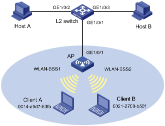
Network requirements
As shown in Figure 2, all departments access the Intranet through the same AP. Each department is configured with an independent WLAN name. These departments are assigned to different VLANs based on WLAN-BSS interfaces.
Configure priority mapping, so that the AP marks different priority values for traffic flows which are destined to wireless clients and received on the Ethernet interface of the AP.
The default priority mapping table of the AP is used.
Configuration procedure
|
|
NOTE: These configurations just apply to the traffic from the wired network to the wireless network. To regulate the traffic from the wireless network to the wired network, you should make priority marking configurations on the wireless ports on the AP. |
1. Configure the switch
# Create VLAN 2 and VLAN 3.
<Switch> system-view
[Switch] vlan 2
[Switch-vlan2] port gigabitethernet 1/0/2
[Switch-vlan2] quit
[Switch]vlan 3
[Switch-vlan3] port gigabitethernet 1/0/3
[Switch-vlan3] quit
[Switch]interface gigabitethernet1/0/1
[Switch-GigabitEthernet1/0/1] port link-type trunk
[Switch-GigabitEthernet1/0/1] port trunk permit vlan all
[Switch-GigabitEthernet1/0/1] quit
[Switch]
2. Configure the AP
# Enter system view.
<AP> system-view
# Configure a WLAN network for each of the two departments, with the SSID being PART1 and PART2 respectively. Bind the two WLAN networks to WLAN-BSS 1 and WLAN-BSS 2 respectively.
[AP] wlan service-template 1 clear
[AP-wlan-st-1] ssid PART1
[AP-wlan-st-1] service-template enable
[AP-wlan-st-1] quit
# Create interface WLAN-BSS 1.
[AP] interface wlan-bss 1
[AP-WLAN-BSS1] quit
[AP] interface wlan-radio 1/0/2
[AP-WLAN-Radio1/0/2] service-template 1 interface WLAN-BSS 1
[AP-wlan-st-1] quit
[AP] wlan service-template 2 clear
[AP-wlan-st-2] ssid PART2
[AP-wlan-st-2] service-template enable
[AP-wlan-st-2] quit
# Create interface WLAN-BSS 2.
[AP] interface wlan-bss 2
[AP-WLAN-BSS2] quit
[AP] interface wlan-radio 1/0/2
[AP-WLAN-Radio1/0/2] service-template 2 interface WLAN-BSS 2
[AP-wlan-st-2] quit
# Create a class named test1, and configure the class to match packets with their destination MAC addresses as 0014-a5d7-53fb, the MAC address of Client A.
[AP] traffic classifier test1
[AP-classifier-test1] if-match destination-mac 0014-a5d7-53fb
[AP-classifier-test1] quit
# Create a class named test2, and configure the class to match packets with their destination MAC addresses as 0021-2708-b50f, the MAC address of Client B.
[AP] traffic classifier test2
[AP-classifier-test2] if-match destination-mac 0021-2708-b50f
[AP-classifier-test2] quit
# Create a behavior named test1, and configure the action of setting the local precedence value to 5 for the behavior.
[AP] traffic behavior test1
[AP-behavior-test1] remark local-precedence 5
[AP-behavior-test1] quit
# Create a behavior named test2, and configure the action of setting the local precedence value to 7 for the behavior.
[AP] traffic behavior test2
[AP-behavior-test2] remark local-precedence 7
[AP-behavior-test2] quit
# Create a policy named test, associate class test1 with behavior test1, and associate class test2 with behavior test2.
[AP] qos policy test
[AP-qospolicy-test] classifier test1 behavior test1
[AP-qospolicy-test] classifier test2 behavior test2
[AP-qospolicy-test] quit
# Apply QoS policy test to the incoming traffic of GigabitEthernet 1/0/1.
[AP]interface GigabitEthernet 1/0/1
[AP-GigabitEthernet1/0/1] qos apply policy test inbound
[AP-GigabitEthernet1/0/1] quit
With these configurations completed, when the two wireless clients connecting to WLAN-BSS 1 and WLAN-BSS 2 copy files from Host A and Host B or use FTP to download files from Host A and Host B, because the priority of Client B is higher than the priority of Client A for the traffic from the wired side to the wireless side, you will find that the downloading rate of Client B connecting to WLAN-BSS 2 is faster than the downloading rate of Client A connecting to WLAN-BSS 1.
Overview
Traffic policing is a QoS technique that helps assign network resources, such as assign bandwidth. It increases network performance and user satisfaction. For example, you can configure a flow to use only the resources committed to it in a certain time range. This avoids network congestion caused by burst traffic.
Traffic policing limits the traffic rate and resource usage according to traffic specifications. Once a particular flow exceeds its specifications, such as assigned bandwidth, the flow is policed to make sure it is under the specifications. You can use token buckets for evaluating traffic specifications.
Traffic evaluation and token buckets
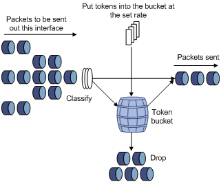
Token bucket features
A token bucket is analogous to a container that holds a certain number of tokens. Each token represents a certain forwarding capacity. The system puts tokens into the bucket at a constant rate. When the token bucket is full, the extra tokens cause the token bucket to overflow.
Evaluating traffic with the token bucket
A token bucket mechanism evaluates traffic by looking at the number of tokens in the bucket. If the number of tokens in the bucket is enough for forwarding the packets, the traffic conforms to the specification, and is called "conforming traffic." Otherwise, the traffic does not conform to the specification, and is called "excess traffic."
A token bucket has the following configurable parameters:
· Mean rate at which tokens are put into the bucket—The permitted average rate of traffic. It is usually set to the committed information rate (CIR).
· Burst size or the capacity of the token bucket—The maximum traffic size permitted in each burst. It is usually set to the committed burst size (CBS). The set burst size must be greater than the maximum packet size.
Each arriving packet is evaluated. In each evaluation, if the number of tokens in the bucket is enough, the traffic conforms to the specification and the tokens for forwarding the packet are taken away. If the number of tokens in the bucket is not enough, the traffic is excessive.
Complicated evaluation
You can set two token buckets, bucket C and bucket E, to evaluate traffic in a more complicated environment and achieve more policing flexibility. Traffic policing uses the following parameters:
· CIR—Rate at which tokens are put into bucket C. It sets the average packet transmission or forwarding rate allowed by bucket C.
· CBS—Size of bucket C, which specifies the transient burst of traffic that bucket C can forward.
· PIR—Rate at which tokens are put into bucket E, which specifies the average packet transmission or forwarding rate allowed by bucket E.
· EBS—Size of bucket E, which specifies the transient burst of traffic that bucket E can forward.
CBS is implemented with bucket C, and EBS with bucket E. In each evaluation, packets are measured against the following bucket scenarios:
· If bucket C has enough tokens, packets are colored green.
· If bucket C does not have enough tokens but bucket E has enough tokens, packets are colored yellow.
· If neither bucket C nor bucket E has sufficient tokens, packets are colored red.
Traffic policing
Traffic policing supports policing the inbound traffic and the outbound traffic.
A typical application of traffic policing is to supervise the specification of certain traffic entering a network and limit it within a reasonable range, or to "discipline" the extra traffic to prevent aggressive use of network resources by a certain application. For example, you can limit bandwidth for HTTP packets to less than 50% of the total. If the traffic of a certain session exceeds the limit, traffic policing can drop the packets or reset the IP precedence of the packets. Figure 3 shows an example of policing outbound traffic on an interface.
Traffic policing is widely used in policing traffic entering the networks of ISPs. It can classify the policed traffic and take predefined policing actions on each packet depending on the evaluation result:
· Forwarding the packet if the evaluation result is "conforming."
· Dropping the packet if the evaluation result is "excess."
· Forwarding the packet with its IP precedence re-marked if the evaluation result is "conforming."
Configuration procedure
|
Step |
Command |
|
1. Enter system view. |
system-view |
|
2. Create a class and enter class view. |
traffic classifier classifier-name [ operator { and | or } ] |
|
3. Configure match criteria. |
if-match match-criteria |
|
4. Return to system view. |
quit |
|
5. Create a behavior and enter behavior view. |
traffic behavior behavior-name |
|
6. Configure a traffic policing action. |
car cir committed-information-rate [ cbs committed-burst-size [ ebs excess-burst-size ] ] [ pir peak-information-rate ] [ green action ] [ red action ] |
|
7. Return to system view. |
quit |
|
8. Create a policy and enter policy view. |
qos policy policy-name |
|
9. Associate the class with the traffic behavior in the QoS policy. |
classifier classifier-name behavior behavior-name |
|
10. Return to system view. |
quit |
|
11. Apply the QoS policy to an interface. |
Traffic policing configuration example
Network requirements
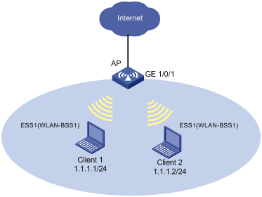
As shown in Figure 4, the AP is connected to the Internet through interface GigabitEthernet 1/0/1. Client 1 and Client 2 can access the Internet through the AP.
Perform traffic control on the AP for traffic received from clients to satisfy the following requirements:
· Limit the rate of traffic from Client 1 to 54 kbps, and mark the excess traffic with local precedence value 0 and then transmit the traffic.
· Limit the rate of traffic from Client 2 to 500 kbps, and drop the excess traffic.
· Limit the rate of outgoing traffic accessing the Internet to 1000 kbps on GigabitEthernet 1/0/1, and drop the excess traffic.
Configuration procedure
# Configure ACL 2001 and ACL 2002 to match traffic from Client 1 and Client 2, respectively.
[AP] acl number 2001
[AP-acl-basic-2001] rule permit source 1.1.1.1 0
[AP-acl-basic-2001] quit
[AP] acl number 2002
[AP-acl-basic-2002] rule permit source 1.1.1.2 0
[AP-acl-basic-2002] quit
# Create a QoS policy named qp to perform traffic policing for traffic from Client 1 and Client 2, respectively.
[AP] traffic classifier tc1
[AP-classifier-tc1] if-match acl 2001
[AP-classifier-tc1] quit
[AP] traffic behavior tb1
[AP-behavior-tb1] car cir 54 cbs 1875 ebs 0 green pass red remark-lp-pass 0
[AP-behavior-tb1] quit
[AP] traffic classifier tc2
[AP-classifier-tc2] if-match acl 2002
[AP-classifier-tc2] quit
[AP] traffic behavior tb2
[AP-behavior-tb2] car cir 500 cbs 32000 ebs 0 green pass red discard
[AP behavior-tb2] quit
[AP] qos policy qp
[AP-qospolicy-qp] classifier tc1 behavior tb1
[AP-qospolicy-qp] classifier tc2 behavior tb2
[AP-qospolicy-qp] quit
# Apply the policy named qp to the inbound direction of WLAN-BSS 1.
[AP] interface WLAN-BSS 1
[AP-WLAN-BSS1] qos apply policy qp inbound
[AP-WLAN-BSS1] quit
# Create a QoS policy named qp3 to perform traffic policing for traffic from AP to the Internet.
[AP] traffic classifier tc3
[AP-classifier-tc3] if-match any
[AP-classifier-tc3] quit
[AP] traffic behavior tb3
[AP-behavior-tb3] car cir 1000 cbs 65000 ebs 0 red discard
[AP behavior-tb3] quit
[AP] qos policy qp3
[AP-qospolicy-qp3] classifier tc3 behavior tb3
[AP-qospolicy-qp3] quit
# Apply the policy named qp3 to the outbound direction of GigabitEthernet 1/0/1.
[AP]interface GigabitEthernet1/0/1
[AP-GigabitEthernet1/0/1] qos apply policy qp3 outbound
[AP-GigabitEthernet1/0/1] quit
You can filter in or filter out a class of traffic by associating the class with a traffic filtering action. For example, you can filter packets sourced from a specific IP address according to network status.
Configuration procedure
To configure traffic filtering:
|
Step |
Command |
|
1. Enter system view. |
system-view |
|
2. Create a class and enter class view. |
traffic classifier classifier-name [ operator { and | or } ] |
|
3. Configure match criteria. |
if-match match-criteria |
|
4. Return to system view. |
quit |
|
5. Create a behavior and enter behavior view. |
traffic behavior behavior-name |
|
6. Configure the traffic filtering action. |
filter { deny | permit } |
|
7. Return to system view. |
quit |
|
8. Create a policy and enter policy view. |
qos policy policy-name |
|
9. Associate the class with the traffic behavior in the QoS policy. |
classifier classifier-name behavior behavior-name |
|
10. Return to system view. |
quit |
|
11. Apply the QoS policy. |
|
|
12. Display the traffic filtering configuration. |
display traffic behavior user-defined [ behavior-name ] [ | { begin | exclude | include } regular-expression ] |
If a traffic behavior has the filter deny action, all the other actions in the traffic behavior do not take effect.
Traffic filtering configuration example
Network requirements
As shown in Figure 5, configure traffic filtering on interface WLAN-BSS1 to drop the incoming TCP packets with source port numbers other than 21.

Configuration procedure
# Create advanced ACL 3000, and configure a rule to match TCP packets whose source port number is not 21.
<DeviceA> system-view
[DeviceA] acl number 3000
[DeviceA-acl-adv-3000] rule 0 permit tcp source-port neq 21
[DeviceA-acl-adv-3000] quit
# Create a class named classifier_1, and use ACL 3000 as the match criterion in the class.
[DeviceA] traffic classifier classifier_1
[DeviceA-classifier-classifier_1] if-match acl 3000
[DeviceA-classifier-classifier_1] quit
# Create a behavior named behavior_1, and configure the traffic filtering action to drop packets.
[DeviceA] traffic behavior behavior_1
[DeviceA-behavior-behavior_1] filter deny
[DeviceA-behavior-behavior_1] quit
# Create a policy named policy, and associate class classifier_1 with behavior behavior_1 in the policy.
[DeviceA] qos policy policy
[DeviceA-qospolicy-policy] classifier classifier_1 behavior behavior_1
[DeviceA-qospolicy-policy] quit
# Apply the policy policy to the incoming traffic of interface WLAN-BSS 1.
[DeviceA] interface wlan-bss 1
[DeviceA-WLAN-BSS1] qos apply policy policy inbound
Priority marking sets the priority fields or flag bits of packets to modify the priority of traffic. For example, you can use priority marking to set IP precedence or DSCP for a class of IP traffic to change its transmission priority in the network.
Configuration procedure
To configure priority marking:
|
Step |
Command |
Remarks |
|
1. Enter system view. |
system-view |
N/A |
|
2. Create a class and enter class view. |
traffic classifier classifier-name [ operator { and | or } ] |
N/A |
|
3. Configure match criteria. |
if-match match-criteria |
N/A |
|
4. Return to system view. |
quit |
N/A |
|
5. Create a behavior and enter behavior view. |
traffic behavior behavior-name |
N/A |
|
6. Set the 802.1p priority for packets. |
remark dot1p 8021p |
Optional. |
|
7. Set the local precedence for packets. |
remark local-precedence local-precedence |
Optional. |
|
8. Return to system view. |
quit |
N/A |
|
9. Create a policy and enter policy view. |
qos policy policy-name |
N/A |
|
10. Associate the class with the traffic behavior in the QoS policy. |
classifier classifier-name behavior behavior-name |
N/A |
|
11. Return to system view. |
quit |
N/A |
|
12. Apply the QoS policy. |
N/A |
|
|
13. Display the priority marking configuration. |
display traffic behavior user-defined [ behavior-name ] [ | { begin | exclude | include } regular-expression ] |
Optional. Available in any view. |
Priority marking configuration example
Network requirements
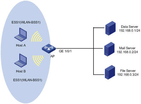
As shown in Figure 6, the enterprise network of a company interconnects hosts with servers through the AP. The network is described as follows:
· Host A and Host B are connected to the WLAN-BSS interface of the AP.
· The data server, mail server, and file server are connected to GigabitEthernet 1/0/1 of the AP.
Configure priority marking on the AP to satisfy the following requirements:
|
Traffic source |
Destination |
Processing priority |
|
Host A, B |
Data server |
High |
|
Host A, B |
Mail server |
Medium |
|
Host A, B |
File server |
Low |
Configuration procedure
# Create advanced ACL 3000, and configure a rule to match packets with source IP address 192.168.0.1.
<AP> system-view
[AP] acl number 3000
[AP-acl-adv-3000] rule permit ip source 192.168.0.1 0
[AP-acl-adv-3000] quit
# Create advanced ACL 3001, and configure a rule to match packets with source IP address 192.168.0.2.
[AP] acl number 3001
[AP-acl-adv-3001] rule permit ip source 192.168.0.2 0
[AP-acl-adv-3001] quit
# Create advanced ACL 3002, and configure a rule to match packets with source IP address 192.168.0.3.
[AP] acl number 3002
[AP-acl-adv-3002] rule permit ip source 192.168.0.3 0
[AP-acl-adv-3002] quit
# Create a class named classifier_dbserver, and use ACL 3000 as the match criterion in the class.
[AP] traffic classifier classifier_dbserver
[AP-classifier-classifier_dbserver] if-match acl 3000
[AP-classifier-classifier_dbserver] quit
# Create a class named classifier_mserver, and use ACL 3001 as the match criterion in the class.
[AP] traffic classifier classifier_mserver
[AP-classifier-classifier_mserver] if-match acl 3001
[AP-classifier-classifier_mserver] quit
# Create a class named classifier_fserver, and use ACL 3002 as the match criterion in the class.
[AP] traffic classifier classifier_fserver
[AP-classifier-classifier_fserver] if-match acl 3002
[AP-classifier-classifier_fserver] quit
# Create a behavior named behavior_dbserver, and configure the action of setting the local precedence value to 6.
[AP] traffic behavior behavior_dbserver
[AP-behavior-behavior_dbserver] remark local-precedence 6
[AP-behavior-behavior_dbserver] quit
# Create a behavior named behavior_mserver, and configure the action of setting the local precedence value to 4.
[AP] traffic behavior behavior_mserver
[AP-behavior-behavior_mserver] remark local-precedence 4
[AP-behavior-behavior_mserver] quit
# Create a behavior named behavior_fserver, and configure the action of setting the local precedence value to 2.
[AP] traffic behavior behavior_fserver
[AP-behavior-behavior_fserver] remark local-precedence 2
[AP-behavior-behavior_fserver] quit
# Create a policy named policy_server, and associate classes with behaviors in the policy.
[AP] qos policy policy_server
[AP-qospolicy-policy_server] classifier classifier_dbserver behavior behavior_dbserver
[AP-qospolicy-policy_server] classifier classifier_mserver behavior behavior_mserver
[AP-qospolicy-policy_server] classifier classifier_fserver behavior behavior_fserver
[AP-qospolicy-policy_server] quit
# Apply the policy named policy_server to the incoming traffic of GigabitEthernet 1/0/1.
[AP] interface gigabitethernet1/0/1
[AP-GigabitEthernet1/0/1] qos apply policy policy_server inbound
[AP-GigabitEthernet1/0/1] quit
# Configure interface WLAN-BSS1 to use the 802.11 priority of incoming packets for priority mapping.
[AP] interface WLAN-BSS1
[AP-WLAN-BSS1] qos trust dot11e
[AP-WLAN-BSS1] quit
Appendix A Acronyms
Table 2 Acronyms
|
Acronym |
Full spelling |
|
BE |
Best Effort |
|
CAR |
Committed Access Rate |
|
CBS |
Committed Burst Size |
|
CIR |
Committed Information Rate |
|
DiffServ |
Differentiated Service |
|
DSCP |
Differentiated Services Code Point |
|
EBS |
Excess Burst Size |
|
IntServ |
Integrated Service |
|
ISP |
Internet Service Provider |
|
PIR |
Peak Information Rate |
|
QoS |
Quality of Service |
|
ToS |
Type of Service |
|
TP |
Traffic Policing |
Appendix B Default priority mapping tables
Table 3 Default lp-dot11e priority mapping table
|
Input priority value |
lp-dot11e mapping |
|
Local precedence (lp) |
802.11e priority (dot11e) |
|
0 |
2 |
|
1 |
0 |
|
2 |
1 |
|
3 |
3 |
|
4 |
4 |
|
5 |
5 |
|
6 |
6 |
|
7 |
7 |
Table 4 Default dot1p-lp priority mapping table
|
Input priority value |
dot1p-lp mapping |
|
802.1p priority (dot1p) |
Local precedence (lp) |
|
0 |
2 |
|
1 |
0 |
|
2 |
1 |
|
3 |
3 |
|
4 |
4 |
|
5 |
5 |
|
6 |
6 |
|
7 |
7 |
Table 5 Default dscp-lp priority mapping table
|
Input priority value |
dscp-lp mapping |
|
DSCP |
Local precedence (lp) |
|
0 to 7 |
0 |
|
8 to 15 |
1 |
|
16 to 23 |
2 |
|
24 to 31 |
3 |
|
32 to 39 |
4 |
|
40 to 47 |
5 |
|
48 to 55 |
6 |
|
56 to 63 |
7 |
Table 6 Default lp-dot1p, lp-dscp priority, and lp-dot11e mapping tables
|
Input priority value |
lp-dot1p mapping |
lp-dscp mapping |
lp-dot11e mapping |
|
Local precedence (lp) |
802.1p priority (dot1p) |
DSCP |
802.11e priority (dot11e) |
|
0 |
1 |
0 |
1 |
|
1 |
2 |
8 |
2 |
|
2 |
0 |
16 |
0 |
|
3 |
3 |
24 |
3 |
|
4 |
4 |
32 |
4 |
|
5 |
5 |
40 |
5 |
|
6 |
6 |
48 |
6 |
|
7 |
7 |
56 |
7 |
Appendix C Introduction to packet precedences
IP precedence and DSCP values
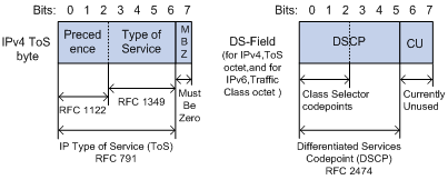
As shown in Figure 7, the ToS field in the IPv4 header contains eight bits, where the first three bits (0 to 2) represent IP precedence from 0 to 7. The Traffic Classes field in the IPv6 header contains eight bits, where the first three bits (0 to 2) represent IP precedence from 0 to 7. According to RFC 2474, the ToS field in the IPv4 header or the Traffic Classes field in the IPv6 header is redefined as the DS field, where a DSCP value is represented by the first six bits (0 to 5) and is in the range 0 to 63. The remaining two bits (6 and 7) are reserved.
Table 7 IP precedence
|
IP precedence (decimal) |
IP precedence (binary) |
Description |
|
0 |
000 |
Routine |
|
1 |
001 |
priority |
|
2 |
010 |
immediate |
|
3 |
011 |
flash |
|
4 |
100 |
flash-override |
|
5 |
101 |
critical |
|
6 |
110 |
internet |
|
7 |
111 |
network |
Table 8 DSCP values
|
DSCP value (decimal) |
DSCP value (binary) |
Description |
|
46 |
101110 |
ef |
|
10 |
001010 |
af11 |
|
12 |
001100 |
af12 |
|
14 |
001110 |
af13 |
|
18 |
010010 |
af21 |
|
20 |
010100 |
af22 |
|
22 |
010110 |
af23 |
|
26 |
011010 |
af31 |
|
28 |
011100 |
af32 |
|
30 |
011110 |
af33 |
|
34 |
100010 |
af41 |
|
36 |
100100 |
af42 |
|
38 |
100110 |
af43 |
|
8 |
001000 |
cs1 |
|
16 |
010000 |
cs2 |
|
24 |
011000 |
cs3 |
|
32 |
100000 |
cs4 |
|
40 |
101000 |
cs5 |
|
48 |
110000 |
cs6 |
|
56 |
111000 |
cs7 |
|
0 |
000000 |
be (default) |
802.1p priority
802.1p priority lies in the Layer 2 header and applies to occasions where Layer 3 header analysis is not needed and QoS must be assured at Layer 2.
Figure 8 An Ethernet frame with an 802.1Q tag header
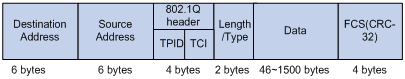
As shown in Figure 8, the four-byte 802.1Q tag header consists of the TPID (two bytes in length), whose value is 0x8100, and the TCI (two bytes in length). Figure 9 shows the format of the 802.1Q tag header. The Priority field in the 802.1Q tag header is called the "802.1p priority," because its use is defined in IEEE 802.1p. Table 9 shows the values for 802.1p priority.
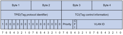
Table 9 Description on 802.1p priority
|
802.1p priority (decimal) |
802.1p priority (binary) |
Description |
|
0 |
000 |
best-effort |
|
1 |
001 |
background |
|
2 |
010 |
spare |
|
3 |
011 |
excellent-effort |
|
4 |
100 |
controlled-load |
|
5 |
101 |
video |
|
6 |
110 |
voice |
|
7 |
111 |
network-management |
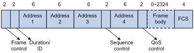
802.11e priority
To provide QoS services on WLAN, the 802.11e standard was developed. IEEE 802.11e is a MAC-layer enhancement to IEEE 802.11. IEEE 802.11e adds a 2-byte QoS Control field to the 802.11e MAC frame header. Three bits of the QoS control field represents the 802.11e priority, which ranges from 0 to 7.
Figure 10 802.11e frame structure