- Table of Contents
- Related Documents
-
| Title | Size | Download |
|---|---|---|
| 02-Appendix LEDs and ports | 182.92 KB |
Appendix LEDs and ports
LEDs
|
Mark |
Status |
Description |
|
|
|
Green |
Flashing at 1 Hz |
The AP is booting. NOTE: When the AP operates as a fit AP, it is always in this state before it is registered to an AC. |
|
Breathing |
A client is connected to the 2.4G radio. |
||
|
Blue |
Flashing at 0.25 GHz |
The AP has been booted, and is in standby state (no client is connected to the AP). NOTE: When the AP operates as a fit AP, this state indicates the AP has been registered to an AC. |
|
|
Flashing at 2 GHz |
The AP is updating its system software image. This status is available only when the AP operates as a fit AP. |
||
|
Breathing |
A client is connected to the 5G radio. |
||
|
Orange |
Steady on |
An initialization exception has occurred to the AP. |
|
|
Flashing at 1 Hz |
The AP cannot detect any radio interface. |
||
|
Alternating green and blue |
Alternating flashing at 1 Hz |
Blinking mode. NOTE: When the fit AP associated with the AC receives the blinking command sent by the AC, it flashes green and blue to show the fit AP has been associated with the AC. |
|
|
Breathing green and blue alternatively |
Clients are connected to both the 2.4G and 5G radios. |
||
|
|
NOTE: For more information about the blink mode, see H3C WX Series Access Controllers Configuration Guides. |
Ports
The AP provides the following ports:
· One console port
· Two 10/100/1000 Mbps copper Ethernet ports
· One power port
· Eight antenna connectors
|
|
NOTE: The AP also has a reset button and a security slot. The security slot is 7 × 3 mm (0.28 × 0.12 in) in size. |
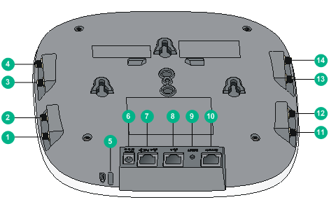
Figure 1 Ports on the AP
|
(1 to 4) Antenna connectors 1 to 4 |
(5) Security slot |
|
(6) Power port |
(7) 10/100/1000 Mbps copper Ethernet port 1 |
|
(8) 10/100/1000 Mbps copper Ethernet port 2 |
(9) Reset button |
|
(10) Console port |
(11 to 14) Antenna connectors 5 to 8 |
Table 2 Port description
|
Port mark |
Standards and protocols |
Description |
|
ANT-1/2/3/4/5/6/7/8 |
· IEEE802.11a · IEEE802.11b · IEEE802.11g · IEEE802.11n · IEEE802.11ac |
The antenna connector is used for feeder line connection. |
|
ETH1 |
· IEEE802.3 · IEEE802.3u · IEEE802.3af |
The Ethernet port can act as an uplink interface to access the Internet or MAN, and as an 802.3af PoE port at the same time. It is represented by interface GE1/0/1. |
|
ETH2 |
· IEEE802.3 · IEEE802.3u |
The Ethernet port can act as an uplink interface to access the Internet or MAN. It is represented by interface GE1/0/2. |
|
DC 48V |
N/A |
The port receives +48 VDC power from the local supply. |
|
CONSOLE |
RS/EIA-232 |
The console port is used for configuration and management. When the AP acts as a fit AP, only the maintenance staff can use the console port. |