- Table of Contents
- Related Documents
-
| Title | Size | Download |
|---|---|---|
| 02-INT configuration | 191.01 KB |
Restrictions and guidelines: INT configuration
Display and maintenance commands for INT
Example: Configuring basic INT
Example: Configuring enhanced INT
Configuring INT
About INT
The Inband Network Telemetry (INT) feature is a network monitoring technology designed to collect data from the device. The device sends data to a collector in real time for device performance monitoring and network monitoring.
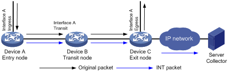
As shown in Figure 1, the nodes in an INT network perform the following functions:
1. The entry node samples matching packets received on the ingress interface according to a QoS policy, and mirrors sampled packets to the INT processor for adding time stamps. Then, the entry node encapsulates the sampled packets as INT packets and sends them to the transit node.
2. The transit node sends the INT packets to the INT processor, adds a time stamp to the INT packets, and sends them to the exit node.
3. The exit node sends the INT packets to the INT processor, adds a time stamp to the INT packets, encapsulates the INT packets with the specified IP address, port number, and VLAN ID, and sends them to the collector.
4. The collector analyzes QoS metrics such as link delay according to the time stamp carried in the INT packets.
Before an INT packet is encapsulated on the exit node, its IP addresses in the packet header are not modified. An INT packet takes the same path as its original packet and is used to measure the link delay.
Restrictions and guidelines: INT configuration
The switch can act as entry nodes, transit nodes, and exit nodes.
Enhanced INT is supported only in IP networks.
As a best practice to configure INT, first configure the transit node and exit node, and then the entry node.
Configuring basic INT
Configuring the entry node
Specifying a device ID for the entry node
1. Enter system view.
system-view
2. Specify a device ID for the entry node.
telemetry ifa device-id address
By default, the entry node does not have a device ID.
Specifying an interface on the entry node as the ingress interface
1. Enter system view.
system-view
2. Enter interface view.
interface interface-type interface-number
3. Specify the interface as the ingress interface.
telemetry ifa role ingress
By default, an interface is not used as the ingress interface.
Configuring traffic mirroring to the INT processor
1. Define a traffic class.
a. Enter system view.
system-view
b. Create a traffic class and enter traffic class view.
traffic classifier classifier-name [ operator { and | or } ]
c. Configure a match criterion.
if-match match-criteria
By default, no match criterion is configured.
For more information about the if-match command, see QoS commands in ACL and QoS Command Reference.
d. Return to system view.
quit
2. Define a traffic behavior.
a. Create a traffic behavior and enter traffic behavior view.
traffic behavior behavior-name
b. Configure the action of mirroring traffic to the INT processor.
mirror-to ifa-processor [ sampler sampler-name ]
By default, no traffic mirroring action is configured.
For more information about this command, see flow mirroring commands in Network Management and Monitoring Command Reference.
c. Return to system view.
quit
3. Define a QoS policy.
a. Create a QoS policy and enter QoS policy view.
qos [ mirroring ] policy policy-name
b. Associate the traffic class with the traffic behavior in the QoS policy.
classifier classifier-name behavior behavior-name
By default, a traffic class is not associated with a traffic behavior.
c. Return to system view.
quit
4. Apply the QoS policy to the inbound direction of the ingress interface.
a. Enter interface view.
interface interface-type interface-number
b. Apply the QoS policy to the inbound direction of the interface.
qos apply [ mirroring ] policy policy-name inbound
By default, no QoS policy is applied to an interface.
5. (Optional.) Display the traffic mirroring configuration.
display traffic behavior user-defined [ behavior-name ]
Enabling INT globally
1. Enter system view.
system-view
2. Enable INT globally.
telemetry ifa global enable
By default, INT is enabled globally.
Configuring the transit node
Specifying a device ID for the transit node
1. Enter system view.
system-view
2. Specify a device ID for the transit node.
telemetry ifa device-id address
By default, the transit node does not have a device ID.
Specifying an interface on the transit node as the transit interface
1. Enter system view.
system-view
2. Enter interface view.
interface interface-type interface-number
3. Specify the interface as the transit interface.
telemetry ifa role transit
By default, an interface is not used as the transit interface.
Enabling INT globally
1. Enter system view.
system-view
2. Enable INT globally.
telemetry ifa global enable
By default, INT is enabled globally.
Configuring the exit node
Specifying a device ID for the exit node
1. Enter system view.
system-view
2. Specify a device ID for the exit node.
telemetry ifa device-id address
By default, the exit node does not have a device ID.
Specifying an interface on the exit node as the egress interface
1. Enter system view.
system-view
2. Enter interface view.
interface interface-type interface-number
3. Specify the interface as the egress interface.
telemetry ifa role egress
By default, an interface is not used as the egress interface..
Configuring addressing parameters to encapsulate in INT packets sent to the collector
1. Enter system view.
system-view
2. Configure addressing parameters to encapsulate in INT packets sent to the collector.
telemetry ifa collector source source-address destination dest-address source-port port destination-port port [ vlan vlan-id ]
By default, no addressing parameters are configured for INT packets.
Enabling INT globally
1. Enter system view.
system-view
2. Enable INT globally.
telemetry ifa global enable
By default, INT is enabled globally.
Configuring enhanced INT
About enhanced INT
Enhanced INT enhances basic INT in the following aspects:
· Uses ACLs to replace QoS policies to simplify configuration.
· Applies INT actions directly to the input interface of traffic, which replaces role configuration.
· Can collect the timestamp on the exit node.
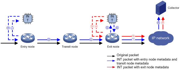
As shown in Figure 2, the nodes in enhanced INT perform the following functions:
1. The entry node samples ACL-matched packets received on the input interface, and mirrors sampled packets to the INT processor. Then, the INT processor adds an INT header to the sampled packets and sends them back to the input interface as INT packets by using internal loopback. The input interface identifies the looped back packets by using the ACL, adds collected metadata to the packets, and sends them to the output interface. The output interface adds collected metadata to the received packets and sends them to the transit node.
2. The transit node adds collected metadata to ACL-matched packets received on the input interface, and sends them to the output interface. The output interface adds collected metadata to the received packets and sends them to the exit node.
3. The entry node processes INT packets and original packets differently.
? The entry node samples ACL-matched INT packets received on the input interface, and mirrors sampled packets to the INT processor. The INT processor encapsulates the INT packets and sends them to the output interface, which sends them to the collector. The INT packets carry entry node metadata and transit node metadata.
? The entry node samples ACL-matched original packets received on the input interface, and mirrors sampled packets to the INT processor. Then, the INT processor adds an INT header to the sampled packets and sends them back to the input interface as INT packets by using internal loopback. The input interface identifies the looped back packets by using the ACL, adds collected metadata to the packets, and sends them to the output interface. The output interface adds collected metadata to the received packets and sends them to the next hop. The IP network sends the packets to the collector. The INT packets carry exit node metadata.
Configuring the entry node
Specifying a device ID for the entry node
1. Enter system view.
system-view
2. Specify a device ID for the entry node.
telemetry ifa device-id address
By default, the entry node does not have a device ID.
Configuring an action of mirroring original packets on the input interface to the INT processor
1. Enter system view.
system-view
2. Enter interface view.
interface interface-type interface-number
3. Mirror original packets on the input interface to the INT processor.
telemetry ifa ifa-id [ acl [ ipv6 | mac | user-defined ] { acl-number | name acl-name } ] action mirror-to-processor [ sampler sampler-name ]
By default, no INT action is configured.
Enabling internal loopback on an interface
1. Enter system view.
system-view
2. Enter interface view.
interface interface-type interface-number
3. Enable internal loopback on the interface.
telemetry ifa loopback
By default, internal loopback is disabled on an interface.
Configuring an action of adding collected metadata to looped back traffic on the input interface
1. Enter system view.
system-view
2. Enter interface view.
interface interface-type interface-number
3. Add collected metadata to looped back traffic on the interface.
telemetry ifa ifa-id acl user-defined { acl-number | name acl-name } local-loopback action add-metadata
By default, no INT action is configured.
If an ACL is specified in the action of mirroring original packets to the INT processor, the ACL specified in this command must contain the same traffic match criteria as that ACL and plus the statement to match the INT flag. The traffic match criteria and the statement to match the INT flag must be in the same ACL rule. For example, if the rule in the ACL in the action of mirroring original packets is rule permit tcp source 10.0.0.3 0, the rule in the ACL in this command must be rule permit tcp source 10.0.0.3 0 ifa l5 aaaaaaaabbbbbbbb ffffffffffffffff 0.
Enabling INT globally
1. Enter system view.
system-view
2. Enable INT globally.
telemetry ifa global enable
By default, INT is enabled globally.
Configuring the transit node
Specifying a device ID for the transit node
1. Enter system view.
system-view
2. Specify a device ID for the transit node.
telemetry ifa device-id address
By default, the transit node does not have a device ID.
Configuring an action of adding collected metadata to incoming packets on the input interface
1. Enter system view.
system-view
2. Enter interface view.
interface interface-type interface-number
3. Add collected metadata to incoming packets on the interface.
telemetry ifa ifa-id acl user-defined { acl-number | name acl-name } action add-metadata
By default, no INT action is configured.
If an ACL is specified in the action of mirroring original packets on the entry node to the INT processor, the ACL specified in this command must contain the same traffic match criteria as that ACL and plus the statement to match the INT flag. The traffic match criteria and the statement to match the INT flag must be in the same ACL rule. For example, if the rule in the ACL in the action of mirroring original packets is rule permit tcp source 10.0.0.3 0, the rule in the ACL in this command must be rule permit tcp source 10.0.0.3 0 ifa l5 aaaaaaaabbbbbbbb ffffffffffffffff 0.
Enabling INT globally
1. Enter system view.
system-view
2. Enable INT globally.
telemetry ifa global enable
By default, INT is enabled globally.
Configuring the exit node
Specifying a device ID for the exit node
1. Enter system view.
system-view
2. Specify a device ID for the exit node.
telemetry ifa device-id address
By default, the exit node does not have a device ID.
Configuring an action of mirroring INT packets on the input interface to the INT processor and dropping the original INT packets
1. Enter system view.
system-view
2. Enter interface view.
interface interface-type interface-number
3. Mirror INT packets on the interface to the INT processor and drop original INT packets.
telemetry ifa ifa-id acl user-defined { acl-number | name acl-name } action mirror-to-processor drop
By default, no INT action is configured.
If an ACL is specified in the action of mirroring original packets on the entry node to the INT processor, the ACL specified in this command must contain the same traffic match criteria as that ACL and plus the statement to match the INT flag. The traffic match criteria and the statement to match the INT flag must be in the same ACL rule. For example, if the rule in the ACL in the action of mirroring original packets is rule permit tcp source 10.0.0.3 0, the rule in the ACL in this command must be rule permit tcp source 10.0.0.3 0 ifa l5 aaaaaaaabbbbbbbb ffffffffffffffff 0.
Configuring addressing parameters to encapsulate in INT packets sent to the collector
1. Enter system view.
system-view
2. Configure addressing parameters to encapsulate in INT packets sent to the collector.
telemetry ifa collector source source-address destination dest-address source-port port destination-port port [ vlan vlan-id ]
By default, no addressing parameters are configured for INT packets.
Configuring an action of mirroring original packets on the input interface to the INT processor
1. Enter system view.
system-view
2. Enter interface view.
interface interface-type interface-number
3. Mirror original packets on the input interface to the INT processor.
telemetry ifa ifa-id [ acl [ ipv6 | mac | user-defined ] { acl-number | name acl-name } ] action mirror-to-processor [ sampler sampler-name ]
By default, no INT action is configured.
If an ACL is specified in the action of mirroring original packets on the entry node to the INT processor, the ACL specified in this command must contain the same traffic match criteria as that ACL.
Enabling internal loopback on an interface
1. Enter system view.
system-view
2. Enter interface view.
interface interface-type interface-number
3. Enable internal loopback on the interface.
telemetry ifa loopback
By default, internal loopback is disabled on an interface.
Configuring an action of adding collected metadata to looped back traffic on the input interface
1. Enter system view.
system-view
2. Enter interface view.
interface interface-type interface-number
3. Mirror original packets on the input interface to the INT processor.
telemetry ifa ifa-id acl user-defined { acl-number | name acl-name } local-loopback action add-metadata
By default, no INT action is configured.
If an ACL is specified in the action of mirroring original packets on the exit node to the INT processor, the ACL specified in this command must contain the same traffic match criteria as that ACL and plus the statement to match the INT flag. The traffic match criteria and the statement to match the INT flag must be in the same ACL rule. For example, if the rule in the ACL in the action of mirroring original packets is rule permit tcp source 10.0.0.3 0, the rule in the ACL in this command must be rule permit tcp source 10.0.0.3 0 ifa l5 aaaaaaaabbbbbbbb ffffffffffffffff 0.
Enabling INT globally
1. Enter system view.
system-view
2. Enable INT globally.
telemetry ifa global enable
By default, INT is enabled globally.
Display and maintenance commands for INT
Execute display commands in any view.
|
Task |
Command |
|
Display information about QoS policies applied to interfaces (see ACL and QoS Command Reference). |
In standalone mode: display qos [ mirroring ] policy interface [ interface-type interface-number ] [ slot slot-number ] inbound In IRF mode: display qos [ mirroring ] policy interface [ interface-type interface-number ] [ chassis chassis-number slot slot-number ] inbound |
|
Display INT configuration. |
display telemetry ifa |
INT configuration examples
Example: Configuring basic INT
Network configuration
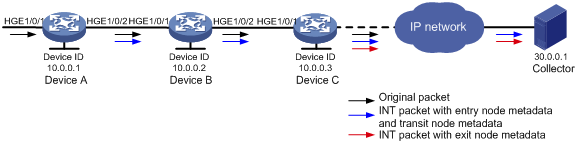
As shown in Figure 3, configure basic INT to test the link delay.

Procedure
1. Assign IP addresses to interfaces and configure routes. Make sure the network connections are available. (Details not shown.)
2. Configure Device A:
# Specify 10.0.0.1 as the device ID of the entry node.
<DeviceA> system-view
[DeviceA] telemetry ifa device-id 10.0.0.1
# Specify HundredGigE 1/0/1 as the ingress interface.
[DeviceA] interface hundredgige 1/0/1
[DeviceA-HundredGigE1/0/1] telemetry ifa role ingress
[DeviceA-HundredGigE1/0/1] quit
# Create a sampler named samp in random sampling mode, and set the sampling rate to 8. One packet from 256 packets is selected.
[DeviceA] sampler samp mode random packet-interval n-power 8
# Create a traffic class named classifier1, and use destination MAC address a08c-fdd7-fd99 as the match criterion in the traffic class.
[DeviceA] traffic classifier classifier1
[DeviceA-classifier-classifier1] if-match destination-mac a08c-fdd7-fd99
[DeviceA-classifier-classifier1] quit
# Create a traffic behavior named behavior1, and configure the action of mirroring traffic to the INT processor.
[DeviceA] traffic behavior behavior1
[DeviceA-behavior-behavior1] mirror-to ifa-processor sampler samp
[DeviceA-behavior-behavior 1] quit
# Create a QoS policy named ifa1, and associate traffic class classifier1 with traffic behavior behavior1 in the QoS policy.
[DeviceA] qos policy ifa1
[DeviceA-qospolicy-ifa1] classifier classifier1 behavior behavior1
[DeviceA-qospolicy-ifa1] quit
# Apply QoS policy ifa1 to the incoming traffic of HundredGigE 1/0/1.
[DeviceA] interface hundredgige 1/0/1
[DeviceA-HundredGigE1/0/1] qos apply policy ifa1 inbound
[DeviceA-HundredGigE1/0/1] quit
# Enable INT globally.
[DeviceA] telemetry ifa global enable
3. Configure Device B:
# Specify 10.0.0.2 as the device ID of the transit node.
<DeviceB> system-view
[DeviceB] telemetry ifa device-id 10.0.0.2
# Specify HundredGigE 1/0/1 as the transit interface.
[DeviceB] interface hundredgige 1/0/1
[DeviceB-HundredGigE1/0/1] telemetry ifa role transit
[DeviceB-HundredGigE1/0/1] quit
# Enable INT globally.
[DeviceB] telemetry ifa global enable
4. Configure Device C:
# Specify 10.0.0.3 as the device ID of the exit node.
<DeviceC> system-view
[DeviceC] telemetry ifa device-id 10.0.0.3
# Specify HundredGigE 1/0/1 as the egress interface.
[DeviceC] interface hundredgige 1/0/1
[DeviceC-HundredGigE1/0/1] telemetry ifa role egress
[DeviceC-HundredGigE1/0/1] quit
# Configure addressing parameters to encapsulate in INT packets sent to the collector.
[DeviceC] telemetry ifa collector source 20.0.0.2 destination 30.0.0.1 source-port 12 destination-port 14
# Enable INT globally.
[DeviceC] telemetry ifa global enable
Verify the configuration
# Verify the configuration on Device A.
[DeviceA] display qos policy interface hundredgige 1/0/1 inbound
Interface: HundredGigE1/0/1
Direction: Inbound
Policy: ifa1
Classifier: c
Operator: AND
Rule(s) :
If-match destination-mac a08c-fdd7-fd99
Behavior: b
Mirroring:
Mirror to the ifa-processor sampler samp
[DeviceA] display telemetry ifa
Telemetry ifa status: Enabled
Telemetry ifa device-id: 10.0.0.1
Telemetry ifa role:
HundredGigE1/0/1: Ingress
# Verify the configuration on Device B.
[DeviceB] display telemetry ifa
Telemetry ifa status: Enabled
Telemetry ifa device-id: 10.0.0.2
Telemetry ifa role:
HundredGigE1/0/1: Transit
# Verify the configuration on Device C.
[DeviceC] display telemetry ifa
Telemetry ifa status: Enabled
Telemetry ifa device-id: 10.0.0.3
Telemetry ifa role:
HundredGigE1/0/1: Egress
Telemetry ifa collector:
Source IP: 20.0.0.2
Destination IP: 30.0.0.1
Source-port: 12
Destination-port: 14
Example: Configuring enhanced INT
Network configuration
As shown in Figure 3, configure enhanced INT to test the link delay. Device C sends INT packets with entry node metadata and transit node metadata to the collector while sending both INT packets with exit node metadata and original packets to the IP network. The user network sends the INT packets with exit node metadata to the collector.
Figure 4 Network diagram
Procedure
1. Assign IP addresses to interfaces and configure routes. Make sure the network connections are available. (Details not shown.)
2. Configure Device A:
# Specify 10.0.0.1 as the device ID of the entry node.
<DeviceA> system-view
[DeviceA] telemetry ifa device-id 10.0.0.1
# Create a sampler named samp in random sampling mode, and set the sampling rate to 8. One packet from 256 packets is selected.
[DeviceA] sampler samp mode random packet-interval n-power 8
# Create basic IPv4 ACL 2000, and configure a rule to match packets with source IP address 192.168.1.2.
[DeviceA] acl basic 2000
[DeviceA-acl-ipv4-basic-2000] rule permit source 192.168.1.2 0
[DeviceA-acl-ipv4-basic-2000] quit
# Mirror matching original incoming packets on HundredGigE 1/0/1 to the INT processor
[DeviceA] interface hundredgige 1/0/1
[DeviceA-HundredGigE1/0/1] telemetry ifa 1 acl 2000 action mirror-to-processor sampler samp
[DeviceA-HundredGigE1/0/1] quit
# Create user-defined ACL 5000, and configure a rule to match INT packets with source IP address 192.168.1.2.
[DeviceA] acl user-defined 5000
[DeviceA-acl-user-5000] rule permit tcp source 192.168.1.2 0 ifa l5 aaaaaaaabbbbbbbb ffffffffffffffff 0
[DeviceA-acl-user-5000] quit
# Add collected metadata to incoming looped back traffic on HundredGigE 1/0/1.
[DeviceA] interface hundredgige 1/0/1
[DeviceA-HundredGigE1/0/1] telemetry ifa 2 acl user-defined 5000 local-loopback action add-metadata
[DeviceA-HundredGigE1/0/1] quit
# Enable INT globally.
[DeviceA] telemetry ifa global enable
3. Configure Device B:
# Specify 10.0.0.2 as the device ID of the transit node.
<DeviceB> system-view
[DeviceB] telemetry ifa device-id 10.0.0.2
# Create user-defined ACL 5000, and configure a rule to match INT packets with source IP address 192.168.1.2.
[DeviceB] acl user-defined 5000
[DeviceB-acl-user-5000] rule permit tcp source 192.168.1.2 0 ifa l5 aaaaaaaabbbbbbbb ffffffffffffffff 0
[DeviceB-acl-user-5000] quit
# Add collected metadata to incoming INT packets on HundredGigE 1/0/1.
[DeviceA] interface hundredgige 1/0/1
[DeviceA-HundredGigE1/0/1] telemetry ifa 1 acl user-defined 5000 action add-metadata
[DeviceA-HundredGigE1/0/1] quit
# Enable INT globally.
[DeviceB] telemetry ifa global enable
4. Configure Device C:
# Specify 10.0.0.3 as the device ID of the exit node.
<DeviceC> system-view
[DeviceC] telemetry ifa device-id 10.0.0.3
# Create user-defined ACL 5000, and configure a rule to match INT packets with source IP address 192.168.1.2.
[DeviceC] acl user-defined 5000
[DeviceC-acl-user-5000] rule permit tcp source 192.168.1.2 0 ifa l5 aaaaaaaabbbbbbbb ffffffffffffffff 0
[DeviceC-acl-user-5000] quit
# Mirror incoming INT packets on HundredGigE 1/0/1 to the INT processor and drop the original INT packets.
[DeviceC] interface hundredgige 1/0/1
[DeviceC-HundredGigE1/0/1] telemetry ifa 1 acl user-defined 5000 action mirror-to-processor drop
[DeviceC-HundredGigE1/0/1] quit
# Configure addressing parameters to encapsulate in INT packets sent to the collector.
[DeviceC] telemetry ifa collector source 20.0.0.2 destination 30.0.0.1 source-port 12 destination-port 14
# Create a sampler named samp in random sampling mode, and set the sampling rate to 8. One packet from 256 packets is selected.
[DeviceC] sampler samp mode random packet-interval n-power 8
# Create basic IPv4 ACL 2000, and configure a rule to match packets with source IP address 192.168.1.2.
[DeviceC] acl basic 2000
[DeviceC-acl-ipv4-basic-2000] rule permit source 192.168.1.2 0
[DeviceC-acl-ipv4-basic-2000] quit
# Mirror original incoming packets on HundredGigE 1/0/1 to the INT processor.
[DeviceC] interface hundredgige 1/0/1
[DeviceC-HundredGigE1/0/1] telemetry ifa 1 acl 2000 action mirror-to-processor sampler samp
[DeviceC-HundredGigE1/0/1] quit
# Create user-defined ACL 5000, and configure a rule to match INT packets with source IP address 192.168.1.2.
[DeviceC] acl user-defined 5000
[DeviceC-acl-user-5000] rule permit tcp source 192.168.1.2 0 ifa l5 aaaaaaaabbbbbbbb ffffffffffffffff 0
[DeviceC-acl-user-5000] quit
# Add collected metadata to incoming looped back traffic on HundredGigE 1/0/1.
[DeviceC] interface hundredgige 1/0/1
[DeviceC-HundredGigE1/0/1] telemetry ifa 2 acl user-defined 5000 local-loopback action add-metadata
[DeviceC-HundredGigE1/0/1] quit
# Enable INT globally.
[DeviceC] telemetry ifa global enable
Verify the configuration
# Verify the configuration on Device A.
[DeviceA] display telemetry ifa
Telemetry ifa status: Enabled
Telemetry ifa device-id: 10.0.0.1
Telemetry ifa action:
HundredGigE1/0/1:
Telemetry ifa 1 acl 2000 action mirror-to-processor sampler samp
Telemetry ifa 2 acl user-defined 5000 local-loopback action add-metadata
# Verify the configuration on Device B.
[DeviceB] display telemetry ifa
Telemetry ifa status: Enabled
Telemetry ifa device-id: 10.0.0.2
Telemetry ifa action:
HundredGigE1/0/1:
Telemetry ifa 1 acl user-defined 5000 action add-metadata
# Verify the configuration on Device C.
[DeviceC] display telemetry ifa
Telemetry ifa status: Enabled
Telemetry ifa device-id: 10.0.0.3
Telemetry ifa action:
HundredGigE1/0/1:
Telemetry ifa 1 acl user-defined 5000 action mirror-to-processor drop
Telemetry ifa 2 acl 2000 action mirror-to-processor sampler samp
Telemetry ifa 3 acl user-defined 5000 local-loopback action add-metadata
Telemetry ifa collector:
Source IP: 20.0.0.2
Destination IP: 30.0.0.1
Source-port: 12
Destination-port: 14