- Table of Contents
-
- 03-Layer 2—LAN Switching Configuration Guide
- 00-Preface
- 01-MAC address table configuration
- 02-Bulk interface configuration
- 03-Ethernet interface configuration
- 04-Ethernet link aggregation configuration
- 05-DRNI configuration
- 06-Port isolation configuration
- 07-VLAN configuration
- 08-MVRP configuration
- 09-Loopback, null, and inloopback interface configuration
- 10-QinQ configuration
- 11-VLAN mapping configuration
- 12-Loop detection configuration
- 13-Spanning tree configuration
- 14-LLDP configuration
- 15-Service loopback group configuration
- 16-Cut-through Layer 2 forwarding configuration
- Related Documents
-
| Title | Size | Download |
|---|---|---|
| 13-Spanning tree configuration | 927.28 KB |
Spanning tree protocol overview
Calculation process of the STP algorithm
The configuration BPDU forwarding mechanism of STP
MSTP implementation on devices
Configuring spanning tree protocols
Restrictions and guidelines: spanning tree protocol configuration
Restrictions: Compatibility with other features
Restrictions: Interface configuration
Spanning tree protocol tasks at a glance
Setting the spanning tree mode
Configuring the root bridge or a secondary root bridge
Configuring the device as the root bridge of a spanning tree
Configuring the device as a secondary root bridge of a spanning tree
Configuring the device priority
Configuring the maximum hops of an MST region
Configuring the network diameter of a switched network
Configuring the BPDU transmission rate
Configuring path costs of ports
Specifying a standard for the default path cost calculation
Configuring path costs of ports
Configuring the port link type
Configuring the mode a port uses to recognize and send MSTP frames
Enabling outputting port state transition information
Enabling the spanning tree feature
Enabling the spanning tree feature in STP/RSTP/MSTP mode
Enabling the spanning tree feature in PVST mode
Performing mCheck in interface view
Disabling inconsistent PVID protection
Configuring No Agreement Check
Configuring protection features
Spanning tree protection tasks at a glance
Configuring port role restriction
Configuring TC-BPDU transmission restriction
Enabling the device to log events of detecting or receiving TC BPDUs
Disabling the device from reactivating edge ports shut down by BPDU guard
Enabling BPDU transparent transmission on a port
Enabling SNMP notifications for new-root election and topology change events
Display and maintenance commands for the spanning tree protocols
Spanning tree configuration examples
Example: Configuring DRNI with PVST
Spanning tree protocol overview
Spanning tree protocols eliminate loops in a physical link-redundant network by selectively blocking redundant links and putting them in a standby state.
The recent versions of STP include the Rapid Spanning Tree Protocol (RSTP), the Per-VLAN Spanning Tree (PVST), and the Multiple Spanning Tree Protocol (MSTP).
About STP
STP was developed based on the 802.1d standard of IEEE to eliminate loops at the data link layer in a LAN. Networks often have redundant links as backups in case of failures, but loops are a very serious problem. Devices running STP detect loops in the network by exchanging information with one another. They eliminate loops by selectively blocking certain ports to prune the loop structure into a loop-free tree structure. This avoids proliferation and infinite cycling of packets that would occur in a loop network.
In a narrow sense, STP refers to IEEE 802.1d STP. In a broad sense, STP refers to the IEEE 802.1d STP and various enhanced spanning tree protocols derived from that protocol.
STP protocol frames
STP uses bridge protocol data units (BPDUs), also known as configuration messages, as its protocol frames. This chapter uses BPDUs to represent all types of spanning tree protocol frames.
STP-enabled devices exchange BPDUs to establish a spanning tree. BPDUs contain sufficient information for the devices to complete spanning tree calculation.
STP uses two types of BPDUs, configuration BPDUs and topology change notification (TCN) BPDUs.
Configuration BPDUs
Devices exchange configuration BPDUs to elect the root bridge and determine port roles. Figure 1 shows the configuration BPDU format.
Figure 1 Configuration BPDU format
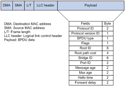
The payload of a configuration BPDU includes the following fields:
· Protocol ID—Fixed at 0x0000, which represents IEEE 802.1d.
· Protocol version ID—Spanning tree protocol version ID. The protocol version ID for STP is 0x00.
· BPDU type—Type of the BPDU. The value is 0x00 for a configuration BPDU.
· Flags—An 8-bit field indicates the purpose of the BPDU. The lowest bit is the Topology Change (TC) flag. The highest bit is the Topology Change Acknowledge (TCA) flag. All other bits are reserved.
· Root ID—Root bridge ID formed by the priority and MAC address of the root bridge.
· Root path cost—Cost of the path to the root bridge.
· Bridge ID—Designated bridge ID formed by the priority and MAC address of the designated bridge.
· Port ID—Designated port ID formed by the priority and global port number of the designated port.
· Message age—Age of the configuration BPDU while it propagates in the network.
· Max age—Maximum age of the configuration BPDU stored on the switch.
· Hello time—Configuration BPDU transmission interval.
· Forward delay—Delay for STP bridges to transit port state.
Devices use the root bridge ID, root path cost, designated bridge ID, designated port ID, message age, max age, hello time, and forward delay for spanning tree calculation.
TCN BPDUs
Devices use TCN BPDUs to announce changes in the network topology. Figure 2 shows the TCN BPDU format.
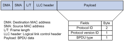
The payload of a TCN BPDU includes the following fields:
· Protocol ID—Fixed at 0x0000, which represents IEEE 802.1d.
· Protocol version ID—Spanning tree protocol version ID. The protocol version ID for STP is 0x00.
· BPDU type—Type of the BPDU. The value is 0x80 for a TCN BPDU.
A non-root bridge sends TCN BPDUs when one of the following events occurs on the bridge:
· A port transits to the forwarding state, and the bridge has a minimum of one designated port.
· A port transits from the forwarding or learning state to the blocking state.
The non-root bridge uses TCN BPDUs to notify the root bridge once the network topology changes. The root bridge then sets the TC flag in its configuration BPDU and propagates it to other bridges.
Basic concepts in STP
Root bridge
A tree network must have a root bridge. The entire network contains only one root bridge, and all the other bridges in the network are called leaf nodes. The root bridge is not permanent, but can change with changes of the network topology.
Upon initialization of a network, each device generates and periodically sends configuration BPDUs, with itself as the root bridge. After network convergence, only the root bridge generates and periodically sends configuration BPDUs. The other devices only forward the BPDUs.
Root port
Designated bridge and designated port
|
Classification |
Designated bridge |
Designated port |
|
For a device |
Device directly connected to the local device and responsible for forwarding BPDUs to the local device. |
Port through which the designated bridge forwards BPDUs to this device. |
|
For a LAN |
Device responsible for forwarding BPDUs to this LAN segment. |
Port through which the designated bridge forwards BPDUs to this LAN segment. |
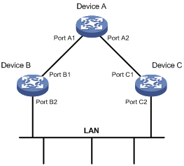
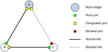
As shown in Figure 3, Device B and Device C are directly connected to a LAN.
If Device A forwards BPDUs to Device B through port A1, the designated bridge and designated port are as follows:
· The designated bridge for Device B is Device A.
· The designated port for Device B is port A1 on Device A.
If Device B forwards BPDUs to the LAN, the designated bridge and designated port are as follows:
· The designated bridge for the LAN is Device B.
· The designated port for the LAN is port B2 on Device B.
Figure 3 Designated bridges and designated ports
Port states
Table 1 lists the port states in STP.
|
State |
Receives/sends BPDUs |
Learns MAC addresses |
Forwards user data |
|
Disabled |
No |
No |
No |
|
Listening |
Yes |
No |
No |
|
Learning |
Yes |
Yes |
No |
|
Forwarding |
Yes |
Yes |
Yes |
|
Blocking |
Receive |
No |
No |
Path cost
Path cost is a reference value used for link selection in STP. To prune the network into a loop-free tree, STP calculates path costs to select the most robust links and block redundant links that are less robust.
Calculation process of the STP algorithm
In STP calculation, a device compares the priorities of the received configuration BPDUs from different ports, and elects the root bridge, root ports and designated ports. When the spanning tree calculation is completed, a tree-shape topology forms.
The spanning tree calculation process described in the following sections is an example of a simplified process.
Network initialization
Upon initialization of a device, each port generates a BPDU with the following contents:
· The port as the designated port.
· The device as the root bridge.
· 0 as the root path cost.
· The device ID as the designated bridge ID.
Root bridge selection
The root bridge can be selected in the following methods:
· Automatic election—Initially, each STP-enabled device on the network assumes itself to be the root bridge, with its own device ID as the root bridge ID. By exchanging configuration BPDUs, the devices compare their root bridge IDs to elect the device with the smallest root bridge ID as the root bridge.
· Manual assignment—You can configure a device as the root bridge or a secondary root bridge of a spanning tree.
¡ A spanning tree can have only one root bridge. If you configure multiple devices as the root bridge for a spanning tree, the device with the lowest MAC address is selected.
¡ You can configure one or multiple secondary root bridges for a spanning tree. When the root bridge fails or is shut down, a secondary root bridge can take over. If multiple secondary root bridges are configured, the one with the lowest MAC address is selected. However, if a new root bridge is configured, the secondary root bridge is not selected.
Root port and designated ports selection on the non-root bridges
|
Step |
Description |
|
1 |
A non-root-bridge device regards the port on which it received the optimum configuration BPDU as the root port. Table 2 describes how the optimum configuration BPDU is selected. |
|
2 |
Based on the configuration BPDU and the path cost of the root port, the device calculates a designated port configuration BPDU for each of the other ports. · The root bridge ID is replaced with that of the configuration BPDU of the root port. · The root path cost is replaced with that of the configuration BPDU of the root port plus the path cost of the root port. · The designated bridge ID is replaced with the ID of this device. · The designated port ID is replaced with the ID of this port. |
|
3 |
The device compares the calculated configuration BPDU with the configuration BPDU on the port whose port role will be determined. Then, the device acts depending on the result of the comparison: · If the calculated configuration BPDU is superior, the device performs the following operations: ¡ Considers this port as the designated port. ¡ Replaces the configuration BPDU on the port with the calculated configuration BPDU. ¡ Periodically sends the calculated configuration BPDU. · If the configuration BPDU on the port is superior, the device blocks this port without updating its configuration BPDU. The blocked port can receive BPDUs, but cannot send BPDUs or forward data traffic. |
When the network topology is stable, only the root port and designated ports forward user traffic. Other ports are all in the blocking state to receive BPDUs but not to forward BPDUs or user traffic.
Table 2 Selecting the optimum configuration BPDU
|
Step |
Actions |
|
1 |
Upon receiving a configuration BPDU on a port, the device compares the priority of the received configuration BPDU with that of the configuration BPDU generated by the port. · If the former priority is lower, the device discards the received configuration BPDU and keeps the configuration BPDU the port generated. · If the former priority is higher, the device replaces the content of the configuration BPDU generated by the port with the content of the received configuration BPDU. |
|
2 |
The device compares the configuration BPDUs of all the ports and chooses the optimum configuration BPDU. |
The following are the principles of configuration BPDU comparison:
1. The configuration BPDU with the lowest root bridge ID has the highest priority.
2. If configuration BPDUs have the same root bridge ID, their root path costs are compared. For example, the root path cost in a configuration BPDU plus the path cost of a receiving port is S. The configuration BPDU with the smallest S value has the highest priority.
3. If all configuration BPDUs have the same root bridge ID and S value, the following attributes are compared in sequence:
a. Designated bridge IDs.
b. Designated port IDs.
c. IDs of the receiving ports.
The configuration BPDU that contains a smaller designated bridge ID, designated port ID, or receiving port ID is selected.
A tree-shape topology forms when the root bridge, root ports, and designated ports are selected.
Example of STP calculation
Figure 4 provides an example showing how the STP algorithm works.
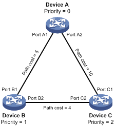
As shown in Figure 4, the priority values of Device A, Device B, and Device C are 0, 1, and 2, respectively. The path costs of links among the three devices are 5, 10, and 4.
Device state initialization
In Table 3, each configuration BPDU contains the following fields: root bridge ID, root path cost, designated bridge ID, and designated port ID.
Table 3 Initial state of each device
|
Device |
Port name |
Configuration BPDU on the port |
|
Device A |
Port A1 |
{0, 0, 0, Port A1} |
|
Port A2 |
{0, 0, 0, Port A2} |
|
|
Device B |
Port B1 |
{1, 0, 1, Port B1} |
|
Port B2 |
{1, 0, 1, Port B2} |
|
|
Device C |
Port C1 |
{2, 0, 2, Port C1} |
|
Port C2 |
{2, 0, 2, Port C2} |
Configuration BPDUs comparison on each device
In Table 4, each configuration BPDU contains the following fields: root bridge ID, root path cost, designated bridge ID, and designated port ID.
Table 4 Comparison process and result on each device
|
Device |
Comparison process |
Configuration BPDU on ports after comparison |
|
Device A |
Port A1 performs the following operations: 1. Receives the configuration BPDU of Port B1 {1, 0, 1, Port B1}. 2. Determines that its existing configuration BPDU {0, 0, 0, Port A1} is superior to the received configuration BPDU. 3. Discards the received one. Port A2 performs the following operations: 1. Receives the configuration BPDU of Port C1 {2, 0, 2, Port C1}. 2. Determines that its existing configuration BPDU {0, 0, 0, Port A2} is superior to the received configuration BPDU. 3. Discards the received one. Device A determines that it is both the root bridge and designated bridge in the configuration BPDUs of all its ports. It considers itself as the root bridge. It does not change the configuration BPDU of any port and starts to periodically send configuration BPDUs. |
· Port A1: {0, 0, 0, Port A1} · Port A2: {0, 0, 0, Port A2} |
|
Device B |
Port B1 performs the following operations: 1. Receives the configuration BPDU of Port A1 {0, 0, 0, Port A1}. 2. Determines that the received configuration BPDU is superior to its existing configuration BPDU {1, 0, 1, Port B1}. 3. Updates its configuration BPDU. Port B2 performs the following operations: 1. Receives the configuration BPDU of Port C2 {2, 0, 2, Port C2}. 2. Determines that its existing configuration BPDU {1, 0, 1, Port B2} is superior to the received configuration BPDU. 3. Discards the received BPDU. |
· Port B1: {0, 0, 0, Port A1} · Port B2: {1, 0, 1, Port B2} |
|
Device B performs the following operations: 1. Compares the configuration BPDUs of all its ports. 2. Decides that the configuration BPDU of Port B1 is the optimum. 3. Selects Port B1 as the root port with the configuration BPDU unchanged. Based on the configuration BPDU and path cost of the root port, Device B calculates a designated port configuration BPDU for Port B2 {0, 5, 1, Port B2}. Device B compares it with the existing configuration BPDU of Port B2 {1, 0, 1, Port B2}. Device B determines that the calculated one is superior, and determines that Port B2 is the designated port. It replaces the configuration BPDU on Port B2 with the calculated one, and periodically sends the calculated configuration BPDU. |
· Root port (Port B1): {0, 0, 0, Port A1} · Designated port (Port B2): {0, 5, 1, Port B2} |
|
|
Device C |
Port C1 performs the following operations: 1. Receives the configuration BPDU of Port A2 {0, 0, 0, Port A2}. 2. Determines that the received configuration BPDU is superior to its existing configuration BPDU {2, 0, 2, Port C1}. 3. Updates its configuration BPDU. Port C2 performs the following operations: 1. Receives the original configuration BPDU of Port B2 {1, 0, 1, Port B2}. 2. Determines that the received configuration BPDU is superior to the existing configuration BPDU {2, 0, 2, Port C2}. 3. Updates its configuration BPDU. |
· Port C1: {0, 0, 0, Port A2} · Port C2: {1, 0, 1, Port B2} |
|
Device C performs the following operations: 1. Compares the configuration BPDUs of all its ports. 2. Decides that the configuration BPDU of Port C1 is the optimum. 3. Selects Port C1 as the root port with the configuration BPDU unchanged. Based on the configuration BPDU and path cost of the root port, Device C calculates the configuration BPDU of Port C2 {0, 10, 2, Port C2}. Device C compares it with the existing configuration BPDU of Port C2 {1, 0, 1, Port B2}. Device C determines that the calculated configuration BPDU is superior to the existing one, selects Port C2 as the designated port, and replaces the configuration BPDU of Port C2 with the calculated one. |
· Root port (Port C1): {0, 0, 0, Port A2} · Designated port (Port C2): {0, 10, 2, Port C2} |
|
|
Port C2 performs the following operations: 1. Receives the updated configuration BPDU of Port B2 {0, 5, 1, Port B2}. 2. Determines that the received configuration BPDU is superior to its existing configuration BPDU {0, 10, 2, Port C2}. 3. Updates its configuration BPDU. Port C1 performs the following operations: 1. Receives a periodic configuration BPDU {0, 0, 0, Port A2} from Port A2. 2. Determines that it is the same as the existing configuration BPDU. 3. Discards the received BPDU. |
· Port C1: {0, 0, 0, Port A2} · Port C2: {0, 5, 1, Port B2} |
|
|
Device C determines that the root path cost of Port C1 is larger than that of Port C2. The root path cost of Port C1 is 10, root path cost of the received configuration BPDU (0) plus path cost of Port C1 (10). The root path cost of Port C2 is 9, root path cost of the received configuration BPDU (5) plus path cost of Port C2 (4). Device C determines that the configuration BPDU of Port C2 is the optimum, and selects Port C2 as the root port with the configuration BPDU unchanged. Based on the configuration BPDU and path cost of the root port, Device C performs the following operations: 1. Calculates a designated port configuration BPDU for Port C1 {0, 9, 2, Port C1}. 2. Compares it with the existing configuration BPDU of Port C1 {0, 0, 0, Port A2}. 3. Determines that the existing configuration BPDU is superior to the calculated one and blocks Port C1 with the configuration BPDU unchanged. Port C1 does not forward data until a new event triggers a spanning tree calculation process: for example, the link between Device B and Device C is down. |
· Blocked port (Port C1): {0, 0, 0, Port A2} · Root port (Port C2): {0, 5, 1, Port B2} |
Final calculated spanning tree
After the comparison processes described in Table 4, a spanning tree with Device A as the root bridge is established, as shown in Figure 5.
Figure 5 The final calculated spanning tree
The configuration BPDU forwarding mechanism of STP
The configuration BPDUs of STP are forwarded according to these guidelines:
· Upon network initiation, every device regards itself as the root bridge and generates configuration BPDUs with itself as the root. Then it sends the configuration BPDUs at a regular hello interval.
· If the root port receives a configuration BPDU superior to the configuration BPDU of the port, the device performs the following operations:
¡ Increases the message age carried in the configuration BPDU.
¡ Starts a timer to time the configuration BPDU.
¡ Sends this configuration BPDU through the designated port.
· If a designated port receives a configuration BPDU with a lower priority than its configuration BPDU, the port immediately responds with its configuration BPDU.
· If a path fails, the root port on this path no longer receives new configuration BPDUs and the old configuration BPDUs will be discarded due to timeout. The device generates a configuration BPDU with itself as the root and sends the BPDUs and TCN BPDUs. This triggers a new spanning tree calculation process to establish a new path to restore the network connectivity.
However, the newly calculated configuration BPDU cannot be propagated throughout the network immediately. As a result, the old root ports and designated ports that have not detected the topology change continue forwarding data along the old path. If the new root ports and designated ports begin to forward data as soon as they are elected, a temporary loop might occur.
STP timers
The most important timing parameters in STP calculation are forward delay, hello time, and max age.
· Forward delay
Forward delay is the delay time for port state transition. By default, the forward delay is 15 seconds.
A path failure can cause spanning tree re-calculation to adapt the spanning tree structure to the change. However, the resulting new configuration BPDU cannot propagate throughout the network immediately. If the newly elected root ports and designated ports start to forward data immediately, a temporary loop will likely occur.
The newly elected root ports or designated ports must go through the listening and learning states before they transit to the forwarding state. This requires twice the forward delay time and allows the new configuration BPDU to propagate throughout the network.
· Hello time
The device sends configuration BPDUs at the hello time interval to the neighboring devices to ensure that the paths are fault-free. By default, the hello time is 2 seconds. If the device does not receive configuration BPDUs within the timeout period, it recalculates the spanning tree. The formula for calculating the timeout period is timeout period = timeout factor × 3 × hello time.
· Max age
The device uses the max age to determine whether a stored configuration BPDU has expired and discards it if the max age is exceeded. By default, the max age is 20 seconds. In the CIST of an MSTP network, the device uses the max age timer to determine whether a configuration BPDU received by a port has expired. If it is expired, a new spanning tree calculation process starts. The max age timer does not take effect on MSTIs.
If a port does not receive any configuration BPDUs within the timeout period, the port transits to the listening state. The device will recalculate the spanning tree. It takes the port 50 seconds to transit back to the forwarding state. This period includes 20 seconds for the max age, 15 seconds for the listening state, and 15 seconds for the learning state.
To ensure a fast topology convergence, make sure the timer settings meet the following formulas:
· 2 × (forward delay – 1 second) ≥ max age
· Max age ≥ 2 × (hello time + 1 second)
About RSTP
RSTP achieves rapid network convergence by allowing a newly elected root port or designated port to enter the forwarding state much faster than STP.
RSTP protocol frames
An RSTP BPDU uses the same format as an STP BPDU except that a Version1 length field is added to the payload of RSTP BPDUs. The differences between an RSTP BPDU and an STP BPDU are as follows:
· Protocol version ID—The value is 0x02 for RSTP.
· BPDU type—The value is 0x02 for RSTP BPDUs.
· Flags—All 8 bits are used.
· Version1 length—The value is 0x00, which means no version 1 protocol information is present.
RSTP does not use TCN BPDUs to advertise topology changes. RSTP floods BPDUs with the TC flag set in the network to advertise topology changes.
Basic concepts in RSTP
Port roles
In addition to root port and designated port, RSTP also uses the following port roles:
· Alternate port—Acts as the backup port for a root port. When the root port is blocked, the alternate port takes over.
· Backup port—Acts as the backup port of a designated port. When the designated port is invalid, the backup port becomes the new designated port. A loop occurs when two ports of the same spanning tree device are connected, so the device blocks one of the ports. The blocked port is the backup port.
· Edge port—Directly connects to a user host rather than a network device or network segment.
Port states
RSTP uses the discarding state to replace the disabled, blocking, and listening states in STP. Table 5 shows the differences between the port states in RSTP and STP.
Table 5 Port state differences between RSTP and STP
|
STP port state |
RSTP port state |
Sends BPDU |
Learns MAC addresses |
Forwards user data |
|
Disabled |
Discarding |
No |
No |
No |
|
Blocking |
Discarding |
No |
No |
No |
|
Listening |
Discarding |
Yes |
No |
No |
|
Learning |
Learning |
Yes |
Yes |
No |
|
Forwarding |
Forwarding |
Yes |
Yes |
Yes |
How RSTP works
During RSTP calculation, the following events occur:
· If a port in discarding state becomes an alternate port, it retains its state.
· If a port in discarding state is elected as the root port or designated port, it enters the learning state after the forward delay. The port learns MAC addresses, and enters the forwarding state after another forward delay.
¡ A newly elected RSTP root port rapidly enters the forwarding state if the following requirements are met:
- The old root port on the device has stopped forwarding data.
- The upstream designated port has started forwarding data.
¡ A newly elected RSTP designated port rapidly enters the forwarding state if one of the following requirements is met:
- The designated port is configured as an edge port which directly connects to a user terminal.
- The designated port connects to a point-to-point link and receives a handshake response from the directly connected device.
RSTP BPDU processing
In RSTP, a non-root bridge actively sends RSTP BPDUs at the hello time through designated ports without waiting for the root bridge to send RSTP BPDUs. This enables RSTP to quickly detect link failures. If a device fails to receive any RSTP BPDUs on a port within triple the hello time, the device considers that a link failure has occurred. After the stored configuration BPDU expires, the device floods RSTP BPDUs with the TC flag set to initiate a new RSTP calculation.
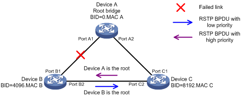
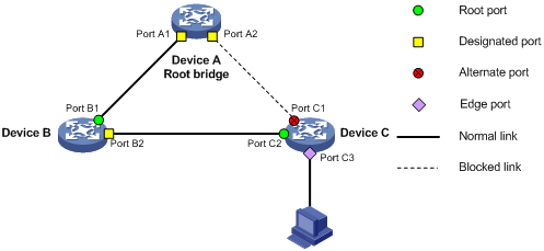
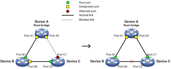
In RSTP, a port in blocking state can immediately respond to an RSTP BPDU with a lower priority than its own BPDU.
As shown in Figure 6, Device A is the root bridge. The priority of Device B is higher than the priority of Device C. Port C2 on Device C is blocked.
When the link between Device A and Device B fails, the following events occur:
1. Device B sends an RSTP BPDU with itself as the root bridge to Device C.
2. Device C compares the RSTP BPDU with its own BPDU.
3. Because the RSTP BPDU from Device B has a lower priority, Device C sends its own BPDU to Device B.
4. Device B considers that Port B2 is the root port and stops sending RSTP BPDUs to Device C.
Figure 6 BPDU processing in RSTP
About PVST
In an STP- or RSTP-enabled LAN, all bridges share one spanning tree. Traffic from all VLANs is forwarded along the spanning tree, and ports cannot be blocked on a per-VLAN basis to prune loops.
PVST allows every VLAN to have its own spanning tree, which increases usage of links and bandwidth. Because each VLAN runs RSTP independently, a spanning tree only serves its VLAN.
A PVST-enabled H3C device can communicate with a third-party device that is running Rapid PVST or PVST. The PVST-enabled H3C device supports fast network convergence like RSTP when connected to PVST-enabled H3C devices or third-party devices enabled with Rapid PVST.
PVST protocol frames
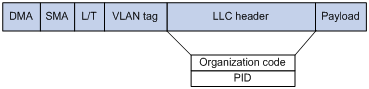
As shown in Figure 7, a PVST BPDU uses the same format as an RSTP BPDU except the following differences:
· The destination MAC address of a PVST BPDU is 01-00-0c-cc-cc-cd, which is a private MAC address.
· Each PVST BPDU carries a VLAN tag. The VLAN tag identifies the VLAN to which the PVST BPDU belongs.
· The organization code and PID fields are added to the LLC header of the PVST BPDU.
A port's link type determines the type of BPDUs the port sends.
· An access port sends RSTP BPDUs.
· A trunk or hybrid port sends RSTP BPDUs in the default VLAN and sends PVST BPDUs in other VLANs.
How PVST works
PVST implements per-VLAN spanning tree calculation by mapping each VLAN to an MSTI. In PVST, each VLAN runs RSTP independently to maintain its own spanning tree without affecting the spanning trees of other VLANs. In this way, loops in each VLAN are eliminated and traffic of different VLANs is load shared over links. PVST uses RSTP BPDUs in the default VLAN and PVST BPDUs in other VLANs for spanning tree calculation.
PVST uses the same port roles and port states as RSTP for rapid transition. For more information, see "Basic concepts in RSTP."
About MSTP
MSTP features
Developed based on IEEE 802.1s, MSTP overcomes the limitations of STP, RSTP, and PVST. In addition to supporting rapid network convergence, it allows data flows of different VLANs to be forwarded along separate paths. This provides a better load sharing mechanism for redundant links.
MSTP provides the following features:
· MSTP divides a switched network into multiple regions, each of which contains multiple spanning trees that are independent of one another.
· MSTP supports mapping VLANs to spanning tree instances by means of a VLAN-to-instance mapping table. MSTP can reduce communication overheads and resource usage by mapping multiple VLANs to one instance.
· MSTP prunes a loop network into a loop-free tree, which avoids proliferation and endless cycling of frames in a loop network. In addition, it supports load balancing of VLAN data by providing multiple redundant paths for data forwarding.
· MSTP is compatible with STP and RSTP, and partially compatible with PVST.
MSTP protocol frames
Figure 8 shows the format of an MSTP BPDU.
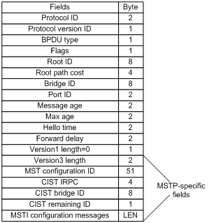
The first 13 fields of an MSTP BPDU are the same as an RSTP BPDU. The other six fields are unique to MSTP.
· Protocol version ID—The value is 0x03 for MSTP.
· BPDU type—The value is 0x02 for RSTP/MSTP BPDUs.
· Root ID—ID of the common root bridge.
· Root path cost—CIST external path cost.
· Bridge ID—ID of the regional root for the IST or an MSTI.
· Port ID—ID of the designated port in the CIST.
· Version3 length—Length of the MSTP-specific fields. Devices use this field for verification upon receiving an MSTP BPDU.
· MST configuration ID—Includes the format selector, configuration name, revision level, and configuration digest. The value for format selector is fixed at 0x00. The other parameters are used to identify the MST region for the originating bridge.
· CIST IRPC—Internal root path cost (IRPC) from the originating bridge to the root of the MST region.
· CIST bridge ID—ID of the bridge that sends the MSTP BPDU.
· CIST remaining ID—Remaining hop count. This field limits the scale of the MST region. The regional root sends a BPDU with the remaining hop count set to the maximum value. Each device that receives the BPDU decrements the hop count by one. When the hop count reaches zero, the BPDU is discarded. Devices beyond the maximum hops of the MST region cannot participate in spanning tree calculation. The default remaining hop count is 20.
· MSTI configuration messages—Contains MSTI configuration messages. Each MSTI configuration message is 16 bytes. This field can contain 0 to 64 MSTI configuration messages. The number of the MSTI configuration messages is determined by the number of MSTIs in the MST region.
Basic concepts in MSTP
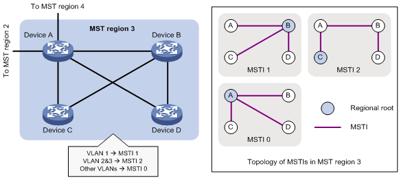
Figure 9 shows a switched network that contains four MST regions, each MST region containing four MSTP devices. Figure 10 shows the networking topology of MST region 3.
Figure 9 Basic concepts in MSTP
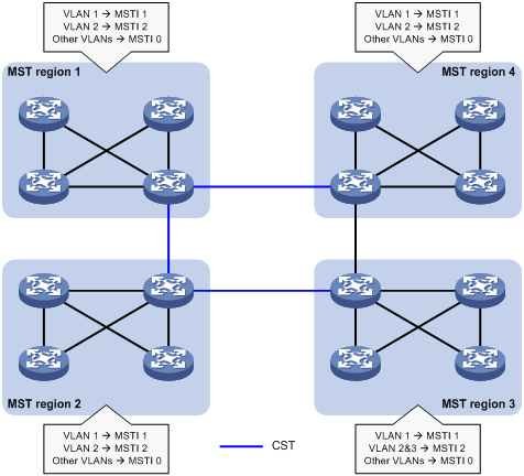
Figure 10 Network diagram and topology of MST region 3
MST region
A multiple spanning tree region (MST region) consists of multiple devices in a switched network and the network segments among them. All these devices have the following characteristics:
· A spanning tree protocol enabled
· Same region name
· Same VLAN-to-instance mapping configuration
· Same MSTP revision level
· Physically linked together
Multiple MST regions can exist in a switched network. You can assign multiple devices to the same MST region, as shown in Figure 9.
· The switched network contains four MST regions, MST region 1 through MST region 4.
· All devices in each MST region have the same MST region configuration.
MSTI
MSTP can generate multiple independent spanning trees in an MST region, and each spanning tree is mapped to the specific VLANs. Each spanning tree is referred to as a multiple spanning tree instance (MSTI).
In Figure 10, MST region 3 contains three MSTIs, MSTI 1, MSTI 2, and MSTI 0.
VLAN-to-instance mapping table
As an attribute of an MST region, the VLAN-to-instance mapping table describes the mapping relationships between VLANs and MSTIs.
In Figure 10, the VLAN-to-instance mapping table of MST region 3 is as follows:
· VLAN 1 to MSTI 1.
· VLAN 2 and VLAN 3 to MSTI 2.
· Other VLANs to MSTI 0.
MSTP achieves load balancing by means of the VLAN-to-instance mapping table.
CST
The common spanning tree (CST) is a single spanning tree that connects all MST regions in a switched network. If you regard each MST region as a device, the CST is a spanning tree calculated by these devices through STP or RSTP.
The blue lines in Figure 9 represent the CST.
IST
An internal spanning tree (IST) is a spanning tree that runs in an MST region. It is also called MSTI 0, a special MSTI to which all VLANs are mapped by default.
In Figure 9, MSTI 0 is the IST in MST region 3.
CIST
The common and internal spanning tree (CIST) is a single spanning tree that connects all devices in a switched network. It consists of the ISTs in all MST regions and the CST.
In Figure 9, the ISTs (MSTI 0) in all MST regions plus the inter-region CST constitute the CIST of the entire network.
Regional root
The root bridge of the IST or an MSTI within an MST region is the regional root of the IST or MSTI. Based on the topology, different spanning trees in an MST region might have different regional roots, as shown in MST region 3 in Figure 10.
· The regional root of MSTI 1 is Device B.
· The regional root of MSTI 2 is Device C.
· The regional root of MSTI 0 (also known as the IST) is Device A.
Common root bridge
The common root bridge is the root bridge of the CIST.
In Figure 9, the common root bridge is a device in MST region 1.
Port roles
A port can play different roles in different MSTIs. As shown in Figure 11, an MST region contains Device A, Device B, Device C, and Device D. Port A1 and port A2 of Device A connect to the common root bridge. Port B2 and Port B3 of Device B form a loop. Port C3 and Port C4 of Device C connect to other MST regions. Port D3 of Device D directly connects to a host.
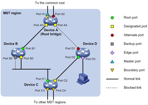
MSTP calculation involves the following port roles:
· Root port—Forwards data for a non-root bridge to the root bridge. The root bridge does not have any root port.
· Designated port—Forwards data to the downstream network segment or device.
· Alternate port—Acts as the backup port for a root port or master port. When the root port or master port is blocked, the alternate port takes over.
· Backup port—Acts as the backup port of a designated port. When the designated port is invalid, the backup port becomes the new designated port. A loop occurs when two ports of the same spanning tree device are connected, so the device blocks one of the ports. The blocked port acts as the backup.
· Edge port—Directly connects to a user host rather than a network device or network segment.
· Master port—Acts as a port on the shortest path from the local MST region to the common root bridge. The master port is not always located on the regional root. It is a root port on the IST or CIST and still a master port on the other MSTIs.
· Boundary port—Connects an MST region to another MST region or to an STP/RSTP-running device. In MSTP calculation, a boundary port's role on an MSTI is consistent with its role on the CIST. However, that is not true with master ports. A master port on MSTIs is a root port on the CIST.
Port states
In MSTP, a port can be in one of the following states:
· Forwarding—The port receives and sends BPDUs, learns MAC addresses, and forwards user traffic.
· Learning—The port receives and sends BPDUs, learns MAC addresses, but does not forward user traffic. Learning is an intermediate port state.
· Discarding—The port receives and sends BPDUs, but does not learn MAC addresses or forward user traffic.
|
|
NOTE: When in different MSTIs, a port can be in different states. |
A port state is not exclusively associated with a port role. Table 6 lists the port states that each port role supports. (A check mark [√] indicates that the port supports this state, while a dash [—] indicates that the port does not support this state.)
Table 6 Port states that different port roles support
|
Port role (right) Port state (below) |
Root port/master port |
Designated port |
Alternate port |
Backup port |
|
Forwarding |
√ |
√ |
— |
— |
|
Learning |
√ |
√ |
— |
— |
|
Discarding |
√ |
√ |
√ |
√ |
How MSTP works
MSTP divides an entire Layer 2 network into multiple MST regions, which are connected by a calculated CST. Inside an MST region, multiple spanning trees, called MSTIs, are calculated. Among these MSTIs, MSTI 0 is the IST.
Like STP, MSTP uses configuration BPDUs to calculate spanning trees. An important difference is that an MSTP BPDU carries the MSTP configuration of the bridge from which the BPDU is sent.
CIST calculation
During the CIST calculation, the following process takes place:
· The device with the highest priority is elected as the root bridge of the CIST.
· MSTP generates an IST within each MST region through calculation.
· MSTP regards each MST region as a single device and generates a CST among these MST regions through calculation.
The CST and ISTs constitute the CIST of the entire network.
MSTI calculation
Within an MST region, MSTP generates different MSTIs for different VLANs based on the VLAN-to-instance mappings. For each spanning tree, MSTP performs a separate calculation process similar to spanning tree calculation in STP. For more information, see "Calculation process of the STP algorithm."
In MSTP, a VLAN frame is forwarded along the following paths:
· Within an MST region, the frame is forwarded along the corresponding MSTI.
· Between two MST regions, the frame is forwarded along the CST.
MSTP implementation on devices
MSTP is compatible with STP and RSTP. Devices that are running MSTP and that are used for spanning tree calculation can identify STP and RSTP protocol frames.
In addition to basic MSTP features, the following features are provided for ease of management:
· Root bridge hold.
· Root bridge backup.
· Root guard.
· BPDU guard.
· TC-BPDU guard.
· Port role restriction.
· TC-BPDU transmission restriction.
· Support for hot swapping of interface cards and active/standby changeover.
Rapid transition mechanism
In STP, a port must wait twice the forward delay (30 seconds by default) before it transits from the blocking state to the forwarding state. The forward delay is related to the hello time and network diameter. If the forward delay is too short, loops might occur. This affects the stability of the network.
RSTP, PVST, and MSTP all use the rapid transition mechanism to speed up port state transition for edge ports, root ports, and designated ports. The rapid transition mechanism for designated ports is also known as the proposal/agreement (P/A)_transition.
Edge port rapid transition
As shown in Figure 12, Port C3 is an edge port connected to a host. When a network topology change occurs, the port can immediately transit from the blocking state to the forwarding state because no loop will be caused.
Because a device cannot determine whether a port is directly connected to a terminal, you must manually configure the port as an edge port.
Figure 12 Edge port rapid transition
Root port rapid transition
When a root port is blocked, the bridge will elect the alternate port with the highest priority as the new root port. If the new root port's peer is in the forwarding state, the new root port immediately transits to the forwarding state.
As shown in Figure 13, Port C2 on Device C is a root port and Port C1 is an alternate port. When Port C2 transits to the blocking state, Port C1 is elected as the root port and immediately transits to the forwarding state.
Figure 13 Root port rapid transition
P/A transition
The P/A transition enables a designated port to rapidly transit to the forwarding state after a handshake with its peer. The P/A transition applies only to point-to-point links.
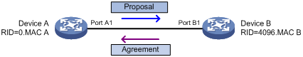
P/A transition for RSTP and PVST
In RSTP or PVST, the ports on a new link or recovered link are designated ports in blocking state. When one of the designated ports transits to the discarding or learning state, it sets the proposal flag in its BPDU. Its peer bridge receives the BPDU and determines whether the receiving port is the root port. If it is the root port, the bridge blocks the other ports except edge ports. The bridge then replies an agreement BPDU to the designated port. The designated port immediately transits to the forwarding state upon receiving the agreement BPDU. If the designated port does not receive the agreement BPDU, it waits for twice the forward delay to transit to the forwarding state.
As shown in Figure 14, the P/A transition operates as follows:
1. Device A sends a proposal BPDU to Device B through Port A1.
2. Device B receives the proposal BPDU on Port B2. Port B2 is elected as the root port.
3. Device B blocks its designated port Port B1 and alternate port Port B3 to eliminate loops.
4. The root port Port B2 transits to the forwarding state and sends an agreement BPDU to Device A.
5. The designated port Port A1 on Device A immediately transits to the forwarding state after receiving the agreement BPDU.
Figure 14 P/A transition for RSTP and PVST
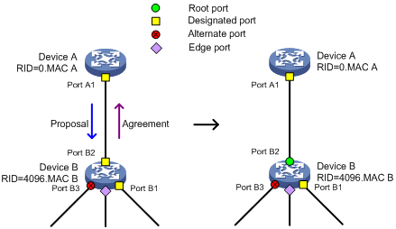
P/A transition for MSTP
In MSTP, an upstream bridge sets both the proposal and agreement flags in its BPDU. If a downstream bridge receives the BPDU and its receiving port is elected as the root port, the bridge blocks all the other ports except edge ports. The downstream bridge then replies an agreement BPDU to the upstream bridge. The upstream port immediately transits to the forwarding state upon receiving the agreement BPDU. If the upstream port does not receive the agreement BPDU, it waits for twice the forward delay to transit to the forwarding state.
As shown in Figure 15, the P/A transition operates as follows:
1. Device A sets the proposal and agreement flags in its BPDU and sends it to Device B through Port A1.
2. Device B receives the BPDU. Port B1 of Device B is elected as the root port.
3. Device B then blocks all its ports except the edge ports.
4. The root port Port B1 of Device B transits to the forwarding state and sends an agreement BPDU to Device A.
5. Port A1 of Device A immediately transits to the forwarding state upon receiving the agreement BPDU.
Figure 15 P/A transition for MSTP
Protocols and standards
MSTP is documented in the following protocols and standards:
· IEEE 802.1d, Media Access Control (MAC) Bridges
· IEEE 802.1w, Part 3: Media Access Control (MAC) Bridges—Amendment 2: Rapid Reconfiguration
· IEEE 802.1s, Virtual Bridged Local Area Networks—Amendment 3: Multiple Spanning Trees
· IEEE 802.1Q-REV/D1.3, Media Access Control (MAC) Bridges and Virtual Bridged Local Area Networks —Clause 13: Spanning tree Protocols
Configuring spanning tree protocols
Restrictions and guidelines: spanning tree protocol configuration
Restrictions: Compatibility with other features
· When the spanning tree protocol is enabled for a DR system, make sure the DR member devices have the same spanning tree configuration, including:
¡ Global spanning tree configuration.
¡ Spanning tree configuration on the IPP.
¡ Spanning tree configuration on DR interfaces.
Violation of this rule might cause network flapping. IPPs in the DR system do not participate in spanning tree calculation. To view the spanning tree information of DR interfaces, use related display commands on the primary DR device. For more information about the DR system, DR interfaces, and IPPs, see "Configuring DRNI."
· If both MVRP and a spanning tree protocol are enabled on a device, MVRP packets are forwarded along MSTIs. To advertise a specific VLAN within the network through MVRP, make sure this VLAN is mapped to an MSTI when you configure the VLAN-to-instance mapping table. For more information about MVRP, see "Configuring MVRP."
· The spanning tree configurations are mutually exclusive with any of the following features on a port: service loopback group, RRPP, and Smart Link.
Restrictions: Interface configuration
· Some spanning tree features are supported in Layer 2 Ethernet interface view, Layer 2 aggregate interface view, and Layer 2 RPR logical interface view. Unless otherwise stated, these views are collectively referred to as interface view in this document. BPDU drop can be configured only in Layer 2 Ethernet interface view.
· Configurations made in system view take effect globally. Configurations made in Layer 2 Ethernet interface view take effect only on the interface. Configurations made in Layer 2 aggregate interface view take effect only on the aggregate interface. Configurations made on an aggregation member port can take effect only after the port is removed from the aggregation group.
· After you enable a spanning tree protocol on a Layer 2 aggregate interface, the system performs spanning tree calculation on the Layer 2 aggregate interface. It does not perform spanning tree calculation on the aggregation member ports. The spanning tree protocol enable state and forwarding state of each selected member port are consistent with those of the corresponding Layer 2 aggregate interface.
· The member ports of an aggregation group do not participate in spanning tree calculation. However, the ports still reserve their spanning tree configurations for participating in spanning tree calculation after leaving the aggregation group.
Spanning tree protocol tasks at a glance
STP tasks at a glance
Configuring the root bridge
To configure the root bridge in STP mode, perform the following tasks:
1. Setting the spanning tree mode
Set the spanning tree mode to STP.
2. (Optional.) Configuring the root bridge or a secondary root bridge
3. (Optional.) Configuring the device priority
4. (Optional.) Configuring parameters that affects STP topology convergence
¡ Configuring the network diameter of a switched network
¡ Setting spanning tree timers
¡ Setting the timeout factor
¡ Configuring the BPDU transmission rate
5. (Optional.) Enabling outputting port state transition information
6. Enabling the spanning tree feature
7. (Optional.) Configuring advanced spanning tree features
¡ Configuring protection features
¡ Disabling the device from reactivating edge ports shut down by BPDU guard
¡ Enabling BPDU transparent transmission on a port
¡ Enabling SNMP notifications for new-root election and topology change events
Configuring the leaf nodes
To configure the leaf nodes in STP mode, perform the following tasks:
1. Setting the spanning tree mode
Set the spanning tree mode to STP.
2. (Optional.) Configuring the device priority
3. (Optional.) Configuring parameters that affects STP topology convergence
¡ Setting the timeout factor
¡ Configuring the BPDU transmission rate
¡ Configuring path costs of ports
¡ Configuring the port priority
4. (Optional.) Enabling outputting port state transition information
5. Enabling the spanning tree feature
6. (Optional.) Configuring advanced spanning tree features
¡ Configuring protection features
¡ Disabling the device from reactivating edge ports shut down by BPDU guard
¡ Enabling BPDU transparent transmission on a port
¡ Enabling SNMP notifications for new-root election and topology change events
RSTP tasks at a glance
Configuring the root bridge
To configure the root bridge in RSTP mode, perform the following tasks:
1. Setting the spanning tree mode
Set the spanning tree mode to RSTP.
2. (Optional.) Configuring the root bridge or a secondary root bridge
3. (Optional.) Configuring the device priority
4. (Optional.) Configuring parameters that affects RSTP topology convergence
¡ Configuring the network diameter of a switched network
¡ Setting spanning tree timers
¡ Setting the timeout factor
¡ Configuring the BPDU transmission rate
¡ Configuring edge ports
¡ Configuring the port link type
5. (Optional.) Enabling outputting port state transition information
6. Enabling the spanning tree feature
7. (Optional.) Configuring advanced spanning tree features
¡ Performing mCheck
¡ Configuring protection features
¡ Disabling the device from reactivating edge ports shut down by BPDU guard
¡ Enabling BPDU transparent transmission on a port
¡ Enabling SNMP notifications for new-root election and topology change events
Configuring the leaf nodes
To configure the leaf nodes in RSTP mode, perform the following tasks:
1. Setting the spanning tree mode
Set the spanning tree mode to RSTP.
2. (Optional.) Configuring the device priority
3. (Optional.) Configuring parameters that affects RSTP topology convergence
¡ Setting the timeout factor
¡ Configuring the BPDU transmission rate
¡ Configuring edge ports
¡ Configuring path costs of ports
¡ Configuring the port priority
¡ Configuring the port link type
4. (Optional.) Enabling outputting port state transition information
5. Enabling the spanning tree feature
6. (Optional.) Configuring advanced spanning tree features
¡ Performing mCheck
¡ Configuring protection features
¡ Disabling the device from reactivating edge ports shut down by BPDU guard
¡ Enabling BPDU transparent transmission on a port
¡ Enabling SNMP notifications for new-root election and topology change events
PVST tasks at a glance
Configuring the root bridge
To configure the root bridge in PVST mode, perform the following tasks:
1. Setting the spanning tree mode
Set the spanning tree mode to PVST.
2. (Optional.) Configuring the root bridge or a secondary root bridge
3. (Optional.) Configuring the device priority
4. (Optional.) Configuring parameters that affects PVST topology convergence
¡ Configuring the network diameter of a switched network
¡ Setting spanning tree timers
¡ Setting the timeout factor
¡ Configuring the BPDU transmission rate
¡ Configuring edge ports
¡ Configuring the port link type
5. (Optional.) Enabling outputting port state transition information
6. Enabling the spanning tree feature
7. (Optional.) Configuring advanced spanning tree features
¡ Performing mCheck
¡ Disabling inconsistent PVID protection
¡ Configuring protection features
¡ Enabling the device to log events of detecting or receiving TC BPDUs
¡ Disabling the device from reactivating edge ports shut down by BPDU guard
¡ Enabling BPDU transparent transmission on a port
¡ Enabling SNMP notifications for new-root election and topology change events
Configuring the leaf nodes
To configure the leaf nodes in PVST mode, perform the following tasks:
1. Setting the spanning tree mode
Set the spanning tree mode to PVST.
2. (Optional.) Configuring the device priority
3. (Optional.) Configuring parameters that affects PVST topology convergence
¡ Setting the timeout factor
¡ Configuring the BPDU transmission rate
¡ Configuring edge ports
¡ Configuring path costs of ports
¡ Configuring the port priority
¡ Configuring the port link type
4. (Optional.) Enabling outputting port state transition information
5. Enabling the spanning tree feature
6. (Optional.) Configuring advanced spanning tree features
¡ Performing mCheck
¡ Disabling inconsistent PVID protection
¡ Configuring protection features
¡ Enabling the device to log events of detecting or receiving TC BPDUs
¡ Disabling the device from reactivating edge ports shut down by BPDU guard
¡ Enabling BPDU transparent transmission on a port
¡ Enabling SNMP notifications for new-root election and topology change events
MSTP tasks at a glance
Configuring the root bridge
To configure the root bridge in MSTP mode, perform the following tasks:
1. Setting the spanning tree mode
Set the spanning tree mode to MSTP.
2. Configuring an MST region
3. (Optional.) Configuring the root bridge or a secondary root bridge
4. (Optional.) Configuring the device priority
5. (Optional.) Configuring parameters that affects MSTP topology convergence
¡ Configuring the maximum hops of an MST region
¡ Configuring the network diameter of a switched network
¡ Setting spanning tree timers
¡ Setting the timeout factor
¡ Configuring the BPDU transmission rate
¡ Configuring edge ports
¡ Configuring the port link type
6. (Optional.) Configuring the mode a port uses to recognize and send MSTP frames
7. (Optional.) Enabling outputting port state transition information
8. Enabling the spanning tree feature
9. (Optional.) Configuring advanced spanning tree features
¡ Performing mCheck
¡ Configuring Digest Snooping
¡ Configuring No Agreement Check
¡ Configuring protection features
¡ Disabling the device from reactivating edge ports shut down by BPDU guard
¡ Enabling BPDU transparent transmission on a port
¡ Enabling SNMP notifications for new-root election and topology change events
Configuring the leaf nodes
To configure the leaf nodes in MSTP mode, perform the following tasks:
1. Setting the spanning tree mode
Set the spanning tree mode to MSTP.
2. Configuring an MST region
3. (Optional.) Configuring the device priority
4. (Optional.) Configuring parameters that affects MSTP topology convergence
¡ Setting the timeout factor
¡ Configuring the BPDU transmission rate
¡ Configuring edge ports
¡ Configuring path costs of ports
¡ Configuring the port priority
¡ Configuring the port link type
5. (Optional.) Configuring the mode a port uses to recognize and send MSTP frames
6. (Optional.) Enabling outputting port state transition information
7. Enabling the spanning tree feature
8. (Optional.) Configuring advanced spanning tree features
¡ Performing mCheck
¡ Configuring Digest Snooping
¡ Configuring No Agreement Check
¡ Configuring protection features
¡ Disabling the device from reactivating edge ports shut down by BPDU guard
¡ Enabling BPDU transparent transmission on a port
¡ Enabling SNMP notifications for new-root election and topology change events
Setting the spanning tree mode
About spanning tree mode
The spanning tree modes include:
· STP mode—All ports of the device send STP BPDUs. Select this mode when the peer device of a port supports only STP.
· RSTP mode—All ports of the device send RSTP BPDUs. A port in this mode automatically transits to the STP mode when it receives STP BPDUs from the peer device. A port in this mode does not transit to the MSTP mode when it receives MSTP BPDUs from the peer device.
· PVST mode—All ports of the device send PVST BPDUs. Each VLAN maintains a spanning tree. In a network, the amount of spanning trees maintained by all devices equals the number of PVST-enabled VLANs multiplied by the number of PVST-enabled ports. If the amount of spanning trees exceeds the capacity of the network, device CPUs will be overloaded. Packet forwarding is interrupted, and the network becomes unstable. The device can maintain spanning trees for 500 VLANs.
· MSTP mode—All ports of the device send MSTP BPDUs. A port in this mode automatically transits to the STP mode when receiving STP BPDUs from the peer device. A port in this mode does not transit to the RSTP mode when receiving RSTP BPDUs from the peer device.
Restrictions and guidelines
The MSTP mode is compatible with the RSTP mode, and the RSTP mode is compatible with the STP mode.
Compatibility of the PVST mode depends on the link type of a port.
· On an access port, the PVST mode is compatible with other spanning tree modes in all VLANs.
· On a trunk port or hybrid port, the PVST mode is compatible with other spanning tree modes only in the default VLAN.
Procedure
1. Enter system view.
system-view
2. Set the spanning tree mode.
stp mode { mstp | pvst | rstp | stp }
The default setting is the MSTP mode.
Configuring an MST region
About MST region
Spanning tree devices belong to the same MST region if they are both connected through a physical link and configured with the following details:
· Format selector (0 by default, not configurable).
· MST region name.
· MST region revision level.
· VLAN-to-instance mapping entries in the MST region.
The configuration of MST region-related parameters (especially the VLAN-to-instance mapping table) might cause MSTP to begin a new spanning tree calculation. To reduce the possibility of topology instability, the MST region configuration takes effect only after you activate it by doing one of the following:
· Use the active region-configuration command.
· Enable a spanning tree protocol by using the stp global enable command if the spanning tree protocol is disabled.
Restrictions and guidelines
In STP, RSTP, or PVST mode, MST region configurations do not take effect.
Procedure
1. Enter system view.
system-view
2. Enter MST region view.
stp region-configuration
3. Configure the MST region name.
region-name name
The default setting is the MAC address.
4. Configure the VLAN-to-instance mapping table. Choose one option as needed:
¡ Map a list of VLANs to an MSTI.
instance instance-id vlan vlan-id-list
¡ Quickly create a VLAN-to-instance mapping table.
vlan-mapping modulo modulo
By default, all VLANs in an MST region are mapped to the CIST (or MSTI 0).
5. Configure the MSTP revision level of the MST region.
revision-level level
The default setting is 0.
6. (Optional.) Display the MST region configurations that are not activated yet.
check region-configuration
7. Manually activate MST region configuration.
active region-configuration
Configuring the root bridge or a secondary root bridge
Restrictions and guidelines
You can have the spanning tree protocol determine the root bridge of a spanning tree through calculation. You can also specify a device as the root bridge or as a secondary root bridge.
When you specify a device as the root bridge or as a secondary root bridge, follow these restrictions and guidelines:
· A device has independent roles in different spanning trees. It can act as the root bridge in one spanning tree and as a secondary root bridge in another. However, one device cannot be the root bridge and a secondary root bridge in the same spanning tree.
· If you specify the root bridge for a spanning tree, no new root bridge is elected according to the device priority settings. Once you specify a device as the root bridge or a secondary root bridge, you cannot change the priority of the device.
· You can configure a device as the root bridge by setting the device priority to 0. For the device priority configuration, see "Configuring the device priority."
Configuring the device as the root bridge of a spanning tree
1. Enter system view.
system-view
2. Configure the device as the root bridge.
¡ In STP/RSTP mode:
stp root primary
¡ In PVST mode:
stp vlan vlan-id-list root primary
¡ In MSTP mode:
stp [ instance instance-list ] root primary
By default, the device is not a root bridge.
Configuring the device as a secondary root bridge of a spanning tree
1. Enter system view.
system-view
2. Configure the device as a secondary root bridge.
¡ In STP/RSTP mode:
stp root secondary
¡ In PVST mode:
stp vlan vlan-id-list root secondary
¡ In MSTP mode:
stp [ instance instance-list ] root secondary
By default, the device is not a secondary root bridge.
Configuring the device priority
About device priority
Device priority is a factor in calculating the spanning tree. The priority of a device determines whether the device can be elected as the root bridge of a spanning tree. A lower value indicates a higher priority. You can set the priority of a device to a low value to specify the device as the root bridge of the spanning tree. A spanning tree device can have different priorities in different spanning trees.
During root bridge selection, if all devices in a spanning tree have the same priority, the one with the lowest MAC address is selected. You cannot change the priority of a device after it is configured as the root bridge or as a secondary root bridge.
Procedure
1. Enter system view.
system-view
2. Configure the priority of the device.
¡ In STP/RSTP mode:
stp priority priority
¡ In PVST mode:
stp vlan vlan-id-list priority priority
¡ In MSTP mode:
stp [ instance instance-list ] priority priority
The default setting is 32768.
Configuring the maximum hops of an MST region
About the maximum hops of an MST region
Restrict the region size by setting the maximum hops of an MST region. The hop limit configured on the regional root bridge is used as the hop limit for the MST region.
Configuration BPDUs sent by the regional root bridge always have a hop count set to the maximum value. When a device receives this configuration BPDU, it decrements the hop count by one, and uses the new hop count in the BPDUs that it propagates. When the hop count of a BPDU reaches zero, it is discarded by the device that received it. Devices beyond the reach of the maximum hops can no longer participate in spanning tree calculations, so the size of the MST region is limited.
Restrictions and guidelines
Make this configuration only on the root bridge. All other devices in the MST region use the maximum hop value set for the root bridge.
You can configure the maximum hops of an MST region based on the STP network size. As a best practice, set the maximum hops to a value that is greater than the maximum hops of each edge device to the root bridge.
Procedure
1. Enter system view.
system-view
2. Configure the maximum hops of the MST region.
stp max-hops hops
The default setting is 20.
Configuring the network diameter of a switched network
About network diameter
Any two terminal devices in a switched network can reach each other through a specific path, and there are a series of devices on the path. The switched network diameter is the maximum number of devices on the path for an edge device to reach another one in the switched network through the root bridge. The network diameter indicates the network size. The bigger the diameter, the larger the network size.
Based on the network diameter you configured, the system automatically sets an optimal hello time, forward delay, and max age for the device.
In STP, RSTP, or MSTP mode, each MST region is considered a device. The configured network diameter takes effect only on the CIST (or the common root bridge) but not on other MSTIs.
In PVST mode, the configured network diameter takes effect only on the root bridges of the specified VLANs.
Procedure
1. Enter system view.
system-view
2. Configure the network diameter of the switched network.
¡ In STP/RSTP/MSTP mode:
stp bridge-diameter diameter
¡ In PVST mode:
stp vlan vlan-id-list bridge-diameter diameter
The default setting is 7.
Setting spanning tree timers
About spanning tree timers
The following timers are used for spanning tree calculation:
· Forward delay—Delay time for port state transition. To prevent temporary loops on a network, the spanning tree feature sets an intermediate port state (the learning state) before it transits from the discarding state to the forwarding state. The feature also requires that the port transit its state after a forward delay timer. This ensures that the state transition of the local port stays synchronized with the peer.
· Hello time—Interval at which the device sends configuration BPDUs to detect link failures. If the device does not receive configuration BPDUs within the timeout period, it recalculates the spanning tree. The formula for calculating the timeout period is timeout period = timeout factor × 3 × hello time.
· Max age—In the CIST of an MSTP network, the device uses the max age timer to determine whether a configuration BPDU received by a port has expired. If it is expired, a new spanning tree calculation process starts. The max age timer does not take effect on MSTIs.
To ensure a fast topology convergence, make sure the timer settings meet the following formulas:
· 2 × (forward delay – 1 second) ≥ max age
· Max age ≥ 2 × (hello time + 1 second)
As a best practice, specify the network diameter and letting spanning tree protocols automatically calculate the timers based on the network diameter instead of manually setting the spanning tree timers. If the network diameter uses the default value, the timers also use their default values.
Set the timers only on the root bridge. The timer settings on the root bridge apply to all devices on the entire switched network.
Restrictions and guidelines
· The length of the forward delay is related to the network diameter of the switched network. The larger the network diameter is, the longer the forward delay time should be. As a best practice, use the automatically calculated value because inappropriate forward delay setting might cause temporary redundant paths or increase the network convergence time.
· An appropriate hello time setting enables the device to promptly detect link failures on the network without using excessive network resources. If the hello time is too long, the device mistakes packet loss for a link failure and triggers a new spanning tree calculation process. If the hello time is too short, the device frequently sends the same configuration BPDUs, which wastes device and network resources. As a best practice, use the automatically calculated value.
· If the max age timer is too short, the device frequently begins spanning tree calculations and might mistake network congestion as a link failure. If the max age timer is too long, the device might fail to promptly detect link failures and quickly launch spanning tree calculations, reducing the auto-sensing capability of the network. As a best practice, use the automatically calculated value.
Procedure
1. Enter system view.
system-view
2. Set the forward delay timer.
¡ In STP/RSTP/MSTP mode:
stp timer forward-delay time
¡ In PVST mode:
stp vlan vlan-id-list timer forward-delay time
The default setting is 15 seconds.
3. Set the hello timer.
¡ In STP/RSTP/MSTP mode:
stp timer hello time
¡ In PVST mode:
stp vlan vlan-id-list timer hello time
The default setting is 2 seconds.
4. Set the max age timer.
¡ In STP/RSTP/MSTP mode:
stp timer max-age time
¡ In PVST mode:
stp vlan vlan-id-list timer max-age time
The default setting is 20 seconds.
Setting the timeout factor
About timeout factor
The timeout factor is a parameter used to decide the timeout period. The formula for calculating the timeout period is: timeout period = timeout factor × 3 × hello time.
In a stable network, each non-root-bridge device forwards configuration BPDUs to the downstream devices at the hello time interval to detect link failures. If a device does not receive a BPDU from the upstream device within nine times the hello time, it assumes that the upstream device has failed. Then, it starts a new spanning tree calculation process.
Restrictions and guidelines
As a best practice, set the timeout factor to 5, 6, or 7 in the following situations:
· To prevent undesired spanning tree calculations. An upstream device might be too busy to forward configuration BPDUs in time, for example, many Layer 2 interfaces are configured on the upstream device. In this case, the downstream device fails to receive a BPDU within the timeout period and then starts an undesired spanning tree calculation.
· To save network resources on a stable network.
Procedure
1. Enter system view.
system-view
2. Set the timeout factor of the device.
stp timer-factor factor
The default setting is 3.
Configuring the BPDU transmission rate
About BPDU transmission rate
The maximum number of BPDUs a port can send within each hello time equals the BPDU transmission rate plus the hello timer value.
The higher the BPDU transmission rate, the more BPDUs are sent within each hello time, and the more system resources are used. By setting an appropriate BPDU transmission rate, you can limit the rate at which the port sends BPDUs. Setting an appropriate rate also prevents spanning tree protocols from using excessive network resources when the network topology changes.
Restrictions and guidelines
The BPDU transmission rate depends on the physical status of the port and the network structure. As a best practice, use the default setting.
Procedure
1. Enter system view.
system-view
2. Enter interface view.
interface interface-type interface-number
3. Configure the BPDU transmission rate of the ports.
stp transmit-limit limit
The default setting is 10.
Configuring edge ports
About edge port
If a port directly connects to a user terminal rather than another device or a shared LAN segment, this port is regarded as an edge port. When network topology change occurs, an edge port will not cause a temporary loop. Because a device does not determine whether a port is directly connected to a terminal, you must manually configure the port as an edge port. After that, the port can rapidly transit from the blocking state to the forwarding state.
Restrictions and guidelines
· If BPDU guard is disabled on a port configured as an edge port, the port becomes a non-edge port again if it receives a BPDU from another port. To restore the edge port, re-enable it.
· If a port directly connects to a user terminal, configure it as an edge port and enable BPDU guard for it. This enables the port to quickly transit to the forwarding state when ensuring network security.
· On a port, the loop guard feature and the edge port setting are mutually exclusive.
Procedure
1. Enter system view.
system-view
2. Enter interface view.
interface interface-type interface-number
3. Configure the port as an edge port.
stp edged-port
By default, all ports are non-edge ports.
Configuring path costs of ports
About path cost
Path cost is a parameter related to the link speed of a port. On a spanning tree device, a port can have different path costs in different MSTIs. Setting appropriate path costs allows VLAN traffic flows to be forwarded along different physical links, achieving VLAN-based load balancing.
You can have the device automatically calculate the default path cost, or you can configure the path cost for ports.
Specifying a standard for the default path cost calculation
About the standard for the default path cost calculation
You can specify a standard for the device to use in automatic calculation for the default path cost. The device supports the following standards:
· dot1d-1998—The device calculates the default path cost for ports based on IEEE 802.1d-1998.
· dot1t—The device calculates the default path cost for ports based on IEEE 802.1t.
· legacy—The device calculates the default path cost for ports based on a private standard.
Table 7 Mappings between the link speed (100M and below) and the path cost
|
Link speed |
Port type |
Path cost |
||
|
IEEE 802.1d-1998 |
IEEE 802.1t |
Private standard |
||
|
0 |
N/A |
65535 |
200000000 |
200000 |
|
10 Mbps |
Single port |
100 |
2000000 |
2000 |
|
Aggregate interface containing two Selected ports |
1000000 |
1800 |
||
|
Aggregate interface containing three Selected ports |
666666 |
1600 |
||
|
Aggregate interface containing four Selected ports |
500000 |
1400 |
||
|
100 Mbps |
Single port |
19 |
200000 |
200 |
|
Aggregate interface containing two Selected ports |
100000 |
180 |
||
|
Aggregate interface containing three Selected ports |
66666 |
160 |
||
|
Aggregate interface containing four Selected ports |
50000 |
140 |
||
Table 8 Mappings between the link speed (1000M) and the path cost
|
Link speed |
Port type |
Path cost |
||
|
IEEE 802.1d-1998 |
IEEE 802.1t |
Private standard |
||
|
1000 Mbps |
Single port |
4 |
20000 |
20 |
|
Aggregate interface containing two Selected ports |
10000 |
18 |
||
|
Aggregate interface containing three Selected ports |
6666 |
16 |
||
|
Aggregate interface containing four Selected ports |
5000 |
14 |
||
Table 9 Mappings between the link speed (10G) and the path cost
|
Link speed |
Port type |
Path cost |
||
|
IEEE 802.1d-1998 |
IEEE 802.1t |
Private standard |
||
|
10 Gbps |
Single port |
2 |
2000 |
2 |
|
Aggregate interface containing two Selected ports |
1000 |
1 |
||
|
Aggregate interface containing three Selected ports |
666 |
1 |
||
|
Aggregate interface containing four Selected ports |
500 |
1 |
||
Table 10 Mappings between the link speed (25G) and the path cost
|
Link speed |
Port type |
Path cost |
||
|
IEEE 802.1d-1998 |
IEEE 802.1t |
Private standard |
||
|
25 Gbps |
Single port |
1 |
800 |
1 |
|
Aggregate interface containing two Selected ports |
400 |
1 |
||
|
Aggregate interface containing three Selected ports |
266 |
1 |
||
|
Aggregate interface containing four Selected ports |
200 |
1 |
||
Table 11 Mappings between the link speed (40G) and the path cost
|
Link speed |
Port type |
Path cost |
||
|
IEEE 802.1d-1998 |
IEEE 802.1t |
Private standard |
||
|
40 Gbps |
Single port |
1 |
500 |
1 |
|
Aggregate interface containing two Selected ports |
250 |
1 |
||
|
Aggregate interface containing three Selected ports |
166 |
1 |
||
|
Aggregate interface containing four Selected ports |
125 |
1 |
||
Table 12 Mappings between the link speed (100G) and the path cost
|
Link speed |
Port type |
Path cost |
||
|
IEEE 802.1d-1998 |
IEEE 802.1t |
Private standard |
||
|
100 Gbps |
Single port |
1 |
200 |
1 |
|
Aggregate interface containing two Selected ports |
100 |
1 |
||
|
Aggregate interface containing three Selected ports |
66 |
1 |
||
|
Aggregate interface containing four Selected ports |
50 |
1 |
||
Restrictions and guidelines
If you change the standard for the default path cost calculation, you restore the path costs to the default.
When the device calculates the path cost for an aggregate interface, IEEE 802.1t takes into account the number of Selected ports in its aggregation group. However, IEEE 802.1d-1998 does not take into account the number of Selected ports. The calculation formula of IEEE 802.1t is: Path cost = 200,000,000/link speed (in 100 kbps). The link speed is the sum of the link speed values of the Selected ports in the aggregation group.
IEEE 802.1d-1998 or the private standard always assigns the smallest possible value to a single port or aggregate interface with a speed exceeding 10 Gbps. The forwarding path selected based on this criterion might not be the best one. To solve this problem, perform one of the following tasks:
· Use dot1t as the standard for default path cost calculation.
· Manually set the path cost for the port (see "Configuring path costs of ports").
Procedure
1. Enter system view.
system-view
2. Specify a standard for the default path costs calculation.
stp pathcost-standard { dot1d-1998 | dot1t | legacy }
By default, the device uses legacy to calculate the default path costs of its ports.
Configuring path costs of ports
Restrictions and guidelines
When the path cost of a port changes, the system recalculates the port role and initiates a state transition.
Procedure
1. Enter system view.
system-view
2. Enter interface view.
interface interface-type interface-number
3. Configure the path cost of the ports.
¡ In STP/RSTP mode:
stp cost cost-value
¡ In PVST mode:
stp vlan vlan-id-list cost cost-value
¡ In MSTP mode:
stp [ instance instance-list ] cost cost-value
By default, the system automatically calculates the path cost of each port.
Configuring the port priority
About port priority
The priority of a port is a factor that determines whether the port can be elected as the root port of a device. If all other conditions are the same, the port with the highest priority is elected as the root port.
On a spanning tree device, a port can have different priorities and play different roles in different spanning trees. As a result, data of different VLANs can be propagated along different physical paths, implementing per-VLAN load balancing. You can set port priority values based on the actual networking requirements.
Restrictions and guidelines
When the priority of a port changes, the system recalculates the port role and initiates a state transition. Prepare for the network topology change before configuring the port priority.
Procedure
1. Enter system view.
system-view
2. Enter interface view.
interface interface-type interface-number
3. Configure the port priority.
¡ In STP/RSTP mode:
stp port priority priority
¡ In PVST mode:
stp vlan vlan-id-list port priority priority
¡ In MSTP mode:
stp [ instance instance-list ] port priority priority
The default setting is 128 for all ports.
Configuring the port link type
About port link type
A point-to-point link directly connects two devices. If two root ports or designated ports are connected over a point-to-point link, they can rapidly transit to the forwarding state after a proposal-agreement handshake process.
Restrictions and guidelines
· You can configure the link type as point-to-point for a Layer 2 aggregate interface or a port that operates in full duplex mode. As a best practice, use the default setting and let the device automatically detect the port link type.
· In PVST or MSTP mode, the stp point-to-point force-false or stp point-to-point force-true command configured on a port takes effect on all VLANs or all MSTIs.
· Before you set the link type of a port to point-to-point, make sure the port is connected to a point-to-point link. Otherwise, a temporary loop might occur.
Procedure
1. Enter system view.
system-view
2. Enter interface view.
interface interface-type interface-number
3. Configure the port link type.
stp point-to-point { auto | force-false | force-true }
By default, the link type is auto where the port automatically detects the link type.
Configuring the mode a port uses to recognize and send MSTP frames
About MSTP frame format
A port can receive and send MSTP frames in the following formats:
· dot1s—802.1s-compliant standard format
· legacy—Compatible format
By default, the frame format recognition mode of a port is auto. The port automatically distinguishes the two MSTP frame formats, and determines the format of frames that it will send based on the recognized format.
You can configure the MSTP frame format on a port. Then, the port sends only MSTP frames of the configured format to communicate with devices that send frames of the same format.
By default, a port in auto mode sends 802.1s MSTP frames. When the port receives an MSTP frame of a legacy format, the port starts to send frames only of the legacy format. This prevents the port from frequently changing the format of sent frames. To configure the port to send 802.1s MSTP frames, shut down and then bring up the port.
Restrictions and guidelines
When the number of existing MSTIs exceeds 48, the port can send only 802.1s MSTP frames.
Procedure
1. Enter system view.
system-view
2. Enter interface view.
interface interface-type interface-number
3. Configure the mode that the port uses to recognize/send MSTP frames.
stp compliance { auto | dot1s | legacy }
The default setting is auto.
Enabling outputting port state transition information
About outputting port state transition information
In a large-scale spanning tree network, you can enable devices to output the port state transition information. Then, you can monitor the port states in real time.
Procedure
1. Enter system view.
system-view
2. Enable outputting port state transition information.
¡ In STP/RSTP mode:
stp port-log instance 0
¡ In PVST mode:
stp port-log vlan vlan-id-list
¡ In MSTP mode:
stp port-log { all | instance instance-list }
By default, outputting port state transition information is disabled.
Enabling the spanning tree feature
Restrictions and guidelines
You must enable the spanning tree feature for the device before any other spanning tree related configurations can take effect. In STP, RSTP, or MSTP mode, make sure the spanning tree feature is enabled globally and on the desired ports. In PVST mode, make sure the spanning tree feature is enabled globally, in the desired VLANs, and on the desired ports.
To exclude specific ports from spanning tree calculation and save CPU resources, disable the spanning tree feature for these ports with the undo stp enable command. Make sure no loops occur in the network after you disable the spanning tree feature on these ports.
Enabling the spanning tree feature in STP/RSTP/MSTP mode
1. Enter system view.
system-view
2. Enable the spanning tree feature.
stp global enable
By default, the spanning tree feature is disabled globally.
3. Enter interface view.
interface interface-type interface-number
4. Enable the spanning tree feature for the port.
stp enable
By default, the spanning tree feature is enabled on all ports.
Enabling the spanning tree feature in PVST mode
1. Enter system view.
system-view
2. Enable the spanning tree feature.
stp global enable
By default, the spanning tree feature is disabled globally.
3. Enable the spanning tree feature in VLANs.
stp vlan vlan-id-list enable
By default, the spanning tree feature is enabled in VLANs.
4. Enter interface view.
interface interface-type interface-number
5. Enable the spanning tree feature on the port.
stp enable
By default, the spanning tree feature is enabled on all ports.
Performing mCheck
About mCheck
The mCheck feature enables user intervention in the port state transition process.
When a port on an MSTP, RSTP, or PVST device connects to an STP device and receives STP BPDUs, the port automatically transits to the STP mode. However, the port cannot automatically transit back to the original mode when the following conditions exist:
· The peer STP device is shut down or removed.
· The port cannot detect the change.
To forcibly transit the port to operate in the original mode, you can perform an mCheck operation.
For example, Device A, Device B, and Device C are connected in sequence. Device A runs STP, Device B does not run any spanning tree protocol, and Device C runs RSTP, PVST, or MSTP. In this case, when Device C receives an STP BPDU transparently transmitted by Device B, the receiving port transits to the STP mode. If you configure Device B to run RSTP, PVST, or MSTP with Device C, you must perform mCheck operations on the ports interconnecting Device B and Device C.
Restrictions and guidelines
The mCheck operation takes effect on devices operating in MSTP, PVST, or RSTP mode.
Performing mCheck globally
1. Enter system view.
system-view
2. Perform mCheck.
stp global mcheck
Performing mCheck in interface view
1. Enter system view.
system-view
2. Enter interface view.
interface interface-type interface-number
3. Perform mCheck.
stp mcheck
Disabling inconsistent PVID protection
About inconsistent PVID protection
In PVST, if two connected ports use different PVIDs, PVST calculation errors might occur. By default, inconsistent PVID protection is enabled to avoid PVST calculation errors. If PVID inconsistency is detected on a port, the system blocks the port.
Restrictions and guidelines
If different PVIDs are required on two connected ports, disable inconsistent PVID protection on the devices that host the ports. To avoid PVST calculation errors, make sure the following requirements are met:
· Make sure the VLANs on one device do not use the same ID as the PVID of its peer port (except the default VLAN) on another device.
· If the local port or its peer is a hybrid port, do not configure the local and peer ports as untagged members of the same VLAN.
· Disable inconsistent PVID protection on both the local device and the peer device.
This feature takes effect only when the device is operating in PVST mode.
Procedure
1. Enter system view.
system-view
2. Disable the inconsistent PVID protection feature.
stp ignore-pvid-inconsistency
By default, the inconsistent PVID protection feature is enabled.
Configuring Digest Snooping
About Digest Snooping
As defined in IEEE 802.1s, connected devices are in the same region only when they have the same MST region-related configurations, including:
· Region name.
· Revision level.
· VLAN-to-instance mappings.
A spanning tree device identifies devices in the same MST region by determining the configuration ID in BPDUs. The configuration ID includes the region name, revision level, and configuration digest. It is 16-byte long and is the result calculated through the HMAC-MD5 algorithm based on VLAN-to-instance mappings.
Because spanning tree implementations vary by vendor, the configuration digests calculated through private keys are different. The devices of different vendors in the same MST region cannot communicate with each other.
To enable communication between an H3C device and a third-party device in the same MST region, enable Digest Snooping on the H3C device port connecting them.
Restrictions and guidelines
|
|
CAUTION: Use caution with global Digest Snooping in the following situations: · When you modify the VLAN-to-instance mappings. · When you restore the default MST region configuration. If the local device has different VLAN-to-instance mappings than its neighboring devices, loops or traffic interruption will occur. |
· Before you enable Digest Snooping, make sure associated devices of different vendors are connected and run spanning tree protocols.
· With Digest Snooping enabled, in-the-same-region verification does not require comparison of configuration digest. The VLAN-to-instance mappings must be the same on associated ports.
· To make Digest Snooping take effect, you must enable Digest Snooping both globally and on associated ports. As a best practice, enable Digest Snooping on all associated ports first and then enable it globally. This will make the configuration take effect on all configured ports and reduce impact on the network.
· To prevent loops, do not enable Digest Snooping on MST region edge ports.
· As a best practice, enable Digest Snooping first and then enable the spanning tree feature. To avoid traffic interruption, do not configure Digest Snooping when the network is already working well.
Prerequisites
Before configuring Digest Snooping, you need to make sure your H3C device and the third-party device both run spanning tree protocols properly.
Procedure
1. Enter system view.
system-view
2. Enter interface view.
interface interface-type interface-number
3. Enable Digest Snooping on the interface.
stp config-digest-snooping
By default, Digest Snooping is disabled on ports.
4. Return to system view.
quit
5. Enable Digest Snooping globally.
stp global config-digest-snooping
By default, Digest Snooping is disabled globally.
Configuring No Agreement Check
About No Agreement Check
In RSTP and MSTP, the following types of messages are used for rapid state transition on designated ports:
· Proposal—Sent by designated ports to request rapid transition
· Agreement—Used to acknowledge rapid transition requests
Both RSTP and MSTP devices can perform rapid transition on a designated port only when the port receives an agreement packet from the downstream device. RSTP and MSTP devices have the following differences:
· For MSTP, the root port of the downstream device sends an agreement packet only after it receives an agreement packet from the upstream device.
· For RSTP, the downstream device sends an agreement packet whether or not an agreement packet from the upstream device is received.
Figure 16 Rapid state transition of an MSTP designated port
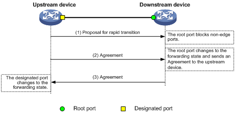
Figure 17 Rapid state transition of an RSTP designated port
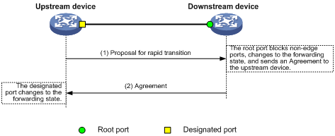
If the upstream device is a third-party device, the rapid state transition implementation might be limited as follows:
· The upstream device uses a rapid transition mechanism similar to that of RSTP.
· The downstream device runs MSTP and does not operate in RSTP mode.
In this case, the following occurs:
1. The root port on the downstream device receives no agreement from the upstream device.
2. It sends no agreement to the upstream device.
As a result, the designated port of the upstream device can transit to the forwarding state only after a period twice the forward delay.
To enable the designated port of the upstream device to transit its state rapidly, enable No Agreement Check on the downstream device's port.
Restrictions and guidelines
Configure No Agreement Check on the root port of your device, because this feature takes effect only if it's configured on root ports.
Prerequisites
Before you configure the No Agreement Check feature, complete the following tasks:
· Connect a device to a third-party upstream device that supports spanning tree protocols through a point-to-point link.
· Configure the same region name, revision level, and VLAN-to-instance mappings on the two devices.
Procedure
Enable the No Agreement Check feature on the root port.
1. Enter system view.
system-view
2. Enter interface view.
interface interface-type interface-number
3. Enable No Agreement Check.
stp no-agreement-check
By default, No Agreement Check is disabled.
Configuring TC Snooping
About TC Snooping
As shown in Figure 18, an IRF fabric connects to two user networks through double links.
· Device A and Device B form the IRF fabric.
· The spanning tree feature is disabled on Device A and Device B and enabled on all devices in user network 1 and user network 2.
· The IRF fabric transparently transmits BPDUs for both user networks and is not involved in the calculation of spanning trees.
When the network topology changes, it takes time for the IRF fabric to update its MAC address table and ARP table. During this period, traffic in the network might be interrupted.
Figure 18 TC Snooping application scenario
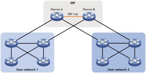
To avoid traffic interruption, you can enable TC Snooping on the IRF fabric. After receiving a TC-BPDU through a port, the IRF fabric updates MAC address table and ARP table entries associated with the port's VLAN. In this way, TC Snooping prevents topology change from interrupting traffic forwarding in the network. For more information about the MAC address table and the ARP table, see "Configuring the MAC address table" and Layer 3—IP Services Configuration Guide.
Restrictions and guidelines
· TC Snooping and the spanning tree feature are mutually exclusive. You must globally disable the spanning tree feature before enabling TC Snooping.
· TC Snooping does not support the PVST mode.
Procedure
1. Enter system view.
system-view
2. Globally disable the spanning tree feature.
undo stp global enable
By default, the spanning tree feature is disabled globally.
3. Enable TC Snooping.
stp tc-snooping
By default, TC Snooping is disabled.
Configuring protection features
Spanning tree protection tasks at a glance
All spanning tree protection tasks are optional.
· Configuring port role restriction
· Configuring TC-BPDU transmission restriction
Configuring BPDU guard
About BPDU guard
For access layer devices, the access ports can directly connect to the user terminals (such as PCs) or file servers. The access ports are configured as edge ports to allow rapid transition. When these ports receive configuration BPDUs, the system automatically sets the ports as non-edge ports and starts a new spanning tree calculation process. This causes a change of network topology. Under normal conditions, these ports should not receive configuration BPDUs. However, if someone uses configuration BPDUs maliciously to attack the devices, the network will become unstable.
The spanning tree protocol provides the BPDU guard feature to protect the system against such attacks. When edge ports receive configuration BPDUs on a device with BPDU guard enabled, the device performs the following operations:
· Shuts down these ports.
· Notifies the NMS that these ports have been shut down by the spanning tree protocol.
The device reactivates the ports that have been shut down when the port status detection timer expires. You can set this timer by using the shutdown-interval command. For more information about this command, see device management commands in Fundamentals Command Reference.
Restrictions and guidelines
You can configure the BPDU guard feature in system view or on a per-edge port basis. An edge port preferentially uses the port-specific BPDU guard setting. If the port-specific BPDU guard setting is not available, the edge port uses the global BPDU guard setting.
Configure BPDU guard on edge ports which directly connect to a user terminal rather than other device or shared LAN segment.
BPDU guard does not take effect on loopback-testing-enabled ports. For more information about loopback testing, see Ethernet interface configuration in Interface Configuration Guide.
Enabling BPDU guard in system view
1. Enter system view.
system-view
2. Enable BPDU guard globally.
stp bpdu-protection
By default, BPDU guard is globally disabled.
Configuring BPDU guard in interface view
1. Enter system view.
system-view
2. Enter interface view.
interface interface-type interface-number
3. Configure BPDU guard.
stp port bpdu-protection { enable | disable }
By default, the enabling status of BPDU guard on an interface is the same as that of global BPDU guard.
Enabling root guard
About root guard
Configure root guard on a designated port.
The root bridge and secondary root bridge of a spanning tree should be located in the same MST region. Especially for the CIST, the root bridge and secondary root bridge are put in a high-bandwidth core region during network design. However, due to possible configuration errors or malicious attacks in the network, the legal root bridge might receive a configuration BPDU with a higher priority. Another device supersedes the current legal root bridge, causing an undesired change of the network topology. The traffic that should go over high-speed links is switched to low-speed links, resulting in network congestion.
To prevent this situation, MSTP provides the root guard feature. If root guard is enabled on a port of a root bridge, this port plays the role of designated port on all MSTIs. After this port receives a configuration BPDU with a higher priority from an MSTI, it performs the following operations:
· Immediately sets that port to the listening state in the MSTI.
· Does not forward the received configuration BPDU.
This is equivalent to disconnecting the link connected to this port in the MSTI. If the port receives no BPDUs with a higher priority within twice the forwarding delay, it reverts to its original state.
Restrictions and guidelines
On a port, the loop guard feature and the root guard feature are mutually exclusive.
Procedure
1. Enter system view.
system-view
2. Enter interface view.
interface interface-type interface-number
3. Enable the root guard feature.
stp root-protection
By default, root guard is disabled.
Enabling loop guard
About loop guard
Configure loop guard on the root port and alternate ports of a device.
By continuing to receive BPDUs from the upstream device, a device can maintain the state of the root port and blocked ports. However, link congestion or unidirectional link failures might cause these ports to fail to receive BPDUs from the upstream devices. In this situation, the device reselects the following port roles:
· Those ports in forwarding state that failed to receive upstream BPDUs become designated ports.
· The blocked ports transit to the forwarding state.
As a result, loops occur in the switched network. The loop guard feature can suppress the occurrence of such loops.
The initial state of a loop guard-enabled port is discarding in every MSTI. When the port receives BPDUs, it transits its state. Otherwise, it stays in the discarding state to prevent temporary loops.
Restrictions and guidelines
Do not enable loop guard on a port that connects user terminals. Otherwise, the port stays in the discarding state in all MSTIs because it cannot receive BPDUs.
On a port, the loop guard feature is mutually exclusive with the root guard feature or the edge port setting.
A loop guard-enabled interface can receive BPDUs and transit from the discarding state to the forwarding state after two forward delays if one of the following events occurs:
· The state of the interface changes from down to up.
· The spanning tree feature is enabled on the up interface.
Procedure
1. Enter system view.
system-view
2. Enter interface view.
interface interface-type interface-number
3. Enable the loop guard feature.
stp loop-protection
By default, loop guard is disabled.
Configuring port role restriction
About port role restriction
Make this configuration on the port that connects to the user access network.
The bridge ID change of a device in the user access network might cause a change to the spanning tree topology in the core network. To avoid this problem, you can enable port role restriction on a port. With this feature enabled, when the port receives a superior BPDU, it becomes an alternate port rather than a root port.
Restrictions and guidelines
Use this feature with caution, because enabling port role restriction on a port might affect the connectivity of the spanning tree topology.
Procedure
1. Enter system view.
system-view
2. Enter interface view.
interface interface-type interface-number
3. Enable port role restriction.
stp role-restriction
By default, port role restriction is disabled.
Configuring TC-BPDU transmission restriction
About TC-BPDU transmission restriction
Make this configuration on the port that connects to the user access network.
The topology change to the user access network might cause the forwarding address changes to the core network. When the user access network topology is unstable, the user access network might affect the core network. To avoid this problem, you can enable TC-BPDU transmission restriction on a port. With this feature enabled, when the port receives a TC-BPDU, it does not forward the TC-BPDU to other ports.
Restrictions and guidelines
Enabling TC-BPDU transmission restriction on a port might cause the previous forwarding address table to fail to be updated when the topology changes.
Procedure
1. Enter system view.
system-view
2. Enter interface view.
interface interface-type interface-number
3. Enable TC-BPDU transmission restriction.
stp tc-restriction
By default, TC-BPDU transmission restriction is disabled.
Enabling TC-BPDU guard
About TC-BPDU guard
When a device receives topology change (TC) BPDUs (the BPDUs that notify devices of topology changes), it flushes its forwarding address entries. If someone uses TC-BPDUs to attack the device, the device will receive a large number of TC-BPDUs within a short time. Then, the device is busy with forwarding address entry flushing. This affects network stability.
TC-BPDU guard allows you to set the maximum number of immediate forwarding address entry flushes performed within 10 seconds after the device receives the first TC-BPDU. For TC-BPDUs received in excess of the limit, the device performs a forwarding address entry flush when the time period expires. This prevents frequent flushing of forwarding address entries.
Restrictions and guidelines
As a best practice, enable TC-BPDU guard.
Procedure
1. Enter system view.
system-view
2. Enable the TC-BPDU guard feature.
stp tc-protection
By default, TC-BPDU guard is enabled.
3. (Optional.) Configure the maximum number of forwarding address entry flushes that the device can perform every 10 seconds.
stp tc-protection threshold number
The default setting is 6.
Enabling PVST BPDU guard
About PVST BPDU guard
This feature takes effect only when the device is operating in MSTP mode.
An MSTP-enabled device forwards PVST BPDUs as data traffic because it cannot recognize PVST BPDUs. If a PVST-enabled device in another independent network receives the PVST BPDUs, a PVST calculation error might occur. To avoid PVST calculation errors, enable PVST BPDU guard on the MSTP-enabled device. The device shuts down a port if the port receives PVST BPDUs.
Procedure
1. Enter system view.
system-view
2. Enable PVST BPDU guard.
stp pvst-bpdu-protection
By default, PVST BPDU guard is disabled.
Disabling dispute guard
About dispute guard
Dispute guard can be triggered by unidirectional link failures. If an upstream port receives inferior BPDUs from a downstream designated port in forwarding or learning state because of a unidirectional link failure, a loop appears. Dispute guard blocks the upstream designated port to prevent the loop.
As shown in Figure 19, in normal conditions, the spanning tree calculation result is as follows:
· Device A is the root bridge, and Port A1 is a designated port.
· Port B1 is blocked.
When the link between Port A1 and Port B1 fails in the direction of Port A1 to Port B1 and becomes unidirectional, the following events occur:
1. Port A1 can only receive BPDUs and cannot send BPDUs to Port B1.
2. Port B1 does not receive BPDUs from Port A1 for a certain period of time.
3. Device B determines itself as the root bridge.
4. Port B1 sends its BPDUs to Port A1.
5. Port A1 determines the received BPDUs are inferior to its own BPDUs. A dispute is detected.
6. Dispute guard is triggered and blocks Port A1 to prevent a loop.
Figure 19 Dispute guard triggering scenario (on a designated port)
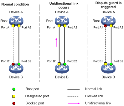
As shown in Figure 20, in normal conditions, Device A is the root bridge, and Port B1 and Port C1 are root ports. When the links between Device A and Device B become unidirectional (the links fail in the direction of Port A1 to Port B1), the following events occur:
1. Device B cannot receive BPDUs from Device A.
2. Device B determines itself as the root bridge.
3. Port B1 sends BPDUs in which the root bridge is Device B to Port C1.
4. Port C1 receives BPDUs from two root bridges, Device A and Device B. A dispute is detected.
5. Dispute guard is triggered and blocks Port C1 to avoid a loop.
Figure 20 Dispute guard triggering scenario (on a root port)
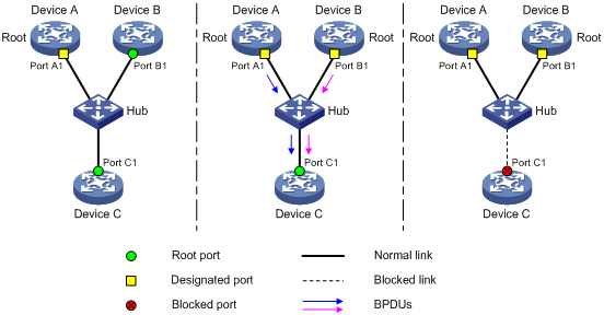
However, dispute guard might disrupt the network connectivity. You can disable dispute guard to avoid connectivity loss in VLAN networks. As shown in Figure 21, the spanning tree feature is disabled on Device B and enabled on Device A and device C. Device B transparently transmits BPDUs.
Device C cannot receive superior BPDUs of VLAN 1 from Device A because Port B1 of Device B is configured to deny packets of VLAN 1. Device C determines itself as the root bridge after a certain period of time. Then, Port C1 sends an inferior BPDU of VLAN 100 to Device A.
When Device A receives the inferior BPDU, dispute guard blocks Port A1, which causes traffic interruption. To ensure service continuity, you can disable dispute guard on Device A to prevent the link from being blocked.
Figure 21 Disabling dispute guard application scenario
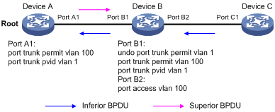
Restrictions and guidelines
You can disable dispute guard if the network does not have unidirectional link failures.
Procedure
1. Enter system view.
system-view
2. Disable dispute guard.
undo stp dispute-protection
By default, dispute guard is enabled.
Enabling the device to log events of detecting or receiving TC BPDUs
About spanning tree TC BPDU event logging
This feature allows the device to generate logs when it detects or receives TC BPDUs. This feature applies only to PVST mode.
Procedure
1. Enter system view.
system-view
2. Enable the device to log events of receiving or detecting TC BPDUs.
stp log enable tc
By default, the device does not generate logs when it detects or receives TC BPDUs.
Disabling the device from reactivating edge ports shut down by BPDU guard
About disabling the device from reactivating edge ports shut down by BPDU guard
BPDU guard shuts down edge ports that have received configuration BPDUs and notifies the NMS of the shutdown event.
The device reactivates the ports that have been shut down when the port status detection timer expires. You can set this timer by using the shutdown-interval command. For more information about this command, see device management commands in Fundamentals Command Reference.
Restrictions and guidelines
This feature prevents the device from reactivating edge ports shut down by BPDU guard after this feature is configured. The device does not bring up the shutdown ports if you execute the undo stp port shutdown permanent command. To bring up these ports, use the undo shutdown command.
Procedure
1. Enter system view.
system-view
2. Disable the device from reactivating edge ports shut down by BPDU guard.
stp port shutdown permanent
By default, the device reactivates an edge port shut down by BPDU guard after the port status detection timer expires.
Enabling BPDU transparent transmission on a port
Restrictions and guidelines
Perform this task to enable a port to transmit BPDUs transparently. Whether the spanning tree protocols are enabled on a port does not affect the BPDU transparent transmission feature.
If this feature and the spanning tree protocol are enabled on a port which is inferior to its downstream port, the downstream port can receive BPDUs from that port. To prevent network flapping caused by this problem, disable the spanning tree protocol before you enable BPDU transparent transmission on the port.
Procedure
1. Enter system view.
system-view
2. Enter interface view.
interface interface-type interface-number
3. Enable BPDU transparent transmission.
stp transparent enable
By default, the BPDU transparent transmission feature is disabled on a port.
Enabling SNMP notifications for new-root election and topology change events
About spanning tree SNMP notifications
This task enables the device to generate logs and report new-root election events or spanning tree topology changes to SNMP. For the event notifications to be sent correctly, you must also configure SNMP on the device. For more information about SNMP configuration, see the network management and monitoring configuration guide for the device.
When you use the snmp-agent trap enable stp [ new-root | tc ] command, follow these guidelines:
· The new-root keyword applies only to STP, MSTP, and RSTP modes.
· The tc keyword applies only to PVST mode.
· In STP, MSTP, or RSTP mode, the snmp-agent trap enable stp command enables SNMP notifications for new-root election events.
· In PVST mode, the snmp-agent trap enable stp command enables SNMP notifications for spanning tree topology changes.
Procedure
1. Enter system view.
system-view
2. Enable SNMP notifications for new-root election and topology change events.
snmp-agent trap enable stp [ new-root | tc ]
The default settings are as follows:
¡ SNMP notifications are disabled for new-root election events.
¡ In MSTP mode, SNMP notifications are enabled in MSTI 0 and disabled in other MSTIs for spanning tree topology changes.
¡ In PVST mode, SNMP notifications are disabled for spanning tree topology changes in all VLANs.
Display and maintenance commands for the spanning tree protocols
Execute display commands in any view and reset command in user view.
|
Task |
Command |
|
Display the spanning tree status and statistics. |
In standalone mode: display stp [ instance instance-list | vlan vlan-id-list ] [ interface interface-list | slot slot-number ] [ brief ] In IRF mode: display stp [ instance instance-list | vlan vlan-id-list ] [ interface interface-list | chassis chassis-number slot slot-number ] [ brief ] |
|
Display the port role calculation history for the specified MSTI or all MSTIs. |
In standalone mode: display stp [ instance instance-list | vlan vlan-id-list ] history [ slot slot-number ] In IRF mode: display stp [ instance instance-list | vlan vlan-id-list ] history [ chassis chassis-number slot slot-number ] |
|
Display the incoming and outgoing TC/TCN BPDU statistics by all ports in the specified MSTI or all MSTIs. |
In standalone mode: display stp [ instance instance-list | vlan vlan-id-list ] tc [ slot slot-number ] In IRF mode: display stp [ instance instance-list | vlan vlan-id-list ] tc [ chassis chassis-number slot slot-number ] |
|
Display history about ports blocked by spanning tree protection features. |
display stp abnormal-port |
|
Display BPDU statistics on ports. |
display stp bpdu-statistics [ interface interface-type interface-number [ instance instance-list ] ] |
|
Display information about ports shut down by spanning tree protection features. |
display stp down-port |
|
Display the MST region configuration information that has taken effect. |
display stp region-configuration |
|
Display the root bridge information of all MSTIs. |
display stp root |
|
Clear the spanning tree statistics. |
reset stp [ interface interface-list ] |
Spanning tree configuration examples
Example: Configuring MSTP
Network configuration
As shown in Figure 22, all devices on the network are in the same MST region. Device A and Device B work at the distribution layer. Device C and Device D work at the access layer.
Configure MSTP so that frames of different VLANs are forwarded along different spanning trees.
· VLAN 10 frames are forwarded along MSTI 1.
· VLAN 30 frames are forwarded along MSTI 3.
· VLAN 40 frames are forwarded along MSTI 4.
· VLAN 20 frames are forwarded along MSTI 0.
VLAN 10 and VLAN 30 are terminated on the distribution layer devices, and VLAN 40 is terminated on the access layer devices. The root bridges of MSTI 1 and MSTI 3 are Device A and Device B, respectively, and the root bridge of MSTI 4 is Device C.
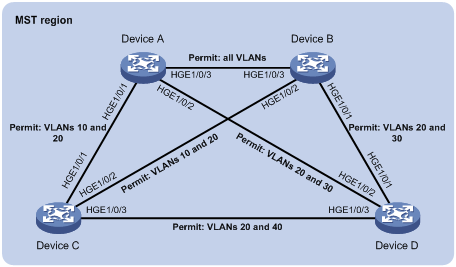
Procedure
|
|
IMPORTANT: By default, interfaces on the device are disabled (in ADM or Administratively Down state). To have an interface operate, you must use the undo shutdown command to enable that interface. |
1. Configure VLANs and VLAN member ports. (Details not shown.)
¡ Create VLAN 10, VLAN 20, and VLAN 30 on both Device A and Device B.
¡ Create VLAN 10, VLAN 20, and VLAN 40 on Device C.
¡ Create VLAN 20, VLAN 30, and VLAN 40 on Device D.
¡ Configure the ports on these devices as trunk ports and assign them to related VLANs.
2. Configure Device A:
# Enter MST region view, and configure the MST region name as example.
<DeviceA> system-view
[DeviceA] stp region-configuration
[DeviceA-mst-region] region-name example
# Map VLAN 10, VLAN 30, and VLAN 40 to MSTI 1, MSTI 3, and MSTI 4, respectively.
[DeviceA-mst-region] instance 1 vlan 10
[DeviceA-mst-region] instance 3 vlan 30
[DeviceA-mst-region] instance 4 vlan 40
# Configure the revision level of the MST region as 0.
[DeviceA-mst-region] revision-level 0
# Activate MST region configuration.
[DeviceA-mst-region] active region-configuration
[DeviceA-mst-region] quit
# Configure the Device A as the root bridge of MSTI 1.
[DeviceA] stp instance 1 root primary
# Enable the spanning tree feature globally.
[DeviceA] stp global enable
3. Configure Device B:
# Enter MST region view, and configure the MST region name as example.
<DeviceB> system-view
[DeviceB] stp region-configuration
[DeviceB-mst-region] region-name example
# Map VLAN 10, VLAN 30, and VLAN 40 to MSTI 1, MSTI 3, and MSTI 4, respectively.
[DeviceB-mst-region] instance 1 vlan 10
[DeviceB-mst-region] instance 3 vlan 30
[DeviceB-mst-region] instance 4 vlan 40
# Configure the revision level of the MST region as 0.
[DeviceB-mst-region] revision-level 0
# Activate MST region configuration.
[DeviceB-mst-region] active region-configuration
[DeviceB-mst-region] quit
# Configure Device B as the root bridge of MSTI 3.
[DeviceB] stp instance 3 root primary
# Enable the spanning tree feature globally.
[DeviceB] stp global enable
4. Configure Device C:
# Enter MST region view, and configure the MST region name as example.
<DeviceC> system-view
[DeviceC] stp region-configuration
[DeviceC-mst-region] region-name example
# Map VLAN 10, VLAN 30, and VLAN 40 to MSTI 1, MSTI 3, and MSTI 4, respectively.
[DeviceC-mst-region] instance 1 vlan 10
[DeviceC-mst-region] instance 3 vlan 30
[DeviceC-mst-region] instance 4 vlan 40
# Configure the revision level of the MST region as 0.
[DeviceC-mst-region] revision-level 0
# Activate MST region configuration.
[DeviceC-mst-region] active region-configuration
[DeviceC-mst-region] quit
# Configure the Device C as the root bridge of MSTI 4.
[DeviceC] stp instance 4 root primary
# Enable the spanning tree feature globally.
[DeviceC] stp global enable
5. Configure Device D:
# Enter MST region view, and configure the MST region name as example.
<DeviceD> system-view
[DeviceD] stp region-configuration
[DeviceD-mst-region] region-name example
# Map VLAN 10, VLAN 30, and VLAN 40 to MSTI 1, MSTI 3, and MSTI 4, respectively.
[DeviceD-mst-region] instance 1 vlan 10
[DeviceD-mst-region] instance 3 vlan 30
[DeviceD-mst-region] instance 4 vlan 40
# Configure the revision level of the MST region as 0.
[DeviceD-mst-region] revision-level 0
# Activate MST region configuration.
[DeviceD-mst-region] active region-configuration
[DeviceD-mst-region] quit
# Enable the spanning tree feature globally.
[DeviceD] stp global enable
Verifying the configuration
In this example, Device B has the lowest root bridge ID. As a result, Device B is elected as the root bridge in MSTI 0.
When the network is stable, you can use the display stp brief command to display brief spanning tree information on each device.
# Display brief spanning tree information on Device A.
[DeviceA] display stp brief
MST ID Port Role STP State Protection
0 HundredGigE1/0/1 ALTE DISCARDING NONE
0 HundredGigE1/0/2 DESI FORWARDING NONE
0 HundredGigE1/0/3 ROOT FORWARDING NONE
1 HundredGigE1/0/1 DESI FORWARDING NONE
1 HundredGigE1/0/3 DESI FORWARDING NONE
3 HundredGigE1/0/2 DESI FORWARDING NONE
3 HundredGigE1/0/3 ROOT FORWARDING NONE
# Display brief spanning tree information on Device B.
[DeviceB] display stp brief
MST ID Port Role STP State Protection
0 HundredGigE1/0/1 DESI FORWARDING NONE
0 HundredGigE1/0/2 DESI FORWARDING NONE
0 HundredGigE1/0/3 DESI FORWARDING NONE
1 HundredGigE1/0/2 DESI FORWARDING NONE
1 HundredGigE1/0/3 ROOT FORWARDING NONE
3 HundredGigE1/0/1 DESI FORWARDING NONE
3 HundredGigE1/0/3 DESI FORWARDING NONE
# Display brief spanning tree information on Device C.
[DeviceC] display stp brief
MST ID Port Role STP State Protection
0 HundredGigE1/0/1 DESI FORWARDING NONE
0 HundredGigE1/0/2 ROOT FORWARDING NONE
0 HundredGigE1/0/3 DESI FORWARDING NONE
1 HundredGigE1/0/1 ROOT FORWARDING NONE
1 HundredGigE1/0/2 ALTE DISCARDING NONE
4 HundredGigE1/0/3 DESI FORWARDING NONE
# Display brief spanning tree information on Device D.
[DeviceD] display stp brief
MST ID Port Role STP State Protection
0 HundredGigE1/0/1 ROOT FORWARDING NONE
0 HundredGigE1/0/2 ALTE DISCARDING NONE
0 HundredGigE1/0/3 ALTE DISCARDING NONE
3 HundredGigE1/0/1 ROOT FORWARDING NONE
3 HundredGigE1/0/2 ALTE DISCARDING NONE
4 HundredGigE1/0/3 ROOT FORWARDING NONE
Based on the output, you can draw each MSTI mapped to each VLAN, as shown in Figure 23.
Figure 23 MSTIs mapped to different VLANs
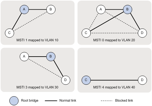
Example: Configuring PVST
Network configuration
As shown in Figure 24, Device A and Device B work at the distribution layer, and Device C and Device D work at the access layer.
Configure PVST to meet the following requirements:
· Frames of a VLAN are forwarded along the spanning trees of the VLAN.
· VLAN 10, VLAN 20, and VLAN 30 are terminated on the distribution layer devices, and VLAN 40 is terminated on the access layer devices.
· The root bridge of VLAN 10 and VLAN 20 is Device A.
· The root bridge of VLAN 30 is Device B.
· The root bridge of VLAN 40 is Device C.
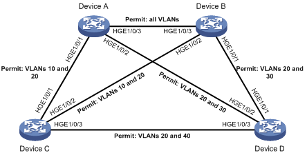
Procedure
|
|
IMPORTANT: By default, interfaces on the device are disabled (in ADM or Administratively Down state). To have an interface operate, you must use the undo shutdown command to enable that interface. |
1. Configure VLANs and VLAN member ports. (Details not shown.)
¡ Create VLAN 10, VLAN 20, and VLAN 30 on both Device A and Device B.
¡ Create VLAN 10, VLAN 20, and VLAN 40 on Device C.
¡ Create VLAN 20, VLAN 30, and VLAN 40 on Device D.
¡ Configure the ports on these devices as trunk ports and assign them to related VLANs.
2. Configure Device A:
# Set the spanning tree mode to PVST.
<DeviceA> system-view
[DeviceA] stp mode pvst
# Configure the device as the root bridge of VLAN 10 and VLAN 20.
[DeviceA] stp vlan 10 20 root primary
# Enable the spanning tree feature globally and in VLAN 10, VLAN 20, and VLAN 30.
[DeviceA] stp global enable
[DeviceA] stp vlan 10 20 30 enable
3. Configure Device B:
# Set the spanning tree mode to PVST.
<DeviceB> system-view
[DeviceB] stp mode pvst
# Configure the device as the root bridge of VLAN 30.
[DeviceB] stp vlan 30 root primary
# Enable the spanning tree feature globally and in VLAN 10, VLAN 20, and VLAN 30.
[DeviceB] stp global enable
[DeviceB] stp vlan 10 20 30 enable
4. Configure Device C:
# Set the spanning tree mode to PVST.
<DeviceC> system-view
[DeviceC] stp mode pvst
# Configure the device as the root bridge of VLAN 40.
[DeviceC] stp vlan 40 root primary
# Enable the spanning tree feature globally and in VLAN 10, VLAN 20, and VLAN 40.
[DeviceC] stp global enable
[DeviceC] stp vlan 10 20 40 enable
5. Configure Device D:
# Set the spanning tree mode to PVST.
<DeviceD> system-view
[DeviceD] stp mode pvst
# Enable the spanning tree feature globally and in VLAN 20, VLAN 30, and VLAN 40.
[DeviceD] stp global enable
[DeviceD] stp vlan 20 30 40 enable
Verifying the configuration
When the network is stable, you can use the display stp brief command to display brief spanning tree information on each device.
# Display brief spanning tree information on Device A.
[DeviceA] display stp brief
VLAN ID Port Role STP State Protection
10 HundredGigE1/0/1 DESI FORWARDING NONE
10 HundredGigE1/0/3 DESI FORWARDING NONE
20 HundredGigE1/0/1 DESI FORWARDING NONE
20 HundredGigE1/0/2 DESI FORWARDING NONE
20 HundredGigE1/0/3 DESI FORWARDING NONE
30 HundredGigE1/0/2 DESI FORWARDING NONE
30 HundredGigE1/0/3 ROOT FORWARDING NONE
# Display brief spanning tree information on Device B.
[DeviceB] display stp brief
VLAN ID Port Role STP State Protection
10 HundredGigE1/0/2 DESI FORWARDING NONE
10 HundredGigE1/0/3 ROOT FORWARDING NONE
20 HundredGigE1/0/1 DESI FORWARDING NONE
20 HundredGigE1/0/2 DESI FORWARDING NONE
20 HundredGigE1/0/3 ROOT FORWARDING NONE
30 HundredGigE1/0/1 DESI FORWARDING NONE
30 HundredGigE1/0/3 DESI FORWARDING NONE
# Display brief spanning tree information on Device C.
[DeviceC] display stp brief
VLAN ID Port Role STP State Protection
10 HundredGigE1/0/1 ROOT FORWARDING NONE
10 HundredGigE1/0/2 ALTE DISCARDING NONE
20 HundredGigE1/0/1 ROOT FORWARDING NONE
20 HundredGigE1/0/2 ALTE DISCARDING NONE
20 HundredGigE1/0/3 DESI FORWARDING NONE
40 HundredGigE1/0/3 DESI FORWARDING NONE
# Display brief spanning tree information on Device D.
[DeviceD] display stp brief
VLAN ID Port Role STP State Protection
20 HundredGigE1/0/1 ALTE DISCARDING NONE
20 HundredGigE1/0/2 ROOT FORWARDING NONE
20 HundredGigE1/0/3 ALTE DISCARDING NONE
30 HundredGigE1/0/1 ROOT FORWARDING NONE
30 HundredGigE1/0/2 ALTE DISCARDING NONE
40 HundredGigE1/0/3 ROOT FORWARDING NONE
Based on the output, you can draw a topology for each VLAN spanning tree, as shown in Figure 25.
Figure 25 VLAN spanning tree topologies
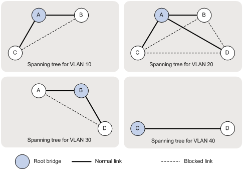
Example: Configuring DRNI with PVST
Network configuration
As shown in Figure 26, Device A and Device B work at the distribution layer, and Device C and Device D work at the access layer.
Configure DRNI on Device A and Device B. In the DR system, Device A is the primary DR device, and Device B is the secondary DR device.
Configure PVST on the devices to meet the following requirements:
· Frames of a VLAN are forwarded along the spanning trees of the VLAN.
· VLAN 10, VLAN 20, and VLAN 30 are terminated on the distribution layer devices.
· The root bridge of VLAN 10, VLAN 20, and VLAN 30 is the DR system formed by Device A and Device B.
|
|
NOTE: · As a best practice, do not connect ports on Device A and Device B that have the same port ID with each other, for example Layer 2 aggregate ports. Otherwise, when Device A and Device B communicate through the link, the spanning tree protocol determines that the device receives its own BPDUs. Loop guard will block the link, though spanning tree features are not affected. · You can view port IDs of interfaces on the device by using the display stp interface command. · The preceding restrictions do not apply to IPPs and their member ports. |
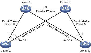
Procedure
|
|
IMPORTANT: By default, interfaces on the device are disabled (in ADM or Administratively Down state). To have an interface operate, you must use the undo shutdown command to enable that interface. |
1. Configure VLANs and VLAN member ports. (Details not shown.)
¡ Create VLAN 10, VLAN 20, and VLAN 30 on both Device A and Device B.
¡ Create VLAN 10, and VLAN 20 on Device C.
¡ Create VLAN 20, and VLAN 30 on Device D.
¡ Configure the ports on these devices as trunk ports and assign them to related VLANs.
2. Configure DRNI on Device A and Device B. (Details not shown.)
For more information about DRNI, see "Configuring DRNI."
3. Configure Device A:
# Set the spanning tree mode to PVST.
<DeviceA> system-view
[DeviceA] stp mode pvst
# Configure the device as the root bridge of VLAN 10 and VLAN 20.
[DeviceA] stp vlan 10 20 root primary
# Enable the spanning tree feature globally and in VLAN 10, VLAN 20, and VLAN 30.
[DeviceA] stp global enable
[DeviceA] stp vlan 10 20 30 enable
4. Configure Device B in the same way Device A is configured. (Details not shown.)
5. Configure Device C:
# Set the spanning tree mode to PVST.
<DeviceC> system-view
[DeviceC] stp mode pvst
# Enable the spanning tree feature globally and in VLAN 10, and VLAN 20.
[DeviceC] stp global enable
[DeviceC] stp vlan 10 20 enable
6. Configure Device D:
# Set the spanning tree mode to PVST.
<DeviceD> system-view
[DeviceD] stp mode pvst
# Enable the spanning tree feature globally and in VLAN 20, and VLAN 30.
[DeviceD] stp global enable
[DeviceD] stp vlan 20 30 enable
Verifying the configuration
When the network is stable, you can use the display stp brief command to display brief spanning tree information on each device.
# Display brief spanning tree information of the DR system on the primary DR device, Device A.
[DeviceA] display stp brief
VLAN ID Port Role STP State Protection
10 Bridge-Aggregation1 DESI FORWARDING NONE
20 Bridge-Aggregation1 DESI FORWARDING NONE
20 Bridge-Aggregation2 DESI FORWARDING NONE
30 Bridge-Aggregation2 DESI FORWARDING NONE
# Display brief spanning tree information on Device C.
[DeviceC] display stp brief
VLAN ID Port Role STP State Protection
10 Bridge-Aggregation1 ROOT FORWARDING NONE
20 Bridge-Aggregation1 ROOT FORWARDING NONE
# Display brief spanning tree information on Device D.
[DeviceD] display stp brief
VLAN ID Port Role STP State Protection
20 Bridge-Aggregation2 ROOT FORWARDING NONE
30 Bridge-Aggregation2 ROOT FORWARDING NONE