- Table of Contents
- Related Documents
-
| Title | Size | Download |
|---|---|---|
| 01-Text | 342.34 KB |
Power module overview
Functions
|
Feature |
Description |
|
Protection function |
Protection for over-current input, under-voltage input, over-voltage output, output short circuit, and overheat. |
|
Support for redundancy |
The power modules can work in 1+1 redundant mode, and support load sharing. |
|
Support for hot swapping |
You can plug or unplug a power module when the switch is operating properly. |
Technical specifications
|
Item |
Specifications |
|
Rated input voltage |
· LSVM1AC650: 100 VAC to 240V AC; 50 or 60 Hz · LSVM1DC650: –40VDC to –60 VDC |
|
Rated output voltage range |
12 V/5 V |
|
Maximum output current |
52.9 A (12 V)/3 A (5V) |
|
Maximum output power |
650 W |
|
Dimensions (H × W × D) |
40.2 × 50.5 × 300 mm (1.58 × 1.99 × 11.81 in) |
|
Operating temperature |
LSVM1AC650: –5°C to 50°C (23°F to 122°F) LSVM1DC650: –5°C to 45°C (23°F to 113°F) |
|
Relative humidity |
5% to 95% |
Appearance
Figure 1 LSVM1AC650 appearance
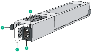
|
(1) Latch |
(2) Status LED |
|
(3) AC input socket |
(4) Handle |
Figure 2 LSVM1DC650 appearance
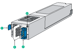
|
(1) Latch |
(2) Status LED |
|
(3) DC input socket |
(4) Handle |
LEDs
|
LED status |
Description |
|
Steady green |
The power module operates properly, and is in the active state. |
|
Blinking green |
The power module operates properly, and is in the standby state. |
|
Steady red |
The power module fails or enters the protected state. |
|
Red/Green blinking alternatively |
The power module alarms. The power module encounters exceptional power output problems, for example, over-voltage output, under-voltage output, over-current output, over-load, and over-heat, but does not enter the protected state. |
|
Blinking red |
The power module has no power input. The switch has two power modules. If one has power input, but the other does not, the status LED of the power module that has no power input blinks red. |
|
Off |
The power modules have no power input. |
Installing and removing a power module
Safety precautions
To avoid possible bodily injury and power module and device damage, follow these safety precautions:
· When installing and removing a power module, always wear an ESD-preventive wrist strap and make sure it makes good skin contact.
· Before installing the power module, to avoid power module and device damage, make sure that the voltage of the power supply system is the same as the rated voltage of the power module, and the output voltage of the power module is the same as the voltage required by the device.
· To avoid bodily injury, do not touch any cables or terminals of the power module.
· Do not place the power module in a wet area, and prevent liquid from flowing into the power module.
· To avoid power module damage, do not open the power module. When the internal circuits or components of the power module fail, contact the maintainer for examining and repairing.
Tools
When installing and removing a power module and power cables, you must wear an ESD-preventive wrist strap. Prepare it by yourself.
Installing and removing a power module
The installing and removing procedures of the LSVM1AC650 are similar to the LSVM1DC650. This section takes the LSVM1AC650 for example.
Installing the power module
To avoid bodily injury or device damage, follow the steps in Figure 3 to install the power module.
Figure 3 Power module installation procedure
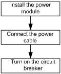
Step1 Put on the ESD-preventive wrist strap, making sure that the strap makes good skin contact and is well grounded.
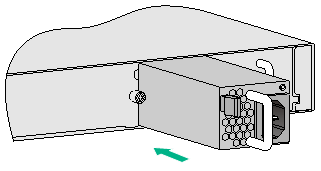
Step3 As shown in Figure 4, make sure that the power module is placed in a correct vertical direction. The power module and the power module slot are designed for avoiding upside down installation. If the vertical direction of the power module is incorrect, you cannot insert the power module completely into the slot. Hold the handle of the power module with one hand and the bottom of the power module with the other, and then slide the power module along the guide rails into the slot. When the power module is completely inserted into the slot, you can hear that the latch of the power module clicks into the slot.
Figure 4 Install the power module
|
|
CAUTION: · When you insert the power module into the slot, you can do that through slight inertia so that the back end of the power module can have a good touch with the backplane. · To avoid damaging or bending the terminals of the power module, if the insertion direction is improper during the installation, you must pull the power module out, adjust the direction, and insert it again. · Save the blank panel and the packaging box and packaging bag of the power module for future use. |
Connecting the power cable
Connecting the AC power cable
|
|
WARNING! · Make sure that each power cable has a separate circuit breaker. · Turn off the circuit breaker before connecting the power cable. |
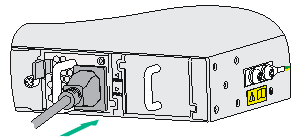
Step1 As shown in Figure 5, plug the female connector end of the AC power cable into the AC input socket on the switch.
Figure 5 Connect the AC power cable
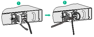
Step2 As shown in Figure 6, use the cable tie to secure the power cable to the handle of the power module.
Figure 6 Fix the AC power cable
Step3 Plug the other end of the AC power cable into the socket strip of the power supply system, and turn on the circuit breaker of the power supply system.
Step4 Check the LED on the power module. If the LED is steady green or blinking green, the power cable is successfully connected. If the LED is off or red, check the installation conditions, troubleshoot the problems, and try again until the LED is normal.
Connecting the DC power cable
Step1 As shown in Figure 7, insert the connector of the DC power cable into the DC input socket of the switch. The connector of the DC power cable and the DC input socket are designed for avoiding upside down installation. Make sure that the vertical direction of the connector is correct.
Figure 7 Connect the DC power cable
Step2 Use the cable tie to secure the power cable to the handle of the power module. For more information, see Step2 on page 9.
Step3 Connect the other end of the DC power cable to the DC power supply system.
Step4 Check the LED on the power module. If the LED is steady green or blinking green, the power cable is successfully connected. If the LED is off or red, check the installation conditions, troubleshoot the problems, and try again until the LED is normal.
Removing the power module
To avoid bodily injury or device damage, follow the steps in Figure 8 to remove the power module.
Figure 8 Power module removing procedure
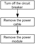
Step1 Turn off the circuit breaker of the power cable.
Step2 Put on the ESD-preventive wrist strap, making sure that the strap makes good skin contact and is well grounded.
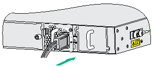
Figure 9 Remove the power cable connector
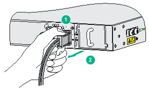
|
(1) Squeeze the tabs on the power cable connector |
(2) Pull the connector out |
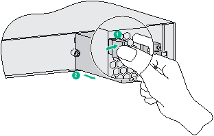
Step4 As shown in Figure 10, grasp the handle of the power module with one hand, use the thumb to press the latch towards the handle, and pull the power module at the same time. After pulling the power module part-way out, hold the bottom of the power module with the other hand, and pull the power module slowly along the guide rails out of the slot.
Figure 10 Remove the power module
Step5 Put the removed power module on an antistatic mat or into the initial package.
|
|
NOTE: If you do not insert another power module into the slot after removing the power module, install the blank panel to the power module slot to prevent dust from entering the chassis. |