- Table of Contents
- Related Documents
-
| Title | Size | Download |
|---|---|---|
| 04-PoE Configuration | 166.85 KB |
Contents
Enabling PoE for a PoE interface
Enabling the PSE to detect nonstandard PDs
Configuring the maximum PoE interface power
Configuring PoE power management
Configuring PoE interface power management
Configuring the PoE monitoring function
Configuring PSE power monitoring
Upgrading PSE processing software in service
Displaying and maintaining PoE
This chapter includes these sections:
· Configuring PoE power management
· Configuring the PoE monitoring function
· Configuring PoE interface through PoE profile
· Upgrading PSE processing software in service
· Displaying and maintaining PoE
|
|
NOTE: · The term "switch" or "device" in this document refers to the switching engine on a WX3000E wireless switch. · The WX3000E series comprises WX3024E and WX3010E wireless switches. · The port numbers in this document are for illustration only. |
PoE overview
Introduction to PoE
Power over Ethernet (PoE) enables a power sourcing equipment (PSE) to supply power to powered devices (PDs) from Ethernet interfaces through straight-through twisted pair cables.
Advantages
· Reliable—power is supplied in a centralized way so that it is very convenient to provide a backup power supply.
· Easy to connect—a network terminal requires no external power supply but only an Ethernet cable.
· Standard—in compliance with IEEE 802.3af, and a globally uniform power interface is adopted.
· Promising—it can be applied to IP telephones, wireless LAN access points (APs), portable chargers, card readers, web cameras, and data collectors.
PoE concepts
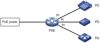
As shown in Figure 1, a PoE system comprises PoE power, PSE, power interface (PI), and PD.
1. PoE power—the whole PoE system is powered by the PoE power.
2. PSE—a PSE supplies power for PDs. A PSE can examine the Ethernet cables connected to PoE interfaces, search for PDs, classify them, and supply power to them. When detecting that a PD is unplugged, the PSE stops supplying power to the PD. A PSE can be built-in (Endpoint) or external (Midspan). A built-in PSE is integrated in a switch or router, and an external PSE is independent from a switch or router. The PSEs of H3C are built in, and can be classified into two types:
· Device with a single PSE—only one PSE is available on the device; so the whole device is considered as a PSE.
· Device with multiple PSEs—for a device with multiple PSEs, an interface card with the PoE power supply capability is a PSE. The system uses PSE IDs to identify different PSEs. To display the mapping between a PSE ID and the slot number of an interface card, execute the display poe device command .
3. PI—an Ethernet interface with the PoE capability is called PoE interface. Currently, a PoE interface can be an FE or GE interface.
4. PD—a PD accepts power from the PSE, including IP phones, wireless APs, chargers of portable devices, POS, and web cameras. The PD that is being powered by the PSE can be connected to another power supply unit for redundancy power backup.
Protocol specification
The protocol specification related to PoE is IEEE 802.3af.
PoE configuration task list
You can configure a PoE interface by using either of the following methods:
· At the command line interface (CLI).
· Through configuring the PoE profile and applying the PoE profile to the PoE interface.
To configure a single PoE interface, configure it at the CLI; to configure PoE interfaces in batches, use the PoE profile. For a PoE configuration parameter of a PoE interface, you can only select one mode (including modification and removal of a PoE interface).
Complete these tasks to configure PoE:
|
Task |
Remarks |
|
|
Required |
||
|
Optional |
||
|
Optional |
||
|
Optional |
||
|
Optional The device automatically monitors PDs when supplying power to them, so no configuration is required. |
||
|
Optional |
||
|
Optional |
||
|
Optional |
||
|
CAUTION: · Before configuring PoE, make sure that the PoE power supply and PSE are operating normally; otherwise, you cannot configure PoE or the configured PoE function does not take effect. · Turning off the PoE power supply during the startup of the device might cause the PoE configuration in the PoE profile invalid. |
Enabling PoE
Enabling PoE for a PoE interface
The system does not supply power to or reserve power for the PDs connected to a PoE interface if the PoE interface is not enabled with the PoE function.
You are allowed to enable PoE for a PoE interface if the PoE interface will not result in PoE power overload; otherwise, whether you can enable PoE for the PoE interface depends on whether the PoE interface is enabled with the PoE power management function (for the detailed description of the PoE interface power management function, see "Configuring PoE interface power management)".
· If the PoE interface is not enabled with the PoE power management function, you are not allowed to enable PoE for the PoE interface.
· If the PoE interface is enabled with the PoE power management function, you are allowed to enable PoE for the PoE interface (whether the PDs can be powered depends on other factors, for example, the power supply priority of the PoE interface).
The PSE supplies power for a PoE interface in the following modes:
· Over signal wires—the PSE uses the pairs (1, 2, 3, 6) for transmitting data in category 3/5 twisted pair cables to supply DC power while transmitting data to PDs.
· Over spare wires—the PSE uses the pairs (4, 5, 7, 8) not transmitting data in category 3/5 twisted pair cables to supply DC power to PDs.
|
|
NOTE: · When the sum of the power consumption of all powered PoE interfaces on a PSE exceeds the maximum power of the PSE, the system considers the PSE overloaded (The maximum PSE power is decided by the user configuration). · A PSE can supply power to a PD only when the selected power supply mode is supported by both the PSE and PD. If the PSE and PD support different power supply modes (for example, the PSE does not support power over spare wires, while the PD supports power over spare wires), you have to change the order of the lines in the twisted pair cable to supply power to the PD. |
Follow these steps to enable PoE for a PoE interface:
|
To do… |
Use the command… |
Remarks |
|
Enter system view |
system-view |
— |
|
Enter PoE interface view |
interface interface-type interface-number |
— |
|
Enable PoE for the PoE interface |
poe enable |
Required Disabled by default. |
|
Configure PoE interface power supply mode |
poe mode signal |
Optional signal (power over signal cables) by default. |
|
Configure a description for the PD connected to the PoE interface |
poe pd-description text |
Optional By default, no description for the PD connected to the PoE interface is available. |
Detecting PDs
Enabling the PSE to detect nonstandard PDs
There are standard PDs and nonstandard PDs. Usually, the PSE can detect only standard PDs and supply power to them. The PSE can detect nonstandard PDs and supply power to them only after the PSE is enabled to detect nonstandard PDs.
Follow these steps to enable the PSE to detect nonstandard PDs:
|
To do… |
Use the command… |
Remarks |
|
Enter system view |
system-view |
— |
|
Enable the PSE to detect nonstandard PDs |
poe legacy enable pse pse-id |
Required By default, the PSE can detect standard PDs rather than non standard PDs. |
Configuring the maximum PoE interface power
The maximum PoE interface power is the maximum power that the PoE interface can provide to the connected PD. If the power required by the PD is larger than the maximum PoE interface power, the PoE interface will not supply power to the PD.
Follow these steps to configure the maximum PSE power:
|
To do… |
Use the command… |
Remarks |
|
Enter system view |
system-view |
— |
|
Enter PoE interface view |
interface interface-type interface-number |
— |
|
Configure the maximum power for the PoE interface |
poe max-power max-power |
Optional 25000 milliwatts by default. |
Configuring PoE power management
Configuring PoE interface power management
The power supply priority of a PD depends on the priority of the PoE interface. The priority levels of PoE interfaces are critical, high and low in descending order. Power supply to a PD is subject to PoE interface power management policies.
All PSEs implement the same PoE interface power management policies. When a PSE supplies power to a PD, the following actions occur:
· If the PoE interface power management is not enabled, no power will be supplied to a new PD when the PSE power is overloaded.
· If the PoE interface power management priority policy is enabled, the PD with a lower priority is first powered off to guarantee the power supply to the PD with a higher priority when the PSE power is overloaded.
|
|
NOTE: · 20 watts guard band is reserved for each PoE interface on the device to prevent a PD from being powered off because of a sudden increase of the PD power. When the remaining power of the PSE where the PoE interface resides is lower than 20 watts and no priority is configured for the PoE interface, the PSE does not supply power to the new PD; when the remaining power of the PSE where the PoE interface resides is lower than 20 watts, but priority is configured for the PoE interface, the interface with a higher priority can preempt the power of the interface with a lower priority to ensure the normal working of the higher priority interface. · If the sudden increase of the PD power results in PSE power overload, power supply to the PD on the PoE interface with a lower priority will be stopped to ensure the power supply to the PD with a higher priority. |
If the guaranteed remaining PSE power (the maximum PSE power minus the power allocated to the critical PoE interface, regardless of whether PoE is enabled for the PoE interface) is lower than the maximum power of the PoE interface, you will fail to set the priority of the PoE interface to critical. Otherwise, you can succeed in setting the priority to critical, and this PoE interface will preempt the power of other PoE interfaces with a lower priority level. In the latter case, the PoE interfaces whose power is preempted will be powered off, but their configurations will remain unchanged. When you change the priority of a PoE interface from critical to a lower level, the PDs connecting to other PoE interfaces will have an opportunity of being powered.
Configuration prerequisites
Enable PoE for PoE interfaces.
Configuration procedure
Follow these steps to configure PoE interface power management:
|
To do… |
Use the command… |
Remarks |
|
Enter system view |
system-view |
— |
|
Enter PoE interface view |
interface interface-type interface-number |
— |
|
Configure the power supply priority for a PoE interface |
poe priority { critical | high | low } |
Optional low by default. |
Configuring the PoE monitoring function
With the PoE monitoring function enabled, the system monitors the parameter values related to PSE, PD, and device temperature in real time. When a specific value exceeds the limited range, the system automatically takes some measures to protect itself.
Configuring PSE power monitoring
When the PSE power exceeds or drops below the specified threshold, the system sends trap messages.
Follow these steps to configure a power alarm threshold for the PSE:
|
To do… |
Use the command… |
Remarks |
|
Enter system view |
system-view |
— |
|
Configure a power alarm threshold for the PSE |
poe utilization-threshold utilization-threshold-value pse pse-id |
Optional 80% by default. |
Monitoring PD
When a PSE starts or ends power supply to a PD, the system sends a trap message.
Configuring PoE interface through PoE profile
You can configure a PoE interface either at the CLI or by using a PoE profile and applying the PoE profile to the specified PoE interface(s).
To configure a single PoE interface, configure it at the CLI; to configure PoE interfaces in batches, use a PoE profile.
A PoE profile is a collection of configurations that contain multiple PoE features. On large-scale networks, you can apply a PoE profile to multiple PoE interfaces, and these interfaces have the same PoE features. If the PoE interface connecting to a PD changes to another one, apply the PoE profile applied on the originally connected interface to the currently connected interface instead of reconfiguring the features defined in the PoE profile one by one, simplifying the PoE configurations.
You can define PoE configurations based on each PD, save the configurations for different PDs into different PoE profiles, and apply the PoE profiles to the access interfaces of PDs accordingly.
Configuring PoE profile
Follow these steps to configure a PoE profile:
|
To do… |
Use the command… |
Remarks |
|
Enter system view |
system-view |
— |
|
Create a PoE profile, and enter PoE profile view |
poe-profile profile-name [ index ] |
Required |
|
Enable PoE for the PoE interface |
poe enable |
Required Disabled by default. |
|
Configure the maximum power for the PoE interface |
poe max-power max-power |
Optional 25000 milliwatts by default. |
|
Configure PoE power supply mode for the PoE interface |
poe mode signal |
Optional signal (power over signal cables) by default. |
|
Configure power supply priority for the PoE interface |
poe priority { critical | high | low } |
Optional low by default. |
|
|
CAUTION: · If a PoE profile is applied, it cannot be deleted or modified before you cancel its application. · The poe max-power max-power and poe priority { critical | high | low } commands must be configured in only one way, that is, either at the CLI or by configuring PoE profile. · A PoE parameter on a PoE interface must be configured, modified and deleted in only one way. If a parameter configured in a way (for example, at the CLI) is then configured in the other way (for example, through PoE profile), the latter configuration fails and the original one is still effective. To make the latter configuration effective, you must cancel the original one first. |
You can apply a PoE profile in either system view or interface view. If you perform application to a PoE interface in both views, the latter application takes effect. To apply a PoE profile to multiple PoE interfaces, the system view is more efficient.
Follow these steps to apply the PoE profile in system view:
|
To do… |
Use the command… |
Remarks |
|
Enter system view |
system-view |
— |
|
Apply the PoE profile to one or multiple PoE interfaces |
apply poe-profile { index index | name profile-name } interface interface-range |
Required |
Follow these steps to apply the PoE profile in interface view:
|
To do… |
Use the command… |
Remarks |
|
Enter system view |
system-view |
— |
|
Enter PoE interface view |
interface interface-type interface-number |
— |
|
Apply the PoE profile to the current PoE interface |
apply poe-profile { index index | name profile-name } |
Required |
|
|
CAUTION: A PoE profile can be applied to multiple PoE interfaces, while a PoE interface can be applied with only one PoE profile. |
Upgrading PSE processing software in service
You can upgrade the PSE processing software in service in either of the following two modes:
· refresh mode—this mode enables you to update the PSE processing software without deleting it. Normally, you can upgrade the PSE processing software in the refresh mode through the command line.
· full mode—this mode deletes the PSE processing software and reloads it. If the PSE processing software is damaged (in this case, you can execute none of PoE commands successfully), you can upgrade the PSE processing software in full mode to restore the PSE function.
In-service PSE processing software upgrade may be unexpectedly interrupted (for example, an error results in device reboot). If you fail to upgrade the PSE processing software in full mode after reboot, you can power off the device and restart it before upgrading it in full mode again. After upgrade, restart the device manually to make the new PSE processing software take effect.
Follow these steps to upgrade the PSE processing software in service:
|
To do… |
Use the command… |
Remarks |
|
Enter system view |
system-view |
— |
|
Upgrade the PSE processing software in service |
poe update { full | refresh } filename pse pse-id |
Required |
Displaying and maintaining PoE
|
To do… |
Use the command… |
Remarks |
|
Display PSE information |
display poe device [ | { begin | exclude | include } regular-expression ] |
Available in any view |
|
Display the power supply state of the specified PoE interface |
display poe interface [ interface-type interface-number ] [ | { begin | exclude | include } regular-expression ] |
|
|
Display the power information of a PoE interface(s) |
display poe interface power [ interface-type interface-number ] [ | { begin | exclude | include } regular-expression ] |
|
|
Display the information of PSE |
display poe pse [ pse-id ] [ | { begin | exclude | include } regular-expression ] |
|
|
Display the power supply states of all PoE interfaces connected with the PSE |
display poe pse pse-id interface [ | { begin | exclude | include } regular-expression ] |
|
|
Display the power information of all PoE interfaces connected with the PSE |
display poe pse pse-id interface power [ | { begin | exclude | include } regular-expression ] |
|
|
Display all information of the configurations and applications of the PoE profile |
display poe-profile [ index index | name profile-name ] [ | { begin | exclude | include } regular-expression ] |
|
|
Display all information of the configurations and applications of the PoE profile applied to the specified PoE interface |
display poe-profile interface interface-type interface-number [ | { begin | exclude | include } regular-expression ] |
PoE configuration example
Network requirements
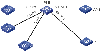
As shown in Figure 2, the device supplies power to PDs through its PoE interfaces.
· GigabitEthernet 1/0/1, GigabitEthernet 1/0/2, and GigabitEthernet 1/0/3 are connected to IP telephones.
· GigabitEthernet 1/0/11 and GigabitEthernet 1/0/12 are connected to APs.
· The power supply priority of IP telephones is higher than that of the APs, for which the PSE supplies power to IP telephones first when the PSE power is overloaded.
· The maximum power of AP2 connected to GigabitEthernet 1/0/12 does not exceed 9000 milliwatts.
Figure 2 Network diagram for PoE
Configuration procedure
# Enable PoE on GigabitEthernet 1/0/1, GigabitEthernet 1/0/2, and GigabitEthernet 1/0/3, and configure their power supply priority as critical.
<Sysname> system-view
[Sysname] interface gigabitethernet 1/0/1
[Sysname-GigabitEthernet1/0/1] poe enable
[Sysname-GigabitEthernet1/0/1] poe priority critical
[Sysname-GigabitEthernet1/0/1] quit
[Sysname] interface gigabitethernet 1/0/2
[Sysname-GigabitEthernet1/0/2] poe enable
[Sysname-GigabitEthernet1/0/2] poe priority critical
[Sysname-GigabitEthernet1/0/2] quit
[Sysname] interface gigabitethernet 1/0/3
[Sysname-GigabitEthernet1/0/3] poe enable
[Sysname-GigabitEthernet1/0/3] poe priority critical
[Sysname-GigabitEthernet1/0/3] quit
# Enable PoE on GigabitEthernet 1/0/11 and GigabitEthernet 10//12, and configure the maximum power of GigabitEthernet 1/0/12 as 9000 milliwatts.
[Sysname] interface gigabitethernet 1/0/11
[Sysname-GigabitEthernet1/0/11] poe enable
[Sysname-GigabitEthernet1/0/11] quit
[Sysname] interface gigabitethernet 1/0/12
[Sysname-GigabitEthernet1/0/12] poe enable
[Sysname-GigabitEthernet1/0/12] poe max-power 9000
Configuration verification
After the configuration takes effect, the IP telephones and AP devices are powered and can work normally.
Troubleshooting PoE
Symptom 1: Setting the priority of a PoE interface to critical fails.
Analysis:
· The guaranteed remaining power of the PSE is lower than the maximum power of the PoE interface.
· The priority of the PoE interface is already set.
Solution:
· In the first case, you can solve the problem by increasing the maximum PSE power, or by reducing the maximum power of the PoE interface when the guaranteed remaining power of the PSE cannot be modified.
· In the second case, you should first remove the priority already configured.
Symptom 2: Applying a PoE profile to a PoE interface fails.
Analysis:
· Some configurations in the PoE profile are already configured.
· Some configurations in the PoE profile do not meet the configuration requirements of the PoE interface.
· Another PoE profile is already applied to the PoE interface.
Solution:
· In the first case, you can solve the problem by removing the original configurations of those configurations.
· In the second case, you need to modify some configurations in the PoE profile.
· In the third case, you need to remove the application of the undesired PoE profile to the PoE interface.
Symptom 3: Provided that parameters are valid, configuring an AC input under-voltage threshold fails.
Analysis:
The AC input under-voltage threshold is greater than or equal to the AC input over-voltage threshold.
Solution:
You can drop the AC input under-voltage threshold below the AC input over-voltage threshold.