- Table of Contents
- Related Documents
-
| Title | Size | Download |
|---|---|---|
| 05-Smart Link Configuration | 210.68 KB |
Contents
Smart Link configuration task list
Configuring a Smart Link device
Configuring protected VLANs for a smart link group
Configuring member ports for a smart link group
Configuring role preemption for a smart link group
Enabling the sending of flush messages
Configuring an associated device
Enabling the receiving of flush messages
Displaying and maintaining Smart Link
Smart Link configuration examples
Single smart link group configuration example
Multiple smart link groups load sharing configuration example
This chapter includes these sections:
· Smart Link configuration task list
· Displaying and maintaining Smart Link
· Smart Link configuration examples
|
|
NOTE: · The term "switch" or "device" in this chapter refers to the switching engine on a WX3000E wireless switch. · The WX3000E series comprises WX3024E and WX3010E wireless switches. · The port numbers in this chapter are for illustration only. |
Smart Link overview
Background
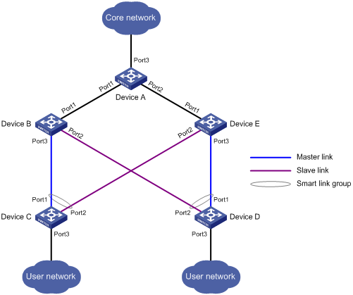
To avoid single-point failures and guarantee network reliability, downstream devices are usually dual-homed to upstream devices, as shown in Figure 1.
Figure 1 Diagram for a dual uplink network
To remove network loops on a dual-homed network, you can use a spanning tree protocol. The problem with STP, however, is that STP convergence time is long, which makes it not suitable for users who have high demand on convergence speed.
|
|
NOTE: For more information about STP, see the Layer 2 Configuration Guide. |
Smart Link is a feature developed to address the slow convergence issue with STP. It provides link redundancy as well as fast convergence in a dual uplink network, allowing the backup link to take over quickly when the primary link fails. To sum up, Smart Link has the following features:
· Dedicated to dual uplink networks
· Subsecond convergence
· Easy to configure
Terminology
Smart link group
A smart link group consists of only two member ports: the master and the slave ports. At a time, only one port is active for forwarding, and the other port is blocked and in the standby state. When link failure occurs on the active port due to port shutdown or presence of unidirectional link for example, the standby port becomes active to take over and the original active port transits to the blocked state.
As shown in Figure 1, Port 1 and Port 2 of Device C and Port 1 and Port 2 of Device D each form a smart link group, with Port 1 being active and Port 2 being standby.
Master/slave port
Master port and slave port are two port roles in a smart link group. When both ports in a smart link group are up, the master port preferentially transits to the forwarding state, and the slave port stays in the standby state. Once the master port fails, the slave port takes over to forward traffic. As shown in Figure 1, you can configure Port 1 of Device C and that of Device D as master ports, and Port 2 of Device C and that of Device D slave ports.
Master/slave link
Flush message
Flush messages are used by a smart link group to notify other devices to refresh their MAC address forwarding entries and ARP/ND entries when link switchover occurs in the smart link group. Flush messages are common multicast data packets, and will be dropped by a blocked receiving port.
Protected VLAN
A smart link group controls the forwarding state of some data VLANs (protected VLANs). Different smart link groups on a port control different protected VLANs. The state of the port in a protected VLAN is determined by the state of the port in the smart link group.
Transmit control VLAN
The transmit control VLAN is used for transmitting flush messages. When link switchover occurs, the devices (such as Device C and Device D in Figure 1) broadcast flush messages within the transmit control VLAN.
Receive control VLAN
The receive control VLAN is used for receiving and processing flush messages. When link switchover occurs, the devices (such as Device A, Device B, and Device E in Figure 1) receive and process flush messages in the receive control VLAN and refresh their MAC address forwarding entries and ARP/ND entries.
How Smart Link works
Link backup mechanism
As shown in Figure 1, the link on Port 1 of Device C is the master link, and the link on Port 2 of Device C is the slave link. Typically, Port 1 is in the forwarding state, and Port 2 is in the standby state. When the master link fails, Port 2 takes over to forward traffic and Port 1 is blocked and placed in the standby state.
|
|
NOTE: When a port switches to the forwarding state, the system outputs log information to notify the user of the port state change. |
Topology change mechanism
As link switchover can outdate the MAC address forwarding entries and ARP/ND entries on all devices, you need a forwarding entry update mechanism to ensure proper transmission. By far, the following two update mechanisms are provided:
· Uplink traffic-triggered MAC address learning, where update is triggered by uplink traffic. This mechanism is applicable to environments with devices not supporting Smart Link, including devices of other vendors’.
· Flush update where a Smart Link-enabled device updates its information by transmitting flush messages over the backup link to its upstream devices. This mechanism requires the upstream devices to be capable of recognizing Smart Link flush messages to update its MAC address forwarding entries and ARP/ND entries.
Role preemption mechanism
As shown in Figure 1, the link on Port 1 of Device C is the master link, and the link on Port 2 of Device C is the slave link. Once the master link fails, Port 1 is automatically blocked and placed in the standby state, and Port 2 takes over to forward traffic. When the master link recovers,
· If the smart link group is not configured with role preemption, to keep traffic forwarding stable, Port 1 that has been blocked due to link failure does not immediately take over to forward traffic. Rather, it stays blocked until the next link switchover.
· If the smart link group is configured with role preemption, Port 1 takes over to forward traffic as soon as its link recovers, and Port 2 is automatically blocked and placed in the standby state.
Load sharing mechanism
A ring network may carry traffic of multiple VLANs. Smart Link can forward traffic of different VLANs in different smart link groups, implementing load sharing.
To implement load sharing, you can assign a port to multiple smart link groups (each configured with different protected VLANs), making sure that the state of the port is different in these smart link groups. In this way, traffic of different VLANs can be forwarded along different paths.
You can configure protected VLANs for a smart link group by referencing Multiple Spanning Tree Instances (MSTIs).
Smart Link configuration task list
Complete the following tasks to configure Smart Link:
|
Task |
Remarks |
|
|
Required |
||
|
Required |
||
|
Optional |
||
|
Optional |
||
|
Required |
||
|
|
NOTE: · A smart link device is a device that supports Smart Link and is configured with a smart link group and a transmit control VLAN for flush message transmission. Device C and Device D in Figure 1 are two examples of smart link devices. · An associated device is a device that supports Smart Link, and receives flush messages sent from the specified control VLAN. Device A, Device B, and Device E in Figure 1 are examples of associated devices. |
Configuring a Smart Link device
Configuration prerequisites
· Before configuring a port as a smart link group member, shut down the port to prevent loops. You can bring up the port only after completing the smart link group configuration.
· Disable the STP on the ports you want to add to the smart link group, and make sure that the ports are not member ports of any aggregation group.
|
|
NOTE: A loop may occur on the network during the time when the STP is disabled but Smart Link has not yet taken effect on a port. |
Configuring protected VLANs for a smart link group
Follow these steps to configure the protected VLANs for a smart link group:
|
To do… |
Use the command… |
Remarks |
|
Enter system view |
system-view |
— |
|
Create a smart link group and enter smart link group view |
smart-link group group-id |
— |
|
Configure protected VLANs for the smart link group |
protected-vlan reference-instance instance-id-list |
Required By default, no protected VLAN is configured for a smart link group. |
|
|
NOTE: The protected-vlan command protects VLANs for a smart link group by referencing MSTIs. You can use the display stp region-configuration command to view the VLANs mapped to the referenced MSTIs. For more information, see the Layer 2 Configuration Guide. |
Configuring member ports for a smart link group
You can configure member ports for a smart link group either in smart link group view or in interface view. The configurations made in these two views have the same effect.
In smart link group view
Follow these steps to configure member ports for a smart link group in smart link group view:
|
To do… |
Use the command… |
Remarks |
|
Enter system view |
system-view |
— |
|
Create a smart link group and enter smart link group view |
smart-link group group-id |
— |
|
Configure member ports for a smart link group |
port interface-type interface-number { master | slave } |
Required |
In interface view
Follow these steps to configure member ports for a smart link group in interface view:
|
To do… |
Use the command… |
Remarks |
|
Enter system view |
system-view |
— |
|
Enter Ethernet interface view or layer 2 aggregate interface view |
interface interface-type interface-number |
— |
|
Configure member ports for a smart link group |
port smart-link group group-id { master | slave } |
Required |
Configuring role preemption for a smart link group
Follow these steps to configure role preemption for a smart link group:
|
To do… |
Use the command… |
Remarks |
|
Enter system view |
system-view |
— |
|
Create a smart link group and enter smart link group view |
smart-link group group-id |
— |
|
Enable role preemption |
preemption mode role |
Required Disabled by default |
|
Configure the preemption delay |
preemption delay delay-time |
Optional 1 second by default |
|
|
NOTE: The preemption delay configuration takes effect only after role preemption is enabled. |
Enabling the sending of flush messages
Follow these steps to enable the sending of flush messages:
|
To do… |
Use the command… |
Remarks |
|
Enter system view |
system-view |
— |
|
Create a smart link group and enter smart link group view |
smart-link group group-id |
Required |
|
Enable flush update in the specified control VLAN |
flush enable [ control-vlan vlan-id ] |
Optional By default, flush update is enabled, and VLAN 1 is the control VLAN. |
|
|
NOTE: · The control VLAN configured for a smart link group must be different from that configured for any other smart link group. · Make sure that the configured control VLAN already exists, and assign the smart link group member ports to the control VLAN. · The control VLAN of a smart link group should also be one of its protected VLANs. Do not remove the control VLAN. Otherwise, flush messages cannot be sent properly. |
Configuring an associated device
Enabling the receiving of flush messages
You do not need to enable all ports on the associated devices to receive flush messages sent from the transmit control VLAN, only those on the master and slave links between the smart link device and the destination device.
Follow these steps to enable the receiving of flush messages:
|
To do… |
Use the command… |
Remarks |
|
Enter system view |
system-view |
— |
|
Enter Ethernet interface view or Layer 2 aggregate interface view |
interface interface-type interface-number |
— |
|
Configure the control VLANs for receiving flush messages |
smart-link flush enable [ control-vlan vlan-id-list ] |
Required By default, no control VLAN exists for receiving flush messages. |
|
|
NOTE: · Configure all the control VLANs to receive flush messages. · If no control VLAN is specified for processing flush messages, the device forwards the received flush messages without processing them. · Make sure that the receive control VLAN is the same as the transmit control VLAN configured on the smart link device. If they are not the same, the associated device will forward the received flush messages directly without any processing. · Do not remove the control VLANs. Otherwise, flush messages cannot be sent properly. · Make sure that the control VLANs are existing VLANs, and assign the ports capable of receiving flush messages to the control VLANs. |
Displaying and maintaining Smart Link
|
To do... |
Use the command… |
Remarks |
|
Display smart link group information |
display smart-link group { group-id | all } [ | { begin | exclude | include } regular-expression ] |
Available in any view |
|
Display information about the received flush messages |
display smart-link flush [ | { begin | exclude | include } regular-expression ] |
Available in any view |
|
Clear the statistics about flush messages |
reset smart-link statistics |
Available in user view |
Smart Link configuration examples
Single smart link group configuration example
Network requirements
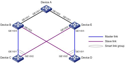
As shown in Figure 2:
· Device C and Device D are smart link devices, and Device A, Device B, and Device E are associated devices. Traffic of VLANs 1 through 30 on Device C and Device D are dually uplinked to Device A.
· Configure Smart Link on Device C and Device D for dual uplink backup.
Figure 2 Network diagram for single smart link group configuration
Configuration procedure
1. Configuration on Device C
# Create VLANs 1 through 30, map these VLANs to MSTI 1, and activate the MST region configuration.
<DeviceC> system-view
[DeviceC] vlan 1 to 30
[DeviceC] stp region-configuration
[DeviceC-mst-region] instance 1 vlan 1 to 30
[DeviceC-mst-region] active region-configuration
[DeviceC-mst-region] quit
# Shut down GigabitEthernet 1/0/1 and GigabitEthernet 1/0/2, disable STP on GigabitEthernet 1/0/1 and GigabitEthernet 1/0/2 separately, configure them as trunk ports, and assign them to VLANs 1 through 30.
[DeviceC] interface gigabitethernet 1/0/1
[DeviceC-GigabitEthernet1/0/1] shutdown
[DeviceC-GigabitEthernet1/0/1] undo stp enable
[DeviceC-GigabitEthernet1/0/1] port link-type trunk
[DeviceC-GigabitEthernet1/0/1] port trunk permit vlan 1 to 30
[DeviceC-GigabitEthernet1/0/1] quit
[DeviceC] interface gigabitethernet 1/0/2
[DeviceC-GigabitEthernet1/0/2] shutdown
[DeviceC-GigabitEthernet1/0/2] undo stp enable
[DeviceC-GigabitEthernet1/0/2] port link-type trunk
[DeviceC-GigabitEthernet1/0/2] port trunk permit vlan 1 to 30
[DeviceC-GigabitEthernet1/0/2] quit
# Create smart link group 1, and configure all VLANs mapped to MSTI 1 as the protected VLANs.
[DeviceC] smart-link group 1
[DeviceC-smlk-group1] protected-vlan reference-instance 1
# Configure GigabitEthernet 1/0/1 as the master port and GigabitEthernet 1/0/2 as the slave port for smart link group 1.
[DeviceC-smlk-group1] port ethernet1/1 master
[DeviceC-smlk-group1] port ethernet1/2 slave
# Enable flush message sending in smart link group 1.
[DeviceC-smlk-group1] flush enable
[DeviceC-smlk-group1] quit
# Bring up GigabitEthernet 1/0/1 and GigabitEthernet 1/0/2 again.
[DeviceC] interface gigabitethernet 1/0/1
[DeviceC-GigabitEthernet1/0/1] undo shutdown
[DeviceC-GigabitEthernet1/0/1] quit
[DeviceC] interface gigabitethernet 1/0/2
[DeviceC-GigabitEthernet1/0/2] undo shutdown
[DeviceC-GigabitEthernet1/0/2] quit
2. Configuration on Device D
# Create VLANs 1 through 30, map these VLANs to MSTI 1, and activate the MST region configuration.
<DeviceD> system-view
[DeviceD] vlan 1 to 30
[DeviceD] stp region-configuration
[DeviceD-mst-region] instance 1 vlan 1 to 30
[DeviceD-mst-region] active region-configuration
[DeviceD-mst-region] quit
# Shut down GigabitEthernet 1/0/1 and GigabitEthernet 1/0/2, disable STP on GigabitEthernet 1/0/1 and GigabitEthernet 1/0/2 separately, configure them as trunk ports, and assign them to VLANs 1 through 30.
[DeviceD] interface gigabitethernet 1/0/1
[DeviceD-GigabitEthernet1/0/1] shutdown
[DeviceD-GigabitEthernet1/0/1] undo stp enable
[DeviceD-GigabitEthernet1/0/1] port link-type trunk
[DeviceD-GigabitEthernet1/0/1] port trunk permit vlan 1 to 30
[DeviceD-GigabitEthernet1/0/1] quit
[DeviceD] interface gigabitethernet 1/0/2
[DeviceD-GigabitEthernet1/0/2] shutdown
[DeviceD-GigabitEthernet1/0/2] undo stp enable
[DeviceD-GigabitEthernet1/0/2] port link-type trunk
[DeviceD-GigabitEthernet1/0/2] port trunk permit vlan 1 to 30
[DeviceD-GigabitEthernet1/0/2] quit
# Create smart link group 1, and configure all VLANs mapped to MSTI 1 as the protected VLANs.
[DeviceD] smart-link group 1
[DeviceD-smlk-group1] protected-vlan reference-instance 1
# Configure GigabitEthernet 1/0/1 as the master port and GigabitEthernet 1/0/2 as the slave port for smart link group 1.
[DeviceD-smlk-group1] port ethernet1/1 master
[DeviceD-smlk-group1] port ethernet1/2 slave
# Enable flush message sending in smart link group 1
[DeviceD-smlk-group1] flush enable
[DeviceD-smlk-group1] quit
# Bring up GigabitEthernet 1/0/1 and GigabitEthernet 1/0/2 again.
[DeviceD] interface gigabitethernet 1/0/1
[DeviceD-GigabitEthernet1/0/1] undo shutdown
[DeviceD-GigabitEthernet1/0/1] quit
[DeviceD] interface gigabitethernet 1/0/2
[DeviceD-GigabitEthernet1/0/2] undo shutdown
[DeviceD-GigabitEthernet1/0/2] quit
3. Configuration on Device B
# Create VLANs 1 through 30.
<DeviceB> system-view
[DeviceB] vlan 1 to 30
# Configure GigabitEthernet 1/0/1, GigabitEthernet 1/0/2, and GigabitEthernet 1/0/3 as trunk ports, and assign them to VLANs 1 through 30. Enable flush message receiving on them
[DeviceB] interface gigabitethernet 1/0/1
[DeviceB-GigabitEthernet1/0/1] port link-type trunk
[DeviceB-GigabitEthernet1/0/1] port trunk permit vlan 1 to 30
[DeviceB-GigabitEthernet1/0/1] smart-link flush enable
[DeviceB-GigabitEthernet1/0/1] quit
[DeviceB] interface gigabitethernet 1/0/2
[DeviceB-GigabitEthernet1/0/2] port link-type trunk
[DeviceB-GigabitEthernet1/0/2] port trunk permit vlan 1 to 30
[DeviceB-GigabitEthernet1/0/2] smart-link flush enable
[DeviceB-GigabitEthernet1/0/2] quit
[DeviceB] interface gigabitethernet 1/0/3
[DeviceB-GigabitEthernet1/0/3] port link-type trunk
[DeviceB-GigabitEthernet1/0/3] port trunk permit vlan 1 to 30
[DeviceB-GigabitEthernet1/0/3] smart-link flush enable
[DeviceB-GigabitEthernet1/0/3] quit
4. Configuration on Device E
# Create VLANs 1 through 30.
<DeviceE> system-view
[DeviceE] vlan 1 to 30
# Configure GigabitEthernet 1/0/1, GigabitEthernet 1/0/2, and GigabitEthernet 1/0/3 as trunk ports, and assign them to VLANs 1 through 30. Enable flush message receiving on them
[DeviceE] interface gigabitethernet 1/0/1
[DeviceE-GigabitEthernet1/0/1] port link-type trunk
[DeviceE-GigabitEthernet1/0/1] port trunk permit vlan 1 to 30
[DeviceE-GigabitEthernet1/0/1] smart-link flush enable
[DeviceE-GigabitEthernet1/0/1] quit
[DeviceE] interface gigabitethernet 1/0/2
[DeviceE-GigabitEthernet1/0/2] port link-type trunk
[DeviceE-GigabitEthernet1/0/2] port trunk permit vlan 1 to 30
[DeviceE-GigabitEthernet1/0/2] smart-link flush enable
[DeviceE-GigabitEthernet1/0/2] quit
[DeviceE] interface gigabitethernet 1/0/3
[DeviceE-GigabitEthernet1/0/3] port link-type trunk
[DeviceE-GigabitEthernet1/0/3] port trunk permit vlan 1 to 30
[DeviceE-GigabitEthernet1/0/3] smart-link flush enable
[DeviceE-GigabitEthernet1/0/3] quit
5. Configuration on Device A
# Create VLANs 1 through 30.
<DeviceA> system-view
[DeviceA] vlan 1 to 30
# Configure GigabitEthernet 1/0/1 and GigabitEthernet 1/0/2 as trunk ports, and assign them to VLANs 1 through 30. Enable flush message receiving on them.
[DeviceA] interface gigabitethernet 1/0/1
[DeviceA-GigabitEthernet1/0/1] port link-type trunk
[DeviceA-GigabitEthernet1/0/1] port trunk permit vlan 1 to 30
[DeviceA-GigabitEthernet1/0/1] smart-link flush enable
[DeviceA-GigabitEthernet1/0/1] quit
[DeviceA] interface gigabitethernet 1/0/2
[DeviceA-GigabitEthernet1/0/2] port link-type trunk
[DeviceA-GigabitEthernet1/0/2] port trunk permit vlan 1 to 30
[DeviceA-GigabitEthernet1/0/2] smart-link flush enable
[DeviceA-GigabitEthernet1/0/2] quit
6. Verification
You can use the display smart-link group command to display the smart link group configuration on a device.
# Display the smart link group configuration on Device C.
[DeviceC] display smart-link group 1
Smart link group 1 information:
Device ID: 000f-e23d-5af0
Preemption mode: NONE
Preemption delay: 1(s)
Control VLAN: 1
Protected VLAN: Reference Instance 1
Member Role State Flush-count Last-flush-time
-----------------------------------------------------------------------------
GigabitEthernet1/0/1 MASTER ACTVIE 5 16:37:20 2010/02/21
GigabitEthernet1/0/2 SLAVE STANDBY 1 17:45:20 2010/02/21
You can use the display smart-link flush command to display the flush messages received on a device.
# Display the flush messages received on Device B.
[DeviceB] display smart-link flush
Received flush packets : 5
Receiving interface of the last flush packet : GigabitEthernet1/0/3
Receiving time of the last flush packet : 16:25:21 2009/02/21
Device ID of the last flush packet : 000f-e23d-5af0
Control VLAN of the last flush packet : 1
Multiple smart link groups load sharing configuration example
Network requirements
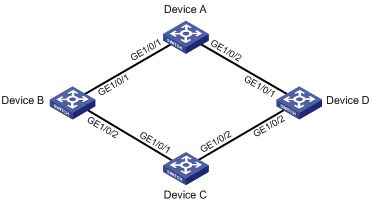
As shown in Figure 3:
· Device C is a smart link device, and Device A, Device B, and Device D are associated devices. Traffic of VLANs 1 through 200 on Device C are dually uplinked to Device A by Device B and Device D.
· Implement dual uplink backup and load sharing on Device C: traffic of VLANs 1 through 100 is uplinked to Device A by Device B; traffic of VLANs 101 through 200 is uplinked to Device A by Device D.
Figure 3 Network diagram for multiple smart link groups load sharing configuration
Configuration procedure
1. Configuration on Device C
# Create VLAN 1 through VLAN 200, map VLANs 1 through 100 to MSTI 1, and VLANs 101 through 200 to MSTI 2, and activate MST region configuration.
<DeviceC> system-view
[DeviceC] vlan 1 to 200
[DeviceC] stp region-configuration
[DeviceC-mst-region] instance 1 vlan 1 to 100
[DeviceC-mst-region] instance 2 vlan 101 to 200
[DeviceC-mst-region] active region-configuration
[DeviceC-mst-region] quit
# Shut down GigabitEthernet 1/0/1 and GigabitEthernet 1/0/2, disable STP on GigabitEthernet 1/0/1 and GigabitEthernet 1/0/2 separately, configure the ports as trunk ports, and assign them to VLAN 1 through VLAN 200.
[DeviceC] interface gigabitethernet 1/0/1
[DeviceC-GigabitEthernet1/0/1] shutdown
[DeviceC-GigabitEthernet1/0/1] undo stp enable
[DeviceC-GigabitEthernet1/0/1] port link-type trunk
[DeviceC-GigabitEthernet1/0/1] port trunk permit vlan 1 to 200
[DeviceC-GigabitEthernet1/0/1] quit
[DeviceC] interface gigabitethernet 1/0/2
[DeviceC-GigabitEthernet1/0/2] shutdown
[DeviceC-GigabitEthernet1/0/2] undo stp enable
[DeviceC-GigabitEthernet1/0/2] port link-type trunk
[DeviceC-GigabitEthernet1/0/2] port trunk permit vlan 1 to 200
[DeviceC-GigabitEthernet1/0/2] quit
# Create smart link group 1, and configure all VLANs mapped to MSTI 1 as the protected VLANs for smart link group 1.
[DeviceC] smart-link group 1
[DeviceC-smlk-group1] protected-vlan reference-instance 1
# Configure GigabitEthernet 1/0/1 as the master port and GigabitEthernet 1/0/2 as the slave port for smart link group 1.
[DeviceC-smlk-group1] port ethernet1/1 master
[DeviceC-smlk-group1] port ethernet1/2 slave
# Enable role preemption in smart link group 1, enable flush message sending, and configure VLAN 10 as the transmit control VLAN.
[DeviceC-smlk-group1] preemption mode role
[DeviceC-smlk-group-1] flush enable control-vlan 10
[DeviceC-smlk-group-1] quit
# Create smart link group 2, and configure all VLANs mapped to MSTI 2 as the protected VLANs for smart link group 2.
[DeviceC] smart-link group 2
[DeviceC-smlk-group2] protected-vlan reference-instance 2
# Configure GigabitEthernet 1/0/1 as the slave port and GigabitEthernet 1/0/2 as the master port for smart link group 2.
[DeviceC-smlk-group2] port ethernet1/2 master
[DeviceC-smlk-group2] port ethernet1/1 slave
# Enable role preemption in smart link group 2, enable flush message sending, and configure VLAN 101 as the transmit control VLAN.
[DeviceC-smlk-group2] preemption mode role
[DeviceC-smlk-group2] flush enable control-vlan 101
[DeviceC-smlk-group2] quit
# Bring up GigabitEthernet 1/0/1 and GigabitEthernet 1/0/2 again.
[DeviceC] interface gigabitethernet 1/0/1
[DeviceC-GigabitEthernet1/0/1] undo shutdown
[DeviceC-GigabitEthernet1/0/1] quit
[DeviceC] interface gigabitethernet 1/0/2
[DeviceC-GigabitEthernet1/0/2] undo shutdown
[DeviceC-GigabitEthernet1/0/2] quit
2. Configuration on Device B
# Create VLAN 1 through VLAN 200.
<DeviceB> system-view
[DeviceB] vlan 1 to 200
# Configure GigabitEthernet 1/0/1 and GigabitEthernet 1/0/2 as trunk ports and assign them to VLANs 1 through 200. Enable flush message receiving and configure VLAN 10 and VLAN 101 as the receive control VLANs on GigabitEthernet 1/0/1 and GigabitEthernet 1/0/2.
[DeviceB] interface gigabitethernet 1/0/1
[DeviceB-GigabitEthernet1/0/1] port link-type trunk
[DeviceB-GigabitEthernet1/0/1] port trunk permit vlan 1 to 200
[DeviceB-GigabitEthernet1/0/1] smart-link flush enable control-vlan 10 101
[DeviceB-GigabitEthernet1/0/1] quit
[DeviceB] interface gigabitethernet 1/0/2
[DeviceB-GigabitEthernet1/0/2] port link-type trunk
[DeviceB-GigabitEthernet1/0/2] port trunk permit vlan 1 to 200
[DeviceB-GigabitEthernet1/0/2] smart-link flush enable control-vlan 10 101
[DeviceB-GigabitEthernet1/0/2] quit
3. Configuration on Device D
# Create VLAN 1 through VLAN 200.
<DeviceD> system-view
[DeviceD] vlan 1 to 200
# Configure GigabitEthernet 1/0/1 and GigabitEthernet 1/0/2 as trunk ports and assign them to VLANs 1 through 200. Enable flush message receiving and configure VLAN 10 and VLAN 101 as the receive control VLANs on GigabitEthernet 1/0/1 and GigabitEthernet 1/0/2.
[DeviceD] interface gigabitethernet 1/0/1
[DeviceD-GigabitEthernet1/0/1] port link-type trunk
[DeviceD-GigabitEthernet1/0/1] port trunk permit vlan 1 to 200
[DeviceD-GigabitEthernet1/0/1] smart-link flush enable control-vlan 10 101
[DeviceD-GigabitEthernet1/0/1] quit
[DeviceD] interface gigabitethernet 1/0/2
[DeviceD-GigabitEthernet1/0/2] port link-type trunk
[DeviceD-GigabitEthernet1/0/2] port trunk permit vlan 1 to 200
[DeviceD-GigabitEthernet1/0/2] smart-link flush enable control-vlan 10 101
[DeviceD-GigabitEthernet1/0/2] quit
4. Configuration on Device A
# Create VLAN 1 through VLAN 200.
<DeviceA> system-view
[DeviceA] vlan 1 to 200
# Configure GigabitEthernet 1/0/1 and GigabitEthernet 1/0/2 as trunk ports and assign them to VLANs 1 through 200. Enable flush message receiving and configure VLAN 10 and VLAN 101 as the receive control VLANs on GigabitEthernet 1/0/1 and GigabitEthernet 1/0/2.
[DeviceA] interface gigabitethernet 1/0/1
[DeviceA-GigabitEthernet1/0/1] port link-type trunk
[DeviceA-GigabitEthernet1/0/1] port trunk permit vlan 1 to 200
[DeviceA-GigabitEthernet1/0/1] smart-link flush enable control-vlan 10 101
[DeviceA-GigabitEthernet1/0/1] quit
[DeviceA] interface gigabitethernet 1/0/2
[DeviceA-GigabitEthernet1/0/2] port link-type trunk
[DeviceA-GigabitEthernet1/0/2] port trunk permit vlan 1 to 200
[DeviceA-GigabitEthernet1/0/2] smart-link flush enable control-vlan 10 101
[DeviceA-GigabitEthernet1/0/2] quit
5. Verification
You can use the display smart-link group command to display the smart link group configuration on a device.
# Display the smart link group configuration on Device C.
[DeviceC] display smart-link group all
Smart link group 1 information:
Device ID: 000f-e23d-5af0
Preemption delay: 1(s)
Preemption mode: ROLE
Control VLAN: 10
Protected VLAN: Reference Instance 1
Member Role State Flush-count Last-flush-time
-----------------------------------------------------------------------------
GigabitEthernet1/0/1 MASTER ACTVIE 5 16:37:20 2010/02/21
GigabitEthernet1/0/2 SLAVE STANDBY 1 17:45:20 2010/02/21
Smart link group 2 information:
Device ID: 000f-e23d-5af0
Preemption mode: ROLE
Preemption delay: 1(s)
Control VLAN: 101
Protected VLAN: Reference Instance 2
Member Role State Flush-count Last-flush-time
-----------------------------------------------------------------------------
GigabitEthernet1/0/2 MASTER ACTVIE 5 16:37:20 2010/02/21
GigabitEthernet1/0/1 SLAVE STANDBY 1 17:45:20 2010/02/21
You can use the display smart-link flush command to display the flush messages received on a device.
# Display the flush messages received on Device B.
[DeviceB] display smart-link flush
Received flush packets : 5
Receiving interface of the last flush packet : GigabitEthernet1/0/2
Receiving time of the last flush packet : 16:25:21 2010/02/21
Device ID of the last flush packet : 000f-e23d-5af0
Control VLAN of the last flush packet : 10