- Table of Contents
- Related Documents
-
| Title | Size | Download |
|---|---|---|
| 02-QoS Configuration | 552.02 KB |
QoS processing flow in a device
Displaying and maintaining QoS policies
Priority mapping configuration tasks
Configuring a priority mapping table
Configuring a port to trust packet priority for priority mapping
Changing the port priority of an interface
Configuration restrictions and guidelines
Displaying and maintaining priority mapping
Priority mapping configuration examples
Trusted priority type configuration example
Port priority configuration example
Traffic evaluation and token buckets
Evaluating traffic with the token bucket
Displaying and maintaining rate limiting
Rate limiting configuration example
Configuring congestion management
Causes, impacts, and countermeasures of congestion
Congestion management policies
Congestion management technique comparison
Configuring the FIFO queue size
Traffic filtering configuration example
Priority marking configuration example
Appendix B Introduction to packet precedences
QoS overview
In data communications, Quality of Service (QoS) is a network's ability to provide differentiated service guarantees for diversified traffic. This refers to bandwidth, delay, jitter, and drop rate.
Network resources are scarce. The contention for resources requires that QoS prioritize important traffic flows over trivial ones. For example, when bandwidth is fixed, more bandwidth for one traffic flow means less bandwidth for the other traffic flows. When making a QoS scheme, consider the characteristics of various applications to balance the interests of diversified users and to use network resources.
The following section describes some typical QoS service models and widely used, mature QoS techniques.
QoS service models
Best-effort service model
The best-effort model is a single-service model and is also the simplest service model. In this service model, the network does its best to deliver packets, but does not guarantee delay or reliability.
The best-effort service model is the default model in the Internet, and applies to most network applications. It uses the first in first out (FIFO) queuing mechanism.
IntServ model
The integrated service (IntServ) model is a multiple-service model that can accommodate diverse QoS requirements. This service model provides the most granularly differentiated QoS by identifying and guaranteeing definite QoS for each data flow.
In the IntServ model, an application must request service from the network before it sends data. IntServ signals the service request with the Resource Reservation Protocol (RSVP). All nodes receiving the request reserve resources as requested and maintain state information for the application flow.
The IntServ model demands high storage and processing capabilities because it requires all nodes along the transmission path to maintain resource state information for each flow. This model is suitable for small-sized or edge networks, but not large-sized networks (for example, the core layer of the Internet, where billions of flows are present).
DiffServ model
The differentiated service (DiffServ) model is a multiple-service model that can satisfy diverse QoS requirements. It is easy to implement and extend. DiffServ does not signal the network to reserve resources before sending data, as IntServ does.
All QoS techniques in this document are based on the DiffServ model.
QoS techniques overview
The QoS techniques include traffic classification, traffic policing (not supported in the current software version), rate limit, and congestion avoidance. The following section briefly introduces these QoS techniques.
Deploying QoS in a network
Figure 1 Position of the QoS techniques in a network
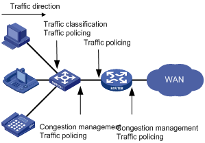
As shown in Figure 1, traffic classification, traffic policing, and congestion management mainly implement the following functions:
· Traffic classification—Uses certain match criteria to assign packets with the same characteristics to a class. Based on classes, you can provide differentiated services.
· Traffic policing—Polices flows entering or leaving a device, and imposes penalties on traffic flows that exceed the preset threshold to prevent aggressive use of network resources. You can apply traffic policing to both incoming and outgoing traffic of a port.
· Congestion management—Provides a resource scheduling policy to determine the packet forwarding sequence when congestion occurs. Congestion management usually applies to the outgoing traffic of a port.
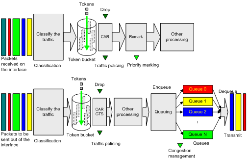
QoS processing flow in a device
Figure 2 briefly describes how the QoS module processes traffic:
1. Traffic classifier identifies and classifies traffic for subsequent QoS actions.
2. The QoS module takes various QoS actions on classified traffic as configured, depending on the traffic processing phase and network status. For example, you can configure the QoS module to perform traffic policing for incoming traffic, and perform congestion management when congestion occurs.
QoS configuration approaches
You can configure QoS by using the following approaches:
Some features support both approaches, but some support only one. For example, you can configure traffic policing by using either the MQC approach or non-MQC approach, and you can configure the rate limit by using the non-MQC approach only.
MQC approach
In the modular QoS configuration (MQC) approach, you configure QoS service parameters by using QoS policies. A QoS policy defines the shaping, policing, or other QoS actions to take on different classes of traffic. It is a set of class-behavior associations.
A class is a set of match criteria for identifying traffic, and it uses the AND or OR operator:
· If the operator is AND, a packet must match all the criteria to match the class.
· If the operator is OR, a packet matches the class if it matches any of the criteria in the class.
A traffic behavior defines a set of QoS actions to take on packets, such as priority marking and redirect.
By associating a traffic behavior with a class in a QoS policy, you apply the specific set of QoS actions to the class of traffic.
Non-MQC approach
In the non-MQC approach, you configure QoS service parameters without using a QoS policy. For example, you can use the rate limit feature to set a rate limit on an interface without using a QoS policy.
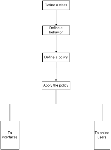
Configuring a QoS policy
Figure 3 shows how to configure a QoS policy.
Figure 3 QoS policy configuration procedure
Defining a class
|
Step |
Command |
Remarks |
|
1. Enter system view. |
system-view |
N/A |
|
2. Create a class and enter class view. |
traffic classifier classifier-name [ operator { and | or } ] |
By default, the operator of a class is AND. The operator of a class can be AND or OR. · AND—A packet is assigned to a class only when the packet matches all the criteria in the class. · OR—A packet is assigned to a class if it matches any of the criteria in the class. |
|
3. Configure match criteria. |
if-match match-criteria |
For more information, see the if-match command in ACL and QoS Command Reference. |
Defining a traffic behavior
A traffic behavior is a set of QoS actions (such as traffic filtering, shaping, policing, and priority marking) to take on a class of traffic.
To define a traffic behavior:
|
Step |
Command |
Remarks |
|
1. Enter system view. |
system-view |
N/A |
|
2. Create a traffic behavior and enter traffic behavior view |
traffic behavior behavior-name |
N/A |
|
3. Configure actions in the traffic behavior. |
N/A |
See the subsequent chapters, depending on the purpose of the traffic behavior: traffic filtering, priority marking, and so on. |
Defining a policy
You associate a behavior with a class in a QoS policy to perform the actions defined in the behavior for the class of packets.
In a QoS that uses ACLs as match criteria, the process for the permit and deny actions in ACLs vary by device. For more information, see About the H3C Access Controllers Command References.
To associate a class with a behavior in a policy:
|
Step |
Command |
Remarks |
|
1. Enter system view. |
system-view |
N/A |
|
2. Create a policy and enter policy view. |
qos policy policy-name |
N/A |
|
3. Associate a class with a behavior in the policy. |
classifier classifier-name behavior behavior-name |
Repeat this step to create more class-behavior associations. |
Applying the QoS policy
You can apply a QoS policy to the following destinations:
· An interface—The policy takes effect on the traffic sent or received on the interface.
· A user profile—The policy takes effect on the traffic sent or received by the online users of the user profile.
You can modify classes, behaviors, and class-behavior associations in a QoS policy even after it is applied. If a class references an ACL for traffic classification, you can delete or modify the ACL (such as add rules to, delete rules from, and modify rules of the ACL).
Applying the QoS policy to an interface
A policy can be applied to multiple interfaces, but only one policy can be applied in one direction (inbound or outbound) of an interface.
The QoS policy applied to the outgoing traffic on an interface does not regulate local packets, which are critical protocol packets sent by the local system for operation maintenance. The most common local packets include link maintenance and SSH packets.
To apply the QoS policy to an interface:
|
Step |
Command |
Remarks |
|
1. Enter system view. |
system-view |
N/A |
|
2. Enter interface view or port group view. |
· Enter interface view: · Enter port group view: |
Settings in interface view take effect on the current interface. Settings in port group view take effect on all ports in the port group. |
|
3. Apply the policy to the interface or port group. |
qos apply policy policy-name { inbound | outbound } |
N/A |
Applying the QoS policy to online users
You can apply a QoS policy to multiple online users. In one direction of each online user, only one policy can be applied. To modify a QoS policy already applied in a certain direction, remove the QoS policy application first.
When you apply the QoS policy to online users, follow these guidelines:
· You can only edit or remove the configurations in a disabled user profile. Disabling a user profile logs out the users that are using the user profile.
· The QoS policy applied to a user profile supports only the remark and filter actions.
· 802.1X, Portal, and MAC authentication methods are supported for online users. The following devices and cards also support PPP authentication:
? EWPXM2WCMD0.
? EWPXM3WCMD0.
? LSQM1WCMD0.
? LSRM1WCM3A1.
? LSUM3WCMD0.
? WAC360.
? WAC361.
? WX2540E.
? WX6103 with EWPX1WCMD0 MPUs installed.
To apply the QoS policy to online users:
|
Step |
Command |
Remarks |
|
1. Enter system view. |
system-view |
N/A |
|
2. Enter user profile view. |
user-profile profile-name |
The configuration made in user profile view takes effect when the user profile is activated and the users of the user profile are online. For more information about user profiles, see Security Configuration Guide. |
|
3. Apply the QoS policy. |
qos apply policy policy-name { inbound | outbound } |
Use the inbound keyword to apply the QoS policy to the incoming traffic of the device (traffic sent by the online users). Use the outbound keyword to apply the QoS policy to the outgoing traffic (traffic received by the online users). |
|
4. Return to system view. |
quit |
N/A |
|
5. Activate the user profile. |
user-profile profile-name enable |
By default, user profiles are inactive. |
Displaying and maintaining QoS policies
|
Task |
Command |
Remarks |
|
Display traffic class configuration. |
display traffic classifier user-defined [ classifier-name ] [ | { begin | exclude | include } regular-expression ] |
Available in any view. |
|
Display traffic behavior configuration. |
display traffic behavior user-defined [ behavior-name ] [ | { begin | exclude | include } regular-expression ] |
Available in any view. |
|
Display QoS policy configuration on a specific interface or all interfaces. |
display qos policy interface [ interface-type interface-number ] [ inbound | outbound ] [ | { begin | exclude | include } regular-expression ] |
Available in any view. |
Configuring priority mapping
Overview
When a packet arrives, depending on your configuration, a device assigns a set of QoS priority parameters to the packet based on either a certain priority field carried in the packet or the port priority of the incoming port. This process is called "priority mapping." During this process, the device can modify the priority of the packet depending on device status. The set of QoS priority parameters decides the scheduling priority and forwarding priority of the packet.
Priority mapping is implemented with priority mapping tables and involves priorities such as 802.11e priority, 802.1p priority, DSCP, EXP, IP precedence, local precedence, and drop precedence.
Introduction to priorities
Priorities fall into the following types: priorities carried in packets, and priorities locally assigned for scheduling only.
The packet-carried priorities include 802.1p priority, DSCP precedence, 802.11e priority, and so on. These priorities have global significance and affect the forwarding priority of packets across the network. For more information about these priorities, see "Appendix B Introduction to packet precedences."
The locally assigned priorities only have local significance. They are assigned by the device for scheduling only. Local precedence is used for queuing. A local precedence value corresponds to an output queue. A packet with higher local precedence is assigned to a higher priority output queue to be preferentially scheduled.
Priority mapping tables
The device provides various types of priority mapping tables, or rather, priority mappings. By looking up a priority mapping table, the device decides which priority value is to assign to a packet for subsequent packet processing.
The default priority mapping tables are available for priority mapping. They are adequate in most cases. If a default priority mapping table cannot meet your requirements, you can modify the priority mapping table as required.
The default priority mapping tables are as follows:
Table 1 The default dot11e-lp priority mapping table
|
802.11e priority |
Local precedence |
|
0 |
2 |
|
1 |
0 |
|
2 |
1 |
|
3 |
3 |
|
4 |
4 |
|
5 |
5 |
|
6 |
6 |
|
7 |
7 |
Table 2 The default dot1p-lp priority mapping table
|
802.1p priority |
Local precedence |
|
0 |
2 |
|
1 |
0 |
|
2 |
1 |
|
3 |
3 |
|
4 |
4 |
|
5 |
5 |
|
6 |
6 |
|
7 |
7 |
Table 3 The default dscp-lp priority mapping table
|
DSCP |
Local precedence |
|
0 to 7 |
0 |
|
8 to 15 |
1 |
|
16 to 23 |
2 |
|
24 to 31 |
3 |
|
32 to 39 |
4 |
|
40 to 47 |
5 |
|
48 to 55 |
6 |
|
56 to 63 |
7 |
Table 4 The default lp-dot1p priority mapping table
|
Local precedence |
802.1p priority |
|
0 |
1 |
|
1 |
2 |
|
2 |
0 |
|
3 |
3 |
|
4 |
4 |
|
5 |
5 |
|
6 |
6 |
|
7 |
7 |
Table 5 The default port priority-to-local priority mapping table
|
Port priority |
Local precedence |
|
0 |
0 |
|
1 |
1 |
|
2 |
2 |
|
3 |
3 |
|
4 |
4 |
|
5 |
5 |
|
6 |
6 |
|
7 |
7 |
Table 6 The default lp-dscp priority mapping table
|
Local precedence |
dscp |
|
0 |
0 |
|
1 |
8 |
|
2 |
16 |
|
3 |
24 |
|
4 |
32 |
|
5 |
40 |
|
6 |
48 |
|
7 |
56 |
Priority mapping configuration tasks
You can configure priority mapping by using any of the following approaches:
· Configuring priority trust mode.
In this approach, you can configure a port to look up a certain priority, 802.1p for example, in incoming packets, in the priority mapping tables. If no packet priority is trusted, the port priority of the incoming port is used.
· Changing port priority.
By default, all ports are assigned the port priority of zero. By changing the port priority of a port, you change the priority of the incoming packets on the port.
Perform these tasks to configure priority mapping:
|
Task |
Remarks |
|
Optional. |
|
|
Configuring a port to trust packet priority for priority mapping |
Optional. |
Configuring a priority mapping table
The device provides the following types of priority mapping table.
Table 7 Priority mapping tables
|
Priority mapping |
Description |
|
dot11e-lp |
802.11e-local mapping table. |
|
dot1p-lp |
802.1p-local mapping table. |
|
dscp-lp |
DSCP-local mapping table. |
|
lp-dot11e |
Local-802.11e mapping table. |
|
lp-dot1p |
Local-802.1p mapping table. |
|
lp-dscp |
Local-DSCP mapping table. |
To configure a priority mapping table:
|
Step |
Command |
Remarks |
|
1. Enter system view. |
system-view |
N/A |
|
2. Enter priority mapping table view. |
qos map-table { dot11e-lp | dot1p-lp | dscp-lp | lp-dot11e | lp-dot1p | lp-dscp } |
N/A |
|
3. Configure the priority mapping table. |
import import-value-list export export-value |
Newly configured mappings overwrite the old ones. |
Configuring a port to trust packet priority for priority mapping
You can configure the device to trust a particular priority field carried in packets for priority mapping on ports or globally.
When you configure the trusted packet priority type on an interface or port group, use the following available keywords:
· dot1p—Uses the 802.1p priority of received packets for mapping.
· dscp—Uses the DSCP precedence of received IP packets for mapping.
· dot11e—Uses the 802.11e priority of received packets for mapping.
To configure the trusted packet priority type on an interface or port group:
|
Step |
Command |
Remarks |
|
1. Enter system view. |
system-view |
N/A |
|
2. Enter interface view or port group view. |
· Enter interface view: · Enter port group view: |
Settings in Ethernet interface view take effect on the Ethernet interface. Settings in WLAN-ESS interface view take effect on all WLAN-DBSS interfaces created on the WLAN-ESS interface. Settings in port group view take effect on all ports in the port group. |
|
3. Configure the trusted packet priority type for the interface. |
qos trust { dot11e | dot1p | dscp } |
The dot11e keyword is only available on WLAN-ESS interfaces. |
If a WLAN-ESS interface in service contains WLAN-DBSS interfaces, you cannot change its trusted packet priority type. To change its trusted packet priority type, you must unbind the bound service template from the WLAN-ESS interface to stop the service the interface is providing.
Changing the port priority of an interface
If an interface does not trust any packet priority, the device uses its port priority to look for the set of priority parameters for the incoming packets. By changing port priority, you can prioritize traffic received on different interfaces.
Configuration restrictions and guidelines
· If a WLAN-ESS interface in service contains WLAN-DBSS interfaces, you cannot modify its priority. To do so, you must log off all online users to stop the service the interface is providing.
· For the uplink data packets, the outer DSCP precedence in the encapsulated tunnel packets is determined according to the 802.11e priority in the incoming WLAN packets. For the data packets encapsulated in the tunnel from an AC to an AP, if the WLAN-ESS interface is configured with the qos priority command and the wired interface is configured to trust the DSCP values of incoming packets, the DSCP precedence is obtained from the lp-dscp mapping table based on the local precedence of packets, and is assigned to the packets. The CAPWAP control packets are always assigned the highest DSCP precedence, which is 56.
Configuration procedure
To change the port priority of an interface:
|
Step |
Command |
Remarks |
|
1. Enter system view. |
system-view |
N/A |
|
2. Enter interface view or port group view. |
· Enter interface view: · Enter port group view: |
Settings in interface view (Ethernet or WLAN-ESS) take effect on the current interface. Settings in port group view take effect on all ports in the port group. |
|
3. Set the port priority of the interface. |
qos priority priority-value |
The default is 0. |
Displaying and maintaining priority mapping
|
Task |
Command |
Remarks |
|
Display priority mapping table configuration. |
display qos map-table [ dot11e-lp | dot1p-lp | dscp-lp | lp-dot11e | lp-dot1p | lp-dscp ] [ | { begin | exclude | include } regular-expression ] |
Available in any view. |
|
Display the trusted packet priority type on a port. |
display qos trust interface [ interface-type interface-number ] [ | { begin | exclude | include } regular-expression ] |
Available in any view. |
Priority mapping configuration examples
ACs have either 10 GE or GE interfaces. Table 8 identifies the Ethernet interfaces on different types of ACs.
If the AC is an AC module installed on a switch, make sure the internal Ethernet interface that connects the switch to the AC module has correct settings, including in particular VLAN settings.
Table 8 AC Ethernet interfaces
|
Hardware |
AC Ethernet interfaces |
|
AC modules (installed in a switch) |
|
|
LSQM1WCMD0 LSRM1WCM3A1 LSUM3WCMD0 LSUM1WCME0 |
The internal Ethernet interface that connects the AC module to the switch. |
|
Wireless switches |
|
|
WX3024E WX3010E |
The internal Ethernet interface that connects the AC engine to the switching engine. |
|
ACs |
|
|
WX6103 |
The internal Ethernet interface that connects the main control board to the switching board. |
|
WX5002V2 WX5004 |
Any Ethernet interfaces on the AC. |
|
WX3510E WX3540E |
|
|
WX5510E |
|
|
WX2540E |
Any LAN or WAN interfaces on the AC. |
|
WAC360 WAC361 |
|
|
WX5540E |
The internal Ethernet interface that connects the AC engine to the switching engine. |
Trusted priority type configuration example
Network requirements
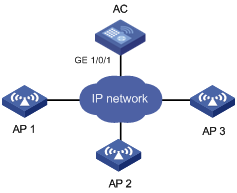
As shown in Figure 4, the AC processes packets for AP 1, AP 2, and AP 3.
Configure the AC to enqueue packets according to their 802.1p priority and use the default priority mapping tables for priority mappings.
Configuration procedure
# Enter system view.
<AC> system-view
# Configure GigabitEthernet 1/0/1 to use the 802.1p priority of incoming packets for priority mapping.
[AC] interface gigabitethernet 1/0/1
[AC-GigabitEthernet1/0/1] qos trust dot1p
# Use the display qos map-table dot1p-lp and display qos map-table lp-dot11e commands to display the default priority mapping tables. According to the default priority mapping tables and the priority values in the captured packets, you can verify the configuration.
[AC] display qos map-table dot1p-lp
MAP-TABLE NAME: dot1p-lp TYPE: pre-define
IMPORT : EXPORT
0 : 2
1 : 0
2 : 1
3 : 3
4 : 4
5 : 5
6 : 6
7 : 7
[AC] display qos map-table lp-dot11e
MAP-TABLE NAME: lp-dot11e TYPE: pre-define
IMPORT : EXPORT
0 : 1
1 : 2
2 : 0
3 : 3
4 : 4
5 : 5
6 : 6
7 : 7
Verifying the configuration
Use a PC to send flows with different priorities to the wireless clients connected to the three APs. After these packets enter the AC, their priorities are mapped to different priorities. You can determine the 802.11e priority of each flow by capturing the packets sent out GigabitEthernet 1/0/1 to different APs.
Port priority configuration example
Network requirements
As shown in Figure 5, the AC processes the packets of AP 1, AP 2, and AP 3. Configure the AC to make sure that:
· Incoming packets are assigned local precedence values through priority mapping based on the port priority of receiving ports.
· The default priority mapping tables of the AC are used.
· The wireless interface of AP 1 is WLAN-ESS 1, that of AP 2 is WLAN-ESS 2, and that of AP 3 is WLAN-ESS 3.
Configuration procedure
For information about associating APs with the AC, see the WLAN access configuration example in "Configuring WLAN access."
# Enter system view.
<AC> system-view
# Set the port priority to 1 for interface WLAN-ESS 1.
[AC] interface wlan-ess 1
[AC-WLAN-ESS1] qos priority 1
[AC-WLAN-ESS1] quit
# Configure service template 1.
[AC] wlan service-template 1 clear
[AC-wlan-st-1] ssid office1
[AC-wlan-st-1] bind wlan-ess 1
# Enable service template 1.
[AC-wlan-st-1] service-template enable
[AC-wlan-st-1] quit
# Set the port priority to 3 for interface WLAN-ESS 2.
[AC] interface wlan-ess 2
[AC-WLAN-ESS2] qos priority 3
[AC-WLAN-ESS2] quit
# Configure service template 2.
[AC] wlan service-template 2 clear
[AC-wlan-st-2] ssid office2
[AC-wlan-st-2] bind wlan-ess 2
# Enable service template 2.
[AC-wlan-st-2] service-template enable
[AC-wlan-st-2] quit
# Set the port priority to 5 for interface WLAN-ESS 3.
[AC] interface wlan-ess 3
[AC-WLAN-ESS3] qos priority 5
[AC-WLAN-ESS3] quit
# Configure service template 3.
[AC] wlan service-template 3 clear
[AC-wlan-st-3] ssid office3
[AC-wlan-st-3] bind wlan-ess 3
# Enable service template 3.
[AC-wlan-st-3] service-template enable
[AC-wlan-st-3] quit
Verifying the configuration
Connect a client to each AP. Ping the same PC from the three wireless clients. Capture the packets sent out interface GigabitEthernet 1/0/1 of the AC, and you can determine the mapped priority of the packets from each wireless client.
Configuring rate limiting
Overview
Rate limiting helps assign network resources, such as assign bandwidth, and increases network performance and user satisfaction. For example, you can configure a flow to use only the resources committed to it in a certain time range. This avoids network congestion caused by burst traffic.
Rate limiting limits the traffic rate and resource usage according to traffic specifications and uses token buckets to evaluate traffic specifications. Once a particular flow exceeds its specifications, such as assigned bandwidth, the flow is rate limited to make sure it is under the specifications.
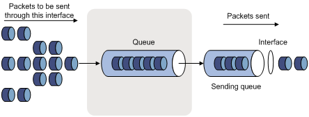
When rate limiting is configured on an interface, all packets to be sent through the interface are handled by the token bucket. When a packet arrives, the packet is forwarded if the token bucket has sufficient tokens. Otherwise, the packet is put into a QoS queue for congestion management. In this way, the traffic passing the physical interface is controlled.
Figure 6 Rate limiting implementation
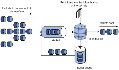
The token bucket mechanism limits traffic rate when accommodating bursts. It allows bursty traffic to be transmitted if enough tokens are available. If tokens are scarce, packets cannot be transmitted until efficient tokens are generated in the token bucket. It restricts the traffic rate to the rate for generating tokens.
Rate limiting controls the total rate of all packets on a physical interface.
Traffic evaluation and token buckets
Token bucket features
A token bucket is analogous to a container that holds a certain number of tokens. Each token represents a certain forwarding capacity. The system puts tokens into the bucket at a constant rate. When the token bucket is full, the extra tokens cause the token bucket to overflow.
Evaluating traffic with the token bucket
A token bucket mechanism evaluates traffic by looking at the number of tokens in the bucket. If the number of tokens in the bucket is enough for forwarding the packets, the traffic conforms to the specification, and is called "conforming traffic." Otherwise, the traffic does not conform to the specification, and is called "excess traffic."
A token bucket has the following configurable parameters:
· Mean rate at which tokens are put into the bucket—Permitted average rate of traffic. It is usually set to the committed information rate (CIR).
· Burst size or the capacity of the token bucket—Maximum traffic size permitted in each burst. It is usually set to the committed burst size (CBS). The set burst size must be greater than the maximum packet size.
Each arriving packet is evaluated. In each evaluation, if the number of tokens in the bucket is enough, the traffic conforms to the specification and the tokens for forwarding the packet are taken away. If the number of tokens in the bucket is not enough, the traffic is excessive.
Configuring rate limiting
The rate limit of a physical interface specifies the maximum rate of outgoing packets.
To configure rate limiting:
|
Step |
Command |
Remarks |
|
1. Enter system view. |
system-view |
N/A |
|
2. Enter interface view or port group view. |
· Enter interface view: · Enter port group view: |
Settings in interface view take effect on the current interface. Settings in port group view take effect on all ports in the port group. |
|
3. Configure rate limiting for the interface or port group. |
qos lr outbound cir committed-information-rate [ cbs committed-burst-size ] |
N/A |
Displaying and maintaining rate limiting
|
Task |
Command |
Remarks |
|
Display rate limiting configuration on interfaces. |
display qos lr interface [ interface-type interface-number ] [ | { begin | exclude | include } regular-expression ] |
Available in any view. |
Rate limiting configuration example
ACs have either 10 GE or GE interfaces. Table 8 identifies the Ethernet interfaces on different types of ACs.
If the AC is an AC module installed on a switch, make sure the internal Ethernet interface that connects the switch to the AC module has correct settings, including in particular VLAN settings.
Network requirements
As shown in Figure 7, limit the rate for the AP to access the Internet to 1000 kbps.
Configuration procedure
# Configure rate limiting on GigabitEthernet 1/0/1.
[AC] interface gigabitethernet1/0/1
[AC-GigabitEthernet1/0/1] qos lr outbound cir 1000
[AC-GigabitEthernet1/0/1] quit
Configuring congestion management
Overview
Causes, impacts, and countermeasures of congestion
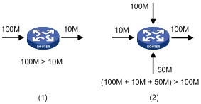
Congestion occurs on a link or node when traffic size exceeds the processing capability of the link or node. It is typical of a statistical multiplexing network, and can be caused by link failures, insufficient resources, and various other causes. Figure 8 shows some common congestion scenarios.
Figure 8 Traffic congestion causes
Congestion can bring the following negative results:
· Increased delay and jitter during packet transmission.
· Decreased network throughput and resource use efficiency.
· Network resource (memory, in particular) exhaustion and system breakdown.
Congestion is unavoidable in switched networks or multiuser application environments. To improve the service performance of your network, take measures to manage and control it.
One major issue that congestion management deals with is defining a resource dispatching policy to prioritize packets for forwarding when congestion occurs.
Congestion management policies
Queuing is a common congestion management technique. It classifies traffic into queues and picks out packets from each queue by using a certain algorithm. Various queuing algorithms are available, and each addresses a particular network traffic problem. Your choice of algorithm significantly affects bandwidth assignment, delay, and jitter.
Congestion management involves queue creating, traffic classification, packet enqueuing, and queue scheduling. Queue scheduling treats packets with different priorities differently to transmit high-priority packets preferentially.
This section briefly describes several common queue-scheduling mechanisms.
FIFO
As shown in Figure 9, the first in first out (FIFO) uses a single queue and does not classify traffic or schedule queues. FIFO delivers packets depending on their arrival order, with the one arriving earlier scheduled first. The only concern of FIFO is queue length, which affects delay and packet loss rate. On a device, resources are assigned to packets depending on their arrival order and load status of the device. The best-effort service model uses FIFO queuing.
FIFO does not address congestion problems. If only one FIFO output/input queue exists on a port, you can hardly ensure timely delivery of mission-critical or delay-sensitive traffic, or smooth traffic jitter. The situation is worsened if malicious traffic is present to occupy bandwidth aggressively. To control congestion and prioritize forwarding of critical traffic, use other queue scheduling mechanisms, where multiple queues can be configured. Within each queue, however, FIFO is still used.
By default, FIFO queuing is used on interfaces.
Priority queuing
Figure 10 Priority queuing (PQ)
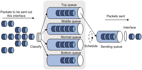
Priority queuing is designed for mission-critical applications. The key feature of mission-critical applications is they require preferential service to reduce the response delay when congestion occurs. Priority queuing can flexibly determine the order of forwarding packets by network protocol (for example, IP and IPX), incoming interface, packet length, source/destination address, and so on. Priority queuing classifies packets into four queues: top, middle, normal, and bottom, in descending priority order. By default, packets are assigned to the normal queue. Each of the four queues is a FIFO queue.
Priority queuing schedules the four queues in the descending order of priority. It sends packets in the queue with the highest priority first. When the queue with the highest priority is empty, it sends packets in the queue with the second highest priority. In this way, you can assign the mission-critical packets to the high priority queue to make sure they are always served first. The common service packets are assigned to the low priority queues, and transmitted when the high priority queues are empty.
The disadvantage of priority queuing is that packets in the lower priority queues cannot be transmitted if packets exist in the higher queues for a long time when congestion occurs.
Custom queuing
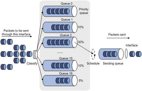
CQ provides 17 queues, numbered from 0 to 16. Queue 0 is a reserved system queue, and queues 1 through 16 are customer queues, as shown in Figure 11. You can define traffic classification rules and assign a percentage of interface bandwidth to each customer queue. By default, packets are assigned to queue 1.
During a cycle of queue scheduling, CQ first empties the system queue. Then, it schedules the 16 queues in a round robin way: it sends a certain number of packets (based on the percentage of interface bandwidth assigned to each queue) out of each queue in the ascending order of queue 1 to queue 16. CQ guarantees normal packets a certain amount of bandwidth, and makes sure mission-critical packets are assigned more bandwidth.
CQ can assign free bandwidth of idle queues to busy queues. Even though it performs round robin queue scheduling, CQ does not assign fixed time slots to the queues. If a queue is empty, CQ immediately moves to the next queue. When a class does not have packets, the bandwidth increases for other classes.
Congestion management technique comparison
Breaking through the single congestion management policy of FIFO for traditional IP devices, the device provides all the congestion management techniques described above to offer powerful QoS capabilities, meeting different QoS requirements of different applications.
Table 9 Congestion management technique comparison
|
Type |
Number of queues |
Advantages |
Disadvantages |
|
FIFO |
1 |
· No need to configure, easy to use. · Easy to operate, low delay. |
· All packets are treated equally. The available bandwidth, delay and drop probability are determined by the arrival order of packets. · No restriction on traffic from connectionless protocols (protocols without any flow control mechanism, UDP, for example), resulting in bandwidth loss for traffic of connection-oriented protocols (TCP, for example). · No delay guarantee for time-sensitive real-time applications, such as VoIP. |
|
PQ |
4 |
Absolute bandwidth and delay guarantees for real-time and mission-critical applications, such as VoIP. |
· Need to configure, low processing speed. · If no restriction is imposed on bandwidth assigned to high-priority packets, low-priority packets may fail to get bandwidth. |
|
CQ |
16 |
· Bandwidth assignment in percentages for different applications. · Bandwidth reassignment to increase bandwidth for each class when packets of certain classes are not present. |
Need to configure, low processing speed. |
If the burst traffic is too heavy, increase the queue length to make queue scheduling more accurate.
Configuring the FIFO queue size
Configuration procedure
To configure the FIFO queue size:
|
Step |
Command |
Remarks |
|
1. Enter system view. |
system-view |
N/A |
|
2. Enter interface view. |
interface interface-type interface-number |
N/A |
|
3. Configure the FIFO queue size. |
qos fifo queue-length queue-length |
The default FIFO queue size is 75. |
Configuration example
# Set the FIFO queue size to 100.
<Sysname> system-view
[Sysname] interface gigabitethernet 1/0/1
[Sysname-GigabitEthernet1/0/1] qos fifo queue-length 100
Configuring PQ
You can define multiple rules for a priority queue list (PQL), and apply the list to an interface. When a packet arrives at the interface, the system matches the packet with each rule in the order configured. If a match is found, the packet is assigned to the queue, and the match procedure is complete. If the packet cannot match any rule, the packet is assigned to the default queue normal.
Configuration procedure
You can configure PQ by applying a PQ list to an interface. For an interface, the latest applied PQ list overwrites the previous one.
To configure PQ:
|
Step |
Command |
Remarks |
|
1. Enter system view. |
system-view |
N/A |
|
2. Configure a PQ list. |
· qos pql pql-index protocol ip [ queue-key key-value ] queue { bottom | middle | normal | top } · qos pql pql-index local-precedence local-precedence-value queue { bottom | middle | normal | top } |
Use a command as needed. |
|
3. Specify the default queue for the PQ list. |
qos pql pql-index default-queue { bottom | middle | normal | top } |
Optional. This command specifies the queue to which unmatched packets are assigned. The default setting is normal. |
|
4. Set the queue size. |
qos pql pql-index queue { bottom | middle | normal | top } queue-length queue-length |
Optional. |
|
5. Enter interface view. |
interface interface-type interface-number |
N/A |
|
6. Apply the PQ list to the interface. |
qos pq pql pql-index |
By default, FIFO applies. |
|
7. Display PQ list configuration information. |
display qos pq interface [ interface-type interface-number ] [ | { begin | exclude | include } regular-expression ] |
Optional. Available in any view. |
|
8. Display the contents of the specific PQ list or all the PQ lists. |
display qos pql [ pql-number ] [ | { begin | exclude | include } regular-expression ] |
Optional. Available in any view. |
PQ configuration example
ACs have either 10 GE or GE interfaces. Table 8 identifies the Ethernet interfaces on different types of ACs.
If the AC is an AC module installed on a switch, make sure the internal Ethernet interface that connects the switch to the AC module has correct settings, including in particular VLAN settings.
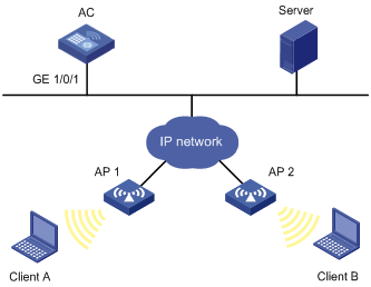
Network requirements
As shown in Figure 12, Client A and Client B get data from Server through the wireless controller AC. When the traffic from the Server to clients enters the AC, the traffic is assigned local precedence 5 through priority mapping. Configure the AC to preferentially process traffic with local precedence 5.
Configuration procedure
# Enter system view.
<AC> system-view
# Configure PQ list 1 to assign packets that match no criteria to the middle queue.
[AC] qos pql 1 default-queue middle
# Configure PQ list 1 to assign packets with local precedence value 5 to the top queue.
[AC] qos pql 1 local-precedence 5 queue top
# Set the maximum length to 1000 for the middle queue in PQ list 1.
[AC] qos pql 1 queue middle queue-length 1000
# Apply PQ list 1 to interface GigabitEthernet 1/0/1 and configure interface GigabitEthernet 1/0/1 to use the 802.1p priority of the received packets for priority mapping.
[AC] interface gigabitethernet1/0/1
[AC-GigabitEthernet1/0/1] qos pq pql 1
[AC-GigabitEthernet1/0/1] qos trust dot1p
Configuring CQ
You can configure a CQ list that contains up to 16 queues (1-16), with each queue including the match criteria for packets to enter the queue, the length of the queue, and the bytes sent from the queue during a cycle of round robin queue scheduling. Only one CQ list can be applied to an interface.
Configuration procedure
To configure CQ:
|
Step |
Command |
Remarks |
|
1. Enter system view. |
system-view |
N/A |
|
2. Configure a CQ list. |
· qos cql cql-index protocol ip [ queue-key key-value ] queue queue-number · qos cql cql-index local-precedence local-precedence-value queue queue-number |
Optional. Use a command as needed. |
|
3. Specify the default queue. |
qos cql cql-index default-queue queue-number |
Optional. This command specifies the queue to which unmatched packets are assigned. |
|
4. Set the length of a queue. |
qos cql cql-index queue queue-number queue-length queue-length |
Optional. |
|
5. Configure the bytes sent from a queue during a cycle of round robin queue scheduling. |
qos cql cql-index queue queue-number serving byte-count |
Optional. |
|
6. Enter interface view. |
interface interface-type interface-number |
N/A |
|
7. Apply the CQ list to the interface. |
qos cq cql cql-index |
By default, FIFO applies. |
|
8. Display interface CQ list configuration information. |
display qos cq interface [ interface-type interface-number ] [ | { begin | exclude | include } regular-expression ] |
Optional. Available in any view. |
|
9. Display information about CQ lists. |
display qos cql [ cql-index ] [ | { begin | exclude | include } regular-expression ] |
Optional. Available in any view. |
CQ configuration example
ACs have either 10 GE or GE interfaces. Table 8 identifies the Ethernet interfaces on different types of ACs.
If the AC is an AC module installed on a switch, make sure the internal Ethernet interface that connects the switch to the AC module has correct settings, including in particular VLAN settings.
Network requirements
Configure CQ on interface GigabitEthernet 1/0/1 to assign the incoming packets with local precedence 4 to queue 1, and specify queue 1 to send 1635000 bytes during a cycle of round robin queue scheduling.
Configuration procedure
# Enter system view.
<Sysname> system-view
# Configure queue 1 as the default queue in CQ list 1.
[Sysname]qos cql 1 default-queue 1
# Configure CQ list 1 to assign packets with local precedence value 4 to queue 1.
[Sysname]qos cql 1 local-precedence 4 queue 1
# Set the maximum length of queue 1 to 1000 in CQ list 1.
[Sysname]qos cql 1 queue 1 queue-length 1000
# Configure queue 1 to send 1635000 bytes in a cycle of round robin queue scheduling in CQ list 1.
[Sysname]qos cql 1 queue 1 serving 1635000
# Apply CQ list 1 to interface GigabitEthernet1/0/1, and configure interface GigabitEthernet 1/0/1 to use the 802.1p priority of received packets for priority mapping.
[Sysname]interface GigabitEthernet1/0/1
[Sysname-GigabitEthernet1/0/1]qos cq cql 1
[Sysname-GigabitEthernet1/0/1]qos trust dot1p
Configuring traffic filtering
You can filter in or filter out a class of traffic by associating the class with a traffic filtering action. For example, you can filter packets sourced from a specific IP address according to network status.
Configuration procedure
To configure traffic filtering:
|
Step |
Command |
Remarks |
|
1. Enter system view. |
system-view |
N/A |
|
2. Create a class and enter class view. |
traffic classifier classifier-name [ operator { and | or } ] |
N/A |
|
3. Configure match criteria. |
if-match match-criteria |
N/A |
|
4. Return to system view. |
quit |
N/A |
|
5. Create a behavior and enter behavior view. |
traffic behavior behavior-name |
N/A |
|
6. Configure the traffic filtering action. |
filter { deny | permit } |
· deny—Drops packets. · permit—Permits packets to pass through. |
|
7. Return to system view. |
quit |
N/A |
|
8. Create a policy and enter policy view. |
qos policy policy-name |
N/A |
|
9. Associate the class with the traffic behavior in the QoS policy. |
classifier classifier-name behavior behavior-name |
N/A |
|
10. Return to system view. |
quit |
N/A |
|
11. Apply the QoS policy. |
Choose one of the application destinations as needed. |
|
|
12. Display the traffic filtering configuration. |
display traffic behavior user-defined [ behavior-name ] [ | { begin | exclude | include } regular-expression ] |
Optional. Available in any view. |
If a traffic behavior has the filter deny action, all the other actions in the traffic behavior do not take effect.
Traffic filtering configuration example
ACs have either 10 GE or GE interfaces. Table 8 identifies the Ethernet interfaces on different types of ACs.
If the AC is an AC module installed on a switch, make sure the internal Ethernet interface that connects the switch to the AC module has correct settings, including in particular VLAN settings.
Network requirements
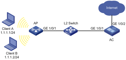
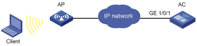
As shown in Figure 13, Client is connected to AC through AP.
Configure traffic filtering to filter the packets with source port 21 that GigabitEthernet 1/0/1 receives.
Configuration procedure
# Create advanced ACL 3000, and configure a rule to match packets whose source port number is not 21.
<AC> system-view
[AC] acl number 3000
[AC-acl-adv-3000] rule 0 permit tcp source-port eq 21
[AC-acl-adv-3000] quit
# Create a class named classifier_1, and use ACL 3000 as the match criterion in the class.
[AC] traffic classifier classifier_1
[AC-classifier-classifier_1] if-match acl 3000
[AC-classifier-classifier_1] quit
# Create a behavior named behavior_1, and configure the traffic filtering action to drop packets.
[AC] traffic behavior behavior_1
[AC-behavior-behavior_1] filter deny
[AC-behavior-behavior_1] quit
# Create a policy named policy_1, and associate class classifier_1 with behavior behavior_1 in the policy.
[AC] qos policy policy_1
[AC-qospolicy-policy_1] classifier classifier_1 behavior behavior_1
[AC-qospolicy-policy_1] quit
# Apply the policy named policy_1 to the incoming traffic of GigabitEthernet 1/0/1.
[AC] interface gigabitethernet 1/0/1
[AC-GigabitEthernet1/0/1] qos apply policy policy_1 inbound
Configuring priority marking
Priority marking sets the priority fields or flag bits of packets to modify the priority of traffic. For example, you can use priority marking to set IP precedence or DSCP for a class of IP traffic to change its transmission priority in the network.
Configuration procedure
To configure priority marking:
|
Step |
Command |
Remarks |
|
1. Enter system view. |
system-view |
N/A |
|
2. Create a class and enter class view. |
traffic classifier classifier-name [ operator { and | or } ] |
N/A |
|
3. Configure match criteria. |
if-match match-criteria |
N/A |
|
4. Return to system view. |
quit |
N/A |
|
5. Create a behavior and enter behavior view. |
traffic behavior behavior-name |
N/A |
|
6. Set the 802.1p priority for packets. |
remark dot1p 8021p |
Optional. |
|
7. Set the local precedence for packets. |
remark local-precedence local-precedence |
Optional. |
|
8. Return to system view. |
quit |
N/A |
|
9. Create a policy and enter policy view. |
qos policy policy-name |
N/A |
|
10. Associate the class with the traffic behavior in the QoS policy. |
classifier classifier-name behavior behavior-name |
N/A |
|
11. Return to system view. |
quit |
N/A |
|
12. Apply the QoS policy. |
Choose one of the application destinations as needed. |
|
|
13. Display the priority marking configuration. |
display traffic behavior user-defined [ behavior-name ] [ | { begin | exclude | include } regular-expression ] |
Optional. Available in any view. |
Priority marking configuration example
ACs have either 10 GE or GE interfaces. Table 8 identifies the Ethernet interfaces on different types of ACs.
If the AC is an AC module installed on a switch, make sure the internal Ethernet interface that connects the switch to the AC module has correct settings, including in particular VLAN settings.
Network requirements
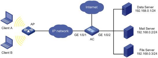
As shown in Figure 14, the enterprise network of a company interconnects hosts with servers through the AC. The network is described as follows:
· Client A and Client B are connected to service template 1 of the AC through the AP. Service template 1 is bound with interface WLAN-ESS1.
· The data server, mail server, and file server are connected to GigabitEthernet 1/0/2 of the AC.
Configure priority marking on the AC to meet the following requirements:
|
Traffic source |
Destination |
Processing priority |
|
Client A, B |
Data server |
High |
|
Client A, B |
Mail server |
Medium |
|
Client A, B |
File server |
Low |
Configuration procedure
# Create advanced ACL 3000, and configure a rule to match packets with destination IP address 192.168.0.1.
<AC> system-view
[AC] acl number 3000
[AC-acl-adv-3000] rule permit ip destination 192.168.0.1 0
[AC-acl-adv-3000] quit
# Create advanced ACL 3001, and configure a rule to match packets with destination IP address 192.168.0.2.
[AC] acl number 3001
[AC-acl-adv-3001] rule permit ip destination 192.168.0.2 0
[AC-acl-adv-3001] quit
# Create advanced ACL 3002, and configure a rule to match packets with destination IP address 192.168.0.3.
[AC] acl number 3002
[AC-acl-adv-3002] rule permit ip destination 192.168.0.3 0
[AC-acl-adv-3002] quit
# Create a class named classifier_dbserver, and use ACL 3000 as the match criterion in the class.
[AC] traffic classifier classifier_dbserver
[AC-classifier-classifier_dbserver] if-match acl 3000
[AC-classifier-classifier_dbserver] quit
# Create a class named classifier_mserver, and use ACL 3001 as the match criterion in the class.
[AC] traffic classifier classifier_mserver
[AC-classifier-classifier_mserver] if-match acl 3001
[AC-classifier-classifier_mserver] quit
# Create a class named classifier_fserver, and use ACL 3002 as the match criterion in the class.
[AC] traffic classifier classifier_fserver
[AC-classifier-classifier_fserver] if-match acl 3002
[AC-classifier-classifier_fserver] quit
# Create a behavior named behavior_dbserver, and configure the action of setting the local precedence value to 4.
[AC] traffic behavior behavior_dbserver
[AC-behavior-behavior_dbserver] remark local-precedence 4
[AC-behavior-behavior_dbserver] quit
# Create a behavior named behavior_mserver, and configure the action of setting the local precedence value to 3.
[AC] traffic behavior behavior_mserver
[AC-behavior-behavior_mserver] remark local-precedence 3
[AC-behavior-behavior_mserver] quit
# Create a behavior named behavior_fserver, and configure the action of setting the local precedence value to 2.
[AC] traffic behavior behavior_fserver
[AC-behavior-behavior_fserver] remark local-precedence 2
[AC-behavior-behavior_fserver] quit
# Create a policy named policy_server, and associate classes with behaviors in the policy.
[AC] qos policy policy_server
[AC-qospolicy-policy_server] classifier classifier_dbserver behavior behavior_dbserver
[AC-qospolicy-policy_server] classifier classifier_mserver behavior behavior_mserver
[AC-qospolicy-policy_server] classifier classifier_fserver behavior behavior_fserver
[AC-qospolicy-policy_server] quit
# Apply the policy named policy_server to the incoming traffic of interface WLAN-ESS1.
[AC] interface wlan-ess 1
[AC-WLAN-ESS1] qos apply policy policy_server inbound
[AC-WLAN-ESS1] quit
Appendix
Appendix A Acronyms
Table 10 Acronyms
|
Acronym |
Full spelling |
|
AF |
Assured Forwarding |
|
BE |
Best Effort |
|
CBS |
Committed Burst Size |
|
CIR |
Committed Information Rate |
|
CQ |
Custom Queuing |
|
DiffServ |
Differentiated Service |
|
DSCP |
Differentiated Services Code Point |
|
EF |
Expedited Forwarding |
|
FIFO |
First in First out |
|
IntServ |
Integrated Service |
|
ISP |
Internet Service Provider |
|
PQ |
Priority Queuing |
|
QoS |
Quality of Service |
|
RSVP |
Resource Reservation Protocol |
|
ToS |
Type of Service |
Appendix B Introduction to packet precedences
IP precedence and DSCP values
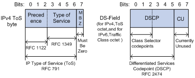
As shown in Figure 15, the ToS field in the IPv4 header contains eight bits, where the first three bits (0 to 2) represent IP precedence from 0 to 7. The Traffic Classes field in the IPv6 header contains eight bits, where the first three bits (0 to 2) represent IP precedence from 0 to 7. According to RFC 2474, the ToS field in the IPv4 header or the Traffic Classes field in the IPv6 header is redefined as the DS field, where a DSCP value is represented by the first six bits (0 to 5) and is in the range 0 to 63. The remaining two bits (6 and 7) are reserved.
Table 11 IP precedence
|
IP precedence (decimal) |
IP precedence (binary) |
Description |
|
0 |
000 |
Routine |
|
1 |
001 |
priority |
|
2 |
010 |
immediate |
|
3 |
011 |
flash |
|
4 |
100 |
flash-override |
|
5 |
101 |
critical |
|
6 |
110 |
internet |
|
7 |
111 |
network |
Table 12 DSCP values
|
DSCP value (decimal) |
DSCP value (binary) |
Description |
|
46 |
101110 |
ef |
|
10 |
001010 |
af11 |
|
12 |
001100 |
af12 |
|
14 |
001110 |
af13 |
|
18 |
010010 |
af21 |
|
20 |
010100 |
af22 |
|
22 |
010110 |
af23 |
|
26 |
011010 |
af31 |
|
28 |
011100 |
af32 |
|
30 |
011110 |
af33 |
|
34 |
100010 |
af41 |
|
36 |
100100 |
af42 |
|
38 |
100110 |
af43 |
|
8 |
001000 |
cs1 |
|
16 |
010000 |
cs2 |
|
24 |
011000 |
cs3 |
|
32 |
100000 |
cs4 |
|
40 |
101000 |
cs5 |
|
48 |
110000 |
cs6 |
|
56 |
111000 |
cs7 |
|
0 |
000000 |
be (default) |
802.1p priority
802.1p priority lies in the Layer 2 header and applies to occasions where Layer 3 header analysis is not needed and QoS must be assured at Layer 2.
Figure 16 An Ethernet frame with an 802.1Q tag header
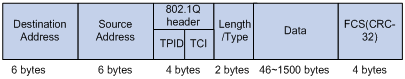
As shown in Figure 16, the four-byte 802.1Q tag header consists of the TPID (two bytes in length), whose value is 0x8100, and the TCI (two bytes in length). Figure 17 shows the format of the 802.1Q tag header. The Priority field in the 802.1Q tag header is called the "802.1p priority," because its use is defined in IEEE 802.1p. Table 13 shows the values for 802.1p priority.
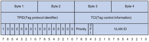
Table 13 Description on 802.1p priority
|
802.1p priority (decimal) |
802.1p priority (binary) |
Description |
|
0 |
000 |
best-effort |
|
1 |
001 |
background |
|
2 |
010 |
spare |
|
3 |
011 |
excellent-effort |
|
4 |
100 |
controlled-load |
|
5 |
101 |
video |
|
6 |
110 |
voice |
|
7 |
111 |
network-management |
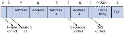
802.11e priority
To provide QoS services on WLAN, the 802.11e standard was developed. IEEE 802.11e is a MAC-layer enhancement to IEEE 802.11. IEEE 802.11e adds a 2-byte QoS Control field to the 802.11e MAC frame header. Three bits of the QoS control field represents the 802.11e priority, which is in the range of 0 to 7.
Figure 18 802.11e frame structure