- Table of Contents
-
- 03-Layer 2-LAN Switching Configuration Guide
- 00-Preface
- 01-Ethernet interface configuration
- 02-Loopback, null, and inloopback interface configuration
- 03-Bulk interface configuration
- 04-MAC address table configuration
- 05-Ethernet link aggregation configuration
- 06-Port isolation configuration
- 07-Spanning tree configuration
- 08-Loop detection configuration
- 09-VLAN configuration
- 10-MVRP configuration
- 11-QinQ configuration
- 12-VLAN mapping configuration
- 13-LLDP configuration
- 14-Service loopback group configuration
- Related Documents
-
| Title | Size | Download |
|---|---|---|
| 09-VLAN configuration | 549.88 KB |
Contents
Configuring basic VLAN settings
Configuring basic settings of a VLAN interface
Assigning an access port to a VLAN
Assigning a trunk port to a VLAN
Assigning a hybrid port to a VLAN
Configuration restrictions and guidelines
Configuring static MAC-based VLAN assignment
Configuring dynamic MAC-based VLAN assignment
Configuring server-assigned MAC-based VLAN
Configuring IP subnet-based VLANs
Configuring protocol-based VLANs
Displaying and maintaining VLANs
Port-based VLAN configuration example
MAC-based VLAN configuration example
IP subnet-based VLAN configuration example
Protocol-based VLAN configuration example
Super VLAN configuration task list
Configuring a super VLAN interface
Displaying and maintaining super VLANs
Super VLAN configuration example
Configuration restrictions and guidelines
Displaying and maintaining the private VLAN
Private VLAN configuration examples
Promiscuous port configuration example
Trunk promiscuous port configuration example
Trunk promiscuous and trunk secondary port configuration example
Secondary VLAN Layer 3 communication configuration example
Methods of identifying IP phones
Identifying IP phones through OUI addresses
Automatically identifying IP phones through LLDP
Advertising the voice VLAN information to IP phones
Connecting the host and the IP phone in series
Connecting the IP phone to the device
Configuring a voice VLAN on a port
Security mode and normal mode of voice VLANs
Configuring the QoS priority settings for voice traffic
Configuring a port to operate in automatic voice VLAN assignment mode
Configuring a port to operate in manual voice VLAN assignment mode
Enabling LLDP for automatic IP phone discovery
Configuration restrictions and guidelines
Configuring LLDP or CDP to advertise a voice VLAN
Dynamically advertising an authorization VLAN through LLDP or CDP
Displaying and maintaining voice VLANs
Voice VLAN configuration examples
Configuring VLANs
Overview
Ethernet is a family of shared-media LAN technologies based on the CSMA/CD mechanism. An Ethernet LAN is both a collision domain and a broadcast domain. Because the medium is shared, collisions and broadcasts are common in an Ethernet LAN. Typically, bridges and Layer 2 switches can reduce collisions in an Ethernet LAN. To confine broadcasts, a Layer 2 switch must use the Virtual Local Area Network (VLAN) technology.
VLANs enable a Layer 2 switch to break a LAN down into smaller broadcast domains, as shown in Figure 1.
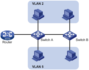
A VLAN is logically divided on an organizational basis rather than on a physical basis. For example, you can assign all workstations and servers used by a particular workgroup to the same VLAN, regardless of their physical locations. Hosts in the same VLAN can directly communicate with one another. You need a router or a Layer 3 switch for hosts in different VLANs to communicate with one another.
All these VLAN features reduce bandwidth waste, improve LAN security, and enable flexible virtual group creation.
VLAN frame encapsulation
To identify Ethernet frames from different VLANs, IEEE 802.1Q inserts a four-byte VLAN tag between the destination and source MAC address (DA&SA) field and Type field.
Figure 2 VLAN tag placement and format
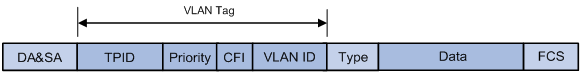
A VLAN tag includes the following fields:
· TPID—16-bit tag protocol identifier that indicates whether a frame is VLAN-tagged. By default, the TPID value 0x8100 identifies a VLAN-tagged frame. A device vendor can set TPID to different values. For compatibility with a neighbor device, configure the TPID value on the device to be the same as the neighbor device.
· Priority—3-bit long, identifies the 802.1p priority of the frame. For more information, see ACL and QoS Configuration Guide.
· CFI—1-bit long canonical format indicator that indicates whether the MAC addresses are encapsulated in the standard format when packets are transmitted across different media. Available values include:
¡ 0 (default)—The MAC addresses are encapsulated in the standard format.
¡ 1—The MAC addresses are encapsulated in a nonstandard format.
This field is always set to 0 for Ethernet.
· VLAN ID—12-bit long, identifies the VLAN to which the frame belongs. The VLAN ID range is 0 to 4095. VLAN IDs 0 and 4095 are reserved, and VLAN IDs 1 to 4094 are user configurable.
The way a network device handles an incoming frame depends on whether the frame has a VLAN-tag and the value of the VLAN tag (if any). For more information, see "Introduction."
Ethernet supports encapsulation formats Ethernet II, 802.3/802.2 LLC, 802.3/802.2 SNAP, and 802.3 raw. The Ethernet II encapsulation format is used here. For information about the VLAN tag fields in other frame encapsulation formats, see related protocols and standards.
For a frame with multiple VLAN tags, the device handles it according to its outer-most VLAN tag and transmits its inner VLAN tags as the payload.
Protocols and standards
IEEE 802.1Q, IEEE Standard for Local and Metropolitan Area Networks: Virtual Bridged Local Area Networks
Configuring basic VLAN settings
|
Step |
Command |
Remarks |
|
1. Enter system view. |
system-view |
N/A |
|
2. (Optional.) Create a VLAN and enter its view, or create a list of VLANs. |
vlan { vlan-id1 [ to vlan-id2 ] | all } |
By default, only the system default VLAN (VLAN 1) exists. |
|
3. Enter VLAN view. |
vlan vlan-id |
To configure a VLAN after you create a list of VLANs, you must perform this step. |
|
4. Configure a name for the VLAN. |
name text |
By default, VLAN names are in the format VLAN vlan-id. For example, the name of VLAN 100 is VLAN 0100 by default. |
|
5. Configure the description of the VLAN. |
description text |
The default setting is VLAN vlan-id, which is the ID of the VLAN. For example, the description of VLAN 100 is VLAN 0100 by default. |
|
|
NOTE: · As the system default VLAN, VLAN 1 cannot be created or deleted. · Before you delete a dynamic VLAN, a VLAN configured with the QoS policy, or a VLAN locked by an application, you must first remove the configuration from the VLAN. |
Configuring basic settings of a VLAN interface
Hosts of different VLANs use VLAN interfaces to communicate at Layer 3. VLAN interfaces are virtual interfaces that do not exist as physical entities on devices. For each VLAN, you can create one VLAN interface and assign an IP address to it. The VLAN interface acts as the gateway of the VLAN to forward packets destined for another IP subnet.
When you configure a VLAN interface, follow these restrictions and guidelines:
· Before you create a VLAN interface for a VLAN, create the VLAN first.
· You cannot create a VLAN interface for a sub-VLAN. For more information about sub-VLANs, see "Configuring super VLANs."
· You cannot create VLAN interfaces for secondary VLANs that have the following characteristics:
¡ Associated with the same primary VLAN.
¡ Enabled with Layer 3 communication in VLAN interface view of the primary VLAN interface.
For more information about secondary VLANs, see "Configuring the private VLAN."
To configure basic settings of a VLAN interface:
|
Step |
Command |
Remarks |
|
1. Enter system view. |
system-view |
N/A |
|
2. Create a VLAN interface and enter VLAN interface view. |
interface vlan-interface vlan-interface-id |
If the VLAN interface already exists, you enter its view directly. By default, no VLAN interface is created. |
|
3. Assign an IP address to the VLAN interface. |
ip address ip-address { mask | mask-length } [ sub ] |
By default, no IP address is assigned to any VLAN interface. |
|
4. Configure the description of the VLAN interface. |
description text |
The default setting is the VLAN interface name. For example, Vlan-interface1 Interface. |
|
5. (Optional.) Specify a member device for forwarding the traffic on the current VLAN interface. |
By default, no member devices are specified. |
|
|
6. Configure the MTU for the VLAN interface. |
mtu size |
The default setting is 1500 bytes. |
|
7. Configure the expected bandwidth of the interface. |
bandwidth bandwidth-value |
By default, the expected bandwidth (in kbps) is the interface baud rate divided by 1000. |
|
8. (Optional.) Restore the default settings for the VLAN interface. |
default |
N/A |
|
9. (Optional.) Bring up the VLAN interface. |
undo shutdown |
By default, a VLAN interface is not manually shut down. The VLAN interface is up if one or more ports in the VLAN is up, and goes down if all ports in the VLAN go down. |
Configuring port-based VLANs
Introduction
Port-based VLANs group VLAN members by port. A port forwards packets from a VLAN only after it is assigned to the VLAN.
Port link type
You can configure the link type of a port as access, trunk, or hybrid. The link types use the following VLAN tag handling methods:
· Access—An access port can forward packets from only one VLAN and send these packets untagged. An access port can connect a terminal device that does not support VLAN packets or is used in scenarios that do not distinguish VLANs.
· Trunk—A trunk port can forward packets from multiple VLANs. Except packets from the port VLAN ID (PVID), packets sent out of a trunk port are VLAN-tagged. Ports connecting network devices are typically configured as trunk ports.
· Hybrid—A hybrid port can forward packets from multiple VLANs. The tagging status of the packets forwarded by a hybrid port depends on the port configuration. Hybrid ports are typically used in one-to-two VLAN mapping to remove SVLAN tags for downlink traffic. For more information about one-to-two VLAN mapping, see "Configuring VLAN mapping."
PVID
The PVID identifies the default VLAN of a port.
When configuring the PVID on a port, follow these restrictions and guidelines:
· An access port can join only one VLAN. The VLAN to which the access port belongs is the PVID of the port.
· A trunk or hybrid port supports multiple VLANs and the PVID configuration.
· When you use the undo vlan command to delete the PVID of a port, either of the following events occurs depending on the port link type:
¡ For an access port, the PVID of the port changes to VLAN 1.
¡ For a hybrid or trunk port, the PVID setting on the port does not change.
You can use a nonexistent VLAN as the PVID for a hybrid or trunk port, but not for an access port.
· H3C recommends that you set the same PVID for a local port and its peer.
· To prevent a port from dropping packets from its PVID and untagged packets, assign the port to its PVID.
How ports of different link types handle frames
|
Actions |
Access |
Trunk |
Hybrid |
|
|
In the inbound direction for an untagged frame |
Tags the frame with the PVID tag. |
· If the PVID is permitted on the port, tags the frame with the PVID tag. · If not, drops the frame. |
||
|
In the inbound direction for a tagged frame |
· Receives the frame if its VLAN ID is the same as the PVID. · Drops the frame if its VLAN ID is different from the PVID. |
· Receives the frame if its VLAN is permitted on the port. · Drops the frame if its VLAN is not permitted on the port. |
||
|
In the outbound direction |
Removes the VLAN tag and sends the frame. |
· Removes the tag and sends the frame if the frame carries the PVID tag and the port belongs to the PVID. · Sends the frame without removing the tag if its VLAN is carried on the port but is different from the PVID. |
Sends the frame if its VLAN is permitted on the port. The tagging status of the frame depends on the port hybrid vlan command configuration. |
|
In a VLAN-aware network, the default processing order for untagged packets is as follows, in descending order of priority:
· MAC-based VLANs.
· IP subnet-based VLANs.
· Protocol-based VLANs.
· Port-based VLANs.
Assigning an access port to a VLAN
You can assign an access port to a VLAN in VLAN view or interface view.
Make sure the VLAN has been created.
Assigning one or multiple access ports to a VLAN in VLAN view
|
Step |
Command |
Remarks |
|
1. Enter system view. |
system-view |
N/A |
|
2. Enter VLAN view. |
vlan vlan-id |
N/A |
|
3. Assign one or a group of access ports to the VLAN. |
port interface-list |
By default, all ports belong to VLAN 1. |
Assigning an access port to a VLAN in interface view
|
Step |
Command |
Remarks |
|
1. Enter system view. |
system-view |
N/A |
|
2. Enter interface view. |
· Enter Layer 2 Ethernet interface view: · Enter Layer 2 aggregate interface view: |
· The configuration made in Layer 2 Ethernet interface view applies only to the port. · The configuration made in Layer 2 aggregate interface view applies to the aggregate interface and its aggregation member ports. If the system fails to apply the configuration to an aggregation member port, it skips the port and moves to the next member port. If the system fails to apply the configuration to the aggregate interface, it stops applying the configuration to aggregation member ports. |
|
3. Configure the link type of the port as access. |
port link-type access |
By default, all ports are access ports. |
|
4. (Optional.) Assign the access port to a VLAN. |
port access vlan vlan-id |
By default, all access ports belong to VLAN 1. |
Assigning a trunk port to a VLAN
A trunk port supports multiple VLANs. You can assign it to a VLAN in interface view.
When you assign a trunk port to a VLAN, follow these restrictions and guidelines:
· To change the link type of a port from trunk to hybrid or vice versa, set the link type to access first.
· To enable a trunk port to transmit packets from its PVID, you must assign the trunk port to the PVID by using the port trunk permit vlan command.
To assign a trunk port to one or multiple VLANs:
|
Step |
Command |
Remarks |
|
1. Enter system view. |
system-view |
N/A |
|
2. Enter interface view. |
· Enter Layer 2 Ethernet interface view: · Enter Layer 2 aggregate interface view: |
· The configuration made in Layer 2 Ethernet interface view applies only to the port. · The configuration made in Layer 2 aggregate interface view applies to the aggregate interface and its aggregation member ports. If the system fails to apply the configuration to an aggregation member port, it skips the port and moves to the next member port. If the system fails to apply the configuration to the aggregate interface, it stops applying the configuration to aggregation member ports. |
|
3. Configure the link type of the port as trunk. |
port link-type trunk |
By default, all ports are access ports. |
|
4. Assign the trunk port to the specified VLANs. |
port trunk permit vlan { vlan-id-list | all } |
By default, a trunk port permits only VLAN 1. |
|
5. (Optional.) Configure the PVID of the trunk port. |
port trunk pvid vlan vlan-id |
The default setting is VLAN 1. |
Assigning a hybrid port to a VLAN
A hybrid port supports multiple VLANs. You can assign it to the specified VLANs in interface view. Make sure the VLANs have been created.
When you assign a hybrid port to a VLAN, follow these restrictions and guidelines:
· To change the link type of a port from trunk to hybrid or vice versa, set the link type to access first.
· To enable a hybrid port to transmit packets from its PVID, you must assign the hybrid port to the PVID by using the port hybrid vlan command.
To assign a hybrid port to one or multiple VLANs:
|
Step |
Command |
Remarks |
|
1. Enter system view. |
system-view |
N/A |
|
2. Enter interface view. |
· Enter Layer 2 Ethernet interface view: · Enter Layer 2 aggregate interface view: |
· The configuration made in Layer 2 Ethernet interface view applies only to the port. · The configuration made in Layer 2 aggregate interface view applies to the aggregate interface and its aggregation member ports. If the system fails to apply the configuration to an aggregation member port, it skips the port and moves to the next member port. If the system fails to apply the configuration to the aggregate interface, it stops applying the configuration to aggregation member ports. |
|
3. Configure the link type of the port as hybrid. |
port link-type hybrid |
By default, all ports are access ports. |
|
4. Assign the hybrid port to the specified VLANs. |
port hybrid vlan vlan-id-list { tagged | untagged } |
By default, a hybrid port is an untagged member of the VLAN to which the port belongs when its link type is access. |
|
5. (Optional.) Configure the PVID of the hybrid port. |
port hybrid pvid vlan vlan-id |
By default, the PVID of a hybrid port is the ID of the VLAN to which the port belongs when its link type is access. |
Configuring MAC-based VLANs
Introduction
This feature is available only on hybrid ports.
The MAC-based VLAN feature assigns hosts to a VLAN based on their MAC addresses. This feature is usually used with security technologies such as 802.1X to provide secure and flexible network access for terminal devices.
Static MAC-based VLAN assignment
Use static MAC-based VLAN assignment in networks that have a small number of VLAN users. To configure static MAC-based VLAN assignment on a port, perform the following tasks:
1. Create MAC-to-VLAN entries.
2. Enable the MAC-based VLAN feature on the port.
3. Assign the port to the MAC-based VLAN.
A port configured with static MAC-based VLAN assignment processes a received frame as follows before sending the frame out:
· For an untagged frame, the port determines its VLAN ID in the following workflow:
a. The port first performs a fuzzy match as follows:
- Searches for the MAC-to-VLAN entries whose masks are not all-Fs.
- Performs a logical AND operation on the source MAC address and each of these masks.
If the result of an AND operation matches the MAC address in a MAC-to-VLAN entry, the port tags the frame with the VLAN ID specific to this entry.
b. If the fuzzy match fails, the port performs an exact match. It searches for MAC-to-VLAN entries whose masks are all-Fs. If the source MAC address of the frame matches the MAC address of a MAC-to-VLAN entry, the port tags the frame with the VLAN ID specific to this entry.
c. If no matching VLAN ID is found, other criteria, such as IP subnet or protocol, are used for VLAN assignment.
d. If no VLAN is available, the port tags the frame with its PVID.
· For a tagged frame, the port determines whether the VLAN ID of the frame is permitted on the port.
¡ If the VLAN ID of the frame is permitted on the port, the port forwards the frame.
¡ If the VLAN ID of the frame is not permitted on the port, the port drops the frame.
Dynamic MAC-based VLAN assignment
When you cannot determine the target MAC-based VLANs of a port, you can use dynamic MAC-based VLAN assignment on the port. To use dynamic MAC-based VLAN assignment, perform the following tasks:
1. Create MAC-to-VLAN entries.
2. Enable the MAC-based VLAN feature on the port.
3. Enable dynamic MAC-based VLAN assignment on the port.
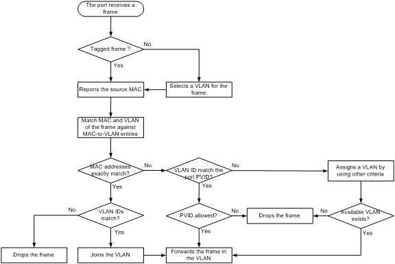
Dynamic MAC-based VLAN assignment uses the following workflow, as shown in Figure 3:
1. When a port receives a frame, it first determines whether the frame is tagged.
¡ If the frame is tagged, the port reports the source MAC address of the frame.
¡ If the frame is untagged, the port selects a VLAN for the frame by using the following matching order:
- MAC-based VLAN.
- IP subnet-based VLAN.
- Protocol-based VLAN.
- Port-based VLAN.
After tagging the frame with the selected VLAN, the port reports the source MAC address of the frame.
2. The port uses the source address and VLAN of the frame to match the MAC-to VLAN entries.
¡ If the source MAC address of the frame exactly matches the MAC address in a MAC-to-VLAN entry, the port checks whether the VLAN ID of the frame matches the VLAN in the entry.
- If the two VLAN IDs match, the port joins the VLAN and forwards the frame.
- If the two VLAN IDs do not match, the port drops the frame.
¡ If the source MAC address of the frame does not match any MAC addresses in MAC-to-VLAN entries exactly, the port checks whether the VLAN ID of the frame is its PVID.
- If the VLAN ID of the frame is the PVID of the port, the port determines whether it allows the PVID. If the PVID is allowed, the port forwards the frame within the PVID. If the PVID is not allowed, the port drops the frame.
- If the VLAN ID of the frame is not the PVID of the port, the port matches the VLAN ID of the frame by using other criteria, such as IP subnet or protocol, and forwards the frame. If no VLAN is available, the port drops the frame.
Figure 3 Flowchart for processing a frame in dynamic MAC-based VLAN assignment
When you configure dynamic MAC-based VLAN assignment, follow these guidelines:
· When a port joins a VLAN specified in the MAC-to-VLAN entry, one of the following events occurs depending on the port configuration:
¡ If the port has not been configured to allow packets from the VLAN to pass through, the port joins the VLAN as an untagged member.
¡ If the port has been configured to allow packets from the VLAN to pass through, the port configuration remains the same.
· If you configure both static and dynamic MAC-based VLAN assignments on a port, dynamic MAC-based VLAN assignment takes effect.
· When a packet matches a MAC-to-VLAN entry, the device determines a forwarding policy for the packet according to the 802.1p priority of the VLAN in the MAC-to-VLAN entry.
Server-assigned MAC-based VLAN
Use the server-assigned MAC-based VLAN feature with access authentication, such as MAC-based 802.1X authentication, to implement secure and flexible terminal access. In addition to configuring the server-assigned MAC-based VLAN feature on the device, you must configure the username-to-VLAN entries on the access authentication server.
When a user passes authentication of the access authentication server, the server issues the VLAN ID for the user to the device. The device then performs the following operations:
1. Generates a MAC-to-VLAN entry by using the source MAC address of the user packet and the received VLAN ID. The VLAN is a MAC-based VLAN.
2. Assigns the port that connects the user to the MAC-based VLAN.
When the user goes offline, the device automatically deletes the MAC-to-VLAN entry and removes the port from the MAC-based VLAN. For more information about 802.1X and MAC authentication, see Security Configuration Guide.
Configuration restrictions and guidelines
When you configure MAC-based VLANs, follow these restrictions and guideline:
· Do not configure a VLAN as both a super VLAN and a MAC-based VLAN.
· As a best practice, do not both configure dynamic MAC-based VLAN assignment and disable MAC address learning on a port. If the two features are configured together on a port, the port forwards only packets exactly matching the MAC-to-VLAN entry and drops inexactly matching packets.
· Do not use dynamic MAC-based VLAN assignment together with 802.1X or MAC authentication.
· For successful dynamic MAC-based VLAN assignment, use static VLANs when you create MAC-to-VLAN entries.
· The MAC-based VLAN feature is mainly configured on downlink ports of user access devices. Do not enable this function with link aggregation.
· H3C recommends not using dynamic MAC-based VLAN assignment together with MSTP. In MSTP mode, if a port is blocked in the MSTI of the target VLAN, the port drops the received packets instead of delivering them to the CPU. As a result, the receiving port will not be dynamically assigned to the VLAN.
· H3C recommends not using dynamic MAC-based VLAN assignment together with PVST. In PVST mode, if the target VLAN is not permitted on a port, the port is placed in blocked state. The received packets are dropped instead of being delivered to the CPU. As a result, the receiving port will not be dynamically assigned to the VLAN.
· H3C recommends not configuring both dynamic MAC-based VLAN assignment and automatic voice VLAN assignment mode on a port. If you have to configure both of them on a port, configure dynamic MAC-based VLAN assignment first. If you configure them in a reverse order, conflict will occur. When you remove one of the configurations, the operation of the other is affected.
Configuring static MAC-based VLAN assignment
|
Step |
Command |
Remarks |
|
1. Enter system view. |
system-view |
N/A |
|
2. Create a MAC-to-VLAN entry. |
mac-vlan mac-address mac-address [ mask mac-mask ] vlan vlan-id [ dot1q priority ] |
N/A |
|
3. Enter Layer 2 Ethernet interface view. |
interface interface-type interface-number |
N/A |
|
4. Configure the link type of the port as hybrid. |
port link-type hybrid |
By default, all ports are access ports. |
|
5. Configure the hybrid port to forward packets from the MAC-based VLANs. |
port hybrid vlan vlan-id-list { tagged | untagged } |
By default, a hybrid port is an untagged member of the VLAN to which the port belongs when its link type is access. |
|
6. Enable the MAC-based VLAN feature. |
mac-vlan enable |
By default, this feature is disabled. |
|
7. (Optional.) Configure VLAN matching order. |
vlan precedence { mac-vlan | ip-subnet-vlan } |
By default, the system assigns VLANs based on the MAC address preferentially. |
Configuring dynamic MAC-based VLAN assignment
|
Step |
Command |
Remarks |
|
1. Enter system view. |
system-view |
N/A |
|
2. Create a MAC-to-VLAN entry. |
mac-vlan mac-address mac-address vlan vlan-id [ dot1q priority ] |
The VLAN assignment for a port is triggered only when the source MAC address of its receiving packet exactly matches the MAC address in the MAC-to-VLAN entry. |
|
3. Enter Layer 2 Ethernet interface view. |
interface interface-type interface-number |
N/A |
|
4. Configure the link type of the port as hybrid. |
port link-type hybrid |
By default, all ports are access ports. |
|
5. Enable the MAC-based VLAN feature. |
mac-vlan enable |
By default, MAC-based VLAN is disabled. |
|
6. Enable dynamic MAC-based VLAN assignment. |
mac-vlan trigger enable |
By default, dynamic MAC-based VLAN assignment is disabled. |
|
7. (Optional.) Configure VLAN matching order. |
By default, the system assigns VLANs based on the MAC address preferentially.. When you enable dynamic MAC-based VLAN assignment, H3C recommends that you configure the vlan precedence mac-vlan command to ensure the priority of MAC-based VLAN matching. If you execute the vlan precedence ip-subnet-vlan command, the command will not take effect. |
|
|
8. (Optional.) Disable the port from forwarding packets that fail the exact MAC address match in its PVID. |
By default, when a port receives packets whose source MAC addresses fail the exact match, the port forwards them in its PVID. |
Configuring server-assigned MAC-based VLAN
|
Step |
Command |
Remarks |
|
1. Enter system view. |
system-view |
N/A |
|
2. Enter Layer 2 Ethernet interface view. |
interface interface-type interface-number |
N/A |
|
3. Configure the link type of the ports as hybrid. |
port link-type hybrid |
By default, all ports are access ports. |
|
4. Configure the hybrid port to forward packets from the MAC-based VLANs. |
By default, a hybrid port is an untagged member of the VLAN to which the port belongs when its link type is access. |
|
|
5. Enable the MAC-based VLAN feature. |
mac-vlan enable |
By default, MAC-based VLAN is disabled. |
|
6. Configure 802.1X or MAC authentication. |
For more information, see Security Command Reference. |
N/A |
Configuring IP subnet-based VLANs
In this method, packets are assigned to VLANs based on their source IP addresses and subnet masks. A port configured with IP subnet-based VLANs assigns a received untagged packet to a VLAN based on the source address of the packet.
Use this feature when packets from an IP subnet or IP address must be transmitted in a VLAN.
This feature is available only on hybrid ports, and it processes only untagged packets.
An IP subnet-based VLAN has one or multiple subnets to match inbound packets. Each subnet has a unique index in the IP subnet-based VLAN. All subnets in an IP subnet-based VLAN have the same VLAN ID.
To configure a IP subnet-based VLAN:
|
Task |
Command |
Remarks |
|
1. Enter system view. |
system-view |
N/A |
|
2. Enter VLAN view. |
vlan vlan-id |
N/A |
|
3. Associate an IP subnet or IP address with the VLAN. |
ip-subnet-vlan [ ip-subnet-index ] ip ip-address [ mask ] |
By default, a VLAN is not associated with any IP subnets or IP addresses. A multicast subnet or a multicast address cannot be associated with a VLAN. |
|
4. Return to system view. |
quit |
N/A |
|
5. Enter interface view. |
· Enter Layer 2 Ethernet interface view: · Enter Layer 2 aggregate interface view: |
· The configurations made in Layer 2 Ethernet interface view apply only to the port. · The configurations made in Layer 2 aggregate interface view apply to the aggregate interface and its aggregation member ports. If the system fails to apply the configurations to the aggregate interface, it stops applying the configurations to the aggregation member ports. If the system fails to apply the configurations to an aggregation member port, it skips the port and moves to the next member port. |
|
6. Configure the port link type as hybrid. |
port link-type hybrid |
By default, all ports are access ports. |
|
7. Assign the hybrid port to the specified IP subnet-based VLANs. |
port hybrid vlan vlan-id-list { tagged | untagged } |
By default, a hybrid port is an untagged member of the VLAN to which the port belongs when its link type is access. |
|
8. Associate the hybrid port with the specified IP subnet-based VLAN. |
port hybrid ip-subnet-vlan vlan vlan-id |
By default, no IP subnet-based VLAN is associated with a hybrid port. |
Configuring protocol-based VLANs
The protocol-based VLAN feature assigns inbound packets to different VLANs based on their protocol types and encapsulation formats. The protocols available for VLAN assignment include IP, IPX, and AT. The encapsulation formats include Ethernet II, 802.3 raw, 802.2 LLC, and 802.2 SNAP.
A protocol template defines a protocol type and an encapsulation format. A combination of a protocol-based VLAN ID and a protocol index uniquely identify a protocol template. You can assign multiple protocol templates to a protocol-based VLAN.
This feature is available only on hybrid ports, and it processes only untagged packets. It associates the available network service types with VLANs and facilitates network management and maintenance.
A protocol-based VLAN has one or multiple protocol templates. A protocol template defines a protocol type and an encapsulation format as the match criteria to match inbound packets. Each protocol template has a unique index in the protocol-based VLAN. All protocol templates in a protocol-based VLAN have the same VLAN ID.
For a port to assign inbound packets to protocol-based VLANs, perform the following tasks:
· Assign the port to the protocol-based VLANs.
· Associate the port with the protocol templates of the protocol-based VLANs.
When an untagged packet arrives at the port, the port processes the packet as follows:
· If the protocol type and encapsulation format in the packet match a protocol template, the port tags the packet with the VLAN tag specific to the protocol template.
· If no protocol templates are matched, the port tags the packet with its PVID.
To configure a protocol-based VLAN:
|
Command |
Remarks |
|
|
1. Enter system view. |
system-view |
N/A |
|
2. Enter VLAN view. |
vlan vlan-id |
If the specified VLAN does not exist, this command first creates the VLAN and enters VLAN view of this VLAN. |
|
3. Create a protocol template for the VLAN. |
protocol-vlan [ protocol-index ] { at | ipv4 | ipv6 | ipx { ethernetii | llc | raw | snap } | mode { ethernetii etype etype-id | llc { dsap dsap-id [ ssap ssap-id ] | ssap ssap-id } | snap etype etype-id } } |
By default, no protocol template is configured for a VLAN. |
|
4. Exit VLAN view. |
quit |
N/A |
|
5. Enter interface view. |
· Enter Layer 2 Ethernet interface view: · Enter Layer 2 aggregate interface view: |
· The configurations made in Layer 2 Ethernet interface view apply only to the port. · The configurations made in Layer 2 aggregate interface view apply to the aggregate interface and its aggregation member ports. If the system fails to apply the configurations to the aggregate interface, it stops applying the configurations to aggregation member ports. If the system fails to apply the configurations to an aggregation member port, it skips the port and moves to the next member port. |
|
6. Configure the port link type as hybrid. |
port link-type hybrid |
By default, all ports are access ports. |
|
7. Assign the hybrid port to the specified protocol-based VLANs. |
port hybrid vlan vlan-id-list { tagged | untagged } |
By default, a hybrid port is an untagged member of the VLAN to which the port belongs when its link type is access. |
|
8. Associate the hybrid port with the specified protocol-based VLAN. |
port hybrid protocol-vlan vlan vlan-id { protocol-index [ to protocol-end ] | all } |
By default, a port is not associated with any protocol-based VLANs. |
Configuring a VLAN group
After you configure a VLAN group on the device, the authentication sever can assign the VLAN group name to the 802.1X user that passes authentication. The VLAN group name identifies this group of VLANs. For more information about 802.1X authentication, see Security Configuration Guide.
To configure a VLAN group:
|
Step |
Command |
Remarks |
|
1. Enter system view. |
system-view |
N/A |
|
2. Create a VLAN group and enter VLAN group view. |
vlan-group group-name |
By default, no VLAN group exists. |
|
3. Add VLANs to the VLAN group. |
vlan-list vlan-id-list |
By default, no VLAN exists in a VLAN group. |
Displaying and maintaining VLANs
Execute display commands in any view.
|
Task |
Command |
|
Display VLAN interface information. |
display interface vlan-interface [ interface-number ] [ brief [ description | down ] ] |
|
Display MAC-to-VLAN entries. |
|
|
Display all ports that are enabled with the MAC-based VLAN feature. |
|
|
Display information about IP subnet-based VLANs that are associated with the specified ports. |
|
|
Display information about IP subnet-based VLANs. |
display ip-subnet-vlan vlan { vlan-id1 [ to vlan-id2 ] | all } |
|
Display information about protocol-based VLANs that are associated with the specified ports. |
|
|
Display information about protocol-based VLANs. |
display protocol-vlan vlan { vlan-id1 [ to vlan-id2 ] | all } |
|
Display VLAN information. |
display vlan [ vlan-id1 [ to vlan-id2 ] | all | dynamic | reserved | static ] |
|
Display brief VLAN information. |
|
|
Display VLAN group information. |
|
|
Display hybrid ports or trunk ports on the device. |
display port { hybrid | trunk } |
VLAN configuration examples
Port-based VLAN configuration example
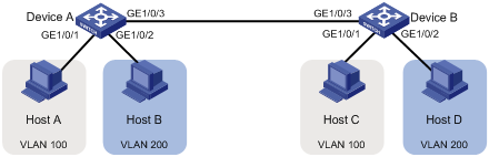
Network requirements
As shown in Figure 4:
· Host A and Host C belong to Department A. VLAN 100 is assigned to Department A.
· Host B and Host D belong to Department B. VLAN 200 is assigned to Department B.
Configure port-based VLANs so that only hosts in the same department can communicate with each other.
Configuration procedure
1. Configure Device A:
# Create VLAN 100, and assign GigabitEthernet 1/0/1 to VLAN 100.
<DeviceA> system-view
[DeviceA] vlan 100
[DeviceA-vlan100] port gigabitethernet 1/0/1
[DeviceA-vlan100] quit
# Create VLAN 200, and assign GigabitEthernet 1/0/2 to VLAN 200.
[DeviceA] vlan 200
[DeviceA-vlan200] port gigabitethernet 1/0/2
[DeviceA-vlan200] quit
# Configure GigabitEthernet 1/0/3 as a trunk port to forward packets from VLANs 100 and 200 to Device B.
[DeviceA] interface gigabitethernet 1/0/3
[DeviceA-GigabitEthernet1/0/3] port link-type trunk
[DeviceA-GigabitEthernet1/0/3] port trunk permit vlan 100 200
Please wait... Done.
2. Configure Device B in the same way Device A is configured. (Details not shown.)
3. Configure hosts:
¡ Configure Host A and Host C to be on the same IP subnet. For example, 192.168.100.0/24.
¡ Configure Host B and Host D to be on the same IP subnet. For example, 192.168.200.0/24.
Verifying the configuration
# Verify that Host A and Host C can ping each other, but they both fail to ping Host B. (Details not shown.)
# Verify that Host B and Host D can ping each other, but they both fail to ping Host A. (Details not shown.)
# Verify that VLANs 100 and 200 are correctly configured on devices, for example, on Device A.
[DeviceA-GigabitEthernet1/0/3] display vlan 100
VLAN ID: 100
VLAN type: Static
Route interface: Not configured
Description: VLAN 0100
Name: VLAN 0100
Tagged ports:
GigabitEthernet1/0/3
Untagged ports:
GigabitEthernet1/0/1
[DeviceA-GigabitEthernet1/0/3] display vlan 200
VLAN ID: 200
VLAN type: Static
Route interface: Not configured
Description: VLAN 0200
Name: VLAN 0200
Tagged ports:
GigabitEthernet1/0/3
Untagged ports:
GigabitEthernet1/0/2
MAC-based VLAN configuration example
Network requirements
As shown in Figure 5:
· GigabitEthernet 1/0/1 of Device A and Device C are each connected to a meeting room. Laptop 1 and Laptop 2 are used for meetings and might be used in either of the two meeting rooms.
· Different departments own Laptop 1 and Laptop 2. The two departments use VLANs 100 and 200, respectively.
Configure MAC-based VLANs, so that each laptop is able to access only its own department server, no matter which meeting room they are used in.
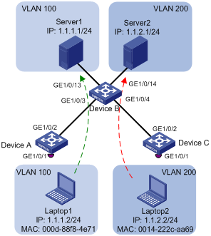
Configuration procedure
# Create VLANs 100 and 200.
[DeviceA] vlan 100
[DeviceA-vlan100] quit
[DeviceA] vlan 200
[DeviceA-vlan200] quit
# Associate the MAC addresses of Laptop 1 and Laptop 2 with VLANs 100 and 200, respectively.
[DeviceA] mac-vlan mac-address 000d-88f8-4e71 vlan 100
[DeviceA] mac-vlan mac-address 0014-222c-aa69 vlan 200
# Configure GigabitEthernet 1/0/1 as a hybrid port to forward packets from VLANs 100 and 200 without VLAN tags.
[DeviceA] interface gigabitethernet 1/0/1
[DeviceA-GigabitEthernet1/0/1] port link-type hybrid
[DeviceA-GigabitEthernet1/0/1] port hybrid vlan 100 200 untagged
# Enable the MAC-based VLAN feature on GigabitEthernet 1/0/1.
[DeviceA-GigabitEthernet1/0/1] mac-vlan enable
[DeviceA-GigabitEthernet1/0/1] quit
# Configure the uplink port GigabitEthernet 1/0/2 as a trunk port, and assign it to VLANs 100 and 200.
[DeviceA] interface gigabitethernet 1/0/2
[DeviceA-GigabitEthernet1/0/2] port link-type trunk
[DeviceA-GigabitEthernet1/0/2] port trunk permit vlan 100 200
[DeviceA-GigabitEthernet1/0/2] quit
2. Configure Device B:
# Create VLAN 100 and assign GigabitEthernet 1/0/13 to VLAN 100.
<DeviceB> system-view
[DeviceB] vlan 100
[DeviceB-vlan100] port gigabitethernet 1/0/13
[DeviceB-vlan100] quit
# Create VLAN 200 and assign GigabitEthernet 1/0/14 to VLAN 200.
[DeviceB-vlan200] port gigabitethernet 1/0/14
[DeviceB-vlan200] quit
# Configure GigabitEthernet 1/0/3 as a trunk port, and assign the port to VLANs 100 and 200.
[DeviceB] interface gigabitethernet 1/0/3
[DeviceB-GigabitEthernet1/0/3] port link-type trunk
[DeviceB-GigabitEthernet1/0/3] port trunk permit vlan 100 200
[DeviceB-GigabitEthernet1/0/3] quit
# Configure GigabitEthernet 1/0/4 as a trunk port, and assign the port to VLANs 100 and 200.
[DeviceB] interface gigabitethernet 1/0/4
[DeviceB-GigabitEthernet1/0/4] port link-type trunk
[DeviceB-GigabitEthernet1/0/4] port trunk permit vlan 100 200
[DeviceB-GigabitEthernet1/0/4] quit
3. Configure Device C in the same way as the Device A is configured. (Details not shown.)
Verifying the configuration
# Verify that Laptop 1 can access only Server 1, and Laptop 2 can access only Server 2. (Details not shown.)
# Verify the MAC-to-VLAN entries on Device A and Device C, for example, Device A.
[DeviceA] display mac-vlan all
The following MAC VLAN addresses exist:
S:Static D:Dynamic
MAC address Mask VLAN ID Dot1q State
000d-88f8-4e71 ffff-ffff-ffff 100 0 S
0014-222c-aa69 ffff-ffff-ffff 200 0 S
Total MAC VLAN address count: 2
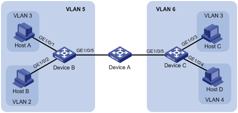
IP subnet-based VLAN configuration example
Network requirements
As shown in Figure 6, the hosts in the office belong to different IP subnets.
Configure Device C to transmit packets from 192.168.5.0/24 and 192.168.50.0/24 in VLANs 100 and 200, respectively.
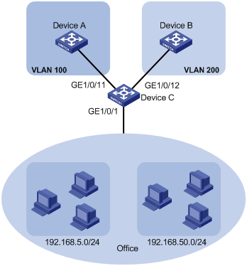
Configuration procedure
# Associate IP subnet 192.168.5.0/24 with VLAN 100.
<DeviceC> system-view
[DeviceC] vlan 100
[DeviceC-vlan100] ip-subnet-vlan ip 192.168.5.0 255.255.255.0
[DeviceC-vlan100] quit
# Associate IP subnet 192.168.50.0/24 with VLAN 200.
[DeviceC-vlan200] ip-subnet-vlan ip 192.168.50.0 255.255.255.0
[DeviceC-vlan200] quit
# Configure GigabitEthernet 1/0/11 as a hybrid port, and assign it to VLAN 100 as a tagged VLAN member.
[DeviceC] interface gigabitethernet 1/0/11
[DeviceC-GigabitEthernet1/0/11] port link-type hybrid
[DeviceC-GigabitEthernet1/0/11] port hybrid vlan 100 tagged
[DeviceC-GigabitEthernet1/0/11] quit
# Configure GigabitEthernet1/0/12 as a hybrid port, and assign it to VLAN 200 as a tagged VLAN member.
[DeviceC] interface gigabitethernet 1/0/12
[DeviceC-GigabitEthernet1/0/12] port link-type hybrid
[DeviceC-GigabitEthernet1/0/12] port hybrid vlan 200 tagged
[DeviceC-GigabitEthernet1/0/12] quit
# Configure GigabitEthernet 1/0/1 as a hybrid port, and assign it to VLANs 100 and 200 as an untagged VLAN member.
[DeviceC] interface gigabitethernet 1/0/1
[DeviceC-GigabitEthernet1/0/1] port link-type hybrid
[DeviceC-GigabitEthernet1/0/1] port hybrid vlan 100 200 untagged
# Associate GigabitEthernet 1/0/1 with IP subnet-based VLANs 100 and 200.
[DeviceC-GigabitEthernet1/0/1] port hybrid ip-subnet-vlan vlan 100
[DeviceC-GigabitEthernet1/0/1] port hybrid ip-subnet-vlan vlan 200
[DeviceC-GigabitEthernet1/0/1] quit
2. Configure Device A and Device B to forward packets from VLANs 100 and 200, respectively. (Details not shown.)
Verifying the configuration
# Display information about all IP subnet-based VLANs.
[DeviceC] display ip-subnet-vlan vlan all
VLAN ID: 100
Subnet index IP address Subnet mask
0 192.168.5.0 255.255.255.0
VLAN ID: 200
Subnet index IP address Subnet mask
0 192.168.50.0 255.255.255.0
# Display IP subnet-based VLANs on GigabitEthernet 1/0/1.
[DeviceC] display ip-subnet-vlan interface gigabitethernet 1/0/1
Interface: GigabitEthernet1/0/1
VLAN ID Subnet index IP address Subnet mask Status
100 0 192.168.5.0 255.255.255.0 Active
200 0 192.168.50.0 255.255.255.0 Active
Protocol-based VLAN configuration example
Network requirements
· The majority of hosts in a lab environment run the IPv4 protocol.
· The other hosts run the IPv6 protocol for teaching purposes.
To isolate IPv4 and IPv6 traffic at Layer 2, configure protocol-based VLANs to associate the IPv4 and ARP protocols with VLAN 100, and associate the IPv6 protocol with VLAN 200.
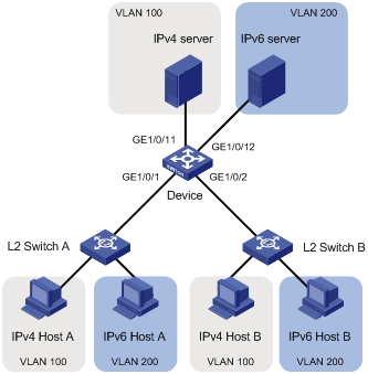
Configuration procedure
In this example, L2 Switch A and L2 Switch B use the factory configuration.
# Create VLAN 100, and configure the description for VLAN 100 as protocol VLAN for IPv4.
[Device] vlan 100
[Device-vlan100] description protocol VLAN for IPv4
# Assign GigabitEthernet 1/0/11 to VLAN 100.
[Device-vlan100] port gigabitethernet 1/0/11
[Device-vlan100] quit
# Create VLAN 200, and configure the description for VLAN 200 as protocol VLAN for IPv6.
[Device-vlan200] description protocol VLAN for IPv6
# Assign GigabitEthernet 1/0/12 to VLAN 200.
[Device-vlan200] port gigabitethernet 1/0/12
# Configure VLAN 200 as a protocol-based VLAN, and create an IPv6 protocol template with the index 1 for VLAN 200.
[Device-vlan200] protocol-vlan 1 ipv6
[Device-vlan200] quit
# Configure VLAN 100 as a protocol-based VLAN, and create an IPv4 protocol template with the index 1 for VLAN 100.
[Device] vlan 100
[Device-vlan100] protocol-vlan 1 ipv4
# Create an ARP protocol template with the index 2 for VLAN 100. (In Ethernet II encapsulation, the protocol type ID for ARP is 0x0806.)
[Device-vlan100] protocol-vlan 2 mode ethernetii etype 0806
[Device-vlan100] quit
# Configure GigabitEthernet 1/0/1 as a hybrid port, and assign it to VLANs 100 and 200 as an untagged VLAN member.
[Device] interface gigabitethernet 1/0/1
[Device-GigabitEthernet1/0/1] port link-type hybrid
[Device-GigabitEthernet1/0/1] port hybrid vlan 100 200 untagged
# Associate GigabitEthernet 1/0/1 with the IPv4 and ARP protocol templates of VLAN 100 and the IPv6 protocol template of VLAN 200.
[Device-GigabitEthernet1/0/1] port hybrid protocol-vlan vlan 100 1 to 2
[Device-GigabitEthernet1/0/1] port hybrid protocol-vlan vlan 200 1
[Device-GigabitEthernet1/0/1] quit
# Configure GigabitEthernet 1/0/2 as a hybrid port, and assign it to VLANs 100 and 200 as an untagged VLAN member.
[Device] interface gigabitethernet 1/0/2
[Device-GigabitEthernet1/0/2] port link-type hybrid
[Device-GigabitEthernet1/0/2] port hybrid vlan 100 200 untagged
# Associate GigabitEthernet 1/0/2 with the IPv4 and ARP protocol templates of VLAN 100 and the IPv6 protocol template of VLAN 200.
[Device-GigabitEthernet1/0/2] port hybrid protocol-vlan vlan 100 1 to 2
[Device-GigabitEthernet1/0/2] port hybrid protocol-vlan vlan 200 1
[Device-GigabitEthernet1/0/2] quit
2. Configure hosts and servers:
a. Configure IPv4 Host A, IPv4 Host B, and IPv4 server to be on the same network segment (192.168.100.0/24, for example). (Details not shown.)
b. Configure IPv6 Host A, IPv6 Host B, and IPv6 server to be on the same network segment (2001::1/64, for example). (Details not shown.)
Verifying the configuration
¡ The hosts and the server in VLAN 100 can successfully ping one another. (Details not shown.)
¡ The hosts and the server in VLAN 200 can successfully ping one another. (Details not shown.)
¡ The hosts or the server in VLAN 100 cannot ping the hosts or server in VLAN 200. (Details not shown.)
2. Verify the protocol-based VLAN configuration:
# Display protocol-based VLANs on Device.
[Device] display protocol-vlan vlan all
VLAN ID: 100
Protocol index Protocol type
1 IPv4
2 Ethernet II Etype 0x0806
VLAN ID: 200
Protocol index Protocol type
1 IPv6
# Display protocol-based VLANs on the ports of Device.
[Device] display protocol-vlan interface all
Interface: GigabitEthernet1/0/1
VLAN ID Protocol index Protocol type Status
100 1 IPv4 Active
100 2 Ethernet II Etype 0x0806 Active
200 1 IPv6 Active
Interface: GigabitEthernet 1/0/2
VLAN ID Protocol index Protocol type Status
100 1 IPv4 Active
100 2 Ethernet II Etype 0x0806 Active
200 1 IPv6 Active
Configuring super VLANs
Hosts in a VLAN typically use IP addresses in the same subnet. For Layer 3 interoperability with other VLANs, you can create a VLAN interface for the VLAN and assign an IP address to it. This requires a large number of IP addresses.
The super VLAN feature was introduced to save IP addresses. A super VLAN is associated with multiple sub-VLANs. These sub-VLANs use the VLAN interface of the super VLAN (also known as a super VLAN interface) as the gateway for Layer 3 communication.
You can create a VLAN interface for a super VLAN and assign an IP address to it. However, you cannot create a VLAN interface for a sub-VLAN. You can assign a physical port to a sub-VLAN, but you cannot assign a physical port to a super VLAN. Sub-VLANs are isolated at Layer 2.
You can enable Layer 3 communication between sub-VLANs by performing the following tasks:
1. Create a super VLAN and the super VLAN interface.
2. Enable local proxy ARP or ND on the super VLAN interface as follows:
¡ In an IPv4 network, enable local proxy ARP on the super VLAN interface. The super VLAN can then process ARP requests and replies sent from the sub-VLANs.
¡ In an IPv6 network, enable local proxy ND on the super VLAN interface. The super VLAN can forward and process the NS and NA messages sent from the sub-VLANs.
Super VLAN configuration task list
|
Tasks at a glance |
|
(Required.) Creating a sub-VLAN |
|
(Required.) Configuring a super VLAN |
|
(Required.) Configuring a super VLAN interface |
Creating a sub-VLAN
|
Step |
Command |
Remarks |
|
1. Enter system view. |
system-view |
N/A |
|
2. Create a sub-VLAN. |
vlan vlan-id |
By default, only the system default VLAN (VLAN 1) exists. |
Configuring a super VLAN
When you configure a super VLAN, follow these restrictions and guidelines:
· Do not configure a VLAN as both a super VLAN and a guest VLAN, Auth-Fail VLAN, or critical VLAN for a port, and vice versa. For more information about guest VLANs, Auth-Fail VLANs, and critical VLANs, see Security Configuration Guide.
· Do not configure a VLAN as both a super VLAN and a MAC-based VLAN.
· Do not configure a VLAN as both a super VLAN and a sub-VLAN.
· You can configure Layer 2 multicast for super VLANs. However, the configuration does not take effect because super VLANs do not have physical ports.
To configure a super VLAN:
|
Step |
Command |
Remarks |
|
1. Enter system view. |
system-view |
N/A |
|
2. Enter VLAN view. |
vlan vlan-id |
N/A |
|
3. Configure the VLAN as a super VLAN. |
supervlan |
By default, a VLAN is not a super VLAN. |
|
4. Associate the super VLAN with the sub-VLANs. |
subvlan vlan-id-list |
By default, a super VLAN is not associated with any sub-VLANs. Make sure the sub-VLANs already exist before associating them with a super VLAN. |
Configuring a super VLAN interface
H3C recommends not configuring VRRP for the VLAN interface of a super VLAN because the configuration affects network performance. For more information about VRRP, see High Availability Configuration Guide.
To configure a super VLAN interface:
|
Step |
Command |
Remarks |
|
1. Enter system view. |
system-view |
N/A |
|
2. Create a VLAN interface and enter its view. |
interface vlan-interface vlan-interface-id |
The vlan-interface-id argument must be the super VLAN ID. |
|
3. Configure an IP address for the VLAN interface of the super VLAN. |
· Configure an IPv4 address: · Configure an IPv6 address: |
By default, no IP address is configured for a VLAN interface. |
|
4. (Optional.) Configure Layer 3 communication between sub-VLANs. |
· Enable local proxy ARP for devices that run IPv4 protocols: · Enable local proxy ND for devices that run IPv6 protocols: |
By default: · Sub-VLANs cannot communicate with each other at Layer 3. · Local proxy ARP or ND is disabled. For more information about local proxy ARP and proxy ND, see Layer 3—IP Services Configuration Guide. For more information about local-proxy-arp enable and local-proxy-nd enable commands, see Layer 3—IP Services Command Reference. |
Displaying and maintaining super VLANs
Execute display commands in any view.
|
Task |
Command |
|
Display information about super VLANs and all sub-VLANs associated with each super VLAN. |
display supervlan [ supervlan-id ] |
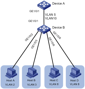
Super VLAN configuration example
Network requirements
As shown in Figure 8:
· GigabitEthernet 1/0/1 and GigabitEthernet 1/0/2 are in VLAN 2.
· GigabitEthernet 1/0/3 and GigabitEthernet 1/0/4 are in VLAN 3.
· GigabitEthernet 1/0/5 and GigabitEthernet 1/0/6 are in VLAN 5.
To save IP addresses and enable sub-VLANs to be isolated at Layer 2 but interoperable at Layer 3, perform the following tasks:
· Create a super VLAN and assign an IP address to its VLAN interface.
· Associate the super VLAN with VLANs 2, 3, and 5.
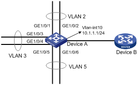
Configuration procedure
# Create VLAN 10, and configure its VLAN interface IP address as 10.1.1.1/24.
<DeviceA> system-view
[DeviceA] vlan 10
[DeviceA-vlan10] quit
[DeviceA] interface vlan-interface 10
[DeviceA-Vlan-interface10] ip address 10.1.1.1 255.255.255.0
# Enable local proxy ARP.
[DeviceA-Vlan-interface10] local-proxy-arp enable
[DeviceA-Vlan-interface10] quit
# Create VLAN 2, and assign GigabitEthernet 1/0/1 and GigabitEthernet 1/0/2 to the VLAN.
[DeviceA] vlan 2
[DeviceA-vlan2] port gigabitethernet 1/0/1 gigabitethernet 1/0/2
[DeviceA-vlan2] quit
# Create VLAN 3, and assign GigabitEthernet 1/0/3 and GigabitEthernet 1/0/4 to the VLAN.
[DeviceA] vlan 3
[DeviceA-vlan3] port gigabitethernet 1/0/3 gigabitethernet 1/0/4
[DeviceA-vlan3] quit
# Create VLAN 5, and assign GigabitEthernet 1/0/5 and GigabitEthernet 1/0/6 to the VLAN.
[DeviceA] vlan 5
[DeviceA-vlan5] port gigabitethernet 1/0/5 gigabitethernet 1/0/6
[DeviceA-vlan5] quit
# Configure VLAN 10 as a super VLAN, and associate sub-VLANs 2, 3, and 5 with the super VLAN.
[DeviceA] vlan 10
[DeviceA-vlan10] supervlan
[DeviceA-vlan10] subvlan 2 3 5
[DeviceA-vlan10] quit
[DeviceA] quit
Verifying the configuration
# Display information about super VLAN 10 and its associated sub-VLANs.
<DeviceA> display supervlan
Super VLAN ID: 10
Sub-VLAN ID: 2-3 5
VLAN ID: 10
VLAN type: Static
It is a super VLAN.
Route interface: Configured
Ipv4 address: 10.1.1.1
Ipv4 subnet mask: 255.255.255.0
Description: VLAN 0010
Name: VLAN 0010
Tagged ports: none
Untagged ports: none
VLAN ID: 2
VLAN type: Static
It is a sub VLAN.
Route interface: Configured
Ipv4 address: 10.1.1.1
Ipv4 subnet mask: 255.255.255.0
Description: VLAN 0002
Name: VLAN 0002
Tagged ports: none
Untagged ports:
GigabitEthernet1/0/1 GigabitEthernet1/0/2
VLAN ID: 3
VLAN type: Static
It is a sub VLAN.
Route interface: Configured
Ipv4 address: 10.1.1.1
Ipv4 subnet mask: 255.255.255.0
Description: VLAN 0003
Name: VLAN 0003
Tagged ports: none
Untagged ports:
GigabitEthernet1/0/3 GigabitEthernet1/0/4
VLAN ID: 5
VLAN type: Static
It is a sub VLAN.
Route interface: Configured
Ipv4 address: 10.1.1.1
Ipv4 subnet mask: 255.255.255.0
Description: VLAN 0005
Name: VLAN 0005
Tagged ports: none
Untagged ports:
GigabitEthernet1/0/5 GigabitEthernet1/0/6
Configuring the private VLAN
The private VLAN feature uses a two-tier VLAN structure, including a primary VLAN and secondary VLANs. This feature simplifies the network configuration and saves VLAN resources.
A primary VLAN is used for upstream data exchange. A primary VLAN can be associated with multiple secondary VLANs. Because the upstream device identifies only the primary VLAN and not the secondary VLANs, network configuration is simplified and VLAN resources are saved.
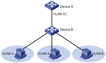
Secondary VLANs are isolated at Layer 2. To enable Layer 3 communication between secondary VLANs associated with the same primary VLAN, you can enable local proxy ARP or ND on the upstream device (for example, Device A in Figure 9).
As shown in Figure 9, the private VLAN feature is enabled on Device B. VLAN 10 is the primary VLAN. VLAN 2, VLAN 5, and VLAN 8 are secondary VLANs associated with VLAN 10 and are invisible to Device A.
Configuration task list
To configure the private VLAN feature, perform the following tasks:
1. Configure the primary VLAN.
2. Configure the secondary VLANs.
3. Configure the uplink and downlink ports:
¡ Configure the uplink port (for example, the port connecting Device B to Device A in Figure 9):
- When the port allows only one primary VLAN, configure the port as a promiscuous port of the primary VLAN. The promiscuous port can be automatically assigned to the primary VLAN and its associated secondary VLANs.
- When the port allows multiple primary VLANs, configure the port as a trunk promiscuous port of the primary VLANs. The trunk promiscuous port can be automatically assigned to these primary VLANs and their associated secondary VLANs.
¡ Configure a downlink port (for example, the port connecting Device B to a host in Figure 9) as a host port. The host port can be automatically assigned to the secondary VLAN and its associated primary VLAN.
¡ If a downlink port allows multiple secondary VLANs, configure the port as a trunk secondary port. The trunk secondary port can be automatically assigned to the secondary VLANs and their associated primary VLANs.
For more information about promiscuous, trunk promiscuous, host, and trunk secondary ports, see Layer 2—LAN Switching Command Reference.
4. Associate the secondary VLANs with the primary VLAN.
5. (Optional.) Configure Layer 3 communication between the specified secondary VLANs that are associated with the primary VLAN.
Configuration restrictions and guidelines
When you configure the private VLAN feature, follow these restrictions and guidelines:
· After you complete the private VLAN configurations, perform the following tasks:
¡ For a promiscuous port, make sure the following requirements are met:
- The primary VLAN is the PVID of the port.
- The port is an untagged member of the primary VLAN and secondary VLANs.
¡ For a host port, make sure the following requirements are met:
- The PVID of the port is a secondary VLAN.
- The port is an untagged member of the primary VLAN and the secondary VLAN.
¡ For a trunk promiscuous or trunk secondary port, make sure the port is a tagged member of the primary VLANs and the secondary VLANs.
· VLAN 1 (system default VLAN) does not support the private VLAN configuration.
Configuration procedure
To configure the private VLAN feature:
|
Step |
Command |
Remarks |
|
1. Enter system view. |
system-view |
N/A |
|
2. Create a VLAN and enter VLAN view. |
vlan vlan-id |
N/A |
|
3. Configure the VLAN as a primary VLAN. |
private-vlan primary |
By default, a VLAN is not a primary VLAN. |
|
4. Return to system view. |
quit |
N/A |
|
5. Create one or multiple secondary VLANs. |
vlan { vlan-id1 [ to vlan-id2 ] | all } |
N/A |
|
6. Enable Layer 2 communication for ports in the same secondary VLAN. |
· undo private-vlan isolated · private-vlan community |
Use either command. By default, ports in the same secondary VLAN can communicate with each other at Layer 2. This configuration takes effect when the following conditions exist: · The ports in the secondary VLAN are configured as host ports. · The secondary VLAN is associated with a primary VLAN. |
|
7. Return to system view. |
quit |
N/A |
|
8. Enter Layer 2 Ethernet interface view or Layer 2 aggregate interface view. |
interface interface-type interface-number |
N/A |
|
9. Configure the uplink port as a promiscuous or trunk promiscuous port of the specified VLANs. |
· Configure the uplink port as a promiscuous
port of the specified VLAN: · Configure the uplink port as a trunk promiscuous
port of the specified VLANs: |
By default, a port is not a promiscuous or trunk promiscuous port of any VLAN. |
|
10. Return to system view. |
quit |
N/A |
|
11. Enter Layer 2 Ethernet interface view or Layer 2 aggregate interface view. |
interface interface-type interface-number |
N/A |
|
12. Assign the downlink port to secondary VLANs. |
a. Set the link type of the port: b. Assign the access port to the specified VLAN: c. Assign the trunk port to the specified VLANs: d. Assign the hybrid port to the specified VLANs: |
Select substep b, c, or d depending on the port link type. |
|
13. Return to system view. |
quit |
N/A |
|
14. Enter Layer 2 Ethernet interface view or Layer 2 aggregate interface view. |
interface interface-type interface-number |
N/A |
|
15. Configure the downlink port as a host or trunk secondary port. |
· Configure the downlink port as a host
port: · Configure the downlink port as a trunk
secondary port: |
By default, a port is not a host or trunk secondary port. |
|
16. Enter primary VLAN view. |
vlan vlan-id |
N/A |
|
17. Associate the primary VLAN with the specified secondary VLANs. |
private-vlan secondary vlan-id-list |
By default, a primary VLAN is not associated with any secondary VLAN. |
|
18. Return to system view. |
quit |
N/A |
|
19. (Optional.) Configure Layer 3 communication between the specified secondary VLANs. |
a. Enter VLAN interface view of the primary VLAN interface: b. Enable Layer 3 communication between
secondary VLANs that are associated with the primary VLAN: c. Assign an IPv4 address
to the primary VLAN
interface: d. Assign an IPv6 address
to the primary VLAN interface: e. Enable local proxy ARP: f. Enable local proxy ND: |
Use substeps a, b, c, and e for devices that run IPv4 protocols. Use substeps a, b, d, and f for devices that run IPv6 protocols. By default: · Secondary VLANs cannot communicate with each other at Layer 3. · No IP address is configured for a VLAN interface. · Local proxy ARP and local proxy ND are disabled. |
Displaying and maintaining the private VLAN
Execute display commands in any view.
|
Task |
Command |
|
Display information about primary VLANs and the secondary VLANs associated with each primary VLAN. |
display private-vlan [ primary-vlan-id ] |
Private VLAN configuration examples
Promiscuous port configuration example
Network requirements
As shown in Figure 10, configure the private VLAN feature to meet the following requirements:
· On Device B, VLAN 5 is a primary VLAN that is associated with secondary VLANs 2 and 3. GigabitEthernet 1/0/5 is in VLAN 5. GigabitEthernet 1/0/2 is in VLAN 2. GigabitEthernet 1/0/1 is in VLAN 3.
· On Device C, VLAN 6 is a primary VLAN that is associated with secondary VLANs 3 and 4. GigabitEthernet 1/0/5 is in VLAN 6. GigabitEthernet 1/0/3 is in VLAN 3. GigabitEthernet 1/0/4 is in VLAN 4.
· Device A is aware of only VLAN 5 on Device B and VLAN 6 on Device C.
Configuration procedure
This example describes the configurations on Device B and Device C.
1. Configure Device B:
# Configure VLAN 5 as a primary VLAN.
<DeviceB> system-view
[DeviceB] vlan 5
[DeviceB-vlan5] private-vlan primary
[DeviceB-vlan5] quit
# Create VLANs 2 and 3.
[DeviceB] vlan 2 to 3
# Configure the uplink port GigabitEthernet 1/0/5 as a promiscuous port of VLAN 5.
[DeviceB] interface gigabitethernet 1/0/5
[DeviceB-GigabitEthernet1/0/5] port private-vlan 5 promiscuous
[DeviceB-GigabitEthernet1/0/5] quit
# Assign the downlink port GigabitEthernet 1/0/1 to VLAN 3, and configure the port as a host port.
[DeviceB] interface gigabitethernet 1/0/1
[DeviceB-GigabitEthernet1/0/1] port access vlan 3
[DeviceB-GigabitEthernet1/0/1] port private-vlan host
[DeviceB-GigabitEthernet1/0/1] quit
# Assign the downlink port GigabitEthernet 1/0/2 to VLAN 2, and configure the port as a host port.
[DeviceB] interface gigabitethernet 1/0/2
[DeviceB-GigabitEthernet1/0/2] port access vlan 2
[DeviceB-GigabitEthernet1/0/2] port private-vlan host
[DeviceB-GigabitEthernet1/0/2] quit
# Associate the secondary VLANs 2 and 3 with the primary VLAN 5.
[DeviceB] vlan 5
[DeviceB-vlan5] private-vlan secondary 2 to 3
[DeviceB-vlan5] quit
2. Configure Device C:
# Configure VLAN 6 as a primary VLAN.
<DeviceC> system-view
[DeviceC] vlan 6
[DeviceC–vlan6] private-vlan primary
[DeviceC–vlan6] quit
# Create VLANs 3 and 4.
[DeviceC] vlan 3 to 4
# Configure the uplink port GigabitEthernet 1/0/5 as a promiscuous port of VLAN 6.
[DeviceC] interface gigabitethernet 1/0/5
[DeviceC-GigabitEthernet1/0/5] port private-vlan 6 promiscuous
[DeviceC-GigabitEthernet1/0/5] quit
# Assign the downlink port GigabitEthernet 1/0/3 to VLAN 3, and configure the port as a host port.
[DeviceC] interface gigabitethernet 1/0/3
[DeviceC-GigabitEthernet1/0/3] port access vlan 3
[DeviceC-GigabitEthernet1/0/3] port private-vlan host
[DeviceC-GigabitEthernet1/0/3] quit
# Assign the downlink port GigabitEthernet 1/0/4 to VLAN 4, and configure the port as a host port.
[DeviceC] interface gigabitethernet 1/0/4
[DeviceC-GigabitEthernet1/0/4] port access vlan 4
[DeviceC-GigabitEthernet1/0/4] port private-vlan host
[DeviceC-GigabitEthernet1/0/4] quit
# Associate the secondary VLANs 3 and 4 with the primary VLAN 6.
[DeviceC] vlan 6
[DeviceC-vlan6] private-vlan secondary 3 to 4
[DeviceC-vlan6] quit
Verifying the configuration
# Display the private VLAN configuration on the devices, for example, on Device B.
[DeviceB] display private-vlan
Primary VLAN ID: 5
Secondary VLAN ID: 2-3
VLAN ID: 5
VLAN type: Static
Private VLAN type: Primary
Route interface: Not configured
Description: VLAN 0005
Name: VLAN 0005
Tagged ports: None
Untagged ports:
GigabitEthernet1/0/1 GigabitEthernet1/0/2 GigabitEthernet1/0/5
VLAN ID: 2
VLAN type: Static
Private VLAN type: Secondary
Route interface: Not configured
Description: VLAN 0002
Name: VLAN 0002
Tagged ports: None
Untagged ports:
GigabitEthernet1/0/2 GigabitEthernet1/0/5
VLAN ID: 3
VLAN type: Static
Private VLAN type: Secondary
Route interface: Not configured
Description: VLAN 0003
Name: VLAN 0003
Tagged Ports: None
Untagged Ports:
GigabitEthernet1/0/1 GigabitEthernet1/0/5
The output shows that:
· The promiscuous port GigabitEthernet 1/0/5 is an untagged member of primary VLAN 5 and secondary VLANs 2 and 3.
· The host port GigabitEthernet 1/0/2 is an untagged member of primary VLAN 5 and secondary VLAN 2.
· The host port GigabitEthernet 1/0/1 is an untagged member of primary VLAN 5 and secondary VLAN 3.
Trunk promiscuous port configuration example
Network requirements
As shown in Figure 11, configure the private VLAN feature to meet the following requirements:
· VLANs 5 and 10 are primary VLANs on Device B. The uplink port GigabitEthernet 1/0/1 on Device B permits the packets from VLANs 5 and 10 to pass through tagged.
· On Device B, the downlink port GigabitEthernet 1/0/2 permits secondary VLAN 2. The downlink port GigabitEthernet 1/0/3 permits secondary VLAN 3. Secondary VLANs 2 and 3 are associated with primary VLAN 5.
· On Device B, the downlink port GigabitEthernet 1/0/6 permits secondary VLAN 6. The downlink port GigabitEthernet 1/0/8 permits secondary VLAN 8. Secondary VLANs 6 and 8 are associated with primary VLAN 10.
· Device A is aware of only VLANs 5 and 10 on Device B.
Configuration procedure
1. Configure Device B:
# Configure VLANs 5 and 10 as primary VLANs.
<DeviceB> system-view
[DeviceB] vlan 5
[DeviceB-vlan5] private-vlan primary
[DeviceB-vlan5] quit
[DeviceB] vlan 10
[DeviceB-vlan10] private-vlan primary
[DeviceB-vlan10] quit
# Create VLANs 2, 3, 6, and 8.
[DeviceB] vlan 2 to 3
[DeviceB] vlan 6
[DeviceB-vlan6] quit
[DeviceB] vlan 8
[DeviceB-vlan8] quit
# Configure the uplink port GigabitEthernet 1/0/1 as a trunk promiscuous port of VLANs 5 and 10.
[DeviceB] interface gigabitethernet 1/0/1
[DeviceB-GigabitEthernet1/0/1] port private-vlan 5 10 trunk promiscuous
[DeviceB-GigabitEthernet1/0/1] quit
# Assign the downlink port GigabitEthernet 1/0/2 to VLAN 2, and configure the port as a host port.
[DeviceB] interface gigabitethernet 1/0/2
[DeviceB-GigabitEthernet1/0/2] port access vlan 2
[DeviceB-GigabitEthernet1/0/2] port private-vlan host
[DeviceB-GigabitEthernet1/0/2] quit
# Assign the downlink port GigabitEthernet 1/0/3 to VLAN 3, and configure the port as a host port.
[DeviceB] interface gigabitethernet 1/0/3
[DeviceB-GigabitEthernet1/0/3] port access vlan 3
[DeviceB-GigabitEthernet1/0/3] port private-vlan host
[DeviceB-GigabitEthernet1/0/3] quit
# Associate the secondary VLANs 2 and 3 with the primary VLAN 5.
[DeviceB] vlan 5
[DeviceB-vlan5] private-vlan secondary 2 to 3
[DeviceB-vlan5] quit
# Assign the downlink port GigabitEthernet 1/0/6 to VLAN 6, and configure the port as a host port.
[DeviceB] interface gigabitethernet 1/0/6
[DeviceB-GigabitEthernet1/0/6] port access vlan 6
[DeviceB-GigabitEthernet1/0/6] port private-vlan host
[DeviceB-GigabitEthernet1/0/6] quit
# Assign the downlink port GigabitEthernet 1/0/8 to VLAN 8, and configure the port as a host port.
[DeviceB] interface gigabitethernet 1/0/8
[DeviceB-GigabitEthernet1/0/8] port access vlan 8
[DeviceB-GigabitEthernet1/0/8] port private-vlan host
[DeviceB-GigabitEthernet1/0/8] quit
# Associate the secondary VLANs 6 and 8 with the primary VLAN 10.
[DeviceB] vlan 10
[DeviceB-vlan10] private-vlan secondary 6 8
[DeviceB-vlan10] quit
2. Configure Device A:
# Create VLANs 5 and 10.
[DeviceA] vlan 5
[DeviceA-vlan5] quit
[DeviceA] vlan 10
[DeviceA-vlan10] quit
# Configure GigabitEthernet 1/0/1 as a hybrid port, and assign it to VLANs 5 and 10 as a tagged VLAN member.
[DeviceA] interface gigabitethernet 1/0/1
[DeviceA-GigabitEthernet1/0/1] port link-type hybrid
[DeviceA-GigabitEthernet1/0/1] port hybrid vlan 5 10 tagged
[DeviceA-GigabitEthernet1/0/1] quit
Verifying the configuration
# Display primary VLAN configurations on Device B. The following output uses primary VLAN 5 as an example.
[DeviceB] display private-vlan 5
Primary VLAN ID: 5
Secondary VLAN ID: 2-3
VLAN ID: 5
VLAN type: Static
Private VLAN type: Primary
Route interface: Not configured
Description: VLAN 0005
Name: VLAN 0005
Tagged ports:
GigabitEthernet1/0/1
Untagged ports:
GigabitEthernet1/0/2 GigabitEthernet1/0/3
VLAN ID: 2
VLAN type: Static
Private VLAN type: Secondary
Route interface: Not configured
Description: VLAN 0002
Name: VLAN 0002
Tagged ports:
GigabitEthernet1/0/1
Untagged ports:
GigabitEthernet1/0/2
VLAN ID: 3
VLAN type: Static
Private VLAN type: Secondary
Route interface: Not configured
Description: VLAN 0003
Name: VLAN 0003
Tagged ports:
GigabitEthernet1/0/1
Untagged ports:
GigabitEthernet1/0/3
The output shows that:
· The trunk promiscuous port GigabitEthernet 1/0/1 is a tagged member of primary VLAN 5 and secondary VLANs 2 and 3.
· The host port GigabitEthernet 1/0/2 is an untagged member of primary VLAN 5 and secondary VLAN 2.
· The host port GigabitEthernet 1/0/3 is an untagged member of primary VLAN 5 and secondary VLAN 3.
Trunk promiscuous and trunk secondary port configuration example
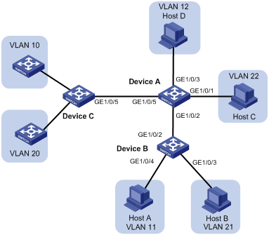
Network requirements
As shown in Figure 12, configure the private VLAN feature to meet the following requirements:
· VLANs 10 and 20 are primary VLANs on Device A. The uplink port GigabitEthernet 1/0/5 on Device A permits the packets from VLANs 10 and 20 to pass through tagged.
· VLAN 11, VLAN 12, VLAN 21, and VLAN 22 are secondary VLANs on Device A.
¡ The downlink port GigabitEthernet 1/0/2 permits the packets from VLAN 11 and VLAN 21 to pass through tagged.
¡ The downlink port GigabitEthernet 1/0/1 permits VLAN 22.
¡ The downlink port GigabitEthernet 1/0/3 permits VLAN 12.
· Secondary VLANs 11 and 12 are associated with primary VLAN 10.
· Secondary VLANs 21 and 22 are associated with primary VLAN 20.
Configuration procedure
1. Configure Device A:
# Configure VLANs 10 and 20 as primary VLANs.
<DeviceA> system-view
[DeviceA] vlan 10
[DeviceA-vlan10] private-vlan primary
[DeviceA-vlan10] quit
[DeviceA] vlan 20
[DeviceA-vlan20] private-vlan primary
[DeviceA-vlan20] quit
# Create VLANs 11, 12, 21, and 22, which are to be configured as secondary VLANs.
[DeviceA] vlan 11 to 12
[DeviceA] vlan 21 to 22
# Associate the secondary VLANs 11 and 12 with the primary VLAN 10.
[DeviceA] vlan 10
[DeviceA-vlan10] private-vlan secondary 11 12
[DeviceA-vlan10] quit
# Associate the secondary VLANs 21 and 22 with the primary VLAN 20.
[DeviceA] vlan 20
[DeviceA-vlan20] private-vlan secondary 21 22
[DeviceA-vlan20] quit
# Configure the uplink port GigabitEthernet 1/0/5 as a trunk promiscuous port of VLANs 10 and 20.
[DeviceA] interface gigabitethernet 1/0/5
[DeviceA-GigabitEthernet1/0/5] port private-vlan 10 20 trunk promiscuous
[DeviceA-GigabitEthernet1/0/5] quit
# Assign the downlink port GigabitEthernet 1/0/1 to VLAN 22 and configure the port as a host port.
[DeviceA] interface gigabitethernet 1/0/1
[DeviceA-GigabitEthernet1/0/1] port access vlan 22
[DeviceA-GigabitEthernet1/0/1] port private-vlan host
[DeviceA-GigabitEthernet1/0/1] quit
# Assign the downlink port GigabitEthernet 1/0/3 to VLAN 12 and configure the port as a host port.
[DeviceA] interface gigabitethernet 1/0/3
[DeviceA-GigabitEthernet1/0/3] port access vlan 12
[DeviceA-GigabitEthernet1/0/3] port private-vlan host
[DeviceA-GigabitEthernet1/0/3] quit
# Configure the downlink port GigabitEthernet 1/0/2 as a trunk secondary port in VLANs 11 and 21.
[DeviceA] interface gigabitethernet 1/0/2
[DeviceA-GigabitEthernet1/0/2] port private-vlan 11 21 trunk secondary
[DeviceA-GigabitEthernet1/0/2] quit
# Create VLANs 11 and 21.
<DeviceB> system-view
[DeviceB] vlan 11
[DeviceB-vlan11] quit
[DeviceB] vlan 21
[DeviceB-vlan21] quit
# Configure GigabitEthernet 1/0/2 as a hybrid port, and assign it to VLANs 11 and 21 as a tagged VLAN member.
[DeviceB] interface gigabitethernet 1/0/2
[DeviceB-GigabitEthernet1/0/2] port link-type hybrid
[DeviceB-GigabitEthernet1/0/2] port hybrid vlan 11 21 tagged
[DeviceB-GigabitEthernet1/0/2] quit
# Assign the port GigabitEthernet 1/0/4 to VLAN 11.
[DeviceB] interface gigabitethernet 1/0/4
[DeviceB-GigabitEthernet1/0/4] port access vlan 11
[DeviceB-GigabitEthernet1/0/4] quit
# Assign the port GigabitEthernet 1/0/3 to VLAN 21.
[DeviceB] interface gigabitethernet 1/0/3
[DeviceB-GigabitEthernet1/0/3] port access vlan 21
[DeviceB-GigabitEthernet1/0/3] quit
# Create VLANs 10 and 20.
<DeviceC> system-view
[DeviceC] vlan 10
[DeviceC-vlan10] quit
[DeviceC] vlan 20
[DeviceC-vlan20] quit
# Configure GigabitEthernet1/0/5 as a hybrid port, and assign it to VLANs 10 and 20 as a tagged VLAN member.
[DeviceC] interface gigabitethernet 1/0/5
[DeviceC-GigabitEthernet1/0/5] port link-type hybrid
[DeviceC-GigabitEthernet1/0/5] port hybrid vlan 10 20 tagged
[DeviceC-GigabitEthernet1/0/5] quit
Verifying the configuration
# Display the configuration of primary VLAN 10 on Device A.
[DeviceA] display private-vlan 10
Primary VLAN ID: 10
Secondary VLAN ID: 11-12
VLAN ID: 10
VLAN type: Static
Private-vlan type: Primary
Route interface: Not configured
Description: VLAN 0010
Name: VLAN 0010
Tagged ports:
GigabitEthernet1/0/2 GigabitEthernet1/0/5
Untagged ports:
GigabitEthernet1/0/3
VLAN ID: 11
VLAN type: Static
Private-vlan type: Secondary
Route interface: Not configured
Description: VLAN 0011
Name: VLAN 0011
Tagged ports:
GigabitEthernet1/0/2 GigabitEthernet1/0/5
Untagged ports: None
VLAN ID: 12
VLAN type: Static
Private-vlan type: Secondary
Route interface: Not configured
Description: VLAN 0012
Name: VLAN 0012
Tagged ports:
GigabitEthernet1/0/5
Untagged ports:
GigabitEthernet1/0/3
· The trunk promiscuous port GigabitEthernet 1/0/5 is a tagged member of primary VLAN 10 and secondary VLANs 11 and 12.
· The trunk secondary port GigabitEthernet 1/0/2 is a tagged member of primary VLAN 10 and secondary VLAN 11.
· The host port GigabitEthernet 1/0/3 is an untagged member of primary VLAN 10 and secondary VLAN 12.
# Display the configuration of primary VLAN 20 on Device A.
[DeviceA] display private-vlan 20
Primary VLAN ID: 20
Secondary VLAN ID: 21-22
VLAN ID: 20
VLAN type: Static
Private-vlan type: Primary
Route interface: Not configured
Description: VLAN 0020
Name: VLAN 0020
Tagged ports:
GigabitEthernet1/0/2 GigabitEthernet1/0/5
Untagged ports:
GigabitEthernet1/0/1
VLAN ID: 21
VLAN type: Static
Private-vlan type: Secondary
Route interface: Not configured
Description: VLAN 0021
Name: VLAN 0021
Tagged ports:
GigabitEthernet1/0/2 GigabitEthernet1/0/5
Untagged ports: None
VLAN ID: 22
VLAN type: Static
Private-vlan type: Secondary
Route interface: Not configured
Description: VLAN 0022
Name: VLAN 0022
Tagged ports:
GigabitEthernet1/0/5
Untagged ports:
GigabitEthernet1/0/1
The output shows that:
· The trunk promiscuous port GigabitEthernet 1/0/5 is a tagged member of primary VLAN 20 and secondary VLANs 21 and 22.
· The trunk secondary port GigabitEthernet 1/0/2 is a tagged member of primary VLAN 20 and secondary VLAN 21.
· The host port GigabitEthernet 1/0/1 is an untagged member of primary VLAN 20 and secondary VLAN 22.
Secondary VLAN Layer 3 communication configuration example
Network requirements
As shown in Figure 13, configure the private VLAN feature to meet the following requirements:
· Primary VLAN 10 on Device B is associated with secondary VLANs 2 and 3.
· The uplink port GigabitEthernet 1/0/1 is in VLAN 10.
· The IP address of VLAN-interface 10 is 192.168.1.1/24.
· The ports GigabitEthernet 1/0/2 and GigabitEthernet 1/0/3 are in VLAN 2 and VLAN 3, respectively.
· Secondary VLANs are isolated at Layer 2 but interoperable at Layer 3.
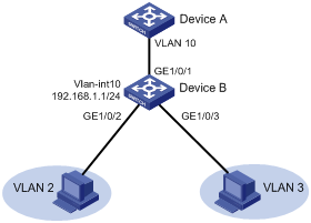
Configuration procedure
# Create VLAN 2 and VLAN 3.
<DeviceB> system-view
[DeviceB] vlan 2 to 3
[DeviceB-vlan10] private-vlan primary
[DeviceB-vlan10] private-vlan secondary 2 3
[DeviceB-vlan10] quit
# Configure the uplink port GigabitEthernet 1/0/1 as a promiscuous port of VLAN 10.
[DeviceB] interface gigabitethernet 1/0/1
[DeviceB-GigabitEthernet1/0/1] port private-vlan 10 promiscuous
[DeviceB-GigabitEthernet1/0/1] quit
# Assign the downlink port GigabitEthernet 1/0/2 to VLAN 2, and configure the port as a host port.
[DeviceB] interface gigabitethernet 1/0/2
[DeviceB-GigabitEthernet1/0/2] port access vlan 2
[DeviceB-GigabitEthernet1/0/2] port private-vlan host
[DeviceB-GigabitEthernet1/0/2] quit
# Assign the downlink port GigabitEthernet 1/0/3 to VLAN 3, and configure the port as a host port.
[DeviceB] interface gigabitethernet 1/0/3
[DeviceB-GigabitEthernet1/0/3] port access vlan 3
[DeviceB-GigabitEthernet1/0/3] port private-vlan host
[DeviceB-GigabitEthernet1/0/3] quit
[DeviceB] interface vlan-interface 10
[DeviceB-Vlan-interface10] private-vlan secondary 2 3
# Assign the IP address 192.168.1.1/24 to VLAN-interface 10.
[DeviceB-Vlan-interface10] ip address 192.168.1.1 255.255.255.0
# Enable local proxy ARP on VLAN-interface 10.
[DeviceB-Vlan-interface10] local-proxy-arp enable
[DeviceB-Vlan-interface10] quit
Verifying the configuration
# Display the configuration of primary VLAN 10.
[DeviceB] display private-vlan 10
Primary VLAN ID: 10
Secondary-VLAN ID: 2-3
VLAN ID: 10
VLAN type: Static
Private VLAN type: Primary
Route interface: Configured
IPv4 address: 192.168.1.1
IPv4 subnet mask: 255.255.255.0
Description: VLAN 0010
Name: VLAN 0010
Tagged ports: None
Untagged ports:
GigabitEthernet1/0/1
GigabitEthernet1/0/2
GigabitEthernet1/0/3
VLAN ID: 2
VLAN type: Static
Private VLAN type: Secondary
Route interface: Configured
IPv4 address: 192.168.1.1
IPv4 subnet mask: 255.255.255.0
Description: VLAN 0002
Name: VLAN 0002
Tagged ports: None
Untagged ports:
GigabitEthernet1/0/1 GigabitEthernet1/0/2
VLAN ID: 3
VLAN type: Static
Private VLAN type: Secondary
Route interface: Configured
IPv4 address: 192.168.1.1
IPv4 subnet mask: 255.255.255.0
Description: VLAN 0003
Name: VLAN 0003
Tagged ports: None
Untagged ports:
GigabitEthernet1/0/1 GigabitEthernet1/0/3
Configuring voice VLANs
Overview
A voice VLAN is used for transmitting voice traffic. When ports that connect to voice devices are assigned to a voice VLAN, the system can configure QoS parameters for voice packets to ensure higher transmission priority and sound voice quality.
Common voice devices include IP phones and integrated access devices (IADs). This chapter uses IP phone as an example.
For an IP phone to access a device, the device must perform the following operations:
· Identify the IP phone in the network and obtain the MAC address of the IP phone.
· Advertise the voice VLAN information to the IP phone.
After receiving the voice VLAN information, the IP phone can perform automatic configuration, so the voice packets sent from the IP phone can be transmitted within the voice VLAN.
Methods of identifying IP phones
Devices can use the OUI addresses or LLDP to identify IP phones.
Identifying IP phones through OUI addresses
A device determines whether a received packet is a voice packet based on its source MAC address. A packet whose source MAC address complies with any of the Organizationally Unique Identifier (OUI) addresses of the voice devices is regarded as voice traffic.
You can use system default OUI addresses (see Table 1) or configure OUI addresses for the device. You can manually remove or add the system default OUI addresses.
The switch supports 128 OUI addresses, including system default OUI addresses.
|
Number |
OUI address |
Vendor |
|
|
|
1 |
0001-E300-0000 |
Siemens phone |
||
|
2 |
0003-6B00-0000 |
Cisco phone |
||
|
3 |
0004-0D00-0000 |
Avaya phone |
||
|
4 |
00D0-1E00-0000 |
Pingtel phone |
||
|
5 |
0060-B900-0000 |
Philips/NEC phone |
||
|
6 |
00E0-7500-0000 |
Polycom phone |
||
|
7 |
00E0-BB00-0000 |
3Com phone |
||
Typically, an OUI address refers to the first 24 bits of a MAC address (in binary notation) and is a globally unique identifier that IEEE assigns to a vendor. However, OUI addresses in this chapter are addresses that the system uses to determine whether a received packet is a voice packet. They are the logical AND results of the mac-address and oui-mask arguments in the voice-vlan mac-address command.
Automatically identifying IP phones through LLDP
When you use OUI addresses to identify IP phones, the number of OUI addresses that can be configured is limited. Additionally, when there are plenty of IP phones in the network, you must configure many OUI addresses. If IP phones support LLDP, configure LLDP on the device for automatic IP phone discovery. For more information, see "Enabling LLDP for automatic IP phone discovery."
Advertising the voice VLAN information to IP phones
Figure 14 shows the workflow of advertising the voice VLAN information to IP phones.
Figure 14 Workflow of advertising the voice VLAN information to IP phones
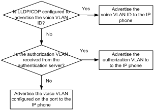
After receiving the voice VLAN information, the IP phone automatically completes the voice VLAN configuration.
· If the voice VLAN configuration is based on the received LLDP-MED TLVs or CDP packets, the IP phone will send out packets tagged with the advertised voice VLAN ID. The voice packets will be forwarded in the voice VLAN.
For more information about configuring LLDP or CDP, see "Configuring LLDP or CDP to advertise a voice VLAN." For more information about LLDP and CDP compatibility, see "Configuring LLDP."
· If the voice VLAN configuration is based on the authorization VLAN information, the IP phone will send out packets tagged with the advertised authorization VLAN ID. The voice packets will be forwarded in the authorization VLAN.
For more information about advertising the authorization VLAN information to IP phones, see "Dynamically advertising an authorization VLAN through LLDP or CDP." For more information about authorization VLANs, see Security Configuration Guide.
· If the voice VLAN configuration is based on the voice VLAN information of the accessing port, the voice traffic from the IP phone will be forwarded in the voice VLAN of the accessing port. Whether the voice packets are tagged depends on the voice VLAN configuration of the accessing port. For more information about configuring a voice VLAN on a port, see "Configuring a voice VLAN on a port."
IP phone access methods
Connecting the host and the IP phone in series
As shown in Figure 15, the host is connected to the IP phone, and the IP phone is connected to the device. In this scenario, the following requirements must be met:
· The host and the IP phone use different VLANs.
· The IP phone is able to send out VLAN-tagged packets, so that the device can differentiate traffic from the host and the IP phone.
· The port connecting to the IP phone forwards packets from the voice VLAN and the PVID.
Figure 15 Connecting the host and IP phone in series
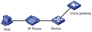
Connecting the IP phone to the device
As shown in Figure 16, the IP phone is connected to the device without the presence of the host. Use this connection method when the IP phone sends out untagged voice packets. In this scenario, you must configure the voice VLAN as the PVID of the port, and configure the port to forward the packets from the PVID.
Figure 16 Connecting the IP phone to the device
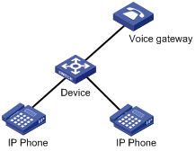
Configuring a voice VLAN on a port
Voice VLAN assignment modes
A port can be assigned to a voice VLAN automatically or manually.
Automatic mode
Use automatic mode when PCs and IP phones are connected in series to access the network through the device, as shown in Figure 15. Ports on the device transmit both voice traffic and data traffic.
When an IP phone is powered on, it sends out protocol packets. After receiving these protocol packets, the device uses the source MAC address of the protocol packets to match its OUI addresses. If the match succeeds, the system performs the following operations:
· Assigns the receiving port of the protocol packets to the voice VLAN.
· Issues ACL rules to set the packet precedence.
· Starts the voice VLAN aging timer.
The system will remove the port from the voice VLAN if no packet is received from the port before the aging timer expires. The aging timer is also configurable.
If the device reboots, the port is reassigned to the voice VLAN to ensure the correct operation of the existing voice connections. The reassignment occurs automatically without being triggered by voice traffic as long as the voice VLAN operates correctly.
Manual mode
Use manual mode when only IP phones access the network through the device, as shown in Figure 16. In this mode, ports are assigned to a voice VLAN that transmits voice traffic exclusively. No data traffic affects the voice traffic transmission.
You must manually assign the receiving port on the device to a voice VLAN. The device uses the source MAC address of the received voice packets to match its OUI addresses. If the match succeeds, the system issues ACL rules to set the packet precedence.
To remove the port from the voice VLAN, you must manually remove it.
Cooperation of voice VLAN assignment modes and IP phones
Some IP phones send out VLAN-tagged packets, and others send out only untagged packets. For correct packet processing, ports of different link types must meet specific configuration requirements in different voice VLAN assignment modes.
Table 2 Configuration requirements for access/trunk/hybrid ports to support tagged voice traffic
|
Port link type |
Voice VLAN assignment mode |
Support for tagged voice traffic |
Configuration requirements |
|
Access |
Automatic |
No |
N/A |
|
Manual |
No |
N/A |
|
|
Trunk |
Automatic |
Yes |
The PVID of the port cannot be the voice VLAN. |
|
Manual |
Yes |
The PVID of the port cannot be the voice VLAN. Configure the port to forward the packets from the voice VLAN. |
|
|
Hybrid |
Automatic |
Yes |
The PVID of the port cannot be the voice VLAN. |
|
Manual |
Yes |
The PVID of the port cannot be the voice VLAN. Configure the port to forward the packets from the voice VLAN with VLAN tags. |
Table 3 Configuration requirements for access/trunk/hybrid ports to support untagged voice traffic
|
Port link type |
Voice VLAN assignment mode |
Support for untagged voice traffic |
Configuration requirements |
|
Access |
Automatic |
No |
N/A |
|
Manual |
Yes |
Configure the voice VLAN as the PVID of the port. |
|
|
Trunk |
Automatic |
No |
N/A |
|
Manual |
Yes |
Configure the voice VLAN as the PVID of the port. Configure the port to forward the packets from the voice VLAN. |
|
|
Hybrid |
Automatic |
No |
N/A |
|
Manual |
Yes |
Configure the voice VLAN as the PVID of the port. Configure the port to forward the packets from the voice VLAN without VLAN tags. |
If an IP phone sends out tagged voice traffic, and its accessing port is configured with 802.1X authentication, guest VLAN, Auth-Fail VLAN, or critical VLAN, the VLAN ID must be different for the following VLANs:
· Voice VLAN.
· PVID of the accessing port.
· 802.1X guest, Auth-Fail, or critical VLAN.
If an IP phone sends out untagged voice traffic, the PVID of the accessing port must be the voice VLAN. As a result, 802.1X authentication is not supported.
Security mode and normal mode of voice VLANs
Depending on the incoming packet filtering mechanisms, a voice VLAN-enabled port can operate in one of the following modes:
· Normal mode—The port receives voice-VLAN-tagged packets and forwards them in the voice VLAN without examining their MAC addresses. If the PVID of the port is the voice VLAN and the port operates in manual VLAN assignment mode, the port forwards all the received untagged packets in the voice VLAN.
In this mode, voice VLANs are vulnerable to traffic attacks. Malicious users might send large quantities of forged voice-VLAN-tagged or untagged packets to consume the voice VLAN bandwidth to affect normal voice communication.
· Security mode—The port uses the source MAC addresses of voice packets to match the OUI addresses of the device. Packets that fail the match will be dropped.
In a safe network, you can configure the voice VLANs to operate in normal mode to reduce the system resource consumption in source MAC address checking.
|
|
TIP: H3C recommends not transmitting both voice traffic and non-voice traffic in a voice VLAN. If you must transmit different traffic in a voice VLAN, make sure the voice VLAN security mode is disabled. |
Table 4 Packet processing on a voice VLAN-enabled port in normal and security mode
|
Voice VLAN mode |
Packet type |
Packet processing |
|
Normal |
Untagged packets or packets with the voice VLAN tags |
The port does not examine the source MAC addresses of incoming packets. Both voice traffic and non-voice traffic can be transmitted in the voice VLAN. |
|
Packets with other VLAN tags |
Forwarded or dropped depending on whether the port allows packets from these VLANs to pass through. |
|
|
Security |
Untagged packets or packets with the voice VLAN tags |
· If the source MAC address of a packet matches an OUI address on the device, the packet is forwarded in the voice VLAN. · If the source MAC address of a packet does not match an OUI address on the device, the packet is dropped. |
|
Packets with other VLAN tags |
Forwarded or dropped depending on whether the port allows packets from these VLANs to pass through. |
Configuration prerequisites
Before you configure a voice VLAN, complete the following tasks:
· Create a VLAN.
· Determine the QoS priority settings for voice VLAN traffic.
· Determine the voice VLAN assignment mode.
Configuring the QoS priority settings for voice traffic
The QoS priority settings carried in voice traffic include the CoS and DSCP values. You can configure the device to modify the QoS priority settings for voice traffic.
Before you configure the QoS priority settings for voice traffic on a port, make sure the voice VLAN feature is disabled on it.
To configure the QoS priority settings for voice traffic:
|
Step |
Command |
Remarks |
|
1. Enter system view. |
system-view |
N/A |
|
2. Enter Layer 2 Ethernet interface view. |
interface interface-type interface-number |
N/A |
|
3. Configure QoS priority settings for incoming voice VLAN packets. |
· Configure the port to trust and retain the QoS priority settings: a. Use the 802.1p priority in incoming packets for priority mapping: b. Configure the port
to trust and retain the QoS priority
settings: · Configure the port to modify the CoS and DSCP values: |
By default, a port modifies the CoS and DSCP values for voice VLAN packets to 6 and 46, respectively. If you execute the voice-vlan qos and voice-vlan qos trust commands multiple times, the most recent configuration takes effect. For more information about the qos trust dot1p command, see ACL and QoS Command Reference. |
Configuring a port to operate in automatic voice VLAN assignment mode
Configuration restrictions and guidelines
When you configure a port to operate in automatic voice VLAN assignment mode, follow these restrictions and guidelines:
· Do not configure a VLAN as both a voice VLAN and a protocol-based VLAN. A voice VLAN in automatic mode on a hybrid port processes only tagged incoming voice traffic. A protocol-based VLAN on a hybrid port processes only untagged incoming packets. For more information about protocol-based VLANs, see "Configuring protocol-based VLANs."
· H3C recommends not using the automatic voice VLAN assignment mode together with MSTP. In MSTP mode, if a port is blocked in the MSTI of the target voice VLAN, the port drops the received packets instead of delivering them to the CPU. As a result, the receiving port will not be dynamically assigned to the voice VLAN.
· H3C recommends not using the automatic voice VLAN assignment mode together with PVST. In PVST mode, if the target voice VLAN is not permitted on a port, the port is placed in blocked state. The received packets are dropped instead of being delivered to the CPU. As a result, the receiving port will not be dynamically assigned to the voice VLAN.
· H3C recommends not configuring both dynamic MAC-based VLAN assignment and automatic voice VLAN assignment mode on a port. If you have to configure both of them on a port, configure dynamic MAC-based VLAN assignment first. If you configure them in a reverse order, conflict will occur. When you remove one of the configurations, the operation of the other is affected.
Configuration procedure
To configure a port to operate in automatic voice VLAN assignment mode:
|
Step |
Command |
Remarks |
|
1. Enter system view. |
system-view |
N/A |
|
2. (Optional.) Set the voice VLAN aging timer. |
voice-vlan aging minutes |
By default, the aging timer of a voice VLAN is 1440 minutes. The voice VLAN aging timer takes effect only on ports in automatic voice VLAN assignment mode. |
|
3. (Optional.) Enable the voice VLAN security mode. |
voice-vlan security enable |
By default, the voice VLAN security mode is enabled. |
|
4. (Optional.) Add an OUI address for voice packet identification. |
voice-vlan mac-address oui mask oui-mask [ description text ] |
By default, system default OUI addresses exist. For more information, see Table 1. |
|
5. Enter Layer 2 Ethernet interface view. |
interface interface-type interface-number |
N/A |
|
6. Configure the link type of the port. |
· port link-type trunk · port link-type hybrid |
N/A |
|
7. (Optional.) Configure the port to operate in automatic voice VLAN assignment mode. |
voice-vlan mode auto |
By default, the automatic voice VLAN assignment mode is enabled. |
|
8. Enable the voice VLAN feature on the port. |
voice-vlan vlan-id enable |
By default, the voice VLAN feature is disabled. |
Configuring a port to operate in manual voice VLAN assignment mode
Configuration restrictions and guidelines
When you configure a port to operate in manual voice VLAN assignment mode, follow these restrictions and guidelines:
· You can configure different voice VLANs on different ports on the same device. Make sure the following requirements are met:
¡ One port can be configured with only one voice VLAN.
¡ Voice VLANs must be existing static VLANs.
· Do not enable voice VLAN on the member ports of a link aggregation group. For more information about link aggregation, see "Configuring Ethernet link aggregation."
· For a port that is enabled with voice VLAN and operating in manual mode, you must manually assign the port to the voice VLAN to make the voice VLAN take effect.
Configuration procedure
To configure a port to operate in manual voice VLAN assignment mode:
|
Step |
Command |
Remarks |
|
1. Enter system view. |
system-view |
N/A |
|
2. (Optional.) Enable the voice VLAN security mode. |
voice-vlan security enable |
By default, the voice VLAN security mode is enabled. |
|
3. (Optional.) Add an OUI address for voice packet identification. |
voice-vlan mac-address oui mask oui-mask [ description text ] |
By default, system default OUI addresses exist. For more information, see Table 1. |
|
4. Enter Layer 2 Ethernet interface view. |
interface interface-type interface-number |
N/A |
|
5. Configure the port to operate in manual voice VLAN assignment mode. |
undo voice-vlan mode auto |
By default, the manual voice VLAN assignment mode is disabled. |
|
6. Assign the access, trunk, or hybrid port in manual voice VLAN assignment mode to the voice VLAN. |
· For the access port, see "Assigning an access port to a VLAN." · For the trunk port, see "Assigning a trunk port to a VLAN." · For the hybrid port, see "Assigning a hybrid port to a VLAN." |
After you assign an access port to the voice VLAN, the voice VLAN becomes the PVID of the port. |
|
7. (Optional.) Configure the voice VLAN as the PVID of the trunk or hybrid port. |
· For the trunk port, see "Assigning a trunk port to a VLAN." · For the hybrid port, see "Assigning a hybrid port to a VLAN." |
This step is required for untagged incoming voice traffic and prohibited for tagged incoming voice traffic. |
|
8. Enable the voice VLAN feature on the port. |
voice-vlan vlan-id enable |
By default, the voice VLAN feature is disabled. |
Enabling LLDP for automatic IP phone discovery
The device can automatically discover the peer through LLDP, and exchange LLDP TLVs with the peer. If the LLDP System Capabilities TLV received on a port indicates that the peer can act as a telephone, the device sends an LLDP TLV with the voice VLAN configuration to the peer.
When the IP phone discovery process is complete, the port will continue the following voice VLAN configuration:
· Join the voice VLAN.
· Increase the transmission priority of the voice traffic sent from the IP phone.
To ensure that the IP phone can pass authentication, the device will add the MAC address of the IP phone to the MAC address table.
Configuration prerequisites
Before you enable LLDP for automatic IP phone discovery, complete the following tasks:
· Enable LLDP globally and on ports.
· Complete voice VLAN configurations.
Configuration restrictions and guidelines
When you enable LLDP for automatic IP phone discovery, following these restrictions and guidelines:
· A maximum of five IP phones can be connected to each port of the device.
· Use this feature only with the automatic voice VLAN assignment mode.
· You cannot use this feature together with CDP compatibility.
Configuration procedure
To enable LLDP for automatic IP phone discovery:
|
Step |
Command |
Remarks |
|
1. Enter system view. |
system-view |
N/A |
|
2. Enable LLDP for automatic IP phone discovery. |
voice-vlan track lldp |
By default, this function is disabled. |
Configuring LLDP or CDP to advertise a voice VLAN
If IP phones support LLDP, the device advertises the voice VLAN information to the IP phones through the LLDP-MED TLVs. If IP phones support only CDP, configure CDP compatibility on the device to enable it to advertise the voice VLAN information through CDP packets.
In either case, the voice VLAN information includes the voice VLAN ID and the tagging status indicator of the voice packets. The LLDP packets sent from the device carry the priority information. The CDP packets sent from the device do not carry the priority information.
By default, if a voice VLAN is configured on the port connected to the IP phone, the device advertises this voice VLAN to the IP phone. The device learns the MAC address of the IP phone and increases the priority for voice packets. The address learning is implemented in software.
In an IRF fabric, MAC address learning and synchronization of the learned MAC address entry to all member devices in software results in an undesirable delay. In this case, you can use this feature to configure LLDP or CDP to advertise the voice VLAN ID. Then, the IRF fabric learns and synchronizes MAC address entries faster in hardware.
After you configure this feature, the device advertises the voice VLAN to the IP phone by following the workflow described in Figure 14.
To configure LLDP or CDP to advertise a voice VLAN:
|
Step |
Command |
Remarks |
|
1. Enter system view. |
system-view |
N/A |
|
2. Enter Layer 2 Ethernet interface view. |
interface interface-type interface-number |
N/A |
|
3. Configure LLDP or CDP to advertise a voice VLAN. |
· Configure LLDP to advertise a voice VLAN: · Configure CDP to advertise a voice VLAN: a. Specify the ID of an advertised VLAN: b. Configure CDP compatibility: |
By default, LLDP and CDP advertise the voice VLAN configured on the port. For more information about the lldp tlv-enable med-tlv network-policy command, see Layer 2—LAN Switching Command Reference. |
|
4. (Optional.) Display the voice VLAN advertised by LLDP. |
display lldp local-information |
The advertised voice LAN information is displayed in the MED information fields in the command output. |
Dynamically advertising an authorization VLAN through LLDP or CDP
This function is available only on IP phones that support LLDP or CDP.
Dynamic authorization VLAN advertisement through LLDP or CDP works with 802.1X or MAC authentication. If 802.1X authentication is used, make sure the IP phone support 802.1X authentication.
After the IP phone passes authentication, LLDP advertises the authorization VLAN in the LLDP-MED Network Policy TLV to the IP phone. If the IP phone supports only CDP, CDP advertises the authorization VLAN in CDP packets to the IP phone. The port connected to the IP phone will be added to the authorization VLAN.
To implement this function, perform the following configuration tasks:
1. Enable LLDP globally and on the port connected to the IP phone.
If the IP phone supports only CDP, configure CDP compatibility on the device.
2. Configure 802.1X or MAC authentication to ensure that the IP phone can pass security authentication. For more information about 802.1X and MAC authentication, see Security Configuration Guide.
3. Configure the authorization VLAN for the IP phone on the authentication server. For more information about authorization VLANs, see Security Configuration Guide.
Displaying and maintaining voice VLANs
Execute display commands in any view.
|
Task |
Command |
|
Display the voice VLAN state. |
|
|
Display the OUI addresses that the system supports. |
Voice VLAN configuration examples
Automatic voice VLAN assignment mode configuration example
Network requirements
As shown in Figure 17, Device A transmits traffic from IP phones and hosts.
For correct voice traffic transmission, perform the following tasks on Device A:
· Configure voice VLANs 2 and 3 to transmit voice packets from IP phones A and B, respectively.
· Configure GigabitEthernet 1/0/1 and GigabitEthernet 1/0/2 to operate in automatic voice VLAN assignment mode.
· Add MAC addresses of IP phones A and B to the device for voice packet identification. The mask of the two MAC addresses is FFFF-FF00-0000.
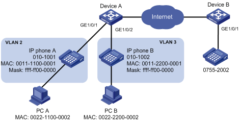
Configuration procedure
1. Configure voice VLANs:
# Create VLANs 2 and 3.
[DeviceA] vlan 2 to 3
# Set the voice VLAN aging timer to 30 minutes.
# Configure voice VLANs to operate in security mode to transmit only voice packets.
[DeviceA] voice-vlan security enable
# Add MAC addresses of IP phones A and B to the device with the mask FFFF-FF00-0000.
[DeviceA] voice-vlan mac-address 0011-1100-0001 mask ffff-ff00-0000 description IP phone A
[DeviceA] voice-vlan mac-address 0011-2200-0001 mask ffff-ff00-0000 description IP phone B
2. Configure GigabitEthernet 1/0/1:
# Configure GigabitEthernet 1/0/1 as a hybrid port.
[DeviceA] interface gigabitethernet 1/0/1
[DeviceA-GigabitEthernet1/0/1] port link-type hybrid
# Configure GigabitEthernet 1/0/1 to operate in automatic voice VLAN assignment mode.
[DeviceA-GigabitEthernet1/0/1] voice-vlan mode auto
# Enable voice VLAN on GigabitEthernet 1/0/1 and configure VLAN 2 as the voice VLAN for it.
[DeviceA-GigabitEthernet1/0/1] voice-vlan 2 enable
[DeviceA-GigabitEthernet1/0/1] quit
3. Configure GigabitEthernet 1/0/2:
# Configure GigabitEthernet 1/0/2 as a hybrid port.
[DeviceA] interface gigabitethernet 1/0/2
[DeviceA-GigabitEthernet1/0/2] port link-type hybrid
# Configure GigabitEthernet 1/0/2 to operate in automatic voice VLAN assignment mode.
[DeviceA-GigabitEthernet1/0/2] voice-vlan mode auto
# Enable voice VLAN on GigabitEthernet 1/0/2 and configure VLAN 3 as the voice VLAN for it.
[DeviceA-GigabitEthernet1/0/2] voice-vlan 3 enable
[DeviceA-GigabitEthernet1/0/2] quit
Verifying the configuration
# Display the OUI addresses and their masks and descriptions.
[DeviceA] display voice-vlan mac-address
OUI Address Mask Description
0001-e300-0000 ffff-ff00-0000 Siemens phone
0003-6b00-0000 ffff-ff00-0000 Cisco phone
0004-0d00-0000 ffff-ff00-0000 Avaya phone
000f-e200-0000 ffff-ff00-0000 H3C Aolynk phone
0060-b900-0000 ffff-ff00-0000 Philips/NEC phone
00d0-1e00-0000 ffff-ff00-0000 Pingtel phone
00e0-7500-0000 ffff-ff00-0000 Polycom phone
00e0-bb00-0000 ffff-ff00-0000 3Com phone
# Display the voice VLAN state.
[DeviceA] display voice-vlan state
Current Voice VLANs: 2
Voice VLAN security mode: Security
Voice VLAN aging time: 30 minutes
Voice VLAN enabled ports and their modes:
Port VLAN Mode COS DSCP
GigabitEthernet1/0/1 2 AUTO 6 46
GigabitEthernet1/0/2 3 AUTO 6 46
Manual voice VLAN assignment mode configuration example
Network requirements
As shown in Figure 18:
· Device A transmits only voice traffic.
· IP phone A send untagged voice traffic.
For correct voice traffic transmission, perform the following tasks on Device A:
· Configure a voice VLAN to transmit voice traffic.
· Configure GigabitEthernet 1/0/1 to operate in manual voice VLAN assignment mode.
· Add the MAC address of IP phone A to the device for voice packet identification. The mask is FFFF-FF00-0000.
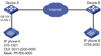
Configuration procedure
# Configure the voice VLAN to operate in security mode.
[DeviceA] voice-vlan security enable
# Add a MAC address 0011-2200-0000 with the mask FFFF-FF00-0000.
[DeviceA] voice-vlan mac-address 0011-2200-0000 mask ffff-ff00-0000 description test
# Create VLAN 2.
[DeviceA-vlan2] quit
# Configure GigabitEthernet 1/0/1 to operate in manual voice VLAN assignment mode.
[DeviceA] interface gigabitethernet 1/0/1
[DeviceA-GigabitEthernet1/0/1] undo voice-vlan mode auto
# Configure GigabitEthernet 1/0/1 as a hybrid port.
[DeviceA-GigabitEthernet1/0/1] port link-type hybrid
# Configure VLAN 2 as the PVID of GigabitEthernet 1/0/1.
[DeviceA-GigabitEthernet1/0/1] port hybrid pvid vlan 2
# Configure GigabitEthernet 1/0/1 to forward the voice traffic from VLAN 2 without VLAN tags.
[DeviceA-GigabitEthernet1/0/1] port hybrid vlan 2 untagged
# Enable voice VLAN and configure VLAN 2 as the voice VLAN on GigabitEthernet 1/0/1.
[DeviceA-GigabitEthernet1/0/1] voice-vlan 2 enable
[DeviceA-GigabitEthernet1/0/1] quit
Verifying the configuration
# Display the OUI addresses and their masks and descriptions.
[DeviceA] display voice-vlan mac-address
OUI Address Mask Description
0001-e300-0000 ffff-ff00-0000 Siemens phone
0003-6b00-0000 ffff-ff00-0000 Cisco phone
0004-0d00-0000 ffff-ff00-0000 Avaya phone
000f-e200-0000 ffff-ff00-0000 H3C Aolynk phone
0060-b900-0000 ffff-ff00-0000 Philips/NEC phone
00d0-1e00-0000 ffff-ff00-0000 Pingtel phone
00e0-7500-0000 ffff-ff00-0000 Polycom phone
00e0-bb00-0000 ffff-ff00-0000 3Com phone
# Display the voice VLAN state.
[DeviceA] display voice-vlan state
Current Voice VLANs: 1
Voice VLAN security mode: Security
Voice VLAN aging time: 1440 minutes
Voice VLAN enabled ports and their modes:
Port VLAN Mode CoS DSCP