- Table of Contents
- Related Documents
-
| Title | Size | Download |
|---|---|---|
| 01-Text | 3.09 MB |
Logging in to the Web interface
Logging in to the Web interface for the first time
Logging out of the Web interface
Displaying settings of a table entry
Feature navigator in system view
Feature navigator in network view
All networks menu in network view
Aggregation states of member ports in an aggregation group
Aging timer for dynamic MAC address entries
IP address configuration methods
EUI-64 address-based interface identifiers
IPv6 global unicast address configuration methods
IPv6 link-local address configuration methods
Dynamic domain name resolution
Periodic online user reauthentication
Mandatory authentication domain
File system management restrictions and guidelines
Bandwidth guaranteeing features
EDCA parameters and ACK policies
EDCA parameters of AC queues for clients
Configuring device classification
User-defined attack detection based on signatures
Configuring the alarm-ignored device list
Whitelist and blacklist features
Configuration restrictions and guidelines
Periodic online user reauthentication
Mandatory authentication domain
BYOD endpoint identification rules
System features configuration examples
Network settings configuration examples
Intra-AC roaming configuration example
Inter-AC roaming configuration example
Layer 2 static aggregation configuration example
Layer 2 dynamic aggregation configuration example
PPPoE client configuration example
MAC address table configuration example
Outbound dynamic NAT configuration example
Outbound static NAT configuration example
NAT Server for external-to-internal access configuration example
Static NAT 444 configuration example
Dynamic NAT 444 configuration example
IPv4 static route configuration example
IPv6 static route configuration example
Static IPv6 address configuration example
DHCP server configuration example
DHCP relay agent configuration example
DHCP snooping configuration example
IPv4 static DNS configuration example
IPv4 dynamic DNS configuration example
IPv4 DNS proxy configuration example
IPv6 static DNS configuration example
IPv6 dynamic DNS configuration example
IPv6 DNS proxy configuration example
IGMP snooping configuration example
MLD snooping configuration example
Proxy ARP configuration example
ARP attack protection configuration example
Using the device as the Stelnet server for password authentication configuration example
Network security configuration examples
ACL-based packet filter configuration example
Administrators configuration example
Network configuration examples
Wireless configuration examples
CAPWAP tunnel establishment through DHCP configuration example
CAPWAP tunnel establishment through DNS configuration example
AP group configuration example
Radio management configuration example
WIPS device classification and countermeasures configuration example
WIPS malformed packet and flood attack detection configuration example
Signature-based attack detection configuration example
Client rate limiting configuration example
Bandwidth guaranteeing configuration example
Shared key authentication configuration example
PSK authentication and bypass authentication configuration example
PSK authentication and MAC authentication configuration example
802.1X RADIUS authentication configuration example
802.1X local authentication configuration example
802.1X AKM configuration example
Direct portal authentication configuration example
WLAN RRM DFS configuration example
WLAN RRM TPC configuration example
Session-mode load balancing configuration example for radios
Traffic-mode load balancing configuration example for radios
Bandwidth-mode load balancing configuration example for radios
Session-mode load balancing configuration example for a load balancing group
Traffic-mode load balancing configuration example for a load balancing group
Bandwidth-mode load balancing configuration example for a load balancing group
Band navigation configuration example
Wireless locating configuration example
Network security configuration examples
Guest management configuration example
Local packet capture configuration example
Remote packet capture configuration example
Logging in to the Web interface
Log in to the Web interface through HTTP or HTTPS.
Restrictions and guidelines
To ensure a successful login, verify that your operating system and Web browser meet the requirements, and follow the guidelines in this section.
To log in to the Web interface when the device starts up with the factory default configuration, you must select a region code first on the region code configuration page.
Web browser requirements
As a best practice, use the following Web browsers:
· Internet Explorer 10 or higher.
· Mozilla Firefox 30.0.0.5269 or higher
· Google Chrome 35.0.1916.114 or higher.
· Safari 5.1 or higher.
To access the Web interface, you must use the following browser settings:
· Accept the first-party cookies (cookies from the site you are accessing).
· To ensure correct display of webpage contents after software upgrade or downgrade, clear data cached by the browser before you log in.
· Enable active scripting or JavaScript, depending on the Web browser.
· If you are using a Microsoft Internet Explorer browser, you must enable the following security settings:
¡ Run ActiveX controls and plug-ins.
¡ Script ActiveX controls marked safe for scripting.
Default login settings
Use settings in Table 1 for the first login.
Table 1 Default login settings
|
Item |
Setting |
|
Device IP (VLAN-interface 1) |
192.168.0.100 |
|
IP address mask |
255.255.0.0 |
|
Username |
admin |
|
Password |
admin |
|
User role |
network-admin |
Concurrent login users
The Web interface allows a maximum of 64 concurrent accesses. If this limit is reached, login attempts will fail.
Logging in to the Web interface for the first time
|
|
IMPORTANT: · For security purposes, change the login information and assign access permissions immediately after the first successful login. · To configure the device in the Web interface, you must first select a region code after you log in to the Web interface for the first time. |
By default, HTTP and HTTPS are enabled.
To log in to the Web interface:
1. Use an Ethernet cable to connect the configuration terminal to an Ethernet port on the device.
2. Log in to the device through the console port, and then execute the display interface vlan-interface 1 command.
3. Assign the login host an IP address in the same subnet as the device.
4. Open the browser, and then enter login information:
a. In the address bar, enter the IP address of the device.
- HTTP access—Enter the address in the http://ip-address:port or ip-address:port format.
- HTTPS access—Enter the address in the https://ip-address:port format.
The ip-address argument represents the IP address of the device. The port argument represents the HTTP or HTTPS service port. The default port number is 80 for HTTP and 443 for HTTPS. You do not need to enter the port number if you have not changed the service port setting.
b. On the login page, enter the default username (admin) and the default password (admin).
c. Click Login.
5. Change the login information:
¡ To change the IP address of the device, perform the following tasks:
- Click the system view tab at the bottom of the page.
- From the navigation tree, select Network Configuration > Network Services > IP Services. You are placed on the IP tab.
¡ To change the password of the login user (admin at the first login) or add new administrator accounts, perform the following tasks:
- Click the system view tab at the bottom of the page.
- From the navigation tree, select System > Administrators to access the administrator configuration page.
Logging out of the Web interface
|
|
IMPORTANT: · For security purposes, log out of the Web interface immediately after you finish your tasks. · You cannot log out by directly closing the browser. · The device does not automatically save the configuration when you log out of the Web interface. To prevent the loss of configuration when the device reboots, you must save the configuration. |
To log out of the Web interface:
1. Use one of the following methods to save the current configuration:
Method 1:
Click the admin icon ![]() in the upper right corner
of the Web interface, and click Save.
in the upper right corner
of the Web interface, and click Save.
Method 2:
a. Click the system view tab at the bottom of the page, select System > Management from the navigation tree.
b. Click the Configuration tab to access the configuration page.
c. Click Save Running Configuration.
Using the Web interface
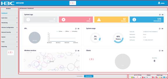
As shown in Figure 1, the Web interface contains the following areas:
|
Area |
Description |
|
(1) Banner and auxiliary area |
Contains the following items: · The H3C logo. · Device model. · Admin icon |
|
(2) Navigation tree |
Organizes feature menus in a tree in system view or in network view. |
|
(3) Content pane |
Displays information and provides an area for you to configure features. Depending on the content in this pane, the webpages include the following types: · Feature page—Contains functions or features that a feature module can provide (see "Using a feature page"). · Table page—Displays entries in a table (see "Using a table page"). · Configuration page—Contains parameters for you to configure a feature or function (see "Using a configuration page"). |
|
(4) Status area |
Displays device status and statistics. |
|
2) Navigation tree (in system view or network view) |
|
|
3) Content pane |
4) Status area |
Types of webpages
Webpages include feature, table, and configuration pages. This section provides basic information about these pages. For more information about using the icons and buttons on the pages, see "Icons and buttons."
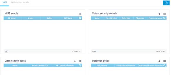
Using a feature page
As shown in Figure 2, a feature page contains information about a feature module, including its table entry statistics, features, and functions. From a feature page, you can configure features provided by a feature module.
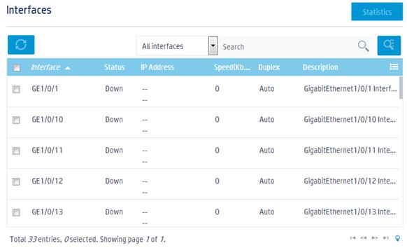
Using a table page
As shown in Figure 3, a table page displays entries in a table. To sort entries by a field in ascending or descending order, click the field. For example, click Interface to sort entries by interfaces.
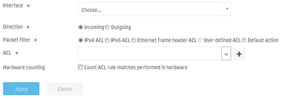
Using a configuration page
As shown in Figure 4, one configuration page contains all parameters for a configuration task. If a parameter must be configured on another page, the configuration page typically provides a link. You do not need to navigate to the destination page.
For example, you must use an ACL when you
configure a packet filter. If no ACLs are available when you perform the task,
you can click the Add icon ![]() to create an ACL. In this situation, you do
not need to navigate to the ACL management page.
to create an ACL. In this situation, you do
not need to navigate to the ACL management page.
Figure 4 Sample configuration page
Icons and buttons
Table 2 describes icons and buttons you can use to configure and manage the device.
|
Icon/button |
Icon/button name |
Task |
|
General icons |
|
|
|
|
Refresh |
Refresh statistics or information manually. |
|
|
More |
Display more contents. |
|
|
Add |
Add a new configuration entry. |
|
|
Filter |
Filter statistics or information by a specific field. |
|
Help icons |
|
|
|
|
Hint |
Obtain help information for a function or parameter. |
|
|
Note |
Display notes for a function or service. |
|
Counter icon |
|
|
|
|
Counter |
Identify the total number of table entries. |
|
Navigation icon |
|
|
|
|
Next |
Access the lower-level page to display information or configure settings. |
|
Status control icon |
|
|
|
|
Status control |
Control the enable status of the feature. · If ON is displayed, the feature is enabled. To disable the feature, click the button. · If OFF is displayed, the feature is disabled. To enable the feature, click the button. |
|
Search icons |
|
|
|
|
Search |
Enter a search expression in the search box, and then click this icon to perform a basic search. |
|
|
Advanced search |
Click this icon, and then enter a combination of criteria to perform an advanced search. |
|
Entry management icons |
|
|
|
|
Refresh |
Refresh table entries manually. |
|
|
Add |
· Add a new entry. · Confirm the addition of an entry and continue to add an additional entry. |
|
|
Export |
Export an entry. |
|
|
Delete |
Delete an entry. This icon appears at the end of an entry when you hover your mouse cursor over the entry. |
|
|
Modify |
Modify an entry. This icon appears at the end of an entry when you hover your mouse cursor over the entry. |
|
|
Bulk-delete |
Delete all entries. |
|
|
Details |
Display detailed information for an entry. This icon appears at the end of an entry when you hover your mouse cursor over the entry. |
|
|
Field selector |
Select fields to be displayed. |
|
Advanced settings icon |
|
|
|
|
Advanced settings |
Access the advanced setting page. |
|
Quick configuration icon |
|
|
|
|
Quick configuration |
Guide you through the quick configuration of a service. |
Performing basic tasks
This section describes the basic tasks that must be frequently performed when you configure or manage the device.
Saving the configuration
Typically, settings take effect immediately after you create them. However, the system does not automatically save the settings to the configuration file. They are lost when the device reboots.
To prevent settings from being lost, use one of the following methods to save the configuration:
· Click the admin icon ![]() in the upper right corner, and click Save.
in the upper right corner, and click Save.
· Perform the following tasks to access the configuration management page:
a. Click the system view tab at the bottom of the page.
b. From the navigation tree, select System > Management.
c. Click the Configuration tab.
d. Click Save Running Configuration.
Displaying settings of a table entry
1. Hover your mouse cursor over the entry.
2. Click the Detail
icon ![]() at the end of the
entry.
at the end of the
entry.
Rebooting the device
Reboot is required for some settings (for example, IRF) to take effect.
To reboot the device:
1. Save the configuration.
2. Click the system view tab at the bottom of the page.
3. From the navigation tree, select System > Management.
4. Click the Reboot tab.
5. On the reboot page, click the reboot button.
Feature navigator
Menu items and icons available to you depend on the user roles you have. By default, you can use any user roles to display information. To configure features, you must have the network-admin user role. This chapter describes all menus available for the network-admin user role.
Top-level menus differ in system view and in network view. You can toggle between these two views by clicking the view tab at the bottom of the page. For each top menu, a navigator table is provided. Use the navigator tables to navigate to the pages for the tasks you want to perform.
For example:
· To change the default device name, perform the following tasks:
a. Click the system view tab at the bottom of the page.
b. From the navigation tree, select System > Management. You are placed on the Settings tab.
· To delete an IPv4 ACL, perform the following tasks:
a. Click the system view tab at the bottom of the page.
b. From the navigation tree, select System > Resource. You are placed on the IPv4 ACL tab.
|
|
NOTE: In the navigator tables, a menu is in boldface if it has submenus. |
Feature navigator in system view
Top-level menus in system view include Dashboard, Network Configuration, Network Security, System, and Tools.
Dashboard menu
The dashboard menu provides an overview of the system and its running status, including the following information:
· Event logs.
· AP statistics.
· System utilization information.
· Wireless service statistics.
· Client statistics.
· Traffic monitoring statistics.
This menu does not contain submenus.
Network configuration menu
Use Table 3 to navigate to the tasks you can perform from the Network Configuration menu.
Table 3 Network configuration menu navigator
|
Menus |
Tasks |
|
Mobility Domain |
|
|
Roaming |
· Display WLAN client roaming information and roaming group information. · Configure WLAN client roaming settings. |
|
Network Interfaces |
|
|
Interfaces |
· Display interfaces and their attributes, including: ¡ Interface status. ¡ IP address. ¡ Speed and duplex mode. ¡ Interface description. · Delete logical interfaces. · Modify interfaces. |
|
Link Aggregation |
Create, modify, or delete Layer 2 aggregation groups. |
|
PPPoE |
Create, modify, or delete PPPoE clients. |
|
VLAN |
|
|
VLAN |
· Configure port-based VLANs. · Create VLAN-interfaces. |
|
MAC |
· Create or delete static MAC entries, dynamic MAC entries, and blackhole MAC entries. · Display existing MAC entries. |
|
STP |
· Enable or disable STP globally. · Enable or disable STP on interfaces. · Configure the STP operating mode as STP, RSTP, PVST, or MSTP. · Configure instance priorities. · Configure MST regions. |
|
Network Routing |
|
|
Routing Table |
Display IPv4 and IPv6 routing table information, including brief routing table information and route statistics. |
|
Static Routing |
· Display IPv4 and IPv6 static routing entries. · Create, modify, or delete IPv4 and IPv6 static routing entries. |
|
Network Services-IP Services |
|
|
IP |
· Configure the method to obtain an IP address (DHCP or static). · Configure the IP address or MTU of an interface. · Create a loopback interface. |
|
IPv6 |
· Configure the method to obtain an IPv6 address (manual assignment, dynamic assignment, or auto generation). · Configure the IPv6 address of an interface. · Create a loopback interface. |
|
Network Services-DHCP/DNS |
|
|
DHCP |
· Configure DHCP server functions, including: ¡ Configure DHCP services. ¡ Configure the interface to operate in the DHCP server mode. ¡ Configure DHCP address pools. ¡ Configure IP address conflict detection. · Configure DHCP relay agent functions, including: ¡ Configure DHCP services. ¡ Configure the DHCP relay agent mode. ¡ Configure the IP address of the DHCP server. · Configure settings for DHCP relay entry, include: ¡ Recording of DHCP relay entries. ¡ Periodic refreshing of DHCP relay entries. ¡ Interval for refreshing DHCP relay entries. |
|
DHCP Snooping |
· Configure a port as a trusted or untrusted port. · Record and back up DHCP snooping entries. · Configure the following features for DHCP snooping ports: ¡ MAC address check. ¡ DHCP-REQUEST check. ¡ DHCP packet rate limit. ¡ Max DHCP snooping entries. · Enable support for Option 82. If Option 82 is enabled, you can configure the handling strategy, the padding format, and the padding contents for Option 82. |
|
IPv4 DNS |
· Configure IPv4 static domain name resolution. · Configure IPv4 dynamic domain name resolution. · Configure the DNS proxy. · Configure IPv4 domain name suffixes. |
|
Dynamic DNS |
· Manage dynamic DNS policies. · Configure an interface to be associated with the dynamic DNS policy. |
|
IPv6 DNS |
· Configure static and dynamic IPv6 domain name resolution. · Configure the IPv6 DNS proxy. · Configure IPv6 domain name suffixes. |
|
Network Services-Multicast |
|
|
IGMP Snooping |
Configure IGMP snooping functions, including: · Enable or disable IGMP snooping in a VLAN. · Query IGMP snooping entries. · Enable dropping unknown multicast data. · Configure the IGMP snooping querier. · Enable fast-leave processing. · Set the maximum number of multicast groups on a port. |
|
MLD Snooping |
Configure MLD snooping functions, including: · Enable or disable MLD snooping in a VLAN. · Query MLD snooping entries. · Enable dropping unknown IPv6 multicast data. · Configure the MLD snooping querier. · Enable fast-leave processing. · Set the maximum number of IPv6 multicast groups on a port. |
|
Network Services-ARP |
|
|
ARP |
· Add static ARP entries. · Delete dynamic ARP entries and static ARP entries. · Configure the ARP proxy. · Configure gratuitous ARP. · Configure ARP attack protection. |
|
Network Services-ND |
|
|
ND |
· Add static ND entries. · Delete dynamic ND entries and static ND entries. · Configure the aging time for stale ND entries. · Enable or disable link local ND entry minimization. · Configure hop limit. · Configure RA prefix attributes, including: ¡ Address prefix. ¡ Prefix length. ¡ Valid lifetime. ¡ Preferred lifetime. · Configure RA settings for an interface, including: ¡ RA message suppression. ¡ Maximum and minimum intervals for sending RA messages. ¡ M-flag. ¡ MTU option. ¡ Hop limit. ¡ O-flag. ¡ Router lifetime. ¡ NS message retransmit interval. ¡ Router preference. ¡ Neighbor reachable time. · Enable common and local ND proxy on an interface. · Configure ND rules for the interface, including: ¡ Maximum number of dynamic neighbor entries. ¡ Maximum number of DAD attempts. |
|
Network Services-NAT |
|
|
NAT |
· Configure dynamic and static NAT, internal servers, and dynamic and static NAT444. · Configure NAT address groups, NAT444 address groups, port block groups, and server groups. · Configure PAT mode, DNS mappings, and NAT hairpin. · Enable NAT ALG. · Display NAT logs. |
|
Network Services-Management Protocols |
|
|
HTTP/HTTPS |
· Enable or disable HTTP service. · Enable or disable HTTPS service. · Set the Web connection timeout. · Set the HTTP service port number. · Set the HTTPS service port number. · Specify Web access control ACLs. |
|
FTP |
· Enable or disable FTP service. · Set the DSCP value for the device to use for outgoing FTP packets. · Specify FTP access control ACLs. · Set the FTP connection idle timeout. · Configure SSL service policies. |
|
Telnet |
· Enable or disable Telnet service. · Set the DSCP values for the device to use for outgoing IPv4 or IPv6 Telnet packets. · Specify Telnet access control ACLs. |
|
SSH |
· Enable or disable the Stelnet, SFTP, and SCP services. · Configure SSH parameters. |
|
NTP |
· Enable or disable the NTP service. · Configure the IP address and stratum level of the local clock. · Set an NTP authentication key. |
|
LLDP |
· Enable or disable LLDP. · Enable or disable CDP compatibility. · Configure LLDP parameters. · Display interface status. · Configure the interface status. · Display LLDP neighbors. · Configure LLDP to advertise the specified TLVs. |
|
Settings |
· Enable or disable log output to the log buffer, and configure the maximum number of logs in the log buffer. · Configure the address and port number of log hosts. |
Network security menu
Use Table 4 to navigate to the tasks you can perform from the Network Security menu.
Table 4 Network security menu navigator
|
Menus |
Tasks |
|
Packet Filter |
|
|
Packet Filter |
· Create, modify, or delete a packet filter for an interface, a VLAN, or the system. · Configure the default action for the packet filter. |
|
Traffic Policy |
|
|
QoS Policies |
· Create, modify, or delete interface QoS policies. · Create, modify, or delete VLAN QoS policies. · Create, modify, or delete global QoS policies. |
|
Priority Mapping |
· Query or configure the port priority. · Configure the priority trust mode for a port. · Query or modify the 802.1p-to-local priority mapping table. · Query or modify the DSCP-to-802.1p priority mapping table. · Query or modify the DSCP-to-DSCP priority mapping table. |
|
Access Control |
|
|
802.1X |
· Enable or disable 802.1X. · Configure the 802.1X authentication method. · Configure the port access control method. · Configure the maximum number of concurrent 802.1X users on the port. · Configure advanced 802.1X features. |
|
Authentication |
|
|
ISP Domains |
Configure ISP domains. |
|
RADIUS |
Configure RADIUS schemes. |
|
User Management |
|
|
Local Users |
· Add, modify, delete, import, or export local users. · Add, modify, or delete local user groups. |
System menu
Use Table 5 to navigate to the tasks you can perform from the System menu.
|
Menus |
Tasks |
|
Event Logs |
|
|
Event Logs |
Query, collect, or delete log information. |
|
Resource |
|
|
IPv4 ACL |
· Create, modify, or delete an IPv4 basic ACL. · Create, modify, or delete an IPv4 advanced ACL. |
|
IPv6 ACL |
· Create, modify, or delete an IPv6 basic ACL. · Create, modify, or delete an IPv6 advanced ACL. |
|
Layer 2 ACLs |
Create, modify, or delete an Ethernet frame header ACL. |
|
Time range |
Create, modify, or delete a time range. |
|
File Systems |
|
|
File System Management |
Upload, download, or delete files. |
|
Administrators |
|
|
Administrators |
· Create, modify, or delete roles. · Create, modify, or delete administrators. · Configure the role of administrators. · Control administrator access authority. · Manage passwords. |
|
Management |
|
|
Settings |
· Set the name, location, and contact information of the device. · Set the system time. |
|
Configuration |
· Save or export the running configuration. · Import configuration. · Display the running configuration. · Restore the settings to the factory defaults. |
|
Upgrade |
· Upgrade system software. · Display system software lists, including: ¡ List of software enabled at the current system startup. ¡ List of main software to be enabled at the next system startup. |
|
Reboot |
Reboot the device. |
|
About |
Display basic device information, including device name, serial number, model, description, location, contact information, version, electronic label, and statement. |
Tools menu
Use Table 6 to navigate to the tasks you can perform from the Tools menu.
|
Menus |
Tasks |
|
Debug |
|
|
Diagnostics |
Collect diagnostic information for locating problems. |
Feature navigator in network view
Top-level menus in network view include Dashboard, Quick Start, Monitoring, Wireless Configuration, Network Security, System , Tools, and Reporting.
Dashboard menu
The dashboard menu provides an overview of the system and its running status, including the following information:
· Event logs.
· AP statistics.
· System utilization information.
· Wireless service statistics.
· Client statistics.
· Traffic monitoring statistics.
This menu does not contain submenus.
Quick start menu
Use Table 7 to navigate to the tasks you can perform from the Quick Start menu.
Table 7 Quick start menu navigator
|
Menus |
Tasks |
|
Add New AP |
|
|
Add New AP |
Add new APs manually. |
|
Add New SSID |
|
|
Add New SSID |
· Configure wireless services. · Configure link layer authentication. · Enable or disable authorization. · Enable or disable intrusion detection. · Configure key management. · Bind APs. |
|
Add New User |
|
|
Add New User |
Add new users. |
Monitoring menu
Use Table 8 to navigate to the tasks you can perform from the Monitoring menu.
Table 8 Monitoring menu navigator
|
Menus |
Tasks |
|
Wireless Networks |
|
|
Wireless Services |
Display wireless services. |
|
Access Points |
|
|
APs |
Display AP statistics. |
|
AP Groups |
Display AP groups. |
|
Clients |
|
|
Clients |
Display client statistics. |
|
Wireless Security |
|
|
WIPS |
Display WIPS statistics. |
|
RRM |
|
|
RF Optimization |
Display channel and power adjustment information. |
|
Spectrum Analysis |
Display detailed information about spectrum analysis. |
|
Client Proximity Sensor |
|
|
Client Proximity Sensor |
Display client proximity sensor information. |
Wireless configuration menu
Use Table 9 to navigate to the tasks you can perform from the Wireless Configuration menu.
Table 9 Wireless configuration menu navigator
|
Menus |
Tasks |
|
Wireless Networks |
|
|
Wireless Networks |
· Display wireless services. · Add, delete, or modify wireless services. · Configure link layer authentication. · Enable or disable authorization and intrusion detection. · Manage keys. · Bind APs. |
|
AP Management |
|
|
AP |
Add, modify, delete, or query APs. |
|
AP Groups |
Create, query, modify, or delete AP groups. |
|
AP Global Settings |
· Configure AP region codes. · Enable or disable region code lock. · Enable or disable AP software upgrade. · Enable or disable auto AP. · Enable or disable auto-AP persistence. |
|
AP Provisioning |
Display or modify AP preprovisioned settings. |
|
AP Group Provisioning |
Display or modify AP group preprovisioned settings. |
|
Wireless QoS |
|
|
Client Rate Limiting |
· Display detailed information about client rate limit. · Configure client-type-based client rate limit. · Configure service-based client rate limit. · Configure AP radio or AP group radio-based client rate limit. |
|
Bandwidth Guaranteeing |
· Display detailed information about intelligent bandwidth guarantee. · Set the maximum radio bandwidth. · Configure intelligent bandwidth guarantee for an AP or AP group. |
|
Wi-Fi Multimedia |
· Display wireless QoS status and information. · Display radio EDCA parameters. · Display radio and client negotiation parameters. · Display WMM statistics for clients. · Display transport stream information. |
|
Wireless Security |
|
|
WIPS |
· Display detailed WIPS information. · Enable WIPS. · Configure VSDs. · Configure classification policies. · Configure attack detection policies. · Configure signature policies. · Configure countermeasure policies. · Configure AP classification rules. · Configure signatures. · Add MAC addresses to the alarm-ignored device list. |
|
Whitelist and blacklist |
· Configure whitelists. · Configure static and dynamic blacklists. |
|
Radio Management |
|
|
Radio Configuration |
Display detailed model and radio information for all APs in an AP group. |
|
RRM |
· Display channel and power adjustment information. · One-key channel and power optimization. · Configure RRM for APs and AP groups: ¡ Configure RRM holddown groups. ¡ Configure radio baselines. · Display RRM adjustment history. |
|
Load Balancing |
· Enable load balancing. · Configure the load balancing mode. · Configure load balancing groups. · Configure load balancing parameters. |
|
Band Navigation |
· Enable or disable global band navigation. · Enable or disable band navigation for APs and AP groups. · Configure band navigation parameters. |
|
Client Proximity Sensor |
|
|
Client Proximity Sensor |
· Enable or disable client proximity sensor. · Display client proximity sensor information. |
|
Applications |
|
|
Location Aware |
· Configure global packet rate limit, packet filtering, and packet dilution. · Configure Aeroscout locating, bluetooth locating, CUPID locating, fingerprinting, and Internet of Things (IoT) locating. |
Network security menu
Use Table 10 to navigate to the tasks you can perform from the Network Security menu.
Table 10 Network security menu navigator
|
Menus |
Tasks |
|
Packet Filter |
|
|
Packet Filter |
· Create, modify, or delete a packet filter for an interface or a VLAN, or the system. · Configure the default action for the packet filter. |
|
Traffic Policy |
|
|
QoS Policies |
· Create, modify, or delete interface QoS policies. · Create, modify, or delete VLAN QoS policies. · Create, modify, or delete global QoS policies. |
|
Priority Mapping |
· Query and configure the port priority. · Configure the priority trust mode for a port. · Query and modify the 802.1p-to-local priority mapping table. · Query and modify the DSCP-to-802.1p priority mapping table. · Query and modify the DSCP-to-DSCP priority mapping table. |
|
Access Control |
|
|
802.1X |
· Enable or disable 802.1X. · Configure the 802.1X authentication method. · Configure the port access control method. · Configure the maximum number of concurrent 802.1X users on the port. · Configure advanced 802.1X features. |
|
Authentication |
|
|
ISP Domains |
Configure ISP domains. |
|
RADIUS |
Configure RADIUS schemes. |
|
BYOD |
|
|
BYOD DB |
· Display DHCP rules, HTTP rules, and MAC rules. · Configure DHCP rules, HTTP rules, and MAC rules. |
|
BYOD Authorization |
Query or modify BYOD authorization. |
|
User Management |
|
|
Local Users |
· Add, modify, delete, import, or export local users. · Add or modify local user groups. |
|
Guest Management |
|
|
Guest List |
Query, add, or export guests. |
|
Import Guests |
Import guests. |
|
Generate Guest Accounts |
Generate guests in bulk. |
|
Approve Guest |
Approve guests. |
|
Guest Configuration |
Configure guest parameters. |
|
Access Control |
|
|
Port Security |
Configure port security features. |
|
Portal |
Configure portal authentication. |
System menu
Use Table 11 to navigate to the tasks you can perform from the System menu.
Table 11 System menu navigator
|
Menus |
Tasks |
|
Resource |
|
|
IPv4 ACL |
· Create basic or advanced IPv4 ACLs. · Modify or delete ACLs on this page and other service module pages, such as the packet filtering page. |
|
IPv6 ACL |
· Create basic or advanced IPv6 ACLs. · Modify or delete ACLs on this page and other service module pages, such as the packet filtering page. |
|
Layer 2 ACLs |
· Create Ethernet ACLs. · Modify or delete ACLs on this page and other service module pages, such as the packet filtering page. |
|
Time range |
Create, modify, or delete time ranges. |
Tools menu
Use Table 12 to navigate to the tasks you can perform from the Tools menu.
|
Menus |
Tasks |
|
Wireless Capture |
|
|
Wireless Capture |
Display captured wireless packets. |
|
Debug |
|
|
Diagnostics |
Collect diagnostic information for locating problems. |
Reporting menu
Use Table 13 to navigate to the tasks you can perform from the Reporting menu.
Table 13 Reporting menu navigator
|
Menus |
Tasks |
|
Client Statistics |
|
|
AC Frame |
Display transmitted/received/dropped AC frames. |
|
AC Bytes |
Display transmitted/received/dropped AC bytes. |
|
Total Frame |
Display total transmitted, received, and dropped frames. |
|
Total Bytes |
Display total transmitted, received, and dropped bytes. |
|
AP Statistics |
|
|
AP Statistics |
Display AP statistics. |
|
Wireless Service Statistics |
|
|
Wireless Service Statistics |
Display wireless service statistics. |
All networks menu in network view
The all networks menu displays AP group and AP information for the current AC. It associates with the AP tabs on the AP management page. To configure and manage an AP, you can click the name of an AP in the all networks menu to access the AP configuration page. For more information about the AP tabs, see Table 9.
Network services features
WLAN roaming
Overview
WLAN roaming enables clients to seamlessly roam among APs in an ESS while retaining their IP address and authorization information during the roaming process.
H3C ACs also support fast roaming, which enables RSN + 802.1X clients to roam to a new AP without being authenticated again.
Terminology
· Inter Access Controller Tunneling Protocol—IACTP is an H3C-proprietary protocol that provides a generic packet encapsulation and transport mechanism for ACs to securely communicate with each other. ACs providing roaming services establish an IACTP tunnel with each other to exchange control messages and client information.
· Home agent—A home agent is an AC that manages the AP with which a wireless client associates for the first time. If the AC that authenticates a client is not the AC with which the client associates for the first time, the AC that authenticates the client is the HA.
· Foreign agent—A foreign agent is an AC that is other than the HA and with which a client currently associates.
WLAN roaming mechanism
Clients can roam between APs managed by ACs in the same mobility group.
Intra-AC roaming
Intra-AC roaming enables clients to roam among APs that are managed by the same AC.
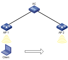
As shown in Figure 5, intra-AC roaming uses the following procedure:
1. The client comes online from AP 1, and the AC creates a roaming entry for the client.
2. The client roams to AP 2. The AC examines the roaming entry for the client and determines whether to perform fast roaming.
If the client is an RSN + 802.1X client, fast roaming is used, and the client can be associated with AP 2 without reauthentication. If it is not, the client needs to be reauthenticated before being associated with AP 2.
Inter-AC roaming
Inter-AC roaming enables clients to roam among APs that are managed by different ACs. These ACs must be in the same mobility group and have established an IACTP tunnel with each other.
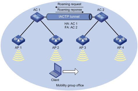
As shown in Figure 6, inter-AC roaming uses the following procedure:
1. The client comes online from AP 2. AC 1 creates a roaming entry for the client and sends the information to AC 2 through the IACTP tunnel.
2. The client roams to AP 3. AC 2 examines the roaming entry for the client and determines whether to perform fast roaming.
If the client is an RSN + 802.1X client, fast roaming is used, and the client can be associated with AP 3 without reauthentication. If it is not, the client needs to be reauthenticated before being associated with AP 3.
3. The client associates with AP 3. AC 2 sends a roaming request to AC 1.
4. AC 1 verifies the roaming request and performs either of the following operations:
¡ Sends a roaming response that indicates roaming failure to AC 2 if the request is invalid. AC 2 logs off the client.
¡ Saves the roaming trace and roam-out information and sends a roaming response that indicates roaming success to AC 2 if the request is valid. AC 2 saves roaming-in information for the client.
Link aggregation
Ethernet link aggregation bundles multiple physical Ethernet links into one logical link, called an aggregate link. Link aggregation has the following benefits:
· Increased bandwidth beyond the limits of any single link. In an aggregate link, traffic is distributed across the member ports.
· Improved link reliability. The member ports dynamically back up one another. When a member port fails, its traffic is automatically switched to other member ports.
Aggregation group
Link bundling is implemented through interface bundling. An aggregation group is a group of Ethernet interfaces bundled together. These Ethernet interfaces are called member ports of the aggregation group. Each aggregation group has a corresponding logical interface (called an aggregate interface).
When you create an aggregate interface, the device automatically creates an aggregation group of the same type and number as the aggregate interface. For example, when you create Layer 2 aggregate interface 1, Layer 2 aggregation group 1 is created.
You can assign Layer 2 Ethernet interfaces only to a Layer 2 aggregation group.
The port rate of an aggregate interface equals the total rate of its Selected member ports. Its duplex mode is the same as that of the Selected member ports.
Aggregation states of member ports in an aggregation group
A member port in an aggregation group can be in any of the following aggregation states:
· Selected—A Selected port can forward traffic.
· Unselected—An Unselected port cannot forward traffic.
Operational key
When aggregating ports, the system automatically assigns each port an operational key based on port information, such as port rate and duplex mode. Any change to this information triggers a recalculation of the operational key.
In an aggregation group, all Selected ports have the same operational key.
Attribute settings
To become a Selected port, a member port must have the same attribute settings as the aggregate interface.
|
Feature |
Considerations |
|
VLAN |
VLAN attribute settings include: · Permitted VLAN IDs. · PVID. · VLAN tagging mode. |
Link aggregation modes
An aggregation group operates in one of the following modes:
· Static—Static aggregation is stable. An aggregation group in static mode is called a static aggregation group. The aggregation states of the member ports in a static aggregation group are not affected by the peer ports.
· Dynamic—An aggregation group in dynamic mode is called a dynamic aggregation group. The local system and the peer system automatically maintain the aggregation states of the member ports, which reduces the administrators' workload.
An aggregation group in either mode must choose a reference port and then set the aggregation state of its member ports.
Aggregating links in static mode
When setting the aggregation states of the ports in an aggregation group, the system automatically picks a member port as the reference port. A Selected port must have the same operational key and attribute settings as the reference port.
The system chooses a reference port from the member ports that are in up state and have the same attribute settings as the aggregate interface.
The candidate ports are sorted in the following order:
1. Highest port priority
2. Full duplex/high speed
3. Full duplex/low speed
4. Half duplex/high speed
5. Half duplex/low speed
The candidate port at the top is chosen as the reference port.
· If multiple ports have the same port priority, duplex mode, and speed, the port that has been a Selected port (if any) is chosen. If multiple ports have been Selected ports, the one with the smallest port number is chosen.
· If multiple ports have the same port priority, duplex mode, and speed and none of them has been a Selected port, the port with the smallest port number is chosen.
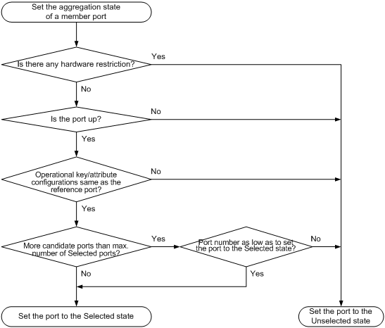
After the reference port is chosen, the system sets the aggregation state of each member port in the static aggregation group.
Figure 7 Setting the aggregation state of a member port in a static aggregation group
Aggregating links in dynamic mode
Dynamic aggregation is implemented through IEEE 802.3ad Link Aggregation Control Protocol (LACP).
LACP uses LACPDUs to exchange aggregation information between LACP-enabled devices.
Each member port in an LACP-enabled aggregation group exchanges information with its peer. When a member port receives an LACPDU, it compares the received information with information received on the other member ports. In this way, the two systems reach an agreement on which ports are placed in the Selected state.
The system chooses a reference port from the member ports that are in up state and have the same attribute settings as the aggregate interface. A Selected port must have the same operational key and attribute settings as the reference port.
The local system (the actor) and the peer system (the partner) negotiate a reference port by using the following workflow:
1. The two systems compare their system IDs to determine the system with the smaller system ID.
A system ID contains the system LACP priority and the system MAC address.
a. The two systems compare their LACP priority values.
The lower the LACP priority, the smaller the system ID. If LACP priority values are the same, the two systems proceed to the next step.
b. The two systems compare their MAC addresses.
The lower the MAC address, the smaller the system ID.
2. The system with the smaller system ID chooses the port with the smallest port ID as the reference port.
A port ID contains a port priority and a port number. The lower the port priority, the smaller the port ID.
a. The system chooses the port with the lowest priority value as the reference port.
If ports have the same priority, the system proceeds to the next step.
b. The system compares their port numbers.
The smaller the port number, the smaller the port ID.
The port with the smallest port number and the same attribute settings as the aggregate interface is chosen as the reference port.
After the reference port is chosen, the system with the smaller system ID sets the state of each member port on its side.
Figure 8 Setting the state of a member port in a dynamic aggregation group
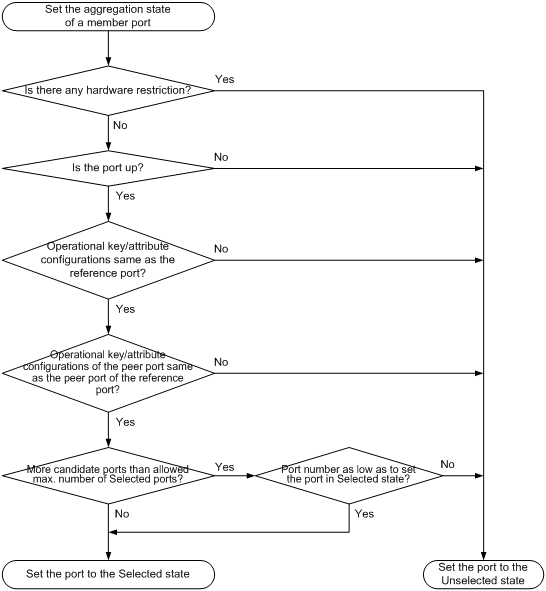
Meanwhile, the system with the higher system ID is aware of the aggregation state changes on the peer system. The system sets the aggregation state of local member ports the same as their peer ports.
PPPoE
Overview
Point-to-Point Protocol over Ethernet (PPPoE) extends PPP by transporting PPP frames encapsulated in Ethernet over point-to-point links.
PPPoE specifies the methods for establishing PPPoE sessions and encapsulating PPP frames over Ethernet. PPPoE requires a point-to-point relationship between peers instead of a point-to-multipoint relationship as in multi-access environments such as Ethernet. PPPoE provides Internet access for the hosts in an Ethernet through a remote access device and implement access control, authentication, and accounting on a per-host basis. Integrating the low cost of Ethernet and scalability and management functions of PPP, PPPoE gained popularity in various application environments, such as residential access networks.
For more information about PPPoE, see RFC 2516.
PPPoE network structure
On the Web interface, the device can act as a PPPoE client.
The following matrix shows the feature and hardware compatibility:
|
Hardware series |
Model |
PPPoE client compatibility |
|
WX1800H series |
WX1804H WX1810H WX1820H WX1840H |
Yes |
|
WX3800H series |
WX3820H WX3840H |
No |
|
WX5800H series |
WX5860H |
No |
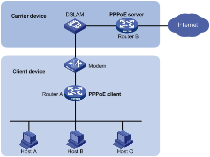
PPPoE uses the client/server model. The PPPoE client initiates a connection request to the PPPoE server. After session negotiation between them is complete, a session is established between them, and the PPPoE server provides access control, authentication, and accounting to the PPPoE client.
As shown in Figure 9, the PPPoE session is established between routers (Router A and Router B). All hosts share one PPPoE session for data transmission without being installed with PPPoE client software. This network structure is typically used by enterprises.
VLAN
The Virtual Local Area Network (VLAN) technology breaks a LAN down into multiple logical LANs, which is called VLANs. Each VLAN is a broadcast domain. Hosts in the same VLAN can directly communicate with one another. Hosts in different VLANs are isolated from one another at Layer 2.
Port-based VLANs
Port-based VLANs group VLAN members by port. A port forwards packets from a VLAN only after it is assigned to the VLAN.
You can configure a port as an untagged or tagged port of a VLAN.
· To configure the port as an untagged port of a VLAN, assign it to the untagged port list of the VLAN. The untagged port of a VLAN forwards packets from the VLAN without VLAN tags.
· To configure the port as a tagged port of a VLAN, assign it to the tagged port list of the VLAN. The tagged port of a VLAN forwards packets from the VLAN with VLAN tags.
You can configure the link type of a port as access, trunk, or hybrid. Ports of different link types use different VLAN tag handling methods.
· Access—An access port can forward packets from only one VLAN and send them untagged. Assign an access port to only the untagged port list of a VLAN.
· Trunk—A trunk port can forward packets from multiple VLANs. Except packets from the port VLAN ID (PVID), packets sent out of a trunk port are VLAN-tagged. Assign a trunk port to the untagged port list of the PVID of the port, and to the tagged port lists of other VLANs.
· Hybrid—A hybrid port can forward packets from multiple VLANs. You can assign a hybrid port to the untagged port lists of some VLANs, and to the tagged port lists of other VLANs. An untagged hybrid port of a VLAN forwards packets from the VLAN without VLAN tags. A tagged hybrid port of a VLAN forwards packets from the VLAN with VLAN tags.
VLAN interface
For hosts of different VLANs to communicate at Layer 3, you can use VLAN interfaces. VLAN interfaces are virtual interfaces used for Layer 3 communication between different VLANs. They do not exist as physical entities on devices. For each VLAN, you can create one VLAN interface and assign an IP address to it. The VLAN interface acts as the gateway of the VLAN to forward packets destined for another IP subnet.
MAC
An Ethernet device uses a MAC address table to forward frames. A MAC address entry includes a destination MAC address, an outgoing interface (or egress RB), and a VLAN ID. When the device receives a frame, it uses the destination MAC address of the frame to look for a match in the MAC address table.
· The device forwards the frame out of the outgoing interface in the matching entry if a match is found.
· The device floods the frame in the VLAN of the frame if no match is found.
Types of MAC address entries
A MAC address table can contain the following types of entries:
· Dynamic entries—A dynamic entry can be manually configured or dynamically learned to forward frames with a specific destination MAC address out of the associated interface. A dynamic entry might age out. A manually configured dynamic entry has the same priority as a dynamically learned one.
· Static entries—A static entry is manually added to forward frames with a specific destination MAC address out of the associated interface, and it never ages out. A static entry has higher priority than a dynamically learned one.
· Blackhole entries—A blackhole entry is manually configured and never ages out. A blackhole entry is configured for filtering out frames with a specific source or destination MAC address. For example, to block all frames destined for or sourced from a user, you can configure the MAC address of the user as a blackhole MAC address entry. The blackhole entry of a MAC address has a higher priority than the dynamic entry of the MAC address.
Aging timer for dynamic MAC address entries
For security and efficient use of table space, the MAC address table uses an aging timer for dynamic entries learned on all interfaces. If a dynamic MAC address entry is not updated before the aging timer expires, the device deletes the entry. This aging mechanism ensures that the MAC address table can promptly update to accommodate latest network topology changes.
A stable network requires a longer aging interval, and an unstable network requires a shorter aging interval.
An aging interval that is too long might cause the MAC address table to retain outdated entries. As a result, the MAC address table resources might be exhausted, and the MAC address table might fail to update its entries to accommodate the latest network changes.
An interval that is too short might result in removal of valid entries, which would cause unnecessary floods and possibly affect the device performance.
To reduce floods on a stable network, set a long aging timer or disable the timer to prevent dynamic entries from unnecessarily aging out. Reducing floods improves the network performance. Reducing flooding also improves the security because it reduces the chances for a data frame to reach unintended destinations.
MAC address learning
MAC address learning is enabled by default. To prevent the MAC address table from being saturated when the device is experiencing attacks, disable MAC address learning. For example, you can disable MAC address learning to prevent the device from being attacked by a large amount of frames with different source MAC addresses.
When global MAC address learning is enabled, you can disable MAC address learning on a single interface.
You can also configure the MAC learning limit on an interface to limit the MAC address table size. A large MAC address table will degrade forwarding performance. When the limit is reached, the interface stops learning any MAC addresses. You can also configure whether to forward frames whose source MAC address is not in the MAC address table.
STP
Spanning tree protocols perform the following tasks:
· Prune the loop structure into a loop-free tree structure for a Layer 2 network by selectively blocking ports.
· Maintain the tree structure for the live network.
Spanning tree protocols include STP, RSTP, PVST, and MSTP.
· STP—Defined in IEEE 802.1d.
· RSTP—Defined in IEEE 802.1w. RSTP achieves rapid network convergence by allowing a newly elected root port or designated port to enter the forwarding state much faster than STP.
· PVST—PVST allows every VLAN to have its own spanning tree, which increases usage of links and bandwidth. Because each VLAN runs RSTP independently, a spanning tree only serves its VLAN.
· MSTP—Defined in IEEE 802.1s. MSTP overcomes the limitations of STP and RSTP. It supports rapid network convergence and allows data flows of different VLANs to be forwarded along separate paths. This provides a better load sharing mechanism for redundant links.
Spanning tree modes
The spanning tree modes include:
· STP mode—All ports of the device send STP BPDUs. Select this mode when the peer device of a port supports only STP.
· RSTP mode—All ports of the device send RSTP BPDUs. A port in this mode automatically transits to the STP mode when it receives STP BPDUs from a peer device. The port does not transit to the MSTP mode when it receives MSTP BPDUs from a peer device.
· PVST mode—On an access port, the PVST mode is compatible with other spanning tree modes in all VLANs. On a trunk port or hybrid port, the PVST mode is compatible with other spanning tree modes only in the default VLAN.
· MSTP mode—All ports of the device send MSTP BPDUs. A port in this mode automatically transits to the STP mode when it receives STP BPDUs from a peer device. The port does not transit to the RSTP mode when it receives RSTP BPDUs from a peer device.
MSTP basic concepts
MSTP divides a switched network into multiple spanning tree regions (MST regions). MSTP maintains multiple independent spanning trees in an MST region, and each spanning tree is mapped to specific VLANs. Such a spanning tree is referred to as a multiple spanning tree instance (MSTI). The common spanning tree (CST) is a single spanning tree that connects all MST regions in the switched network. An internal spanning tree (IST) is a spanning tree that runs in an MST region. It is also called MSTI 0, a special MSTI to which all VLANs are mapped by default. The common and internal spanning tree (CIST) is a single spanning tree that connects all devices in the switched network. It consists of the ISTs in all MST regions and the CST.
Devices in an MST region have the following characteristics:
· A spanning tree protocol enabled.
· Same region name.
· Same VLAN-to-instance mapping configuration.
· Same MSTP revision level.
· Physically linked together.
Port roles
Spanning tree calculation involves the following port roles:
· Root port—Forwards data for a non-root bridge to the root bridge. The root bridge does not have any root port.
· Designated port—Forwards data to the downstream network segment or device.
· Alternate port—Serves as the backup port for a root port or master port. When the root port or master port is blocked, the alternate port takes over.
· Backup port—Serves as the backup port of a designated port. When the designated port is invalid, the backup port becomes the new designated port. A loop occurs when two ports of the same spanning tree device are connected, so the device blocks one of the ports. The blocked port acts as the backup.
· Master port—Serves as a port on the shortest path from the local MST region to the common root bridge. The master port is not always located on the regional root. It is a root port on the IST or CIST and still a master port on the other MSTIs.
STP calculation involves root ports, designated ports, and alternate ports. RSTP calculation involves root ports, designated ports, alternate ports, and backup ports. MSTP calculation involves all port roles.
Port states
RSTP and MSTP define the following port states:
|
State |
Description |
|
Forwarding |
The port receives and sends BPDUs, and forwards user traffic. |
|
Learning |
The port receives and sends BPDUs, but does not forward user traffic. Learning is an intermediate port state. |
|
Discarding |
The port receives and sends BPDUs, but does not forward user traffic. |
STP defines the following port states: Disabled, Blocking, Listening, Learning, and Forwarding. The Disabled, Blocking, and Listening states correspond to the Discarding state in RSTP and MSTP.
Routing table
You can display routing table information, including brief routing table information and route statistics.
Static routing
Static routes are manually configured. If a network's topology is simple, you only need to configure static routes for the network to work correctly.
Static routes cannot adapt to network topology changes. If a fault or a topological change occurs in the network, the network administrator must modify the static routes manually.
A default route is used to forward packets that do not match any specific routing entry in the routing table. You can configure a default IPv4 route with destination address 0.0.0.0/0 and configure a default IPv6 route with destination address ::/0.
IP
IP address classes
IP addressing uses a 32-bit address to identify each host on an IPv4 network. To make addresses easier to read, they are written in dotted decimal notation, each address being four octets in length. For example, address 00001010000000010000000100000001 in binary is written as 10.1.1.1.
Each IP address breaks down into the following sections:
· Net ID—Identifies a network. The first several bits of a net ID, known as the class field or class bits, identify the class of the IP address.
· Host ID—Identifies a host on a network.
IP addresses are divided into five classes. The following table shows IP address classes and ranges. The first three classes are most commonly used.
|
Class |
Address range |
Remarks |
|
A |
0.0.0.0 to 127.255.255.255 |
The IP address 0.0.0.0 is used by a host at startup for temporary communication. This address is never a valid destination address. Addresses starting with 127 are reserved for loopback test. Packets destined to these addresses are processed locally as input packets rather than sent to the link. |
|
B |
128.0.0.0 to 191.255.255.255 |
N/A |
|
C |
192.0.0.0 to 223.255.255.255 |
N/A |
|
D |
224.0.0.0 to 239.255.255.255 |
Multicast addresses. |
|
E |
240.0.0.0 to 255.255.255.255 |
Reserved for future use, except for the broadcast address 255.255.255.255. |
Subnetting and masking
Subnetting divides a network into smaller networks called subnets by using some bits of the host ID to create a subnet ID.
Masking identifies the boundary between the host ID and the combination of net ID and subnet ID.
Each subnet mask comprises 32 bits that correspond to the bits in an IP address. In a subnet mask, consecutive ones represent the net ID and subnet ID, and consecutive zeros represent the host ID.
Before being subnetted, Class A, B, and C networks use these default masks (also called natural masks): 255.0.0.0, 255.255.0.0, and 255.255.255.0, respectively.
Subnetting increases the number of addresses that cannot be assigned to hosts. Therefore, using subnets means accommodating fewer hosts.
For example, a Class B network without subnetting can accommodate 1022 more hosts than the same network subnetted into 512 subnets.
· Without subnetting—65534 (216 – 2) hosts. (The two deducted addresses are the broadcast address, which has an all-one host ID, and the network address, which has an all-zero host ID.)
· With subnetting—Using the first nine bits of the host-id for subnetting provides 512 (29) subnets. However, only seven bits remain available for the host ID. This allows 126 (27 – 2) hosts in each subnet, a total of 64512 (512 × 126) hosts.
IP address configuration methods
You can use the following methods to enable an interface to obtain an IP address:
· Manually assign an IP address to the interface.
· Configure the interface to obtain an IP address through DHCP.
MTU for an interface
When a packet exceeds the MTU of the output interface, the device processes the packet in one of the following ways:
· If the packet disallows fragmentation, the device discards it.
· If the packet allows fragmentation, the device fragments it and forwards the fragments.
Fragmentation and reassembling consume system resources, so set an appropriate MTU for an interface based on the network environment to avoid fragmentation.
IPv6
IPv6, also called IP next generation (IPng), was designed by the IETF as the successor to IPv4. One significant difference between IPv6 and IPv4 is that IPv6 increases the IP address size from 32 bits to 128 bits.
IPv6 address formats
An IPv6 address is represented as a set of 16-bit hexadecimals separated by colons (:). An IPv6 address is divided into eight groups, and each 16-bit group is represented by four hexadecimal numbers, for example, 2001:0000:130F:0000:0000:09C0:876A:130B.
To simplify the representation of IPv6 addresses, you can handle zeros in IPv6 addresses by using the following methods:
· The leading zeros in each group can be removed. For example, the above address can be represented in a shorter format as 2001:0:130F:0:0:9C0:876A:130B.
· If an IPv6 address contains one or more consecutive groups of zeros, they can be replaced by a double colon (::). For example, the above address can be represented in the shortest format as 2001:0:130F::9C0:876A:130B.
An IPv6 address consists of an address prefix and an interface ID, which are equivalent to the network ID and the host ID of an IPv4 address.
An IPv6 address prefix is written in IPv6-address/prefix-length notation. The prefix-length is a decimal number indicating how many leftmost bits of the IPv6 address are in the address prefix.
IPv6 address types
IPv6 addresses include the following types:
· Unicast address—An identifier for a single interface, similar to an IPv4 unicast address. A packet sent to a unicast address is delivered to the interface identified by that address.
· Multicast address—An identifier for a set of interfaces (typically belonging to different nodes), similar to an IPv4 multicast address. A packet sent to a multicast address is delivered to all interfaces identified by that address.
· Broadcast addresses are replaced by multicast addresses in IPv6.
· Anycast address—An identifier for a set of interfaces (typically belonging to different nodes). A packet sent to an anycast address is delivered to the nearest interface among the interfaces identified by that address. The nearest interface is chosen according to the routing protocol's measure of distance.
The type of an IPv6 address is designated by the first several bits, called the format prefix. The following table shows mappings between address types and format prefixes:
|
Type |
Format prefix (binary) |
IPv6 prefix ID |
Remarks |
|
|
Unicast address |
Unspecified address |
00...0 (128 bits) |
::/128 |
It cannot be assigned to any node. Before acquiring a valid IPv6 address, a node fills this address in the source address field of IPv6 packets. The unspecified address cannot be used as a destination IPv6 address. |
|
Loopback address |
00...1 (128 bits) |
::1/128 |
It has the same function as the loopback address in IPv4. It cannot be assigned to any physical interface. A node uses this address to send an IPv6 packet to itself. |
|
|
Link-local address |
1111111010 |
FE80::/10 |
Used for communication among link-local nodes for neighbor discovery and stateless autoconfiguration. Packets with link-local source or destination addresses are not forwarded to other links. |
|
|
Global unicast address |
Other forms |
N/A |
Equivalent to public IPv4 addresses, global unicast addresses are provided for Internet service providers. This type of address allows for prefix aggregation to restrict the number of global routing entries. |
|
|
Multicast address |
11111111 |
FF00::/8 |
N/A |
|
|
Anycast address |
Anycast addresses use the unicast address space and have the identical structure of unicast addresses. |
N/A |
||
EUI-64 address-based interface identifiers
An interface identifier is 64-bit long and uniquely identifies an interface on a link. Interfaces generate EUI-64 address-based interface identifiers differently.
· On an IEEE 802 interface (such as an Ethernet interface and a VLAN interface)—The interface identifier is derived from the link-layer address (typically a MAC address) of the interface. The MAC address is 48-bit long.
To obtain an EUI-64 address-based interface identifier, follow these steps:
a. Insert the 16-bit binary number 1111111111111110 (hexadecimal value of FFFE) behind the 24th high-order bit of the MAC address.
b. Invert the universal/local (U/L) bit (the seventh high-order bit). This operation makes the interface identifier have the same local or global significance as the MAC address.
· On a tunnel interface—The lower 32 bits of the EUI-64 address-based interface identifier are the source IPv4 address of the tunnel interface. The higher 32 bits of the EUI-64 address-based interface identifier of an ISATAP tunnel interface are 0000:5EFE, whereas those of other tunnel interfaces are all zeros.
· On an interface of another type—The EUI-64 address-based interface identifier is generated randomly by the device.
IPv6 global unicast address configuration methods
Use one of the following methods to configure an IPv6 global unicast address for an interface:
· EUI-64 IPv6 address—The IPv6 address prefix of the interface is manually configured, and the interface identifier is generated automatically by the interface.
· Manual configuration—The IPv6 global unicast address is manually configured.
· Stateless address autoconfiguration—The IPv6 global unicast address is generated automatically according to the address prefix information contained in the RA message and the EUI-64 address-based interface identifier.
· Stateful address autoconfiguration—Enables a host to acquire an IPv6 address from a DHCPv6 server.
You can configure multiple IPv6 global unicast addresses on an interface.
IPv6 link-local address configuration methods
Configure IPv6 link-local addresses by using one of the following methods for an interface:
· Automatic generation—The device automatically generates a link-local address for an interface according to the link-local address prefix (FE80::/10) and the EUI-64 address-based interface identifier.
· Manual assignment—An IPv6 link-local address is manually configured.
An interface can have only one link-local address. As a best practice to avoid link-local address conflicts, use the automatic generation method. If both methods are used, manual assignment takes precedence over automatic generation.
· If you first use automatic generation and then manual assignment, the manually assigned link-local address overwrites the automatically generated one.
· If you first use manual assignment and then automatic generation, both of the following occur:
¡ The link-local address is still the manually assigned one.
¡ The automatically generated link-local address does not take effect. If you delete the manually assigned address, the automatically generated link-local address takes effect.
NAT
Network Address Translation (NAT) translates an IP address in the IP packet header to another IP address. Typically, NAT is configured on gateways to enable private hosts to access external networks and external hosts to access private network resources such as a Web server.
Dynamic NAT
Dynamic NAT uses an address pool to translate addresses. Dynamic NAT includes Not Port Address Translation (NO-PAT) and Port Address Translation (PAT) modes.
NO-PAT
NO-PAT translates a private address to a public address. The public address cannot be used by another internal host until it is released.
NO-PAT supports all IP packets.
PAT
PAT translates multiple private addresses to a single public address by using different port numbers. PAT supports TCP and UDP packets, and ICMP request packets.
NAT Server
The NAT Server feature maps a public address and port number to the private IP address and port number of an internal server. This feature allows servers in the private network to provide services for external users.
The following table describes the address-port mappings between an external network and an internal network for NAT Server.
Table 14 Address-port mappings for NAT Server
|
External network |
Internal network |
|
A public address |
A private address. |
|
A public address and a public port number |
A private address and a private port number. |
|
A public address and N consecutive public port numbers |
A private address and a private port number. |
|
N consecutive private addresses and a private port number. |
|
|
A private address and N consecutive private port numbers. |
|
|
N consecutive public addresses |
A private address. |
|
N consecutive private addresses. |
|
|
N consecutive public addresses and a public port number |
A private address and a private port number. |
|
N consecutive private addresses and a private port number. |
|
|
A private address and N consecutive private port numbers. |
|
|
A public address and a public port number |
A private server group. |
|
A public address and N consecutive public port numbers |
|
|
N consecutive public addresses and a public port number |
NAT444
NAT444 provides carrier-grade NAT. It is a preferred solution for carriers to mitigate IPv4 address exhaustion. It introduces a second layer of NAT on the carrier side, with few changes on the customer side and the application server side. Its user logging function provides the user tracing service.
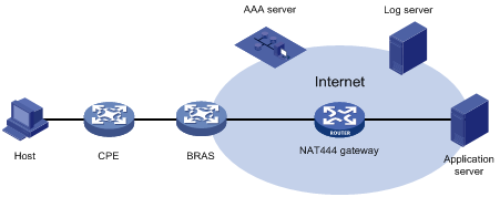
As shown in Figure 10, the NAT444 architecture includes the following entities:
· CPE—Provides NAT services on the customer side.
· BRAS—Provides Internet access services.
· NAT444 gateway—Provides carrier-grade NAT services.
· AAA server—Cooperates with BRAS to provide user authentication, authorization, and accounting services.
· Log server—Records user access logs and responds to queries for user access information.
Figure 10 NAT444 application diagram
The NAT444 gateway provides port block-based PAT translation. It maps multiple private IP addresses to one public IP address and uses a different port block for each private IP address.
For example, the private IP address 10.1.1.1 of an internal host is mapped to the public IP address 202.1.1.1 and port block 10001 to 10256. When the internal host accesses public hosts, the source IP address 10.1.1.1 is translated to 202.1.1.1, and the source ports are translated to ports in the port block 10001 to 10256.
NAT444 includes static NAT444 and dynamic NAT444.
Static NAT444
The NAT444 gateway computes a static NAT444 mapping before address translation. The mapping is between a private IP address and a public IP address with a port block.
The NAT444 gateway uses private IP addresses, public IP addresses, a port range, and a port block size to compute static mappings:
1. Divides the port range by the port block size to get the number of available port blocks for each public IP address.
This value is the base number for mapping.
2. Sorts the port blocks in ascending order of the start port number in each block.
3. Sorts the private IP addresses and the public IP addresses separately in ascending order.
4. Maps the first base number of private IP addresses to the first public IP address and its port blocks in ascending order.
For example, the number of available port blocks of each public IP address is m. The first m private IP addresses are mapped to the first public IP address and the m port blocks in ascending order. The next m private IP addresses are mapped to the second IP address and the m port blocks in ascending order. The other static NAT444 mappings are created by analogy.
Dynamic NAT444
Dynamic NAT444 works as follows:
1. Creates a mapping from the internal host's private IP address to a public IP address and a port block when the host initiates a connection to the public network.
2. Translates the private IP address to the public IP address, and the source ports to ports in the selected port block for subsequent connections from the private IP address.
3. Withdraws the port block and deletes the dynamic NAT444 mapping when all connections from the private IP address are disconnected.
Dynamic NAT444 uses ACLs to implement translation control. It processes only packets that match an ACL permit rule.
Dynamic NAT444 supports port block extending. If the ports in the port block for a private address are all occupied, dynamic NAT444 translates the source port to a port in an extended port block.
Advanced settings
NAT address group
A NAT address group is a set of address ranges. Dynamic NAT uses a NAT address group to translate a larger group of private IP addresses.
NAT444 address group
A NAT444 address group is used to perform dynamic NAT444. A NAT444 address group is similar to a NAT address group. The difference is that a NAT444 address group includes port block parameters, such as a port range, a port block size, and an extended port block number.
Port block group
A port block group is used to perform static NAT444. A port block group includes private IP addresses, public IP addresses, a port range, and a port block size. The NAT444 gateway uses these parameters to calculate static NAT444 mappings and performs NAT444 accordingly.
Internal server group
An internal server group is used to configure load-sharing NAT Server. The internal servers in the group provide the same service to external hosts. When an external host sends a request to the pubic IP address mapped to the internal server group, the NAT device chooses an internal server based on the weight and number of connections of the servers.
PAT
PAT supports the following mappings:
· Endpoint-Independent Mapping—Uses the same IP and port mapping (EIM entry) for packets from the same source IP and port to any destination. EIM allows external hosts to access the internal hosts by using the translated IP address and port. It allows internal hosts behind different NAT gateways to access each other.
· Address and Port-Dependent Mapping—Uses different IP and port mappings for packets from the same source IP and port to different destination IP addresses and ports. APDM allows an external host to access an internal host only under the condition that the internal host has previously accessed the external host. It is secure, but it does not allow internal hosts behind different NAT gateways to access each other.
NAT with DNS mapping
NAT with DNS mapping allows an internal host to access an internal server on the same private network by using the domain name of the internal server when the DNS server is on the public network.
NAT with DNS mapping must operate with NAT Server. DNS mapping maps the domain name to the public IP address, public port number, and protocol type of the internal server. NAT Server maps the public IP and port to the private IP and port of the internal server.
DNS mapping can also be used by DNS ALG. The DNS reply from the external DNS server contains only the domain name and public IP address of the internal server in the payload. The NAT interface might have multiple internal servers configured with the same public IP address but different private IP addresses. DNS ALG might find an incorrect internal server by using only the public IP address. If a DNS mapping is configured, DNS ALG can obtain the public IP address, public port number, and protocol type of the internal server by using the domain name. Then it can find the correct internal server by using the public IP address, public port number, and protocol type of the internal server.
NAT hairpin
NAT hairpin allows internal hosts to access each other through NAT.
NAT hairpin includes P2P and C/S modes:
· P2P—Allows internal hosts to access each other through NAT.
To configure the P2P mode, you must configure outbound PAT on the interface connected to the external network and enable the EIM mapping mode. Internal hosts first register their public addresses to an external server. Then, the hosts communicate with each other by using the registered IP addresses.
· C/S—Allows internal hosts to access internal servers through NAT.
In C/S mode, the source and destination IP address of a packet are translated on the interface connected to the internal network. The destination IP address of the packet going to the internal server is translated by matching the NAT Server configuration. The source IP address is translated by matching the outbound dynamic or static NAT entries.
NAT hairpin typically operates with NAT Server, outbound dynamic NAT, or outbound static NAT. They must be configured on interfaces of the same interface card. Otherwise, NAT hairpin cannot function correctly.
NAT with ALG
NAT with ALG translates address or port information in the application layer payloads to ensure connection establishment.
NAT logging
· NAT session logging
NAT session logging records NAT session information, including translation information, access information, and flow information.
A NAT device generates NAT session logs for the following events:
¡ NAT session establishment.
¡ NAT session removal. This event occurs when you add a configuration with a higher priority, remove a configuration, and change ACLs, when a NAT session ages out, or when you manually delete a NAT session.
¡ Active NAT session logging.
· NAT444 user logging
NAT444 user logs are used for user tracing. The NAT444 gateway generates a user log whenever it assigns or withdraws a port block. The log includes the private IP address, public IP address, and port block. You can use the public IP address and port numbers to locate the user's private IP address from the user logs.
A NAT444 gateway generates NAT user logs when one of the following events occurs:
¡ A port block is assigned.
For static NAT444, the NAT444 gateway generates a user log when it translates the first connection from a private IP address.
For dynamic NAT444, the NAT444 gateway generates a user log when it assigns or extends a port block for a private IP address.
¡ A port block is withdrawn.
For static NAT444, the NAT444 gateway generates a user log when all connections from a private IP address are disconnected.
For dynamic NAT444, the NAT444 gateway generates a user log when all the following conditions are met:
- All connections from a private IP address are disconnected.
- The port blocks (including the extended ones) assigned to the private IP address are withdrawn.
- The corresponding mapping entry is deleted.
· NAT444 alarm logging
If the public IP addresses, port blocks, or ports in selected port blocks (including extended ones) are all occupied, the NAT444 gateway cannot perform address translation and packets will be dropped. To monitor the usage of public IP addresses and port block resources, you can configure NAT444 alarm logging.
A NAT444 gateway generates alarm logs when one of the following occurs:
¡ The ports in the selected port block of a static NAT444 mapping are all occupied.
¡ The ports in the selected port blocks (including extended ones) of a dynamic NAT444 mapping are all occupied.
¡ The public IP addresses and port blocks for dynamic NAT444 are all assigned.
Restrictions and guidelines
When you configure NAT, follow these restrictions and guidelines:
· Do not configure inbound static NAT alone. Typically, inbound static NAT functions with outbound dynamic NAT, NAT Server, or outbound static NAT to implement bidirectional NAT.
· The following shows the priorities of different NAT features in descending order:
¡ NAT Server.
¡ Static NAT.
¡ Static NAT444.
¡ Dynamic NAT and dynamic NAT444.
Dynamic NAT and dynamic NAT444 have the same priority. They are matched in the descending order of ACL numbers.
· The address ranges in a NAT address group cannot overlap with each other.
· The number of IP addresses in a NAT address group cannot be smaller than the number of security engines.
· In an internal server group, an internal server with a larger weight provides a larger percentage of service.
· Before configuring NAT444 user and alarm logging, you must configure the custom NAT444 log generation and outputting functions.
DHCP
The Dynamic Host Configuration Protocol (DHCP) provides a framework to assign configuration information to network devices.
A typical DHCP application scenario has a DHCP server and multiple DHCP clients deployed on the same subnet. DHCP clients can also obtain configuration parameters from a DHCP server on another subnet through a DHCP relay agent.
DHCP server
The DHCP server is well suited to networks where:
· Manual configuration and centralized management are difficult to implement.
· IP addresses are limited. For example, an ISP limits the number of concurrent online users, and users must acquire IP addresses dynamically.
· Most hosts do not need fixed IP addresses.
The DHCP server selects IP addresses and other parameters from an address pool and assigns them to DHCP clients. A DHCP address pool contains the following items:
· Assignable IP addresses.
· Lease duration.
· Gateway addresses.
· Domain name suffix.
· DNS server addresses.
· WINS server addresses.
· NetBIOS node type.
· DHCP options.
Before assigning an IP address, the DHCP server performs IP address conflict detection to verify that the IP address is not in use.
DHCP address pool
The DHCP server supports the following address assignment mechanisms:
· Static address allocation—Manually bind the MAC address or ID of a client to an IP address in a DHCP address pool. When the client requests an IP address, the DHCP server assigns the IP address in the static binding to the client.
· Dynamic address allocation—Specify IP address ranges in a DHCP address pool. Upon receiving a DHCP request, the DHCP server dynamically selects an IP address from the matching IP address range in the address pool.
You can specify the lease duration for IP addresses in the DHCP address pool.
The DHCP server observes the following principles to select an address pool for a client:
· If there is an address pool where an IP address is statically bound to the MAC address or ID of the client, the DHCP server selects this address pool and assigns the statically bound IP address and other configuration parameters to the client.
· If no static address pool is configured, the DHCP server selects an address pool depending on the client location.
¡ Client on the same subnet as the server—The DHCP server compares the IP address of the receiving interface with the subnets of all address pools. If a match is found, the server selects the address pool with the longest-matching subnet.
¡ Client on a different subnet than the server—The DHCP server compares the IP address in the giaddr field of the DHCP request with the subnets of all address pools. If a match is found, the server selects the address pool with the longest-matching subnet.
IP address allocation sequence
The DHCP server selects an IP address for a client in the following sequence:
1. IP address statically bound to the client's MAC address or ID.
2. IP address that was ever assigned to the client.
3. IP address designated by the Option 50 field in the DHCP-DISCOVER message sent by the client. Option 50 is the Requested IP Address option. The client uses this option to specify the wanted IP address in a DHCP-DISCOVER message. The content of Option 50 is user defined.
4. First assignable IP address found in the way of selecting an address pool.
5. IP address that was a conflict or passed its lease duration. If no IP address is assignable, the server does not respond.
DHCP options
DHCP uses the options field to carry information for dynamic address allocation and provide additional configuration information for clients.
You can customize options for the following purposes:
· Add newly released DHCP options.
· Add options for which the vendor defines the contents, for example, Option 43. DHCP servers and clients can use vendor-specific options to exchange vendor-specific configuration information.
· Add options for which the Web interface does not provide a dedicated configuration page. For example, you can use Option 4 to specify the time server address 1.1.1.1 for DHCP clients.
· Add all option values if the actual requirement exceeds the limit for a dedicated option configuration page. For example, on the DNS server configuration page, you can specify up to eight DNS servers. To specify more than eight DNS servers, you can use Option 6 to specify all DNS servers.
The following table shows the most commonly used DHCP options.
|
Option number |
Option name |
Recommended padding format |
|
3 |
Router |
IP address |
|
6 |
Domain Name Server |
IP address |
|
15 |
Domain Name |
ASCII string |
|
44 |
NetBIOS over TCP/IP Name Server |
IP address |
|
46 |
NetBIOS over TCP/IP Node Type |
Hexadecimal string |
|
66 |
TFTP server name |
ASCII string |
|
67 |
Bootfile name |
ASCII string |
|
43 |
Vendor Specific Information |
Hexadecimal string |
IP address conflict detection
Before assigning an IP address, the DHCP server pings the IP address.
· If the server receives a response within the specified period, it selects and pings another IP address.
· If it receives no response, the server continues to ping the IP address until a specific number of ping packets are sent. If still no response is received, the server assigns the IP address to the requesting client.
DHCP relay agent
The DHCP relay agent enables clients to get IP addresses from a DHCP server on another subnet. This feature avoids deploying a DHCP server for each subnet to centralize management and reduce investment.
DHCP relay entry recording
This function enables the DHCP relay agent to automatically record clients' IP-to-MAC bindings (relay entries) after they obtain IP addresses through DHCP.
Some security functions use the relay entries to check incoming packets and block packets that do not match any entry. In this way, illegal hosts are not able to access external networks through the relay agent. Examples of the security functions are ARP address check, authorized ARP, and IP source guard.
Periodic refreshing of dynamic DHCP relay entries
A DHCP client unicasts a DHCP-RELEASE message to the DHCP server to release its IP address. The DHCP relay agent conveys the message to the DHCP server and does not remove the IP-to-MAC entry of the client.
With this feature, the DHCP relay agent uses the following information to periodically send a DHCP-REQUEST message to the DHCP server:
· The IP address of a relay entry.
· The MAC address of the DHCP relay interface.
The relay agent maintains the relay entries depending on what it receives from the DHCP server:
· If the server returns a DHCP-ACK message or does not return any message within an interval, the DHCP relay agent removes the relay entry. In addition, upon receiving the DHCP-ACK message, the relay agent sends a DHCP-RELEASE message to release the IP address.
· If the server returns a DHCP-NAK message, the relay agent keeps the relay entry.
DHCP snooping
DHCP snooping works between the DHCP client and server, or between the DHCP client and DHCP relay agent. DHCP snooping provides the following functions:
· Ensures that DHCP obtain IP addresses only from authorized DHCP servers.
DHCP snooping defines trusted and untrusted ports to make sure clients obtain IP addresses only from authorized DHCP servers.
¡ Trusted—A trusted port can forward DHCP messages correctly to make sure the clients get IP addresses from authorized DHCP servers.
¡ Untrusted—An untrusted port discards received DHCP-ACK and DHCP-OFFER messages to prevent unauthorized servers from assigning IP addresses.
Configure ports facing the DHCP server as trusted ports, and configure other ports as untrusted ports.
· Records DHCP snooping entries.
DHCP snooping reads DHCP-ACK messages received from trusted ports and DHCP-REQUEST messages to create DHCP snooping entries. A DHCP snooping entry includes the MAC and IP addresses of a client, the port that connects to the DHCP client, and the VLAN. ARP detection uses DHCP snooping entries to filter ARP packets from unauthorized clients.
· Backs up DHCP snooping entries automatically.
The auto backup function saves DHCP snooping entries to a backup file, and allows the DHCP snooping device to download the entries from the backup file at device reboot. The entries on the DHCP snooping device cannot survive a reboot. The auto backup helps some other features provide services if these features must use DHCP snooping entries for user authentication.
· Supports Option 82.
Option 82 records the location information about the DHCP client so the administrator can locate the DHCP client for security and accounting purposes. Option 82 contains two sub-options: Circuit ID and Remote ID.
If the DHCP relay agent supports Option 82, it handles DHCP requests by the strategies described in the following table.
If a response returned by the DHCP server contains Option 82, DHCP snooping removes Option 82 before forwarding the response to the client. If the response contains no Option 82, DHCP snooping forwards it directly.
The following table shows the Option 82 handling strategies for DHCP requests:
|
If a DHCP request has… |
Handling strategy |
DHCP snooping… |
|
Option 82 |
Drop |
Drops the message. |
|
Keep |
Forwards the message without changing Option 82. |
|
|
Replace |
Forwards the message after replacing the original Option 82 with the Option 82 padded according to the configured padding format, padding content, and code type. |
|
|
No Option 82 |
N/A |
Forwards the message after adding the Option 82 padded according to the configured padding format, padding content, and code type. |
DNS
Domain Name System (DNS) is a distributed database used by TCP/IP applications to translate domain names into IP addresses. IPv4 DNS translates domain names into IPv4 addresses. IPv6 DNS translates domain names into IPv6 addresses. The domain name-to-IP address mapping is called a DNS entry.
Dynamic domain name resolution
To use dynamic domain name resolution, you must specify a DNS server address for a device. The device sends DNS queries to the DNS server for domain name resolution.
You can configure a domain name suffix list so that the resolver can use the list to supply the missing part of an incomplete name. For example, you can configure com as the suffix for aabbcc.com. The user only needs to enter aabbcc to obtain the IP address of aabbcc.com. The resolver adds the suffix and delimiter before passing the name to the DNS server.
The name resolver handles the queries based on the domain names that the user enters:
· If the user enters a domain name without a dot (.) (for example, aabbcc), the resolver considers the domain name as a host name. It adds a DNS suffix to the host name before performing the query operation. If no match is found for any host name and suffix combination, the resolver uses the user-entered domain name (for example, aabbcc) for the IP address query.
· If the user enters a domain name with a dot (.) among the letters (for example, www.aabbcc), the resolver directly uses this domain name for the query operation. If the query fails, the resolver adds a DNS suffix for another query operation.
· If the user enters a domain name with a dot (.) at the end (for example, aabbcc.com.), the resolver considers the domain name an FQDN and returns the successful or failed query result. The dot at the end of the domain name is considered a terminating symbol.
Static domain name resolution
Static domain name resolution means manually creating mappings between domain names and IP addresses. For example, you can create a static DNS mapping for a device so that you can Telnet to the device by using the domain name.
After a user specifies a name, the device checks the static name resolution table for an IP address. If no IP address is available, it contacts the DNS server for dynamic name resolution, which takes more time than static name resolution. To improve efficiency, you can put frequently queried name-to-IP address mappings in the local static name resolution table.
DNS proxy
The DNS proxy performs the following operations:
· Forwards the request from the DNS client to the designated DNS server.
· Conveys the reply from the DNS server to the client.
The DNS proxy simplifies network management. When the DNS server address is changed, you can change the configuration on only the DNS proxy instead of on each DNS client.
DDNS
The following matrix shows the feature and hardware compatibility:
|
Hardware series |
Model |
DDNS compatibility |
|
WX1800H series |
WX1804H WX1810H WX1820H WX1840H |
Yes |
|
WX3800H series |
WX3820H WX3840H |
No |
|
WX5800H series |
WX5860H |
No |
DNS provides only the static mappings between domain names and IP addresses. When the IP address of a node changes, your access to the node fails.
Dynamic Domain Name System (DDNS) can dynamically update the mappings between domain names and IP addresses for DNS servers.
To use DDNS, a user must access the website of a DDNS service provider and register an account. When its IP address changes, the user, as a DDNS client, sends a DDNS update request to the DDNS server to update the mapping between its domain name and IP address. When receiving the update request, the DDNS server verifies the following:
· The account information is correct.
· The domain name to be updated belongs to the account.
If the DDNS client passes the verification, the DDNS server tells the DNS server to re-map the domain name and the IP address of the DDNS client.
A DDNS policy contains the DDNS server address, login ID, password, associated SSL client policy, and update time interval. After creating a DDNS policy, you can apply it to multiple interfaces to simplify DDNS configuration.
DDNS is supported by only IPv4 DNS, and it is used to update the mappings between domain names and IPv4 addresses.
IGMP snooping
IGMP snooping runs on a Layer 2 device as a multicast constraining mechanism. It creates Layer 2 multicast forwarding entries from IGMP packets that are exchanged between the hosts and the Layer 3 device.
The Layer 2 device forwards multicast data based on Layer 2 multicast forwarding entries. A Layer 2 multicast forwarding entry contains the VLAN, multicast group address, multicast source address, and host ports. A host port is a multicast receiver-side port on the Layer 2 multicast device.
MLD snooping
MLD snooping runs on a Layer 2 device as an IPv6 multicast constraining mechanism. It creates Layer 2 IPv6 multicast forwarding entries from MLD packets that are exchanged between the hosts and the Layer 3 device.
The Layer 2 device forwards multicast data based on Layer 2 IPv6 multicast forwarding entries. A Layer 2 IPv6 multicast forwarding entry contains the VLAN, IPv6 multicast group address, IPv6 multicast source address, and host ports. A host port is a multicast receiver-side port on the Layer 2 multicast device.
ARP
ARP resolves IP addresses into MAC addresses on Ethernet networks.
Types of ARP table entries
An ARP table stores dynamic and static ARP entries.
Dynamic ARP entry
ARP automatically creates and updates dynamic entries. A dynamic ARP entry is removed when its aging timer expires or the output interface goes down. In addition, a dynamic ARP entry can be overwritten by a static ARP entry.
Dynamic ARP entries can be converted to static ARP entries. These static ARP entries cannot be converted back to dynamic entries.
To prevent an interface from holding too many ARP entries, you can set the maximum number of dynamic ARP entries that the interface can learn.
Static ARP entry
A static ARP entry is manually configured or converted from a dynamic ARP entry. It does not age out and cannot be overwritten by any dynamic ARP entry.
Static ARP entries protect communication between devices because attack packets cannot modify the IP-to-MAC mapping in a static ARP entry.
To communicate with a host by using a fixed IP-to-MAC mapping, configure a static ARP entry on the device.
To communicate with a host by using a fixed IP-to-MAC mapping through an interface in a VLAN, you need to specify the VLAN and the output interface in the ARP entry. Make sure the IP address is on the same subnet as the IP address of the VLAN interface.
Proxy ARP
Proxy ARP enables a device on one network to answer ARP requests for an IP address on another network. With proxy ARP, hosts on different broadcast domains can communicate with each other as they would on the same broadcast domain.
Proxy ARP includes common proxy ARP and local proxy ARP.
· Common proxy ARP—Allows communication between hosts that connect to different Layer 3 interfaces and reside in different broadcast domains.
· Local proxy ARP—Allows communication between hosts that connect to the same Layer 3 interface and reside in different broadcast domains.
You can specify an IP address range for which local proxy ARP is enabled.
Gratuitous ARP
In a gratuitous ARP packet, the sender IP address and the target IP address are the IP address of the sending device.
A device sends a gratuitous ARP packet for either of the following purposes:
· Determine whether its IP address is already used by another device. If the IP address is already used, the device is informed of the conflict by an ARP reply.
· Inform other devices of a MAC address change.
Gratuitous ARP packet learning
This function enables a device to create or update ARP entries by using the sender IP and MAC addresses in received gratuitous ARP packets.
When this function is disabled, the device uses received gratuitous ARP packets to update existing ARP entries only. ARP entries are not created based on the received gratuitous ARP packets, which saves ARP table space.
Replying with gratuitous ARP packets
This function enables a device to send gratuitous ARP packets upon receiving ARP requests whose sender IP address is on a different subnet.
Periodic sending of gratuitous ARP packets
Enabling periodic sending of gratuitous ARP packets helps downstream devices update ARP entries or MAC entries in a timely manner.
This feature can implement the following functions:
· Prevent gateway spoofing.
Gateway spoofing occurs when an attacker uses the gateway address to send gratuitous ARP packets to the hosts on a network. The traffic destined for the gateway from the hosts is sent to the attacker instead. As a result, the hosts cannot access the external network.
To prevent such gateway spoofing attacks, you can enable the gateway to send gratuitous ARP packets at intervals. Gratuitous ARP packets contain the primary IP address and manually configured secondary IP addresses of the gateway, so hosts can learn correct gateway information.
· Prevent ARP entries from aging out.
If network traffic is heavy or if the host CPU usage is high, received ARP packets can be discarded or are not promptly processed. Eventually, the dynamic ARP entries on the receiving host age out. The traffic between the host and the corresponding devices is interrupted until the host re-creates the ARP entries.
To prevent this problem, you can enable the gateway to send gratuitous ARP packets periodically. Gratuitous ARP packets contain the primary IP address and manually configured secondary IP addresses of the gateway, so the receiving hosts can update ARP entries in a timely manner.
ARP attack protection
ARP attacks and viruses are threatening LAN security. Although ARP is easy to implement, it provides no security mechanism and is vulnerable to network attacks. Multiple features are used to detect and prevent ARP attacks.
· The gateway supports the following features:
¡ ARP blackhole routing.
¡ ARP source suppression.
¡ ARP packet source MAC consistency check.
¡ ARP active acknowledgement.
¡ Source MAC-based ARP attack detection.
¡ Authorized ARP.
¡ ARP scanning and fixed ARP.
· The access device supports the following features:
¡ ARP gateway protection.
¡ ARP filtering.
¡ ARP detection.
Unresolvable IP attack protection
If a device receives a large number of unresolvable IP packets from a host, the following situations can occur:
· The device sends a large number of ARP requests, overloading the target subnets.
· The device keeps trying to resolve the destination IP addresses, overloading its CPU.
To protect the device from such IP attacks, you can configure the following features:
· ARP source suppression—Stops resolving packets from a host if the number of unresolvable IP packets from the host exceeds the upper limit within 5 seconds. The device continues ARP resolution when the interval elapses. This feature is applicable if the attack packets have the same source addresses.
· ARP blackhole routing—Creates a blackhole route destined for an unresolvable IP address. The device drops all matching packets until the blackhole route ages out. This feature is applicable regardless of whether the attack packets have the same source addresses.
ARP packet source MAC consistency check
This feature enables a gateway to filter out ARP packets whose source MAC address in the Ethernet header is different from the sender MAC address in the message body. This feature allows the gateway to learn correct ARP entries.
ARP active acknowledgement
Configure this feature on gateways to prevent user spoofing.
ARP active acknowledgement prevents a gateway from generating incorrect ARP entries.
In strict mode, a gateway performs more strict validity checks before creating an ARP entry:
· Upon receiving an ARP request destined for the gateway, the gateway sends an ARP reply but does not create an ARP entry.
· Upon receiving an ARP reply, the gateway determines whether it has resolved the sender IP address:
¡ If yes, the gateway performs active acknowledgement. When the ARP reply is verified as valid, the gateway creates an ARP entry.
¡ If not, the gateway discards the packet.
Source MAC-based ARP attack detection
This feature checks the number of ARP packets delivered to the CPU. If the number of packets from the same MAC address within 5 seconds exceeds a threshold, the device adds the MAC address to an ARP attack entry. Before the entry is aged out, the device handles the attack by using either of the following methods:
· Monitor—Only generates log messages.
· Filter—Generates log messages and filters out subsequent ARP packets from that MAC address.
You can exclude the MAC addresses of some gateways and servers from this detection. This feature does not inspect ARP packets from those devices even if they are attackers.
Authorized ARP
Authorized ARP entries are generated based on the DHCP clients' address leases on the DHCP server or dynamic client entries on the DHCP relay agent.
With authorized ARP enabled, an interface is disabled from learning dynamic ARP entries. This feature prevents user spoofing and allows only authorized clients to access network resources.
ARP scanning and fixed ARP
ARP scanning is typically used together with the fixed ARP feature in small-scale networks.
ARP scanning automatically creates ARP entries for devices in an address range. The device performs ARP scanning using the following steps:
1. Sends ARP requests for each IP address in the address range.
2. Obtains their MAC addresses through received ARP replies.
3. Creates dynamic ARP entries.
Fixed ARP converts existing dynamic ARP entries (including those generated through ARP scanning) to static ARP entries. This feature prevents ARP entries from being modified by attackers.
ARP gateway protection
Configure this feature on interfaces not connected with a gateway to prevent gateway spoofing attacks.
When such an interface receives an ARP packet, it checks whether the sender IP address in the packet is consistent with that of any protected gateway. If yes, it discards the packet. If not, it handles the packet correctly.
ARP filtering
The ARP filtering feature can prevent gateway spoofing and user spoofing attacks.
An interface enabled with this feature checks the sender IP and MAC addresses in a received ARP packet against permitted entries. If a match is found, the packet is handled correctly. If not, the packet is discarded.
ARP detection
ARP detection enables access devices to block ARP packets from unauthorized clients to prevent user spoofing and gateway spoofing attacks. ARP detection does not check ARP packets received from ARP trusted ports.
ARP detection provides the following functions:
· User validity check
If you only enable ARP detection for a VLAN, ARP detection provides only the user validity check.
Upon receiving an ARP packet from an ARP untrusted interface, the device matches the sender IP and MAC addresses with the following entries:
¡ Static IP source guard binding entries.
¡ DHCP snooping entries.
If a match is found, the ARP packet is considered valid and is forwarded. If no match is found, the ARP packet is considered invalid and is discarded.
· ARP packet validity check
Enable validity check for ARP packets received on untrusted ports and specify the following objects to be checked:
¡ Sender MAC—Checks whether the sender MAC address in the message body is identical to the source MAC address in the Ethernet header. If they are identical, the packet is forwarded. Otherwise, the packet is discarded.
¡ Target MAC—Checks the target MAC address of ARP replies. If the target MAC address is all-zero, all-one, or inconsistent with the destination MAC address in the Ethernet header, the packet is considered invalid and discarded.
¡ IP—Checks the sender and target IP addresses of ARP replies, and the sender IP address of ARP requests. All-one or multicast IP addresses are considered invalid and the corresponding packets are discarded.
· ARP restricted forwarding
ARP restricted forwarding controls the forwarding of ARP packets that are received on untrusted interfaces and have passed user validity check as follows:
¡ If the packets are ARP requests, they are forwarded through the trusted interface.
¡ If the packets are ARP replies, they are forwarded according to their destination MAC address. If no match is found in the MAC address table, they are forwarded through the trusted interface.
ND
The IPv6 Neighbor Discovery (ND) protocol uses ICMPv6 messages to provide the following functions:
· Address resolution
· Neighbor reachability detection
· DAD
· Router/prefix discovery
· Stateless address autoconfiguration
· Redirection
Table 15 describes the ICMPv6 messages used by ND.
Table 15 ICMPv6 messages used by ND
|
ICMPv6 message |
Type |
Function |
|
Neighbor Solicitation (NS) |
135 |
Acquires the link-layer address of a neighbor. |
|
Verifies whether a neighbor is reachable. |
||
|
Detects duplicate addresses. |
||
|
Neighbor Advertisement (NA) |
136 |
Responds to an NS message. |
|
Notifies the neighboring nodes of link layer changes. |
||
|
Router Solicitation (RS) |
133 |
Requests an address prefix and other configuration information for autoconfiguration after startup. |
|
Router Advertisement (RA) |
134 |
Responds to an RS message. |
|
Advertises information, such as the Prefix Information options and flag bits. |
||
|
Redirect |
137 |
Informs the source host of a better next hop on the path to a particular destination when certain conditions are met. |
Neighbor entries
A neighbor entry stores information about a neighboring node on the link. Neighbor entries can be dynamically configured through NS and NA messages or manually configured.
You can configure a static neighbor entry by using one of the following methods:
· Method 1—Associate a neighbor's IPv6 address and link-layer address with the local Layer 3 interface.
If you use Method 1, the device automatically finds the Layer 2 port connected to the neighbor.
· Method 2—Associate a neighbor's IPv6 address and link-layer address with a Layer 2 port in a VLAN.
If you use Method 2, make sure the corresponding VLAN interface exists and the Layer 2 port belongs to the VLAN.
RA messages
An RA message is advertised by a router to all hosts on the same link. The RA message contains the address prefix and other configuration information for the hosts to generate IPv6 addresses through stateless address autoconfiguration.
You can enable an interface to send RA messages, specify the maximum and minimum sending intervals and configure parameters in RA messages. The device sends RA messages at random intervals between the maximum and minimum intervals. The minimum interval should be less than or equal to 0.75 times the maximum interval.
Table 16 describes the configurable parameters in an RA message.
Table 16 Parameters in an RA message and their descriptions
|
Parameter |
Description |
|
IPv6 prefix/prefix length |
The IPv6 prefix/prefix length for a host to generate an IPv6 global unicast address through stateless autoconfiguration. |
|
Valid lifetime |
Specifies the valid lifetime of a prefix. The generated IPv6 address is valid within the valid lifetime and becomes invalid when the valid lifetime expires. |
|
Preferred lifetime |
Specifies the preferred lifetime of a prefix used for stateless autoconfiguration. After the preferred lifetime expires, the node cannot use the generated IPv6 address to establish new connections, but can receive packets destined for the IPv6 address. The preferred lifetime cannot be greater than the valid lifetime. |
|
No-autoconfig flag |
Tells the hosts not to use the address prefix for stateless autoconfiguration. |
|
Off-link flag |
Specifies the address with the prefix to be indirectly reachable on the link. |
|
MTU |
Guarantees that all nodes on the link use the same MTU. |
|
Unlimited hops flag |
Specifies unlimited hops in RA messages. |
|
M flag |
Determines whether a host uses stateful autoconfiguration to obtain an IPv6 address. If the M flag is set, the host uses stateful autoconfiguration (for example, from a DHCPv6 server) to obtain an IPv6 address. If the flag is not set, the host uses stateless autoconfiguration to generate an IPv6 address according to its link-layer address and the prefix information in the RA message. |
|
O flag |
Determines whether a host uses stateful autoconfiguration to obtain configuration information other than IPv6 address. If the O flag is set, the host uses stateful autoconfiguration (for example, from a DHCPv6 server) to obtain configuration information other than IPv6 address. If the flag is not set, the host uses stateless autoconfiguration. |
|
Router Lifetime |
Advertises the lifetime of an advertising router. If the lifetime is 0, the router cannot be used as the default gateway. |
|
Retrans Timer |
Specifies the interval for retransmitting the NS message after the device does not receive a response for an NS message within a time period. |
|
Router Preference |
Specifies the router preference in an RA message. A host selects a router as the default gateway according to the router preference. If router preferences are the same, the host selects the router from which the first RA message is received. |
|
Reachable Time |
Specifies the reachable period for a neighbor after the device detects that a neighbor is reachable. If the device needs to send a packet to the neighbor after the reachable period, the device reconfirms whether the neighbor is reachable. |
ND proxy
ND proxy enables a device to answer an NS message requesting the hardware address of a host on another network. With ND proxy, hosts in different broadcast domains can communicate with each other as they would on the same network.
ND proxy includes common ND proxy and local ND proxy.
Common ND proxy
As shown in Figure 11, Interface A with IPv6 address 4:1::96/64 and Interface B with IPv6 address 4:2::99/64 belong to different subnets. Host A and Host reside on the same network but in different broadcast domains.
Figure 11 Application environment of common ND proxy
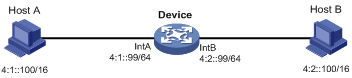
Because Host A's IPv6 address is on the same subnet as Host B's, Host A directly sends an NS message to obtain Host B's MAC address. However, Host B cannot receive the NS message because they belong to different broadcast domains.
To solve this problem, enable common ND proxy on Interface A and Interface B of the Device. The Device replies to the NS message from Host A, and forwards packets from other hosts to Host B.
Local ND proxy
As shown in Figure 12, Host A belongs to VLAN 2 and Host B belongs to VLAN 3. Host A and Host B connect to Interface A and Interface C, respectively.
Figure 12 Application environment of local ND proxy
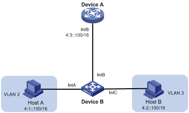
Because Host A's IPv6 address is on the same subnet as Host B's, Host A directly sends an NS message to obtain Host B's MAC address. However, Host B cannot receive the NS message because they are in different VLANs.
To solve this problem, enable local ND proxy on Interface B of the router so that the router can forward messages between Host A and Host B.
HTTP/HTTPS
The device provides a built-in Web server. After you enable the Web server on the device, users can log in to the Web interface to manage and monitor the device.
The device's built-in Web server supports both Hypertext Transfer Protocol (HTTP) (version 1) and Hypertext Transfer Protocol Secure (HTTPS). HTTPS is more secure than HTTP because of the following items:
· HTTPS uses SSL to ensure the integrity and security of data exchanged between the client and the server.
· HTTPS allows you to define a certificate attribute-based access control policy to allow only legal clients to access the Web interface.
You can also specify a basic ACL for HTTP or HTTPS to prevent unauthorized Web access.
· If you do not specify an ACL for HTTP or HTTPS, or the specified ACL does not exist or does not have rules, the device permits all HTTP or HTTPS logins.
· If the specifies ACL has rules, only users permitted by the ACL can log in to the Web interface through HTTP or HTTPS.
FTP
File Transfer Protocol (FTP) is an application layer protocol for transferring files from one host to another over an IP network. It uses TCP port 20 to transfer data and TCP port 21 to transfer control commands.
The device can act as the FTP server.
Telnet
The device can act as a Telnet server to allow Telnet login. After you configure Telnet service on the device, users can remotely log in to the device to manage and monitor the device.
To prevent unauthorized Telnet logins, you can use ACLs to filter Telnet logins.
· If you do not specify an ACL for Telnet service, or the specified ACL does not exist or does not have rules, the device permits all Telnet logins.
· If the specified ACL has rules, only users permitted by the ACL can Telnet to the device.
SSH
Secure Shell (SSH) is a network security protocol. Using encryption and authentication, SSH can implement secure remote access and file transfer over an insecure network.
SSH uses the typical client-server model to establish a channel for secure data transfer based on TCP.
The device can act as an SSH server and provide the following services for SSH clients:
· Secure Telnet—Stelnet provides secure and reliable network terminal access services.
· Secure FTP—SFTP uses SSH connections to provide secure file transfer based on SSH2.
· Secure Copy—SCP offers a secure method to copy files based on SSH2.
SSH includes two versions: SSH1.x and SSH2.0 (hereinafter referred to as SSH1 and SSH2), which are not compatible. SSH2 provides better performance and security than SSH1. In non-FIPS mode, the device that acts as an SSH server supports both SSH2 and SSH1. In FIPS mode, it supports only SSH2.
When the device acts as an SSH server, it supports using local password authentication to examine the validity of the username and password of an SSH client. After the SSH client passes the authentication, the two parties establish a session for data exchange.
NTP
Synchronize your device with a trusted time source by using the Network Time Protocol (NTP) or changing the system time before you run it on a live network.
NTP uses stratum to define the accuracy of each server. The value is in the range of 1 to 15. A smaller value represents a higher accuracy.
If the devices in a network cannot synchronize to an authoritative time source, you can perform the following tasks:
· Select a device that has a relatively accurate clock from the network.
· Use the local clock of the device as the reference clock to synchronize other devices in the network.
You can configure the local clock as a reference clock in the Web interface.
LLDP
The Link Layer Discovery Protocol (LLDP) operates on the data link layer to exchange device information between directly connected devices. With LLDP, a device sends local device information as TLV (type, length, and value) triplets in LLDP Data Units (LLDPDUs) to the directly connected devices. Local device information includes its system capabilities, management IP address, device ID, port ID, and so on. The device stores the device information in LLDPDUs from the LLDP neighbors in a standard MIB. LLDP enables a network management system to quickly detect and identify Layer 2 network topology changes.
LLDP agent
An LLDP agent is a mapping of an entity where LLDP runs. Multiple LLDP agents can run on the same interface.
LLDP agents are divided into the following types:
· Nearest bridge agent.
· Nearest customer bridge agent.
· Nearest non-TPMR bridge agent.
LLDP exchanges packets between neighbor agents and creates and maintains neighbor information for them.
Transmitting LLDP frames
An LLDP agent operating in TxRx mode or Tx mode sends LLDP frames to its directly connected devices both periodically and when the local configuration changes. To prevent LLDP frames from overwhelming the network during times of frequent changes to local device information, LLDP uses the token bucket mechanism to rate limit LLDP frames.
LLDP automatically enables the fast LLDP frame transmission mechanism in either of the following cases:
· A new LLDP frame is received and carries device information new to the local device.
· The LLDP operating mode of the LLDP agent changes from Disable or Rx to TxRx or Tx.
The fast LLDP frame transmission mechanism successively sends the specified number of LLDP frames at a configurable fast LLDP frame transmission interval. The mechanism helps LLDP neighbors discover the local device as soon as possible. Then, the normal LLDP frame transmission interval resumes.
Receiving LLDP frames
An LLDP agent operating in TxRx mode or Rx mode confirms the validity of TLVs carried in every received LLDP frame. If the TLVs are valid, the LLDP agent saves the information and starts an aging timer. When the TTL value in the Time To Live TLV carried in the LLDP frame becomes zero, the information ages out immediately.
By setting the TTL multiplier, you can configure the TTL of locally sent LLDPDUs. The TTL is expressed by using the following formula:
TTL = Min (65535, (TTL multiplier × LLDP frame transmission interval + 1))
As the expression shows, the TTL can be up to 65535 seconds. TTLs greater than 65535 will be rounded down to 65535 seconds.
LLDP reinitialization delay
When the LLDP operating mode changes on a port, the port initializes the protocol state machines after an LLDP reinitialization delay. By adjusting the delay, you can avoid frequent initializations caused by frequent changes to the LLDP operating mode on a port.
LLDP trapping
LLDP trapping notifies the network management system of events such as newly detected neighboring devices and link failures.
LLDP TLVs
A TLV is an information element that contains the type, length, and value fields. LLDPDU TLVs include the following categories:
· Basic management TLVs
· Organizationally (IEEE 802.1 and IEEE 802.3) specific TLVs
· LLDP-MED (media endpoint discovery) TLVs
Basic management TLVs are essential to device management.
Organizationally specific TLVs and LLDP-MED TLVs are used for enhanced device management. They are defined by standardization or other organizations and are optional for LLDPDUs.
Log
Log levels
Logs are classified into eight severity levels from 0 through 7 in descending order.
Table 17 Log levels
|
Severity value |
Level |
Description |
|
0 |
Emergency |
The system is unusable. For example, the system authorization has expired. |
|
1 |
Alert |
Action must be taken immediately. For example, traffic on an interface exceeds the upper limit. |
|
2 |
Critical |
Critical condition. For example, the device temperature exceeds the upper limit, the power module fails, or the fan tray fails. |
|
3 |
Error |
Error condition. For example, the link state changes or a storage card is unplugged. |
|
4 |
Warning |
Warning condition. For example, an interface is disconnected, or the memory resources are used up. |
|
5 |
Notification |
Normal but significant condition. For example, a terminal logs in to the device, or the device reboots. |
|
6 |
Informational |
Informational message. For example, a command or a ping operation is executed. |
|
7 |
Debugging |
Debug message. |
Log destinations
The system outputs logs to destinations such as the log buffer and log host. Log output destinations are independent and you can configure them in the Web interface.
Security features
Packet filter
Packet filter uses ACLs to filter incoming or outgoing packets on interfaces, VLANs, or globally. An interface permits packets that match permit statements to pass through, and denies packets that match deny statements. The default action applies to packets that do not match any ACL rules.
QoS
QoS policies
In data communications, Quality of Service (QoS) provides differentiated service guarantees for diversified traffic in terms of bandwidth, delay, jitter, and drop rate, all of which can affect QoS.
By associating a traffic behavior with a traffic class in a QoS policy, you apply QoS actions in the traffic behavior to the traffic class.
Traffic class
A traffic class defines a set of match criteria for classifying traffic.
Traffic behavior
A traffic behavior defines a set of QoS actions to take on packets.
QoS policy
A QoS policy associates traffic classes with traffic behaviors and performs the actions in each behavior on its associated traffic class.
Applying a QoS policy
You can apply a QoS policy to the following destinations:
· Interface—The QoS policy takes effect on the traffic sent or received on the interface. The QoS policy applied to the outgoing traffic on an interface or PVC does not regulate local packets. Local packets refer to critical protocol packets sent by the local system for operation maintenance. The most common local packets include link maintenance and SSH packets.
· Globally—The QoS policy takes effect on the traffic sent or received on all ports.
Priority mapping
When a packet arrives, a device assigns values of priority parameters to the packet for the purpose of queue scheduling and congestion control.
Priority mapping allows you to modify the priority values of the packet according to priority mapping rules. The priority parameters decide the scheduling priority and forwarding priority of the packet.
Port priority
When a port is configured with a priority trust mode, the device trusts the priorities included in incoming packets. The device can automatically resolves the priorities or flag bits included in packets. The device then maps the trusted priority to the target priority types and values according to the priority maps.
When a port is not configured with a priority trust mode and is configured with a port priority, the device does not trust the priorities included in incoming packets. The device uses its port priority to look for priority parameters for the incoming packets.
The available priority trust modes include the following types:
· Untrust—Does not trust any priority included in packets.
· Dot1p—Trusts the 802.1p priorities included in packets.
· DSCP—Trusts the DSCP priorities included in IP packets.
Priority map
The device provides three priority maps: 802.1p-lp, DSCP-802.1p, and DSCP-DSCP. If a default priority map cannot meet your requirements, you can modify the priority map as required.
802.1X
802.1X is a port-based network access control protocol that controls network access by authenticating the devices connected to 802.1X-enabled LAN ports.
802.1X architecture
802.1X includes the following entities:
· Client—A user terminal seeking access to the LAN. The terminal must have 802.1X software to authenticate to the access device.
· Access device—Authenticates the client to control access to the LAN. In a typical 802.1X environment, the access device uses an authentication server to perform authentication.
· Authentication server—Provides authentication services for the access device. The authentication server first authenticates 802.1X clients by using the data sent from the access device. Then, the server returns the authentication results to the access device to make access decisions. The authentication server is typically a RADIUS server. In a small LAN, you can use the access device as the authentication server.
802.1X authentication methods
The access device can perform EAP relay or EAP termination to communicate with the RADIUS server.
· EAP termination—The access device performs the following operations in EAP termination mode:
a. Terminates the EAP packets received from the client.
b. Encapsulates the client authentication information in standard RADIUS packets.
c. Uses PAP or CHAP to authenticate to the RADIUS server.
CHAP does not send plaintext password to the RADIUS server, and PAP sends plaintext password to the RADIUS server.
· EAP relay—The access device uses EAPOR packets to send authentication information to the RADIUS server.
Access control methods
Comware implements port-based access control as defined in the 802.1X protocol, and extends the protocol to support MAC-based access control.
· Port-based access control—Once an 802.1X user passes authentication on a port, all subsequent users can access the network through the port without authentication. When the authenticated user logs off, all other users are logged off.
· MAC-based access control—Each user is separately authenticated on a port. When a user logs off, no other online users are affected.
Port authorization state
The port authorization state determines whether the client is granted access to the network. You can control the authorization state of a port by using the following options:
· Authorized—Places the port in the authorized state, enabling users on the port to access the network without authentication.
· Unauthorized—Places the port in the unauthorized state, denying any access requests from users on the port.
· Auto—Places the port initially in unauthorized state to allow only EAPOL packets to pass. After a user passes authentication, sets the port in the authorized state to allow access to the network. You can use this option in most scenarios.
Periodic online user reauthentication
Periodic online user reauthentication tracks the connection status of online users, and updates the authorization attributes assigned by the server. The attributes include the ACL, VLAN, and user profile-based QoS. The reauthentication interval is user configurable.
Online user handshake
The online user handshake feature checks the connectivity status of online 802.1X users. The access device sends handshake messages to online users at the handshake interval. If the device does not receive any responses from an online user after it has made the maximum handshake attempts, the device sets the user to offline state.
You can also enable the online user handshake security feature to check authentication information in the handshake packets from clients. With this feature, the device prevents 802.1X users who use illegal client software from bypassing iNode security check such as dual network interface cards (NICs) detection.
Authentication trigger
The access device initiates authentication, if a client cannot send EAPOL-Start packets. One example is the 802.1X client available with Windows XP.
The access device supports the following modes:
· Unicast trigger mode—Upon receiving a frame from an unknown MAC address, the access device sends an Identity EAP-Request packet out of the receiving port to the MAC address. The device retransmits the packet if no response has been received within the specified interval.
· Multicast trigger mode—The access device multicasts Identity EAP-Request packets periodically (every 30 seconds by default) to initiate 802.1X authentication.
Auth-Fail VLAN
The 802.1X Auth-Fail VLAN on a port accommodates users who have failed 802.1X authentication because of the failure to comply with the organization security strategy. For example, the VLAN accommodates users who have entered a wrong password. The Auth-Fail VLAN does not accommodate 802.1X users who have failed authentication for authentication timeouts or network connection problems.
The access device handles VLANs on an 802.1X-enabled port based on its 802.1X access control method.
· On a port that performs port-based access control:
|
Authentication status |
VLAN manipulation |
|
A user accesses the port and fails 802.1X authentication. |
The device assigns the Auth-Fail VLAN to the port as the PVID. All 802.1X users on this port can access only resources in the Auth-Fail VLAN. |
|
A user in the 802.1X Auth-Fail VLAN fails 802.1X reauthentication |
The Auth-Fail VLAN is still the PVID on the port, and all 802.1X users on this port are in this VLAN. |
|
A user passes 802.1X authentication. |
· The device assigns the authorization VLAN of the user to the port as the PVID, and it removes the port from the Auth-Fail VLAN. After the user logs off, the guest VLAN is assigned to the port as the PVID. If no guest VLAN is configured, the initial PVID of the port is restored. · If the authentication server does not authorize a VLAN, the initial PVID of the port applies. The user and all subsequent 802.1X users are assigned to the initial PVID. After the user logs off, the PVID remains unchanged. |
· On a port that performs MAC-based access control:
|
Authentication status |
VLAN manipulation |
|
A user fails 802.1X authentication. |
The device maps the MAC address of the user to the 802.1X Auth-Fail VLAN. The user can access only resources in the Auth-Fail VLAN. |
|
A user in the 802.1X Auth-Fail VLAN fails 802.1X reauthentication. |
The user is still in the Auth-Fail VLAN. |
|
A user in the 802.1X Auth-Fail VLAN passes 802.1X authentication. |
The device remaps the MAC address of the user to the authorization VLAN. If the authentication server does not authorize a VLAN, the device remaps the MAC address of the user to the initial PVID on the port. |
Guest VLAN
The 802.1X guest VLAN on a port accommodates users who have not performed 802.1X authentication. Once a user in the guest VLAN passes 802.1X authentication, it is removed from the guest VLAN and can access authorized network resources.
The access device handles VLANs on an 802.1X-enabled port based on its 802.1X access control method.
· On a port that performs port-based access control:
|
Authentication status |
VLAN manipulation |
|
A user accesses the 802.1X-enabled port when the port is in auto state. |
The device assigns the 802.1X guest VLAN to the port as the PVID. All 802.1X users on this port can access only resources in the guest VLAN. If no 802.1X guest VLAN is configured, the access device does not perform any VLAN operation. |
|
A user in the 802.1X guest VLAN fails 802.1X authentication. |
If an 802.1X Auth-Fail VLAN (see "Auth-Fail VLAN") is available, the device assigns the Auth-Fail VLAN to the port as the PVID. All users on this port can access only resources in the Auth-Fail VLAN. If no Auth-Fail VLAN is configured, the PVID on the port is still the 802.1X guest VLAN. All users on the port are in the guest VLAN. |
|
A user in the 802.1X guest VLAN passes 802.1X authentication. |
· The device assigns the authorization VLAN of the user to the port as the PVID, and it removes the port from the 802.1X guest VLAN. After the user logs off, the initial PVID of the port is restored. · If the authentication server does not authorize a VLAN, the initial PVID applies. The user and all subsequent 802.1X users are assigned to the initial port VLAN. After the user logs off, the port VLAN remains unchanged. NOTE: The initial PVID of an 802.1X-enabled port refers to the PVID used by the port before the port is assigned to any 802.1X VLANs. |
· On a port that performs MAC-based access control:
|
Authentication status |
VLAN manipulation |
|
A user has not passed 802.1X authentication and is in the authentication process. |
The device creates a mapping between the MAC address of the user and the 802.1X guest VLAN. The user can access only resources in the guest VLAN. |
|
A user in the 802.1X guest VLAN fails 802.1X authentication. |
If an 802.1X Auth-Fail VLAN is available, the device remaps the MAC address of the user to the Auth-Fail VLAN. The user can access only resources in the Auth-Fail VLAN. If no 802.1X Auth-Fail VLAN is configured, the user is still in the 802.1X guest VLAN. |
|
A user in the 802.1X guest VLAN passes 802.1X authentication. |
The device remaps the MAC address of the user to the authorization VLAN. If the authentication server does not authorize a VLAN, the device remaps the MAC address of the user to the initial PVID on the port. |
Critical VLAN
The 802.1X critical VLAN on a port accommodates 802.1X users who have failed authentication because none of the RADIUS servers in their ISP domain is reachable. The critical VLAN feature takes effect when 802.1X authentication is performed only through RADIUS servers. If an 802.1X user fails local authentication after RADIUS authentication, the user is not assigned to the critical VLAN.
The access device handles VLANs on an 802.1X-enabled port based on its 802.1X access control method.
· On a port that performs port-based access control:
|
Authentication status |
VLAN manipulation |
|
A user that has not been assigned to any VLAN fails 802.1X authentication because all the RADIUS servers are unreachable. |
The device assigns the critical VLAN to the port as the PVID. The 802.1X user and all subsequent 802.1X users on this port can access only resources in the 802.1X critical VLAN. |
|
A user in the 802.1X critical VLAN fails authentication because all the RADIUS servers are unreachable. |
The critical VLAN is still the PVID of the port, and all 802.1X users on this port are in this VLAN. |
|
A user in the 802.1X critical VLAN fails authentication for any other reasons except for unreachable servers. |
If an 802.1X Auth-Fail VLAN has been configured, the PVID of the port changes to the Auth-Fail VLAN ID, and all 802.1X users on this port are moved to the Auth-Fail VLAN. If no 802.1X Auth-Fail VLAN is configured, the initial PVID of the port is restored. |
|
A user in the 802.1X critical VLAN passes 802.1X authentication. |
· The device assigns the authorization VLAN of the user to the port as the PVID, and it removes the port from the 802.1X critical VLAN. After the user logs off, the guest VLAN ID changes to the PVID. If no 802.1X guest VLAN is configured, the initial PVID of the port is restored. · If the authentication server (either the local access device or a RADIUS server) does not authorize a VLAN, the initial PVID of the port applies. The user and all subsequent 802.1X users are assigned to this port VLAN. After the user logs off, the PVID remains unchanged. |
|
A user in the 802.1X guest VLAN fails authentication because all the RADIUS servers are unreachable. |
The device assigns the 802.1X critical VLAN to the port as the PVID, and all 802.1X users on this port are in this VLAN. |
|
A user in the 802.1X Auth-Fail VLAN fails authentication because all the RADIUS servers are unreachable. |
The PVID of the port remains unchanged. All 802.1X users on this port can access only resources in the 802.1X Auth-Fail VLAN. |
|
A user who has passed authentication fails reauthentication because all the RADIUS servers are unreachable, and the user is logged out of the device. |
The device assigns the 802.1X critical VLAN to the port as the PVID. |
· On a port that performs MAC-based access control:
|
Authentication status |
VLAN manipulation |
|
A user that has not been assigned to any VLAN fails 802.1X authentication because all the RADIUS servers are unreachable. |
The device maps the MAC address of the user to the 802.1X critical VLAN. The user can access only resources in the 802.1X critical VLAN. |
|
A user in the 802.1X critical VLAN fails authentication because all the RADIUS servers are unreachable. |
The user is still in the critical VLAN. |
|
A user in the 802.1X critical VLAN fails 802.1X authentication for any other reasons except for unreachable servers. |
If an 802.1X Auth-Fail VLAN has been configured, the device remaps the MAC address of the user to the Auth-Fail VLAN ID. If no 802.1X Auth-Fail VLAN has been configured, the device remaps the MAC address of the user to the guest VLAN. |
|
A user in the 802.1X critical VLAN passes 802.1X authentication. |
The device remaps the MAC address of the user to the authorization VLAN. If the authentication server (either the local access device or a RADIUS server) does not authorize a VLAN to the user, the device remaps the MAC address of the user to the initial PVID on the port. |
|
A user in the 802.1X guest VLAN fails authentication because all the RADIUS servers are unreachable. |
The device remaps the MAC address of the user to the 802.1X critical VLAN. The user can access only resources in the 802.1X critical VLAN. |
|
A user in the 802.1X Auth-Fail VLAN fails authentication because all the RADIUS servers are unreachable. |
The user remains in the 802.1X Auth-Fail VLAN. |
Mandatory authentication domain
You can place all 802.1X users in a mandatory authentication domain for authentication, authorization, and accounting on a port. No user can use an account in any other domain to access the network through the port. The implementation of a mandatory authentication domain enhances the flexibility of 802.1X access control deployment.
EAD assistant
Endpoint Admission Defense (EAD) is an H3C integrated endpoint access control solution to improve the threat defensive capability of a network. The solution enables the security client, security policy server, access device, and third-party server to operate together. If a terminal device seeks to access an EAD network, it must have an EAD client, which performs 802.1X authentication.
The EAD assistant feature enables the access device to redirect a user who is seeking to access the network to download and install an EAD client. This feature eliminates the administrative task to deploy EAD clients.
802.1X SmartOn
The SmartOn feature is mutually exclusive with the 802.1X online user handshake feature.
When the device sends a unicast EAP-Request/Notification packet to the client, it starts the SmartOn client timeout timer.
· If the device does not receive any EAP-Response/Notification packets from the client within the timeout timer, it retransmits the EAP-Request/Notification packet to the client. After the device has made the maximum retransmission attempts but received no response, it stops the 802.1X authentication process for the client.
· If the device receives an EAP-Response/Notification packet within the timer or before the maximum retransmission attempts have been made, it starts the SmartOn authentication. If the SmartOn switch ID and the MD5 digest of the SmartOn password in the packet match those on the device, 802.1X authentication continues for the client. Otherwise, the device denies the client's 802.1X authentication request.
ISP domains
The device manages users based on ISP domains. An ISP domain includes authentication, authorization, and accounting methods for users. The device determines the ISP domain and access type of a user. It also uses the methods configured for the access type in the domain to control the user's access.
The device supports the following authentication methods:
· No authentication—This method trusts all users and does not perform authentication. For security purposes, do not use this method.
· Local authentication—The device authenticates users by itself, based on the locally configured user information including the usernames, passwords, and attributes. Local authentication allows high speed and low cost, but the amount of information that can be stored is limited by the size of the storage space.
· Remote RADIUS authentication—The device works with a remote RADIUS server to authenticate users. The server manages user information in a centralized manner. Remote authentication provides high capacity, reliable, and centralized authentication services for multiple devices. You can configure backup methods to be used when the remote server is not available.
The device supports the following authorization methods:
· No authorization—The device performs no authorization exchange. The following default authorization information applies after users pass authentication:
¡ Non-login users can access the network.
¡ The working directory for FTP, SFTP, and SCP users is the root directory of the device. However, the users do not have permission to access the root directory.
¡ Other login users obtain the default user role.
· Local authorization—The device performs authorization according to the user attributes locally configured for users.
· Remote RADIUS authorization—The device works with a remote RADIUS server to authorize users. RADIUS authorization is bound with RADIUS authentication. RADIUS authorization can work only after RADIUS authentication is successful, and the authorization information is included in the Access-Accept packet. You can configure backup methods to be used when the remote server is not available.
The device supports the following accounting methods:
· No accounting—The device does not perform accounting for the users.
· Local accounting—Local accounting is implemented on the device. It counts and controls the number of concurrent users who use the same local user account, but does not provide statistics for charging.
· Remote RADIUS accounting—The device works with a remote RADIUS server for accounting. You can configure backup methods to be used when the remote server is not available.
On the device, each user belongs to one ISP domain. The device determines the ISP domain to which a user belongs based on the username entered by the user at login.
AAA manages users in the same ISP domain based on the users' access types. The device supports the following user access types:
· LAN—LAN users must pass 802.1X authentication to come online.
· Login—Login users include Telnet, FTP, and terminal users who log in to the device. Terminal users can access through a console port.
· Portal—Portal users.
In a networking scenario with multiple ISPs, the device can connect to users of different ISPs. The device supports multiple ISP domains, including a system-defined ISP domain named system. One of the ISP domains is the default domain. If a user does not provide an ISP domain name for authentication, the device considers the user belongs to the default ISP domain.
The device chooses an authentication domain for each user in the following order:
· The authentication domain specified for the access module (for example, 802.1X).
· The ISP domain in the username.
· The default ISP domain of the device.
RADIUS
RADIUS protocol
Remote Authentication Dial-In User Service (RADIUS) is a distributed information interaction protocol that uses a client/server model. The protocol can protect networks against unauthorized access and is often used in network environments that require both high security and remote user access.
The RADIUS client runs on the NASs located throughout the network. It passes user information to RADIUS servers and acts on the responses to, for example, reject or accept user access requests.
The RADIUS server runs on the computer or workstation at the network center and maintains information related to user authentication and network service access.
RADIUS uses UDP to transmit packets. The RADIUS client and server exchange information with the help of shared keys.
When AAA is implemented by a remote RADIUS server, configure the RADIUS server settings on the device that acts as the NAS for the users.
Enhanced RADIUS features
The device supports the following enhanced RADIUS features:
· Accounting-on—This feature enables the device to automatically send an accounting-on packet to the RADIUS server after a reboot. Upon receiving the accounting-on packet, the RADIUS server logs out all online users so they can log in again through the device. Without this feature, users cannot log in again after the reboot, because the RADIUS server considers them to come online.
You can configure the interval for which the device waits to resend the accounting-on packet and the maximum number of retries.
The RADIUS server must run on H3C IMC to correctly log out users when a card reboots on the distributed device to which the users connect.
· Session-control—A RADIUS server running on H3C IMC can use session-control packets to inform disconnect or dynamic authorization change requests. Enable session-control on the device to receive RADIUS session-control packets on UDP port 1812.
Local users
The device performs local authentication, authorization, and accounting based on the locally configured user information, including the username, password, and authorization attributes. Each local user is identified by the username.
User groups simplify local user configuration and management. A user group contains a group of local users and has a set of local user attributes. The user attributes of a user group apply to all users in this group.
System features
ACL
An access control list (ACL) is a set of rules (or permit or deny statements) for identifying traffic based on criteria such as source IP address, destination IP address, and port number.
ACLs are primarily used for packet filtering. You can use ACLs in QoS, security, routing, and other feature modules for identifying traffic. The packet drop or forwarding decisions depend on the modules that use ACLs.
ACL types and match criteria
Table 18 shows the ACL types available on the switch and the fields that can be used to filter or match traffic.
Table 18 ACL types and match criteria
|
Type |
ACL number |
IP version |
Match criteria |
|
Basic ACLs |
2000 to 2999 |
IPv4 |
Source IPv4 address. |
|
IPv6 |
Source IPv6 address. |
||
|
Advanced ACLs |
3000 to 3999 |
IPv4 |
· Source IPv4 address. · Destination IPv4 address. · Packet priority. · Protocol number. · Other Layer 3 and Layer 4 header fields. |
|
IPv6 |
· Source IPv6 address. · Destination IPv6 address. · Packet priority. · Protocol number. · Other Layer 3 and Layer 4 header fields. |
||
|
Ethernet frame header ACLs |
4000 to 4999 |
IPv4 and IPv6 |
Layer 2 header fields, including: · Source and destination MAC addresses. · 802.1p priority. · Link layer protocol type. |
Match order
The rules in an ACL are sorted in a specific order. When a packet matches a rule, the device stops the match process and performs the action defined in the rule. If an ACL contains overlapping or conflicting rules, the matching result and action to take depend on the rule order.
The following ACL match orders are available:
· config—Sorts ACL rules in ascending order of rule ID. A rule with a lower ID is matched before a rule with a higher ID. If you use this method, check the rules and their order carefully.
· auto—Sorts ACL rules in depth-first order. Depth-first ordering makes sure any subset of a rule is always matched before the rule. Table 19 lists the sequence of tie breakers that depth-first ordering uses to sort rules for each type of ACL.
Table 19 Sort ACL rules in depth-first order
|
ACL category |
Sequence of tie breakers |
|
IPv4 basic ACL |
1. VPN instance. 2. More 0s in the source IPv4 address wildcard (more 0s means a narrower IPv4 address range). 3. Rule configured earlier. |
|
IPv4 advanced ACL |
1. VPN instance. 2. Specific protocol number. 3. More 0s in the source IPv4 address wildcard mask. 4. More 0s in the destination IPv4 address wildcard. 5. Narrower TCP/UDP service port number range. 6. Rule configured earlier. |
|
IPv6 basic ACL |
1. VPN instance. 2. Longer prefix for the source IPv6 address (a longer prefix means a narrower IPv6 address range). 3. Rule configured earlier. |
|
IPv6 advanced ACL |
1. VPN instance. 2. Specific protocol number. 3. Longer prefix for the source IPv6 address. 4. Longer prefix for the destination IPv6 address. 5. Narrower TCP/UDP service port number range. 6. Rule configured earlier. |
|
Ethernet frame header ACL |
1. More 1s in the source MAC address mask (more 1s means a smaller MAC address). 2. More 1s in the destination MAC address mask. 3. Rule configured earlier. |
|
|
NOTE: A wildcard mask, also called an inverse mask, is a 32-bit binary number represented in dotted decimal notation. In contrast to a network mask, the 0 bits in a wildcard mask represent "do care" bits, and the 1 bits represent "don't care" bits. If the "do care" bits in an IP address are identical to the "do care" bits in an IP address criterion, the IP address matches the criterion. All "don't care" bits are ignored. The 0s and 1s in a wildcard mask can be noncontiguous. For example, 0.255.0.255 is a valid wildcard mask. |
Rule numbering
ACL rules can be manually numbered or automatically numbered.
Rule numbering step
If you do not assign an ID to the rule you are creating, the system automatically assigns it a rule ID. The rule numbering step sets the increment by which the system automatically numbers rules. For example, the default ACL rule numbering step is 5. If you do not assign IDs to rules you are creating, they are automatically numbered 0, 5, 10, 15, and so on. The wider the numbering step, the more rules you can insert between two rules.
By introducing a gap between rules rather than contiguously numbering rules, you have the flexibility of inserting rules in an ACL. This feature is important for a config-order ACL, where ACL rules are matched in ascending order of rule ID.
Automatic rule numbering and renumbering
The ID automatically assigned to an ACL rule takes the nearest higher multiple of the numbering step to the current highest rule ID, starting with 0.
For example, if the numbering step is 5 (the default), and there are five ACL rules numbered 0, 5, 9, 10, and 12, the newly defined rule is numbered 15. If the ACL does not contain any rule, the first rule is numbered 0.
Whenever the step changes, the rules are renumbered, starting from 0. For example, if there are five rules numbered 5, 10, 13, 15, and 20, changing the step from 5 to 2 causes the rules to be renumbered 0, 2, 4, 6, and 8.
Time range
You can implement a service based on the time of the day by applying a time range to it. A time-based service only takes effect in any time periods specified by the time range. For example, you can implement time-based ACL rules by applying a time range to them. If a time range does not exist, the service based on the time range does not take effect.
The following basic types of time ranges are available:
· Periodic time range—Recurs periodically on a day or days of the week.
· Absolute time range—Represents only a period of time and does not recur.
A time range is uniquely identified by the time range name. A time range can include multiple periodic statements and absolute statements. The active period of a time range is calculated as follows:
1. Combining all periodic statements.
2. Combining all absolute statements.
3. Taking the intersection of the two statement sets as the active period of the time range.
File system management
File systems
Each storage medium on the device has a file system.
The following matrix shows the supported storage medium types:
|
Hardware series |
Model |
Storage medium types |
|
WX1800H series |
WX1804H WX1810H WX1820H WX1840H |
Flash memory |
|
WX3800H series |
WX3820H WX3840H |
CF card |
|
WX5800H series |
WX5860H |
CF card |
File system location
To identify a file system that is located on a subordinate member of an IRF fabric, you must specify the file system location in the slotn# format. The n argument represents the IRF member ID of a member device. For example, the location is slot2# for a file system that resides on member device 2.
File system naming conventions
The file system on the flash memory has the following parts:
· (Optional.) File system location. For more information, see "File system location."
· Storage medium type flash.
· Colon (:).
The name of a file system on the CF card or USB disk has the following parts:
· (Optional.) File system location. For more information, see "File system location."
· Storage medium type, cf or usb.
· Sequence number, a lower-case English letter such as a, b, or c.
· Number 0.
· Colon (:).
For example, the file system on the first USB disk is named usba0:.
|
|
IMPORTANT: File system names are case sensitive and must be entered in lower case. |
Default file system
You are working with the default file system by default after you log in. To specify a file or directory on the default file system, you do not need to specify the file system name. For example, you do not need to specify any location information if you want to save the running configuration to the root directory of the default file system.
Directories
Directories in a file system are structured in a tree form.
Root directory
The root directory is represented by a forwarding slash (/).For example, flash:/ represents the root directory of the flash memory.
Working directory
The working directory is also called the current directory.
On standalone devices that support the flash memory, the default working directory is the root directory of the flash memory.
On standalone devices that support the CF card, the default working directory is the root directory of the CF card.
On an IRF fabric that supports the flash memory, the default working directory is the root directory of the flash memory on the master device.
On an IRF fabric that supports the CF card, the default working directory is the root directory of the CF card on the master device.
Directory naming conventions
When you specify a name for a directory, follow these conventions:
· A directory name can contain letters, digits, and special characters except for asterisks (*), vertical bars (|), forward slashes (/), backward slashes (\), question marks (?), left angle brackets (<), right angle brackets (>), quotation marks ("), and colons (:).
· A directory whose name starts with a dot character (.) is a hidden directory. To prevent the system from hiding a directory, make sure the directory name does not start with a dot character.
Commonly used directories
The device has some factory-default directories. The system automatically creates directories during operation. These directories include:
· diagfile—Stores diagnostic information files.
· license—Stores license files.
· logfile—Stores log files.
· seclog—Stores security log files.
· versionInfo—Stores software version information files.
Files
File naming conventions
When you specify a name for a file, follow these conventions:
· A file name can contain letters, digits, and special characters except for asterisks (*), vertical bars (|), forward slashes (/), backward slashes (\), question marks (?), left angle brackets (<), right angle brackets (>), quotation marks ("), and colons (:).
· A file whose name starts with a dot character (.) is a hidden file. To prevent the system from hiding a file, make sure the file name does not start with a dot character.
Common file types
The device is shipped with some files. The system automatically creates files during operation. The types of these files include:
· .ipe file—Compressed software image package file.
· .bin file—Software image file.
· .cfg file—Configuration file.
· .mdb file—Binary configuration file.
· .log file—Log file.
Hidden files and directories
Some system files and directories are hidden. For correct system operation and full functionality, do not modify or delete hidden files or directories.
File system management restrictions and guidelines
To avoid file system corruption, do not perform the following tasks during file system management:
· Installing or removing storage media.
· Performing master/subordinate switchover on the IRF fabric.
If you remove a storage medium while a directory or file on the medium is being accessed, the device might not recognize the medium when you reinstall it. To reinstall this kind of storage medium, you must first release the allocated storage medium resources to access the directory or file.
· If you were accessing a directory on the storage medium, change the working directory.
· If you were accessing a file on the storage medium, close the file.
Make sure a USB disk is not write protected before an operation that requires the write right on the disk.
Before managing file systems, directories, and files, make sure you know the possible impacts.
File management
You can manage files in the specified directory. The following shows the supported operations:
· Upload—The device supports uploading files, including software image files, configuration files, certificate files, local portal webpages, MAP files, customized AP software image files.
· Download—The device supports downloading files, including software image files, configuration files, diagnostic information files, and the previously uploaded files.
· Delete—The device supports deleting unhidden files. Delete a file with caution. Deleted files cannot be recovered.
Administrators
An administrator configures and manages the device from the following aspects:
· User account management—Manages user account information and attributes (for example, username and password).
· Role-based access control—Manages user access permissions by user role.
· Password control—Manages user passwords and controls user login status based on predefined policies.
The service type of an administrator can be HTTP, HTTPS, SSH, Telnet, FTP, PAD, or terminal. A terminal user can access the device through the console port.
User account management
A user account on the device manages attributes for users who log in to the device with the same username. The attributes include the username, password, services, and password control parameters.
Role-based access control
This feature controls user access to items and system resources based on user role. Items include commands, Web pages, XML elements, and MIB nodes. System resources include interfaces and VLANs.
On devices that support multiple users, this feature is used to assign access permissions to user roles that are created for different job functions. Users are given permission to access a set of items and resources based on the users' user roles. Because user roles are persistent, in contrast to users, separating permissions from users enables easy permission authorization management. When the job responsibilities of a user changes, new users are added, or old users are removed, you only need to change the user roles or assign new user roles.
Permission assignment
Assigning permissions to a user role includes the following:
· Defines a set of rules to determine accessible or inaccessible system items for the user role.
· Configure resource access policies to specify which interfaces and VLANs are accessible to the user role.
To configure an item related to a resource (an interface or VLAN), a user role must have access to both the item and the resource.
For example, a user role has a rule to permit VLAN 10 and has access permission to all VLANs. With this user role, you can create VLAN 10 and enter the view of VLAN 10. However, you cannot create any other VLAN or enter the view of any other VLAN. If the user role has access permission to all VLANs but does not have a rule to permit any VLAN, you cannot configure any VLAN.
User role rules
User role rules permit or deny access to commands, Web pages, XML elements, or MIB nodes. You can define the following types of rules for different access control granularities:
· Command rule—Controls access to a command or a set of commands that match a regular expression.
· Feature rule—Controls access to the commands of a feature by command type.
· Feature group rule—Controls access to the commands of a feature group by command type. You can define a feature group and assign features to the group. The system has two predefined feature groups named L2 and L3. The L2 feature group includes all Layer 2 commands, and the L3 feature group includes all Layer 3 commands. These predefined feature groups are not user configurable.
· Web menu rule—Controls access to Web pages by Web type. These Web pages are called Web menus.
· XML element rule—Controls access to XML elements by XML element type.
· OID rule—Controls SNMP access to a MIB node and its child nodes by node type. The path from the root node to that node is uniquely identified by OID.
The commands, Web menus, XML elements, or MIB nodes are divided into the following types:
· Read—Commands, Web menus, XML elements, or MIB nodes that display configuration and maintenance information.
· Write—Commands, Web menus, XML elements, or MIB nodes that configure the feature in the system.
· Execute—Commands, Web menus, XML elements, or MIB nodes that execute specific functions.
A user role can access the set of permitted commands, Web pages, XML elements, and MIB nodes specified in the user role rules. The user role rules include predefined and user-defined user role rules.
Resource access policies
Resource access policies control access of user roles to system resources and include the following types:
· Interface policy—Controls access to interfaces.
· VLAN policy—Controls access to VLANs.
You can perform the following tasks on an accessible interface or VLAN:
· Create or remove the interface or VLAN.
· Configure attributes for the interface or VLAN.
· Apply the interface or VLAN to other parameters.
Predefined user roles
The system provides predefined user roles. These user roles have access to all system resources (interfaces and VLANs). Their access permissions differ.
If the predefined user roles cannot meet the access requirements, you can define new user roles to control the access permissions for users.
Assigning user roles
Depending on the authentication method, user role assignment has the following methods:
· Local authorization—If the user passes local authorization, the device assigns the user roles specified in the local user account.
· Remote authorization—If the user passes remote authorization, the remote AAA server assigns the user roles specified on the server. The AAA server can be a RADIUS or HWTACACS server.
A user who fails to obtain a user role is logged out of the device.
If multiple user roles are assigned to a user, the user can use the collection of items and resources accessible to all the user roles.
Rule configuration guidelines
When you specify a command string for a command line rule, follow the guidelines in Table 20.
Table 20 Command string configuration rules
|
Rule |
Guidelines |
|
Semicolon (;) is the delimiter. |
Use a semicolon to separate the command of each view that you must enter before you access a command or a set of commands. Each semicolon-separated segment must have a minimum of one printable character. To specify the commands in a view but not the commands in the view's subviews, use a semicolon as the last printable character in the last segment. To specify the commands in a view and the view's subviews, the last printable character in the last segment must not be a semicolon. |
|
Asterisk (*) is the wildcard. |
An asterisk represents zero or multiple characters. In a non-last segment, you can use an asterisk only at the end of the segment. In the last segment, you can use an asterisk in any position of the segment. If the asterisk appears at the beginning, you cannot specify a printable character behind the asterisk. |
|
Keyword abbreviation is allowed. |
You can specify a keyword by entering the first few characters of the keyword. Any command that starts with this character string matches the rule. |
|
To control the access to a command, you must specify the command immediately after the view that has the command. |
To control access to a command, you must specify the command immediately behind the view to which the command is assigned. The rules that control command access for any subview do not apply to the command. |
The following guidelines apply to non-OID rules:
· If two user-defined rules of the same type conflict, the rule with the higher ID takes effect. For example, the user role can use the tracert command but not the ping command if the user role contains rules configured by using the following commands:
¡ rule 1 permit command ping.
¡ rule 2 permit command tracert.
¡ rule 3 deny command ping.
· If a predefined user role rule and a user-defined user role rule conflict, the user-defined user role rule takes effect.
The following guidelines apply to OID rules:
· If the MIB node specified in a rule is a child node of the MIB nodes specified in other rules, only this rule takes effect. For example, a user role cannot access the MIB node with OID 1.3.6.1.4.1.25506.141.3.0.1 if the user role contains rules configured by using the following commands:
¡ rule 1 permit read write oid 1.3.6.
¡ rule 2 deny read write oid 1.3.6.1.4.1.
¡ rule 3 permit read write oid 1.3.6.1.4.
· If the same OID is specified in multiple rules, the rule with the higher ID takes effect. For example, the user role can access the MIB node with OID 1.3.6.1.4.1.25506.141.3.0.1 if the user role contains rules configured by using the following commands:
¡ rule 1 permit read write oid 1.3.6.
¡ rule 2 deny read write oid 1.3.6.1.4.1.
¡ rule 3 permit read write oid 1.3.6.1.4.1.
Password control
Password control allows you to implement the following features:
· Manage login and super password setup, expirations, and updates for device management users.
· Control user login status based on predefined policies.
Local users are divided into two types: device management users and network access users. This feature applies only to device management users.
Minimum password length
You can define the minimum length of user passwords. If a user enters a password that is shorter than the minimum length, the system rejects the password.
Password composition policy
A password can be a combination of characters from the following types:
· Uppercase letters A to Z.
· Lowercase letters a to z.
· Digits 0 to 9.
· Special characters. See Table 21.
|
Character name |
Symbol |
Character name |
Symbol |
|
Ampersand sign |
& |
Apostrophe |
' |
|
Asterisk |
* |
At sign |
@ |
|
Back quote |
` |
Back slash |
\ |
|
Blank space |
N/A |
Caret |
^ |
|
Colon |
: |
Comma |
, |
|
Dollar sign |
$ |
Dot |
. |
|
Equal sign |
= |
Exclamation point |
! |
|
Left angle bracket |
< |
Left brace |
{ |
|
Left bracket |
[ |
Left parenthesis |
( |
|
Minus sign |
- |
Percent sign |
% |
|
Plus sign |
+ |
Pound sign |
# |
|
Quotation marks |
" |
Right angle bracket |
> |
|
Right brace |
} |
Right bracket |
] |
|
Right parenthesis |
) |
Semi-colon |
; |
|
Slash |
/ |
Tilde |
~ |
|
Underscore |
_ |
Vertical bar |
| |
Depending on the system's security requirements, you can set the minimum number of character types a password must contain and the minimum number of characters for each type, as shown in Table 22.
Table 22 Password composition policy
|
Password combination level |
Minimum number of character types |
Minimum number of characters for each type |
|
Level 1 |
One |
One |
|
Level 2 |
Two |
One |
|
Level 3 |
Three |
One |
|
Level 4 |
Four |
One |
In non-FIPS mode, all the combination levels are available for a password. In FIPS mode, only the level 4 combination is available for a password.
When a user sets or changes a password, the system checks if the password meets the combination requirement. If the password does not meet the requirement, the operation fails.
Password complexity checking policy
A less complicated password such as a password containing the username or repeated characters is more likely to be cracked. For higher security, you can configure a password complexity checking policy to ensure that all user passwords are relatively complicated. With such a policy configured, when a user configures a password, the system checks the complexity of the password. If the password is complexity-incompliant, the configuration will fail.
You can apply the following password complexity requirements:
· A password cannot contain the username or the reverse of the username. For example, if the username is abc, a password such as abc982 or 2cba is not complex enough.
· A character or number cannot be included three or more times consecutively. For example, password a111 is not complex enough.
Password updating
This function allows you to set the minimum interval at which users can change their passwords. If a user logs in to change the password but the time passed since the last change is less than this interval, the system denies the request. For example, if you set this interval to 48 hours, a user cannot change the password twice within 48 hours.
The set minimum interval is not effective when a user is prompted to change the password at the first login or after its password aging time expires.
Password expiration
Password expiration imposes a lifecycle on a user password. After the password expires, the user needs to change the password.
If a user enters an expired password when logging in, the system displays an error message. The user is prompted to provide a new password and to confirm it by entering it again. The new password must be valid, and the user must enter exactly the same password when confirming it.
Telnet users, SSH users, and console users can change their own passwords. The administrator must change passwords for FTP users.
Early notice on pending password expiration
When a user logs in, the system checks whether the password will expire in a time equal to or less than the specified notification period. If so, the system notifies the user when the password will expire and provides a choice for the user to change the password. If the user sets a new password that is complexity-compliant, the system records the new password and the setup time. If the user chooses not to change the password or the user fails to change it, the system allows the user to log in using the current password.
Telnet users, SSH users, and console users can change their own passwords. The administrator must change passwords for FTP users.
Login with an expired password
You can allow a user to log in a certain number of times within a period of time after the password expires. For example, if you set the maximum number of logins with an expired password to 3 and the time period to 15 days, a user can log in three times within 15 days after the password expires.
Password history
With this feature enabled, the system stores passwords that a user has used. When a user changes the password, the system checks the new password against the current password and those stored in the password history records. The new password must be different from the current one and those stored in the history records by at least four characters. The four characters must be different from one another. Otherwise, the system will display an error message, and the password will not be changed.
You can set the maximum number of history password records for the system to maintain for each user. When the number of history password records exceeds your setting, the most recent record overwrites the earliest one.
Current login passwords of device management users are not stored in the password history, because a device management user password is saved in cipher text and cannot be recovered to a plaintext password.
Login attempt limit
Limiting the number of consecutive login failures can effectively prevent password guessing.
Login attempt limit takes effect on FTP and VTY users. It does not take effect on the following types of users:
· Nonexistent users (users not configured on the device).
· Users logging in to the device through console ports.
If a user fails to use a user account to log in after making the maximum number of consecutive attempts, login attempt limit takes the following actions:
· Adds the user account and the user's IP address to the password control blacklist. This account is locked for only this user. Other users can still use this account, and the blacklisted user can use other user accounts.
· Limits the user and user account in any of the following ways:
¡ Disables the user account until the account is manually removed from the password control blacklist.
¡ Allows the user to continue using the user account. The user's IP address and user account are removed from the password control blacklist when the user uses this account to successfully log in to the device.
¡ Disables the user account for a period of time.
The user can use the account to log in when either of the following conditions exist:
- The locking timer expires.
- The account is manually removed from the password control blacklist before the locking timer expires.
Maximum account idle time
You can set the maximum account idle time for user accounts. When an account is idle for this period of time since the last successful login, the account becomes invalid.
Settings
Access the Settings page to change the device name, location, and system time.
You can manually set the GMT.
Wireless configuration
WLAN
WLAN access
WLAN access provides access to WLANs for wireless clients.
Wireless service
A wireless service defines a set of wireless service attributes, such as SSID and authentication method.
SSID
A service set identifier is the name of a WLAN.
SSID hiding
APs advertise SSIDs in beacon frames. If the number of clients in a BSS exceeds the limit or the BSS is unavailable, you can enable SSID-hidden to prevent clients from discovering the BSS. When SSID-hidden is enabled, the BSS hides its SSID in beacon frames and does not respond to broadcast probe requests. A client must send probe requests with the specified SSID to access the WLAN. This feature can protect the WLAN from being attacked.
Traffic forwarding
The client traffic forwarder can be the AC (centralized forwarding) or APs (local forwarding). Using APs to forward client traffic releases the forwarding burden on the AC.
If APs forward client traffic, you can specify a VLAN or a VLAN range for the APs to forward traffic from the specified VLANs. The AC forwards data traffic from the other VLANs.
Wireless service binding
If you bind a wireless service to a radio, the AP creates a BSS that can provide wireless services defined in the wireless service.
You can perform the following tasks when binding a wireless service to a radio:
· Bind a VLAN group to the radio so that clients associated with the BSS will be assigned evenly to all VLANs in the VLAN group.
· Bind the NAS port ID or the NAS ID to the radio to identify the network access server.
· Enable the AP to hide SSIDs in beacon frames.
Link layer authentication
The original IEEE 802.11 is a Pre Robust Security Network Association (Pre-RSNA) mechanism. This mechanism is vulnerable to security attacks such as key exposure, traffic interception, and tampering. To enhance WLAN security, IEEE 802.11i (the RSNA mechanism) was introduced. You can select either of the Pre-RSNA or RSNA as needed to secure your WLAN.
IEEE 802.11i encrypts only WLAN data traffic. Unencrypted WLAN management frames are open to attacks on secrecy, authenticity, and integrity. IEEE 802.11w offers management frame protection based on the 802.11i framework to prevent attacks such as forged de-authentication and disassociation frames.
Pre-RSNA mechanism
The pre-RSNA mechanism uses the open system and shared key algorithms for authentication and uses WEP for data encryption. WEP uses the stream cipher RC4 for confidentiality and supports key sizes of 40 bits (WEP40), 104 bits (WEP104), and 128 bits (WEP128).
RSNA mechanism
The RSNA mechanism includes WPA and RSN security modes. RSNA provides the following features:
· 802.1X and PSK authentication and key management (AKM) for authenticating user integrity and dynamically generating and updating keys.
¡ 802.1X—802.1X performs user authentication and generates the pairwise master key (PMK) during authentication. The client and AP use the PMK to generate the pairwise transient key (PTK).
¡ Private PSK—The MAC address of the client is used as the PSK to generate the PMK. The client and AP use the PMK to generate the PTK.
¡ PSK—The PSK is used to generate the PMK. The client and AP use the PMK to generate the PTK.
· Temporal key integrity Protocol (TKIP) and Counter Mode CBC-MAC Protocol (CCMP) mechanisms for encrypting data.
Key types
802.11i uses the PTK and group temporary key (GTK). The PTK is used in unicast and the GTK is used in multicast and broadcast.
WPA key negotiation
WPA uses EAPOL-Key packets in the four-way handshake to negotiate the PTK, and in the two-way handshake to negotiate the GTK.
RSN key negotiation
RSN uses EAPOL-Key packets in the four-way handshake to negotiate the PTK and the GTK.
Key updates
Key updates enhance WLAN security. Key updates include PTK updates and GTK updates.
· PTK updates—Updates for the unicast keys using the four-way handshake negotiation.
· GTK updates—Updates for the multicast keys using the two-way handshake negotiation.
Authorization information ignoring
You can configure the device to ignore the authorization information received from the server (local or remote) after a client passes 802.1X or MAC authentication. Authorization information includes VLAN, ACL, and user profile.
Intrusion protection
When the authenticator detects an association request from a client that fails authentication, intrusion protection is triggered. The feature takes one of the following predefined actions on the BSS where the request is received:
· Adds the source MAC address of the request to the blocked MAC address list and drops the request packet. The client at a blocked MAC address cannot establish connections with the AP within a user-configurable block period.
· Stops the BSS where the request is received until the BSS is enabled manually on the radio interface.
· Stops the BSS where the request is received for a user-configurable stop period.
Cipher suites
· TKIP—TKIP and WEP both use the RC4 algorithm. You can change the cipher suite from WEP to TKIP by updating the software without changing the hardware. TKIP has the following advantages over WEP:
¡ TKIP provides longer initialization vectors (IVs) to enhance encryption security. Compared with WEP encryption, TKIP encryption uses the 128-bit RC4 encryption algorithm, and increases the length of IVs from 24 bits to 48 bits.
¡ TKIP allows for dynamic key negotiation to avoid static key configuration. TKIP dynamic keys cannot be easily deciphered.
¡ TKIP offers MIC and countermeasures. If a packet has been tampered with, it will fail the MIC. If two packets fail the MIC in a period, the AP automatically takes countermeasures by stopping providing services in a period to prevent attacks.
· CCMP—CCMP is based on the Counter-Mode/CBC-MAC (CCM) of the Advanced Encryption Standard (AES) encryption algorithm.
CCMP contains a dynamic key negotiation and management method. Each client can dynamically negotiate a key suite, which can be updated periodically to further enhance the security of the CCMP cipher suite. During the encryption process, CCMP uses a 48-bit packet number (PN) to make sure each encrypted packet uses a different PN. This improves WLAN security.
Authentication mode
PSK authentication
PSK authentication requires the same PSK to be configured for both an AP and a client. PSK integrity is verified during the four-way handshake. If PTK negotiation succeeds, the client passes the authentication.
802.1X authentication
The authenticator uses EAP relay or EAP termination to communicate with the RADIUS server.
· Online user handshake—The online user handshake feature examines the connectivity status of online 802.1X clients. The device periodically sends handshake messages to online clients. If the device does not receive any responses from an online client after it has made the maximum handshake attempts, the device sets the client to offline state.
· Online user handshake security—The online user handshake security feature adds authentication information in the handshake messages. This feature can prevent illegal clients from forging legal 802.1X clients to exchange handshake messages with the device. With this feature, the device compares the authentication information in the handshake response message from a client with that assigned by the authentication server. If no match is found, the device logs off the client.
· Periodic online user reauthentication—Periodic online user reauthentication tracks the connection status of online clients, and updates the authorization attributes assigned by the server. The attributes include the ACL, VLAN, and user profile-based QoS.
Dynamic WEP mechanism
IEEE 802.11 provides the dynamic WEP mechanism to ensure that each user uses a private WEP key. For unicast communications, the mechanism uses the WEP key negotiated by the client and server during 802.1X authentication. For multicast and broadcast communications, the mechanism uses the configured WEP key. If you do not configure a WEP key, the AP randomly generates a WEP key for broadcast and multicast communications.
After the client passes 802.1X authentication, the AP sends the client an RC4-EAPOL packet that contains the unicast WEP key ID, and the multicast and broadcast WEP key and key ID. The unicast WEP key ID is 4.
AP management
Managing a large number of APs is both time consuming and costly. The fit AP+AC network architecture enables an AC to establish Control And Provisioning of Wireless Access Points (CAPWAP) tunnels with a large number of APs for centralized AP management and maintenance.
CAPWAP tunnel
CAPWAP defines how an AP communicates with an AC. It provides a generic encapsulation and transport mechanism between AP and AC. CAPWAP uses UDP and supports both IPv4 and IPv6.
As shown in Figure 13, an AC and an AP establish a data tunnel to forward data packets and a control tunnel to forward control packets.
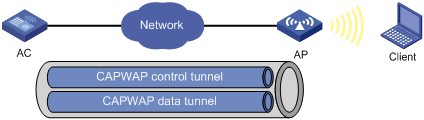
AC discovery
After starting up with zero configurations, an AP automatically creates VLAN-interface 1 and enables the DHCP client, DHCPv6 client, and DNS features on the interface. Then it obtains its own IP address from the DHCP server and discovers ACs by using the following methods in descending order:
· Static IP address:
If AC IP addresses have been manually configured for the AP, the AP sends a unicast discovery request to each AC IP address to discover ACs.
· DHCP options:
a. The AP obtains AC IPv4 addresses from Option 138 or Option 43 or AC IPv6 addresses from Option 52 that are sent from the DHCP server.
If the AP obtains IPv4 addresses of ACs from both Option 138 and Option 43, the AP uses the addresses in Option 138.
b. The AP sends a unicast discovery request to each received AC address to discover ACs.
For more information about DHCP options, see "DHCP" and "DNS."
· DNS:
a. The AP obtains the domain name suffix from the DHCP server.
b. The AP adds the suffix to the host name.
c. The DNS server translates the domain name into IP addresses.
d. The AP sends a unicast discovery request to each IP address to discover ACs.
For more information about DNS, see Layer 3—IP Services Configuration Guide.
· Broadcast:
The AP broadcasts discovery requests to IP address 255.255.255.255 to discover ACs.
· IPv4 multicast:
The AP sends multicast discovery requests to IPv4 address 224.0.1.140 to discover ACs.
· IPv6 multicast:
The AP sends multicast discovery requests to IPv6 address FF0E::18C to discover ACs.
The AP does not stop AC discovery until it establishes a CAPWAP tunnel with one of the discovered ACs.
CAPWAP tunnel establishment
Figure 14 Establishing a CAPWAP tunnel
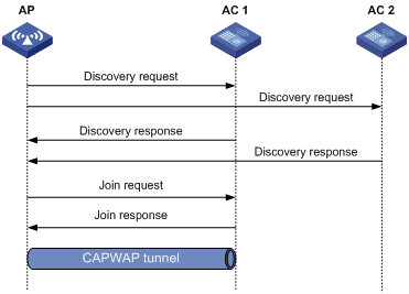
As shown in Figure 14, the AP and an AC establish a CAPWAP tunnel by using the following process:
1. The AP sends a discovery request to each AC to discover ACs.
2. After receiving a discovery request, each AC determines whether to send a discovery response based on its local configuration and the information in the request. A discovery response contains the following information:
¡ Whether the AC saves information about the AP.
¡ AP connection priority.
¡ Load information.
3. After receiving discovery responses, the AP compares information in the responses and selects the optimal AC.
4. The AP sends a join request to the AC.
5. After receiving the join request, the AC examines information in the request to determine whether to provide access services to the AP and sends a join response.
6. After receiving the join response, the AP examines the result code in the response:
¡ If the result code represents failure, the AP does not establish a CAPWAP tunnel with the AC.
¡ If the result code represents success, the AP establishes a CAPWAP tunnel with the AC.
AP groups
AP groups enable you to configure multiple APs in a batch to reduce configuration workload.
APs in an AP group use the configuration of the group. By default, all APs belong to the system-defined AP group default-group. The system-defined AP group cannot be created or deleted.
You can configure AP grouping rules by AP names, serial IDs, MAC addresses, and IP addresses to add APs to the specified AP group. Priorities of these grouping rules are in descending order. If an AP does not match any grouping rules, it is added to the system-defined AP group.
When you configure an AP group, follow these restrictions and guidelines:
· An AP can be added to only one AP group.
· You cannot delete an AP group that contains an AP.
· You cannot create grouping rules for the system-defined AP group.
· You cannot create the same grouping rule for different AP groups. If you do so, the most recent configuration takes effect.
An AP selects AP settings in the following order:
1. Settings configured exclusively for the AP.
2. Settings configured for the AP group where the AP belongs.
3. Global settings.
4. Default settings for global configuration.
Global configuration
Global configuration takes effect on APs in all AP groups.
AP preprovisioning
AP preprovisioning allows you to configure network settings for APs on an AC. The AC automatically assigns these settings to the APs in run state through CAPWAP tunnels in a batch. This reduces the work load in large WLAN networks.
You must save these settings in the preprovisioned configuration file wlan_ap_prvs.xml for the APs. These settings take effect after the APs restart.
This feature takes effect only on master ACs.
You can configure network settings in AP provision configuration or AP group provision configuration. Settings in AP provision configuration have a higher priority.
Preprovisioned settings include the following items:
· Host name of the AC with which the AP establishes a CAPWAP tunnel.
· AP IP address.
· AP gateway address.
· DNS domain name suffix that is used during AC discovery.
· DNS server IP address that is used during AC discovery.
· 802.1X client settings.
Region code
A region code determines characteristics such as available frequencies, available channels, and transmit power level. Set a valid region code before configuring an AP.
To prevent regulation violation caused by region code modification, lock the region code.
Auto AP
The auto AP feature enables APs to connect to an AC without manual AP configuration. The AC names auto APs by their MAC addresses. This feature simplifies configuration when you deploy a large number of APs in a WLAN.
During AC discovery, an AP first connects to an AC that saves information about the AP. If no AC has information about the AP, the AP selects the optimal AC with auto AP enabled to establish a CAPWAP tunnel.
To configure an auto AP, you must use auto AP persistence to convert the auto AP to a manual AP or configure it through an AP group.
For security purposes, use the auto AP feature in conjunction with the auto AP persistence feature. Disable the auto AP feature after all auto APs connect to the AC for the first time. Auto APs are converted to manual APs the first time they are connected to the AC.
AC backup
AC backup enables an AP to establish a CAPWAP tunnel with both the master AC and the backup AC in a VSRP group. In the VSRP group, the AC that is assigned a higher AP connection priority is the master AC. The AC whose IP address is configured on the master AC is the backup AC. The master AC synchronizes AP and client information to the backup in real time. When the master AC fails, the backup AC takes over to avoid service interruption.
Configuration prerequisites
Before you manage APs, complete the following tasks:
· Create a DHCP address pool on the DHCP server to assign IP addresses to APs.
· If DHCP options are used for AC discovery, perform either of the following tasks for the specified DHCP address pool on the DHCP server:
¡ Configure Option 138 or Option 43 to specify AC IPv4 address.
¡ Configure Option 52 to specify AC IPv6 address.
· If DNS is used for AC discovery, configure the IP address of the DNS server and the AC domain name suffix in the specified DHCP address pool on the DHCP server. Then configure the mapping between the domain name and the AC IP address on the DNS server.
· Make sure the APs and the AC can reach each other.
For more information about DHCP and DNS configuration, see "DHCP" and "DNS."
Client rate limiting features
Client rate limiting prevents aggressive use of bandwidth by one client and ensures fair use of bandwidth among clients associated with the same AP.
Client rate limit mode
The following modes are available for client rate limiting:
· Dynamic mode—Sets the total bandwidth shared by all clients. The rate limit for each client is the total rate divided by the number of online clients. For example, if the total rate is 10 Mbps and five clients are online, the rate limit for each client is 2 Mbps.
· Static mode—Sets the bandwidth that can be used by each client. When the rate limit multiplied by the number of associated clients exceeds the available bandwidth provided by the AP, the clients might not get the set bandwidth.
You can configure the client rate limit mode only for service-based and radio-based client rate limiting.
Client rate limit methods
You can use the following methods to limit the traffic rate:
· Client-type-based client rate limiting—The setting takes effect on all clients. Traffic rate of each client type cannot exceed the corresponding setting.
· Service-based client rate limiting—The setting takes effect on all clients associated with the same wireless service.
· Radio-based client rate limiting—The setting takes effects on all clients associated with the same radio.
If more than one method and mode are configured, all settings take effect. The rate for a client will be limited to the minimum value among all the client rate limiting settings.
Bandwidth guaranteeing features
Bandwidth guaranteeing provides the following functions:
· Ensures that traffic from all BSSs can pass through freely when the network is not congested.
· Ensures that each BSS can get the guaranteed bandwidth when the network is congested.
This feature improves bandwidth efficiency and maintains fair use of bandwidth among WLAN services. For example, you assign SSID1, SSID2, and SSID3 25%, 25%, and 50% of the total bandwidth. When the network is not congested, SSID1 can use all idle bandwidth in addition to its guaranteed bandwidth. When the network is congested, SSID1 is guaranteed with 25% of the bandwidth.
This feature applies only to AP-to-client traffic.
WMM features
An 802.11 network provides contention-based wireless access. To provide applications with QoS services, IEEE developed 802.11e for 802.11-based WLANs.
While IEEE 802.11e was being standardized, Wi-Fi Alliance defined the Wi-Fi Multimedia (WMM) standard to allow QoS provision devices of different vendors to interoperate. WMM enables a WLAN to provide QoS services, so that audio and video applications can have better performance in WLANs.
WMM status
You can view the WMM enabling status for each AP that is connected to the AC.
WMM settings
You can configure the maximum number of SVP mappings, CAC policies, and allowed clients.
SVP mapping assigns packets that have the protocol ID 119 in the IP header to the AC-VI or AC-VO queue to provide SVP packets with the specified priority. When SVP mapping is disabled, SVP packets are assigned to the AC-BE queue.
Connect Admission Control (CAC) limits the number of clients that can use high-priority ACs (AC-VO and AC-VI) to make sure there is enough bandwidth for these clients. If a high-priority AC (AC-VO or AC-VI) is required, a client must send a request to the AP. The AP returns a positive or negative response based on the channel-usage-based admission policy or client-based admission policy. If the request is rejected, the AP assigns AC-BE to clients.
EDCA parameters and ACK policies
You can view and modify the EDCA parameters and ACK policies.
EDCA is a channel contention mechanism defined by WMM to preferentially transmit packets with high priority and allocate more bandwidth to such packets.
WMM defines the following EDCA parameters:
· Arbitration inter-frame spacing number—In 802.11-based WLAN, each client has the same idle duration (DIFS), but WMM defines an idle duration for each AC. The idle duration increases as the AIFSN increases.
· Exponent form of CWmin/Exponent form of CWmax—ECWmin/ECWmax determines the backoff slots, which increase as the two values increase.
· Transmission opportunity limit—TXOP limit specifies the maximum time that a client can hold the channel after a successful contention. A larger value represents a longer time. If the value is 0, a client can send only one packet each time it holds the channel.
WMM defines the following ACK policies:
· Normal ACK—The recipient acknowledges each received unicast packet.
· No ACK—The recipient does not acknowledge received packets during wireless packet exchange. This policy improves the transmission efficiency in an environment where communication quality is strong and interference is weak. If communication quality deteriorates, this policy might increase the packet loss rate.
EDCA parameters of AC queues for clients
You can view and modify EDCA parameters, and enable or disable a CAC policy.
Client WMM statistics
You can view the following information:
· The device's basic information such as SSID.
· Data traffic statistics.
· APSD attribute for an AC queue.
U-APSD is a power saving method defined by WMM to save client power. U-APSD enables clients in sleep mode to wake up and receive the specified number of packets only after receiving a trigger packet. U-APSD improves the 802.11 APSD power saving mechanism.
U-APSD is automatically enabled after you enable WMM.
Traffic statistics
You can view the following information:
· User priority for packets from wired networks.
· Traffic Identifier.
· Traffic direction.
· Surplus bandwidth allowance.
WIPS
Wireless Intrusion Prevention System (WIPS) helps you monitor your WLAN, detect attacks and rogue devices, and take countermeasures. WIPS provides a complete solution for WLAN security.
WIPS contains the network management module, the AC, and sensors (APs enabled with WIPS). They provide the following functions:
· The sensors monitor the WLAN, collect channel information, and report the information to the AC for further analysis.
· The AC determines attacks and rogue devices, takes countermeasures, and triggers alarms.
· The network management module allows you to configure WIPS in the Web interface. It provides configuration management, report generation, and alarm management functions.
Enabling WIPS
Before enabling WIPS for a radio of an AP, you must add the AP to a virtual security domain (VSD).
Configuring a VSD
You can apply a classification policy, attack detection policy, signature policy, or countermeasure policy to a VSD to enable the policy to take effect on the radios in the VSD.
Configuring device classification
Classification policy
You can enable WIPS to classify devices by using either of the following methods:
· Automatic classification—WIPS automatically classifies devices by adding the MAC addresses, OUIs, or SSIDs of the devices to the specified lists. WIPS also allows you to classify APs by using user-defined AP classification rules.
· Manual classification—You manually specify a category for a device. Manual classification is applicable only to APs.
If you configure both automatic classification and manual classification, manual classification takes effect.
AP classification
As shown in Table 23, WIPS classifies detected APs according to the predefined classification rules.
|
Category |
Description |
Classification rule |
|
Authorized AP |
An AP that is permitted in the WLAN. |
· Not in the prohibited device list. · Has been connected to the AC. · Configured as an authorized AP. |
|
Rogue AP |
An AP that cannot be used in the WLAN. |
· In the prohibited device list. · Not in the OUI configuration file. · Configured as a rogue AP. |
|
Misconfigured AP |
An AP that can be used in the WLAN but has incorrect configuration. |
· In the permitted device list but with an incorrect SSID. · Not in the prohibited device list but in the OUI configuration file. · In the trusted OUI list or permitted device list but not connected to the AC. |
|
External AP |
An AP that is in an adjacent WLAN. |
N/A |
|
Ad hoc |
An AP operating in Ad hoc mode. WIPS detects Ad hoc APs by listening to beacon frames. |
N/A |
|
Potential-authorized AP |
An AP that is possibly authorized. |
Not in any of the following lists: · Permitted device list. · Prohibited device list. · Trusted OUI list. |
|
Potential-rogue AP |
An AP that is possibly a rogue AP. |
Has incorrect wireless configuration and is not in any of the following lists: · Permitted device list. · Prohibited device list. · Trusted OUI list. If the wired port on an AP has been connected to the network, the AP is a rogue AP. |
|
Potential-external AP |
An AP that is possibly an external AP. |
· Has incorrect wireless service configuration. · The wired port has not been connected to the network. · Not in any of the following lists: ¡ Permitted device list. ¡ Prohibited device list. ¡ Trusted OUI list. |
|
Uncategorized AP |
An AP whose category cannot be determined. |
N/A |
WIPS classifies detected APs by following the procedure shown in Figure 15.
Figure 15 AP classification flow
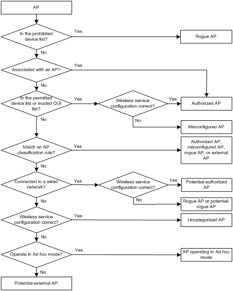
Client classification
As shown in Table 24, WIPS classifies detected clients according to the predefined classification rules.
Table 24 Client classification
|
Category |
Description |
Classification rule |
|
Authorized client |
A client that is permitted in the WLAN. |
· In the permitted device list and associated with an authorized AP. · Has passed authentication and is associated with an authorized AP. |
|
Unauthorized client |
A client that cannot be used in the WLAN. |
· In the prohibited device list. · Associated with a rogue AP. · Not in the OUI configuration file. |
|
Misassociated client |
A client that is associated with an unauthorized AP. |
In the permitted device list but associated with an unauthorized AP. A misassociated client might bring security threats to the network. |
|
Uncategorized client |
A client whose category cannot be determined. |
N/A |
WIPS classifies detected clients by following the procedure shown in Figure 16.
Figure 16 Client classification flow
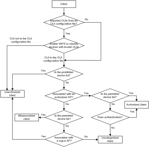
Configuring attack detection
WIPS detects attacks by listening to 802.11 frames and triggers alarms to notify the administrator.
Device entry attack detection
Attackers can send invalid packets to WIPS to increase processing costs. WIPS periodically examines the learned device entries to determine whether to rate limit device entry learning. If the number of AP or client entries learned within the specified interval exceeds the threshold, WIPS triggers an alarm and stops learning new entries.
Flood attack detection
An AP might be facing a flood attack if it receives a large number of same-type frames within a short period of time. To prevent the AP from being overwhelmed, WIPS periodically examines incoming packet statistics, and alarms when it detects a suspicious flood attack. WIPS can detect the following flood attacks:
· Probe request/association request/reassociation request flood attack—Floods the association table of an AP by imitating many clients sending probe requests/association requests/reassociation requests to the AP.
· Authentication request flood attack—Floods the association table of an AP by imitating many clients sending authentication requests to the AP.
· Beacon flood attack—Floods beacon frames imitating a large number of fake APs to interrupt client association.
· Block Ack flood attack—Floods Block Ack frames to the AP to interrupt the operation of the Block Ack mechanism.
· RTS/CTS flood attack—Floods RTS/CTS frames to reserve the RF medium and force other wireless devices sharing the RF medium to hold back their transmissions. This attack takes advantage of vulnerabilities of the virtual carrier mechanism.
· Broadcast/unicast deauthentication flood attack—Spoofs deauthentication frames from the AP to the associated clients to disassociate the clients from the AP. This attack can rapidly terminate wireless services to multiple clients.
· Broadcast/unicast disassociation flood attack—Spoofs disassociation frames from the AP to the associated clients to disassociate the clients from the AP. This attack can rapidly terminate wireless services to multiple clients.
· EAPOL-start flood attack—Exhausts the AP's resources by imitating many clients sending EAPOL-start frames defined in IEEE 802.1X to the AP.
· Null data flood attack—Spoofs null data frames from a client to the AP. The AP determines that the client is in power save mode and buffers frames for the client. When the aging time of the buffered frames expires, the AP discards the frames. This interrupts the client's communication with the AP.
· EAPOL-logoff flood attack—The IEEE 802.1X standard defines the authentication protocol using Extensible Authentication Protocol over LANs (EAPOL). A client needs to send an EAPOL-logoff frame to terminate the session with an AP. The EAPOL-logoff frames are not authenticated, and an attacker can spoof EAPOL-logoff frames to disassociate a client.
· EAP-success/failure flood attack—In a WLAN using 802.1X authentication, an AP sends an EAP-success or EAP-failure frame to a client to inform authentication success or failure. An attacker can spoof the MAC address of an AP to send EAP-success or EAP-failure frames to a client to disrupt the authentication process.
Malformed packet detection
WIPS determines that a frame is malformed if the frame matches the criteria shown in Table 25, and then it triggers alarms and logs. WIPS can detect 16 kinds of malformed packets.
Table 25 Malformed frame match criteria
|
Detection type |
Applicable frames |
Match criteria |
|
Duplicate IE detection |
All management frames |
Duplicate IE. This type of detection is not applicable to vendor-defined IEs. |
|
FATA-Jack detection |
Authentication frames |
The value of the authentication algorithm number is 2. |
|
Abnormal IBSS and ESS setting detection |
· Beacon frames · Probe response frames |
Both IBSS and ESS are set to 1. |
|
Invalid source address detection |
All management frames |
· The TO DS is 1, indicating that the frame is sent to the AP by a client. · The source MAC address of the frame is a multicast or broadcast address. |
|
Malformed association request frame detection |
Association request frames |
The frame length is 0. |
|
Malformed authentication request frame detection |
Authentication request frames |
· The authentication algorithm number does not conform to the 802.11 protocol and is larger than 3. · The authentication transaction sequence number is 1 and the status code is not 0. · The authentication transaction sequence number is larger than 4. |
|
Invalid deauthentication code detection |
Deauthentication frames |
The reason code is 0 or is in the range of 67 to 65535. |
|
Invalid disassociation code detection |
Disassociation frames |
The reason code is 0 or is in the range of 67 to 65535. |
|
Malformed HT IE detection |
· Beacon frames · Probe responses · Association responses · Reassociation requests |
· The SM power save value for the HT capabilities IE is 2. · The secondary channel offset value for the HT operation IE is 2. |
|
Invalid IE length detection |
All management frames |
The IE length does not conform to the 802.11 protocol. |
|
Invalid packet length detection |
All management frames |
The remaining length of the IE is not zero after the packet payload is resolved. |
|
Malformed probe response frame detection |
Probe response frames |
The frame is not a mesh frame and its SSID length is 0. |
|
Oversized EAPOL key detection |
EAPOL-Key frames |
The TO DS is 1 and the length of the key is larger than 0. |
|
Oversized SSID detection |
· Beacon frames · Probe requests · Probe responses · Association request frames |
The SSID length is larger than 32. |
|
Redundant IE detection |
All management frames |
The IE is not a necessary IE to the frame and is not a reserved IE. |
|
Oversized duration detection |
· Unicast management frames · Unicast data frames · RTS, CTS, and ACK frames |
The packet duration value is larger than the specified threshold. |
Attack detection
· Spoofing attack detection
In a spoofing attack, the attacker sends frames on behalf of another device to threaten the network. WIPS supports detection of the following spoofing attacks:
¡ Frame spoofing—A fake AP spoofs an authorized AP to send beacon or probe response frames to induce clients to associate with it.
¡ AP MAC address spoofing—A client spoofs an authorized AP to send deauthentication or disassociation frames to other clients. This can cause the clients to go offline and affect the correct operation of the WLAN.
¡ Client MAC address spoofing—A fake AP spoofs an authorized client to associate with an authorized AP.
When the RC4 encryption algorithm, used by the WEP security protocol, uses an insecure IV, the WEP key is more likely to be cracked. Such an insecure IV is called a weak IV. WIPS prevents this kind of attack by detecting the IV in each WEP packet.
· Windows bridge detection
When a wireless client connected to a wired network establishes a Windows bridge through the wired NIC, the client can bridge an external AP with the internal network. This might bring security problems to the internal network. WIPS detects Windows bridges by analyzing data frames sent by associated clients.
· Detection on clients with the 40 MHz bandwidth mode disabled
802.11n devices support both the 20 MHz and 40 MHz bandwidth modes. If the 40 MHz bandwidth mode is disabled on a client, other clients associated with the same AP as the client must also use the 20 MHz bandwidth. This affects network throughput and efficiency.
WIPS detects such clients by detecting probe request frames sent by the clients.
Omerta is a DoS attack tool based on the 802.11 protocol. It sends disassociation frames with the reason code 0x01 to disassociate clients. Reason code 0x01 indicates an unknown disassociation reason. WIPS detects Omerta attacks by detecting the reason code of each disassociation frame.
· Unencrypted device detection
An authorized AP or client that is transmitting unencrypted frames might bring security problems to the network. WIPS detects unencrypted devices by analyzing the frames sent the by authorized APs or clients.
An attacker sets up a rogue AP with the same SSID as a hotspot to lure the clients to associate with it. After the clients associate with the malicious AP, the attacker initiates further attacks to obtain client information.
You can configure a hotspot file to enable WIPS to detect hotspot attacks.
An AP operating in HT-greenfield mode might cause collisions, errors, and retransmissions because it cannot communicate with 802.11a/b/g devices. WIPS detects HT-greenfield APs by analyzing the beacon frames or probe response frames sent by APs.
· Association/reassociation DoS attack detection
An association/reassociation DoS attack floods the association table of an AP by imitating many clients sending association requests to the AP. When the number of entries in the table reaches the upper limit, the AP cannot process requests from legitimate clients.
In an MITM attack, the attacker sets up a rogue AP and lures a client to associate with it. Then the rogue AP spoofs the MAC address of the client to associate with the authorized AP. When the client and the authorized AP communicate, the rogue AP captures packets from both the client and the authorized AP. The rogue AP might modify the frames and obtain the frame information. WIPS detects MITM attacks by detecting clients that are disassociated from an authorized AP and associated with a honeypot AP.
An attacker might intrude on the internal networks through a wireless bridge. When detecting a wireless bridge, WIPS generates an alarm. If the wireless bridge is in a mesh network, WIPS records the mesh link.
· AP channel change detection
WIPS detects the channel change events for APs in the WLAN.
· Broadcast disassociation/deauthentication attack detection
An attacker spoofs a legitimate AP to send a broadcast disassociation or deauthentication frame to log off all clients associated with the AP.
· AP impersonation attack detection
In an AP impersonation attack, a malicious AP that has the same BSSID and ESSID as a legitimate AP lures the clients to associate with it. Then this impersonating AP initiates hotspot attacks or fools the detection system.
WIPS detects AP impersonation attacks by detecting the interval at which an AP sends beacon frames.
WIPS detects the number of APs in the WLAN and triggers an alarm for an AP flood attack when the number of APs exceeds the specified threshold.
In a honeypot AP attack, the attacker sets up a malicious AP to lure clients to associate with it. The SSID of the malicious AP is similar to the SSID of a legitimate AP. After a client associates with a honeypot AP, the honeypot AP initiates further attacks such as port scanning or fake authentication to obtain client information.
WIPS detects honeypot APs by detecting SSIDs of external APs. If the similarity between the SSID of an external AP and the SSID of a legitimate AP reaches the specified threshold, WIPS generates an alarm.
An attacker spoofs the MAC address of a client to send power save on frames to an AP. The AP caches the frames for the client. The attacked client cannot receive data frames because the AP determines that the client is still in power save mode. When the aging time of the cached frames expires, the AP discards the frames. WIPS detects power save attacks by determining the ratio of power save on frames to power save off frames.
A soft AP refers to a client that acts as an AP and provides wireless services. An attacker can access the internal network through a soft AP and then initiate further attacks. WIPS detects soft APs by detecting the interval at which a device switches its roles between client and AP.
· Prohibited channel detection
After you configure a permitted channel list and enable prohibited channel detection, WIPS determines that channels that are not in the permitted channel list are prohibited channels.
User-defined attack detection based on signatures
WIPS provides user-defined attack detection based on signatures. A signature contains a packet identification method and actions to take on the matching packets. The sensor matches the detected packets against the signature, and takes actions defined in the signature if a packet matches the signature.
A signature can contain a maximum of six subsignatures, which can be defined based on the frame type, MAC address, serial ID, SSID length, SSID, and frame pattern. A packet matches a signature only when it matches all the subsignatures in the signature.
Countermeasures
Rogue devices are susceptible to attacks and might bring security problems to the WLAN. WIPS enables you to take countermeasures against rogue devices.
Configuring the alarm-ignored device list
For wireless devices in an alarm-ignored device list, WIPS only monitors them but does not trigger any alarms.
Whitelist and blacklist features
· Whitelist—Contains the MAC addresses of all clients allowed to access the WLAN. Frames from clients not in the whitelist are discarded. This list is manually configured.
· Static blacklist—Contains the MAC addresses of clients forbidden to access the WLAN. This list is manually configured.
· Dynamic blacklist—Contains the MAC addresses of clients forbidden to access the WLAN through specific APs within the specified aging time. A client is dynamically added to the list if an AP determines this client is a rogue client.
When an AP receives an association request and sends an add mobile message to the AC, the AC performs the following operations to determine whether to permit the client:
1. Searches the whitelist.
¡ If the client MAC address does not match any entries in the whitelist, the client is rejected.
¡ If there is a match, the client is permitted.
2. Searches the static and dynamic blacklists if no whitelist entries exist.
¡ If the client MAC address matches an entry in either blacklist, the client is rejected.
¡ If there is no match, or no blacklist entries exist, the client is permitted.
The static blacklist and whitelist configured on the AC apply to all APs connected to the AC, and the dynamic blacklist applies to APs that received attack packets.
Radio management
Radio frequency (RF) is a rate of electrical oscillation in the range of 300 kHz to 300 GHz. WLAN uses the 2.4 GHz band and 5 GHz band radio frequencies as the transmission media. The 2.4 GHz band includes radio frequencies from 2.4 GHz to 2.4835GHz. The 5 GHz band includes radio frequencies from 5.150 GHz to 5.350 GHz and from 5.725 GHz to 5.850 GHz.
The term "radio frequency" or its abbreviation RF is also used as a synonym for "radio" in wireless communication.
Radio mode
IEEE defines the 802.11a, 802.11b, 802.11g, 802.11n, and 802.11ac radio modes. Table 26 provides a comparison of these radio modes.
Table 26 Comparison of 802.11 standards
|
IEEE standard |
Frequency band |
Maximum rate |
Indoor coverage |
Outdoor coverage |
|
802.11a |
5 GHz |
54 Mbps |
About 50 meters (164.04 ft) |
About 100 meters (328.08 ft) |
|
802.11b |
2.4 GHz |
11 Mbps |
About 300 meters (984.3 ft) |
About 600 meters (1968.50 ft) |
|
802.11g |
2.4 GHz |
54 Mbps |
About 300 meters (984.3 ft) |
About 600 meters (1968.50 ft) |
|
802.11n |
2.4 GHz or 5 GHz |
600 Mbps |
About 300 meters (984.3 ft) |
About 600 meters (1968.50 ft) |
|
802.11ac |
5 GHz |
6900 Mbps |
About 30 meters (98.43 ft) |
About 60 meters (196.85 ft) |
|
|
NOTE: 802.11g, 802.11n, and 802.11ac are backward compatible. |
Channel
A channel is a range of frequencies with a specific bandwidth.
The 2.4 GHz band has 14 channels. The bandwidth for each channel is 20 MHz and each two channels are spaced 5 MHz apart. Among the 14 channels, four groups of non-overlapping channels exist and the most commonly used one contains channels 1, 6, and 11.
The 5 GHz band can provide higher rates and is more immune to interference. There are 24 non-overlapping channels designated to the 5 GHz band. The channels are spaced 20 MHz apart with a bandwidth of 20 MHz. The available channels vary by country.
Transmit power
Transmit power reflects the signal strength of a wireless device. A higher transmit power enables a radio to cover a larger area but it brings more interference to adjacent devices. The signal strength decreases as the transmission distance increases.
Transmission rate
Transmission rate refers to the speed at which wireless devices transmit traffic. It varies by radio mode and spreading, coding, and modulation schemes. The following are rates supported by different types of radios:
· 802.11a—6 Mbps, 9 Mbps, 12 Mbps, 18 Mbps, 24 Mbps, 36 Mbps, 48 Mbps, and 54 Mbps.
· 802.11b—1 Mbps, 2 Mbps, 5.5 Mbps, and 11 Mbps.
· 802.11g—1 Mbps, 2 Mbps, 5.5 Mbps, 6 Mbps, 9 Mbps, 11 Mbps, 12 Mbps, 18 Mbps, 24 Mbps, 36 Mbps, 48 Mbps, and 54 Mbps.
· 802.11n—Rates for 802.11n radios vary by channel bandwidth. For more information, see "MCS."
· 802.11ac—Rates for 802.11ac radios vary by channel bandwidth and number of spatial streams (NSS). For more information, see "VHT-MCS."
MCS
Modulation and Coding Scheme (MCS) defined in IEEE 802.11n-2009 determines the modulation, coding, and number of spatial streams. An MCS is identified by an MCS index, which is represented by an integer in the range of 0 to 76. An MCS index is the mapping from MCS to a data rate.
Table 27 and Table 28 show sample MCS parameters for 20 MHz and 40 MHz.
When the bandwidth mode is 20 MHz, MCS indexes 0 through 15 are mandatory for APs, and MCS indexes 0 through 7 are mandatory for clients.
Table 27 MCS parameters for 20 MHz
|
MCS index |
Number of spatial streams |
Modulation |
Data rate (Mbps) |
|
|
800ns GI |
400ns GI |
|||
|
0 |
1 |
BPSK |
6.5 |
7.2 |
|
1 |
1 |
QPSK |
13.0 |
14.4 |
|
2 |
1 |
QPSK |
19.5 |
21.7 |
|
3 |
1 |
16-QAM |
26.0 |
28.9 |
|
4 |
1 |
16-QAM |
39.0 |
43.3 |
|
5 |
1 |
64-QAM |
52.0 |
57.8 |
|
6 |
1 |
64-QAM |
58.5 |
65.0 |
|
7 |
1 |
64-QAM |
65.0 |
72.2 |
|
8 |
2 |
BPSK |
13.0 |
14.4 |
|
9 |
2 |
QPSK |
26.0 |
28.9 |
|
10 |
2 |
QPSK |
39.0 |
43.3 |
|
11 |
2 |
16-QAM |
52.0 |
57.8 |
|
12 |
2 |
16-QAM |
78.0 |
86.7 |
|
13 |
2 |
64-QAM |
104.0 |
115.6 |
|
14 |
2 |
64-QAM |
117.0 |
130.0 |
|
15 |
2 |
64-QAM |
130.0 |
144.4 |
Table 28 MCS parameters for 40 MHz
|
MCS index |
Number of spatial streams |
Modulation |
Data rate (Mbps) |
|
|
800ns GI |
400ns GI |
|||
|
0 |
1 |
BPSK |
13.5 |
15.0 |
|
1 |
1 |
QPSK |
27.0 |
30.0 |
|
2 |
1 |
QPSK |
40.5 |
45.0 |
|
3 |
1 |
16-QAM |
54.0 |
60.0 |
|
4 |
1 |
16-QAM |
81.0 |
90.0 |
|
5 |
1 |
64-QAM |
108.0 |
120.0 |
|
6 |
1 |
64-QAM |
121.5 |
135.0 |
|
7 |
1 |
64-QAM |
135.0 |
150.0 |
|
8 |
2 |
BPSK |
27.0 |
30.0 |
|
9 |
2 |
QPSK |
54.0 |
60.0 |
|
10 |
2 |
QPSK |
81.0 |
90.0 |
|
11 |
2 |
16-QAM |
108.0 |
120.0 |
|
12 |
2 |
16-QAM |
162.0 |
180.0 |
|
13 |
2 |
64-QAM |
216.0 |
240.0 |
|
14 |
2 |
64-QAM |
243.0 |
270.0 |
|
15 |
2 |
64-QAM |
270.0 |
300.0 |
MCS indexes are classified into the following types:
· Mandatory MCS indexes—Mandatory MCS indexes for an AP. To associate with an 802.11n AP, a client must support the mandatory MCS indexes for the AP.
· Supported MCS indexes—MCS indexes supported by an AP except for the mandatory MCS indexes. If a client supports both mandatory and supported MCS indexes, the client can use a supported rate to communicate with the AP.
· Multicast MCS index—MCS index for the rate at which an AP transmits multicast frames.
|
|
NOTE: For all the MCS data rate tables, see IEEE 802.11n-2009. |
VHT-MCS
802.11 ac uses Very High Throughput Modulation and Coding Scheme (VHT-MCS) indexes to indicate wireless data rates. A VHT-MCS is identified by a VHT-MCS index, which is represented by an integer in the range of 0 to 9. A VHT-MCS index is the mapping from VHT-MCS to a data rate.
802.11ac supports the 20 MHz, 40 MHz, 80 MHz, and 160 MHz bandwidth modes, and supports a maximum of eight spatial streams.
Table 29 through Table 40 show VHT-MCS parameters that are supported by an AP.
Table 29 VHT-MCS parameters (20 MHz, NSS=1)
|
VHT-MCS index |
Modulation |
Data rate (Mbps) |
|
|
800ns GI |
400ns GI |
||
|
0 |
BPSK |
6.5 |
7.2 |
|
1 |
QPSK |
13.0 |
14.4 |
|
2 |
QPSK |
19.5 |
21.7 |
|
3 |
16-QAM |
26.0 |
28.9 |
|
4 |
16-QAM |
39.0 |
43.3 |
|
5 |
64-QAM |
52.0 |
57.8 |
|
6 |
64-QAM |
58.5 |
65.0 |
|
7 |
64-QAM |
65.0 |
72.2 |
|
8 |
256-QAM |
78.0 |
86.7 |
|
9 |
Not valid |
||
Table 30 VHT-MCS parameters (20 MHz, NSS=2)
|
VHT-MCS index |
Modulation |
Data rate (Mbps) |
|
|
800ns GI |
400ns GI |
||
|
0 |
BPSK |
13.0 |
14.4 |
|
1 |
QPSK |
26.0 |
28.9 |
|
2 |
QPSK |
39.0 |
43.3 |
|
3 |
16-QAM |
52.0 |
57.8 |
|
4 |
16-QAM |
78.0 |
86.7 |
|
5 |
64-QAM |
104.0 |
115.6 |
|
6 |
64-QAM |
117.0 |
130.0 |
|
7 |
64-QAM |
130.0 |
144.4 |
|
8 |
256-QAM |
156.0 |
173.3 |
|
9 |
Not valid |
||
Table 31 VHT-MCS parameters (20 MHz, NSS=3)
|
VHT-MCS index |
Modulation |
Data rate (Mbps) |
|
|
800ns GI |
400ns GI |
||
|
0 |
BPSK |
19.5 |
21.7 |
|
1 |
QPSK |
39.0 |
43.3 |
|
2 |
QPSK |
58.5 |
65.0 |
|
3 |
16-QAM |
78.0 |
86.7 |
|
4 |
16-QAM |
117.0 |
130.0 |
|
5 |
64-QAM |
156.0 |
173.3 |
|
6 |
64-QAM |
175.5 |
195.0 |
|
7 |
64-QAM |
195.0 |
216.7 |
|
8 |
256-QAM |
234.0 |
260.0 |
|
9 |
256-QAM |
260.0 |
288.9 |
Table 32 VHT-MCS parameters (20 MHz, NSS=4)
|
VHT-MCS index |
Modulation |
Data rate (Mbps) |
|
|
800ns GI |
400ns GI |
||
|
0 |
BPSK |
26.0 |
28.9 |
|
1 |
QPSK |
52.0 |
57.8 |
|
2 |
QPSK |
78.0 |
86.7 |
|
3 |
16-QAM |
104.0 |
115.6 |
|
4 |
16-QAM |
156.0 |
173.3 |
|
5 |
64-QAM |
208.0 |
231.1 |
|
6 |
64-QAM |
234.0 |
260.0 |
|
7 |
64-QAM |
260.0 |
288.9 |
|
8 |
256-QAM |
312.0 |
346.7 |
|
9 |
Not valid |
||
Table 33 VHT-MCS parameters (40 MHz, NSS=1)
|
VHT-MCS index |
Modulation |
Data rate (Mbps) |
|
|
800ns GI |
400ns GI |
||
|
0 |
BPSK |
13.5 |
15.0 |
|
1 |
QPSK |
27.0 |
30.0 |
|
2 |
QPSK |
40.5 |
45.0 |
|
3 |
16-QAM |
54.0 |
60.0 |
|
4 |
16-QAM |
81.0 |
90.0 |
|
5 |
64-QAM |
108.0 |
120.0 |
|
6 |
64-QAM |
121.5 |
135.0 |
|
7 |
64-QAM |
135.0 |
150.0 |
|
8 |
256-QAM |
162.0 |
180.0 |
|
9 |
256-QAM |
180.0 |
200.0 |
Table 34 VHT-MCS parameters (40 MHz, NSS=2)
|
VHT-MCS index |
Modulation |
Data rate (Mbps) |
|
|
800ns GI |
400ns GI |
||
|
0 |
BPSK |
27.0 |
30.0 |
|
1 |
QPSK |
54.0 |
60.0 |
|
2 |
QPSK |
81.0 |
90.0 |
|
3 |
16-QAM |
108.0 |
120.0 |
|
4 |
16-QAM |
162.0 |
180.0 |
|
5 |
64-QAM |
216.0 |
240.0 |
|
6 |
64-QAM |
243.0 |
270.0 |
|
7 |
64-QAM |
270.0 |
300.0 |
|
8 |
256-QAM |
324.0 |
360.0 |
|
9 |
256-QAM |
360.0 |
400.0 |
Table 35 VHT-MCS parameters (40 MHz, NSS=3)
|
VHT-MCS index |
Modulation |
Data rate (Mbps) |
|
|
800ns GI |
400ns GI |
||
|
0 |
BPSK |
40.5 |
45.0 |
|
1 |
QPSK |
81.0 |
90.0 |
|
2 |
QPSK |
121.5 |
135.0 |
|
3 |
16-QAM |
162.0 |
180.0 |
|
4 |
16-QAM |
243.0 |
270.0 |
|
5 |
64-QAM |
324.0 |
360.0 |
|
6 |
64-QAM |
364.5 |
405.0 |
|
7 |
64-QAM |
405.0 |
450.0 |
|
8 |
256-QAM |
486.0 |
540.0 |
|
9 |
256-QAM |
540.0 |
600.0 |
Table 36 VHT-MCS parameters(40 MHz, NSS=4)
|
VHT-MCS index |
Modulation |
Data rate (Mbps) |
|
|
800ns GI |
400ns GI |
||
|
0 |
BPSK |
54.0 |
60.0 |
|
1 |
QPSK |
108.0 |
120.0 |
|
2 |
QPSK |
162.0 |
180.0 |
|
3 |
16-QAM |
216.0 |
240.0 |
|
4 |
16-QAM |
324.0 |
360.0 |
|
5 |
64-QAM |
432.0 |
480.0 |
|
6 |
64-QAM |
486.0 |
540.0 |
|
7 |
64-QAM |
540.0 |
600.0 |
|
8 |
256-QAM |
648.0 |
720.0 |
|
9 |
256-QAM |
720.0 |
800.0 |
Table 37 VHT-MCS parameters (80 MHz, NSS=1)
|
VHT-MCS index |
Modulation |
Data rate (Mbps) |
|
|
800ns GI |
400ns GI |
||
|
0 |
BPSK |
29.3 |
32.5 |
|
1 |
QPSK |
58.5 |
65.0 |
|
2 |
QPSK |
87.8 |
97.5 |
|
3 |
16-QAM |
117.0 |
130.0 |
|
4 |
16-QAM |
175.5 |
195.0 |
|
5 |
64-QAM |
234.0 |
260.0 |
|
6 |
64-QAM |
263.0 |
292.5 |
|
7 |
64-QAM |
292.5 |
325.0 |
|
8 |
256-QAM |
351.0 |
390.0 |
|
9 |
256-QAM |
390.0 |
433.3 |
Table 38 VHT-MCS parameters (80 MHz, NSS=2)
|
VHT-MCS index |
Modulation |
Data rate (Mbps) |
|
|
800ns GI |
400ns GI |
||
|
0 |
BPSK |
58.5 |
65.0 |
|
1 |
QPSK |
117.0 |
130.0 |
|
2 |
QPSK |
175.5 |
195.0 |
|
3 |
16-QAM |
234.0 |
260.0 |
|
4 |
16-QAM |
351.0 |
390.0 |
|
5 |
64-QAM |
468.0 |
520.0 |
|
6 |
64-QAM |
526.5 |
585.0 |
|
7 |
64-QAM |
585.0 |
650.0 |
|
8 |
256-QAM |
702.0 |
780.0 |
|
9 |
256-QAM |
780.0 |
866.7 |
Table 39 VHT-MCS parameters (80 MHz, NSS=3)
|
VHT-MCS index |
Modulation |
Data rate (Mbps) |
|
|
800ns GI |
400ns GI |
||
|
0 |
BPSK |
87.8 |
97.5 |
|
1 |
QPSK |
175.5 |
195.0 |
|
2 |
QPSK |
263.3 |
292.5 |
|
3 |
16-QAM |
351.0 |
390.0 |
|
4 |
16-QAM |
526.5 |
585.0 |
|
5 |
64-QAM |
702.0 |
780.0 |
|
6 |
Not valid |
||
|
7 |
64-QAM |
877.5 |
975.0 |
|
8 |
256-QAM |
1053.0 |
1170.0 |
|
9 |
256-QAM |
1170.0 |
1300.0 |
Table 40 VHT-MCS parameters (80 MHz, NSS=4)
|
VHT-MCS index |
Modulation |
Data rate (Mbps) |
|
|
800ns GI |
400ns GI |
||
|
0 |
BPSK |
117.0 |
130.0 |
|
1 |
QPSK |
234.0 |
260.0 |
|
2 |
QPSK |
351.0 |
390.0 |
|
3 |
16-QAM |
468.0 |
520.0 |
|
4 |
16-QAM |
702.0 |
780.0 |
|
5 |
64-QAM |
936.0 |
1040.0 |
|
6 |
64-QAM |
1053.0 |
1170.0 |
|
7 |
64-QAM |
1170.0 |
1300.0 |
|
8 |
256-QAM |
1404.0 |
1560.0 |
|
9 |
256-QAM |
1560.0 |
1733.3 |
802.11ac NSSs are classified into the following types:
· Mandatory NSSs—Mandatory NSSs for an AP. To associate with an 802.11ac AP, a client must support the mandatory NSSs for the AP.
· Supported NSSs—NSSs supported by an AP except for the mandatory NSSs. If a client supports both mandatory and supported NSSs, the client can use a supported rate to communicate with the AP.
· Multicast NSS—An AP uses a rate in the VHT-MCS data rate table for the NSS to transmit multicast frames.
|
|
NOTE: For all the VHT-MCS data rate tables, see IEEE 802.11ac-2013. |
Basic radio functions
Working channel
Specify a working channel to reduce interference from both wireless and non-wireless devices.
You can manually specify a channel or configure the system to automatically select a channel for a radio.
When radar signals are detected on the working channel of a radio, one of the following events occurs:
· If the channel is a manually specified channel, the radio immediately changes its channel, and switches back to the specified channel after 30 minutes and then starts the quiet timer. If no radar signals are detected within the quiet time, the radio starts to use the channel. If radar signals are detected within the quiet time, the radio changes its channel.
· If the channel is an automatically assigned channel, the system automatically selects a new channel for the radio and the radio immediately changes its channel.
Maximum transmit power
The transmit power range supported by a radio varies by country code, channel, AP model, radio mode, antenna type, and bandwidth mode. If you change these attributes for a radio after you set the maximum transmit power, the configured maximum transmit power might be out of the supported transmit power range. If this happens, the system automatically adjusts the maximum transmit power to a valid value.
Power lock
If you enable TPC, and then enable power lock, the most recently selected power is locked for APs. After the AC restarts, the locked power still takes effect. If a radio enabled with power lock switches to a new channel that provides lower power than the locked power, the maximum power supported by the new channel takes effect.
For TPC to work, make sure the power is not locked before enabling TPC. For more information about TPC, see the Network View > Wireless Configuration > Radio Resource > RF Optimization page.
Transmission rates
Transmission rates are classified into the following types:
· Prohibited rates—Rates that cannot be used by an AP.
· Mandatory rates—Rates that the clients must support to associate with an AP.
· Supported rate—Rates that an AP supports. After a client associates with an AP, the client can select a higher rate from the supported rates to communicate with the AP. The AP automatically decreases the transmission rate when interference signals increase and increases the transmission rate when interference signals decrease.
· Multicast rate—Rate at which an AP transmits multicasts. The multicast rate must be selected from the mandatory rates.
Preamble type
|
|
IMPORTANT: This feature is applicable only to 2.4 GHz band radios. |
A preamble is a set of bits in a packet header to synchronize transmission signals between sender and receiver. A short preamble improves network performance and a long preamble ensures compatibility with all wireless devices of early models.
Transmission distance
The strength of wireless signals gradually degrades as the transmission distance increases. The maximum transmission distance of wireless signals depends on the surrounding environment and on whether an external antenna is used.
· Without an external antenna—About 300 meters (984.25 ft).
· With an external antenna—30 km (18.64 miles) to 50 km (31.07 miles).
· In an area with obstacles—35 m (114.83 ft) to 50 m (164.04 ft).
Beacon interval
An AP broadcasts beacon frames at a specified interval to allow itself to be detected by clients. A short beacon interval enables clients to easily detect the AP but consumes more system resources.
Access services for 802.11b clients
To prevent low-speed 802.11b clients from decreasing wireless data transmission performance, you can enable an 802.11g or 802.11gn radio to disable access services for 802.11b clients.
RTS threshold
In a low-density WLAN, increase the RTS threshold to improve the network throughput and efficiency. In a high-density WLAN, decrease the RTS threshold to reduce collisions in the network.
802.11g protection
This feature is applicable only to 802.11g and 802.11n (2.4 GHz) radios.
When both 802.11b and 802.11g clients exist in a WLAN, transmission collision might occur because they use different modulation modes. 802.11g protection can avoid such avoidance. It enables 802.11g or 802.11n devices to send RTS/CTS or CTS-to-self packets to inform 802.11b clients to defer access to the medium.
802.11g or 802.11n devices send RTS/CTS or CTS-to-self packets before sending data only when 802.11b signals are detected on the channel.
802.11g protection automatically takes effect when 802.11b clients associate with an 802.11g or 802.11n (2.4 GHz) AP.
Fragment threshold
When a fragment is not received, only this fragment rather than the whole frame is retransmitted. In a WLAN with great interference, decrease the fragment threshold to improve the network throughput and efficiency.
Maximum number of retransmissions
In wireless networks, unicast packets require acknowledgements. If a device fails to receive the acknowledgement for a packet, it retransmits the packet. If the device fails to receive the acknowledgement when the maximum number of retransmissions is reached, it discards the packet and notifies upper layer protocols of the transmission failure.
You can set different values for the maximum number of retransmissions for large frames and small frames. Large frames refer to frames that are larger than the RTS threshold, and small frames refer to frames that are smaller than the RTS threshold.
Transmitting large frames requires more buffer and time because the system performs collision avoidance for large frames before transmission. Therefore, you can reduce the maximum number of retransmissions for large frames to save system buffer and transmission time.
802.11n functions
|
|
IMPORTANT: When you configure 802.11n functions for an AP, your configuration fails if another user is configuring 802.11n functions for the same AP. |
IEEE 802.11n provides high-quality wireless services, and enables a WLAN to have the same network performance as Ethernet. 802.11n improves the throughput and transmission rate of WLAN by optimizing the physical layer and the MAC layer.
The physical layer of 802.11n is based on OFDM. This layer enables high throughput by using Multiple Input, Multiple Output (MIMO), 40 MHz bandwidth, short Guard Interval (GI), Space-Time Block Coding (STBC), and Low-Density Parity Check (LDPC).
The MAC layer enables high transmission efficiency by using A-MPDU, A-MSDU, and Block Acknowledgment (BA).
MPDU aggregation
A MAC Protocol Data Unit (MPDU) is a data frame in 802.11 format. MPDU aggregation aggregates multiple MPDUs into one aggregate MPDU (A-MPDU) to reduce additional information, ACK frames, and Physical Layer Convergence Procedure (PLCP) header overhead. This improves network throughput and channel efficiency.
All MPDUs in an A-MPDU must have the same QoS priority, source address, and destination address.
Figure 17 A-MPDU format
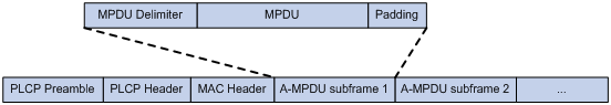
MSDU aggregation
An AP or client encapsulates a MAC Service Data Unit (MSDU) with an Ethernet header, and then converts the frame into 802.11 format for forwarding.
MSDU aggregation aggregates multiple MSDUs into one aggregate MSDU (A-MSDU) to reduce PLCP preamble, PLCP header, and MAC header overheads. This improves network throughput and frame forwarding efficiency.
All MSDUs in an A-MSDU must have the same QoS priority, source address, and destination address. When a device receives an A-MSDU, it restores the A-MSDU to multiple MSDUs for processing.
Figure 18 A-MSDU format
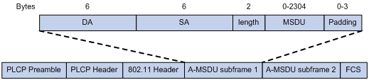
Short GI
802.11 OFDM fragments frames to data blocks for transmission. It uses GI to ensure that the data block transmissions do not interfere with each other and are immune to transmission delays.
The GI used by 802.11a/g is 800 ns. 802.11n supports a short GI of 400 ns, which provides a 10% increase in data rate.
Both the 20 MHz and 40 MHz bandwidth modes support short GI.
LDPC
802.11n introduces the Low-Density Parity Check (LDPC) mechanism to increase the signal-to-noise ratio and enhance transmission quality. LDPC takes effect only when both ends support LDPC.
STBC
The Space-Time Block Coding (STBC) mechanism enhances the reliability of data transmission and does not require clients to have high transmission rates.
MSC indexes
802.11n clients use the rate corresponding to the MCS index to send unicast frames. Non-802.11n clients use the 802.11a/b/g rate to send unicast frames.
The client dot11n-only feature
The client dot11n-only feature enables an AP to accept only 802.11n and 802.11ac clients. Use this feature to prevent low-speed 802.11a/b/g clients from decreasing wireless data transmission performance.
802.11n bandwidth mode
802.11n uses the channel structure of 802.11a/b/g, but it increases the number of data subchannels in each 20 MHz channel to 52. This improves data transmission rate.
802.11n binds two adjacent 20 MHz channels to form a 40 MHz channel (one primary channel and one secondary channel). This provides a simple way to double the data rate.
The bandwidth for a radio varies by bandwidth mode configuration and chip capability.
MIMO modes
Multiple-input and multiple-output (MIMO) enables a radio to send and receive wireless signals through multiple spatial streams. This improves system capacity and spectrum usage without requiring higher bandwidth.
A radio can operate in one of the following MIMO modes:
· 1x1—Sends and receives wireless signals through one spatial stream.
· 2x2—Sends and receives wireless signals through two spatial streams.
· 3x3—Sends and receives wireless signals through three spatial streams.
· 4x4—Sends and receives wireless signals through four spatial streams.
Number of spatial streams supported by a radio varies by device model.
Energy saving
The energy saving feature enables an AP to automatically change the MIMO mode of a radio to 1x1 if no clients associate with the radio.
802.11n protection
When both 802.11n and non-802.11n clients exist in a WLAN, transmission collision might occur because they use different modulation modes. 802.11n protection can avoid such avoidance. It enables 802.11n devices to send RTS/CTS or CTS-to-self packets to inform non-802.11n clients to defer access to the medium.
802.11n devices send RTS/CTS or CTS-to-self packets before sending data only when non-802.11n signals are detected on the channel.
802.11n protection automatically takes effect when non-802.11n clients associate with an 802.11n AP.
|
|
NOTE: 802.11n devices refer to 802.11n and 802.11ac devices. |
The smart antenna feature
|
|
IMPORTANT: · Support for this feature depends on the AP model. · This feature is applicable only to 802.11n and 802.11ac radios. |
The smart antenna feature enables an AP to automatically adjust the antenna parameters based on the client location and channel information to improve signal quality and stability.
You can configure a radio to operate in one of the following smart antenna modes:
· auto—Uses the high availability mode for audio and video packets, and uses the high throughput mode for other packets.
· high-availability—Applicable to WLANs that require stable bandwidth, this mode reduces noise and interference impacts, and provides guaranteed bandwidth for clients.
· high-throughput—Applicable to WLANs that require high performance, this mode enhances signal strength and association capability.
802.11ac functions
|
|
IMPORTANT: When you configure 802.11ac functions for an AP, your configuration fails if another user is configuring 802.11ac functions for the same AP. |
Based on 802.11n, 802.11ac further increases the data transmission rate and improves the network performance by providing higher bandwidth, more spatial streams, and more advanced modulation schemes.
NSSs
If the AP supports an NSS, it supports all VHT-MCS indexes for the NSS.
802.11ac clients use the rate corresponding to the VHT-MCS index for the NSS to send unicast frames. Non-802.11ac clients use the 802.11a/b/g/n rate to send unicast frames.
The client dot11ac-only feature
To prevent low-speed 802.11a/b/g/n clients from decreasing wireless data transmission performance, you can enable the client dot11ac-only feature for an AP to accept only 802.11ac clients.
802.11ac bandwidth mode
802.11ac uses the channel structure of 802.11n and increases the maximum bandwidth from 40 MHz to 80 MHz. 802.11ac can bind two adjacent 20 MHz channels to form a 40 MHz channel, and bind two adjacent 40 MHz channels to form an 80 MHz channel.
Figure 19 802.11ac bandwidth modes
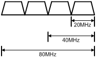
Configuration restrictions and guidelines
When you configure radio management, follow these restrictions and guidelines:
· When you change the mode of a radio, the system automatically adjusts the channel and power parameters for the radio.
Modifying the mode of an enabled radio logs off all associated clients.
· When you set the maximum transmit power, make sure the maximum transmit power is within the transmit power range supported by a radio.
· When you set MSC indexes for an 802.11n AP, follow these restrictions and guidelines:
¡ If you do not set a multicast MCS index, 802.11n clients and the AP use the 802.11a/b/g multicast rate to send multicast frames. If you set a multicast MCS index, one of following events occurs:
- The AP and clients use the rate corresponding to the multicast MCS index to send multicast frames if all clients are 802.11n clients.
- The AP and clients use the 802.11a/b/g multicast rate to send multicast frames if any non-802.11n clients exist.
¡ When you set the maximum mandatory or supported MCS index, you are specifying a range. For example, if you set the maximum mandatory MCS index to 5, rates corresponding to MCS indexes 0 through 5 are configured as 802.11n mandatory rates.
· When you set NSSs for an 802.11ac AP, follow these restrictions and guidelines
¡ If you do not set a multicast NSS, 802.11ac clients and the AP use the 802.11a/b/g/n multicast rate to send multicast frames. If you set a multicast NSS and specify a VHT-MCS index, the following situations occur:
- The AP and clients use the rate corresponding to the VHT-MCS index for the NSS to send multicast frames if all clients are 802.11ac clients.
- The AP and clients use the 802.11a/b/g/n multicast rate to send multicast frames if any non-802.11ac clients exist.
- The maximum mandatory NSS or supported NSS determines a range of 802.11 rates. For example, if the maximum mandatory NSS is 5, rates corresponding to VHT-MCS indexes for NSSs 1 through 5 will be 802.11ac mandatory rates.
WLAN RRM
WLAN Radio Resource Management (RRM) provides an intelligent and scalable radio management solution. RRM enables an AC to monitor its associated radios and perform radio resource monitoring, dynamic frequency selection (DFS), and transmit power control (TPC). This allows a WLAN to adapt to environment changes and maintain the optimal radio resource condition.
Dynamic frequency selection
With DFS, the AC selects an optimal channel for each radio in real time to avoid co-channel interference and interference from other radio sources.
The following factors determine DFS:
· Error code rate—Physical layer error code rate and CRC errors.
· Interference—Influence of all wireless signals on wireless services.
· Retransmission—Data retransmission by radios if they do not receive ACK messages from the AC.
· Radar signal—Radar signals detected on the current channel. In this case, the AC selects a new channel and immediately notifies a radio to change its working channel.
The AC selects a new channel for a radio by using the following process:
1. Detects the current channel and selects an optimal channel if any of the DFS thresholds is reached. The DFS thresholds include CRC error, interference, and retransmission.
2. Compares the quality between old and new channels. The radio does not use the new channel until the quality gap between the new channel and the old channel exceeds the tolerance level.
Transmit power control
TPC enables an AC to dynamically control access point transmit power based on real-time WLAN conditions. It can achieve desired RF coverage while avoiding channel interference between radios.
The following factors determine TPC:
· Neighbor number threshold.
· Power-detecting radio—Neighbor radio that performs power detection.
· Power adjustment threshold.
When TPC is enabled, a radio adjusts its transmit power as follows:
· If the neighbor number threshold is reached for the radio, the radio adjusts its transmit power in the following ways:
¡ Decreases its transmit power when the power-detecting radio detects that the power of the radio is a minimum of 6 dBm higher than the power adjustment threshold.
¡ Increases its transmit power when the power-detecting radio detects that the power of the radio is a minimum of 3 dBm lower than the power adjustment threshold.
· If the neighbor number threshold is not reached for the radio, the radio uses the maximum transmit power.
You can configure one of the following TPC modes for an AP:
· Custom—Default mode. You can modify the TPC parameters.
· Coverage—System-defined mode. You cannot modify the TPC parameters. This mode provides large signal coverage and is applicable to low-density WLANs.
· Density—System-defined mode. You cannot modify the TPC parameters. This mode is more immune to signal interference and is applicable to high-density WLANs.
Channel scanning
When both DFS and TPC are disabled, you can enable channel scanning to monitor the channel usage and interference.
After you enable channel scanning, an AP scans the wireless environment and sends the collected data to the AC. Then, you can monitor the channel usage and interference through channel reports and neighbor reports that are generated by the AC.
RRM holddown group
To prevent frequent channel or power adjustments from affecting wireless services, you can add the specified radios to an RRM holddown group. Each time the channel or power of a radio in the RRM holddown group changes, the system starts the channel or power holddown timer for the radio. The channel or power for the radio remains unchanged before the channel or power holddown timer expires.
Baseline
A baseline records the channel, transmit power, and parameter information of a specific time for one radio, radios on APs of the same model in an AP group, or all radios. You can apply a baseline to enable a radio to use the configuration saved in the baseline.
A baseline cannot be applied to a radio when one of the following conditions exists:
· The radio does not exist.
· The radio is disabled.
· The radio mode saved in the baseline does not match the actual radio mode.
· The region code saved in the baseline does not match the actual region code.
· The wireless service does not take effect.
· The working channel saved in the baseline is invalid.
· The bandwidth saved in the baseline does not match the actual bandwidth.
· The working channel of the radio is manually specified.
· The working channel of the radio is locked.
· The radio is in the channel holddown time.
· The power of the radio is locked.
· The radio is in the power holddown time.
· The transmit power saved in the baseline is smaller than the configured minimum transmit power.
· The transmit power saved in the baseline is larger than the configured maximum transmit power.
WLAN load balancing
WLAN load balancing dynamically loads balance clients across APs to ensure wireless service quality and adequate bandwidth for clients in high-density WLANs.
Load balancing types
The AC supports the following load balancing types:
· Radio based—The AC performs load balancing among all APs connected to the AC.
· Load balancing group based—You add the radios of desired APs to a load balancing group. The AC does not perform load balancing on radios that do not belong to the load balancing group.
Load balancing modes
The AC supports session-mode, traffic-mode, and bandwidth-mode load balancing. It performs load balancing of a specific mode when the following conditions are met:
· The specified session/traffic/bandwidth threshold is reached.
· The specified session/traffic/bandwidth gap threshold is reached.
Load balancing parameters
WLAN load balancing uses the following parameters:
· Load balancing RSSI threshold—A client might be detected by multiple APs. An AP considers a client not detected if the client's RSSI is lower than the load balancing RSSI threshold. If only one AP can detect the client, the AP increases the access probability for the client even if it is overloaded.
· Maximum number of denials for association requests—If the number of times that an AP rejects a client reaches the specified maximum number of denials for association requests, the AP accepts the association request of the client.
Band navigation
As shown in Figure 20, band navigation is enabled in the WLAN. Client 1 is associated with the 5 GHz radio and Client 2 is associated with the 2.4 GHz radio. When the dual-band client Client 3 requests to associate with the 2.4 GHz radio, the AP rejects Client 3 and directs it to the 5 GHz radio.
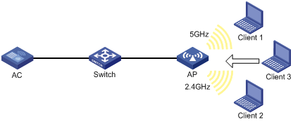
Client probing
After you enable client probing on the radio of an AP, the AP scans channels to collect client information. You can view the client information on the Monitoring > Client Proximity Sensor page.
Do not enable WIPS and client probing simultaneously.
Wireless locating
Wireless locating uses WiFi-based Radio Frequency Identification (RFID) and 802.11 devices to locate, track and, monitor specific devices. AeroScout, BLE, CUPID, and RF fingerprinting locating are supported.
Locating system
A wireless locating system contains the following parts:
· Devices to locate—802.11 devices that can send wireless packets. For AeroScout locating, 802.11 devices include Tags (small wireless devices that can only send 802.11 packets periodically) and MUs (all 802.11 devices except Tags).
· Locating information receiver—802.11 APs or other 802.11 devices that can receive wireless packets.
· Locating server—A server on which the locating software runs.
Wireless locating mechanism
Wireless locating operates as follows:
1. APs discover the locating server.
¡ For AeroScout locating, the location server sends a set configuration message to an AP before notifying the AP to collect location information. The set configuration message contains the the type of devices to locate, destination multicast MAC address, and the IP address and port number of the location server. The AP saves the IP address and port number in the flash memory and uses them to communicate with the location server.
¡ For other locating methods, APs send locating packets to the specified locating server.
2. APs collect locating information.
3. Upon receiving packets from devices to locate, APs encapsulate the packets and the collected locating information in locating packets, and send them to the locating server.
4. The locating server calculates the locations of the devices.
Packet processing
Channel matching
In wireless networks, APs might receive wireless packets from non-working channels. The RSSI values of these packets are lower than the real RSSI values of the channels where the packets are received, so these packets are not suitable for location calculation.
To address this issue, APs for AeroScout locating perform channel matching as follows:
· Packets from Tags are transmitted through multiple channels, and the packets carry the channel information. After receiving such a packet, an AP sends the packet to the locating server if the channel carried in the packet is the same as the current working channel of the AP. If not, the AP discards the packet.
· Packets from MUs do not carry the channel information. After receiving such a packet, an AP sends the packet to the locating server for channel matching.
Packet dilution
Packet dilution controls the number of locating packets from an AP to the locating server.
The dilution factor specifies wireless packet number threshold for sending a locating packet. For example, if you set the dilution factor to 100, the AP sends a locating packet every time it receives 100 wireless packets from a client (excluding management and broadcast packets).
To avoid affecting locating accuracy, you can set a dilution timeout timer. If the number of wireless packets does not reach the dilution factor when the dilution timeout timer expires, the AP sends the most recent frame it received to the locating server.
Network security
QoS
QoS policies
In data communications, Quality of Service (QoS) provides differentiated service guarantees for diversified traffic in terms of bandwidth, delay, jitter, and drop rate, all of which can affect QoS.
By associating a traffic behavior with a traffic class in a QoS policy, you apply QoS actions in the traffic behavior to the traffic class.
Traffic class
A traffic class defines a set of match criteria for classifying traffic.
Traffic behavior
A traffic behavior defines a set of QoS actions to take on packets.
QoS policy
A QoS policy associates traffic classes with traffic behaviors and performs the actions in each behavior on its associated traffic class.
Applying a QoS policy
You can apply a QoS policy to the following destinations:
· Interface—The QoS policy takes effect on the traffic sent or received on the interface. The QoS policy applied to the outgoing traffic on an interface or PVC does not regulate local packets. Local packets refer to critical protocol packets sent by the local system for operation maintenance. The most common local packets include link maintenance, routing, LDP, RSVP, and SSH packets.
· Globally—The QoS policy takes effect on the traffic sent or received on all ports.
Priority mapping
When a packet arrives, a device assigns values of priority parameters to the packet for the purpose of queue scheduling and congestion control.
Priority mapping allows you to modify the priority values of the packet according to priority mapping rules. The priority parameters decide the scheduling priority and forwarding priority of the packet.
Port priority
When a port is configured with a priority trust mode, the device trusts the priorities included in incoming packets. The device can automatically resolves the priorities or flag bits included in packets. The device then maps the trusted priority to the target priority types and values according to the priority maps.
When a port is not configured with a priority trust mode and is configured with a port priority, the device does not trust the priorities included in incoming packets. The device uses its port priority to look for priority parameters for the incoming packets.
The available priority trust modes include the following types:
· Untrust—Does not trust any priority included in packets.
· Dot1p—Trusts the 802.1p priorities included in packets.
· DSCP—Trusts the DSCP priorities included in IP packets.
Priority map
The device provides three priority maps: 802.1p-lp, DSCP-802.1p, and DSCP-DSCP. If a default priority map cannot meet your requirements, you can modify the priority map as required.
802.1X
802.1X is a port-based network access control protocol that controls network access by authenticating the devices connected to 802.1X-enabled LAN ports.
802.1X architecture
802.1X includes the following entities:
· Client—A user terminal seeking access to the LAN. The terminal must have 802.1X software to authenticate to the access device.
· Access device—Authenticates the client to control access to the LAN. In a typical 802.1X environment, the access device uses an authentication server to perform authentication.
· Authentication server—Provides authentication services for the access device. The authentication server first authenticates 802.1X clients by using the data sent from the access device. Then, the server returns the authentication results to the access device to make access decisions. The authentication server is typically a RADIUS server. In a small LAN, you can use the access device as the authentication server.
802.1X authentication methods
The access device can perform EAP relay or EAP termination to communicate with the RADIUS server.
· EAP termination—The access device performs the following operations in EAP termination mode:
a. Terminates the EAP packets received from the client.
b. Encapsulates the client authentication information in standard RADIUS packets.
c. Uses PAP or CHAP to authenticate to the RADIUS server.
CHAP sends ciphertext passwords to the RADIUS server, and PAP sends plaintext passwords to the RADIUS server.
· EAP relay—The access device uses EAPOR packets to send authentication information to the RADIUS server.
Access control methods
The following access control methods are supported:
· Port-based access control—Once an 802.1X user passes authentication on a port, all subsequent users can access the network through the port without authentication. When the authenticated user logs off, all other users are logged off.
· MAC-based access control—Each user is separately authenticated on a port. When a user logs off, the other online users are not affected.
Port authorization state
You can control the authorization state of a port by using the following options:
· Authorized—Places the port in the authorized state, enabling users on the port to access the network without authentication.
· Unauthorized—Places the port in the unauthorized state, denying any access requests from users on the port.
· Auto—Places the port initially in unauthorized state to allow only EAPOL packets to pass. After a user passes authentication, sets the port to the authorized state to allow access to the network.
Periodic online user reauthentication
Periodic online user reauthentication tracks the connection status of online users, and updates the authorization attributes assigned by the server. The attributes include the ACL, VLAN, and user profile-based QoS. The reauthentication interval is user configurable.
Online user handshake
The online user handshake feature checks the connectivity status of online 802.1X users. The access device sends handshake messages to online users at the handshake interval. If the device does not receive any responses from an online user after it has made the maximum handshake attempts, the device sets the user to offline state.
You can also enable the online user handshake security feature to check authentication information in the handshake packets from clients. With this feature, the device prevents 802.1X users who use illegal client software from bypassing iNode security check such as dual network interface cards (NICs) detection.
Authentication trigger
The access device initiates authentication if a client cannot send EAPOL-Start packets. One example is the 802.1X client available with Windows XP.
The access device supports the following modes:
· Unicast trigger mode—Upon receiving a frame from an unknown MAC address, the access device sends an Identity EAP-Request packet out of the receiving port to the MAC address. The device retransmits the packet if no response has been received within the specified interval.
· Multicast trigger mode—The access device multicasts Identity EAP-Request packets periodically (every 30 seconds by default) to initiate 802.1X authentication.
Auth-Fail VLAN
The 802.1X Auth-Fail VLAN on a port accommodates users who have failed 802.1X authentication because of the failure to comply with the organization security strategy. For example, the VLAN accommodates users who have entered a wrong password. The Auth-Fail VLAN does not accommodate 802.1X users who have failed authentication for authentication timeouts or network connection problems.
The access device handles VLANs on an 802.1X-enabled port based on its 802.1X access control method.
· On a port that performs port-based access control:
|
Authentication status |
VLAN manipulation |
|
A user fails 802.1X authentication. |
The device assigns the Auth-Fail VLAN to the port as the PVID. All 802.1X users on this port can access only resources in the Auth-Fail VLAN. |
|
A user in the 802.1X Auth-Fail VLAN fails 802.1X reauthentication |
The Auth-Fail VLAN is still the PVID on the port, and all 802.1X users on this port are in this VLAN. |
|
A user passes 802.1X authentication. |
· The device assigns the authorization VLAN of the user to the port as the PVID, and it removes the port from the Auth-Fail VLAN. After the user logs off, the guest VLAN is assigned to the port as the PVID. If no guest VLAN is configured, the initial PVID of the port is restored. · If the authentication server does not authorize a VLAN, the initial PVID of the port applies. The user and all subsequent 802.1X users are assigned to the initial PVID. After the user logs off, the PVID remains unchanged. |
· On a port that performs MAC-based access control:
|
Authentication status |
VLAN manipulation |
|
A user fails 802.1X authentication. |
The device maps the MAC address of the user to the 802.1X Auth-Fail VLAN. The user can access only resources in the Auth-Fail VLAN. |
|
A user in the 802.1X Auth-Fail VLAN fails 802.1X reauthentication. |
The user is still in the Auth-Fail VLAN. |
|
A user in the 802.1X Auth-Fail VLAN passes 802.1X authentication. |
The device remaps the MAC address of the user to the authorization VLAN. If the authentication server does not authorize a VLAN, the device remaps the MAC address of the user to the initial PVID on the port. |
Guest VLAN
The 802.1X guest VLAN on a port accommodates users who have not performed 802.1X authentication. Once a user in the guest VLAN passes 802.1X authentication, it is removed from the guest VLAN and can access authorized network resources.
The access device handles VLANs on an 802.1X-enabled port based on its 802.1X access control method.
· On a port that performs port-based access control:
|
Authentication status |
VLAN manipulation |
|
A user has not passed 802.1X authentication. |
The device assigns the 802.1X guest VLAN to the port as the PVID. All 802.1X users on this port can access only resources in the guest VLAN. If no 802.1X guest VLAN is configured, the access device does not perform any VLAN operation. |
|
A user in the 802.1X guest VLAN fails 802.1X authentication. |
If an 802.1X Auth-Fail VLAN (see "Auth-Fail VLAN") is available, the device assigns the Auth-Fail VLAN to the port as the PVID. All users on this port can access only resources in the Auth-Fail VLAN. If no Auth-Fail VLAN is configured, the PVID on the port is still the 802.1X guest VLAN. All users on the port are in the guest VLAN. |
|
A user in the 802.1X guest VLAN passes 802.1X authentication. |
· The device assigns the authorization VLAN of the user to the port as the PVID, and it removes the port from the 802.1X guest VLAN. After the user logs off, the initial PVID of the port is restored. · If the authentication server does not authorize a VLAN, the initial PVID applies. The user and all subsequent 802.1X users are assigned to the initial port VLAN. After the user logs off, the port VLAN remains unchanged. NOTE: The initial PVID of an 802.1X-enabled port refers to the PVID used by the port before the port is assigned to any 802.1X VLANs. |
· On a port that performs MAC-based access control:
|
Authentication status |
VLAN manipulation |
|
A user has not passed 802.1X authentication and is in the authentication process. |
The device creates a mapping between the MAC address of the user and the 802.1X guest VLAN. The user can access only resources in the guest VLAN. |
|
A user in the 802.1X guest VLAN fails 802.1X authentication. |
If an 802.1X Auth-Fail VLAN is available, the device remaps the MAC address of the user to the Auth-Fail VLAN. The user can access only resources in the Auth-Fail VLAN. If no 802.1X Auth-Fail VLAN is configured, the user is still in the 802.1X guest VLAN. |
|
A user in the 802.1X guest VLAN passes 802.1X authentication. |
The device remaps the MAC address of the user to the authorization VLAN. If the authentication server does not authorize a VLAN, the device remaps the MAC address of the user to the initial PVID on the port. |
Critical VLAN
The 802.1X critical VLAN on a port accommodates 802.1X users who have failed authentication because none of the RADIUS servers in their ISP domain is reachable. The critical VLAN feature takes effect when 802.1X authentication is performed only through RADIUS servers. If an 802.1X user fails local authentication after RADIUS authentication, the user is not assigned to the critical VLAN.
The access device handles VLANs on an 802.1X-enabled port based on its 802.1X access control method.
· On a port that performs port-based access control:
|
Authentication status |
VLAN manipulation |
|
A user that has not been assigned to any VLAN fails 802.1X authentication because all the RADIUS servers are unreachable. |
The device assigns the critical VLAN to the port as the PVID. The 802.1X user and all subsequent 802.1X users on this port can access only resources in the 802.1X critical VLAN. |
|
A user in the 802.1X critical VLAN fails authentication because all the RADIUS servers are unreachable. |
The critical VLAN is still the PVID of the port, and all 802.1X users on this port are in this VLAN. |
|
A user in the 802.1X critical VLAN fails authentication for any other reasons except for unreachable servers. |
If an 802.1X Auth-Fail VLAN has been configured, the PVID of the port changes to the Auth-Fail VLAN ID, and all 802.1X users on this port are moved to the Auth-Fail VLAN. If no 802.1X Auth-Fail VLAN is configured, the initial PVID of the port is restored. |
|
A user in the 802.1X critical VLAN passes 802.1X authentication. |
· The device assigns the authorization VLAN of the user to the port as the PVID, and it removes the port from the 802.1X critical VLAN. After the user logs off, the guest VLAN ID changes to the PVID. If no 802.1X guest VLAN is configured, the initial PVID of the port is restored. · If the authentication server (either the local access device or a RADIUS server) does not authorize a VLAN, the initial PVID of the port applies. The user and all subsequent 802.1X users are assigned to this port VLAN. After the user logs off, the PVID remains unchanged. |
|
A user in the 802.1X guest VLAN fails authentication because all the RADIUS servers are unreachable. |
The device assigns the 802.1X critical VLAN to the port as the PVID, and all 802.1X users on this port are in this VLAN. |
|
A user in the 802.1X Auth-Fail VLAN fails authentication because all the RADIUS servers are unreachable. |
The PVID of the port remains unchanged. All 802.1X users on this port can access only resources in the 802.1X Auth-Fail VLAN. |
|
A user who has passed authentication fails reauthentication because all the RADIUS servers are unreachable, and the user is logged out of the device. |
The device assigns the 802.1X critical VLAN to the port as the PVID. |
· On a port that performs MAC-based access control:
|
Authentication status |
VLAN manipulation |
|
A user that has not been assigned to any VLAN fails 802.1X authentication because all the RADIUS servers are unreachable. |
The device maps the MAC address of the user to the 802.1X critical VLAN. The user can access only resources in the 802.1X critical VLAN. |
|
A user in the 802.1X critical VLAN fails authentication because all the RADIUS servers are unreachable. |
The user is still in the critical VLAN. |
|
A user in the 802.1X critical VLAN fails 802.1X authentication for any other reasons except for unreachable servers. |
If an 802.1X Auth-Fail VLAN has been configured, the device remaps the MAC address of the user to the Auth-Fail VLAN ID. If no 802.1X Auth-Fail VLAN has been configured, the device remaps the MAC address of the user to the guest VLAN. |
|
A user in the 802.1X critical VLAN passes 802.1X authentication. |
The device remaps the MAC address of the user to the authorization VLAN. If the authentication server (either the local access device or a RADIUS server) does not authorize a VLAN to the user, the device remaps the MAC address of the user to the initial PVID on the port. |
|
A user in the 802.1X guest VLAN fails authentication because all the RADIUS servers are unreachable. |
The device remaps the MAC address of the user to the 802.1X critical VLAN. The user can access only resources in the 802.1X critical VLAN. |
|
A user in the 802.1X Auth-Fail VLAN fails authentication because all the RADIUS servers are unreachable. |
The user remains in the 802.1X Auth-Fail VLAN. |
Mandatory authentication domain
You can place all 802.1X users in a mandatory authentication domain for authentication, authorization, and accounting on a port. No user can use an account in any other domain to access the network through the port. The implementation of a mandatory authentication domain enhances the flexibility of 802.1X access control deployment.
EAD assistant
Endpoint Admission Defense (EAD) is an integrated endpoint access control solution to improve the threat defensive capability of a network. The solution enables the security client, security policy server, access device, and third-party server to operate together. If a terminal device seeks to access an EAD network, it must have an EAD client, which performs 802.1X authentication.
The EAD assistant feature enables the access device to redirect a user who is seeking to access the network to download and install an EAD client. This feature eliminates the administrative task to deploy EAD clients.
802.1X SmartOn
The SmartOn feature is mutually exclusive with the 802.1X online user handshake feature.
When the device sends a unicast EAP-Request/Notification packet to the client, it starts the SmartOn client timeout timer.
· If the device does not receive any EAP-Response/Notification packets from the client within the timeout timer, it retransmits the EAP-Request/Notification packet to the client. After the device has made the maximum retransmission attempts but received no response, it stops the 802.1X authentication process for the client.
· If the device receives an EAP-Response/Notification packet within the timer or before the maximum retransmission attempts have been made, it starts the SmartOn authentication. If the SmartOn switch ID and the MD5 digest of the SmartOn password in the packet match those on the device, 802.1X authentication continues for the client. Otherwise, the device denies the client's 802.1X authentication request.
ISP domains
The device manages users based on ISP domains. An ISP domain includes authentication, authorization, and accounting methods for users. The device determines the ISP domain and access type of a user. It also uses the methods configured for the access type in the domain to control the user's access.
The device supports the following authentication methods:
· No authentication—This method trusts all users and does not perform authentication. For security purposes, do not use this method.
· Local authentication—The device authenticates users by itself, based on the locally configured user information including the usernames, passwords, and attributes. Local authentication allows high speed and low cost, but the amount of information that can be stored is limited by the size of the storage space.
· Remote RADIUS authentication—The device works with a remote RADIUS server to authenticate users. The server manages user information in a centralized manner. Remote authentication provides high capacity, reliable, and centralized authentication services for multiple devices. You can configure backup methods to be used when the remote server is not available.
The device supports the following authorization methods:
· No authorization—The device performs no authorization exchange. The following default authorization information applies after users pass authentication:
¡ Non-login users can access the network.
¡ FTP, SFTP, and SCP users have the root directory of the device set as the working directory. However, the users do not have permission to access the root directory.
¡ Other login users obtain the default user role.
· Local authorization—The device performs authorization according to the user attributes locally configured for users.
· Remote RADIUS authorization—The device works with a remote RADIUS server to authorize users. RADIUS authorization is bound with RADIUS authentication. RADIUS authorization can work only after RADIUS authentication is successful, and the authorization information is included in the Access-Accept packet. You can configure backup methods to be used when the remote server is not available.
The device supports the following accounting methods:
· No accounting—The device does not perform accounting for the users.
· Local accounting—Local accounting is implemented on the device. It counts and controls the number of concurrent users who use the same local user account, but does not provide statistics for charging.
· Remote RADIUS accounting—The device works with a remote RADIUS server for accounting. You can configure backup methods to be used when the remote server is not available.
On the device, each user belongs to one ISP domain. The device determines the ISP domain to which a user belongs based on the username entered by the user at login.
AAA manages users in the same ISP domain based on the users' access types. The device supports the following user access types:
· LAN—LAN users must pass 802.1X authentication to come online.
· Login—Login users include Telnet, FTP, and terminal users who log in to the device. Terminal users can access through a console or AUX port.
· Portal—Portal users.
In a networking scenario with multiple ISPs, the device can connect to users of different ISPs. The device supports multiple ISP domains, including a system-defined ISP domain named system. One of the ISP domains is the default domain. If a user does not provide an ISP domain name for authentication, the device considers the user belongs to the default ISP domain.
The device chooses an authentication domain for each user in the following order:
· The authentication domain specified for the access module (for example, 802.1X).
· The ISP domain in the username.
· The default ISP domain of the device.
RADIUS
RADIUS protocol
Remote Authentication Dial-In User Service (RADIUS) is a distributed information interaction protocol that uses a client/server model. The protocol can protect networks against unauthorized access and is often used in network environments that require both high security and remote user access.
The RADIUS client runs on the NASs located throughout the network. It passes user information to RADIUS servers and acts on the responses to, for example, reject or accept user access requests.
The RADIUS server runs on the computer or workstation at the network center and maintains information related to user authentication and network service access.
RADIUS uses UDP to transmit packets. The RADIUS client and server exchange information with the help of shared keys.
When AAA is implemented by a remote RADIUS server, configure the RADIUS server settings on the device that acts as the NAS for the users.
Enhanced RADIUS features
The device supports the following enhanced RADIUS features:
· Accounting-on—This feature enables the device to automatically send an accounting-on packet to the RADIUS server after a reboot. Upon receiving the accounting-on packet, the RADIUS server logs out all online users so they can log in again through the device. Without this feature, users cannot log in again after the reboot, because the RADIUS server considers them to come online.
You can configure the interval for which the device waits to resend the accounting-on packet and the maximum number of retries.
The RADIUS server must run on H3C IMC to correctly log out users when a card reboots on the distributed device to which the users connect.
· Session-control—A RADIUS server running on H3C IMC can use session-control packets to inform disconnect or dynamic authorization change requests. Enable session-control on the device to receive RADIUS session-control packets on UDP port 1812.
BYOD
Bring Your Own Device (BYOD) allows employees to access privileged company data and applications by using personal mobile devices at the workplace, for example, laptops, tablets, and smart phones. BYOD solutions can provide different authentication and authorization services based on the user identities, endpoint types, and access scenarios.
BYOD endpoint identification rules
A BYOD endpoint identification rule defines the mapping between an endpoint type and a fingerprint string. The device obtains fingerprint information from the authentication request of an endpoint, and matches the fingerprint with the rules for the associated endpoint type.
BYOD authorization supports the following endpoint fingerprints:
· DHCP Option 55 fingerprint—Parameter request list option. The option is used by an endpoint to request specific configuration parameters.
· HTTP user agent fingerprint—Located in the header of HTTP requests to carry information about the endpoint operating system, Web browser, and versions.
· MAC address fingerprint—OUI of the endpoint or MAC address range to which the endpoint belongs.
The device matches fingerprint information for an endpoint in the following order:
1. DHCP Option 55 fingerprint.
2. HTTP user agent fingerprint.
3. MAC address fingerprint.
The system has predefined BYOD endpoint identification rules. You can also configure BYOD endpoint identification rules depending on the network requirements.
BYOD authorization
BYOD authorization attributes are assigned based on endpoint types to user groups and apply to users who have passed local authentication. After the device identifies the endpoint type of a user, it assigns BYOD authorization attributes to the user according to the settings of the user group for the user.
Local users
The device performs local authentication, authorization, and accounting based on the locally configured user information, including the username, password, and authorization attributes. Each local user is identified by the username.
User groups simplify local user configuration and management. A user group contains a group of local users and has a set of local user attributes. The user attributes of a user group apply to all users in this group.
Guest management
Guest management enables you to manage accounts and define access authorities for guests. It includes the following functions:
· Creating a guest—You can manually create a guest and configure attributes for the guest.
· Importing guests—You can import a .csv file that contains the guest information to enable the device to automatically generate guests.
· Bulk generating guests—You can configure the system to automatically generate multiple guests and assign usernames and passwords to the guests.
· Exporting guests—You can export the guest information to a .csv file.
· Guest registration and approval—The guest registration and approval process is as follows:
a. The guest enters the registration information including username, password, and email address on the pushed webpage.
b. Upon receiving the registration information, the device records the information and sends a notification to the guest administrator.
c. Upon receiving the notification, the guest administrator approves the guest on the webpage.
d. The device automatically creates the guest and generates related attributes.
The device creates the guest only if the guest administrator approves the guest within the timeout period. If the guest administrator does not approve the guest within the timeout period, the device deletes the guest information.
e. After creating the guest, the device sends a notification containing the guest password and validity period to the guest or receptionist.
f. Upon receiving the notification, the guest can use the registered account to access the network.
· Deleting expired guests—The device periodically checks the guests and deletes expired guests.
· Email notifications—The device can send notifications to guests, receptionist, and guest administrators.
Access control
Port security
Port security combines and extends 802.1X and MAC authentication to provide MAC-based network access control.
Port security provides the following functions:
· Prevents unauthorized access to a network by checking the source MAC address of inbound traffic.
· Prevents access to unauthorized devices or hosts by checking the destination MAC address of outbound traffic.
· Controls MAC address learning and authentication on a port to ensure that the port learns only source trusted MAC addresses.
A frame is illegal if its source MAC address cannot be learned in a port security mode or it is from a client that has failed 802.1X or MAC authentication. The port security feature automatically takes a predefined action on illegal frames. This automatic mechanism enhances network security and reduces human intervention.
Portal
Portal authentication controls user access to networks. Portal authenticates a user by the username and password the user enters on a portal authentication page. Therefore, portal authentication is also known as Web authentication. When portal authentication is deployed on a network, an access device redirects unauthenticated users to the website provided by a portal Web server. The users can access the resources on the website without authentication. If the users want to access other network resources, they must pass authentication on the website.
Portal authentication is classified into the following types:
· Active authentication—Users visit the authentication website provided by the portal Web server and enter their username and password for authentication.
· Forced authentication—Users are redirected to the portal authentication website for authentication when they visit other websites.
Portal authentication flexibly imposes access control on the access layer and vital data entries. It has the following advantages:
· Allows users to perform authentication through a Web browser without installing client software.
· Provides ISPs with diversified management choices and extended functions. For example, the ISPs can place advertisements, provide community services, and publish information on the authentication page.
· Supports multiple authentication modes. For example, re-DHCP authentication implements a flexible address assignment scheme and saves public IP addresses. Cross-subnet authentication can authenticate users who reside in a different subnet than the access device.
Tools
Packet capture
The packet capture feature captures incoming packets that are to be forwarded in the CPU. The feature displays the captured packets in real time, and allows you to save the captured packets to a .pcap file for future analysis.
Packet capture uses the following modes:
· Local packet capture
Local packet capture saves the captured packets to a file on an FTP server.
· Remote packet capture
Remote packet capture displays the captured packets on a Wireshark client. Before using remote packet capture, you must install the Wireshark software on a PC and connect the PC to the RPCAP service port of the AP. Packets captured on the RPCAP port will be displayed on the Wireshark client.
Filter elements
Packet capture supports capture filters. You can use expressions to match packets to capture.
A capture filter contains a keyword string or multiple keyword strings that are connected by operators.
Keywords include the following types:
· Qualifiers—Fixed keyword strings. For example, you must use the ip qualifier to specify the IPv4 protocol.
· Variables—Values supplied by users in the required format. For example, you can set an IP address to 2.2.2.2 or any other valid values.
A variable must be modified by one or multiple qualifiers. For example, to capture any packets sent from the host at 2.2.2.2, use the filter src host 2.2.2.2.
Operators include the following types:
· Logical operators—Perform logical operations, such as the AND operation.
· Arithmetic operators—Perform arithmetic operations, such as the ADD operation.
· Relational operators—Indicate the relation between keyword strings. For example, the = operator indicates equality.
This document provides basic information about these elements. For more information about capture and display filters, go to http://wiki.wireshark.org/CaptureFilters.
Capture filter keywords
Table 41 and Table 42 describe the qualifiers and variables for capture filters, respectively.
Table 41 Qualifiers for capture filters
|
Category |
Description |
Examples |
|
Protocol |
Matches a protocol. If you do not specify a protocol qualifier, the filter matches any supported protocols. |
· arp—Matches ARP. · icmp—Matches ICMP. · ip—Matches IPv4. · ip6—Matches IPv6. · tcp—Matches TCP. · udp—Matches UDP. |
|
Direction |
Matches packets based on their source or destination location (an IP address or port number). If you do not specify a direction qualifier, the src or dst qualifier applies. |
· src—Matches the source IP address field. · dst—Matches the destination IP address field. · src or dst—Matches the source or destination IP address field. NOTE: The src or dst qualifier applies if you do not specify a direction qualifier. For example, port 23 is equivalent to src or dst port 23. |
|
Type |
Specifies the direction type. |
· host—Matches the IP address of a host. · net—Matches an IP subnet. · port—Matches a service port number. · portrange—Matches a service port range. NOTE: The host qualifier applies if you do not specify any type qualifier. For example, src 2.2.2.2 is equivalent to src host 2.2.2.2. To specify an IPv6 subnet, you must specify the net qualifier. |
|
Others |
Any other qualifiers than the previously described qualifiers. |
· broadcast—Matches broadcast packets. · multicast—Matches multicast and broadcast packets. · less—Matches packets that are less than or equal to a specific size. · greater—Matches packets that are greater than or equal to a specific size. · len—Matches the packet length. · vlan—Matches VLAN packets. |
|
|
NOTE: None of the protocol qualifiers and the broadcast, multicast qualifiers can modify variables. |
Table 42 Variable types for capture filters
|
Variable type |
Description |
Examples |
|
|
Integer |
Represented in binary, octal, decimal, or hexadecimal notation. |
The port 23 expression matches traffic sent to or from port number 23. |
|
|
Integer range |
Represented by hyphenated integers. |
The portrange 100-200 expression matches traffic sent to or from any ports in the range of 100 to 200. |
|
|
IPv4 address |
Represented in dotted decimal notation. |
The src 1.1.1.1 expression matches traffic sent from the IPv4 host at 1.1.1.1. |
|
|
IPv6 address |
Represented in colon hexadecimal notation. |
The dst host 1::1 expression matches traffic sent to the IPv6 host at 1::1. |
|
|
IPv4 subnet |
Represented by an IPv4 network ID or an IPv4 address with a mask. |
Both of the following expressions match traffic sent to or from the IPv4 subnet 1.1.1.0/24: · src 1.1.1. · src net 1.1.1.0/24. |
|
|
IPv6 network segment |
Represented by an IPv6 address with a prefix length. |
The dst net 1::/64 expression matches traffic sent to the IPv6 network 1::/64. |
|
Capture filter operators
Capture filters support logical operators (Table 43), arithmetic operators (Table 44), and relational operators (Table 45). Logical operators can use both alphanumeric and nonalphanumeric symbols. Arithmetic and relational operators can use only nonalphanumeric symbols.
Logical operators are left associative. They group from left to right. The not operator has the highest priority. The and and or operators have the same priority.
Table 43 Logical operators for capture filters
|
Nonalphanumeric symbol |
Alphanumeric symbol |
Description |
|
! |
not |
Reverses the result of a condition. Use this operator to capture traffic that matches the opposite value of a condition. For example, to capture non-HTTP traffic, use not port 80. |
|
&& |
and |
Joins two conditions. Use this operator to capture traffic that matches both conditions. For example, to capture non-HTTP traffic that is sent to or from 1.1.1.1, use host 1.1.1.1 and not port 80. |
|
|| |
or |
Joins two conditions. Use this operator to capture traffic that matches either of the conditions. For example, to capture traffic that is sent to or from 1.1.1.1 or 2.2.2.2, use host 1.1.1.1 or host 2.2.2.2. |
Table 44 Arithmetic operators for capture filters
|
Nonalphanumeric symbol |
Description |
|
+ |
Adds two values. |
|
- |
Subtracts one value from another. |
|
* |
Multiplies one value by another. |
|
/ |
Divides one value by another. |
|
& |
Returns the result of the bitwise AND operation on two integral values in binary form. |
|
| |
Returns the result of the bitwise OR operation on two integral values in binary form. |
|
<< |
Performs the bitwise left shift operation on the operand to the left of the operator. The right-hand operand specifies the number of bits to shift. |
|
>> |
Performs the bitwise right shift operation on the operand to the left of the operator. The right-hand operand specifies the number of bits to shift. |
|
[ ] |
Specifies a byte offset relative to a protocol layer. This offset indicates the byte where the matching begins. You must enclose the offset value in the brackets and specify a protocol qualifier. For example, ip[6] matches the seventh byte of payload in IPv4 packets (the byte that is six bytes away from the beginning of the IPv4 payload). |
Table 45 Relational operators for capture filters
|
Nonalphanumeric symbol |
Description |
|
= |
Equal to. For example, ip[6]=0x1c matches an IPv4 packet if its seventh byte of payload is equal to 0x1c. |
|
!= |
Not equal to. For example, len!=60 matches a packet if its length is not equal to 60 bytes. |
|
> |
Greater than. For example, len>100 matches a packet if its length is greater than 100 bytes. |
|
< |
Less than. For example, len<100 matches a packet if its length is less than 100 bytes. |
|
>= |
Greater than or equal to. For example, len>=100 matches a packet if its length is greater than or equal to 100 bytes. |
|
<= |
Less than or equal to. For example, len<=100 matches a packet if its length is less than or equal to 100 bytes. |
Building a capture filter
This section provides the most commonly used expression types for capture filters.
Logical expression
Use this type of expression to capture packets that match the result of logical operations.
Logical expressions contain keywords and logical operators. For example:
· not port 23 and not port 22—Captures packets with a port number that is not 23 or 22.
· port 23 or icmp—Captures packets with a port number 23 or ICMP packets.
In a logical expression, a qualifier can modify more than one variable connected by its nearest logical operator. For example, to capture packets sourced from IPv4 address 192.168.56.1 or IPv4 network 192.168.27, use either of the following expressions:
· src 192.168.56.1 or 192.168.27.
· src 192.168.56.1 or src 192.168.27.
The expr relop expr expression
Use this type of expression to capture packets that match the result of arithmetic operations.
This expression contains keywords, arithmetic operators (expr), and relational operators (relop). For example, len+100>=200 captures packets that are greater than or equal to 100 bytes.
The proto [ expr:size ] expression
Use this type of expression to capture packets that match the result of arithmetic operations on a number of bytes relative to a protocol layer.
This type of expression contains the following elements:
· proto—Specifies a protocol layer.
· []—Performs arithmetic operations on a number of bytes relative to the protocol layer.
· expr—Specifies the arithmetic expression.
· size—Specifies the byte offset. This offset indicates the number of bytes relative to the protocol layer. The operation is performed on the specified bytes. The offset is set to 1 byte if you do not specify an offset.
For example, ip[0]&0xf !=5 captures an IP packet if the result of ANDing the first byte with 0x0f is not 5.
To match a field, you can specify a field name for expr:size. For example, icmp[icmptype]=0x08 captures ICMP packets that contain a value of 0x08 in the Type field.
The vlan vlan_id expression
Use this type of expression to capture 802.1Q tagged VLAN traffic.
This type of expression contains the vlan vlan_id keywords and logical operators. The vlan_id variable is an integer that specifies a VLAN ID. For example, vlan 1 and ip6 captures IPv6 packets in VLAN 1.
To capture 802.1Q tagged traffic, you must use the vlan vlan_id expression prior to any other expressions. An expression matches untagged packets if it does not follow a vlan vlan_id expression. For example:
· vlan 1 and !tcp—Captures VLAN 1-tagged non-TCP packets.
· icmp and vlan 1—Captures untagged ICMP packets that are VLAN 1 tagged. This expression does not capture any packets because no packets can be both tagged and untagged.
System features configuration examples
Network settings configuration examples
Intra-AC roaming configuration example
Network requirements
As shown in Figure 21, configure intra-AC roaming to enable the client to roam from AP 1 to AP 2. The two APs are managed by the same AC.
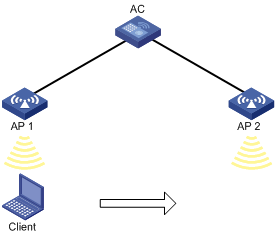
Configuration procedures
1. Click the network view tab at the bottom of the page.
2. Configure a wireless service:
a. From the navigation tree, select Wireless Configuration > Wireless Networks.
b. Add a wireless service:
- Create a wireless service named service.
- Set the SSID to roaming.
- Enable the wireless service.
3. Configure the APs:
a. From the navigation tree, select AP Management. You are placed on the AP tab.
b. Configure AP 1:
- Click the edit icon in the operation column for AP 1.
- Click the wireless service setting tab, and bind the wireless service service to the radio of AP 1.
c. Configure AP 2 in the same way AP 1 is configured.
Verifying the configuration
# On the System View> Network Configuration > Mobility Domain > Roaming page, verify that the client associates with AP 1 before roaming and associates with AP 2 after roaming.
Inter-AC roaming configuration example
Network requirements
As shown in Figure 22, configure inter-AC roaming to enable the client to roam from AP 2 to AP 3 that are managed by different ACs.
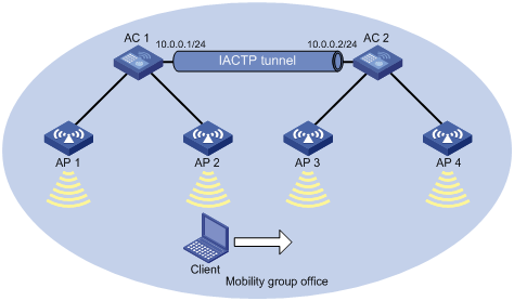
Configuring AC 1
1. Click the network view tab at the bottom of the page.
2. Configure a wireless service:
a. From the navigation tree, select Wireless Configuration > Wireless Networks.
b. Add a wireless service:
- Create a wireless service named service.
- Set the SSID to roaming.
- Enable the wireless service.
3. Configure the APs:
a. From the navigation tree, select AP Management. You are placed on the AP tab.
b. Configure AP 1:
- Click the edit icon in the operation column for AP 1.
- Click the wireless service setting tab, and bind the wireless service service to the radio of AP 1.
c. Configure AP 2 in the same way AP 1 is configured.
4. Click the system view tab at the bottom of the page.
5. Configure a mobility group:
a. From the navigation tree, select Network Configuration > Mobility Domain.
b. On the Roaming tab, perform the following tasks:
- Create a mobility group named office.
- Set the IP address type to IPv4 for IACTP tunnels.
- Specify 10.0.0.1 as the source IP address for establishing IACTP tunnels.
- Add the member device whose IP address is 10.0.0.2 to the mobility group.
- Enable the mobility group.
Configuring AC 2
1. Click the network view tab at the bottom of the page.
2. Configure a wireless service:
a. From the navigation tree, select Wireless Configuration > Wireless Networks.
b. Add a wireless service:
- Create a wireless service named service.
- Set the SSID to roaming.
- Enable the wireless service.
3. Configure the APs:
a. From the navigation tree, select AP Management. You are placed on the AP tab.
b. Configure AP 3:
- Click the edit icon in the operation column for AP 3.
- Click the wireless service setting tab, and bind the wireless service service to the radio of AP 3.
c. Configure AP 4 in the same way AP 3 is configured.
4. Click the system view tab at the bottom of the page.
5. Configure a mobility group:
a. From the navigation tree, select Network Configuration > Mobility Domain.
b. On the Roaming tab, perform the following tasks:
- Create a mobility group named office.
- Set the IP address type to IPv4 for IACTP tunnels.
- Specify 10.0.0.2 as the source IP address for establishing IACTP tunnels.
- Add the member device whose IP address is 10.0.0.1 to the mobility group.
- Enable the mobility group.
Verifying the configuration
# On the System View> Network Configuration > Mobility Domain > Roaming page, verify the following information:
· The client associates with AP 2 managed by AC 1 before roaming.
· The client associates with AP 3 managed by AC 2 after roaming.
Layer 2 static aggregation configuration example
Network requirements
As shown in Figure 23, configure a Layer 2 static aggregation group on both AC 1 and AC 2 to improve the link reliability.

Configuration procedure
1. Configure Ethernet link aggregation on AC 1:
a. Click the system view tab at the bottom of the page.
b. From the navigation tree, select Network Configuration > Network Interfaces.
c. Click the Link Aggregation tab.
d. Configure a Layer 2 aggregation group:
- Add Layer 2 aggregation group 10.
- Configure the aggregation mode as Static.
- Assign ports GigabitEthernet 1/0/1 through GigabitEthernet 1/0/3 to the aggregation group.
2. Configure a VLAN on AC 1:
a. Click the system view tab at the bottom of the page.
b. From the navigation tree, select Network Configuration > VLAN. You are placed on the VLAN tab.
c. Create VLAN 10.
d. Access the details page for VLAN 10 to perform the following tasks:
- Add the port GigabitEthernet 1/0/4 (that connects to Host A) to the untagged port list.
- Add ports GigabitEthernet 1/0/1 through GigabitEthernet 1/0/3 to the tagged port list.
3. Configure AC 2 in the same way AC 1 is configured. (Details not shown.)
Verifying the configuration
1. Access the link aggregation page, and verify that ports GigabitEthernet 1/0/1 through GigabitEthernet 1/0/3 have been assigned to link aggregation group 10.
2. Verify that Host A can ping Host B.
3. Verify that Host A can still ping Host B after a link between AC 1 and AC 2 fails.
Layer 2 dynamic aggregation configuration example
Network requirements
As shown in Figure 24, configure a dynamic Layer 2 aggregation group on both AC 1 and AC 2 to improve the link reliability.
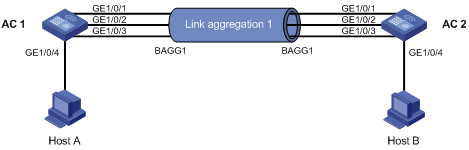
Configuration procedure
1. Configure Ethernet link aggregation on AC 1:
a. Click the system view tab at the bottom of the page.
b. From the navigation tree, select Network Configuration > Network Interfaces.
c. Click the Link Aggregation tab.
d. Configure a Layer 2 aggregation group:
- Add Layer 2 aggregation group 10.
- Configure the aggregation mode as Dynamic.
- Assign ports GigabitEthernet 1/0/1 through GigabitEthernet 1/0/3 to the aggregation group.
2. Configure a VLAN on AC 1:
a. Click the system view tab at the bottom of the page.
b. From the navigation tree, select Network Configuration > VLAN. You are placed on the VLAN tab.
c. Create VLAN 10.
d. Access the details page for VLAN 10 to perform the following tasks:
- Add the port GigabitEthernet 1/0/4 (that connects to Host A) to the untagged port list.
- Add ports GigabitEthernet 1/0/1 through GigabitEthernet 1/0/3 to the tagged port list.
3. Configure AC 2 in the same way AC 1 is configured. (Details not shown.)
Verifying the configuration
1. Access the link aggregation page, and verify that ports GigabitEthernet 1/0/1 through GigabitEthernet 1/0/3 have been assigned to link aggregation group 10.
2. Verify that Host A can ping Host B.
3. Verify that Host A can still ping Host B after a link between AC 1 and AC 2 fails.
PPPoE client configuration example
|
Hardware series |
Model |
Configuration example compatibility |
|
WX1800H series |
WX1804H WX1810H WX1820H WX1840H |
Yes |
|
WX3800H series |
WX3820H WX3840H |
No |
|
WX5800H series |
WX5860H |
No |
Network requirements
As shown in Figure 25, connect the AC to the Internet as a PPPoE client through Layer 3 Ethernet interface GigabitEthernet 1/0/1, and make sure the PC can telnet to the Web interface through interface GigabitEthernet 1/0/2.
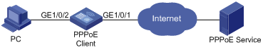
Configuration procedures
|
|
IMPORTANT: After you configure the PPPoE client settings, do not assign addresses to interface GigabitEthernet 1/0/1 manually or through DHCP. |
# Configure the PPPoE server to assign a username and password to the device. (Details not shown.)
# Configure the PPPoE client:
1. Click the system view tab at the bottom of the page.
2. From the navigation tree, select Network Configuration > Network Interfaces.
3. Click the PPPoE tab.
4. Click the ![]() icon.
icon.
5. Select Layer 3 Ethernet interface GigabitEthernet 1/0/1.
6. Enter the username and password, and select an online mode.
7. Select Open the NAT function, and clear the existing address settings on the interface.
8. Click Apply.
Verifying the configuration
# Configure static routes, and then verify that the AC and the PPPoE server can reach other.
MAC address table configuration example
Network requirements
As shown in Figure 26:
· Host A at MAC address 000f-e235-dc71 is connected to interface GigabitEthernet 1/0/1 of the AC and belongs to VLAN 1.
· Host B at MAC address 000f-e235-abcd, which behaved suspiciously on the network, also belongs to VLAN 1.
Configure the MAC address table as follows:
· To prevent MAC address spoofing, add a static entry for Host A in the MAC address table of the AC.
· To drop all frames destined for Host B, add a blackhole MAC address entry for Host B.
· Set the aging timer to 500 seconds for dynamic MAC address entries.
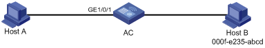
Configuration procedures
1. Click the system view tab at the bottom of the page.
2. From the navigation tree, select Network Configuration > VLAN.
3. Click the MAC tab.
4. Add a static MAC address entry for MAC address 000f-e235-dc71 on GigabitEthernet 1/0/1 that belongs to VLAN 1.
5. Add a blackhole MAC address entry for MAC address 000f-e235-abcd that belongs to VLAN 1.
6. Access the advanced settings page to set the aging timer to 500 seconds for dynamic MAC address entries.
Verifying the configuration
# Access the Network Configuration > VLAN > MAC page to verify that a static and a blackhole MAC address entries have been created.
# Verify that Host B cannot ping Host A successfully.
MSTP configuration example
Network requirements
As shown in Figure 27, all devices in the network are in the same MST region. Device A and Device B operate at the distribution layer. Device C and the AC operate at the access layer.
Configure MSTP so that packets from different VLANs are forwarded along different spanning trees.
· Packets from VLAN 10 are forwarded along MSTI 1.
· Packets from VLAN 30 are forwarded along MSTI 2.
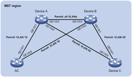
Configuration procedure
1. Configure VLANs:
a. Configure VLANs on Device A:
- Click the system view tab at the bottom of the page.
- From the navigation tree, select Network Configuration > VLAN. You are placed on the VLAN tab.
- Create VLAN 10 and VLAN 30.
- Access the details page for VLAN 10. Add ports GigabitEthernet 1/0/1 and GigabitEthernet 1/0/3 to the tagged port list.
- Access the details page for VLAN 30. Add ports GigabitEthernet 1/0/2 and GigabitEthernet 1/0/3 to the tagged port list.
b. Configure VLANs on Device B:
- Click the system view tab at the bottom of the page.
- From the navigation tree, select Network Configuration > VLAN. You are placed on the VLAN tab.
- Create VLAN 10 and VLAN 30.
- Access the details page for VLAN 10. Add ports GigabitEthernet 1/0/2 and GigabitEthernet 1/0/3 to the tagged port list.
- Access the details page for VLAN 30. Add ports GigabitEthernet 1/0/1 and GigabitEthernet 1/0/3 to the tagged port list.
c. Configure VLANs on the AC:
- Click the system view tab at the bottom of the page.
- From the navigation tree, select Network Configuration > VLAN. You are placed on the VLAN tab.
- Create VLAN 10.
- Access the details page for VLAN 10. Add ports GigabitEthernet 1/0/1 and GigabitEthernet 1/0/2 to the tagged port list.
d. Configure VLANs on Device C:
- Click the system view tab at the bottom of the page.
- From the navigation tree, select Network Configuration > VLAN. You are placed on the VLAN tab.
- Create VLAN 30.
- Access the details page for VLAN 30. Add ports GigabitEthernet 1/0/1 and GigabitEthernet 1/0/2 to the tagged port list.
2. Configure MSTP on Device A, Device B, Device C, and the AC:
a. Click the system view tab at the bottom of the page.
b. From the navigation tree, select Network Configuration > VLAN.
c. Click the STP tab.
d. Enable STP, and configure the operating mode as MSTP.
e. Access the MST region configuration page to perform the following tasks:
- Configure the MST region name as Web.
- Map VLAN 10 and VLAN 30 to MSTI 1 and MSTI 2, respectively.
- Set the MSTP revision level to 0.
Verifying the configuration
# Verify that the port roles and port states in the spanning tree status are as expected.
Outbound dynamic NAT configuration example
Network requirements
As shown in Figure 28, a company has a private address 192.168.0.0/16 and two public IP addresses 202.38.1.2 and 202.38.1.3. Configure outbound dynamic NAT to allow only internal users on subnet 192.168.1.0/24 to access the Internet.
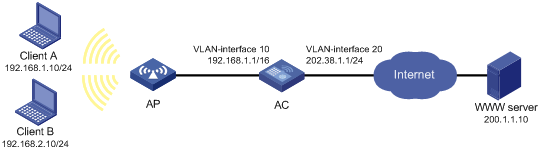
Configuration procedures
1. Click the system view tab at the bottom of the page.
2. From the navigation tree, select Network Configuration > Network Services >NAT.
3. Click Dynamic NAT.
4. Click the add icon.
5. On the New Dynamic NAT Rule page, perform the following tasks:
a. Add ACL 2000 to permit packets only from subnet 192.168.1.0/24 to pass through.
b. Add address group 0, and add an address range from 202.38.1.2 to 202.38.1.3 to the group.
6. Apply the dynamic NAT rule to VLAN-interface 20.
Verifying the configuration
# Verify that Client A can access the WWW server, but Client B cannot. (Details not shown.)
Outbound static NAT configuration example
Network requirements
Configure static NAT to enable the client to access the server on the external network.
Figure 29 Network diagram

Configuration procedures
1. Click the system view tab at the bottom of the page.
2. From the navigation tree, select Network Configuration > Network Services >NAT.
3. Click Static NAT.
4. Click the Rules tab.
5. Click the ![]() icon.
icon.
6. Select the Host to host translation mode.
7. Enter 10.110.10.8 in the private address field and 202.38.1.100 in the public address field.
8. Click Apply.
9. Click the Apply tab.
10. Select interface VLAN-interface 20.
11. Click Apply.
Verifying the configuration
# Verify that the client can access the server on the external network.
NAT Server for external-to-internal access configuration example
Network requirements
As shown in Figure 30, two Web servers, one FTP server and one SMTP server are in the internal network to provide services for external users. The internal network address is 10.110.0.0/16. The company has three public IP addresses from 202.38.1.1/24 to 202.38.1.3/24.
Configure the NAT Server feature to allow the external user to access the internal servers with public address 202.38.1.1/24.
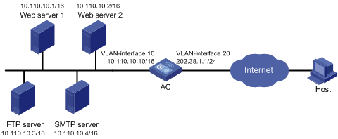
Configuration procedures
1. Click the system view tab at the bottom of the page.
2. From the navigation tree, select Network Configuration > Network Services >NAT.
3. Click NAT Server.
4. Add the following servers:
# FTP server:
a. Click the add icon.
The New NAT Server page opens.
b. Select TCP from the IP protocol list.
c. Select a single public address with a single or no public port from the mapping type list.
d. Select Specify an IP address, set the address to 202.38.1.1, and set the port number to 21.
e. Set the IP address and port number for the internal server to 10.110.10.3 and 21, respectively.
f. Click Apply.
# Web server 1:
a. Click the add icon.
The New NAT Server page opens.
b. Select TCP from the IP protocol list.
c. Select a single public address with a single or no public port from the mapping type list.
d. Select Specify an IP address, set the address to 202.38.1.1, and set the port number to 80.
e. Set the IP address and port number for the internal server to 10.110.10.2 and 80, respectively.
f. Click Apply.
# Web server 2:
a. Click the add icon.
The New NAT Server page opens.
b. Select TCP from the IP protocol list.
c. Select a single public address with a single or no public port from the mapping type list.
d. Select Specify an IP address, set the address to 202.38.1.1, and set the port number to 80.
e. Set the IP address and port number for the internal server to 10.110.10.2 and 80, respectively.
f. Click Apply.
# SMTP server:
a. Click the add icon.
The New NAT Server page opens.
b. Select TCP from the IP protocol list.
c. Select a single public address with a single or no public port from the mapping type list.
d. Select Specify an IP address, set the address to 202.38.1.1, and set the port number to 25.
e. Set the IP address and port number for the internal server to 10.110.10.4 and 25, respectively.
f. Click Apply.
Verifying the configuration
# Verify that the host on the external network can access the internal servers by using the public addresses. (Details not shown.)
Static NAT 444 configuration example
Network requirements
As shown in Figure 31, configure static NAT444 to allow users at private IP addresses 10.110.10.1 to 10.110.10.10 to use public IP address 202.38.1.100 for accessing the Internet. Configure the port range as 10001 to 15000, and set the port block size to 500.
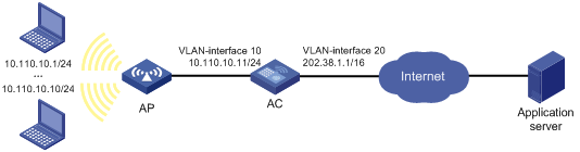
Configuration procedures
1. Click the system view tab at the bottom of the page.
2. From the navigation tree, select Network Configuration > Network Services >NAT.
3. Click Static NAT444.
4. Click the add icon.
The NAT configuration page opens.
5. Click the add icon besides the port block group list.
The New NAT Port Block Group window opens.
6. Set the group ID to 1, port range to 10001 to 15000, and port block size to 500.
7. Add private address range 10.110.10.1 to 10.110.10.10.
8. Add public address range with the start IP address of 202.38.1.100.
9. Click Apply.
10. On the NAT configuration page, select VLAN-interface 20 from the interface list.
11. Select group 1 from the port block group list.
12. Click Apply.
Verifying the configuration
# Verify that the client on the internal network can access the external server. (Details not shown.)
Dynamic NAT 444 configuration example
Network requirements
As shown in Figure 32, a company uses private IP address on network 192.168.0.0/16 and public IP addresses 202.38.1.2 and 202.38.1.3. Configure dynamic NAT444 to meet the following requirements:
· Only users on subnet 192.168.1.0/24 can use public IP addresses 202.38.1.2 and 202.38.1.3 to access the Internet.
· The port range for the public IP addresses is 1024 to 65535.
· The port block size is 300.
· If the ports in the assigned port block are all used, extend another port block for users.
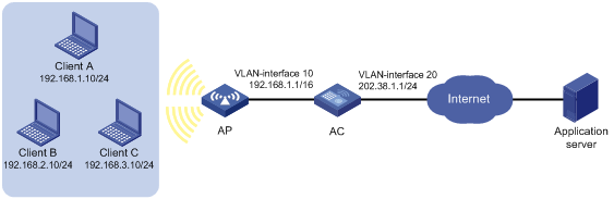
Configuration procedures
1. Click the system view tab at the bottom of the page.
2. From the navigation tree, select Network Configuration > Network Services >NAT.
3. Click Dynamic NAT444.
4. Click the add icon.
The New Outbound Dynamic NAT444 Rule page opens.
5. Click the add icon next to the address group list.
The New NAT444 Address Group window opens.
6. Set the group ID to 0, port range to 1024 to 65535, port block size to 300, and extended port blocks to 1.
7. Add IP address range 202.38.1.2 to 202.38.1.3.
8. Click Apply.
9. On the NAT configuration page, click the add icon.
The New Outbound Dynamic NAT444 Rule page opens.
10. Add IPv4 ACL 2000 to permit packets only from subnet 192.168.1.0/24 to pass through.
11. Select VLAN-interface 20 from the interface list.
12. Select group 0 from the address group list.
13. Click Apply.
Verifying the configuration
# Verify that Client A on the internal network can access the external server, but Client B and Client C cannot. (Details not shown.)
IPv4 static route configuration example
Network requirements
As shown in Figure 33, configure IPv4 static routes on the ACs for the clients to communicate with each other.
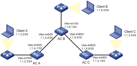
Configuration procedure
1. On AC A, configure a default route:
a. Click the system view tab at the bottom of the page.
b. From the navigation tree, select Network Configuration > Network Routing.
c. Click the Static Routing tab.
d. Click IPv4 static routing.
e. Configure the default route:
- Set the destination IP address to 0.0.0.0.
- Set the mask length to 0.
- Set the next hop address to 1.1.4.2.
2. On AC B, configure static routes to reach Client A and Client C:
a. Click the system view tab at the bottom of the page.
b. From the navigation tree, select Network Configuration > Network Routing.
c. Click the Static Routing tab.
d. Click IPv4 static routing.
e. Configure a static route to the network that contains Client A:
- Set the destination address to 1.1.3.0.
- Set the mask length to 24.
- Set the next hop address to 1.1.5.6.
f. Configure a static route to the network that contains Client C:
- Set the destination address to 1.1.2.0.
- Set the mask length to 24.
- Set the next hop address to 1.1.4.1.
3. On AC C, configure a default route:
a. Click the system view tab at the bottom of the page.
b. From the navigation tree, select Network Configuration > Network Routing.
c. Click the Static Routing tab.
d. Click IPv4 static routing.
e. Configure the default route:
- Set the destination address to 0.0.0.0.
- Set the mask length to 0.
- Set the next hop address to 1.1.5.5.
Verifying the configuration
# Verify that the clients can ping each other. (Details not shown.)
IPv6 static route configuration example
Network requirements
As shown in Figure 34, configure IPv6 static routes on the ACs for the clients to communicate with each other.
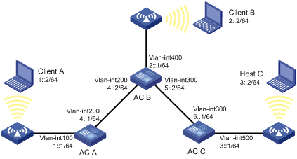
Configuration procedure
1. On AC A, configure an IPv6 default route:
a. Click the system view tab at the bottom of the page.
b. From the navigation tree, select Network Configuration > Network Routing.
c. Click the Static Routing tab.
d. Click IPv6 static routing.
e. Configure the IPv6 default route:
- Set the destination IP address to ::.
- Set the mask length to 0.
- Set the next hop address to 4::2.
2. On AC B, configure IPv6 static routes to reach Client A and Client C:
a. Click the system view tab at the bottom of the page.
b. From the navigation tree, select Network Configuration > Network Routing.
c. Click the Static Routing tab.
d. Click IPv6 static routing.
e. Configure an IPv6 static route to the network that contains Client A:
- Set the destination address to 3::2.
- Set the mask length to 64.
- Set the next hop address to 5::1.
f. Configure an IPv6 static route to the network that contains Client C:
- Set the destination address to 1::2.
- Set the mask length to 64.
- Set the next hop address to 4::1.
3. On AC C, configure an IPv6 default route:
a. Click the system view tab at the bottom of the page.
b. From the navigation tree, select Network Configuration > Network Routing.
c. Click the Static Routing tab.
d. Click IPv6 static routing.
e. Configure the IPv6 default route:
- Set the destination address to ::.
- Set the mask length to 0.
- Set the next hop address to 5::2.
Verifying the configuration
# Verify that the clients can ping each other. (Details not shown.)
Static IPv6 address configuration example
Network requirements
As shown in Figure 35, the client generates an IPv6 address through stateless address autoconfiguration.
Assign a global unicast IPv6 address to VLAN-interface 1 of the AC.
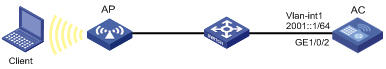
Configuration procedure
1. Configure basic functions on the AC. For more information about the configuration, see WLAN Configuration Guide. (Details not shown.)
2. Configure an IPv6 address for VLAN-interface 1:
a. Click the system view tab at the bottom of the page.
b. From the navigation tree, select Network Configuration > Network Services > IP Services.
c. Click the IPv6 tab.
d. Access the details page for VLAN-interface 1 to perform the following tasks:
- Configure the IPv6 address of the interface as 2001::1.
- Set the prefix length to 64.
3. Configure VLAN-interface 1 to advertise RA messages.
a. Click the system view tab at the bottom of the page.
b. From the navigation tree, select Network Configuration > Network Services > ND. You are placed on the ND tab.
c. Access the advanced settings page to configure the RA settings.
d. Configure VLAN-interface 1 to advertise RA messages.
4. Install IPv6 on the client. The client automatically generates an IPv6 address based on the address prefix information contained in the RA message.
Verifying the configuration
# Verify that the client and the AC can ping each other.
DHCP server configuration example
Network requirements
As shown in Figure 36, the DHCP server (AC) assigns IP addresses to the AP and DHCP clients on subnet 10.1.1.0/24, which is subnetted into 10.1.1.0/25 and 10.1.1.128/25. The AC is connected to the clients and the AP through two VLAN interfaces: VLAN-interface 10 at 10.1.1.1/25 and VLAN-interface 20 at 10.1.1.129/25.
Configure DHCP server on the AC to assign an IP address on subnet 10.1.1.0/25 to the AP and IP addresses on subnet 10.1.1.128/25 to DHCP clients.
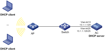
Configuration procedure
1. Click the system view tab at the bottom of the page.
2. Configure VLANs and VLAN interfaces:
a. From the navigation tree, select Network Configuration > VLAN. You are placed on the VLAN tab.
b. Create VLANs and assign IP addresses to VLAN interfaces:
- Create VLAN 10 and assign IP address 10.1.1.1/25 to VLAN-interface 10.
- Create VLAN 20 and assign IP address 10.1.1.129/25 to VLAN-interface 20.
3. Configure the DHCP server:
a. From the navigation tree, select Network Configuration > Network Services > DHCP/DNS. You are placed on the DHCP tab.
b. Enable DHCP.
c. Specify VLAN-interface 10 and VLAN-interface 20 as DHCP servers.
d. Click the address pool link and perform the following tasks:
- Create the address pool pool1, specify 10.1.1.0/25 as the subnet for dynamic assignment, and specify 10.1.1.1 as the gateway.
- Create the address pool pool2, specify 10.1.1.128/25 as the subnet for dynamic assignment, and specify 10.1.1.129 as the gateway.
e. Access the advanced settings page to perform the following tasks:
- Set the maximum number of ping packets to 1.
- Set the ping response timeout time to 500 milliseconds.
4. Click the network view tab at the bottom of the page.
5. Configure a wireless service:
a. From the navigation tree, select Wireless Configuration > Wireless Networks.
b. Add a wireless service:
- Create a wireless service named service.
- Set the SSID to office.
- Specify the default VLAN 20.
- Enable the wireless service.
6. Configure the AP:
a. From the navigation tree, select Wireless Configuration > AP Management. You are placed on the AP tab.
b. Add and configure the AP:
- Set the AP name to AP1, and set the AP model and serial ID.
- Click the edit icon in the operation column for AP 1.
- Click the wireless service setting tab, and bind the wireless service service to the 5 GHz radio of AP 1.
7. Configure the AP radio:
a. From the navigation tree, select Wireless Configuration > AP Management. You are placed on the AP tab.
b. Set the status of the 5 GHz radio of AP 1 to On.
Verifying the configuration
1. Verify that the AP can obtain an IP address on subnet 10.1.1.0/25 and the gateway address from the DHCP server.
2. Verify that the DHCP clients can obtain IP addresses on subnet 10.1.1.128/25 and the gateway address from the DHCP server.
DHCP relay agent configuration example
Network requirements
As shown in Figure 37, the DHCP clients and the DHCP server are in different subnets. The DHCP clients reside in subnet 10.10.1.0/24 and the DHCP server is at 10.1.1.1/24. An AC is deployed between the DHCP clients and the DHCP server. The AC is connected to the network in which the DHCP clients reside through VLAN-interface 10 at 10.10.1.1/24. The AC is connected to the DHCP server through VLAN-interface 20 at 10.1.1.2/24.
Configure the DHCP relay agent on the AC, so the DHCP clients can obtain IP addresses and other configuration parameters from the DHCP server.
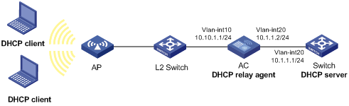
Configuration procedure
1. Assign IP addresses to interfaces. (Details not shown.)
2. Configure the DHCP server. (Details not shown.)
3. Configure basic settings on the AC. (Details not shown.)
4. Configure the DHCP relay agent:
a. Click the system view tab at the bottom of the page.
b. From the navigation tree, select Network Configuration > Network Services > DHCP/DNS. You are placed on the DHCP tab.
c. Perform the following tasks:
- Enable DHCP.
- Specify VLAN-interface 10 as the DHCP relay agent.
- Specify the DHCP server address 10.1.1.1.
Verifying the configuration
Verify that the DHCP clients can obtain IP addresses and other configuration parameters from the DHCP server through the DHCP relay agent.
DHCP snooping configuration example
Network requirements
As shown in Figure 38, the AC is connected to a DHCP server through GigabitEthernet 1/0/1 and to an AP through GigabitEthernet 1/0/2. Configure DHCP snooping on the AC to meet the following requirements:
· Allow only the interface connected to the authorized DHCP server to forward packets from the DHCP server.
· Record the clients' IP-to-MAC binding information in DHCP-REQUEST packets and in DHCP-ACK packets received by trusted ports.
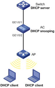
Configuration procedure
1. Configure the DHCP server. (Details not shown.)
2. Configure basic settings on the AC. (Details not shown.)
3. Configure the DHCP snooping device:
a. Click the system view tab at the bottom of the page.
b. From the navigation tree, select Network Configuration > Network Services > DHCP/DNS.
c. Click the DHCP Snooping tab.
d. Perform the following tasks:
- Enable DHCP snooping.
- Configure GigabitEthernet 1/0/1, the interface connected to the authorized DHCP server, as the trusted port.
- Configure GigabitEthernet 1/0/2, the interface connected to the DHCP clients, to record DHCP snooping entries.
Verifying the configuration
# Verify that the AC maintains DHCP snooping entries for clients that have obtained IP addresses through DHCP.
IPv4 static DNS configuration example
Network requirements
As shown in Figure 39, configure a static DNS entry on the AC, so the AC can use the domain name host.com to access the host at 10.1.1.2.
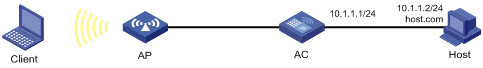
Configuration procedure
1. Click the system view tab at the bottom of the page.
2. From the navigation tree, select Network Configuration > Network Services > DHCP/DNS.
3. Click the IPv4 DNS tab.
4. Create a static DNS entry:
¡ Configure the host name as host.com.
¡ Configure the IPv4 address as 10.1.1.2.
Verifying the configuration
Use the ping host.com command on the AC to verify the following items:
· The ping operation succeeds.
· The AC can use static domain name resolution to resolve the domain name host.com into the IPv4 address 10.1.1.2.
IPv4 dynamic DNS configuration example
Network requirements
As shown in Figure 40, the DNS server at 2.1.1.2/16 has a com domain that stores the mapping between the domain name host and the IPv4 address 3.1.1.1/16.
Configure dynamic DNS and the DNS suffix com on the AC that acts as a DNS client. The AC can use the domain name host to access the host whose domain name is host.com and IPv4 address is 3.1.1.1/16.
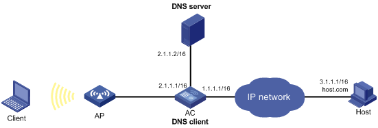
Configuration procedure
1. Map the domain name host.com to the IPv4 address 3.1.1.1 on the DNS server. (Details not shown.)
2. Configure static routes or dynamic routing protocols on the devices to make sure the devices can reach each other. (Details not shown.)
3. Configure DNS client on the AC:
a. Click the system view tab at the bottom of the page.
b. From the navigation tree, select Network Configuration > Network Services > DHCP/DNS.
c. Click the IPv4 DNS tab.
d. Specify the DNS server address 2.1.1.2.
e. Access the advanced settings page and add the domain name suffix com.
Verifying the configuration
Use the ping host command on the AC to verify the following items:
· The ping operation succeeds.
· The AC can resolve the domain name host.com into the IPv4 address 3.1.1.1 through the DNS server.
IPv4 DNS proxy configuration example
Network requirements
As shown in Figure 41, the LAN has a large number of devices deployed. The devices access the DNS server for domain name resolution. If the DNS server's IP address changes, the administrator must modify the DNS server address on each device, which takes a lot of time.
To simplify the configuration, configure the AC as the DNS proxy. Specify the real DNS server address on the AC. Specify the DNS proxy address as the DNS server address on the other devices. If the DNS server address changes, the administrator only needs to modify the DNS server address on the DNS proxy.
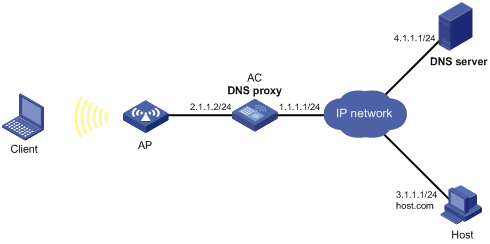
Configuration procedure
1. Configure static routes or dynamic routing protocols on the devices to make sure the devices can reach each other. (Details not shown.)
2. Configure the DNS server. (Details not shown.)
3. Configure DNS proxy on the AC:
a. Click the system view tab at the bottom of the page.
b. From the navigation tree, select Network Configuration > Network Services > DHCP/DNS.
c. Click the IPv4 DNS tab.
d. Specify the DNS server address 4.1.1.1.
e. On the advanced settings page, enable DNS proxy.
4. Configure DNS clients.
Specify the DNS proxy address 2.1.1.2 as the DNS server address on the other devices that act as DNS clients.
Verifying the configuration
Use the ping host.com command on a DNS client to verify the following items:
· The ping operation succeeds.
· The client can resolve the domain name host.com into the IPv4 address 3.1.1.1 through the DNS server.
IPv6 static DNS configuration example
Network requirements
As shown in Figure 42, configure a static DNS entry on the AC, so the AC can use the domain name host.com to access the host at 1::2.
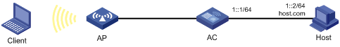
Configuration procedure
1. Click the system view tab at the bottom of the page.
2. From the navigation tree, select Network Configuration > Network Services > DHCP/DNS.
3. Click the IPv6 DNS tab.
4. Create a static DNS entry:
¡ Configure the host name as host.com.
¡ Configure the IPv6 address as 1::2.
Verifying the configuration
Use the ping ipv6 host.com command on the AC to verify the following items:
· The ping operation succeeds.
· The AC can use static domain name resolution to resolve the domain name host.com into the IPv6 address 1::2.
IPv6 dynamic DNS configuration example
Network requirements
As shown in Figure 43, the DNS server at 2::2/64 has a com domain that stores the mapping between the domain name host and the IPv6 address 1::1/64.
Configure dynamic DNS and the DNS suffix com on the AC that acts as a DNS client. The AC can use the domain name host to access the host whose domain name is host.com and IPv6 address is 1::1/64.
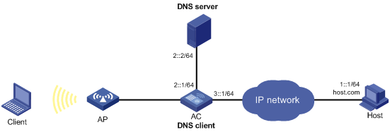
Configuration procedure
1. Map the domain name host.com to the IPv6 address 1::1 on the DNS server. (Details not shown.)
2. Configure static routes or dynamic routing protocols on the devices to make sure the devices can reach each other. (Details not shown.)
3. Configure DNS client on the AC:
a. Click the system view tab at the bottom of the page.
b. From the navigation tree, select Network Configuration > Network Services > DHCP/DNS.
c. Click the IPv6 DNS tab.
d. Specify the DNS server address 2::2.
e. Access the advanced settings page and add the domain name suffix com.
Verifying the configuration
Use the ping ipv6 host command on the AC to verify the following items:
· The ping operation succeeds.
· The AC can resolve the domain name host.com into the IPv6 address 1::1 through the DNS server.
IPv6 DNS proxy configuration example
Network requirements
As shown in Figure 44, the LAN has a large number of devices deployed. The devices access the DNS server for domain name resolution. If the DNS server's IPv6 address changes, the administrator must modify the DNS server address on each device, which takes a lot of time.
To simplify the configuration, configure the AC as the DNS proxy. Specify the real DNS server address on the AC. Specify the DNS proxy address as the DNS server address on the other devices. If the DNS server address changes, the administrator only needs to modify the DNS server address on the DNS proxy.
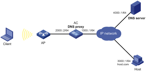
Configuration procedure
1. Configure static routes or dynamic routing protocols on the devices to make sure the devices can reach each other. (Details not shown.)
2. Configure the DNS server. (Details not shown.)
3. Configure DNS proxy on the AC:
a. Click the system view tab at the bottom of the page.
b. From the navigation tree, select Network Configuration > Network Services > DHCP/DNS.
c. Click the IPv6 DNS tab.
d. Specify the DNS server address 4000::1.
e. On the advanced settings page, enable DNS proxy.
4. Configure DNS clients.
Specify the DNS proxy address 2000::2 as the DNS server address on the other devices that act as DNS clients.
Verifying the configuration
Use the ping ipv6 host.com command on a DNS client to verify the following items:
· The ping operation succeeds.
· The client can resolve the domain name host.com into the IPv6 address 3000::1 through the DNS server.
IGMP snooping configuration example
Network requirements
As shown in Figure 45:
· The network is a Layer 2-only network.
· Source 1 sends multicast data to the multicast group 224.1.1.1, and Host A and Host B are receivers of the group.
· Host A and Host B run IGMPv2. The AC, Switch A, and Switch B run IGMPv2 snooping, and the AC acts as the IGMP querier.
Configure the devices to meet the following requirements:
· For IGMP snooping forwarding entries to be created, configure the source IP address of IGMP queries as a non-zero IP address on the AC.
· To prevent unknown multicast data from being flooded in VLAN 1, enable the devices to drop unknown multicast data.
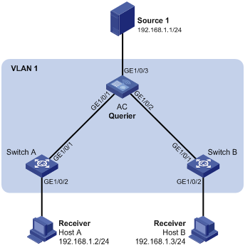
Configuration procedure
1. Configure the AC:
a. Click the system view tab at the bottom of the page.
b. From the navigation tree, select Network Configuration > Network Services > Multicast. You are placed on the IGMP Snooping tab.
c. Enable IGMP snooping.
d. Access the page for enabling IGMP snooping on a VLAN to perform the following tasks:
- Set the VLAN ID to 1.
- Set the IGMP snooping version to 2.
- Enable dropping unknown multicast data.
- Enable the AC to act as the IGMP querier.
- Set the source IP address to 192.168.1.10 for IGMP general queries.
- Set the source IP address to 192.168.1.10 for IGMP group-specific queries.
2. Configure Switch A:
# Enable IGMP snooping for VLAN 1, set the IGMP snooping version to 2, and then enable dropping unknown multicast data. (Details not shown.)
3. Configure Switch B in the same way Switch A is configured. (Details not shown.)
Verifying the configuration
1. Send IGMP reports from Host A and Host B to join the multicast group 224.1.1.1. (Details not shown.)
2. Send multicast data from the source to the multicast group. (Details not shown.)
3. Access the Network Configuration> Network Services > Multicast > IGMP snooping > Entries page to verify that GigabitEthernet 1/0/1 and GigabitEthernet 1/0/2 are host ports of VLAN 1.
MLD snooping configuration example
Network requirements
As shown in Figure 46:
· The network is a Layer 2-only network.
· Source 1 sends IPv6 multicast data to the IPv6 multicast group FF1E::101. Host A and Host B are receivers of the group.
· Host A and Host B run MLDv1. The AC, Switch A, and Switch B run MLDv1 snooping, and the AC acts as the MLD querier.
To prevent unknown IPv6 multicast data from being flooded in VLAN 1, enable all the devices to drop unknown IPv6 multicast data.
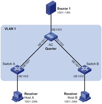
Configuration procedure
1. Configure the AC:
a. Click the system view tab at the bottom of the page.
b. From the navigation tree, select Network Configuration > Network Services > Multicast. You are placed on the IGMP Snooping tab.
c. Click the MLD Snooping tab, and then enable MLD snooping.
d. Access the page for enabling MLD snooping on a VLAN to perform the following tasks:
- Set the VLAN ID to 1.
- Set the MLD snooping version to 1.
- Enable dropping unknown IPv6 multicast data.
- Enable the AC to act as an MLD querier.
- Apply the configuration.
2. Configure Switch A:
# Enable MLD snooping for VLAN 1, set the MLD snooping version to 1, and then enable dropping unknown IPv6 multicast data. (Details not shown.)
3. Configure Switch B in the same way Switch A is configured. (Details not shown.)
Verifying the configuration
1. Send MLD reports from Host A and Host B to join the IPv6 multicast group FF1E::101. (Details not shown.)
2. Send IPv6 multicast data from Source 1 to the IPv6 multicast group. (Details not shown.)
3. Access the Network Configuration> Network Services > Multicast > MLD snooping > Entries page to verify that GigabitEthernet 1/0/1 and GigabitEthernet 1/0/2 are host ports of VLAN 1.
Proxy ARP configuration example
Network requirements
As shown in Figure 47, Client 1 and Client 2 have the same IP prefix and mask, but they are located on different subnets separated by the AC. Client 1 belongs to VLAN 10, and Client 2 belongs to VLAN 20. No default gateway is configured on Client 1 and Client 2.
Configure proxy ARP on the AC to enable communication between the two clients.
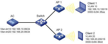
Configuration procedure
1. Configure VLAN 10 and VLAN 20, and assign IP addresses to VLAN-interface 10 and VLAN-interface 20:
a. Click the system view tab at the bottom of the page.
b. From the navigation tree, select Network Configuration > VLAN. You are placed on the VLAN tab.
c. Create VLAN 10, and assign IP address 192.168.10.99/24 to VLAN-interface 10.
d. Create VLAN 20, and assign IP address 192.168.20.99/24 to VLAN-interface 20.
2. Enable proxy ARP on VLAN-interface 10 and VLAN-interface 20.
a. Click the system view tab at the bottom of the page.
b. From the navigation tree, select Network Configuration > Network Services > ARP. You are placed on the ARP tab.
c. Access the advanced settings page to configure proxy ARP.
- Enable proxy ARP on VLAN-interface 10.
- Enable proxy ARP on VLAN-interface 20.
Verifying the configuration
# Verify that Client 1 and Client 2 can ping each other.
ARP attack protection configuration example
Network requirements
As shown in Figure 48, Client 1 obtains an IP address from the switch (DHCP server). Client 2 is manually assigned IP address 10.1.1.6.
Configure the AC to perform ARP packet validity check and user validity check for connected clients.
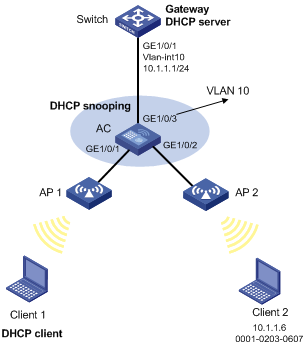
Configuration procedure
1. Assign all interfaces to VLAN 10, and specify the IP address of VLAN-interface 10 on the switch. (Details not shown.)
2. Configure the DHCP server on the switch. (Details not shown.)
3. Configure Client 1 (the DHCP client) and Client 2. (Details not shown.)
4. Enable DHCP snooping on the AC:
a. Click the system view tab at the bottom of the page.
b. From the navigation tree, select Network Configuration > Network Services > DHCP/DNS.
c. Click the DHCP Snooping tab.
d. Enable DHCP snooping.
e. Configure GigabitEthernet 1/0/3 as a trusted port.
f. Enable recording of client information in DHCP snooping entries on GigabitEthernet 1/0/1.
5. Configure ARP detection on the AC:
a. Click the system view tab at the bottom of the page.
b. From the navigation tree, select Network Configuration > Network Services > ARP. You are placed on the ARP tab.
c. Access the advanced settings page to configure ARP detection under ARP attack protection.
d. Enable ARP detection for VLAN 10.
e. Access the advanced settings page for ARP detection to perform the following tasks:
- Configure GigabitEthernet 1/0/3 as a trusted interface.
By default, an interface is an untrusted interface.
- Enable ARP packet validity check by checking the sender MAC address, target MAC address, and IP addresses of ARP packets.
After the configurations are completed, the AC first checks the validity of ARP packets received on GigabitEthernet 1/0/1 and GigabitEthernet 1/0/2. If the ARP packets are confirmed valid, the switch performs user validity check by using the DHCP snooping entries.
Verifying the configuration
# Access the ARP page to verify that ARP entry for Client 1 is created and no ARP entry is created for Client 2.
Using the device as the Stelnet server for password authentication configuration example
Network requirements
As shown in Figure 49:
· The device acts as the Stelnet server and uses password authentication.
· The username and password of the client are saved on the device.
Establish an Stelnet connection between the host and the device, so you can log in to the device to configure and manage the device.
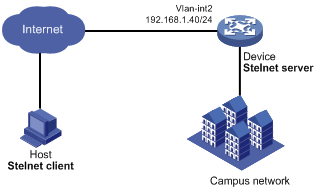
Configuration procedure
1. Configure the Stelnet server:
a. Click the system view tab at the bottom of the page.
b. From the navigation tree, select Network Configuration > Management Protocols.
c. Click the SSH tab.
d. Enable the Stelnet service.
2. Configure the VLAN interface:
a. Click the system view tab at the bottom of the page.
b. From the navigation tree, select Network Configuration > VLAN.
c. On the VLAN tab, create VLAN 2.
d. Click the edit icon for VLAN 2.
The Edit VLAN page opens.
e. Add GigabitEthernet 1/0/2 to the untagged port list.
f. Select Configure VLAN interface.
g. Set the IPv4 address/mask to 192.168.1.40/24.
3. Configure the administrator account:
a. Click the system view tab at the bottom of the page.
b. From the navigation tree, select System > Administrators.
c. Click the add icon.
d. Set the username and password to client and aabbcc, respectively.
e. Select network-admin from the user roles list.
f. Select SSH for the permitted access types parameter.
Verifying the configuration
This example uses PuTTY0.58 to verify the configuration.
1. Execute PuTTY.
2. Enter 192.168.1.40 in the Host Name (or IP address) field.
3. Click Open.
4. Verify that you can use username client and password aabbcc to log in to the configuration page of the device.
NTP configuration example
Network requirements
As shown in Figure 50:
· Configure the local clock of Device A as a reference source, with the stratum level 2.
· Set Device B to client mode and use Device A as the NTP server for Device B.
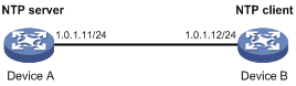
Configuration procedure
1. Configure Device A (NTP server):
a. Click the system view tab at the bottom of the page.
b. From the navigation tree, select Network Configuration > Management Protocols.
c. Click the NTP tab.
d. Enable the NTP service.
e. Specify the IP address of the local clock as 127.127.1.0.
f. Configure the stratum level of the local clock as 2.
2. Configure Device B:
a. Click the system view tab at the bottom of the page.
b. From the navigation tree, select System > Management. You are placed on the Settings tab.
c. Select automatic time synchronization with a trusted time source, and then select NTP as the time protocol.
d. Specify the IP address of Device A as 1.0.1.11, and configure Device B to operate in server mode.
Verifying the configuration
# Verify that Device B has synchronized to Device A, and the clock stratum level is 3 on Device B and 2 on Device A.
LLDP configuration example
Network requirements
As shown in Figure 51, configure LLDP on the AC and switch to meet the following requirements:
· The AC can discover the switch and obtain system and configuration information from the switch.
· The switch cannot discover the AC.
Configuration procedure
1. Configure LLDP on the AC:
a. Click the system view tab at the bottom of the page.
b. From the navigation tree, select Network Configuration > Management Protocols.
c. Click the LLDP tab.
d. Enable LLDP globally.
e. Access the interface status page, and then enable LLDP on GigabitEthernet 1/0/1.
f. Access the interface configuration page to perform the following tasks:
- Enable the nearest bridge agent function on GigabitEthernet 1/0/1.
- Set the operating mode of the interface to Rx mode to configure the interface to only receive LLDP frames.
Then, the AC can discover neighbors.
2. Configure LLDP on the switch:
a. Click the system view tab at the bottom of the page.
b. From the navigation tree, select Network Configuration > Management Protocols > LLDP.
c. Enable LLDP globally on the switch.
d. Access the interface status page, and then enable LLDP on GigabitEthernet 1/0/2.
e. Access interface configuration page to perform the following tasks:
- Enable the nearest bridge agent function on GigabitEthernet 1/0/2.
- Set the operating mode of the interface to Tx mode to configure the interface to only transmit LLDP frames.
Then, the switch cannot discover neighbors.
Verifying the configuration
1. Verify that you can view information about the switch on the LLDP neighbor information page of the AC.
2. Verify that the LLDP neighbor information page of the switch does not contain an entry for the AC.
Network security configuration examples
ACL-based packet filter configuration example
Network requirements
As shown in Figure 52, a company interconnects its departments through the AC. Configure the packet filter on the AC to meet the following requirements:
· Permit access from the President's office at any time to the financial database server.
· Permit access from the Financial Department to the financial database server only during working hours (from 8:00 to 18:00) on working days.
· Deny access from any other department to the financial database server.
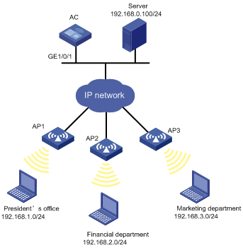
Configuration procedure
1. Click the system view tab at the bottom of the page.
2. From the navigation tree, select Network Security > Packet Filter.
3. Create a packet filter policy:
a. Select VLAN-interface 10.
b. Select the outbound application direction.
c. Select the IPv4 ACL type for packet filter.
4. Create an advanced IPv4 ACL and configure the following rules in the order they are described:
|
Action |
Protocol type |
IP/wildcard mask |
Time range |
|
Permit |
256 |
Source: 192.168.1.0/0.0.0.255 Destination: 192.168.0.100/0 |
N/A |
|
Permit |
256 |
Source: 192.168.2.0/0.0.0.255 Destination: 192.168.0.100/0 |
Create a time range named work: · Specify the start time as 08:00. · Specify the end time as 18:00. · Select Monday through Friday. |
|
Deny |
256 |
Destination: 192.168.0.100/0 |
N/A |
5. Enable rule match counting for the ACL.
Verifying the configuration
1. Ping the database server from different departments to verify the following items:
¡ You can access the server from the President's office at any time.
¡ You can access the server from the Financial Department during the working hours on working days.
¡ You cannot access the server from the Marketing Department at any time.
2. Access the ACL rule Web interface, verify that the ACL rules are active and the number of matching packets is displayed.
QoS configuration example
Network requirements
As shown in Figure 53, configure QoS for the device, so the device forwards packets from different departments in the following order when congestion occurs:
· Administration department.
· R&D department.
· Marketing department.
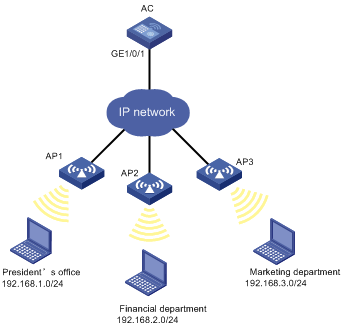
Configuration procedure
1. Configure QoS policies:
a. Click the system view tab at the bottom of the page.
b. From the navigation tree, select Network Security > Traffic Policy.
c. Click the QoS Policies tab.
d. Apply a QoS policy to the incoming traffic of GigabitEthernet 1/0/2.
e. Modify the applied QoS policy as follows:
- Create IPv4 ACL 2000, and add a rule to permit packets with source IP address 192.168.1.0 and mask 0.0.0.255.
- Configure the ACL as a match criterion of a class, and specify the associated behavior to mark the matched packets with 802.1p priority 2.
f. Apply a QoS policy to the incoming traffic of GigabitEthernet 1/0/3.
g. Modify the applied QoS policy as follows:
- Create IPv4 ACL 2002, and add a rule to permit packets with source IP address 192.168.2.0 and mask 0.0.0.255.
- Configure the ACL as a match criterion of a class, and specify the associated behavior to mark the matched packets with 802.1p priority 0.
h. Apply a QoS policy to the incoming traffic of GigabitEthernet 1/0/4.
i. Modify the applied QoS policy as follows:
- Create IPv4 ACL 2003, and add a rule to permit packets with source IP address 192.168.1.0 and mask 0.0.0.255.
- Configure the ACL as a match criterion of a class, and specify the associated behavior to mark the matched packets with 802.1p priority 1.
2. Configure priority mapping:
a. Click the system view tab at the bottom of the page.
b. From the navigation tree, select Network Security > Traffic Policy.
c. Click the Priority Mapping tab.
d. Click Port Priority.
e. Configure GigabitEthernet 1/0/1, GigabitEthernet 1/0/2, GigabitEthernet 1/0/3, and GigabitEthernet 1/0/4 to trust the 802.1p priority.
f. Click Apply.
g. On the Priority Mapping tab, click Priority Map-table.
h. Configure the 802.1p-to-local priority mapping table to map 802.1p priority values 0, 1, and 2 to local precedence values 0, 1, and 2, respectively.
Verifying the configuration
On the QoS policy page, verify that the QoS policies are applied correctly. (Details not shown.)
System configuration examples
Administrators configuration example
Network requirements
As shown in Figure 54, configure an administrator account with the username webuser and password 12345 on the AC to meet the following requirements:
· Allow the user to use the account to log in to the AC through HTTP.
· Perform local authentication for the user that uses the administrator account to log in to the AC.
· Assign the network-admin user role to the authenticated user.
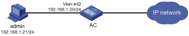
Configuration procedure
1. Click the system view tab at the bottom of the page.
2. Configure the VLAN and VLAN interface:
a. From the navigation tree, select Network Configuration > VLAN. You are placed on the VLAN tab.
b. Create VLAN 2.
c. Access the edit page for VLAN 2 to perform the following tasks:
- Add the interface that connects to the admin's PC to the tagged port list.
- Create VLAN-interface 2.
- Assign the IP address 192.168.1.20/24 to VLAN-interface 2.
3. Configure an administrator account:
a. From the navigation tree, select System > Administrators. You are placed on the Administrators tab.
b. Create and configure an administrator account:
- Set the username and the password to webuser and 12345, respectively.
- Select the network-admin user role.
- Specify HTTP and HTTPS as the permitted access types.
Verifying the configuration
1. Access the System > Administrators page to verify that the administrator account is successfully added.
2. Enter http://192.168.1.20 in the address bar to verify the following items:
¡ You can use the administrator account to log in to the Web interface.
¡ After login, you can configure the device.
Network configuration examples
Wireless configuration examples
CAPWAP tunnel establishment through DHCP configuration example
Network requirements
As shown in Figure 55, configure the AP to obtain its IP address and the AC's IP address from the DHCP server (the AC) through DHCP Option 43. The AP uses the IP address of the AC to establish a CAPWAP tunnel with the AC.
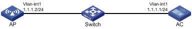
Configuration procedure
1. Click the system view tab at the bottom of the page.
2. Set the AC IP address:
a. From the navigation tree, select Network Configuration > VLAN. You are placed on the VLAN tab.
b. Click the edit icon in the operation column for VLAN-interface 1.
c. Set the IP address to 1.1.1.1/24.
3. Configure DHCP:
a. From the navigation tree, select Network Configuration > Network Services > DHCP/DNS. You are placed on the DHCP tab.
b. Enable the DHCP service.
c. Access the DHCP configuration page to select DHCP server from the DHCP service list for VLAN-interface 1.
d. Access the address pool configuration page. You are placed on the Assigned Address tab.
e. Perform the following tasks:
- Create an address pool named pool1.
- Specify subnet 1.1.1.0/24 for dynamic IP address assignment.
f. Click the DHCP Options tab.
g. Perform the following tasks:
- Set the gateway address to 1.1.1.1.
- Configure the content of Option 43 as 800700000101010101.
4. Click the network view tab at the bottom of the page.
5. Configure the AP:
a. From the navigation tree, select Wireless Configuration > AP Management. You are placed on the AP tab.
b. Add and configure AP 1:
- Set the AP name to AP1.
- Set the AP model and serial ID.
Verifying the configuration
# Access the Wireless Configuration > AP Management > AP page to verify that AP 1 has come online.
# Access the AP details page to verify the following information:
· The AP has obtained an IP address.
· The AC IP address is 1.1.1.1/24.
· The AC discovery type is DHCP.
CAPWAP tunnel establishment through DNS configuration example
Network requirements
As shown in Figure 56, configure the AP to obtain the IP address of the AC through DNS to establish a CAPWAP tunnel with the AC.
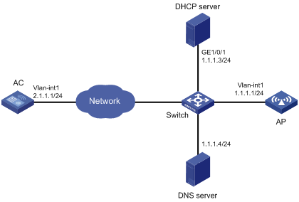
Configuration procedure
1. On the DHCP server, specify subnet 1.1.1.0/24 for IP address assignment, and set the domain name suffix of the AC to abc. (Details not shown.)
2. On the DNS server, configure a mapping between domain name host.abc and IP address 1.1.1.1/24. (Details not shown.)
3. Click the system view tab at the bottom of the page.
4. Set the AC's IP address:
a. From the navigation tree, select Network Configuration > VLAN. You are placed on the VLAN tab.
b. Click the edit icon in the operation column for VLAN-interface 1.
c. Set the IP address to 1.1.1.1/24.
5. Click the network view tab at the bottom of the page.
6. Configure the AP:
a. From the navigation tree, select Wireless Configuration > AP Management. You are placed on the AP tab.
b. Add and configure AP 1:
- Set the AP name to AP1.
- Set the AP model and serial ID.
Verifying the configuration
# Access the Wireless Configuration > AP Management > AP page to verify that AP 1 has come online.
# Access the AP details page to verify the following information:
· The AP has obtained an IP address.
· The AC IP address is 1.1.1.1/24.
· The AC discovery type is DNS.
Auto AP configuration example
Network requirements
As shown in Figure 57, enable the auto AP feature on the AC. The AP obtains the AC's IP address through DHCP Option 43 and establishes a CAPWAP tunnel with the AC.
Configuration procedure
1. Click the system view tab at the bottom of the page.
2. Set the AC IP address:
a. From the navigation tree, select Network Configuration > VLAN. You are placed on the VLAN tab.
b. Click the edit icon in the operation column for VLAN-interface 1.
c. Set the IP address to 1.1.1.1/24.
3. Configure DHCP:
a. From the navigation tree, select Network Configuration > Network Services > DHCP/DNS. You are placed on the DHCP tab.
b. Enable the DHCP service.
c. Access the DHCP configuration page to select DHCP server from the DHCP service list for VLAN-interface 1.
d. Access the address pool configuration page. You are placed on the Assigned Address tab.
e. Perform the following tasks:
- Create an address pool named pool1.
- Specify subnet 1.1.1.0/24 for dynamic IP address assignment.
f. Click the DHCP Options tab.
g. Perform the following tasks:
- Set the gateway address to 1.1.1.1.
- Configure the content of Option 43 as 800700000101010101.
4. Click the network view tab at the bottom of the page.
5. Configure the AP:
a. From the navigation tree, select Wireless Configuration > AP Management.
b. Click the AP Global Settings tab.
c. Enable the auto AP feature.
Verifying the configuration
# Access the Wireless Configuration > AP Management > AP page to verify that AP 1 has come online as an auto AP.
AP group configuration example
Network requirements
As shown in Figure 58, configure AP groups and add AP 1 to the AP group group1, and AP 2, AP 3, and AP 4 to the AP group group2.
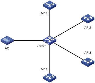
Configuration procedure
1. Configure APs to obtain their IP addresses and the AC's IP address from the DHCP server. (Details not shown.)
2. Click the network view tab at the bottom of the page.
3. Configure the AP groups:
a. From the navigation tree, select Wireless Configuration > AP Management.
b. Click the AP Groups tab.
c. Add two AP groups named group1 and group2.
d. Add the AP ap1 to the AP group group1.
e. Add the APs ap2, ap3, and ap4 to the AP group group2.
Verifying the configuration
# Access the AP groups page to verify the following information:
· The AP ap1 is in the AP list of the AP group group1.
· The APs ap 2, ap 3, and ap 4 are in the AP list of the AP group group2.
Radio management configuration example
Network requirements
As shown in Figure 59, perform the following tasks to configure the 5 GHz radio of the AP:
· Set the radio type, working channel, and maximum transmit power to 802.11ac, 48, and 19 dBm, respectively.
· Set the maximum mandatory NSS, maximum supported NSS, multicast NSS, and VHT-MCS index to 2, 3, 2, and 5, respectively.
· Enable the A-MSDU and A-MPDU aggregation methods to improve network throughput.
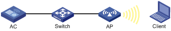
Configuration procedure
1. Click the network view tab at the bottom of the page.
2. From the navigation tree, select Wireless Configuration > Radio Management. You are placed on the Radio Configuration tab.
3. Access the details page for all AP radio configurations.
4. Click the edit icon in the operation column for the 5 GHz radio of the AP. You are placed on the Basic tab.
5. Perform the following tasks in the basic configuration area:
a. Enable the radio.
b. Set the radio type to 802.11ac (5GHz).
c. Set the channel to 48.
d. Set the maximum transmit power to 19 dBm.
6. Perform the following tasks in the rates configuration area:
a. Set the maximum mandatory NSS to 2.
b. Set the maximum supported NSS to 3.
c. Set the multicast NSS to 2.
d. Set the VHT-MCS index to 5.
7. Perform the following tasks in the 802.11n/802.11ac configuration area:
a. Enable the A-MSDU aggregation method.
b. Enable the A-MPDU aggregation method.
8. Apply the configuration.
Verifying the configuration
# Access the Wireless Configuration > Radio Management > Radio Configuration page to verify that the configuration is correct.
WIPS device classification and countermeasures configuration example
Network requirements
As shown in Figure 60, the sensor connects to the AC through the switch. AP 1 and AP 2 provide wireless services to clients through the SSID abc. Perform the following tasks:
· Enable WIPS for the sensor.
· Configure wireless device classification to add the MAC address 000f-1c35-12a5 to the static prohibited device list and the SSID abc to the trusted SSID list.
· Configure countermeasures to enable WIPS to take countermeasures against potential-external APs and unauthorized clients.
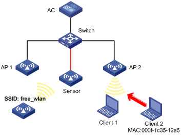
Configuration procedure
1. Click the network view tab at the bottom of the page.
2. Create a manual AP:
a. From the navigation tree, select Wireless Configuration > AP Management. You are placed on the AP tab.
b. Access the page for adding an AP to perform the following tasks:
- Set the AP name to Sensor.
- Specify the AP model and serial ID.
3. Configure WIPS:
a. From the navigation tree, select Wireless Configuration > Wireless Security. You are placed on the WIPS tab.
b. Access the details page for virtual security domain configuration to create the VSD VSD_1.
c. Access the details page for enabling WIPS to enable WIPS for the AP Sensor and add the AP to the VSD VSD_1.
d. Access the details page for classification policy configuration to perform the following tasks:
- Create the classification policy class1.
- Add the MAC address of Client 2 to the prohibited device list.
- Add the SSID abc to the trusted SSID list.
e. Access the details page for countermeasure policy configuration to perform the following tasks:
- Create the countermeasure policy protect.
- Configure WIPS to take countermeasures against unauthorized clients and potential-external APs.
f. Access the modifying VSD page for the VSD VSD_1 to perform the following tasks:
- Apply the classification policy class1 to the VSD VSD_1.
- Apply the countermeasure policy protect to the VSD VSD_1.
Verifying the configuration
# Verify that the AP with the MAC address 000f-e223-1616 is classified as a potential-external AP and the client with the MAC address 000f-1c35-12a5 is classified as an unauthorized client.
# Verify that WIPS has taken countermeasures against the unauthorized client with the MAC address 000f-1c35-12a5 and the potential-external AP with the MAC address 000f-e223-1616.
WIPS malformed packet and flood attack detection configuration example
Network requirements
As shown in Figure 61, configure the two APs that connect to the AC through the switch as sensors. Add Sensor 1 and Sensor 2 to the VSD VSD_1. Configure malformed packet detection and flood attack detection to enable WIPS to trigger an alarm when it detects beacon flood attacks or malformed packets with duplicated IE.
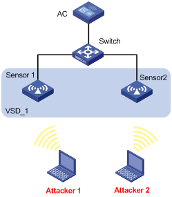
Configuration procedure
1. Click the network view tab at the bottom of the page.
2. Create a manual AP:
a. From the navigation tree, select Wireless Configuration > AP Management. You are placed on the AP tab.
b. Create two APs named Sensor 1 and Sensor 2.
c. Specify the AP model and serial ID for the APs.
3. Configure WIPS:
a. From the navigation tree, select Wireless Configuration > Wireless Security. You are placed on the WIPS tab.
b. Access the details page for virtual security domain configuration to create the VSD VSD_1.
c. Access the details page for enabling WIPS to enable WIPS for the APs Sensor 1 and Sensor 2 and add the APs to the VSD VSD_1.
d. Access the page for adding an attack detection policy to perform the following tasks:
- Create an attack detection policy.
- Enable detection on malformed packets with duplicated IE, and set the quiet time to 50 seconds.
- Enable beacon flood attack detection, and set the statistics interval, threshold, and quiet time to 100 seconds, 200, and 50 seconds, respectively.
e. Access the modifying page for the VSD VSD_1 to apply the attack detection policy to the VSD VSD_1.
Verifying the configuration
# Verify that no malformed packets or flood attack messages exist when WIPS does not detect any attacks in the WLAN.
# Verify that the number of malformed packets or flood attack messages is not zero when WIPS detects beacon flood attacks and malformed packets with duplicated IE.
Signature-based attack detection configuration example
Network requirements
As shown in Figure 62, AP 1 and AP 2 provide wireless services for clients through the SSID abc. Enable WIPS for the sensor, and configure a signature to enable WIPS to trigger an alarm when it detects beacon frames whose SSIDs are not abc.
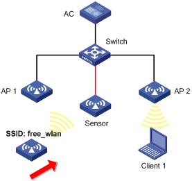
Configuration procedure
1. Click the network view tab at the bottom of the page.
2. Create a manual AP:
a. From the navigation tree, select Wireless Configuration > AP Management. You are placed on the AP tab.
b. Access the page for adding an AP to perform the following tasks:
- Set the AP name to Sensor.
- Specify the AP model and serial ID for the APs.
3. Configure WIPS:
a. From the navigation tree, select Wireless Configuration > Wireless Security. You are placed on the WIPS tab.
b. Access the details page for virtual security domain configuration to create the VSD vsd1.
c. Access the details page for enabling WIPS to enable WIPS for the AP Sensor and add the AP to the VSD vsd1.
d. Access the details page for signature rule configuration to perform the following tasks:
- Create signature 1.
- Configure a subsignature to match beacon frames.
- Configure a subsignature to match frames whose SSIDs are not abc.
e. Access the details page for signature policy configuration to perform the following tasks:
- Create a signature policy named sig1.
- Bind signature 1 to the signature policy sig1.
- Set the statistics collection interval, quiet time, and alarm threshold to 5 seconds, 60 seconds, and 60, respectively.
f. Access the modifying page for the VSD vsd1 to apply the signature policy sig1 to the VSD vsd1.
Verifying the configuration
# Verify that the AC receives an alarm from the sensor when the sensor detects the wireless service with the SSID free_wlan.
# Verify that the number of detected messages for packets that match the signature is not zero.
Client rate limiting configuration example
Network requirements
As shown in Figure 63, the AC is in the same network as the AP. Perform the following tasks on the AC:
· Configure static mode client rate limiting to limit the rate of incoming client traffic.
· Configure dynamic mode client rate limiting to limit the rate of outgoing client traffic.
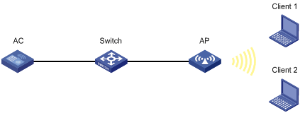
Configuration procedure
1. Click the network view tab at the bottom of the page.
2. Configure a wireless service:
a. From the navigation tree, select Wireless Configuration > Wireless Networks.
b. Add a wireless service:
- Create a wireless service named service.
- Set the SSID to service.
- Enable the wireless service.
3. Configure the AP:
a. From the navigation tree, select AP Management. You are placed on the AP tab.
b. Add and configure AP 1:
- Set the AP name to AP1 and the AP model to WA536-WW.
- Click the edit icon in the operation column for AP 1.
- Click the SSID setting tab, and bind the wireless service service to radio 1 of AP 1.
4. Configure client rate limiting:
a. From the navigation tree, select Wireless Configuration > Wireless QoS. You are placed on the Client Rate Limiting tab.
b. Click the more icon in the service configuration area.
c. Select the service name service, and click the edit icon for the wireless service service.
d. On the edit page, perform the following tasks:
- Enable client rate limiting.
- Set the limit mode to static mode for inbound traffic.
- Set the per-client limit rate to 8000 for inbound traffic.
- Set the limit mode to dynamic mode for outbound traffic.
- Set the total limit rate to 8000 for outbound traffic.
5. Enable radio 1 for AP 1:
a. From the navigation tree, select Wireless Configuration > Radio Management. You are placed on the Radio Configuration tab.
b. Click the details icon in the all AP radio configuration area.
c. Select the combination of AP 1 and radio 1, and click the corresponding edit icon.
d. On the edit page, enable radio 1.
Bandwidth guaranteeing configuration example
Network requirements
As shown in Figure 64, Clients 1, 2, and 3 access the network through the SSIDs research, office, and entertain, respectively.
For the network to operate correctly, guarantee 20% of the bandwidth for the SSID office, 80% for research, and none for entertain.
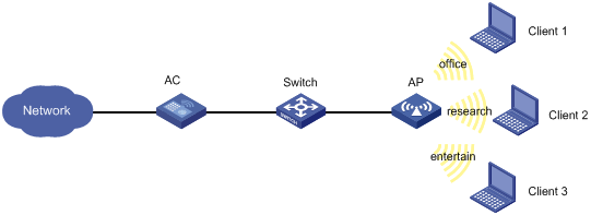
Configuration procedure
1. Click the network view tab at the bottom of the page.
2. Configure a wireless service:
a. From the navigation tree, select Wireless Configuration > Wireless Networks.
b. Add wireless services:
- Create wireless services named office, research, and entertain.
- Set their SSID to office, research, and entertain, respectively.
- Enable the wireless services.
3. Configure the AP:
a. From the navigation tree, select AP Management. You are placed on the AP tab.
b. Add and configure AP 1:
- Set the AP name to AP1 and the AP model to WA536-WW.
- Click the edit icon in the operation column for AP 1.
- Click the wireless service setting tab, and bind the wireless services office, research, and entertain to radio 1 of AP 1.
4. Configure bandwidth guaranteeing:
a. From the navigation tree, select Wireless Configuration > Wireless QoS.
b. Click the Bandwidth Guaranteeing tab.
c. Click the more icon in the AP configuration area.
d. Select the combination of AP 1 and radio 1, and click the edit icon.
e. On the edit page, perform the following tasks:
- Enable bandwidth guaranteeing.
- Set the guaranteed bandwidth percentage to 20% for the wireless service office.
- Set the guaranteed bandwidth percentage to 80% for the wireless service research.
5. Enable radio 1 for AP 1:
a. From the navigation tree, select Wireless Configuration > Radio Management. You are placed on the Radio Configuration tab.
b. Click the details icon in the all AP radio configuration area.
c. Select the combination of AP 1 and radio 1, and click the corresponding edit icon.
d. On the edit page, enable radio 1.
Verifying the configuration
# View details about AP configuration to verify that the effective bandwidth percentage for each SSID is not greater than the guaranteed bandwidth percentage.
Shared key authentication configuration example
Network requirements
As shown in Figure 65, the switch functions as a DHCP server to assign IP addresses to the AP and client. Configure shared key authentication to enable the client to access the network by using the WEP key 12345.

Configuration procedure
1. Click the network view tab at the bottom of the page.
2. Configure a wireless service:
a. From the navigation tree, select Wireless Configuration > Wireless Networks.
b. Add a wireless service:
- Create a wireless service named service1.
- Set the SSID to service.
- Enable the wireless service.
3. Click Apply and Set Advanced, and then click the Authentication tab.
4. Configure static WEP authentication:
¡ Set the security type to static WEP.
¡ Set the key type to Passphrase.
¡ Select the WEP 40 cipher suite.
¡ Set the key to 12345.
5. Apply the wireless service.
6. Bind the wireless service service1 to the AP:
a. From the navigation tree, select Wireless Configuration > Wireless Networks.
b. Select service1 and click Bind to APs.
c. Select the 5GHz radio of the AP and click Quick Bind.
Verifying the configuration
View details about the wireless service service1 to verify that the configuration is correct.
PSK authentication and bypass authentication configuration example
Network requirements
As shown in Figure 66, the switch functions as a DHCP server to assign IP addresses to the AP and client.
· Configure open system authentication and bypass authentication.
· Configure the client to use the preshared key 12345678 to access the network.
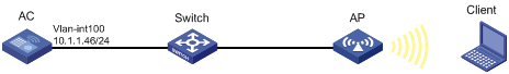
Configuration procedure
1. Click the network view tab at the bottom of the page.
2. Configure a wireless service:
a. From the navigation tree, select Wireless Configuration > Wireless Networks.
b. Add a wireless service:
- Create a wireless service named service1.
- Set the SSID to service.
- Enable the wireless service.
3. Click Apply and Set Advanced, and then click the Authentication tab.
4. Configure static PSK authentication:
¡ Set the security type to static PSK.
¡ Set the security mode to WPA.
¡ Select the CCMP cipher suite.
¡ Set the key type to Passphrase and the key to 12345678.
5. Apply the wireless service.
6. Bind the wireless service service1 to the AP:
a. From the navigation tree, select Wireless Configuration > Wireless Networks.
b. Select service1 and click Bind to APs.
c. Select the 5GHz radio of the AP and click Quick Bind.
Verifying the configuration
View details about the wireless service service1 to verify that the configuration is correct.
PSK authentication and MAC authentication configuration example
Network requirements
As shown in Figure 67, the switch functions as a DHCP server to assign IP addresses to the AP and client.
· Configure open system authentication and MAC authentication for clients.
· Configure the client to use the preshared key 12345678 to access the network.
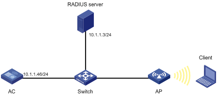
Configuration procedure
1. On the RADIUS server, configure the client's MAC address as the username and password used for authentication. The MAC address cannot contain hyphens and upper case letters.
2. Configure the RADIUS server correctly to provide authentication, authorization, and accounting functions.
3. Configure RADIUS and an authentication domain.
4. Click the network view tab at the bottom of the page.
5. Configure a wireless service:
a. From the navigation tree, select Wireless Configuration > Wireless Networks.
b. Add a wireless service:
- Create a wireless service named service1.
- Set the SSID to service.
- Enable the wireless service.
6. Click Apply and Set Advanced, and then click the Authentication tab.
7. Configure static PSK authentication and MAC authentication:
¡ Set the security type to static PSK and select MAC authentication.
¡ Set the security mode to WPA.
¡ Select the CCMP cipher suite.
¡ Set the key type to Passphrase and the key to 12345678.
¡ Set the domain name to dom1.
8. Apply the wireless service.
9. Bind the wireless service service1 to the AP:
a. From the navigation tree, select Wireless Configuration > Wireless Networks.
b. Select service1 and click Bind to APs.
c. Select the 5GHz radio of the AP and click Quick Bind.
Verifying the configuration
View details about the wireless service service1 to verify that the configuration is correct.
802.1X RADIUS authentication configuration example
Network requirements
As shown in Figure 68, configure the AC to meet the following requirements:
· Use the RADIUS server to perform authentication, authorization, and accounting for 802.1X users.
· Authenticate all 802.1X users who access the AC through GigabitEthernet 1/0/1 in the ISP domain dm1X.
· Use MAC-based access control on GigabitEthernet 1/0/1 to authenticate all 802.1X users on the port separately.
· Exclude domain names from the usernames sent to the RADIUS server.
· Use name as the authentication and accounting shared keys for secure RADIUS communication between the AC and the RADIUS server.
· Use ports 1812 and 1813 for authentication and accounting, respectively.
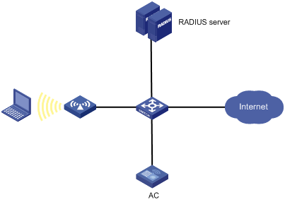
Configuration procedure
1. Assign an IP address to each interface, as shown in Figure 68. (Details not shown.)
2. On the AC, click the system view tab at the bottom of the page.
3. Configure a RADIUS scheme on the AC:
a. From the navigation tree, select Network Security > Authentication.
b. Click the RADIUS tab.
c. Add and configure a RADIUS scheme:
- Set the name of the RADIUS scheme to 802.1X.
- Configure the primary authentication server: set its IP address to 10.1.1.1, set the port number to 1812, set the shared key to name, and set the state to Active.
- Configure the primary accounting server: set its IP address to 10.1.1.1, set the port number to 1813, set the shared key to name, and set the state to Active.
- Set the format of usernames sent to the RADIUS server to Excludes the domain name.
4. Configure an ISP domain on the AC:
a. Click the ISP domains tab.
b. Add and configure an ISP domain:
- Set the domain name to dm1X.
- Set the ISP domain state to Active.
- Set the service type to LAN access.
- Set the method and scheme for authentication, authorization, and accounting to RADIUS and 802.1X, respectively.
5. Configure 802.1X on the AC:
a. From the navigation tree, select Access Control. You are placed on the 802.1X tab.
b. Enable 802.1X globally.
c. Enable 802.1X on GigabitEthernet 1/0/1, and specify MAC-based access control.
d. Access the advanced settings configuration page for GigabitEthernet 1/0/1 to perform the following tasks:
- Set the authorization state to Auto.
- Set the mandatory authentication domain to dm1X.
6. Configure the RADIUS server:
¡ Add a user account on the server. (Details not shown.)
¡ Configure the authentication, authorization, and accounting settings. (Details not shown.)
Verifying the configuration
1. Access the Network Security > Authentication > RADIUS page to verify brief information of the RADIUS scheme 802.1X.
2. Access the Network Security > Authentication > ISP Domains page to verify brief information of the ISP domain dm1X.
3. Verify that the use can come online:
a. Use the configured username and password to log in.
b. Access the Network Security > Access Control > 802.1X page to verify that the number of online users is 1 on GigabitEthernet 1/0/1.
802.1X local authentication configuration example
Network requirements
As shown in Figure 69, add a user account with the username dotuser and password 12345 on the AC. Configure the AC to meet the following requirements:
· Perform local 802.1X authentication to control the network access of users on GigabitEthernet 1/0/1.
· Authenticate the users in the ISP domain abc.
· Specify port-based access control on GigabitEthernet 1/0/1. After a user passes authentication on the port, all subsequent users can access the network without authentication.
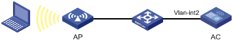
Configuration procedure
1. Assign an IP address to each interface, as shown in Figure 69. (Details not shown.)
2. Click the system view tab at the bottom of the page.
3. Configure a local user:
a. From the navigation tree, select Network Security > User Management. You are placed on the Local Authentication tab.
b. Add and configure a local user:
- Set the username to dotuser.
- Set the password to 12345.
- Set the service type to LAN access.
4. Configure an ISP domain:
a. From the navigation tree, select Authentication. You are placed on the ISP Domains tab.
b. Add and configure an ISP domain:
- Set the ISP domain name to abc.
- Set the ISP domain state to Active.
- Set the service type to LAN access.
- Configure the ISP domain to use local method for authentication and authorization of LAN users, and not perform accounting for LAN users.
5. Configure 802.1X:
a. From the navigation tree, select Access Control. You are placed on the 802.1X tab.
b. Enable 802.1X globally.
c. Enable 802.1X on GigabitEthernet 1/0/1, and specify port-based access control.
d. Access the advanced settings configuration page for GigabitEthernet 1/0/1 to perform the following tasks:
- Set the authorization state to Auto.
- Set the mandatory authentication domain to abc.
Verifying the configuration
1. Access the Network Security > User Management > Local Authentication page to verify the configuration of the local user dotuser.
2. Access the Network Security > Authentication > ISP Domains page to verify brief information of the ISP domain abc.
3. Verify that the use can come online:
a. Use the configured username and password to log in.
b. Access the Network Security > Access Control > 802.1X page to verify that the number of online users is 1 on GigabitEthernet 1/0/1.
802.1X AKM configuration example
Network requirements
As shown in Figure 70, the switch functions as a DHCP server to assign IP addresses to the AP and client.
· Configure open system authentication and 802.1X authentication so that the client can access the network by using the login username abcdef and password 123456.
· Configure 802.1X as the AKM mode.
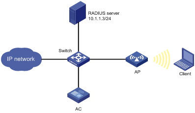
Configuration procedure
1. Configure the username abcdef and the password 123456 on the RADIUS server and make sure the RADIUS server and AC can reach each other. (Details not shown.)
2. Configure RADIUS and an authentication domain.
3. Click the network view tab at the bottom of the page.
4. Configure a wireless service:
a. From the navigation tree, select Wireless Configuration > Wireless Networks.
b. Add a wireless service:
- Create a wireless service named service1.
- Set the SSID to service.
- Enable the wireless service.
5. Click Apply and Set Advanced, and then click the Authentication tab.
6. Configure 802.1X authentication:
¡ Set the security type to 802.1X authentication.
¡ Set the security mode to WPA.
¡ Select the CCMP cipher suite.
¡ Set the domain name to dom1.
7. Apply the wireless service.
8. Bind the wireless service service1 to the AP:
a. From the navigation tree, select Wireless Configuration > Wireless Networks.
b. Select service1 and click Bind to APs.
c. Select the 5GHz radio of the AP and click Quick Bind.
Verifying the configuration
# View details about the wireless service service1 to verify that the configuration is correct.
Direct portal authentication configuration example
Network requirements
As shown in Figure 71, the AP directly forwards user traffic from the client. The client is assigned with a public IP address either manually or through DHCP. A portal server acts as both a portal authentication server and a portal Web server. A RADIUS server acts as the authentication/accounting server.
Configure direct portal authentication, so the client can access only the portal Web server before passing the authentication and access Internet resources after passing the authentication.
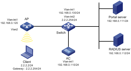
Configuration procedures
1. Configure IP addresses for the client, AC, and servers as shown in Figure 71 and make sure they can reach each other.
2. Configure the RADIUS server correctly to provide authentication and accounting functions.
3. Configure the AP to make sure the AP can communicate with the AC.
4. Configure RADIUS and an authentication domain.
· Configure a wireless service:
a. From the navigation tree, select Wireless Configuration > Wireless Networks.
b. Add a wireless service:
- Create a wireless service named service1.
- Set the SSID to service.
- Enable the wireless service.
5. Configure the portal authentication mode:
a. Click the edit icon for wireless service service1.
The advanced settings page opens.
b. Click the Authentication tab.
c. Select With Portal Authentication.
d. Set the domain name to dm1.
e. Set the server URL to newpt.
f. Set the BAS-IP to 192.168.0.110.
g. Click Apply.
6. Bind the wireless service1 to the AP:
a. From the navigation tree, select Wireless Configuration > Wireless Networks.
b. Select service1 and click Bind to APs.
c. Select the 5GHz radio of the AP and click Bind.
The Bind to AP window opens.
d. Enter 2 in the Bound VLAN field.
e. Click Apply.
Verifying the configuration
# View details about the service service1 to verify that the configuration is correct.
WLAN RRM DFS configuration example
Network requirements
As shown in Figure 72, configure auto-DFS to adjust channels for the APs when a channel adjustment trigger condition is met. Add radio 1 of AP 1 to an RRM holddown group to avoid frequent channel adjustments.
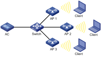
Configuration procedure
1. Click the network view tab at the bottom of the page.
2. Specify a working channel for each AP:
a. From the navigation tree, select Wireless Configuration > Radio Management. You are placed on the Radio Configuration tab.
b. Access the details page for radio configuration and set the working channel to Auto unlock for AP 1, AP 2, and AP 3.
3. Configure auto-DFS:
a. From the navigation tree, select Wireless Configuration > Radio Management.
b. Click the RRM tab.
c. Access the details page for AP configuration to perform the following tasks for AP 1, AP 2, and AP 3:
- Enable auto-DFS.
- Select Custom for the DFS sensitivity parameter, and set the tolerance level, CRC error threshold, and interference threshold to 25, 30, and 60, respectively.
d. Access the details page for RRM holddown group configuration to perform the following tasks:
- Create RRM holddown group 10.
- Set the channel holddown time to 600 minutes.
e. Add the 5 GHz radio of AP 1 to RRM holddown group 10.
Verifying the configuration
# On the Monitoring > RF Monitoring > RRM page, verify the following information:
· The working channels for the APs change when a channel adjustment trigger condition is met and the calibration interval is reached.
· The channel for radio 1 on AP 1 remains unchanged within 600 minutes after the first DFS.
WLAN RRM TPC configuration example
Network requirements
As shown in Figure 73, configure auto-TPC and set the neighbor number threshold as 3 to enable the AC to perform auto-TPC when AP 4 joins. Add radio 1 of AP 1 to an RRM holddown group to avoid frequent power adjustments.
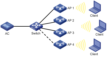
Configuration procedure
1. Click the network view tab at the bottom of the page.
2. Disable power lock for the APs:
a. From the navigation tree, select Wireless Configuration > Radio Management. You are placed on the Radio Configuration tab.
b. Access the details page for radio configuration to disable power lock for AP 1, AP 2, AP 3, and AP 4.
3. Configure auto-TPC:
a. From the navigation tree, select Wireless Configuration > Radio Management.
b. Click the RRM tab.
c. Access the details page for AP configuration to perform the following tasks for AP 1, AP 2, AP 3, and AP 4:
- Enable auto-TPC.
- Set the TPC mode to Custom.
- Set the adjacency factor, power adjustment threshold, and minimum transmit power to 3, ‑70 dBm, and 5 dBm, respectively.
d. Access the details page for RRM holddown group configuration to perform the following tasks:
- Create RRM holddown group 10.
- Set the power holddown time to 100 minutes.
e. Add the 5 GHz radio of AP 1 to RRM holddown group 10.
Verifying the configuration
# On the Monitoring > RF Monitoring > RRM page, verify the following information:
· The power values for the APs change when the power adjustment threshold and the calibration interval are reached.
· The power for radio 1 on AP 1 remains unchanged within 100 minutes after the first TPC.
Session-mode load balancing configuration example for radios
Network requirements
As shown in Figure 74, AP 1 and AP 2 are managed by the AC and the clients can discover the APs.
Configure the AC to perform session-mode load balancing on AP 1 and AP 2 when the following conditions are met:
· The number of sessions on one AP reaches 3.
· The session gap between the APs reaches 2.
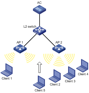
Configuration procedure
1. Click the network view tab at the bottom of the page.
2. Configure a wireless service:
a. From the navigation tree, select Wireless Configuration > Wireless Networks.
b. Add a wireless service:
- Create a wireless service named service.
- Set the SSID to session-balance.
- Enable the wireless service.
3. Configure the APs:
a. From the navigation tree, select AP Management. You are placed on the AP tab.
b. Add and configure AP 1:
- Set the AP name to AP1 and the AP model to WA536-WW.
- Click the edit icon in the operation column for AP 1.
- Click the wireless service setting tab, and bind the wireless service service to the radio of AP 1.
c. Add and configure AP 2 in the same way AP 1 is added and configured.
4. Configure load balancing:
a. From the navigation tree, select Wireless Configuration > Radio Management.
b. Click the Load Balancing tab.
c. Access the details page for global configuration to perform the following tasks:
- Enable load balancing.
- Select Session Mode.
- Set the session threshold to 3 and the session gap to 2.
Verifying the configuration
# Verify that the AC performs session-mode load balancing for AP 1 and AP 2 when the following conditions are met:
· The number of sessions on one AP reaches 3.
· The session gap between the APs reaches 2.
# On the Monitoring > Clients page, verify that AP 1 and AP 2 are load balanced.
Traffic-mode load balancing configuration example for radios
Network requirements
As shown in Figure 75, AP 1 and AP 2 are managed by the AC and the clients can discover the APs. The maximum bandwidth for each AP is 150 Mbps.
Configure the AC to perform traffic-mode load balancing on AP 1 and AP 2 when the following conditions are met:
· The traffic on one AP reaches 30 Mbps (20% of the maximum bandwidth).
· The traffic gap between the APs reaches 15 Mbps (10% of the maximum bandwidth).
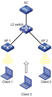
Configuration procedure
1. Click the network view tab at the bottom of the page.
2. Configure a wireless service:
a. From the navigation tree, select Wireless Configuration > Wireless Networks.
b. Add a wireless service:
- Create a wireless service named service.
- Set the SSID to traffic-balance.
- Enable the wireless service.
3. Configure the APs:
a. From the navigation tree, select AP Management. You are placed on the AP tab.
b. Add and configure AP 1:
- Set the AP name to AP1 and the AP model to WA536-WW.
- Click the edit icon in the operation column for AP 1.
- Click the wireless service setting tab, and bind the wireless service service to the radio of AP 1.
c. Add and configure AP 2 in the same way AP 1 is added and configured.
4. Configure load balancing:
a. From the navigation tree, select Wireless Configuration > Radio Management.
b. Click the Load Balancing tab.
c. Access the details page for global configuration to perform the following tasks:
- Enable load balancing.
- Select Traffic Mode.
- Set the traffic threshold to 20 and the traffic gap to 10.
Verifying the configuration
# Verify that the AC performs session-mode load balancing for AP 1 and AP 2 when the following conditions are met:
· The traffic of one AP reaches 30 Mbps.
· The traffic gap between the APs reaches 15 Mbps.
# On the Monitoring > Clients page, verify that AP 1 and AP 2 are load balanced.
Bandwidth-mode load balancing configuration example for radios
Network requirements
As shown in Figure 76, AP 1 and AP 2 are managed by the AC and the clients can discover the APs.
Configure the AC to perform bandwidth-mode load balancing on AP 1 and AP 2 when the following conditions are met:
· The bandwidth of one AP reaches 12 Mbps.
· The bandwidth gap between the APs reaches 3 Mbps.

Configuration procedure
1. Click the network view tab at the bottom of the page.
2. Configure a wireless service:
a. From the navigation tree, select Wireless Configuration > Wireless Networks.
b. Add a wireless service:
- Create a wireless service named service.
- Set the SSID to bandwidth-balance.
- Enable the wireless service.
3. Configure the APs:
a. From the navigation tree, select AP Management. You are placed on the AP tab.
b. Add and configure AP 1:
- Set the AP name to AP1 and the AP model to WA536-WW.
- Click the edit icon in the operation column for AP 1.
- Click the SSID setting tab, and bind the wireless service service to the radio of AP 1.
c. Add and configure AP 2 in the same way AP 1 is added and configured.
4. Configure load balancing:
a. From the navigation tree, select Wireless Configuration > Radio Management.
b. Click the Load Balancing tab.
c. Access the details page for global configuration to perform the following tasks:
- Enable load balancing.
- Select Bandwidth Mode.
- Set the bandwidth threshold to 12 and the bandwidth gap to 3.
Verifying the configuration
# Verify that the AC performs bandwidth-mode load balancing for AP 1 and AP 2 when the following conditions are met:
· The bandwidth of one AP reaches 12 Mbps.
· The bandwidth gap between the APs reaches 3 Mbps.
# On the Monitoring > Clients page, verify that AP 1 and AP 2 are load balanced.
Session-mode load balancing configuration example for a load balancing group
Network requirements
As shown in Figure 77, AP 1, AP 2, and AP 3 are managed by the AC and the clients can discover the APs.
Configure the AC to perform session-mode load balancing on radio 2 of AP 1 and radio 2 of AP 2 when the following conditions are met:
· The number of sessions on one radio reaches 3.
· The session gap between the radios reaches 2.
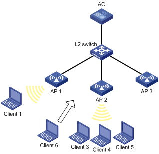
Configuration procedure
1. Click the network view tab at the bottom of the page.
2. Configure a wireless service:
a. From the navigation tree, select Wireless Configuration > Wireless Networks.
b. Add a wireless service:
- Create a wireless service named service.
- Set the SSID to session-balance.
- Enable the wireless service.
3. Configure the APs:
a. From the navigation tree, select AP Management. You are placed on the AP tab.
b. Add and configure AP 1:
- Set the AP name to AP1 and the AP model to WA536-WW.
- Click the edit icon in the operation column for AP 1.
- Click the wireless service setting tab, and bind the wireless service service to the radio of AP 1.
c. Add and configure AP 2 and AP 3 in the same way AP 1 is added and configured.
4. Configure load balancing:
a. From the navigation tree, select Wireless Configuration > Radio Management.
b. Click the Load Balancing tab.
c. Access the details page for global configuration to perform the following tasks:
- Enable load balancing.
- Select Session Mode.
- Set the session threshold to 3 and the session gap to 2.
d. Access the details page for load balancing group configuration to perform the following tasks:
- Create a load balancing group.
- Bind radio 2 of AP 1 and AP 2 to the load balancing group.
Verifying the configuration
# Verify that the AC performs session-mode load balancing for radio 2 of AP 1 and radio 2 of AP 2 when the following conditions are met:
· The number of sessions on one radio reaches 3.
· The session gap between the radios reaches 2.
# On the Monitoring > Clients page, verify that AP 1 and AP 2 are load balanced.
Traffic-mode load balancing configuration example for a load balancing group
Network requirements
As shown in Figure 78, AP 1, AP 2, and AP 3 are managed by the AC and the clients can discover the APs. The maximum bandwidth for each AP is 150 Mbps.
Configure the AC to perform traffic-mode load balancing on radio 2 of AP 1 and radio 2 of AP 2 when the following conditions are met:
· The traffic of one radio reaches 30 Mbps (20% of the maximum bandwidth).
· The traffic gap between the radios reaches 15 Mbps (10% of the maximum bandwidth).
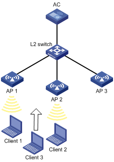
Configuration procedure
1. Click the network view tab at the bottom of the page.
2. Configure a wireless service:
a. From the navigation tree, select Wireless Configuration > Wireless Networks.
b. Add a wireless service:
- Create a wireless service named service.
- Set the SSID to traffic-balance.
- Enable the wireless service.
3. Configure the APs:
a. From the navigation tree, select AP Management. You are placed on the AP tab.
b. Add and configure AP 1:
- Set the AP name to AP1 and the AP model to WA536-WW.
- Click the edit icon in the operation column for AP 1.
- Click the wireless service setting tab, and bind the wireless service service to the radio of AP 1.
c. Add and configure AP 2 and AP 3 in the same way AP 1 is added and configured.
4. Configure load balancing:
a. From the navigation tree, select Wireless Configuration > Radio Management.
b. Click the Load Balancing tab.
c. Access the details page for global configuration to perform the following tasks:
- Enable load balancing.
- Select Traffic Mode.
- Set the traffic threshold to 20 and the traffic gap to 10.
d. Access the details page for load balancing group configuration to perform the following tasks:
- Create a load balancing group.
- Bind radio 2 of AP 1 and AP 2 to the load balancing group.
Verifying the configuration
# Verify that the AC performs traffic-mode load balancing for radio 2 of AP 1 and radio 2 of AP 2 when the following conditions are met:
· The traffic of one radio reaches 30 Mbps.
· The traffic gap between the radios reaches 15 Mbps.
# On the Monitoring > Clients page, verify that AP 1 and AP 2 are load balanced.
Bandwidth-mode load balancing configuration example for a load balancing group
Network requirements
As shown in Figure 79, AP 1, AP 2, and AP 3 are managed by the AC and the clients can discover the APs.
Configure the AC to perform bandwidth-mode load balancing on radio 2 of AP 1 and radio 2 of AP 2 when the following conditions are met:
· The bandwidth of one radio reaches 12 Mbps.
· The bandwidth gap between the radios reaches 3 Mbps.

Configuration procedure
1. Click the network view tab at the bottom of the page.
2. Configure a wireless service:
a. From the navigation tree, select Wireless Configuration > Wireless Networks.
b. Add a wireless service:
- Create a wireless service named service.
- Set the SSID to bandwidth-balance.
- Enable the wireless service.
3. Configure the APs:
a. From the navigation tree, select AP Management. You are placed on the AP tab.
b. Add and configure AP 1:
- Set the AP name to AP1 and the AP model to WA536-WW.
- Click the edit icon in the operation column for AP 1.
- Click the wireless service setting tab, and bind the wireless service service to the radio of AP 1.
c. Add and configure AP 2 and AP 3 in the same way AP 1 is added and configured.
4. Configure load balancing:
a. From the navigation tree, select Wireless Configuration > Radio Management.
b. Click the Load Balancing tab.
c. Access the details page for global configuration to perform the following tasks:
- Enable load balancing.
- Select Bandwidth Mode.
- Set the bandwidth threshold to 12 and the bandwidth gap to 3.
d. Access the details page for load balancing group configuration to perform the following tasks:
- Create a load balancing group.
- Bind radio 2 of AP 1 and AP 2 to the load balancing group.
Verifying the configuration
# Verify that the AC performs bandwidth-mode load balancing for radio 2 of AP 1 and radio 2 of AP 2 when the following conditions are met:
· The bandwidth of one radio reaches 12 Mbps.
· The bandwidth gap between the radios reaches 3 Mbps. (Details not shown.)
# On the Monitoring > Clients page, verify that AP 1 and AP 2 are load balanced.
Band navigation configuration example
Network requirements
As shown in Figure 80, both the 5 GHz radio and the 2.4 GHz radio are enabled on the AP. Configure band navigation and load balancing for band navigation to load balance the radios.
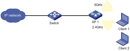
Configuration procedure
1. Click the network view tab at the bottom of the page.
2. Configure a wireless service:
a. From the navigation tree, select Wireless Configuration > Wireless Networks.
b. Access the page for adding a wireless network to perform the following tasks:
- Set the name of the wireless service to service.
- Set its SSID to band-navigation.
- Disable fast association.
- Enable the wireless service.
3. Configure AP 1:
a. From the navigation tree, select Wireless Configuration > AP Management.
b. Click the AP tab.
c. Access the configuration page for AP 1 and click the wireless service setting tab.
d. Bind the wireless service service to both the 5 GHz and 2.4 GHz radios of AP 1.
4. Configure band navigation:
a. From the navigation tree, select Wireless Configuration > Radio Management.
b. Click the Band Navigation tab.
c. Access the details page for global configuration to perform the following tasks:
- Enable band navigation globally.
- Set the session threshold to 5.
- Set the session gap threshold to 2.
d. Access the band navigation configuration page for AP 1 to enable band navigation for AP 1.
Verifying the configuration
# On the Monitoring > Clients page, verify that the 5 GHz radio and the 2.4 GHz radio of AP 1 are load balanced.
Wireless locating configuration example
Network requirements
As shown in Figure 81, configure wireless locating on AP 1, AP 2, and AP 3 to locate the MU and the Tag.
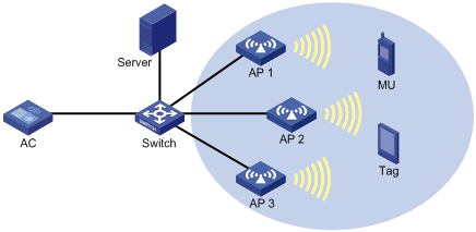
Configuration procedure
1. Configure the locating server:
¡ Set the IP addresses of the three APs on the locating server, or configure the locating server to discover APs through broadcast. (Details not shown.)
¡ Configure wireless locating on the locating server. (Details not shown.)
2. Click the network view tab at the bottom of the page.
3. Configure a wireless service:
a. From the navigation tree, select Wireless Configuration > Wireless Networks.
b. Access the page for adding a wireless service to perform the following tasks:
- Set the wireless service name to market.
- Enable the wireless service.
4. Configure AP 1:
a. From the navigation tree, select Wireless Configuration > AP Management. You are placed on the AP tab.
b. Access the page for adding an AP to perform the following tasks:
- Set the AP name to AP1.
- Select the AP model WA536-WW.
- Set the serial ID.
c. Click the edit icon in the operation column for AP 1 to perform the following tasks:
- Click the wireless service setting tab.
- Bind the wireless service market to radio 1 of the AP AP1.
d. From the navigation tree, select Wireless Configuration > Applications.
e. Click the Location Aware tab.
f. Access the details page for global configuration.
g. Click the Aeroscout configuration tab.
h. Enable Aeroscout locating.
i. Access the details page for AP configuration to perform the following tasks:
- Access the edit page for the AP AP1. You are placed on the Common tab.
- Enable ignoring beacon frames.
- Click the Aeroscout tab.
- Enable AeroScout locating.
- Enable radio 1.
- Select both the MU and Tag.
5. Configure AP 2 and AP 3 in the same way AP 1 is configured.
Verifying the configuration
# Verify that you can view the locating information about the MU and the Tag by using maps, forms, or reports provided by the graphics software. (Details not shown.)
Network security configuration examples
BYOD configuration example
Network requirements
As shown in Figure 82, perform the following tasks for the AC to perform 802.1X authentication on the client:
· Set the username and password for 802.1X authentication to dotuser and 12345, respectively.
· Set the authentication method to open system for the AC to perform local authentication and authorization for the client, and set the authentication domain name to abc.
· Allow the client that runs Microsoft Windows 8 to access VLAN 3 after passing the authentication.
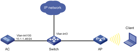
Configuration procedure
1. Assign an IP address to each interface. (Details not shown.)
2. Click the network view tab at the bottom of the page.
3. Configure a wireless service:
a. From the navigation tree, select Wireless Configuration > Wireless Networks.
b. Access the page for adding a wireless service to perform the following tasks:
- Set the wireless service name to service1.
- Set the SSID to service.
- Enable the wireless service.
4. Configure 802.1X:
a. From the navigation tree, select Wireless Configuration > Wireless Networks.
b. Access the advanced settings configuration page for the wireless service service1 to perform the following tasks:
- Set the security type to 802.1X authentication.
- Set the security mode to WPA.
- Select the CCMP cipher suite.
- Set the domain name.
5. Bind the wireless service to the AP:
a. From the navigation tree, select Wireless Configuration > Wireless Networks.
b. Select the wireless service service1, and click the bind to APs button.
c. Select the 5 GHz radio of the AP, and then click the quick bind button.
6. Configure an ISP domain:
a. From the navigation tree, select Network Security > Authentication. You are placed on the ISP Domains tab.
b. Add an ISP domain, and then set its state to active.
c. Set the service type to LAN Access.
d. Set the authentication, authorization, and accounting methods to Local, Local, and None, respectively.
7. Configure a local user:
a. From the navigation tree, select Network Security > User Management. You are placed on the Local Authentication tab.
b. Click User groups.
c. Click the add icon.
d. Add a user group named windows8.
e. Click Apply.
f. On the Local Authentication tab, click Users.
g. Click the add icon.
h. Add a user named dotuser, and then set the password to 12345.
i. Set the service type to LAN Access.
j. Specify the user group windows8.
k. Click Apply.
8. Configure BYOD authorization:
a. From the navigation tree, select Network Security > BYOD.
b. Click the BYOD Authorization tab.
c. Set the terminal type to Microsoft Windows 8.
d. Set the ACL number to 2000.
e. Set the authorization VLAN to VLAN 3.
f. Click Apply.
9. Configure BYOD rules:
a. From the navigation tree, select Network Security > BYOD. You are placed on the BYOD Rules tab.
b. Add a DHCP rule:
- Set the DHCP Option 55 value to 1,15,3,6,44,46,47,31,33,121,249,252,43.33.
- Set the terminal type to Microsoft Windows 8.
Verifying the configuration
# Verify that the client can access the resources in VLAN 3 after passing 802.1X authentication.
Guest management configuration example
Network requirements
Configure guest management on the AC as follows:
· Create a guest account user1 for Jack, and set the password, user group, personal profiles, validity period, and receptionist information.
· Configure the SMTP server address, sender address, and guest administrator's email address that are used to send emails.
· Configure the subject and contents of the Emails to be sent to the guest, receptionist, and guest administrator.
· Configure the system to automatically delete expired guest accounts.
Figure 83 Network diagram
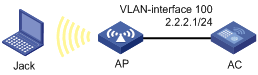
Configuration procedures
1. Configure IP addresses for interfaces. (Details not shown.)
2. Configure wireless services. (Details not shown.)
3. Add a guest account:
a. Click the network view tab at the bottom of the page.
b. From the navigation tree, select Network Security > Guest Management.
c. On the Guest List tab, click the add icon.
d. On the Add Guest page, perform the following tasks:
- Set the account and password to user1 and 123456, respectively.
- Select a group for the guest.
- Enter the full name, company, Email address, phone number, and description of the guest.
- Enter the sponsor's full name, department, and Email address.
- Set the validity period.
4. Configure the guest service parameters:
a. Click the network view tab at the bottom of the page.
b. From the navigation tree, select Network Security > Guest Management.
c. Click the Guest Configuration tab.
d. Select Auto delete.
e. Set the SMTP server address to smtp://192.168.0.112/smtp.
f. Set the email sender address to [email protected].
g. Set the guest manager email address to [email protected].
h. Set the subject of notifications to guests to Guest account information, and set the body to A guest account has been created for your use. The username, password, and valid dates for the account are given below..
i. Set the subject of notifications to guest managers to Guest register information, and set the body to A guest account has been registered. The username for the account is given below. Please approve the register information..
j. Set the subject of notifications to guest sponsors to Guest account information, and set the body to A guest account has been created. The username, password, and valid dates for the account are given below..
Verifying the configuration
# Verify that guest Jack can access the network after passing local authentication by using username user1 and password 123456.
Tools configuration examples
Local packet capture configuration example
Network requirements
As shown in Figure 84, enable local packet capture on radio 1 of the AP to capture 1 KB of TCP packets sourced from 192.168.20.173. The switch acts as the FTP server for storing the captured packets sent by the AP.
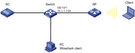
Configuration procedure
1. Configure the switch:
a. Create a device management user named abc.
b. Set the password for the user to 123456.
c. Specify the user role for the user as network-admin.
d. Specify the working directory flash:/ for the user.
e. Specify the service type for the user as ftp.
f. Enable the FTP server on the switch.
2. Configure local packet capture:
a. Click the network view tab at the bottom of the page.
b. From the navigation tree, select Tools > Wireless Capture.
c. Select radio 1 of the AP.
d. Configure wireless capture:
- Select the local packet capture mode.
- Specify the capture filter as src 192.168.20.173 and tcp.
- Set the maximum frame size to 8000 bytes.
- Set the file size to 1 KB.
- Set the FTP URL to ftp://10.1.1.1.
- Set the FTP username to abc.
- Set the FTP password to 123456.
Verifying the configuration
# Verify that the captured packets can be displayed on the PC after the Wireshark client is connected to the FTP server.
Remote packet capture configuration example
Network requirements
As shown in Figure 85, enable remote packet capture on radio 1 of the AP and use Wireshark to display the captured packets.
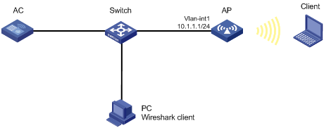
Configuration procedure
1. Configure remote packet capture:
a. Click the network view tab at the bottom of the page.
b. From the navigation tree, select Tools > Wireless Capture.
c. Select radio 1 of the AP.
d. Select the remote packet capture mode.
e. Set the RPCAP port to 2014.
2. Display captured packets on the PC:
a. Start Wireshark and select Capture > Options.
b. Select Remote from the Interface list.
c. Enter the IP address 10.1.1.1 and the port number 2014, and click OK.
d. Click Start.
The captured packets are displayed on the page that appears.
Figure 86 Displaying the captured packets on the Wireshark
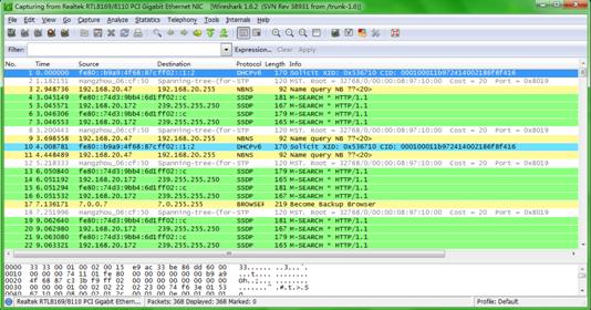
AC backup,84
Access control,124
Access control methods,115
Access control methods,59
ACL,66
ACL types and match criteria,67
ACL-based packet filter configuration example,162
Administrators,72
Administrators configuration example,165
Advanced settings,38
Aggregation group,23
Aggregation states of member ports in an aggregation group,23
Aging timer for dynamic MAC address entries,29
All networks menu in network view,20
AP group configuration example,170
AP groups,82
AP management,81
AP preprovisioning,83
ARP,46
ARP attack protection,48
ARP attack protection configuration example,158
Attribute settings,23
Authentication mode,80
Authentication trigger,60
Authentication trigger,116
Auth-Fail VLAN,116
Auth-Fail VLAN,60
Auto AP,84
Auto AP configuration example,169
Band navigation,112
Band navigation configuration example,197
Bandwidth guaranteeing configuration example,176
Bandwidth guaranteeing features,85
Bandwidth-mode load balancing configuration example for a load balancing group,195
Bandwidth-mode load balancing configuration example for radios,191
Baseline,110
Basic radio functions,103
Building a capture filter,128
BYOD,122
BYOD authorization,123
BYOD configuration example,199
BYOD endpoint identification rules,122
Capture filter keywords,125
Capture filter operators,127
CAPWAP tunnel,81
CAPWAP tunnel establishment through DHCP configuration example,167
CAPWAP tunnel establishment through DNS configuration example,168
Channel,96
Channel scanning,110
Client probing,112
Client rate limit methods,85
Client rate limit mode,84
Client rate limiting configuration example,175
Client rate limiting features,84
Client WMM statistics,86
Concurrent login users,1
Configuration prerequisites,84
Configuration restrictions and guidelines,108
Configuring a VSD,87
Configuring attack detection,90
Configuring device classification,87
Configuring the alarm-ignored device list,95
Countermeasures,95
Critical VLAN,118
Critical VLAN,62
Dashboard menu,15
Dashboard menu,9
DDNS,45
Default login settings,1
DHCP,41
DHCP relay agent,43
DHCP relay agent configuration example,147
DHCP server,41
DHCP server configuration example,146
DHCP snooping,43
DHCP snooping configuration example,148
Direct portal authentication configuration example,184
Directories,70
Displaying settings of a table entry,8
DNS,44
DNS proxy,45
Dynamic domain name resolution,44
Dynamic frequency selection,109
Dynamic NAT,36
Dynamic NAT 444 configuration example,142
EAD assistant,120
EAD assistant,64
EDCA parameters and ACK policies,86
EDCA parameters of AC queues for clients,86
Enabling WIPS,87
Enhanced RADIUS features,122
Enhanced RADIUS features,66
EUI-64 address-based interface identifiers,35
Feature navigator in network view,15
Feature navigator in system view,9
File management,71
File system management,69
File system management restrictions and guidelines,71
File systems,69
Files,71
Filter elements,125
FTP,54
Global configuration,83
Gratuitous ARP,47
Guest management,123
Guest management configuration example,201
Guest VLAN,117
Guest VLAN,61
HTTP/HTTPS,53
Icons and buttons,6
IGMP snooping,46
IGMP snooping configuration example,154
Inter-AC roaming configuration example,131
Intra-AC roaming configuration example,130
IP,32
IP address classes,32
IP address configuration methods,33
IPv4 DNS proxy configuration example,151
IPv4 dynamic DNS configuration example,150
IPv4 static DNS configuration example,149
IPv4 static route configuration example,143
IPv6,33
IPv6 address formats,33
IPv6 address types,34
IPv6 DNS proxy configuration example,153
IPv6 dynamic DNS configuration example,152
IPv6 global unicast address configuration methods,35
IPv6 link-local address configuration methods,35
IPv6 static DNS configuration example,152
IPv6 static route configuration example,144
ISP domains,120
ISP domains,64
Layer 2 dynamic aggregation configuration example,133
Layer 2 static aggregation configuration example,132
Link aggregation,22
Link aggregation modes,23
Link layer authentication,78
LLDP,55
LLDP agent,55
LLDP configuration example,161
LLDP reinitialization delay,56
LLDP TLVs,56
LLDP trapping,56
Load balancing modes,111
Load balancing parameters,111
Load balancing types,111
Local packet capture configuration example,202
Local users,66
Local users,123
Locating system,112
Log,56
Log destinations,57
Log levels,56
Logging in to the Web interface for the first time,2
Logging out of the Web interface,2
MAC,29
MAC address learning,30
MAC address table configuration example,135
Mandatory authentication domain,120
Mandatory authentication domain,64
Match order,67
MCS,97
MLD snooping,46
MLD snooping configuration example,156
Monitoring menu,16
MSTP basic concepts,30
MSTP configuration example,136
MTU for an interface,33
NAT,36
NAT Server,36
NAT Server for external-to-internal access configuration example,139
NAT444,37
ND,50
ND proxy,52
Neighbor entries,51
Network configuration menu,9
Network security configuration examples,162
Network security configuration examples,199
Network security menu,13
Network security menu,18
Network settings configuration examples,130
NTP,54
NTP configuration example,160
Online user handshake,60
Online user handshake,116
Operational key,23
Outbound dynamic NAT configuration example,138
Outbound static NAT configuration example,139
Overview,27
Overview,21
Packet capture,125
Packet filter,58
Packet processing,113
Password control,75
Performing basic tasks,7
Periodic online user reauthentication,116
Periodic online user reauthentication,60
Port authorization state,116
Port authorization state,60
Port priority,114
Port roles,31
Port security,124
Port states,31
Portal,124
Port-based VLANs,28
PPPoE,27
PPPoE client configuration example,134
PPPoE network structure,27
Priority map,115
Priority mapping,114
Priority mapping,58
Proxy ARP,47
Proxy ARP configuration example,157
PSK authentication and bypass authentication configuration example,178
PSK authentication and MAC authentication configuration example,179
QoS,114
QoS,58
QoS configuration example,163
QoS policies,114
QoS policies,58
Quick start menu,15
RA messages,51
Radio management,95
Radio management configuration example,171
Radio mode,95
RADIUS,66
RADIUS,122
RADIUS protocol,122
RADIUS protocol,66
Rebooting the device,8
Receiving LLDP frames,55
Region code,83
Remote packet capture configuration example,203
Reporting menu,19
Restrictions and guidelines,40
Restrictions and guidelines,1
Role-based access control,72
Routing table,31
RRM holddown group,110
Rule numbering,68
Saving the configuration,8
Session-mode load balancing configuration example for a load balancing group,192
Session-mode load balancing configuration example for radios,188
Settings,77
Shared key authentication configuration example,178
Signature-based attack detection configuration example,174
Spanning tree modes,30
SSH,54
Static domain name resolution,45
Static IPv6 address configuration example,145
Static NAT 444 configuration example,141
Static routing,32
STP,30
Subnetting and masking,32
System configuration examples,165
System menu,14
System menu,19
Telnet,54
Terminology,21
Time range,69
Tools configuration examples,202
Tools menu,15
Tools menu,19
Traffic statistics,86
Traffic-mode load balancing configuration example for a load balancing group,194
Traffic-mode load balancing configuration example for radios,189
Transmission rate,96
Transmit power,96
Transmit power control,110
Transmitting LLDP frames,55
Types of ARP table entries,46
Types of MAC address entries,29
Types of webpages,4
User account management,72
User-defined attack detection based on signatures,94
Using a configuration page,6
Using a feature page,5
Using a table page,5
Using the device as the Stelnet server for password authentication configuration example,159
VHT-MCS,98
VLAN,28
VLAN interface,29
Web browser requirements,1
Whitelist and blacklist features,95
WIPS,87
WIPS device classification and countermeasures configuration example,172
WIPS malformed packet and flood attack detection configuration example,173
Wireless configuration examples,167
Wireless configuration menu,16
Wireless locating,112
Wireless locating configuration example,198
Wireless locating mechanism,112
WLAN,78
WLAN access,78
WLAN load balancing,111
WLAN roaming,21
WLAN roaming mechanism,21
WLAN RRM,109
WLAN RRM DFS configuration example,186
WLAN RRM TPC configuration example,187
WMM features,85
WMM settings,85
WMM status,85