- Table of Contents
- Related Documents
-
| Title | Size | Download |
|---|---|---|
| 01-Text | 665.55 KB |
Multi-active handling procedure
Feature and hardware compatibility
General restrictions and configuration guidelines
IRF transceiver module restrictions
IRF network interface shutdown restrictions
Feature compatibility and configuration restrictions
Setup and configuration task list
Assigning the same IRF topo-domain ID to the member devices
Assigning a member ID to each IRF member device
Specifying a priority for each member device
Assigning links to an IRF port
General configuration restrictions and guidelines
Excluding a network interface from the shutdown action upon detection of multi-active collision
Configuring a member device description
Configuring IRF bridge MAC persistence
Configuration restrictions and guidelines
Enabling software auto-update for software image synchronization
Enabling IRF optimization for WLAN access
Maintaining the IRF memberships
Removing a device from the IRF fabric
Adding a removed member device back to the IRF fabric
Displaying and maintaining an IRF fabric
LACP MAD-enabled IRF configuration example
ARP MAD-enabled IRF configuration example
ND MAD-enabled IRF configuration example
Member device migration example
Setting up an IRF fabric
Overview
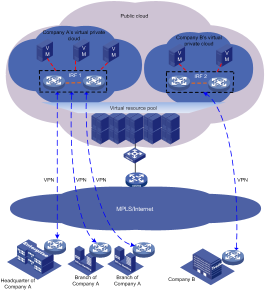
H3C Intelligent Resilient Framework (IRF) is true stacking technology that creates a large virtual stack called IRF fabric from multiple devices to provide data center class availability and scalability. This stacking technology offers processing power, interaction, unified management, and uninterrupted maintenance of multiple devices.
As shown in Figure 1, two IRF fabrics are deployed in a public cloud to provide virtual private cloud services for different tenants. The devices in each IRF fabric appear as a single node to the upper-layer and lower-layer devices.
Figure 1 IRF application scenario
IRF provides the following benefits:
· Simplified topology and easy management—An IRF fabric appears as one node and is accessible at a single IP address on the network. You can use this IP address to log in at any member device to manage all the members of the IRF fabric. In addition, you do not need to run the spanning tree feature among the IRF members.
· 1:N redundancy—In an IRF fabric, one member acts as the master to manage and control the entire IRF fabric. All the other members process services while backing up the master. When the master fails, all the other member devices elect a new master from among them to take over without interrupting services.
· Star topology—The IRF member devices are connected in star topology through a Layer 2 network. Service traffic and IRF protocol packets are delivered between member devices over existing physical links. You do not need to use dedicated physical links to connect IRF member devices.
· IRF link redundancy—You can assign several links to an IRF port for redundancy. You do not need to aggregate the links. The IRF technology removes the loop automatically.
· Network scalability and resiliency—Processing capacity of an IRF fabric equals the total processing capacities of all the members. You can add and remove IRF member devices as needed without causing network topology change.
Basic concepts
IRF member roles
IRF uses two member roles: master and standby.
When devices form an IRF fabric, they elect a master to manage and control the IRF fabric, and all the other devices back up the master. When the master device fails, the other devices automatically elect a new master. For more information about master election, see "Master election."
IRF member ID
An IRF fabric uses member IDs to uniquely identify and manage its members. This member ID information is included as the first part of interface numbers and file paths to uniquely identify interfaces and files in an IRF fabric. Two devices cannot form an IRF fabric if they use the same member ID. A device cannot join an IRF fabric if its member ID has been used in the IRF fabric.
For example, a device has an interface GigabitEthernet 1/0/1 and a file cfa0:/test.cfg. If you add the device with a member ID of 2 to an IRF fabric, the name of the interface changes to GigabitEthernet 2/0/1, and the fully qualified file name of the file changes to slot2#cfa0:/test.cfg.
IRF port
An IRF port is a logical interface that forwards data and IRF control packets between IRF member devices.
Every IRF-capable device has one IRF port. The IRF port is named irf-port n, where n is the IRF member ID of the device.
An IRF port must contain a minimum of one link to send data and control packets.
IRF links
Links of the network interfaces bound to IRF ports are called IRF links.
You can configure an IRF link as one of the following channels:
· Control channel—The link forwards only IRF control packets between member devices.
· Data channel—The link forwards only data packets between member devices.
· Hybrid channel—The link forwards both control and data packets.
For more information about network interfaces that can be used for IRF links, see "IRF port binding requirements."
Member priority
Member priority determines the possibility of a member device to be elected the master. A member with higher priority is more likely to be elected the master.
IRF topo-domain ID
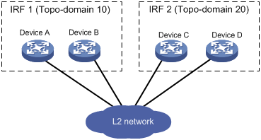
An IRF topo-domain ID uniquely identifies an IRF fabric. Devices must have the same IRF topo-domain ID to form one IRF fabric.
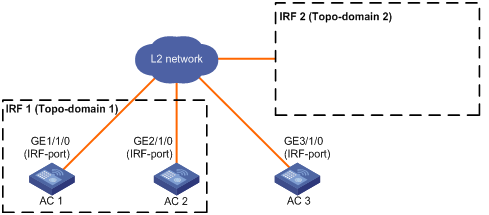
As shown in Figure 2, IRF fabric 1 contains Device A and Device B, and IRF fabric 2 contains Device C and Device D. The IRF fabrics can reach each other at Layer 2. When a member device receives a packet from an IRF link, it checks the topo-domain ID to determine whether the packet is from the local IRF fabric. Then, the member device can handle the packet correctly.
Figure 2 A network that contains two IRF topo-domains
MAD
An IRF link failure causes an IRF fabric to split in two IRF fabrics operating with the same Layer 3 settings, including the same IP address. To avoid IP address collision and network problems, IRF uses multi-active detection (MAD) mechanisms to detect the presence of multiple identical IRF fabrics, handle collisions, and recover from faults.
IRF MAD domain ID
An IRF MAD domain ID uniquely identifies an IRF MAD domain. For easy management, you can assign the same value to the IRF topo-domain ID and MAD domain ID for an IRF fabric. For more information about IRF MAD domain ID configuration, see "Configuring MAD."
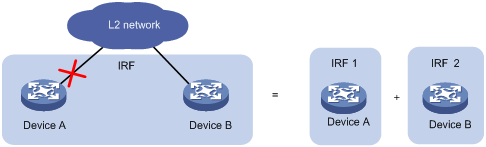
IRF split
IRF split occurs when an IRF fabric breaks up into multiple IRF fabrics when Layer 2 connectivity is lost, as shown in Figure 3. The split IRF fabrics operate with the same IP address. IRF split causes routing and forwarding problems on the network.
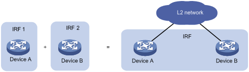
IRF merge
IRF merge occurs when two split IRF fabrics reunite or when two independent IRF fabrics are united, as shown in Figure 4.
Network topology
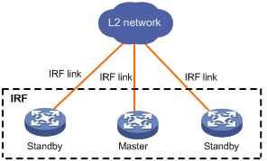
The IRF implementation of the device supports star topology. As shown in Figure 5, member devices are connected through a Layer 2 network. The member devices can communicate with one another as long as they have Layer 2 connectivity.
An IRF link can transmit IRF protocol packets, data packets, or both. For high availability, set up redundant IRF links between IRF member devices.
As a best practice to reduce data traffic across member devices, make sure the incoming and outgoing interfaces of packets for a session are on the same IRF member device.
Figure 5 Star-topology IRF fabric
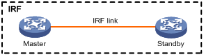
If the IRF fabric contains only two member devices, you can connect the member devices directly or through a Layer 2 network.
Figure 6 IRF fabric that contains directly connected member devices
Configuration synchronization
IRF uses a strict running-configuration synchronization mechanism. In an IRF fabric, all devices obtain and run the running configuration of the master. Configuration changes are automatically propagated from the master to the remaining devices. The configuration files of these devices are retained, but the files do not take effect. The devices use their own startup configuration files only after they are removed from the IRF fabric.
For more information about configuration management, see Fundamentals Configuration Guide.
Master election
Master election occurs each time the IRF topology changes in the following situations:
· The IRF fabric is established.
· The master device fails or is removed.
· The IRF fabric splits.
· Independent IRF fabrics merge.
Master election selects a master in the following order:
1. Current master, even if a new member has higher priority.
When an IRF fabric is being formed, all members consider themselves as the master. This rule is skipped.
2. Member with higher priority.
3. Member with the longest system uptime.
Two members are considered to start up at the same time if the difference between their startup times is equal to or less than 10 minutes. For these members, the next tiebreaker applies.
4. Member with the lowest CPU MAC address.
For the establishment of a new IRF fabric, the standby devices must reboot to join the IRF fabric after the master election.
For an IRF merge, devices must reboot if they are in the IRF fabric that fails the master election. The reboot can be performed automatically or manually.
Multi-active handling procedure
The multi-active handling procedure includes multi-active detection, collision handling, and failure recovery.
MAD detection
IRF provides MAD mechanisms by extending LACP, ARP, and IPv6 ND.
MAD identifies each IRF fabric with a MAD domain ID and an active ID (the member ID of the master). If multiple active IDs are detected in a MAD domain, MAD determines that an IRF collision or split has occurred.
For more information about the MAD mechanisms and their application scenarios, see "MAD mechanisms."
Collision handling
When detecting a multi-active collision, MAD disables all IRF fabrics except one from forwarding data traffic by placing them in Recovery state. The IRF fabrics placed in Recovery state are called inactive IRF fabrics. The IRF fabric that continues to forward traffic is called the active IRF fabric.
LACP MAD uses the following process to handle a multi-active collision:
1. Compares the number of members in each fabric.
2. Sets all fabrics to the Recovery state except the one that has the most members.
3. Compares the member IDs of the masters if all IRF fabrics have the same number of members.
4. Sets all fabrics to the Recovery state except the one that has the lowest numbered master.
5. Shuts down all network interfaces in the Recovery-state fabrics except for the following interfaces:
? IRF network interfaces.
? Interfaces configured to not shut down by using the mad exclude interface command.
In contrast, ARP MAD and ND MAD do not compare the number of members in fabrics. These MAD mechanisms use the following process to handle a multi-active collision:
1. Compare the member IDs of the masters in the IRF fabrics.
2. Set all fabrics to the Recovery state except the one that has the lowest numbered master.
3. Take the same action on the network interfaces in Recovery-state fabrics as LACP MAD.
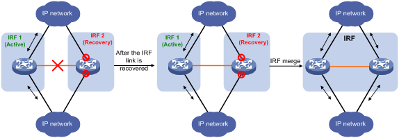
Failure recovery
When the failed IRF link between two split IRF fabrics is recovered, all member devices in the inactive IRF fabric automatically join the active IRF fabric as subordinate members. The network interfaces that have been shut down by MAD automatically restore their original state, as shown in Figure 7.
Figure 7 Recovering the IRF fabric
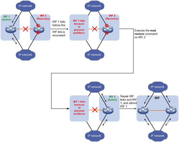
If the active IRF fabric fails before the IRF link is recovered (see Figure 8), use the mad restore command on the inactive IRF fabric to recover the inactive IRF fabric. This command brings up all network interfaces that were shut down by MAD. After the IRF link is repaired, merge the two parts into a unified IRF fabric.
Figure 8 Active IRF fabric fails before the IRF link is recovered
MAD mechanisms
As a best practice, configure a minimum of one MAD mechanism on an IRF fabric.
Do not configure LACP MAD together with ARP MAD or ND MAD, because they handle collisions differently.
Table 1 compares the MAD mechanisms and their application scenarios.
Table 1 Comparison of MAD mechanisms
|
MAD mechanism |
Advantages |
Disadvantages |
Application scenario |
|
· Detection speed is fast. · Runs on existing aggregate links without requiring MAD-dedicated physical links or Layer 3 interfaces. |
Requires an intermediate device that supports extended LACP for MAD. |
Link aggregation is used between the IRF fabric and its upstream or downstream device. For information about LACP, see Layer 2—LAN Switching Configuration Guide. |
|
|
· No intermediate device is required. · Intermediate device, if used, can come from any vendor. · Does not require MAD dedicated interfaces. |
· Detection speed is slower than LACP MAD. · The spanning tree feature must be enabled. |
Spanning tree-enabled non-link aggregation IPv4 network scenarios. For information about ARP, see Layer 3—IP Services Configuration Guide. |
|
|
· No intermediate device is required. · Intermediate device, if used, can come from any vendor. · Does not require MAD dedicated interfaces. |
· Detection speed is slower than LACP MAD. · The spanning tree feature must be enabled. |
Spanning tree-enabled non-link aggregation IPv6 network scenarios. |
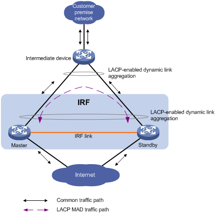
LACP MAD
As shown in Figure 9, LACP MAD has the following requirements:
· Every IRF member must have a link with an intermediate device.
· All the links form a dynamic link aggregation group.
· The intermediate device must be a device that supports extended LACP for MAD.
The IRF member devices send extended LACPDUs that convey a MAD domain ID and an active ID. The intermediate device transparently forwards the extended LACPDUs received from one member device to all the other member devices.
· If the MAD domain IDs are different, the extended LACPDU is from different IRF fabric. The device does not continue to process the packet with the MAD mechanism.
· If the MAD domain IDs and active IDs sent by all the member devices are the same, the IRF fabric is integrated.
· If the extended LACPDUs convey the same MAD domain ID but different active IDs, a split has occurred. LACP MAD handles this situation as described in "Collision handling."
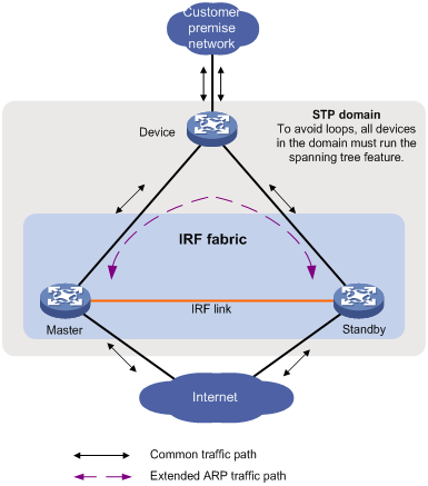
ARP MAD
ARP MAD detects multi-active collisions by using extended ARP packets that convey the IRF MAD domain ID and the active ID.
To use ARP MAD, assign the network interfaces used for ARP MAD to a VLAN interface and assign the interface an IP address. Then, enable ARP MAD on the VLAN interface.
You can set up ARP MAD links between neighbor IRF member devices, or between each IRF member device and an intermediate device (see Figure 10). If an intermediate device is used, you must also run the spanning tree feature between the IRF fabric and the intermediate device.
Each IRF member compares the MAD MAD domain ID and the active ID in incoming extended ARP packets with its MAD domain ID and active ID.
· If the MAD domain IDs are different, the extended ARP packet is from a different IRF fabric. The device does not continue to process the packet with the MAD mechanism.
· If the MAD domain IDs are the same, the device compares the active IDs.
? If the active IDs are the same, the IRF fabric is integrated.
? If the active IDs are different, the IRF fabric has split. ARP MAD handles this situation as described in "Collision handling."
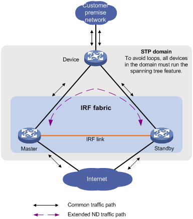
ND MAD
ND MAD detects multi-active collisions by using NS packets to transmit the IRF MAD domain ID and the active ID.
You can set up ND MAD links between neighbor IRF member devices or between each IRF member device and an intermediate device (see Figure 11). If an intermediate device is used, you must also run the spanning tree protocol between the IRF fabric and the intermediate device.
Each IRF member device compares the MAD domain ID and the active ID in incoming NS packets with its MAD domain ID and active ID.
· If the MAD domain IDs are different, the NS packet is from a different IRF fabric. The device does not continue to process the packet with the MAD mechanism.
· If the MAD domain IDs are the same, the device compares the active IDs.
? If the active IDs are the same, the IRF fabric is integrated.
? If the active IDs are different, the IRF fabric has split. ND MAD handles this situation as described in "Collision handling."
Feature and hardware compatibility
The device can form an IRF fabric only with devices of the same model.
The following matrix shows the feature and hardware compatibility:
|
Hardware series |
Model |
IRF compatibility |
|
WX1800H series |
WX1804H WX1810H WX1820H WX1840H |
No |
|
WX3800H series |
WX3820H WX3840H |
Yes |
|
WX5800H series |
WX5860H |
Yes |
General restrictions and configuration guidelines
For a successful IRF setup, follow the restrictions and guidelines in this section and the setup procedure in "Setup and configuration task list."
Software requirements
All IRF member devices must run the same software image version as the master.
For software synchronization, make sure the software auto-update feature is enabled. The feature can automatically synchronize the device with the software running on the master if the software versions are different.
You must manually synchronize the software if software auto-update fails to update software. This situation might occur if the IRF fabric cannot identify the software version used on the new device.
For more information, see "Enabling software auto-update for software image synchronization."
IRF port binding requirements
An IRF port must have a minimum of one hybrid channel, or a minimum of one data channel and one control channel.
IRF network interfaces of the same channel type must operate at the same rate.
For IRF links of an IRF port, a hybrid channel cannot coexist with a data channel or control channel. If you do not specify a channel type, the channel type of the link is hybrid. If you specify a channel type for an IRF link, you must specify a channel type for all IRF links assigned to the IRF port.
IRF transceiver module restrictions
When you select transceiver modules, follow these restrictions and guidelines:
· Do not use 100-Mbps transceiver modules for 100Base-FX SFP ports or 1000Base-X SFP ports.
· Do not use 1-Gbps transceiver modules for 10GBase-R SFP+ ports.
IRF network interface shutdown restrictions
Do not use the shutdown command on an IRF network interface if the interface is the only control channel available on the IRF standby device. If removing the channel is required, shut down the master's IRF network interfaces that have Layer 2 connectivity to that interface.
Connectivity requirements
Make sure the member devices have Layer 2 connectivity with each other.
IRF merge restrictions
If the IRF fabric splits, do not change the IRF settings on any IRF member devices before they reunite.
Feature compatibility and configuration restrictions
Link-aggregation load sharing mode restrictions
Do not configure per-packet load sharing on the Layer 2 network-side link aggregation groups that have network interfaces on multiple member devices.
NAT restrictions
NAT is not supported on an IRF fabric.
Spanning tree feature restrictions
Do not enable the spanning tree feature on any IRF network interfaces.
In the Layer 2 intermediate network, disable the spanning tree feature on the ports through which packets of an IRF member device reaches another IRF member device.
Configuration backup
As a best practice, back up the next-startup configuration file on a device before adding the device to an IRF fabric as a standby device.
A standby device's next-startup configuration file might be overwritten if the master and the standby devices use the same file name for their next-startup configuration files. You can use the backup file to restore the original configuration after removing the standby device from the IRF fabric.
IRF link removal restrictions
To remove an IRF link, you must first shut down the IRF network interfaces at the IRF link.
Setup and configuration task list
To set up an IRF fabric, perform the following tasks:
|
Tasks at a glance |
Remarks |
|
1. (Required.) Planning the IRF fabric setup |
N/A |
|
2. (Required.) Assigning the same IRF topo-domain ID to the member devices |
N/A |
|
3. (Required.) Assigning a member ID to each IRF member device |
Perform this task on each member device. |
|
4. (Optional.) Specifying a priority for each member device |
Perform this task on one or multiple member devices to affect the master election result. |
|
5. (Required.) Assigning links to an IRF port |
Perform this task on each member device. When you complete IRF port binding and activation on all IRF member devices, the IRF fabric is formed. |
|
6. (Required.) Accessing the IRF fabric |
When you log in to the IRF fabric, you are placed at the master's CLI, where you complete subsequent IRF settings and configure other features for the member devices as if they were one device. |
|
7. (Required.) Configuring MAD: ? Excluding a network interface from the shutdown action upon detection of multi-active collision |
You must configure a minimum of one MAD mechanism on an IRF fabric. Perform the following optional tasks depending on the network environment: · Excluding a network interface from the shutdown action upon detection of multi-active collision. · Recovering an IRF fabric. |
|
8. (Optional.) Enabling IRF auto-merge |
N/A |
|
9. (Optional.) Configuring a member device description |
N/A |
|
10. (Optional.) Configuring IRF bridge MAC persistence |
N/A |
|
11. (Optional.) Enabling software auto-update for software image synchronization |
H3C recommends enabling software auto-update to ensure system software image synchronization. |
|
12. (Optional.) Enabling IRF optimization for WLAN access |
N/A |
|
13. (Optional.) Maintaining the IRF memberships: |
N/A |
Planning the IRF fabric setup
Consider the following items when you plan an IRF fabric:
· Member device compatibility and restrictions.
· Fabric size.
· Master device.
· IRF network interfaces.
· Member ID and priority assignment scheme.
Assigning the same IRF topo-domain ID to the member devices
To form an IRF fabric, devices must have the same IRF topo-domain ID. IRF topo-domain IDs prevent IRF fabrics from interfering with one another.
To assign an IRF topo-domain ID to a device:
|
Step |
Command |
Remarks |
|
1. Enter system view. |
system-view |
N/A |
|
2. Assign a topo-domain ID to the device. |
irf topo-domain topo-domain-id |
The default IRF topo-domain ID is 0. For the topo-domain ID to take effect, you must reboot the device. |
Assigning a member ID to each IRF member device
|
|
CAUTION: In an IRF fabric, changing IRF member IDs might cause undesirable configuration changes and data loss. Before you do that, back up the configuration, and make sure you fully understand the impact on your network. For example, all member devices in an IRF fabric are the same model. If you swapped the IDs of any two members, their interface settings would also be swapped. |
To create an IRF fabric, you must assign a unique IRF member ID to each member device.
To prevent any undesirable configuration change or data loss, avoid changing member IDs after the IRF fabric is formed.
The new member ID takes effect at a reboot. After the device reboots, the settings on all member ID-related resources (including network interfaces) are removed, regardless of whether you have saved the configuration.
To assign a member ID to a device:
|
Step |
Command |
Remarks |
|
1. Enter system view. |
system-view |
N/A |
|
2. Assign a member ID to a member device. |
irf member member-id renumber new-member-id |
The default IRF member ID is 1. |
|
3. (Optional.) Save the configuration. |
save |
If you have bound network interfaces to IRF ports or assigned member priority, you must perform this step for these settings to take effect after the reboot. |
|
4. Reboot the device. |
reboot |
N/A |
Specifying a priority for each member device
IRF member priority represents the possibility for a device to be elected the master in an IRF fabric. The higher the priority, the higher the possibility.
A change to member priority affects the election result at the next master election, but it does not cause an immediate master re-election.
To specify a priority for a member device:
|
Step |
Command |
Remarks |
|
1. Enter system view. |
system-view |
N/A |
|
2. Specify a priority for the device. |
irf member member-id priority priority |
The default IRF member priority is 1. |
Assigning links to an IRF port
When you bind network interfaces to IRF ports, follow these guidelines:
· You can bind multiple network interfaces to an IRF port. Make sure the IRF port has a minimum of one hybrid channel, or a minimum of one data channel and one control channel.
· You must always shut down a network interface before binding it to the IRF port or removing the binding.
On the network interfaces bound to an IRF port, the default configuration is restored.
To bind network interfaces to the IRF port:
|
Step |
Command |
Remarks |
|
1. Enter system view. |
system-view |
N/A |
|
2. Enter interface view or interface range view. |
· Enter interface range view: ? Method 1: ? Method 2: · Enter interface view: |
To shut down a range of network interfaces, enter interface range view. To shut down one network interface, enter its interface view. |
|
3. Shut down the network interfaces. |
shutdown |
By default, all interfaces are up. If you cannot shut down a network interface, follow the system instruction to shut down its peer interface. |
|
4. Return to system view. |
quit |
N/A |
|
5. Enter IRF port view. |
irf-port member-id |
A device has only one IRF port. |
|
6. Bind each network interface to the IRF port. |
port group interface interface-type interface-number [ type { data | control } ] |
By default, no network interfaces are bound to an IRF port. Repeat this step to bind multiple network interfaces to the IRF port. The channel type of the link is hybrid if you do not specify a channel type. To change the channel type of an IRF link, you must first remove the binding, and then rebind its network interface to the IRF port. |
|
7. Return to system view. |
quit |
N/A |
|
8. Enter interface view or interface range view. |
· Enter interface range view: ? Method 1: ? Method 2: · Enter interface view: |
N/A |
|
9. Bring up the network interfaces. |
undo shutdown |
N/A |
|
10. Return to system view. |
quit |
N/A |
|
11. Save the configuration. |
save |
Activating IRF port configurations causes IRF merge and reboot. To avoid data loss, save the running configuration to the startup configuration file before you perform the operation. |
|
12. Activate the IRF port settings. |
irf-port-configuration active |
After this step is performed, the state of the IRF port changes to UP. The member devices elect a master, and the standby devices automatically reboot to complete the IRF establishment. After the IRF fabric is formed, you can add additional links to the IRF port (in UP state) without repeating this step. |
Accessing the IRF fabric
The IRF fabric appears as one device after it is formed. You configure and manage all IRF members from the CLI of the master. All settings you have made are propagated to the IRF members automatically.
The following methods are available for accessing an IRF fabric:
· Local login—Log in through the console port of any member device.
· Remote login—Log in at a Layer 3 interface on any member device by using methods including Telnet and SNMP.
When you log in to an IRF fabric, you are placed at the CLI of the master, regardless of at which member device you are logged in.
For more information, see login configuration in Fundamentals Configuration Guide.
Configuring MAD
General configuration restrictions and guidelines
When you configure MAD, follow these restrictions and guidelines:
· As a best practice, configure a minimum of one MAD mechanism on an IRF fabric.
· When you configure multiple MAD mechanisms, do not configure LACP MAD together with ARP MAD or ND MAD, because they handle collisions differently
· If LACP MAD, ARP MAD, or ND MAD runs between two IRF fabrics, assign each fabric a unique IRF MAD domain ID.
· An IRF fabric has only one IRF MAD domain ID. You can change the IRF MAD domain ID by using the following commands: irf domain, mad enable, mad arp enable, or mad nd enable. The IRF MAD domain IDs configured by using these commands overwrite each other.
· To prevent an interface from being shut down when the IRF fabric transits to the Recovery state, use the mad exclude interface command. To bring up interfaces in a Recovery-state IRF fabric, use the mad restore command instead of the undo shutdown command. The mad restore command activates the Recovery-state IRF fabric.
Configuring LACP MAD
Configuration restrictions and guidelines
When you use LACP MAD, follow these restrictions and guidelines:
· The intermediate device must be a device that supports extended LACP for MAD.
· If the intermediate device is also an IRF fabric, assign the two IRF fabrics different MAD domain IDs for correct split detection.
· Use dynamic link aggregation mode. MAD is LACP dependent. Even though LACP MAD can be configured on both static and dynamic aggregate interfaces, it takes effect only on dynamic aggregate interfaces.
· Configure link aggregation settings on the intermediate device.
Configuration procedure
To configure LACP MAD:
|
Step |
Command |
Remarks |
|
1. Enter system view. |
system-view |
N/A |
|
2. Assign a MAD domain ID to the IRF fabric. |
irf domain domain-id |
The default IRF MAD domain ID is 0. |
|
3. Create a Layer 2 aggregate interface and enter Layer 2 aggregate interface view. |
interface bridge-aggregation interface-number |
Perform this step also on the intermediate device. |
|
4. Configure the aggregation group to operate in dynamic aggregation mode. |
link-aggregation mode dynamic |
By default, an aggregation group operates in static aggregation mode. Perform this step also on the intermediate device. |
|
5. Enable LACP MAD. |
mad enable |
By default, LACP MAD is disabled. |
|
6. Return to system view. |
quit |
N/A |
|
7. Enter Ethernet interface view or interface range view. |
· Enter interface range view: ? Method 1: ? Method 2: · Enter Ethernet interface view: |
To assign a range of Ethernet ports to the aggregation group, enter interface range view. To assign one Ethernet port to the aggregation group, enter Ethernet interface view. |
|
8. Assign the Ethernet port or the range of Ethernet ports to the specified aggregation group. |
port link-aggregation group group-id |
Multimember link aggregation is allowed. Perform this step also on the intermediate device. |
Configuring ARP MAD
Configuration restrictions and guidelines
When you configure ARP MAD, follow these restrictions and guidelines:
|
Category |
Restrictions and guidelines |
|
ARP MAD VLAN |
· Do not enable ARP MAD on VLAN-interface 1. · If you are using intermediate devices, perform the following tasks on both the IRF fabric and the intermediate devices: ? Create a VLAN and VLAN interface for ARP MAD. ? Assign the ports of ARP MAD links to the ARP MAD VLAN. · As a best practice, do not use the ARP MAD VLAN for any other purposes. |
|
ARP MAD and feature configuration |
If intermediate devices are used, make sure the following requirements are met: · Run the spanning tree feature between the IRF fabric and the intermediate devices to ensure that there is only one ARP MAD path in forwarding state. For more information about the spanning tree feature and its configuration, see Layer 2—LAN Switching Configuration Guide. · Enable the IRF fabric to change its bridge MAC address as soon as the address owner leaves. · If an intermediate device is also an IRF fabric, assign the two IRF fabrics different MAD domain IDs for correct split detection. |
Configuration procedure
To configure ARP MAD:
|
Step |
Command |
Remarks |
|
1. Enter system view. |
system-view |
N/A |
|
2. Assign a MAD domain ID to the IRF fabric. |
irf domain domain-id |
The default IRF MAD domain ID is 0. |
|
3. Configure the IRF bridge MAC address to change as soon as the address owner leaves. |
undo irf mac-address persistent |
By default, the IRF bridge MAC address remains unchanged for 6 minutes after the address owner leaves. |
|
4. Create a VLAN dedicated to ARP MAD. |
vlan vlan-id |
By default, only VLAN 1 exists. |
|
5. Return to system view. |
quit |
N/A |
|
6. Enter Ethernet interface view or interface range view. |
· Enter interface range view: ? Method 1: ? Method 2: · Enter interface view: |
To assign a range of ports to the ARP MAD VLAN, enter interface range view. To assign one port to the ARP MAD VLAN, enter Ethernet interface view. |
|
7. Assign the port or the range of ports to the ARP MAD VLAN. |
· Assign the port to the VLAN as an access port:
· Assign the port to the VLAN as a trunk port: · Assign the port to the VLAN as a hybrid
port: |
The link type of ARP MAD ports can be access, trunk, or hybrid. The default link type of a port is access. |
|
8. Return to system view. |
quit |
N/A |
|
9. Enter VLAN interface view. |
interface vlan-interface vlan-interface-id |
N/A |
|
10. Assign the interface an IP address. |
ip address ip-address { mask | mask-length } |
By default, no IP addresses are assigned to any VLAN interfaces. |
|
11. Enable ARP MAD. |
mad arp enable |
By default, ARP MAD is disabled. |
Configuring ND MAD
Configuration restrictions and guidelines
When you use ND MAD, follow these guidelines:
· Do not configure ND MAD on VLAN-interface 1.
· Do not use the VLAN configured for ND MAD for any other purposes.
· If an intermediate device is used, you can use common data links as ND MAD links. If no intermediate device is used, set up dedicated ND MAD links between IRF member devices.
· If an intermediate device is used, make sure the following requirements are met:
? Run the spanning tree feature between the IRF fabric and the intermediate device. Make sure there is only one ND MAD link in forwarding state. For more information about the spanning tree feature and its configuration, see Layer 2—LAN Switching Configuration Guide.
? Enable the IRF fabric to change its bridge MAC address as soon as the address owner leaves.
? Create an ND MAD VLAN and assign the ports on the ND MAD links to the VLAN.
? If the intermediate device is also an IRF fabric, assign the two IRF fabrics different MAD domain IDs for correct split detection.
Configuration procedure
To configure ND MAD:
|
Step |
Command |
Remarks |
|
1. Enter system view. |
system-view |
N/A |
|
2. Assign a MAD domain ID to the IRF fabric. |
irf domain domain-id |
The default IRF MAD domain ID is 0. |
|
3. Configure the IRF bridge MAC address to change as soon as the address owner leaves. |
undo irf mac-address persistent |
By default, the IRF bridge MAC address remains unchanged for 6 minutes after the address owner leaves. |
|
4. Create a VLAN dedicated to ND MAD. |
vlan vlan-id |
By default, only VLAN 1 exists. |
|
5. Return to system view. |
quit |
N/A |
|
6. Enter Ethernet interface view. |
interface interface-type interface-number |
N/A |
|
7. Assign the port to the ND MAD VLAN. |
· Assign the port to the VLAN as an access port:
· Assign the port to the VLAN as a trunk port: · Assign the port to the VLAN as a hybrid
port: |
The link type of ND MAD ports can be access, trunk, or hybrid. The default link type of a port is access. |
|
8. Return to system view. |
quit |
N/A |
|
9. Enter VLAN interface view. |
interface vlan-interface vlan-interface-id |
N/A |
|
10. Assign the interface an IP address. |
ipv6 address { ipv6-address/prefix-length | ipv6-address prefix-length } |
By default, no IPv6 addresses are assigned to a VLAN interfaces. |
|
11. Enable ND MAD. |
mad nd enable |
By default, ND MAD is disabled. |
Excluding a network interface from the shutdown action upon detection of multi-active collision
By default, all interfaces except the IRF network interfaces and the console port shut down automatically when the IRF fabric transits to the Recovery state.
You can exclude a network interface from the shutdown action for management or other special purposes. For example:
· Exclude an interface from the shutdown action so you can Telnet to the interface for managing the device.
· Exclude a VLAN interface and its Layer 2 Ethernet ports from the shutdown action so you can log in through the VLAN interface.
Configuration restrictions and guidelines
When you configure this feature, follow these restrictions and guidelines:
· If the Layer 2 Ethernet ports of a VLAN interface are distributed on multiple member devices, the exclusion operation might introduce IP collision risks. The VLAN interface might be up on both active and inactive IRF fabrics.
· Do not exclude aggregate interfaces used for MAD and their member interfaces from the shutdown action.
Configuration procedure
To configure a network interface to not shut down when the IRF fabric transits to the Recovery state:
|
Step |
Command |
Remarks |
|
1. Enter system view. |
system-view |
N/A |
|
2. Configure a network interface to not shut down when the IRF fabric transits to the Recovery state. |
mad exclude interface interface-type interface-number |
By default, all interfaces on a Recovery-state IRF fabric are shut down, except for the IRF network interfaces and console port. |
Recovering an IRF fabric
If the active IRF fabric fails before the IRF link is recovered, perform this task on the inactive IRF fabric to recover the inactive IRF fabric for traffic forwarding. The manual recovery operation brings up all network interfaces that were shut down by MAD on the inactive IRF fabric.
To manually recover an inactive IRF fabric:
|
Step |
Command |
|
1. Enter system view. |
system-view |
|
2. Recover the inactive IRF fabric. |
mad restore |
Enabling IRF auto-merge
When two IRF fabrics merge, a member device must reboot to complete the merge if it is in the IRF fabric that fails in master election.
· If the auto-merge feature is enabled, the reboot is automatically performed.
· If the auto-merge feature is disabled, you must reboot the member device manually.
This feature works only when it is enabled on both IRF fabrics that are merging.
To enable IRF auto-merge:
|
Step |
Command |
Remarks |
|
1. Enter system view. |
system-view |
N/A |
|
2. Enable IRF auto-merge. |
irf auto-merge enable |
By default, this feature is enabled. |
Configuring a member device description
|
Step |
Command |
Remarks |
|
1. Enter system view. |
system-view |
N/A |
|
2. Configure a description for a member device. |
irf member member-id description text |
By default, no member device description is configured. |
Configuring IRF bridge MAC persistence
Overview
By default, an IRF fabric uses the bridge MAC address of the master device as its bridge MAC address. Layer 2 protocols, such as LACP, use this bridge MAC address to identify the IRF fabric. On a switched LAN, the bridge MAC address must be unique.
To avoid duplicate bridge MAC addresses, an IRF fabric can change its bridge MAC address automatically after the address owner leaves. However, the change causes temporary traffic disruption.
Depending on the network condition, enable the IRF fabric to retain or change its bridge MAC address after the address owner leaves. Available options include:
· irf mac-address persistent timer—Bridge MAC address of the IRF fabric is retained for 6 minutes after the address owner leaves. If the address owner does not return before the timer expires, the IRF fabric uses the bridge MAC address of the current master as its bridge MAC address. This option avoids unnecessary bridge MAC address changes caused by device reboot, transient link failure, or purposeful link disconnection.
· irf mac-address persistent always—Bridge MAC address of the IRF fabric does not change after the address owner leaves.
· undo irf mac-address persistent—Bridge MAC address of the current master replaces the original IRF bridge MAC address as soon as the owner of the original address leaves.
Configuration restrictions and guidelines
When IRF fabrics merge, IRF ignores the IRF bridge MAC address and checks the bridge MAC address of each member device in the IRF fabrics. IRF merge fails if any two member devices have the same bridge MAC address.
If ARP MAD or ND MAD is used, you must disable IRF bridge MAC persistence by using the undo irf mac-address persistent command.
Configuration procedure
To configure the IRF bridge MAC persistence setting:
|
Step |
Command |
Remarks |
|
1. Enter system view. |
system-view |
N/A |
|
2. Configure IRF bridge MAC persistence. |
· Retain the
bridge MAC address even if the address owner has left
the IRF fabric: · Retain the
bridge MAC address for 6 minutes after the address
owner leaves the IRF fabric: · Change the bridge MAC address as soon
as the address owner leaves the IRF fabric: |
By default, the IRF bridge MAC address remains unchanged for 6 minutes after the address owner leaves the IRF fabric. |
Enabling software auto-update for software image synchronization
|
|
IMPORTANT: To ensure a successful software auto-update in a multi-user environment, prevent anyone from rebooting member devices during the auto-update process. To inform administrators of the auto-update status, configure the information center to output the status messages to configuration terminals (see Network Management and Monitoring Configuration Guide). |
The software auto-update feature automatically synchronizes the current software images of the master to devices that are attempting to join the IRF fabric.
To join an IRF fabric, a device must use the same software images as the master in the IRF fabric.
When you add a device to the IRF fabric, software auto-update compares the startup software images of the device with the current software images of the IRF master. If the two sets of images are different, the device automatically performs the following tasks:
1. Downloads the current software images of the master.
2. Sets the downloaded images as its main startup software images.
3. Reboots with the new software images to rejoin the IRF fabric.
You must manually update the new device with the software images running on the IRF fabric in the following situations:
· Software auto-update is disabled.
· Software auto-update fails to update software. This situation might occur if the IRF fabric cannot identify the software version used on the new device.
Configuration prerequisites
Make sure the device you are adding to the IRF fabric has sufficient storage space for the new software images.
If sufficient storage space is not available, the device automatically deletes the current software images. If the reclaimed space is still insufficient, the device cannot complete the auto-update. You must reboot the device, and then access the Boot ROM menu to delete files.
Configuration procedure
To enable automatic software synchronization with the master:
|
Step |
Command |
Remarks |
|
1. Enter system view. |
system-view |
N/A |
|
2. Enable software auto-update. |
irf auto-update enable |
By default, software auto-update is enabled. |
Enabling IRF optimization for WLAN access
Use this feature to guarantee reliable AP and client access. This feature accelerates IRF master election, new member joining, and IRF member role change to prevent IRF events from causing unstable AP or client access.
To enable IRF optimization for WLAN access:
|
Step |
Command |
Remarks |
|
1. Enter system view. |
system-view |
N/A |
|
2. Enable IRF optimization for WLAN access. |
irf-optimize wlan reliable-access |
By default, WLAN access optimization is enabled in an IRF fabric. |
Maintaining the IRF memberships
For troubleshooting or maintenance purposes, you can remove a member device from an IRF fabric by disabling the member device's multimember stacking capability. The removed member device still runs the original IRF settings. However, it does not send or receive IRF control packets.
After you finish the troubleshooting or maintenance tasks, you can enable the member device's multimember stacking capability to add the device back to the IRF fabric.
Removing a device from the IRF fabric
The removed IRF member might have the same Layer 2 or Layer 3 settings as the IRF fabric. For example, the IP address and bridge MAC address. To avoid network collisions, change these settings on the removed member or on the IRF fabric.
To remove a member device from the IRF fabric by disabling the member device's multimember stacking capability:
|
Step |
Command |
Remarks |
|
1. Enter system view. |
system-view |
N/A |
|
2. Disable multimember stacking capability for a member device. |
undo irf member member-id stack enable |
By default, multimember stacking capability is enabled for an IRF member device. The device will be removed from the IRF fabric 5 seconds after you execute this command. |
Adding a removed member device back to the IRF fabric
To add a removed member device back to the original IRF fabric or to a new IRF fabric, you must enable the device's multimember stacking capability.
To enable multimember stacking capability for a device:
|
Step |
Command |
|
1. Log in to the removed device. |
N/A |
|
2. Enable multimember stacking capability for the device. |
irf member member-id stack enable |
|
3. Return to user view. |
quit |
|
4. Save the running configuration. |
save |
|
5. Reboot the device for the setting to take effect. |
reboot |
Displaying and maintaining an IRF fabric
Execute display commands in any view.
|
Task |
Command |
|
Display information about all IRF members. |
display irf |
|
Display information about the IRF hello packets sent and received on a member device. |
display irf forwarding [ slot slot-number ] |
|
Display IRF link information. |
display irf link |
|
Display the IRF configuration. |
display irf configuration |
|
Display MAD configuration. |
display mad [ verbose ] |
Configuration examples
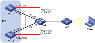
LACP MAD-enabled IRF configuration example
Network requirements
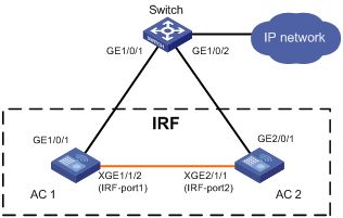
As shown in Figure 12, connect AC 1 and AC 2 through a Layer 2 switch to set up a star-topology IRF fabric. Configure LACP MAD on the dynamic aggregation to the switch, an H3C device that supports extended LACP.
Configuration procedure
1. Configure the switch:
# Create VLAN 400, and assign Ten-GigabitEthernet 1/0/25 and Ten-GigabitEthernet 1/0/26 to the VLAN for IRF links.
<Switch> system-view
[Switch] vlan 400
[Switch-vlan400] port ten-gigabitethernet 1/0/25
[Switch-vlan400] port ten-gigabitethernet 1/0/26
[Switch-vlan400] quit
# Disable the spanning tree feature on Ten-GigabitEthernet 1/0/25 and Ten-GigabitEthernet 1/0/26.
[Switch] interface ten-gigabitethernet 1/0/25
[Switch-Ten-GigabitEthernet1/0/25] undo stp enable
[Switch-Ten-GigabitEthernet1/0/25] quit
[Switch] interface ten-gigabitethernet 1/0/26
[Switch-Ten-GigabitEthernet1/0/26] undo stp enable
[Switch-Ten-GigabitEthernet1/0/26] quit
# Create Bridge Aggregation 1, and configure Layer 2 aggregation group 1 to operate in dynamic aggregation mode.
[Switch] interface bridge-aggregation 1
[Switch-Bridge-Aggregation1] link-aggregation mode dynamic
[Switch-Bridge-Aggregation1] quit
# Enable link-aggregation traffic redirection.
[Switch] link-aggregation lacp traffic-redirect-notification enable
# Add GigabitEthernet 1/0/1 to aggregation group 1.
[Switch] interface gigabitethernet 1/0/1
[Switch-GigabitEthernet1/0/1] port link-aggregation group 1
[Switch-GigabitEthernet1/0/1] quit
# Add GigabitEthernet 1/0/2 to aggregation group 1.
[Switch] interface gigabitethernet 1/0/2
[Switch-GigabitEthernet1/0/2] port link-aggregation group 1
[Switch-GigabitEthernet1/0/2] quit
# Create VLAN 100, and add Bridge Aggregation 1, GigabitEthernet 1/0/1, and GigabitEthernet 1/0/2 to the VLAN.
[Switch] vlan 100
[Switch-vlan100] port bridge-aggregation 1
[Switch-vlan100] port gigabitethernet 1/0/1
[Switch-vlan100] port gigabitethernet 1/0/2
[Switch-vlan100] quit
2. Configure AC 1:
# Bind Ten-GigabitEthernet 1/0/25 to the IRF port.
<AC1> system-view
[AC1] interface ten-gigabitethernet 1/0/25
[AC1-Ten-GigabitEthernet1/0/25] shutdown
[AC1-Ten-GigabitEthernet1/0/25] quit
[AC1] irf-port 1
[AC1-irf-port1] port group interface ten-gigabitethernet 1/0/25
[AC1-irf-port1] quit
[AC1] interface ten-gigabitethernet 1/0/25
[AC1-Ten-GigabitEthernet1/0/25] undo shutdown
[AC1-Ten-GigabitEthernet1/0/25] quit
# Assign IRF member priority 2 to AC 1 for AC 1 to win the master election.
[AC1] irf member 1 priority 2
# Save the configuration and activate the IRF port configuration.
[AC1] save
The current configuration will be written to the device. Are you sure? [Y/N]:y
Please input the file name(*.cfg)[cfa0:/startup.cfg]
(To leave the existing filename unchanged, press the enter key):
Validating file. Please wait...
Saved the current configuration to mainboard device successfully.
[AC1] irf-port-configuration active
3. Configure AC 2:
# Assign member ID 2 to AC 2 and reboot AC 2 for the configuration to take effect.
<AC2> system-view
[AC2] irf member 1 renumber 2
Renumbering the member ID may result in configuration change or loss. Continue?[
Y/N]:y
[AC2] quit
<AC2> reboot
Start to check configuration with next startup configuration file, please wait..
.......DONE!
Current configuration may be lost after the reboot, save current configuration?
[Y/N]:y
Please input the file name(*.cfg)[cfa0:/startup.cfg]
(To leave the existing filename unchanged, press the enter key):
cfa0:/startup.cfg exists, overwrite? [Y/N]:y
Validating file. Please wait...
Saved the current configuration to mainboard device successfully.
This command will reboot the device. Continue? [Y/N]:y
Now rebooting, please wait...
# Bind Ten-GigabitEthernet 2/0/25 to the IRF port.
<AC2> system-view
[AC2] interface ten-gigabitethernet 2/0/25
[AC2-Ten-GigabitEthernet2/0/25] shutdown
[AC2-Ten-GigabitEthernet2/0/25] quit
[AC2] irf-port 2
[AC2-irf-port2] port group interface ten-gigabitethernet 2/0/25
[AC2-irf-port2] quit
[AC2] interface ten-gigabitethernet 2/0/25
[AC2-Ten-GigabitEthernet2/0/25] undo shutdown
[AC2-Ten-GigabitEthernet2/0/25] quit
# Save the configuration and activate the IRF port configuration.
[AC2] save
The current configuration will be written to the device. Are you sure? [Y/N]:y
Please input the file name(*.cfg)[cfa0:/startup.cfg]
(To leave the existing filename unchanged, press the enter key):
Validating file. Please wait...
Saved the current configuration to mainboard device successfully.
[AC2] irf-port-configuration active
# AC 1 and AC 2 perform master election. AC 2 fails the master election and reboots to form an IRF fabric with AC 1.
4. Configure the IRF fabric:
# Change the system name to IRF.
<AC1> system-view
[AC1] system-name IRF
# Configure the description as AC 1 for IRF member 1 and AC 2 for IRF member 2.
[IRF] irf member 1 description AC 1
[IRF] irf member 2 description AC 2
# Create Bridge Aggregation 1, and configure Layer 2 aggregation group 1 to operate in dynamic aggregation mode.
[IRF] interface bridge-aggregation 1
[IRF-Bridge-Aggregation1] link-aggregation mode dynamic
# Enable LACP MAD.
[IRF-Bridge-Aggregation1] mad enable
[IRF-Bridge-Aggregation1] quit
# Enable link-aggregation traffic redirection.
[IRF] link-aggregation lacp traffic-redirect-notification enable
# Add GigabitEthernet 1/0/1 to aggregation group 1.
[IRF] interface gigabitethernet 1/0/1
[IRF-GigabitEthernet1/0/1] port link-aggregation group 1
[IRF-GigabitEthernet1/0/1] quit
# Add GigabitEthernet 2/0/1 to aggregation group 1.
[IRF] interface gigabitethernet 2/0/1
[IRF-GigabitEthernet2/0/1] port link-aggregation group 1
[IRF-GigabitEthernet2/0/1] quit
# Create VLAN 100, and add Bridge Aggregation 1, GigabitEthernet 1/0/1, and GigabitEthernet 2/0/1 to the VLAN for service traffic.
<IRF> system-view
[IRF] vlan 100
[IRF-vlan100] port bridge-aggregation 1
[IRF-vlan100] port gigabitethernet 1/0/1
[IRF-vlan100] port gigabitethernet 2/0/1
[IRF-vlan100] quit
Verifying the configuration
# Display IRF fabric information on the IRF fabric. Verify that AC 1 is the master.
[IRF] display irf
Member ID Role Priority CPU MAC Description
*1 Master 2 50da-0051-2608 AC 1
+2 Standby 1 50da-0051-2670 AC 2
--------------------------------------------------
The asterisk (*) indicates the master.
The plus sign (+) indicates the device through which you are logged in.
The right angle bracket (>) indicates the device's stack capability is disabled.
Bridge MAC of the IRF: 50da-0051-2608
Auto upgrade : Enabled
MAC persistence : 6 min
Topo-domain ID : 0
Auto merge : Enabled
# Display IRF link information to verify that both IRF ports are up.
[IRF] display irf link
Member ID Member Interfaces Status
1 XGE1/0/25(ctrl&data) Up
2 XGE2/0/25(ctrl&data) Up
# Display detailed information about aggregation group 1 on the IRF fabric. Verify that GigabitEthernet 1/0/1 and GigabitEthernet 2/0/1 are assigned to Bridge-Aggregation 1 and are in Selected state.
[IRF] display link-aggregation verbose
Loadsharing Type: Shar -- Loadsharing, NonS -- Non-Loadsharing
Port Status: S -- Selected, U -- Unselected, I -- Individual
Flags: A -- LACP_Activity, B -- LACP_Timeout, C -- Aggregation,
D -- Synchronization, E -- Collecting, F -- Distributing,
G -- Defaulted, H -- Expired
Aggregate Interface: Bridge-Aggregation1
Aggregation Mode: Dynamic
Loadsharing Type: Shar
System ID: 0x8000, 50da-0051-2608
Local:
Port Status Priority Oper-Key Flag
--------------------------------------------------------------------------------
GE1/0/1 S 32768 1 {ACDEF}
GE2/0/1 S 32768 1 {ACDEF}
Remote:
Actor Partner Priority Oper-Key SystemID Flag
--------------------------------------------------------------------------------
GE1/0/1 1 32768 1 0x8000, 3897-d633-f3c6 {ACDEF}
GE2/0/1 2 32768 1 0x8000, 3897-d633-f3c6 {ACDEF}
# Display detailed information about aggregation group 1 on the switch. Verify that GigabitEthernet 1/0/1 and GigabitEthernet 1/0/2 are assigned to Bridge-Aggregation 1 and are in Selected state.
[Switch] display link-aggregation verbose
Loadsharing Type: Shar -- Loadsharing, NonS -- Non-Loadsharing
Port Status: S -- Selected, U -- Unselected,
I -- Individual, * -- Management port
Flags: A -- LACP_Activity, B -- LACP_Timeout, C -- Aggregation,
D -- Synchronization, E -- Collecting, F -- Distributing,
G -- Defaulted, H -- Expired
Aggregate Interface: Bridge-Aggregation1
Aggregation Mode: Dynamic
Loadsharing Type: Shar
Management VLAN : None
System ID: 0x8000, 3897-d633-f3c6
Local:
Port Status Priority Oper-Key Flag
--------------------------------------------------------------------------------
GE1/0/1 S 32768 1 {ACDEF}
GE1/0/2 S 32768 1 {ACDEF}
Remote:
Actor Partner Priority Oper-Key SystemID Flag
--------------------------------------------------------------------------------
GE1/0/1 2 32768 1 0x8000, 50da-0051-2608 {ACDEF}
GE1/0/2 31 32768 1 0x8000, 50da-0051-2608 {ACDEF}
ARP MAD-enabled IRF configuration example
Network requirements
As shown in Figure 13, use AC 1 and AC 2 to set up a two-member IRF fabric.
· Configure ARP MAD for the IRF fabric and use the switch as the intermediate device.
· To prevent loops, enable the spanning tree feature between the IRF fabric and the switch.
Configuration procedure
1. Configure AC 1:
# Bind Ten-GigabitEthernet 1/1/2 to the IRF port and save the configuration.
<AC1> system-view
[AC1] interface ten-gigabitethernet 1/1/2
[AC1-Ten-GigabitEthernet1/1/2] shutdown
[AC1-Ten-GigabitEthernet1/1/2] quit
[AC1] irf-port 1
[AC1-irf-port1] port group interface ten-gigabitethernet 1/1/2
[AC1-irf-port1] quit
[AC1] interface ten-gigabitethernet 1/1/2
[AC1-Ten-GigabitEthernet1/1/2] undo shutdown
[AC1-Ten-GigabitEthernet1/1/2] quit
[AC1] save
# Activate the IRF port configuration.
[AC1] irf-port-configuration active
2. Configure AC 2:
# Change the member ID of AC 2 from 1 to 2, and reboot AC 2 for the new member ID to take effect.
<AC2> system-view
[AC2] irf member 1 renumber 2
Warning: Renumbering the member ID may result in configuration change or loss. Continue? [Y/N]:y
[AC2] quit
<AC2> reboot
# Connect AC 1 and AC 2 as shown in Figure 13. (Details not shown.)
# Log in to AC 2. (Details not shown.)
# Bind Ten-GigabitEthernet 2/1/1 to the IRF port and save the configuration.
<AC2> system-view
[AC2] interface ten-gigabitethernet 2/1/1
[AC2-Ten-GigabitEthernet2/1/1] shutdown
[AC2-Ten-GigabitEthernet2/1/1] quit
[AC2] irf-port 2
[AC2-irf-port2] port group interface ten-gigabitethernet 2/1/1
[AC2-irf-port2] quit
[AC2] interface ten-gigabitethernet 2/1/1
[AC2-Ten-GigabitEthernet2/1/1] undo shutdown
[AC2-Ten-GigabitEthernet2/1/1] quit
[AC2] save
# Activate the IRF port configuration.
[AC2] irf-port-configuration active
3. AC 1 and AC 2 perform master elction. The device that fails the master election will reboot to form an IRF fabric with the other device.
4. Configure ARP MAD on the IRF fabric:
# Enable the spanning tree feature globally, and map the ARP MAD VLAN to MSTI 1 in the MST region.
<AC1> system-view
[AC1] stp global enable
[AC1] stp region-configuration
[AC1-mst-region] region-name arpmad
[AC1-mst-region] instance 1 vlan 3
[AC1-mst-region] active region-configuration
[AC1-mst-region] quit
# Configure the bridge MAC address of the IRF fabric to change as soon as the address owner leaves.
[AC1] undo irf mac-address persistent
# Set the MAD domain ID of the IRF fabric to 1.
[AC1] irf domain 1
# Create VLAN 3, and add GigabitEthernet 1/0/1 on AC 1 (member ID 1) and GigabitEthernet 2/0/1 on AC 2 (member ID 2) to VLAN 3.
[AC1] vlan 3
[AC1-vlan3] port gigabitethernet 1/0/1 gigabitethernet 2/0/1
[AC1-vlan3] quit
# Create VLAN-interface 3, assign it an IP address, and enable ARP MAD on the interface.
[AC1] interface vlan-interface 3
[AC1-Vlan-interface3] ip address 192.168.2.1 24
[AC1-Vlan-interface3] mad arp enable
You need to assign a domain ID (range: 0-4294967295)
[Current domain is: 1]:
The assigned domain ID is: 1
5. Configure the switch as the intermediate device:
|
|
CAUTION: If the intermediate device is also an IRF fabric, assign the two IRF fabrics different MAD domain IDs for correct split detection. False detection causes IRF split. |
# Enable the spanning tree feature globally, and map the ARP MAD VLAN to MSTI 1 in the MST region.
<Switch> system-view
[Switch] stp global enable
[Switch] stp region-configuration
[Switch-mst-region] region-name arpmad
[Switch-mst-region] instance 1 vlan 3
[Switch-mst-region] active region-configuration
[Switch-mst-region] quit
# Create VLAN 3, and add GigabitEthernet1/0/1 and GigabitEthernet1/0/2 to VLAN 3.
[Switch] vlan 3
[Switch-vlan3] port gigabitethernet 1/0/1 gigabitethernet 1/0/2
[Switch-vlan3] quit
ND MAD-enabled IRF configuration example
Network requirements
As shown in Figure 14, use AC 1 and AC 2 to set up a two-member IRF fabric.
· Configure ND MAD for the IRF fabric and use the switch as the intermediate device.
· To prevent loops, enable the spanning tree feature between the IRF fabric and the switch.
Configuration procedure
1. Configure AC 1:
# Bind Ten-GigabitEthernet 1/1/2 to the IRF port and save the configuration.
<AC1> system-view
[AC1] interface ten-gigabitethernet 1/1/2
[AC1-Ten-GigabitEthernet1/1/2] shutdown
[AC1-Ten-GigabitEthernet1/1/2] quit
[AC1] irf-port 1
[AC1-irf-port1] port group interface ten-gigabitethernet 1/1/2
[AC1-irf-port1] quit
[AC1] interface ten-gigabitethernet 1/1/2
[AC1-Ten-GigabitEthernet1/1/2] undo shutdown
[AC1-Ten-GigabitEthernet1/1/2] quit
[AC1] save
# Activate the IRF port configuration.
[AC1] irf-port-configuration active
2. Configure AC 2:
# Change the member ID 2 of AC 2 from 1 to 2, and reboot AC 2 for the new member ID to take effect.
<AC2> system-view
[AC2] irf member 1 renumber 2
Warning: Renumbering the member ID may result in configuration change or loss. Continue? [Y/N]:y
[AC2] quit
<AC2> reboot
# Connect AC 1 and AC 2 as shown in Figure 14. (Details not shown.)
# Log in to AC 2. (Details not shown.)
# Bind Ten-GigabitEthernet 2/1/1 to the IRF port and save the configuration.
<AC2> system-view
[AC2] interface ten-gigabitethernet 2/1/1
[AC2-Ten-GigabitEthernet2/1/1] shutdown
[AC2-Ten-GigabitEthernet2/1/1] quit
[AC2] irf-port 2
[AC2-irf-port2] port group interface ten-gigabitethernet 2/1/1
[AC2-irf-port2] quit
[AC2] interface ten-gigabitethernet 2/1/1
[AC2-Ten-GigabitEthernet2/1/1] undo shutdown
[AC2-Ten-GigabitEthernet2/1/1] quit
[AC2] save
# Activate the IRF port configuration.
[AC2] irf-port-configuration active
3. AC 1 and AC 2 perform master elction. The device that fails the master election will reboot to form an IRF fabric with the other device.
4. Configure ND MAD on the IRF fabric:
# Enable the spanning tree feature globally, and map the ND MAD VLAN to MSTI 1 in the MST region.
<AC1> system-view
[AC1] stp global enable
[AC1] stp region-configuration
[AC1-mst-region] region-name ndmad
[AC1-mst-region] instance 1 vlan 3
[AC1-mst-region] active region-configuration
[AC1-mst-region] quit
# Configure the bridge MAC address of the IRF fabric to change as soon as the address owner leaves.
[AC1] undo irf mac-address persistent
# Set the domain ID of the IRF fabric to 1.
[AC1] irf domain 1
# Create VLAN 3, and add GigabitEthernet 1/0/1 on AC 1 (member ID 1) and GigabitEthernet 2/0/1 on AC 2 (member ID 1) to VLAN 3.
[AC1] vlan 3
[AC1-vlan3] port gigabitethernet 1/0/1 gigabitethernet 2/0/1
[AC1-vlan3] quit
# Create VLAN-interface 3, assign it an IPv6 address, and enable ND MAD on the interface.
[AC1] interface vlan-interface 3
[AC1-Vlan-interface3] ipv6 address 2001::1 64
[AC1-Vlan-interface3] mad nd enable
You need to assign a domain ID (range: 0-4294967295)
[Current domain is: 1]:
The assigned domain ID is: 1
5. Configure the switch as the intermediate device:
|
|
CAUTION: If the intermediate device is also an IRF fabric, assign the two IRF fabrics different MAD domain IDs for correct split detection. False detection causes IRF split. |
# Enable the spanning tree feature globally, and map the ND MAD VLAN to MSTI 1 in the MST region.
<Switch> system-view
[Switch] stp global enable
[Switch] stp region-configuration
[Switch-mst-region] region-name ndmad
[Switch-mst-region] instance 1 vlan 3
[Switch-mst-region] active region-configuration
[Switch-mst-region] quit
# Create VLAN 3, and add GigabitEthernet 1/0/1 and GigabitEthernet 1/0/2 to VLAN 3.
[Switch] vlan 3
[Switch-vlan3] port gigabitethernet 1/0/1 gigabitethernet 1/0/2
[Switch-vlan3] quit
Member device migration example
Network requirements
As shown in Figure 15, migrate AC 3 from IRF 1 to IRF 2.
Configuration procedure
1. Configure IRF 1:
# Log in to IRF 1 and identify the member ID of AC 3.
<Sysname> display irf
Member ID Role Priority CPU MAC Description
*+1 Master 2 000c-298f-04bb ---
2 Standby 1 000c-2925-4ae1 ---
3 Standby 1 000c-2925-4ae2 ---
---------------------------------------------------
The asterisk (*) indicates the master.
The plus sign (+) indicates the device through which you are logged in.
The right angle bracket (>) indicates the device's stack capability is disabled.
Bridge MAC of the IRF: 7425-8ae3-f48f
Auto upgrade : Enabled
MAC persistence : 6 min
Topo-domain ID : 0
Auto merge : Enabled
# Remove AC 3 from IRF 1.
<Sysname> system-view
[Sysname] undo irf member 3 stack enable
Member 3 will leave from the IRF and cannot form an IRF with any other devices. Continue? [Y/N]: Y
Operation succeeded. Please check the configuration on member 3 with the IRF for configuration collisions.
2. Configure AC 3:
# Log in to AC 3 and change its IRF topo-domain ID to 2.
<Sysname> system-view
[Sysname] irf topo-domain 2
The configuration will take effect at the next startup.
# Add AC 3 to IRF 2.
<Sysname> system-view
[Sysname] irf member 3 stack enable
Please save the configuration, and then reboot the device for the configuration to take effect.
[Sysname] quit
<Sysname> reboot
Start to check configuration with next startup configuration file, please wait..
.......DONE!
Current configuration may be lost after the reboot, save current configuration?
[Y/N]:y
Please input the file name(*.cfg)[cfa0:/startup.cfg]
(To leave the existing filename unchanged, press the enter key):
cfa0:/startup.cfg exists, overwrite? [Y/N]:y
Validating file. Please wait...
Saved the current configuration to mainboard device successfully.
This command will reboot the device. Continue? [Y/N]:y
Verifying the configuration
# Log in to IRF 2. (Details not shown.)
# Verify that AC 3 has joined IRF 2.
<Sysname> display irf
A
access
IRF WLAN access optimization, 25
accessing
IRF fabric, 17
adding
IRF member, 25
application
IRF fabric ARP MAD application scenario, 9
IRF fabric LACP MAD application scenario, 8
IRF fabric ND MAD application scenario, 10
ARP
MAD. See ARP MAD
IRF ARP MAD configuration, 19
IRF fabric ARP MAD, 9
IRF fabric ARP MAD configuration, 31
assigning
IRF device member ID, 15
IRF topo-domain ID, 14
auto
IRF auto-merge, 22
IRF software auto-update, 24
B
backing up
IRF configuration backup, 13
binding
IRF network interface+port, 15
C
CLI
IRF fabric access CLI login, 17
collision handling (IRF), 5
compatibility
IRF and hardware, 11
configuring
IRF, 26
IRF ARP MAD, 19
IRF bridge MAC address, 23
IRF fabric, 13
IRF fabric ARP MAD, 31
IRF fabric LACP MAD, 26
IRF fabric ND MAD, 33
IRF LACP MAD, 17, 18
IRF member device description, 23
IRF ND MAD, 20
D
detecting
IRF fabric ARP MAD, 9
IRF fabric failure recovery, 6
IRF fabric LACP MAD, 8
IRF fabric ND MAD, 10
IRF MAD handling procedure, 5
device
IRF ARP MAD configuration, 19
IRF configuration, 26
IRF device member priority, 15
IRF fabric access, 17
IRF fabric ARP MAD configuration, 31
IRF fabric configuration, 13
IRF fabric ND MAD configuration, 33
IRF fabric recovery, 22
IRF fabric setup, 1
IRF LACP MAD configuration, 17, 18
IRF member device description, 23
IRF member ID assignment, 15
IRF member migration, 36
IRF member priority, 15
IRF ND MAD configuration, 20
IRF network interface shutdown exclusion, 21
IRF network interface+port bind, 15
IRF software auto-update, 24
IRF topo-domain ID assignment, 14
displaying
IRF fabric, 26
domain
IRF MAD domain ID, 3
IRF topo-domain ID, 3
IRF topo-domain ID assignment, 14
E
enabling
IRF auto-merge, 22
IRF software auto-update, 24
IRF WLAN access optimization, 25
excluding
IRF network interface from shutdown action, 21
F
fabric
IRF bridge MAC address configuration, 23
IRF fabric ARP MAD, 9
IRF fabric ARP MAD configuration, 31
IRF fabric LACP MAD, 8
IRF fabric LACP MAD configuration, 26
IRF fabric ND MAD, 10
IRF fabric ND MAD configuration (on switch), 33
IRF fabric recovery, 22
IRF failure recovery, 6
IRF MAD handling procedure, 5
IRF MAD mechanism, 7
feature
IRF fabric restrictions, 12
I
ID
IRF MAD domain ID, 3
IRF member ID, 2
IRF topo-domain ID, 3
interface
IRF network interface, 2
IRF network interface shutdown exclusion, 21
IRF
ARP MAD, 9
ARP MAD configuration, 19
auto-merge enable, 22
basic concepts, 2
bridge MAC address configuration, 23
bridge MAC address configuration restrictions, 23
collision handling, 5
configuration, 26
configuration backup, 13
configuration restrictions, 11
configuration synchronization, 5
device member ID assignment, 15
device member priority, 15
fabric access, 17
fabric ARP MAD configuration, 31
fabric configuration, 13
fabric failure recovery, 6
fabric feature restrictions, 12
fabric LACP MAD configuration, 26
fabric ND MAD configuration, 33
fabric recovery, 22
fabric setup, 1, 14
hardware compatibility, 11
LACP MAD, 8
LACP MAD configuration, 17, 18
link removal restrictions, 13
link-aggregation load sharing mode restrictions, 12
MAD, 3
MAD detection, 5
MAD domain ID, 3
MAD handling procedure, 5
MAD mechanism, 7
master election, 5
member add, 25
member device description, 23
member ID, 2
member migration, 36
member priority, 3
member removal, 25
member role, 2
merge, 4
merge restrictions, 12
NAT restrictions, 12
ND MAD, 10
ND MAD configuration, 20
network interface, 2
network interface binding restrictions, 12
network interface shutdown exclusion, 21
network interface shutdown exclusion restrictions, 22
network interface shutdown restrictions, 12
network interface+port bind, 15
network topology, 4
port, 2
port connection restrictions, 12
software auto-update enable, 24
spanning tree feature restrictions, 13
split, 3
topo-domain ID, 3
topo-domain ID assignment, 14
WLAN access optimization enable, 25
IRF fabric
display, 26
IRF member
membership maintenance, 25
IRF membership
add, 25
removal, 25
L
LACP
MAD. See LACP MAD
IRF fabric LACP MAD, 8
IRF fabric LACP MAD configuration, 26
IRF LACP MAD configuration, 17, 18
link
IRF fabric recovery, 22
IRF link removal restrictions, 13
link aggregation
IRF link-aggregation load sharing mode restrictions, 12
local
IRF fabric access local login, 17
M
MAC
IRF bridge MAC address configuration, 23
MAC addressing
IRF bridge MAC address configuration, 23
ARP. See ARP MAD
IRF fabric recovery, 22
IRF MAD, 3
IRF MAD detection, 5
IRF MAD domain ID, 3
LACP. See LACP MAD
ND. See ND MAD
master
IRF master election, 5
member
IRF device member ID assignment, 15
IRF device member priority, 15
IRF fabric access, 17
IRF member add, 25
IRF member device description, 23
IRF member ID, 2
IRF member migration, 36
IRF member priority, 3
IRF member removal, 25
IRF member role, 2
IRF network interface+port bind, 15
merge
IRF master election, 5
merging
IRF auto-merge, 22
IRF merge, 4
migrating
IRF member, 36
multi-active detection. Use MAD
N
NAT
IRF NAT restrictions, 12
ND
MAD. See ND MAD
IRF fabric ND MAD, 10
IRF fabric ND MAD configuration, 33
IRF ND MAD configuration, 20
network
IRF ARP MAD configuration, 19
IRF configuration synchronization, 5
IRF fabric ARP MAD, 9
IRF fabric ARP MAD configuration, 31
IRF fabric configuration, 13
IRF fabric LACP MAD, 8
IRF fabric LACP MAD configuration, 26
IRF fabric ND MAD, 10
IRF fabric ND MAD configuration, 33
IRF fabric recovery, 22
IRF fabric setup, 14
IRF interface shutdown exclusion, 21
IRF LACP MAD configuration, 17, 18
IRF MAD handling procedure, 5
IRF MAD mechanism, 7
IRF master election, 5
IRF member migration, 36
IRF ND MAD configuration, 20
IRF network topology, 4
IRF software auto-update enable, 24
network interface
IRF binding restrictions, 12
IRF network interface shutdown restrictions, 12
network management
IRF configuration, 26
IRF fabric setup, 1
P
planning
IRF fabric setup, 14
port
IRF connection restrictions, 12
IRF network interface+port bind, 15
IRF port, 2
priority
IRF device member priority, 15
IRF member priority, 3
procedure
accessing IRF fabric, 17
adding IRF member back to the fabric, 25
assigning IRF device member IDs, 15
assigning IRF topo-domain ID, 14
binding IRF network interface+port, 15
configuring IRF ARP MAD, 19
configuring IRF bridge MAC address, 23
configuring IRF fabric, 13
configuring IRF fabric ARP MAD, 31
configuring IRF fabric LACP MAD, 26
configuring IRF fabric ND MAD, 33
configuring IRF LACP MAD, 17, 18
configuring IRF member device description, 23
configuring IRF ND MAD, 20
displaying IRF fabric, 26
enabling IRF auto-merge, 22
enabling IRF software auto-update, 24
enabling IRF WLAN access optimization, 25
excluding network interface from IRF shutdown action, 21
migrating IRF member, 36
planning IRF fabric setup, 14
recovering IRF fabric, 22
removing IRF member, 25
specifying IRF device member priority, 15
R
recovering
IRF fabric, 22
IRF fabric failure recovery, 6
remote
IRF fabric access remote login, 17
removing
IRF member, 25
restrictions
IRF bridge MAC address configuration, 23
IRF configuration, 11
IRF fabric features, 12
IRF link removal, 13
IRF link-aggregation load sharing mode, 12
IRF merge, 12
IRF NAT, 12
IRF network interface binding, 12
IRF network interface shutdown, 12
IRF network interface shutdown exclusion, 22
IRF port connection, 12
IRF spanning tree feature, 13
role
IRF member role, 2
S
setting up
IRF fabric, 1
shutting down
IRF shutdown action, 21
software
IRF software auto-update, 24
specifying
IRF device member priority, 15
split
IRF fabric ARP MAD, 9
IRF fabric LACP MAD, 8
IRF fabric ND MAD, 10
IRF fabric recovery, 22
IRF master election, 5
IRF split, 3
STP
IRF restrictions, 13
synchronizing
IRF configuration, 5
IRF software auto-update for image synchronization, 24
T
topology
IRF configuration, 26
IRF fabric ARP MAD configuration, 31
IRF fabric configuration, 13
IRF fabric LACP MAD configuration, 26
IRF fabric ND MAD configuration, 33
IRF fabric setup, 1
IRF master election, 5
IRF member migration, 36
IRF network topology, 4
IRF topo-domain ID, 3
U
updating
IRF software auto-update, 24
V
virtual technologies
IRF and hardware compatibility, 11
IRF ARP MAD configuration, 19
IRF auto-merge, 22
IRF basic concepts, 2
IRF bridge MAC address configuration, 23
IRF configuration, 26
IRF configuration synchronization, 5
IRF device member ID assignment, 15
IRF device member priority, 15
IRF fabric access CLI login, 17
IRF fabric ARP MAD, 9
IRF fabric ARP MAD configuration, 31
IRF fabric display, 26
IRF fabric LACP MAD, 8
IRF fabric LACP MAD configuration, 26
IRF fabric ND MAD, 10
IRF fabric ND MAD configuration, 33
IRF fabric setup, 1, 14
IRF MAD handling procedure, 5
IRF MAD mechanism, 7
IRF master election, 5
IRF member add, 25
IRF member device description, 23
IRF member migration, 36
IRF member removal, 25
IRF membership maintenance, 25
IRF ND MAD configuration, 20
IRF network interface+port bind, 15
IRF network topology, 4
IRF software auto-update, 24
IRF topo-domain ID assignment, 14
IRF WLAN access optimization, 25
VLAN
IRF network interface shutdown exclusion, 21
W
WLAN
IRF WLAN access optimization, 25