- Table of Contents
- Related Documents
-
| Title | Size | Download |
|---|---|---|
| 01-Text | 1.08 MB |
Feature and hardware compatibility
Configuration restrictions and guidelines
Interface backup configuration task list
Configuring strict active/standby interface backup
Explicitly specifying backup interfaces without traffic thresholds
Using interface backup with the Track module
Configuring load-shared interface backup
Displaying and maintaining interface backup
Interface backup configuration examples
Strict active/standby interface backup configuration example
Strict active/standby interface backup with the Track module configuration example
Load-shared interface backup configuration example
Collaboration between the Track module and a detection module
Collaboration between the Track module and an application module
Associating the Track module with a detection module object
Associating Track with interface management
Associating Track with route management
Associating Track with a tracked list
Associating Track with a Boolean list
Associating Track with a percentage threshold list
Associating Track with a weight threshold list
Associating the Track module with an application module
Associating Track with static routing
Associating Track with interface backup
Displaying and maintaining track entries
Static routing-Track-NQA collaboration configuration example
Restrictions: Hardware compatibility with load balancing
Configuring outbound link load balancing
About outbound link load balancing
Outbound link load balancing configuration task list
Link group configuration task list
Setting the availability criteria
Enabling the slow online feature
Specifying a fault processing method
Configuring the proximity feature
Creating a link and specifying a link group
Specifying an outbound next hop for a link
Configuring the bandwidth and connection parameters
Enabling the slow offline feature
Setting the link cost for proximity calculation
Setting the bandwidth ratio and maximum expected bandwidth
Virtual server configuration task list
Specifying the VSIP and port number
Specifying a parameter profile
Configuring the bandwidth and connection parameters
Enabling the link protection feature
Enabling bandwidth statistics collection by interfaces
LB class configuration task list
Creating a match rule that references an LB class
Creating a source IP address match rule
Creating a destination IP address match rule
Creating a domain name match rule
Creating an application group match rule
LB action configuration task list
Configuring a forwarding LB action
Configuring the ToS field in IP packets sent to the server
LB policy configuration task list
Specifying the default LB action
Sticky group configuration task list
Configuring the IP sticky method
Configuring the timeout time for sticky entries
Ignoring the limits for sessions that match sticky entries
Configuring a parameter profile
Configuring the ToS field in IP packets sent to the client
About configuring ISP information
Configuring ISP information manually
Performing a load balancing test
Displaying and maintaining outbound link load balancing
Outbound link load balancing configuration examples
Configuring transparent DNS proxies
Transparent DNS proxy on the LB device
Transparent DNS proxy configuration task list
Configuring a transparent DNS proxy
Creating a transparent DNS proxy
Specifying an IP address and port number
Specifying the default DNS server pool
Enabling the link protection feature
Enabling the transparent DNS proxy
DNS server configuration task list
Creating a DNS server and specifying a DNS server pool
Specifying an IP address and port number
Associating a link with a DNS server
Specifying an outbound next hop for a link
Configuring the maximum bandwidth
Setting the bandwidth ratio and maximum expected bandwidth
LB class configuration task list
Creating a match rule that references an LB class
Creating a source IP address match rule
Creating a destination IP address match rule
Creating a domain name match rule
LB action configuration task list
Configuring a forwarding LB action
Configuring the ToS field in IP packets sent to the DNS server
LB policy configuration task list
Specifying the default LB action
Sticky group configuration task list
Configuring the IP sticky method
Configuring the timeout time for sticky entries
Displaying and maintaining transparent DNS proxy
Transparent DNS proxy configuration examples
Configuring interface backup
Overview
Interface backup enables you to configure multiple backup interfaces for a Layer 3 interface to increase link availability. When the primary interface fails or is overloaded, its backup interfaces can take over or participate in traffic forwarding.
Compatible interfaces
The interface backup feature is configurable for the interfaces in Table 1.
Table 1 Interfaces that support interface backup
|
Category |
Interfaces |
Remarks |
|
Ethernet |
Layer 3 Ethernet interfaces/subinterfaces |
N/A |
|
Others |
Dialer interfaces Tunnel interfaces |
A dialer interface can be used as the primary interface only when it is a PPPoE client in permanent session mode. |
Backup modes
The primary interface and its backup interfaces can operate in strict active/standby mode or load sharing mode.
· Strict active/standby mode—Only one interface transmits traffic. All the other interfaces are in STANDBY state.
· Load sharing mode—Backup interfaces participate in traffic forwarding when the amount of traffic on the primary interface reaches the upper threshold. They are activated and deactivated depending on the amount of traffic.
In strict active/standby mode, traffic loss occurs when the active interface is overloaded. Load sharing mode improves link efficiency and reduces the risk of packet loss.
Strict active/standby mode
In strict active/standby mode, the primary interface always has higher priority than all backup interfaces.
· When the primary interface is operating correctly, all traffic is transmitted through the primary interface.
· When the primary interface fails, the highest-priority backup interface takes over. If the highest-priority backup interface also fails, the second highest-priority backup interface takes over, and so forth.
|
|
NOTE: If two backup interfaces have the same priority, the one configured first has preference. |
An active backup interface is always preempted by the primary interface. However, a higher-priority backup interface cannot preempt a lower-priority backup interface that has taken over the primary interface.
· The primary interface takes over when it recovers from a failure condition.
· The higher-priority backup interface cannot take over when it recovers from a failure condition while the primary interface is still down.
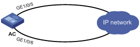
As shown in Figure 1, GigabitEthernet 1/0/5 on AC is the primary interface. GigabitEthernet 1/0/6 is its backup interface.
· When GigabitEthernet 1/0/5 is operating correctly, all traffic is transmitted through GigabitEthernet 1/0/5.
· When GigabitEthernet 1/0/5 fails, GigabitEthernet 1/0/6 takes over.
· When GigabitEthernet 1/0/5 is recovered, it preempts the active backup interface because it is the primary interface.
Figure 1 Strict active/backup mode
Load sharing mode
In load sharing mode, the backup interfaces are activated to transmit traffic depending on the traffic load on the primary interface.
· When the amount of traffic on the primary interface exceeds the upper threshold, the backup interfaces are activated in descending order of priority. This action continues until the traffic drops below the upper threshold.
· When the total amount of traffic on all load-shared interfaces decreases below the lower threshold, the backup interfaces are deactivated in ascending order of priority. This action continues until the total amount of traffic exceeds the lower threshold.
· When the primary interface fails (in DOWN state), the strict active/standby mode applies. Only one backup interface can forward traffic.
The upper and lower thresholds are user configurable.
|
|
NOTE: · "Traffic" on an interface refers to the amount of incoming or outgoing traffic, whichever is higher. · If two backup interfaces have the same priority, the one configured first has preference. |
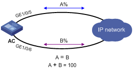
As shown in Figure 2, GigabitEthernet 1/0/5 on AC is the primary interface. GigabitEthernet 1/0/6 is its backup interface.
· When the amount of traffic on GigabitEthernet 1/0/5 exceeds the upper threshold, GigabitEthernet 1/0/6 is activated.
· When the total amount of traffic on all load-shared interfaces decreases below the lower threshold, GigabitEthernet 1/0/6 is deactivated.
Feature and hardware compatibility
|
Hardware series |
Model |
Interface backup compatibility |
|
WX1800H series |
WX1804H WX1810H WX1820H WX1840H |
Yes |
|
WX3800H series |
WX3820H WX3840H |
No |
|
WX5800H series |
WX5860H |
No |
Configuration restrictions and guidelines
When you configure interface backup, follow these restrictions and guidelines:
· An interface can be configured as a backup only for one interface.
· An interface cannot be both a primary and backup interface.
· For correct traffic forwarding, make sure the primary and backup interfaces have routes to the destination network.
Interface backup configuration task list
|
Task |
Remarks |
|
Configuring strict active/standby interface backup: · (Method 1.) Explicitly specifying backup interfaces without traffic thresholds · (Method 2.) Using interface backup with the Track module |
You cannot use these two methods at the same time for a primary interface and its backup interfaces. Use method 1 if you want to monitor the interface state of the primary interface for a switchover to occur. Use method 2 if you want to monitor any other state, such as the link state of the primary interface. |
|
A primary interface and its backup interfaces operate in load sharing mode after you specify the traffic thresholds on the primary interface. This method cannot be used with the other two methods at the same time for an interface. |
Configuring strict active/standby interface backup
You can use one of the following methods to configure strict active/standby interface backup:
· Explicitly specify backup interfaces for a primary interface. If this method is used, interface backup changes the state of the backup interface in response to the interface state change of the primary interface.
· Use interface backup with the Track module. If this method is used, interface backup uses a track entry to monitor the link state of the primary interface. Interface backup changes the state of a backup interface in response to the link state change of the primary interface.
Explicitly specifying backup interfaces without traffic thresholds
For the primary and backup interfaces to operate in strict active/standby mode, do not specify the traffic thresholds on the primary interface. If the traffic thresholds are configured, the interfaces will operate in load sharing mode.
You can assign priority to backup interfaces. When the primary interface fails, the backup interfaces are activated in descending order of priority, with the highest-priority interface activated first. If two backup interfaces have the same priority, the one configured first has preference.
To prevent link flapping from causing frequent interface switchovers, you can configure the following switchover delay timers:
· Up delay timer—Number of seconds that the primary or backup interface must wait before it can come up.
· Down delay timer—Number of seconds that the active primary or backup interface must wait before it is set to down state.
When the link of the active interface fails, the interface state does not change immediately. Instead, a down delay timer starts. If the link recovers before the timer expires, the interface state does not change. If the link is still down when the timer expires, the interface state changes to down.
To configure strict active/standby interface backup for a primary interface:
|
Step |
Command |
Remarks |
|
1. Enter system view. |
system-view |
N/A |
|
2. Enter interface view. |
interface interface-type interface-number |
This interface must be the primary interface. |
|
3. Specify a backup interface. |
backup interface interface-type interface-number [ priority ] |
By default, an interface does not have any backup interfaces. Repeat this command to specify up to three backup interfaces for the interface. |
|
4. Set the switchover delay timers. |
backup timer delay up-delay down-delay |
By default, the up and down delay timers are both 5 seconds. |
Using interface backup with the Track module
To use interface backup with the Track module to provide strict active/standby backup for a primary interface:
· Configure a track entry to monitor state information of the primary interface. For example, monitor its link state.
· Associate the track entry with a backup interface.
Interface backup changes the state of the backup interface in response to the track entry state, as shown in Table 2.
Table 2 Action on the backup interface in response to the track entry state change
|
Track entry state |
State of the monitored primary link |
Action on the backup interface |
|
Positive |
The primary link is operating correctly. |
Places the backup interface in STANDBY state. |
|
Negative |
The primary link has failed. |
Activates the backup interface to take over. |
|
NotReady |
The primary link is not monitored. This situation occurs when the track module or the monitoring module is not ready, for example, because the Track module is restarting or the monitoring settings are incomplete. In this situation, interface backup cannot obtain information about the primary link from the track module. |
· If the track entry state stays in NotReady state after it is created, interface backup does not change the state of the backup interface. · If the track entry state changes to NotReady from Positive or Negative, the backup interface changes back to the forwarding state before it was used for interface backup. |
For more information about configuring a track entry, see "Configuring Track."
When you associate a backup interface with a track entry, follow these guidelines:
· You can associate an interface with only one track entry.
· You can create the associated track entry before or after the association. The association takes effect after the track entry is created.
To associate Track with an interface:
|
Step |
Command |
Remarks |
|
1. Enter system view. |
system-view |
N/A |
|
2. Enter interface view. |
interface interface-type interface-number |
This interface must be the interface you are using as a backup. |
|
3. Associate the interface with a track entry. |
backup track track-entry-number |
By default, an interface is not associated with a track entry. |
Configuring load-shared interface backup
To implement load-balanced interface backup, you must configure the traffic thresholds on the primary interface. Interface backup regularly compares the amount of traffic with the thresholds to determine whether to activate or deactivate a backup interface. The traffic polling interval is user configurable.
You can assign priority to backup interfaces.
· When the amount of traffic on the primary interface exceeds the upper threshold, the backup interfaces are activated in descending order of priority.
· When the total amount of traffic on all load-shared interfaces decreases below the lower threshold, the backup interfaces are deactivated in ascending order of priority.
If two backup interfaces have the same priority, the one configured first has preference.
If a traffic flow has a fast forwarding entry, all packets of the flow will be forwarded out of the outgoing interface in the entry. The packets of the flow will not be distributed between interfaces when the upper threshold is reached. For more information about fast forwarding, see Layer 3—IP Services Configuration Guide.
To configure load-shared backup for an interface:
|
Step |
Command |
Remarks |
|
1. Enter system view. |
system-view |
N/A |
|
2. Enter interface view. |
interface interface-type interface-number |
You must enter the view of the primary interface. |
|
3. Configure a backup interface for the interface. |
backup interface interface-type interface-number [ priority ] |
By default, an interface does not have any backup interfaces. Repeat this command to specify up to three backup interfaces. |
|
4. Set backup load sharing thresholds. |
backup threshold upper-threshold lower-threshold |
By default, no traffic thresholds are configured. |
|
5. Set the traffic polling interval. |
backup timer flow-check interval |
The default interval is 30 seconds. |
Displaying and maintaining interface backup
Execute display commands in any view.
|
Command |
|
|
Display traffic statistics for load-shared interfaces. |
display interface-backup statistics |
|
Display the status of primary and backup interfaces. |
display interface-backup state |
Interface backup configuration examples
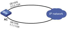
Strict active/standby interface backup configuration example
Network requirements
As shown in Figure 3:
· Specify GigabitEthernet 1/0/6 on AC to back up GigabitEthernet 1/0/5.
· Set the up and down delay timers to 10 seconds for the backup interfaces.

Configuration procedure
1. Assign IP addresses to interfaces, as shown in Figure 3. (Details not shown.)
2. On AC, configure backup interfaces and switchover delays:
# Specify GigabitEthernet 1/0/6 to back up GigabitEthernet 1/0/5.
[AC] interface gigabitethernet 1/0/5
[AC-GigabitEthernet1/0/5] backup interface gigabitethernet 1/0/6
# Set both up and down delay timers to 10 seconds.
[AC-GigabitEthernet1/0/5] backup timer delay 10 10
Verifying the configuration
# Display states of the primary and backup interfaces.
[AC-GigabitEthernet1/0/5] display interface-backup state
Interface: GE1/0/5
UpDelay: 10 s
DownDelay: 10 s
State: UP
Backup interfaces:
GE1/0/6 Priority: 0 State: STANDBY
The output shows that GigabitEthernet 1/0/5 is in UP state and the backup interface is in STANDBY state.
# Shut down the primary interface GigabitEthernet 1/0/5.
[AC-GigabitEthernet1/0/5] shutdown
[AC-GigabitEthernet1/0/5] display interface-backup state
Interface: GE1/0/5
UpDelay: 10 s
DownDelay: 10 s
State: DOWN
Backup interfaces:
GE1/0/6 Priority: 0 State: UP
Strict active/standby interface backup with the Track module configuration example
Network requirements
As shown in Figure 4, configure a track entry to monitor the link state of GigabitEthernet 1/0/5. When the link of GigabitEthernet 1/0/5 fails, the backup interface GigabitEthernet 1/0/6 comes up to take over.
Configuration procedure
1. Assign IP addresses to interfaces, as shown in Figure 4. (Details not shown.)
2. On AC, configure track settings:
# Configure track entry 1 to monitor the link state of GigabitEthernet 1/0/5.
[AC] track 1 interface gigabitethernet 1/0/5
# Associate track entry 1 with the backup interface GigabitEthernet 1/0/6.
[AC] interface gigabitethernet 1/0/6
[AC-GigabitEthernet1/0/6] backup track 1
[AC-GigabitEthernet1/0/6] quit
Verifying the configuration
# Verify that the backup interface GigabitEthernet 1/0/6 is in STANDBY state while the primary link is operating correctly.
[AC] display interface-backup state
IB Track Information:
GE1/0/6 Track: 1 State: STANDBY
# Shut down the primary interface GigabitEthernet 1/0/5.
[AC] interface gigabitethernet 1/0/5
[AC-GigabitEthernet1/0/5] shutdown
# Verify that the backup interface GigabitEthernet 1/0/6 comes up after the primary link goes down.
[AC-GigabitEthernet1/0/5] display interface-backup state
IB Track Information:
GE1/0/6 Track: 1 State: UP
Load-shared interface backup configuration example
Network requirements
As shown in Figure 5:
· Configure GigabitEthernet 1/0/6 on AC to back up the primary interface GigabitEthernet 1/0/5.
· On the primary interface:
? Specify the interface bandwidth used for traffic load calculation.
? Set the upper and lower thresholds to 80 and 20, respectively.
Configuration procedure
1. Assign IP addresses to interfaces, as shown in Figure 5. (Details not shown.)
2. On AC, configure backup interfaces and traffic thresholds:
# Specify GigabitEthernet 1/0/6 to back up GigabitEthernet 1/0/5.
[AC] interface gigabitethernet 1/0/5
[AC-GigabitEthernet1/0/5] backup interface gigabitethernet 1/0/6
# Set the expected bandwidth to 10000 kbps on the primary interface.
[AC-GigabitEthernet1/0/5] bandwidth 10000
# Set the upper and lower thresholds to 80 and 20, respectively.
[AC-GigabitEthernet1/0/5] backup threshold 80 20
Verifying the configuration
# Display traffic statistics for load-shared interfaces.
[AC-GigabitEthernet1/0/5] display interface-backup statistics
Interface: GigabitEthernet1/0/5
Statistics interval: 30 s
Bandwidth: 10000000 bps
PrimaryTotalIn: 102 bytes
PrimaryTotalOut: 108 bytes
PrimaryIntervalIn: 102 bytes
PrimaryIntervalOut: 108 bytes
Primary used bandwidth: 28 bps
TotalIn: 102 bytes
TotalOut: 108 bytes
TotalIntervalIn: 102 bytes
TotalIntervalOut: 108 bytes
Total used bandwidth: 28 bps
The output shows that the upper traffic threshold has not been exceeded. All traffic is transmitted through the primary interface GigabitEthernet 1/0/5.
# Verify that the backup interface is in STANDBY state because the upper threshold has not been exceeded.
[AC-GigabitEthernet1/0/5] display interface-backup state
Interface: GE1/0/5
UpDelay: 5 s
DownDelay: 5 s
Upper threshold: 80
Lower threshold: 20
State: UP
Backup interfaces:
GE1/0/6 Priority: 0 State: STANDBY
# Increase the incoming or outgoing traffic rate to be higher than 8000 kbps (80% of the specified bandwidth) on the primary interface. (Details not shown.)
# Verify that the backup interface GigabitEthernet 1/0/6 comes up to participate in traffic forwarding.
[AC-GigabitEthernet1/0/5] display interface-backup state
Interface: GE1/0/5
UpDelay: 5 s
Upper threshold: 80
Lower threshold: 20
State: UP
Backup interfaces:
GE1/0/6 Priority: 0 State: UP
Configuring Track
Overview
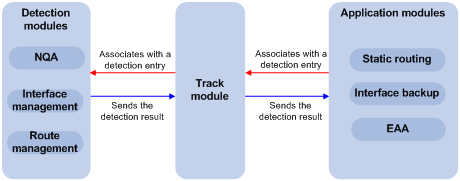
The Track module works between application modules and detection modules, as shown in Figure 6. It shields the differences between various detection modules from application modules.
Collaboration is enabled when you associate the Track module with a detection module and an application module, and it operates as follows:
1. The detection module probes specific objects such as interface status, link status, network reachability, and network performance, and informs the Track module of detection results.
2. The Track module sends the detection results to the application module.
3. When notified of changes for the tracked object, the application modules can react to avoid communication interruption and network performance degradation.
Figure 6 Collaboration through the Track module
Collaboration fundamentals
The Track module collaborates with detection modules and application modules.
Collaboration between the Track module and a detection module
The detection module sends the detection result of the tracked object to the Track module. The Track module changes the status of the track entry as follows:
· If the tracked object operates correctly, the state of the track entry is Positive. For example, the track entry state is Positive in one of the following conditions:
? The target interface is up.
? The target network is reachable.
· If the tracked object does not operate correctly, the state of the track entry is Negative. For example, the track entry state is Negative in one of the following conditions:
? The target interface is down.
? The target network is unreachable.
· If the detection result is invalid, the state of the track entry is NotReady. For example, the track entry state is NotReady if its associated NQA operation does not exist.
The following detection modules can be associated with the Track module:
· NQA.
· Interface management.
· Route management.
You can associate a track entry with an object of a detection module, such as the state of an interface or reachability of an IP route. The state of the track entry is determined by the state of the tracked object.
You can also associate a track entry with a list of objects called a tracked list. The state of a tracked list is determined by the states of all objects in the list. The following types of tracked lists are supported:
· Boolean AND list—The state of a Boolean AND list is determined by the states of the tracked objects using the Boolean AND operation.
· Boolean OR list—The state of a Boolean OR list is determined by the states of the tracked objects using the Boolean OR operation.
· Percentage threshold list—The state of a percentage threshold list is determined by comparing the percentage of positive and negative objects in the list with the percentage thresholds configured for the list.
· Weight threshold list—The state of a weight threshold list is determined by comparing the weight of positive and negative objects in the list with the weight thresholds configured for the list.
Collaboration between the Track module and an application module
The following application modules can be associated with the Track module:
· Static routing.
· EAA.
When configuring a track entry for an application module, you can set a notification delay to avoid immediate notification of status changes.
When the delay is not configured and the route convergence is slower than the link state change notification, communication failures occur.
Track configuration task list
To implement the collaboration function, establish associations between the Track module and detection modules, and between the Track module and application modules.
To configure the Track module, perform the following tasks:
|
Tasks at a glance |
|
|
Associating the Track module with a detection module object |
Perform a minimum of one task. |
|
Associating Track with a tracked list: · Associating Track with a Boolean list |
|
|
(Required.) Associating the Track module with an application module: · Associating Track with static routing |
Perform a minimum of one task. |
Associating the Track module with a detection module object
Associating Track with NQA
NQA supports multiple operation types to analyze network performance and service quality. For example, an NQA operation can periodically detect whether a destination is reachable, or whether a TCP connection can be established.
An NQA operation operates as follows when it is associated with a track entry:
· If the consecutive failures reach the specified threshold, the NQA module notifies the Track module that the tracked object has malfunctioned. The Track module then sets the track entry to Negative state.
· If the specified threshold is not reached, the NQA module notifies the Track module that the tracked object is operating correctly. The Track module then sets the track entry to Positive state.
For more information about NQA, see Network Management and Monitoring Configuration Guide.
To associate Track with NQA:
|
Step |
Command |
Remarks |
|
1. Enter system view. |
system-view |
N/A |
|
2. Create a track entry, associate it with an NQA reaction entry, and enter track entry view. |
track track-entry-number nqa entry admin-name operation-tag reaction item-number |
By default, no track entries exist. If the specified NQA operation or the reaction entry in the track entry does not exist, the status of the track entry is NotReady. |
|
3. Set the delay for notifying the application module of track entry state changes. |
delay { negative negative-time | positive positive-time } * |
By default, the Track module notifies the application module immediately when the track entry state changes. |
Associating Track with interface management
The interface management module monitors the link status or network-layer protocol status of interfaces. The associated Track and interface management operate as follows:
· When the link or network-layer protocol status of the interface changes to up, the interface management module informs the Track module of the change. The Track module sets the track entry to Positive state.
· When the link or network-layer protocol status of the interface changes to down, the interface management module informs the Track module of the change. The Track module sets the track entry to Negative state.
To associate Track with interface management:
|
Step |
Command |
Remarks |
|
1. Enter system view. |
system-view |
N/A |
|
2. Create a track entry, associate it with an interface, and enter track entry view. |
· Create a track entry to monitor the link
status of an interface: · Create a track entry to monitor the physical status
of an interface: · Create a track entry to monitor the network-layer protocol status of an
interface: |
By default, no track entries exist. |
|
3. Set the delay for notifying the application module of track entry state changes. |
delay { negative negative-time | positive positive-time } * |
By default, the Track module notifies the application module immediately when the track entry state changes. |
Associating Track with route management
The route management module monitors changes of route entries in the routing table. The associated Track and route management operate as follows:
· When a monitored route entry is found in the routing table, the route management module informs the Track module. The Track module sets the track entry to Positive state.
· When a monitored route entry is removed from the routing table, the route management module informs the Track module of the change. The Track module sets the track entry to Negative state.
To associate Track with route management:
|
Step |
Command |
Remarks |
|
1. Enter system view. |
system-view |
N/A |
|
2. Create a track entry to monitor the reachability of an IP route and enter track entry view. |
track track-entry-number ip route ip-address { mask-length | mask } reachability |
By default, no track entries exist. |
|
3. Set the delay for notifying the application module of track entry state changes. |
delay { negative negative-time | positive positive-time } * |
By default, the Track module notifies the application module immediately when the track entry state changes. |
Associating Track with a tracked list
Associating Track with a Boolean list
About Boolean list
A Boolean list is a list of tracked objects based on a Boolean logic. It can be further divided into the following types:
· Boolean AND list—A Boolean AND list is set to the positive state only when all objects are in positive state. If one or more objects are in negative state, the list is set to the negative state.
· Boolean OR list—A Boolean or list is set to the positive state if any object is in positive state. If all objects are in negative state, the list is set to the negative state.
Procedure
To associate Track with a Boolean list:
|
Step |
Command |
Remark |
|
4. Enter system view. |
system-view |
N/A |
|
5. Create a track entry. |
See "Associating the Track module with a detection module object." |
Create a track entry before you add it as a tracked object to a tracked list. A minimum of one track entry must be created. |
|
6. Create a Boolean tracked list and enter its view. |
track track-entry-number list boolean { and | or } |
By default, no tracked lists exist. |
|
7. Add the track entry as an object to the tracked list. |
object track-entry-number [ not ] |
By default, a tracked list does not contain any objects. Repeat this step to add all interested objects to the tracked list. |
|
8. (Optional.) Set the delay for notifying the application module of tracked list state changes. |
delay { negative negative-time | positive positive-time } * |
By default, the Track module notifies the application module immediately when the tracked list state changes. |
Associating Track with a percentage threshold list
About percentage threshold list
A percentage threshold list uses a percentage threshold to determine the state of the list.
· If the percentage of negative objects is equal to or smaller than the negative state threshold, the list is set to the negative state.
· If the percentage of positive objects is equal to or greater than the positive state threshold, the list is set to the positive state.
· The state of the list remains unchanged in the following conditions:
? The percentage of positive objects is smaller than the positive state threshold value.
? The percentage of negative objects is greater than the negative state threshold value.
Procedure
To associate Track with a percentage threshold list:
|
Task |
Command |
Remark |
|
9. Enter system view. |
system-view |
N/A |
|
10. Create a track entry. |
See "Associating the Track module with a detection module object." |
Create a track entry before you add it as an tracked object to a tracked list. A minimum of one track entry must be created. |
|
11. Create a percentage threshold list and enter its view. |
track track-entry-number list threshold percentage |
By default, no tracked lists exist. |
|
12. Add the track entry as an object to the tracked list. |
object track-entry-number [ not ] |
By default, a tracked list does not contain any objects. Repeat this step to add all interested objects to the tracked list. |
|
13. Configure the threshold values used to determine the state of the percentage threshold list. |
threshold percentage { negative negative-threshold | positive positive-threshold } * |
By default, the negative state threshold is 0% and the positive state threshold is 1%. |
|
14. (Optional.) Set the delay for notifying the application module of tracked list state changes. |
delay { negative negative-time | positive positive-time } * |
By default, the Track module notifies the application module immediately when the tracked list state changes. |
Associating Track with a weight threshold list
About weight threshold list
A weight threshold list uses a weight threshold to determine the state of the list.
· If the total weight of positive objects is equal to or greater than the positive state threshold, the list is set to the positive state.
· If the total weight of negative objects is equal to or smaller than the negative state threshold, the list is set to the negative state.
· The state the list remains unchanged in the following conditions:
? The total weight of positive objects is smaller than the positive state threshold value.
? The total weight of negative objects is greater than the negative state threshold value.
Procedure
To associate Track with a weight threshold list:
|
Task |
Command |
Remark |
|
15. Enter system view. |
system-view |
N/A |
|
16. Create a track entry. |
See "Associating the Track module with a detection module object." |
Create a track entry before you add it as an tracked object to a tracked list. A minimum of one track entry must be created. |
|
17. Create a weight threshold list and enter its view. |
track track-entry-number list threshold weight |
By default, no tracked lists exist. |
|
18. Add the track entry as an object to the tracked list. |
object track-entry-number [ not ] |
By default, a tracked list does not contain any objects. Repeat this step to add all interested objects to the tracked list. |
|
19. Configure the threshold values used to determine the state of the weight threshold list. |
threshold weight { negative negative-threshold | positive positive-threshold } * |
By default, the negative state threshold is 0 and the positive state threshold is 1. |
|
20. (Optional.) Set the delay for notifying the application module of tracked list state changes. |
delay { negative negative-time | positive positive-time } * |
By default, the Track module notifies the application module immediately when the tracked list state changes. |
Associating the Track module with an application module
Before you associate the Track module with an application module, make sure the associated track entry has been created.
Associating Track with static routing
A static route is a manually configured route to route packets. For more information about static route configuration, see Layer 3—IP Routing Configuration Guide.
Static routes cannot adapt to network topology changes. Link failures or network topological changes can make the routes unreachable and cause communication interruption.
To resolve this problem, configure another route to back up the static route. When the static route is reachable, packets are forwarded through the static route. When the static route is unreachable, packets are forwarded through the backup route.
To check the accessibility of a static route in real time, associate the Track module with the static route.
If you specify the next hop but not the output interface when configuring a static route, you can configure the static routing-Track-detection module collaboration. This collaboration enables you to verify the accessibility of the static route based on the track entry state.
· If the track entry is in Positive state, the following conditions exist:
? The next hop of the static route is reachable.
? The configured static route is valid.
· If the track entry is in Negative state, the following conditions exist:
? The next hop of the static route is not reachable.
? The configured static route is invalid.
· If the track entry is in NotReady state, the following conditions exist:
? The accessibility of the next hop of the static route is unknown.
? The static route is valid.
If a static route needs route recursion, the associated track entry must monitor the next hop of the recursive route. The next hop of the static route cannot be monitored. Otherwise, a valid route might be considered invalid.
To associate Track with static routing:
|
Step |
Command |
Remarks |
|
1. Enter system view. |
system-view |
N/A |
|
2. Associate a static route with a track entry to check the accessibility of the next hop. |
ip route-static { dest-address { mask-length | mask } | group group-name } { interface-type interface-number [ next-hop-address ] | next-hop-address } [ permanent | track track-entry-number ] [ preference preference-value ] [ tag tag-value ] [ description description-text ] |
By default, Track is not associated with static routing. |
Associating Track with interface backup
The following matrix shows the feature and hardware compatibility:
|
Hardware series |
Model |
Feature compatibility |
|
WX1800H series |
WX1804H WX1810H WX1820H WX1840H |
Yes |
|
WX3800H series |
WX3820H WX3840H |
No |
|
WX5800H series |
WX5860H |
No |
Interface backup allows interfaces on a device to back up each other, with the active interface transmitting data and the standby interfaces staying in backup state. When the active interface or the link where the active interface resides fails, a standby interface takes over to transmit data. This feature enhances the availability of the network. For more information, see "Configuring interface backup."
To enable a standby interface to detect the status of the active interface, you can associate the standby interface with a track entry.
· If the track entry is in Positive state, the following conditions exist:
? The link where the active interface resides operates correctly.
? The standby interfaces stay in backup state.
· If the track entry is in Negative state, the following conditions exist:
? The link where the active interface resides has failed.
? A standby interface changes to the active interface for data transmission.
· If the track entry is in always NotReady state, the following conditions exist:
? The association does not take effect.
? Each interface keeps its original forwarding state.
When the track entry turns to NotReady from other state, a standby interface becomes the active interface.
To associate Track with interface backup:
|
Step |
Command |
Remarks |
|
1. Enter system view. |
system-view |
N/A |
|
2. Enter interface view. |
interface interface-type interface-number |
N/A |
|
3. Associate the interface with a track entry. |
backup track track-entry-number |
By default, no track entry is associated with an interface. You can associate an interface with only one track entry. If you use this command multiple times, the most recent configuration takes effect. |
Associating Track with EAA
About Track association with EAA
You can configure EAA track event monitor policies to monitor the positive-to-negative or negative-to-positive state changes of track entries.
· If you specify only one track entry for a policy, EAA triggers the policy when it detects the specified state change on the track entry.
· If you specify multiple track entries for a policy, EAA triggers the policy when it detects the specified state change on the last monitored track entry. For example, if you configure a policy to monitor the positive-to-negative state change of multiple track entries, EAA triggers the policy when the last positive track entry monitored by the policy is changed to the Negative state.
You can set a suppression time for a track event monitor policy. The timer starts when the policy is triggered. The system does not process messages that report the monitored track event until the timer times out.
For more information about EAA, see Network Management and Monitoring Configuration Guide.
Procedure
To associate Track with EAA:
|
Step |
Command |
Remarks |
|
4. Enter system view. |
system-view |
N/A |
|
5. Create a CLI-defined monitor policy and enter its view, or enter the view of an existing CLI-defined monitor policy. |
rtm cli-policy policy-name |
By default, no CLI-defined monitor policies exist. |
|
6. Configure a track event. |
event track track-entry-number-list state { negative | positive } [ suppress-time suppress-time ] |
By default, a monitor policy does not contain any track event. |
Displaying and maintaining track entries
Execute display commands in any view.
|
Task |
Command |
|
Display information about track entries. |
display track { track-entry-number | all [ negative | positive ] } [ brief ] |
Static routing-Track-NQA collaboration configuration example
Network requirements
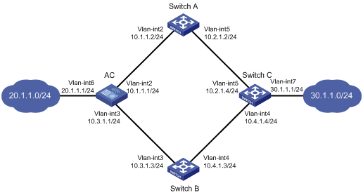
As shown in Figure 7:
· The AC is the default gateway of the hosts in network 20.1.1.0/24.
· Switch C is the default gateway of the hosts in network 30.1.1.0/24.
· Hosts in the two networks communicate with each other through static routes.
To ensure network availability, configure route backup and static routing-Track-NQA collaboration on the AC and Switch C as follows:
· On the AC, assign a higher priority to the static route to 30.1.1.0/24 with the next hop Switch A. This route is the master route. The static route to 30.1.1.0/24 with the next hop Switch B acts as the backup route. When the master route is unavailable, the backup route takes effect. The AC forwards packets to 30.1.1.0/24 through Switch B.
· On Switch C, assign a higher priority to the static route to 20.1.1.0/24 with the next hop Switch A. This route is the master route. The static route to 20.1.1.0/24 with the next hop Switch B acts as the backup route. When the master route is unavailable, the backup route takes effect. Switch C forwards packets to 20.1.1.0/24 through Switch B.
Configuration procedure
1. Create VLANs and assign ports to them. Configure the IP address of each VLAN interface, as shown in Figure 7. (Details not shown.)
2. Configure the AC:
# Configure a static route to 30.1.1.0/24 with the next hop 10.1.1.2 and the default priority 60. Associate this static route with track entry 1.
<AC> system-view
[AC] ip route-static 30.1.1.0 24 10.1.1.2 track 1
# Configure a static route to 30.1.1.0/24 with the next hop 10.3.1.3 and the priority 80.
[AC] ip route-static 30.1.1.0 24 10.3.1.3 preference 80
# Configure a static route to 10.2.1.4 with the next hop 10.1.1.2.
[AC] ip route-static 10.2.1.4 24 10.1.1.2
# Create an NQA operation with the administrator admin and the operation tag test.
[AC] nqa entry admin test
# Configure the operation type as ICMP echo.
[AC-nqa-admin-test] type icmp-echo
# Specify 10.2.1.4 as the destination address of the operation.
[AC-nqa-admin-test-icmp-echo] destination ip 10.2.1.4
# Specify 10.1.1.2 as the next hop of the operation.
[AC-nqa-admin-test-icmp-echo] next-hop ip 10.1.1.2
# Configure the ICMP echo operation to repeat every 100 milliseconds.
[AC-nqa-admin-test-icmp-echo] frequency 100
# Configure reaction entry 1, specifying that five consecutive probe failures trigger the Track module.
[AC-nqa-admin-test-icmp-echo] reaction 1 checked-element probe-fail threshold-type consecutive 5 action-type trigger-only
[AC-nqa-admin-test-icmp-echo] quit
# Start the NQA operation.
[AC] nqa schedule admin test start-time now lifetime forever
# Configure track entry 1, and associate it with reaction entry 1 of the NQA operation.
[AC] track 1 nqa entry admin test reaction 1
3. Configure Switch A:
# Configure a static route to 30.1.1.0/24 with the next hop 10.2.1.4.
<SwitchA> system-view
[SwitchA] ip route-static 30.1.1.0 24 10.2.1.4
# Configure a static route to 20.1.1.0/24 with the next hop 10.1.1.1.
[SwitchA] ip route-static 20.1.1.0 24 10.1.1.1
4. Configure Switch B:
# Configure a static route to 30.1.1.0/24 with the next hop 10.4.1.4.
<SwitchB> system-view
[SwitchB] ip route-static 30.1.1.0 24 10.4.1.4
# Configure a static route to 20.1.1.0/24 with the next hop 10.3.1.1.
[SwitchB] ip route-static 20.1.1.0 24 10.3.1.1
5. Configure Switch C:
# Configure a static route to 20.1.1.0/24 with the next hop 10.2.1.2 and the default priority 60. Associate this static route with track entry 1.
<SwitchC> system-view
[SwitchC] ip route-static 20.1.1.0 24 10.2.1.2 track 1
# Configure a static route to 20.1.1.0/24 with the next hop 10.4.1.3 and the priority 80.
[SwitchC] ip route-static 20.1.1.0 24 10.4.1.3 preference 80
# Configure a static route to 10.1.1.1 with the next hop 10.2.1.2.
[SwitchC] ip route-static 10.1.1.1 24 10.2.1.2
# Create an NQA operation with the administrator admin and the operation tag test.
[SwitchC] nqa entry admin test
# Specify the operation type as ICMP echo.
[SwitchC-nqa-admin-test] type icmp-echo
# Specify 10.1.1.1 as the destination address of the operation.
[SwitchC-nqa-admin-test-icmp-echo] destination ip 10.1.1.1
# Specify 10.2.1.2 as the next hop of the operation.
[SwitchC-nqa-admin-test-icmp-echo] next-hop ip 10.2.1.2
# Configure the ICMP echo operation to repeat every 100 milliseconds.
[SwitchC-nqa-admin-test-icmp-echo] frequency 100
# Configure reaction entry 1, specifying that five consecutive probe failures trigger the Track module.
[SwitchC-nqa-admin-test-icmp-echo] reaction 1 checked-element probe-fail threshold-type consecutive 5 action-type trigger-only
[SwitchC-nqa-admin-test-icmp-echo] quit
# Start the NQA operation.
[SwitchC] nqa schedule admin test start-time now lifetime forever
# Configure track entry 1, and associate it with reaction entry 1 of the NQA operation.
[SwitchC] track 1 nqa entry admin test reaction 1
Verifying the configuration
# Display information about the track entry on the AC.
[AC] display track all
Track ID: 1
State: Positive
Duration: 0 days 0 hours 0 minutes 32 seconds
Notification delay: Positive 0, Negative 0 (in seconds)
Tracked object:
NQA entry: admin test
Reaction: 1
Remote IP/URL:--
Local IP:--
Interface:--
The output shows that the status of the track entry is Positive, indicating that the NQA operation has succeeded and the master route is available.
# Display the routing table of the AC.
[AC] display ip routing-table
Destinations : 10 Routes : 10
Destination/Mask Proto Pre Cost NextHop Interface
10.1.1.0/24 Direct 0 0 10.1.1.1 Vlan2
10.1.1.1/32 Direct 0 0 127.0.0.1 InLoop0
10.2.1.0/24 Static 60 0 10.1.1.2 Vlan2
10.3.1.0/24 Direct 0 0 10.3.1.1 Vlan3
10.3.1.1/32 Direct 0 0 127.0.0.1 InLoop0
20.1.1.0/24 Direct 0 0 20.1.1.1 Vlan6
20.1.1.1/32 Direct 0 0 127.0.0.1 InLoop0
30.1.1.0/24 Static 60 0 10.1.1.2 Vlan2
127.0.0.0/8 Direct 0 0 127.0.0.1 InLoop0
127.0.0.1/32 Direct 0 0 127.0.0.1 InLoop0
The output shows that the AC forwards packets to 30.1.1.0/24 through Switch A.
# Remove the IP address of interface VLAN-interface 2 on Switch A.
<SwitchA> system-view
[SwitchA] interface vlan-interface 2
[SwitchA-Vlan-interface2] undo ip address
# Display information about the track entry on the AC.
[AC] display track all
Track ID: 1
State: Negative
Duration: 0 days 0 hours 0 minutes 32 seconds
Notification delay: Positive 0, Negative 0 (in seconds)
Tracked object:
NQA entry: admin test
Reaction: 1
Remote IP/URL:--
Local IP:--
Interface:--
The output shows that the status of the track entry is Negative, indicating that the NQA operation has failed and the master route is unavailable.
# Display the routing table of the AC.
[AC] display ip routing-table
Destinations : 10 Routes : 10
Destination/Mask Proto Pre Cost NextHop Interface
10.1.1.0/24 Direct 0 0 10.1.1.1 Vlan2
10.1.1.1/32 Direct 0 0 127.0.0.1 InLoop0
10.2.1.0/24 Static 60 0 10.1.1.2 Vlan2
10.3.1.0/24 Direct 0 0 10.3.1.1 Vlan3
10.3.1.1/32 Direct 0 0 127.0.0.1 InLoop0
20.1.1.0/24 Direct 0 0 20.1.1.1 Vlan6
20.1.1.1/32 Direct 0 0 127.0.0.1 InLoop0
30.1.1.0/24 Static 80 0 10.3.1.3 Vlan3
127.0.0.0/8 Direct 0 0 127.0.0.1 InLoop0
127.0.0.1/32 Direct 0 0 127.0.0.1 InLoop0
The output shows that the AC forwards packets to 30.1.1.0/24 through Switch B. The backup static route has taken effect.
# Verify that hosts in 20.1.1.0/24 can communicate with the hosts in 30.1.1.0/24 when the master route fails.
[AC] ping -a 20.1.1.1 30.1.1.1
Ping 30.1.1.1: 56 data bytes, press CTRL_C to break
Reply from 30.1.1.1: bytes=56 Sequence=1 ttl=254 time=2 ms
Reply from 30.1.1.1: bytes=56 Sequence=2 ttl=254 time=1 ms
Reply from 30.1.1.1: bytes=56 Sequence=3 ttl=254 time=1 ms
Reply from 30.1.1.1: bytes=56 Sequence=4 ttl=254 time=2 ms
Reply from 30.1.1.1: bytes=56 Sequence=5 ttl=254 time=1 ms
--- Ping statistics for 30.1.1.1 ---
5 packet(s) transmitted, 5 packet(s) received, 0.00% packet loss
round-trip min/avg/max/std-dev = 1/1/2/1 ms
# Verify that the hosts in 30.1.1.0/24 can communicate with the hosts in 20.1.1.0/24 when the master route fails.
[SwitchA] ping -a 30.1.1.1 20.1.1.1
Ping 20.1.1.1: 56 data bytes, press CTRL_C to break
Reply from 20.1.1.1: bytes=56 Sequence=1 ttl=254 time=2 ms
Reply from 20.1.1.1: bytes=56 Sequence=2 ttl=254 time=1 ms
Reply from 20.1.1.1: bytes=56 Sequence=3 ttl=254 time=1 ms
Reply from 20.1.1.1: bytes=56 Sequence=4 ttl=254 time=1 ms
Reply from 20.1.1.1: bytes=56 Sequence=5 ttl=254 time=1 ms
--- Ping statistics for 20.1.1.1 ---
5 packet(s) transmitted, 5 packet(s) received, 0.00% packet loss
round-trip min/avg/max/std-dev = 1/1/2/1 ms
Load balancing overview
Load balancing (LB) is a cluster technology that distributes services among multiple network devices or links.
Restrictions: Hardware compatibility with load balancing
|
Hardware series |
Model |
Load balancing compatibility |
|
WX1800H |
WX1804H WX1810H WX1820H WX1840H |
Yes |
|
WX3800H |
WX3820H WX3840H |
No |
|
WX5800H |
WX5860H |
No |
Advantages of load balancing
Load balancing has the following advantages:
· High performance—Improves overall system performance by distributing services to multiple devices or links.
· Scalability—Meets increasing service requirements without compromising service quality by easily adding devices or links.
· High availability—Improves overall availability by using backup devices or links.
· Manageability—Simplifies configuration and maintenance by centralizing management on the load balancing device.
· Transparency—Preserves the transparency of the network topology for end users. Adding or removing devices or links does not affect services.
Load balancing types
The device supports the link load balancing type. Link load balancing applies to a network environment where there are multiple carrier links to implement dynamic link selection. This enhances link utilization. Link load balancing supports IPv4 and IPv6, but does not support IPv4-to-IPv6 packet translation. Link load balancing is classified into the following types:
· Outbound link load balancing—Load balances traffic among the links from the internal network to the external network.
· Transparent DNS proxy—Load balances DNS requests among the links from the internal network to the external network.
Configuring outbound link load balancing
About outbound link load balancing
Outbound link load balancing load balances traffic among the links from the internal network to the external network.
Typical network diagram
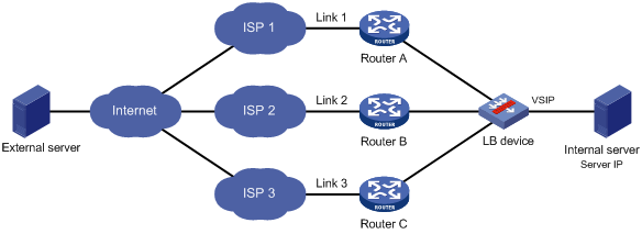
As shown in Figure 8, outbound link load balancing contains the following elements:
· LB device—Distributes outbound traffic among multiple links.
· Link—Physical links provided by ISPs.
· VSIP—Virtual service IP address of the cluster, which identifies the destination network for packets from the internal network.
· Server IP—IP address of a server.
Workflow
Figure 9 shows the outbound link load balancing workflow.
Figure 9 Outbound link load balancing workflow
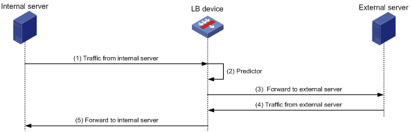
The workflow for outbound link load balancing is as follows:
1. The LB device receives traffic from the internal server.
2. The LB device selects the optimal link based on the LB policy, sticky method, proximity algorithm, and scheduling algorithm (typically the bandwidth algorithm or maximum bandwidth algorithm) in turn.
3. The LB device forwards the traffic to the external server through the optimal link.
4. The LB device receives traffic from the external server.
5. The LB device forwards the traffic to the internal server.
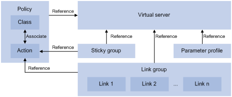
Outbound link load balancing configuration task list
Figure 10 shows the relationship between the following configuration items:
· Link group—A collection of links that contain similar functions. A link group can be referenced by a virtual server or an LB action.
· Link—Physical links provided by ISPs.
· Virtual server—A virtual service provided by the LB device to determine whether to perform load balancing for packets received on the LB device. Only the packets that match a virtual server are load balanced.
· LB class—Classifies packets to implement load balancing based on packet type.
· LB action—Drops, forwards, or modifies packets.
· LB policy—Associates an LB class with an LB action. An LB policy can be referenced by a virtual server.
· Sticky group—Uses a sticky method to distribute similar sessions to the same link. A sticky group can be referenced by a virtual server or an LB action.
· Parameter profile—Defines advanced parameters to process packets. A parameter profile can be referenced by a virtual server.
Figure 10 Relationship between the main configuration items
To configure outbound link load balancing, perform the following tasks:
|
Tasks at a glance |
|
(Required.) Configuring a link group |
|
(Required.) Configuring a link |
|
(Required.) Configuring a virtual server |
|
(Optional.) Configuring an LB class |
|
(Optional.) Configuring an LB class |
|
(Optional.) Configuring an LB policy |
|
(Optional.) Configuring a sticky group |
|
(Optional.) Configuring a parameter profile |
|
(Optional.) Configuring ISP information |
|
(Optional.) Configuring the ALG feature |
|
(Optional.) Performing a load balancing test |
|
(Optional.) Enabling SNMP notifications |
Configuring a link group
You can add links that contain similar functions to a link group to facilitate management.
Link group configuration task list
|
Tasks at a glance |
|
(Required.) Creating a link group |
|
(Required.) Scheduling links |
|
(Required.) Setting the availability criteria |
|
(Required.) Disabling NAT |
|
(Optional.) Configuring SNAT |
|
(Optional.) Enabling the slow online feature |
|
(Optional.) Configuring health monitoring |
|
(Optional.) Specifying a fault processing method |
|
(Optional.) Configuring the proximity feature |
Creating a link group
|
Step |
Command |
Remarks |
|
1. Enter system view. |
system-view |
N/A |
|
2. Create a link group and enter link group view. |
loadbalance link-group link-group-name |
By default, no link groups exist. |
|
3. (Optional.) Set a description for the link group. |
description text |
By default, no description is set for a link group. |
Scheduling links
About scheduling links
Perform this task to specify a scheduling algorithm for a link group and specify the number of links to participate in scheduling. The LB device calculates the links to process user requests based on the specified scheduling algorithm.
The device provides the following scheduling algorithms for a link group:
· Weighted least connection algorithm (least-connection)—Always assigns user requests to the link with the fewest number of weighted active connections (the number of active connections divided by weight).
· Random algorithm (random)—Randomly assigns user requests to links.
· Round robin algorithm (round-robin)—Assigns user requests to links based on the weights of links. A higher weight indicates more user requests will be assigned.
· Bandwidth algorithm (bandwidth)—Distributes user requests to links according to the weights and remaining bandwidth of links.
· Maximum bandwidth algorithm (max-bandwidth)—Distributes user requests always to an idle link that has the largest remaining bandwidth.
· Source IP address hash algorithm (hash address source)—Hashes the source IP address of user requests and distributes user requests to different links according to the hash values.
· Source IP address and port hash algorithm (hash address source-ip-port)—Hashes the source IP address and port number of user requests and distributes user requests to different links according to the hash values.
· Destination IP address hash algorithm (hash address destination)—Hashes the destination IP address of user requests and distributes user requests to different links according to the hash values.
Procedure
|
Step |
Command |
Remarks |
|
1. Enter system view. |
system-view |
N/A |
|
2. Enter link group view. |
loadbalance link-group link-group-name |
N/A |
|
3. Specify a scheduling algorithm for the link group. |
predictor hash address { destination | source | source-ip-port } [ mask mask-length ] [ prefix prefix-length ] |
By default, the scheduling algorithm for a link group is weighted round robin. |
|
4. Specify the number of links to participate in scheduling. |
selected-link min min-number max max-number |
By default, the links with the highest priority participate in scheduling. |
Setting the availability criteria
About setting the availability criteria
Perform this task to set the criteria (lower percentage and higher percentage) to determine whether a link group is available. This helps implement traffic switchover between the master and backup link groups.
· When the number of available links to the total number of links in the master link group is smaller than the lower percentage, traffic is switched to the backup link group.
· When the number of available links to the total number of links in the master link group is greater than the upper percentage, traffic is switched back to the master link group.
Procedure
|
Step |
Command |
Remarks |
|
1. Enter system view. |
system-view |
N/A |
|
2. Enter link group view. |
loadbalance link-group link-group-name |
N/A |
|
3. Set the criteria to determine whether the link group is available. |
activate lower lower-percentage upper upper-percentage |
By default, when a minimum of one link is available, the link group is available. |
Disabling NAT
Restrictions and guidelines
Typically, outbound link load balancing networking requires disabling NAT for a link group.
Procedure
|
Step |
Command |
Remarks |
|
1. Enter system view. |
system-view |
N/A |
|
2. Enter link group view. |
loadbalance link-group link-group-name |
N/A |
|
3. Disable NAT for the link group. |
transparent enable |
By default, NAT is enabled for a link group. |
Configuring SNAT
About SNAT
After a link group references the SNAT address pool, the LB device replaces the source address of the packets it receives with an SNAT address before forwarding the packets.
Restrictions and guidelines
An SNAT address pool can have a maximum of 256 IPv4 addresses and 65536 IPv6 addresses. No overlapping IPv4 or IPv6 addresses are allowed in different SNAT address pools.
As a best practice, do not use SNAT because its application scope is limited for outbound link load balancing.
Procedure
|
Step |
Command |
Remarks |
|
1. Enter system view. |
system-view |
N/A |
|
2. Create an SNAT address pool and enter SNAT address pool view. |
loadbalance snat-pool pool-name |
By default, no SNAT address pools exist. |
|
3. (Optional.) Set a description for the SNAT address pool. |
description text |
By default, no description is set for an SNAT address pool. |
|
4. Specify an address range for the SNAT address pool. |
· Specify an IPv4 address range: · Specify an IPv6 address range: |
By default, no address range is specified for an SNAT address pool. |
|
5. Return to system view. |
quit |
N/A |
|
6. Enter link group view. |
loadbalance link-group link-group-name |
N/A |
|
7. Specify the SNAT address pool to be referenced by the link group. |
snat-pool pool-name |
By default, no SNAT address pool is referenced by a link group. |
Enabling the slow online feature
About the slow online feature
Links newly added to a link group might be unable to immediately process large numbers of services assigned by the LB device. To resolve this issue, enable the slow online feature for the link group. The feature uses the standby timer and ramp-up timer. When the links are brought online, the LB device does not assign any services to the links until the standby timer expires.
When the standby timer expires, the ramp-up timer starts. During the ramp-up time, the LB device increases the service amount according to the processing capability of the links, until the ramp-up timer expires.
Procedure
|
Step |
Command |
Remarks |
|
|
1. Enter system view. |
system-view |
N/A |
|
|
2. Enter link group view. |
loadbalance link-group link-group-name |
N/A |
|
|
3. Enable the slow online feature for the link group. |
slow-online [ standby-time standby-time ramp-up-time ramp-up-time ] |
By default, the slow online feature is disabled for a link group. |
|
Configuring health monitoring
About configuring health monitoring
Perform this task to enable health monitoring to detect the availability of links.
Restrictions and guidelines
The health monitoring configuration in link view takes precedence over the configuration in link group view.
Procedure
|
Step |
Command |
Remarks |
|
1. Enter system view. |
system-view |
N/A |
|
2. Enter link group view. |
loadbalance link-group link-group-name |
N/A |
|
3. Specify a health monitoring method for the link group. |
probe template-name |
By default, no health monitoring method is specified for a link group. |
|
4. Specify the health monitoring success criteria for the link group. |
success-criteria { all | at-least min-number } |
By default, health monitoring succeeds only when all the specified health monitoring methods succeed. |
Specifying a fault processing method
About fault processing methods
Perform this task to specify one of the following fault processing methods for a link group:
· Keep—Does not actively terminate the connection with the failed link. Keeping or terminating the connection depends on the timeout mechanism of the protocol.
· Reschedule—Redirects the connection to another available link in the link group.
· Reset—Terminates the connection with the failed link by sending RST packets (for TCP packets) or ICMP unreachable packets (for other types of packets).
Procedure
|
Step |
Command |
Remarks |
|
1. Enter system view. |
system-view |
N/A |
|
2. Enter link group view. |
loadbalance link-group link-group-name |
N/A |
|
3. Specify a fault processing method for the link group. |
fail-action { keep | reschedule | reset } |
By default, the fault processing method is keep. All available connections are kept. |
Configuring the proximity feature
About the proximity feature
The proximity feature performs link detection to select the optimal link to a destination. If no proximity information for a destination is available, the load balancing module selects a link based on the scheduling algorithm. It then performs proximity detection to generate proximity entries for forwarding subsequent traffic.
You can specify an NQA template or load-balancing probe template to perform link detection. The device generates proximity entries according to the detection results and proximity parameter settings. For information about NQA templates, see NQA configuration in Network Management and Monitoring Configuration Guide.
Restrictions and guidelines
To configure the proximity feature, first configure proximity parameters in proximity view, and then enable the proximity feature in link group view.
Configuring proximity parameters
|
Step |
Command |
Remarks |
|
|
1. Enter system view. |
system-view |
N/A |
|
|
2. Enter proximity view. |
N/A |
||
|
3. Specify the proximity probe method for packets. |
match [ match-id ] tcp probe nqa-template |
By default, no proximity probe method is specified. |
|
|
4. Specify the default proximity probe method. |
match default probe nqa-template |
By default, the default proximity probe method is not specified. |
|
|
5. Set the mask length for IPv4 proximity entries. |
By default, the mask length for IPv4 proximity entries is 24. |
||
|
6. Set the prefix length for IPv6 proximity entries. |
By default, the prefix length for IPv6 proximity entries is 96. |
||
|
7. Set the network delay weight for proximity calculation. |
By default, the network delay weight for proximity calculation is 100. |
||
|
8. Set the TTL weight for proximity calculation. |
By default, the TTL weight for proximity calculation is 100. |
||
|
9. Set the bandwidth weight for proximity calculation. |
By default, the inbound or outbound bandwidth weight for proximity calculation is 100. |
||
|
10. Set the cost weight for proximity calculation. |
By default, the cost weight for proximity calculation is 100. |
||
|
11. Set the aging timer for proximity entries. |
By default, the aging timer for proximity entries is 60 seconds. |
||
|
12. Set the maximum number of proximity entries. |
By default, the maximum number of proximity entries is not set. |
||
Enabling the proximity feature
|
Step |
Command |
Remarks |
|
|
1. Enter system view. |
system-view |
N/A |
|
|
2. Enter link group view. |
N/A |
||
|
3. Enable the proximity feature. |
By default, the proximity feature is disabled for a link group. |
||
Configuring a link
A link is a physical link provided by an ISP. A link can belong to only one link group. A link group can have multiple links.
Link configuration task list
|
Tasks at a glance |
|
(Required.) Creating a link and specifying a link group |
|
(Required.) Specifying an outbound next hop for a link |
|
(Required.) Setting a weight and priority |
|
(Optional.) Configuring the bandwidth and connection parameters |
|
(Optional.) Configuring health monitoring |
|
(Optional.) Enabling the slow offline feature |
|
(Optional.) Setting the link cost for proximity calculation |
|
(Optional.) Setting the bandwidth ratio and maximum expected bandwidth |
Creating a link and specifying a link group
|
Step |
Command |
Remarks |
|
1. Enter system view. |
system-view |
N/A |
|
2. Create a link and enter link view. |
loadbalance link link-name |
By default, no links exist. |
|
3. (Optional.) Set a description for the link. |
description text |
By default, no description is set for a link. |
|
4. Specify a link group for the link. |
link-group link-group-name |
By default, a link does not belong to any link group. |
Specifying an outbound next hop for a link
|
Step |
Command |
Remarks |
|
1. Enter system view. |
system-view |
N/A |
|
2. Enter link view. |
loadbalance link link-name |
N/A |
|
3. Specify an outbound next hop for the link. |
· Specify the IPv4 address of the
outbound next hop: · Specify the IPv6 address of the
outbound next hop: |
By default, no outbound next hop is specified for a link. |
Setting a weight and priority
About setting a weight and priority
Perform this task to configure a weight for the weighted round robin and weighted least connection algorithms of a link, and the scheduling priority in the link group for the server.
Procedure
|
Step |
Command |
Remarks |
|
1. Enter system view. |
system-view |
N/A |
|
2. Enter link view. |
loadbalance link link-name |
N/A |
|
3. Set a weight for the link. |
weight weight-value |
By default, the weight of a link is 100. |
|
4. Set a priority for the link. |
priority priority |
By default, the priority of a link is 4. |
Configuring the bandwidth and connection parameters
|
Step |
Command |
Remarks |
|
1. Enter system view. |
system-view |
N/A |
|
2. Enter link view. |
loadbalance link link-name |
N/A |
|
3. Set the maximum bandwidth for the link. |
rate-limit bandwidth [ inbound | outbound ] bandwidth-value |
By default, the maximum bandwidth, inbound bandwidth, and outbound bandwidth are 0 KBps for a link. The bandwidths are not limited. |
|
4. Set the maximum number of connections for the link. |
connection-limit max max-number |
By default, the maximum number of connections is 0 for a link. The number is not limited. |
|
5. Set the maximum number of connections per second for the link. |
rate-limit connection connection-number |
By default, the maximum number of connections per second is 0 for a link. The number is not limited. |
Configuring health monitoring
About configuring health monitoring
Perform this task to enable health monitoring to detect the availability of a link.
Restrictions and guidelines
The health monitoring configuration in link view takes precedence over the configuration in link group view.
Procedure
|
Step |
Command |
Remarks |
|
1. Enter system view. |
system-view |
N/A |
|
2. Enter link view. |
loadbalance link link-name |
N/A |
|
3. Specify a health monitoring method for the link. |
probe template-name |
By default, no health monitoring method is specified for a link. |
|
4. Specify the health monitoring success criteria for the link. |
success-criteria { all | at-least min-number } |
By default, the health monitoring succeeds only when all the specified health monitoring methods succeed. |
Enabling the slow offline feature
About the slow offline feature
The shutdown command immediately terminates existing connections of a link. The slow offline feature ages out the connections, and does not establish new connections.
Restrictions and guidelines
To enable the slow offline feature for a link, you must execute the slow-shutdown enable command and then the shutdown command. If you execute the shutdown command and then the slow-shutdown enable command, the slow offline feature does not take effect and the link is shut down.
Procedure
|
Step |
Command |
Remarks |
|
1. Enter system view. |
system-view |
N/A |
|
2. Enter link view. |
loadbalance link link-name |
N/A |
|
3. Enable the slow offline feature for the link. |
slow-shutdown enable |
By default, the slow offline feature is disabled. |
|
4. Shut down the link. |
shutdown |
By default, the link is activated. |
Setting the link cost for proximity calculation
|
Step |
Command |
Remarks |
|
1. Enter system view. |
system-view |
N/A |
|
2. Enter link view. |
loadbalance link link-name |
N/A |
|
3. Set the link cost for proximity calculation. |
cost cost-value |
By default, the link cost for proximity calculation is 0. |
Setting the bandwidth ratio and maximum expected bandwidth
About setting the bandwidth ratio and maximum expected bandwidth
When the traffic exceeds the maximum expected bandwidth multiplied by the bandwidth ratio of a link, new traffic (traffic that does not match any sticky entries) is not distributed to the link. When the traffic drops below the maximum expected bandwidth multiplied by the bandwidth recovery ratio of the link, the link participates in scheduling again.
In addition to being used for link protection, the maximum expected bandwidth is used for remaining bandwidth calculation in the bandwidth algorithm, maximum bandwidth algorithm, and dynamic proximity algorithm.
Procedure
|
Step |
Command |
Remarks |
|
1. Enter system view. |
system-view |
N/A |
|
2. Enter link view. |
loadbalance link link-name |
N/A |
|
3. Set the bandwidth ratio. |
bandwidth [ inbound | outbound ] busy-rate busy-rate-number [ recovery recovery-rate-number ] |
By default, the total bandwidth ratio is 70. |
|
4. Set the maximum expected bandwidth. |
By default, the maximum expected bandwidth, maximum uplink expected bandwidth, and maximum downlink expected bandwidth are 0 KBps. The bandwidths are not limited. |
Configuring a virtual server
A virtual server is a virtual service provided by the LB device to determine whether to perform load balancing for packets received on the LB device. Only the packets that match a virtual server are load balanced.
Outbound link load balancing supports only the link-IP virtual server.
Virtual server configuration task list
|
Tasks at a glance |
Remarks |
|
(Required.) Creating a virtual server |
N/A |
|
(Required.) Specifying the VSIP and port number |
N/A |
|
(Required.) Specifying link groups |
Choose a minimum of one of the tasks. If both tasks are configured, packets are processed by the LB policy first. If the processing fails, the packets are processed by the specified link groups. |
|
(Required.) Specifying an LB policy |
|
|
(Optional.) Specifying a parameter profile |
N/A |
|
(Optional.) Configuring the bandwidth and connection parameters |
N/A |
|
(Optional.) Enabling the link protection feature |
N/A |
|
(Optional.) Enabling bandwidth statistics collection by interfaces |
N/A |
|
(Required.) Enabling a virtual server |
N/A |
Creating a virtual server
|
Step |
Command |
Remarks |
|
1. Enter system view. |
system-view |
N/A |
|
2. Create a link-IP virtual server and enter virtual server view. |
virtual-server virtual-server-name type link-ip |
By default, no virtual servers exist. |
|
3. (Optional.) Set a description for the virtual server. |
description text |
By default, no description is set for the virtual server. |
Specifying the VSIP and port number
|
Step |
Command |
Remarks |
|
1. Enter system view. |
system-view |
N/A |
|
2. Enter link-IP virtual server view. |
virtual-server virtual-server-name |
N/A |
|
3. Specify the VSIP for the virtual server. |
· Specify an IPv4 address: · Specify an IPv6 address: |
By default, no IPv4 or IPv6 address is specified for a virtual server. |
|
4. Specify the port number for the virtual server. |
port port-number |
By default, the port number is 0 (any ports) for a link-IP virtual server. |
Specifying link groups
About specifying link groups
When the primary link group is available (contains available links), the virtual server forwards packets through the primary link group. When the primary link group is not available, the virtual server forwards packets through the backup link group.
Procedure
|
Step |
Command |
Remarks |
|
1. Enter system view. |
system-view |
N/A |
|
2. Enter virtual server view. |
virtual-server virtual-server-name |
N/A |
|
3. Specify link groups. |
default link-group link-group-name [ backup backup-link-group-name ] [ sticky sticky-name ] |
By default, no link group is specified for a virtual server. |
Specifying an LB policy
About specifying an LB policy
By referencing an LB policy, the virtual server load balances matching packets based on the packet contents.
Procedure
|
Step |
Command |
Remarks |
|
1. Enter system view. |
system-view |
N/A |
|
2. Enter virtual server view. |
virtual-server virtual-server-name |
N/A |
|
3. Specify an LB policy for the virtual server. |
lb-policy policy-name |
By default, the virtual server does not reference any LB policies. A virtual server can only reference a policy profile of the specified type. For example, a virtual server of the link-IP type can only reference a policy profile of the link-generic type. |
Specifying a parameter profile
About specifying a parameter profile
You can configure advanced parameters through a parameter profile. The virtual server references the parameter profile to analyze, process, and optimize service traffic.
Procedure
|
Step |
Command |
Remarks |
|
1. Enter system view. |
system-view |
N/A |
|
2. Enter virtual server view. |
virtual-server virtual-server-name |
N/A |
|
3. Specify a parameter profile for the virtual server. |
parameter ip profile-name |
By default, the virtual server does not reference any parameter profiles. |
Configuring the bandwidth and connection parameters
|
Step |
Command |
Remarks |
|
1. Enter system view. |
system-view |
N/A |
|
2. Enter virtual server view. |
virtual-server virtual-server-name |
N/A |
|
3. Set the maximum bandwidth for the virtual server. |
rate-limit bandwidth [ inbound | outbound ] bandwidth-value |
By default, the maximum bandwidth, inbound bandwidth, and outbound bandwidth for the virtual server are 0 KBps. The bandwidths are not limited. |
|
4. Set the maximum number of connections for the virtual server. |
connection-limit max max-number |
By default, the maximum number of connections of the virtual server is 0. The number is not limited. |
|
5. Set the maximum number of connections per second for the virtual server. |
rate-limit connection connection-number |
By default, the maximum number of connections per second for the virtual server is 0. The number is not limited. |
Enabling the link protection feature
About the link protection feature
Perform this task to prevent traffic from overwhelming a busy link. If traffic exceeds the bandwidth ratio of a link, the LB device distributes new traffic that does not match any sticky entries to other links.
Restrictions and guidelines
This feature takes effect only when bandwidth statistics collection by interfaces is enabled.
Procedure
|
Step |
Command |
Remarks |
|
1. Enter system view. |
system-view |
N/A |
|
2. Enter virtual server view. |
virtual-server virtual-server-name |
N/A |
|
3. Enable the link protection feature. |
By default, the link protection feature is disabled. |
Enabling bandwidth statistics collection by interfaces
About enabling bandwidth statistics collection by interfaces
By default, the load balancing module automatically collects link bandwidth statistics. Perform this task to enable interfaces to collect bandwidth statistics.
Procedure
|
Step |
Command |
Remarks |
|
1. Enter system view. |
system-view |
N/A |
|
2. Enter virtual server view. |
virtual-server virtual-server-name |
N/A |
|
3. Enable bandwidth statistics collection by interfaces. |
bandwidth interface statistics enable |
By default, bandwidth statistics collection by interfaces is disabled. |
Enabling a virtual server
About enabling a virtual server
After you configure a virtual server, you must enable the virtual server for it to work.
Procedure
|
Step |
Command |
Remarks |
|
1. Enter system view. |
system-view |
N/A |
|
2. Enter virtual server view. |
virtual-server virtual-server-name |
N/A |
|
3. Enable the virtual server. |
service enable |
By default, the virtual server is disabled. |
Configuring an LB class
An LB class classifies packets by comparing packets against specific rules. Matching packets are further processed by LB actions. You can create a maximum of 65535 rules for an LB class.
LB class configuration task list
|
Tasks at a glance |
Remarks |
|
(Required.) Creating an LB class |
N/A |
|
(Required.) Creating a match rule: · Creating a match rule that references an LB class · Creating a destination IP address match rule · Creating a source IP address match rule |
Choose a minimum of one of the tasks. |
Creating an LB class
|
Step |
Command |
Remarks |
|
1. Enter system view. |
system-view |
N/A |
|
2. Create a link-generic LB class, and enter LB class view. |
loadbalance class class-name type link-generic [ match-all | match-any ] |
By default, no LB classes exist. When you create an LB class, you must specify an LB class type. You can enter an existing LB class view without specifying the type of the LB class. |
|
3. (Optional.) Set a description for the LB class. |
description text |
By default, no description is set for the LB class. |
Creating a match rule that references an LB class
|
Step |
Command |
Remarks |
|
1. Enter system view. |
system-view |
N/A |
|
2. Enter LB class view. |
loadbalance class class-name |
N/A |
|
3. Create a match rule that references an LB class. |
match [ match-id ] class class-name |
By default, an LB class does not have any match rules. |
Creating a source IP address match rule
|
Step |
Command |
Remarks |
|
1. Enter system view. |
system-view |
N/A |
|
2. Enter LB class view. |
loadbalance class class-name |
N/A |
|
3. Create a source IP address match rule. |
match [ match-id ] source { ip address ipv4-address [ mask-length | mask ] | ipv6 address ipv6-address [ prefix-length ] } |
By default, an LB class does not have any match rules. |
Creating a destination IP address match rule
|
Step |
Command |
Remarks |
|
1. Enter system view. |
system-view |
N/A |
|
2. Enter LB class view. |
loadbalance class class-name |
N/A |
|
3. Create a destination IP address match rule. |
match [ match-id ] destination { ip address ipv4-address [ mask-length | mask ] | ipv6 address ipv6-address [ prefix-length ] } |
By default, an LB class does not have any match rules. |
Creating an ACL match rule
|
Step |
Command |
Remarks |
|
1. Enter system view. |
system-view |
N/A |
|
2. Enter LB class view. |
loadbalance class class-name |
N/A |
|
3. Create an ACL match rule. |
match [ match-id ] acl [ ipv6 ] { acl-number | name acl-name } |
By default, an LB class does not have any match rules. |
Creating a domain name match rule
About domain name match rules
The LB device stores mappings between domain names and IP addresses in the DNS cache. If the destination IP address of an incoming packet matches an IP address in the DNS cache, the LB device queries the domain name for the IP address. If the queried domain name matches the domain name configured in a match rule, the LB device takes the LB action on the packet.
Procedure
|
Step |
Command |
Remarks |
|
1. Enter system view. |
system-view |
N/A |
|
2. Enter LB class view. |
loadbalance class class-name |
N/A |
|
3. Create a domain name match rule. |
match [ match-id ] destination domain-name domain-name |
By default, an LB class does not have any match rules. |
Creating an ISP match rule
|
Step |
Command |
Remarks |
|
1. Enter system view. |
system-view |
N/A |
|
2. Enter LB class view. |
loadbalance class class-name |
N/A |
|
3. Create an ISP match rule. |
By default, an LB class does not have any match rules. |
Creating an application group match rule
|
Step |
Command |
Remarks |
|
1. Enter system view. |
system-view |
N/A |
|
2. Enter LB class view. |
loadbalance class class-name |
N/A |
|
3. Create an application group match rule. |
match [ match-id ] app-group group-name |
By default, an LB class does not have any match rules. |
Configuring an LB action
About LB actions
LB actions include the following modes:
· Forwarding mode—Determines whether and how to forward packets. If no forwarding action is specified, packets are dropped.
· Modification mode—Modifies packets. To prevent the LB device from dropping the modified packets, the modification action must be used together with a forwarding action.
If you create an LB action without specifying any of the previous action modes, packets are dropped.
LB action configuration task list
|
Tasks at a glance |
Remarks |
|
(Required.) Creating an LB action |
N/A |
|
(Optional.) Configuring a forwarding LB action: |
Choose either of the tasks. The Configuring the forwarding mode and Specifying link groups tasks are mutually exclusive. Configuring one task automatically cancels the other task that you have configured. |
|
(Optional.) Configuring a modification LB action: · Configuring the ToS field in IP packets sent to the server |
N/A |
Creating an LB action
|
Step |
Command |
Remarks |
|
1. Enter system view. |
system-view |
N/A |
|
2. Create a link-generic LB action and enter LB action view. |
loadbalance action action-name type link-generic |
By default, no LB actions exist. When you create an LB action, you must specify the LB action type. You can enter an existing LB action view without specifying the type of the LB action. |
|
3. (Optional.) Set a description for the LB action. |
description text |
By default, no description is set for the LB action. |
Configuring a forwarding LB action
About forwarding LB actions
Three forwarding LB action types are available:
· Forward—Forwards matching packets.
· Specify link groups—When the primary link group is available (contains available links), the primary link group is used to guide packet forwarding. When the primary link group is not available, the backup link group is used to guide packet forwarding.
· Match the next rule upon failure to find a link—If the device fails to find a link according to the LB action, it matches the packet with the next rule in the LB policy.
Configuring the forwarding mode
|
Step |
Command |
Remarks |
|
1. Enter system view. |
system-view |
N/A |
|
2. Enter LB action view. |
loadbalance action action-name |
N/A |
|
3. Configure the forwarding mode. |
forward all |
By default, the forwarding mode is to discard packets. |
Specifying link groups
|
Step |
Command |
Remarks |
|
1. Enter system view. |
system-view |
N/A |
|
2. Enter LB action view. |
loadbalance action action-name |
N/A |
|
3. Specify link groups. |
link-group link-group-name [ backup backup-link-group-name ] [ sticky sticky-name ] |
By default, no link group is specified. |
Matching the next rule upon failure to find a link
|
Step |
Command |
Remarks |
|
1. Enter system view. |
system-view |
N/A |
|
2. Enter LB action view. |
loadbalance action action-name |
N/A |
|
3. Match the next rule upon failure to find a link. |
fallback-action continue |
By default, the next rule is not matched when no links are available for the current LB action. |
Configuring the ToS field in IP packets sent to the server
|
Step |
Command |
Remarks |
|
1. Enter system view. |
system-view |
N/A |
|
2. Enter LB action view. |
loadbalance action action-name |
N/A |
|
3. Configure the ToS field in IP packets sent to the server. |
set ip tos tos-number |
By default, the ToS field in IP packets sent to the server is not changed. |
Configuring an LB policy
About LB policies
An LB policy associates an LB class with an LB action to guide packet forwarding. In an LB policy, you can configure an LB action for packets matching the specified LB class, and configure the default action for packets matching no LB class.
You can specify multiple LB classes for an LB policy. Packets match the LB classes in the order the LB classes are configured. If an LB class is matched, the specified LB action is performed. If no LB class is matched, the default LB action is performed.
LB policy configuration task list
|
Tasks at a glance |
|
(Required.) Creating an LB policy |
|
(Required.) Specifying an LB action |
|
(Required.) Specifying the default LB action |
Creating an LB policy
|
Step |
Command |
Remarks |
|
1. Enter system view. |
system-view |
N/A |
|
2. Create a link-generic LB policy, and enter LB action view. |
loadbalance policy policy-name type link-generic |
By default, no LB policies exist. When you create an LB policy, you must specify the LB policy type. You can enter an existing LB policy view without specifying the type of the LB policy. |
|
3. (Optional.) Set a description for the LB policy. |
description text |
By default, no description is set for an LB policy. |
Specifying an LB action
Restrictions and guidelines
A link-generic LB policy can reference only link-generic LB classes and link-generic LB actions.
Procedure
|
Step |
Command |
Remarks |
|
1. Enter system view. |
system-view |
N/A |
|
2. Enter LB policy view. |
loadbalance policy policy-name |
N/A |
|
3. Specify an LB action for the specified LB class. |
class class-name [ insert-before before-class-name ] action action-name |
By default, no LB action is specified for any LB classes. You can specify an LB action for different LB classes. |
Specifying the default LB action
Restrictions and guidelines
A link-generic LB policy can only reference link-generic LB actions.
Procedure
|
Step |
Command |
Remarks |
|
1. Enter system view. |
system-view |
N/A |
|
2. Enter LB policy view. |
loadbalance policy policy-name |
N/A |
|
3. Specify the default LB action. |
default-class action action-name |
By default, no default LB action is specified. |
Configuring a sticky group
A sticky group uses a sticky method to distribute similar sessions to the same link according to sticky entries. The sticky method applies to the first packet of a session. Other packets of the session are distributed to the same link.
Sticky group configuration task list
|
Tasks at a glance |
|
(Required.) Creating a sticky group |
|
(Required.) Configuring the IP sticky method |
|
(Optional.) Configuring the timeout time for sticky entries |
|
(Optional.) Ignoring the limits for sessions that match sticky entries |
Creating a sticky group
|
Step |
Command |
Remarks |
||
|
1. Enter system view. |
system-view |
N/A |
||
|
2. Create an address- and port-type sticky group and enter sticky group view. |
sticky-group group-name type address-port |
By default, no sticky groups exist. When you create a sticky group, you must specify a type. You can enter an existing sticky group view without specifying the type of the group. |
||
|
3. (Optional.) Set a description for the sticky group. |
description text |
By default, no description is set for the sticky group. |
||
Configuring the IP sticky method
|
Step |
Command |
Remarks |
|
1. Enter system view. |
system-view |
N/A |
|
2. Enter sticky group view. |
sticky-group group-name |
N/A |
|
3. Configure the IP sticky method. |
· Configure an IPv4 sticky method: · Configure an IPv6 sticky method: |
By default, no sticky methods exist. |
Configuring the timeout time for sticky entries
|
Step |
Command |
Remarks |
|
1. Enter system view. |
system-view |
N/A |
|
2. Enter sticky group view. |
sticky-group group-name |
N/A |
|
3. Configure the timeout time for sticky entries. |
timeout timeout-value |
By default, the timeout time for sticky entries is 60 seconds. |
Ignoring the limits for sessions that match sticky entries
About ignoring the limits for sessions that match sticky entries
Perform this task to ignore the following limits for sessions that match sticky entries:
· Bandwidth and connection parameters on links.
· LB connection limit policies on virtual servers.
Procedure
|
Step |
Command |
Remarks |
|
1. Enter system view. |
system-view |
N/A |
|
2. Enter sticky group view. |
sticky-group group-name |
N/A |
|
3. Ignore the limits for sessions that match sticky entries. |
override-limit enable |
By default, the session limits apply to sessions that match sticky entries. |
Configuring a parameter profile
Creating a parameter profile
You can configure advanced parameters through a parameter profile. The virtual server references the parameter profile to analyze, process, and optimize service traffic.
To create a parameter profile:
|
Step |
Command |
Remarks |
|
1. Enter system view. |
system-view |
N/A |
|
2. Create an IP-type parameter profile and enter parameter profile view. |
parameter-profile profile-name type ip |
By default, no parameter profiles exist. When you create a parameter profile, you must specify a type. You can enter an existing parameter profile view without specifying the type of the parameter profile. |
|
3. (Optional.) Set a description for the parameter profile. |
description text |
By default, no description is set for the parameter profile. |
Configuring the ToS field in IP packets sent to the client
|
Step |
Command |
Remarks |
|
1. Enter system view. |
system-view |
N/A |
|
2. Enter IP parameter profile view. |
parameter-profile profile-name |
N/A |
|
3. Configure the ToS field in IP packets sent to the client. |
set ip tos tos-number |
By default, the ToS field in IP packets sent to the client is not changed. |
Configuring ISP information
About configuring ISP information
Use the IP addresses assigned by ICANN to configure IP addresses for an ISP. When the destination IP address of packets matches the ISP match rule of an LB class, the LB device selects a link to forward the packets based on the link group configuration.
Restrictions and guidelines
You can configure ISP information manually, by importing an ISP file, or use both methods.
Configuring ISP information manually
|
Step |
Command |
Remarks |
|
1. Enter system view. |
system-view |
N/A |
|
2. Create an ISP and enter ISP view. |
By default, no ISPs exist. |
|
|
3. Specify the IP address for the ISP. |
· Specify an IPv4 address: · Specify an IPv6 address: |
Use either method or both methods. By default, no IPv4 or IPv6 address is specified for the ISP. An ISP does not allow overlapping network segments. |
|
4. (Optional.) Set a description for the ISP. |
description text |
By default, no description is set for the ISP. |
Importing an ISP file
|
Step |
Command |
|
1. Enter system view. |
system-view |
|
2. Import an ISP file. |
Configuring the ALG feature
About the ALG feature
The Application Level Gateway (ALG) feature distributes parent and child sessions to the same link.
Procedure
|
Step |
Command |
Remarks |
|
1. Enter system view. |
system-view |
N/A |
|
2. Enable ALG. |
· Enable ALG for the specified protocol: · Enable ALG for all protocols: |
By default, ALG is enabled for ftp, dns, pptp, rtsp, and icmp-error. |
Performing a load balancing test
About performing a load balancing test
Perform this task in any view to test the load balancing result.
Procedure
|
Task |
Command |
|
Perform an IPv4 load balancing test. |
loadbalance schedule-test ip { protocol { protocol-number | icmp | tcp | udp } } destination destination-address destination-port destination-port source source-address source-port source-port |
|
Perform an IPv6 load balancing test. |
loadbalance schedule-test ipv6 { protocol { protocol-number | icmpv6 | tcp | udp } } destination destination-address destination-port destination-port source source-address source-port source-port |
Enabling SNMP notifications
About enabling SNMP notifications
To report critical load balancing events to an NMS, enable SNMP notifications for load balancing. For load balancing event notifications to be sent correctly, you must also configure SNMP as described in Network Management and Monitoring Configuration Guide.
The SNMP notifications configuration tasks for Layer 4 and Layer 7 server load balancing are the same.
Procedure
|
Step |
Command |
Remarks |
|
1. Enter system view. |
system-view |
N/A |
|
2. Enable SNMP notifications for load balancing. |
snmp-agent trap enable loadbalance |
By default, SNMP notifications are enabled for load balancing. |
Displaying and maintaining outbound link load balancing
Execute display commands in any view and reset commands in user view.
|
Task |
Command |
|
Display LB action information. |
display loadbalance action [ name action-name ] |
|
Display LB class information. |
display loadbalance class [ name class-name ] |
|
Display ISP information. |
display loadbalance isp [ ip ipv4-address | ipv6 ipv6-address | name isp-name ] |
|
Display LB policy information. |
display loadbalance policy [ name policy-name ] |
|
Display proximity entry information. |
display loadbalance proximity [ ip [ ipv4-address ] | ipv6 [ ipv6-address ] ] |
|
Display parameter profile information. |
display parameter-profile [ name parameter-name ] |
|
Display link information. |
display loadbalance link [ brief | name link-name ] |
|
Display link statistics. |
display loadbalance link statistics [ name link-name ] |
|
Display link outbound interface statistics. |
display loadbalance link out-interface statistics [ name link-name ] |
|
Display link group information. |
display loadbalance link-group [ brief | name link-group-name ] |
|
Display sticky entry information. |
display sticky [ virtual-server virtual-server-name [ class class-name | default-class | default-link-group ] ] |
|
Display sticky group information. |
display sticky-group [ name group-name ] |
|
Display virtual server information. |
display virtual-server [ brief | name virtual-server-name ] |
|
Display virtual server statistics. |
display virtual-server statistics [ name virtual-server-name ] |
|
Display the ALG status for all protocols. |
|
|
Display DNS cache information. |
display loadbalance dns-cache [ domain-name domain-name ] |
|
Clear LB hot backup statistics. |
reset loadbalance hot-backup statistics |
|
Clear proximity entry information. |
reset loadbalance proximity [ ip [ ipv4-address ] | ipv6 [ ipv6-address ] ] |
|
Clear all Layer 7 connections. |
reset loadbalance connections |
|
Clear link statistics. |
reset loadbalance link statistics [ link-name ] |
|
Clear virtual server statistics. |
reset virtual-server statistics [ virtual-server-name ] |
|
Clear DNS cache information. |
reset loadbalance dns-cache [ domain-name domain-name ] |
Outbound link load balancing configuration examples
Network requirements
In Figure 11, ISP 1 and ISP 2 provide two links, Link 1 and Link 2, with the same router hop count, bandwidth, and cost. Link 1 has lower network delay.
Configure link load balancing for the AC to select an optimal link for traffic from the client to the server.
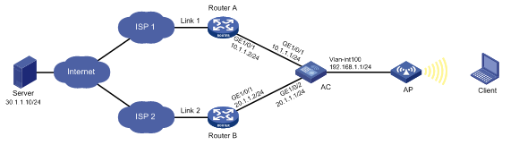
Configuration procedure
1. Configure IP addresses for interfaces.
[AC] interface gigabitethernet 1/0/1
[AC-GigabitEthernet1/0/1] ip address 10.1.1.1 24
[AC-GigabitEthernet1/0/1] quit
[AC] interface gigabitethernet 1/0/2
[AC-GigabitEthernet1/0/2] ip address 20.1.1.1 24
[AC-GigabitEthernet1/0/2] quit
2. Configure a link group:
# Create the ICMP-type NQA template t1, and configure the NQA client to send the probe result to the feature that uses the template on a per-probe basis.
[AC-nqatplt-icmp-t1] reaction trigger per-probe
[AC-nqatplt-icmp-t1] quit
# Specify the default proximity probe method as t1, and set the network delay weight for proximity calculation to 200.
[AC-lb-proximity] match default probe t1
[AC-lb-proximity] rtt weight 200
[AC-lb-proximity] quit
# Create the link group lg, and enable the proximity feature.
[AC] loadbalance link-group lg
[AC-lb-lgroup-lg] proximity enable
# Disable the NAT feature.
[AC-lb-lgroup-lg] transparent enable
[AC-lb-lgroup-lg] quit
3. Configure links:
# Create the link link1 with next hop address 10.1.1.2, and add it to the link group lg.
[AC-lb-link-link1] router ip 10.1.1.2
[AC-lb-link-link1] link-group lg
[AC-lb-link-link1] quit
# Create the link link2 with next hop address 20.1.1.2, and add it to link group lg.
[AC-lb-link-link2] router ip 20.1.1.2
[AC-lb-link-link2] link-group lg
[AC-lb-link-link2] quit
4. Create the link-IP virtual server vs with VSIP 0.0.0.0/0, specify its default master link group lg, and enable the virtual server.
[AC] virtual-server vs type link-ip
[AC-vs-link-ip-vs] virtual ip address 0.0.0.0 0
[AC-vs-link-ip-vs] default link-group lg
[AC-vs-link-ip-vs] service enable
[AC-vs-link-ip-vs] quit
Verifying the configuration
# Display brief information about all links.
[AC] display loadbalance link brief
Link Route IP State VPN instance Link group
link1 10.1.1.2 Active lg
link2 20.1.1.2 Active lg
# Display detailed information about all link groups.
[AC] display loadbalance link-group
Link group: lg
Description:
Predictor: Round robin
Proximity: Enabled
NAT: Disabled
SNAT pool:
Failed action: Keep
Active threshold: Disabled
Slow-online: Disabled
Selected link: Disabled
Probe information:
Probe success criteria: All
Probe method:
t1
Total link: 2
Active link: 2
Link list:
Name State VPN instance Router IP Weight Priority
link1 Active 10.1.1.2 100 4
link2 Active 20.1.1.2 100 4
# Display detailed information about all virtual servers.
Virtual server: vs
Description:
Type: LINK-IP
State: Active
VPN instance:
Virtual IPv4 address: 0.0.0.0/0
Virtual IPv6 address: --
Port: 0
Primary link group: lg (in use)
Backup link group:
Sticky:
LB policy:
Connection limit: --
Rate limit:
Connections: --
Bandwidth: --
Inbound bandwidth: --
Outbound bandwidth: --
Bandwidth busy protection: Disabled
Interface bandwidth statistics: Disabled
# Display brief information about all IPv4 proximity entries.
[AC] display loadbalance proximity ip
IPv4 entries in total: 1
IPv4 address/Mask length Timeout Best link
------------------------------------------------------------
10.1.0.0/24 50 link1
Configuring transparent DNS proxies
About transparent DNS proxies
Working mechanism
As shown in Figure 12, intranet users of an enterprise can access external servers A and B through link 1 of ISP 1 and link 2 of ISP 2. External servers A and B provide the same services. All DNS requests of intranet users are forwarded to DNS server A, which returns the resolved IP address of external server A to the requesting users. In this way, all traffic of intranet users is forwarded on one link. Link congestion might occur.
The transparent DNS proxy feature can solve this problem by forwarding DNS requests to DNS servers in different ISPs. All traffic from intranet users is evenly distributed on multiple links. This feature can prevent link congestion and ensure service continuity upon a link failure.
Figure 12 Transparent DNS proxy working mechanism
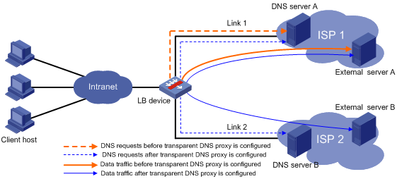
Workflow
The transparent DNS proxy is implemented by changing the destination IP address of DNS requests.
Figure 13 Transparent DNS proxy workflow
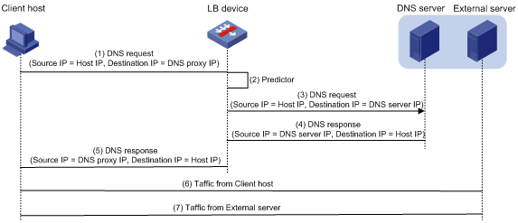
Table 3 Workflow description
|
Step |
Source IP address |
Destination IP address |
|
1. An intranet user on the client host sends a DNS request to the LB device. |
Host IP address |
IP address of DNS server A |
|
2. The LB device selects a DNS server to forward the DNS request according to the scheduling algorithm. |
N/A |
N/A |
|
3. The LB device changes the destination IP address of the DNS request as the IP address of the selected DNS server. |
Host IP address |
IP address of the selected DNS server |
|
4. The DNS server processes the DNS request and replies with a DNS response. |
IP address of the selected DNS server |
Host IP address |
|
5. The LB device changes the source IP address of the DNS response as the destination IP address of the DNS request. |
IP address of DNS server A |
Host IP address |
|
6. The intranet user accesses the external server according to the resolved IP address in the DNS response. |
Host IP address |
IP address of the external server |
|
7. The external server responds to the intranet user. |
IP address of the external server |
Host IP address |
Transparent DNS proxy on the LB device
The LB device distributes DNS requests to multiple links by changing the destination IP address of DNS requests.
As shown in Figure 14, the LB device contains the following elements:
· Transparent DNS proxy—The LB device performs transparent DNS proxy for a DNS request only when the port number of the DNS request matches the port number of the transparent DNS proxy.
· DNS server pool—A group of DNS servers.
· DNS server—Entity that processes DNS requests.
· Link—Physical link provided by an ISP.
· LB class—Classifies packets to implement load balancing based on packet type.
· LB action—Drops, forwards, or modifies packets.
· LB policy—Associates an LB class with an LB action. An LB policy can be referenced by the transparent DNS proxy.
Figure 14 Transparent DNS proxy on the LB device
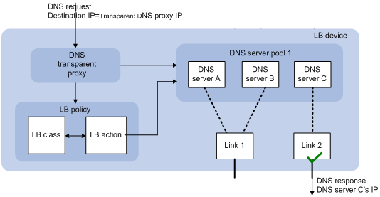
If the destination IP address and port number of a DNS request match those of the transparent DNS proxy, the LB device processes the DNS request as follows:
1. The LB device finds the DNS server pool associated with the transparent DNS proxy.
2. The LB device selects a DNS server according to the scheduling algorithm configured for the DNS server pool.
3. The LB device uses the IP address of the selected DNS server as the destination IP address of the DNS request, and sends the request to the DNS server.
4. The DNS server receives and processes the DNS request, and replies with a DNS response.
The intranet user can now access the external server after receiving the DNS response.
Transparent DNS proxy configuration task list
|
Tasks at a glance |
|
(Required.) Configuring a transparent DNS proxy |
|
(Required.) Configuring a DNS server pool |
|
(Required.) Configuring a DNS server |
|
(Required.) Configuring a link |
|
(Optional.) Configuring an LB class |
|
(Optional.) Configuring an LB action |
|
(Optional.) Configuring an LB policy |
|
(Optional.) Configuring a sticky group |
Configuring a transparent DNS proxy
By configuring a transparent DNS proxy, you can load balance DNS requests that match the transparent DNS proxy.
Configuration task list
|
Tasks at a glance |
Remarks |
|
(Required.) Creating a transparent DNS proxy |
N/A |
|
(Required.) Specifying an IP address and port number |
N/A |
|
(Required.) Perform at least one of the following tasks: |
If you configure both tasks, a DNS request is first processed by the LB policy. If the DNS request fails to match the LB policy, it is processed by the DNS server pool. |
|
(Optional.) Enabling the link protection feature |
N/A |
|
(Required.) Enabling the transparent DNS proxy |
N/A |
Creating a transparent DNS proxy
|
Step |
Command |
Remarks |
|
1. Enter system view. |
system-view |
N/A |
|
2. Create a transparent DNS proxy and enter its view. |
loadbalance dns-proxy dns-proxy-name type udp |
By default, no transparent DNS proxies exist. |
Specifying an IP address and port number
Restrictions and guidelines
As a best practice, configure an all-zero IP address for a transparent DNS proxy. In this case, all DNS requests are processed by the transparent DNS proxy.
Procedure
|
Step |
Command |
Remarks |
|
1. Enter system view. |
system-view |
N/A |
|
2. Enter transparent DNS proxy view. |
loadbalance dns-proxy dns-proxy-name |
N/A |
|
3. Specify an IP address for the transparent DNS proxy. |
· Specify an IPv4 address: · Specify an IPv6 address: |
Use either command. By default, no IP address is specified for a transparent DNS proxy. |
|
4. Specify the port number for the transparent DNS proxy. |
port port-number |
By default, the port number is 53 for a transparent DNS proxy. |
Specifying the default DNS server pool
|
Step |
Command |
Remarks |
|
1. Enter system view. |
system-view |
N/A |
|
2. Enter transparent DNS proxy view. |
loadbalance dns-proxy dns-proxy-name |
N/A |
|
3. Specify the default DNS server pool for the transparent DNS proxy. |
default dns-server-pool pool-name [ sticky sticky-name ] |
By default, no default DNS server pool is specified for a transparent DNS proxy. |
Specifying an LB policy
About specifying an LB policy
By referencing an LB policy, the transparent DNS proxy load balances matching DNS requests based on the packet contents. For more information about configuring an LB policy, see "Configuring an LB policy."
Procedure
|
Step |
Command |
Remarks |
|
1. Enter system view. |
system-view |
N/A |
|
2. Enter transparent DNS proxy view. |
loadbalance dns-proxy dns-proxy-name |
N/A |
|
3. Specify an LB policy for the transparent DNS proxy. |
lb-policy policy-name |
By default, a transparent DNS proxy does not reference any LB policies. |
Enabling the link protection feature
About the link protection feature
This feature enables a transparent DNS proxy to select a DNS server based on the link bandwidth ratio. If the bandwidth ratio of a link is exceeded, the DNS server is not selected.
If the traffic volume on the link to a DNS server exceeds the maximum expected bandwidth multiplied by the bandwidth ratio, the DNS server is busy and will not be selected. If the traffic volume drops below the maximum expected bandwidth multiplied by the bandwidth recovery ratio, the DNS server participates in scheduling again. For more information about setting the bandwidth ratio, see "Setting the bandwidth ratio and maximum expected bandwidth."
Procedure
|
Step |
Command |
Remarks |
|
1. Enter system view. |
system-view |
N/A |
|
2. Enter transparent DNS proxy view. |
loadbalance dns-proxy dns-proxy-name |
N/A |
|
3. Enable the link protection feature. |
bandwidth busy-protection enable |
By default, the link protection feature is disabled. |
Enabling the transparent DNS proxy
About enabling the transparent DNS proxy
After configuring a transparent DNS proxy, you must enable the transparent DNS proxy for it to work.
Procedure
|
Step |
Command |
Remarks |
|
1. Enter system view. |
system-view |
N/A |
|
2. Enter transparent DNS proxy view. |
loadbalance dns-proxy dns-proxy-name |
N/A |
|
3. Enable the transparent DNS proxy. |
service enable |
By default, a transparent DNS proxy is disabled. |
Configuring a DNS server pool
By configuring a DNS server pool, you can perform centralized management on DNS servers that have similar functions.
Creating a DNS server pool
|
Step |
Command |
Remarks |
|
1. Enter system view. |
system-view |
N/A |
|
2. Create a DNS server pool and enter its view. |
loadbalance dns-server-pool pool-name |
By default, no DNS server pools exist. |
|
3. (Optional.) Set a description for the DNS server pool. |
description text |
By default, no description is set for a DNS server pool. |
Scheduling DNS servers
About scheduling DNS servers
Perform this task to specify a scheduling algorithm for a DNS server pool and specify the number of DNS servers to participate in scheduling. The LB device calculates the DNS servers to process DNS requests based on the following scheduling algorithms:
· Source IP address hash algorithm—Hashes the source IP address of DNS requests and distributes DNS requests to different DNS servers according to the hash values. This hash algorithm ensures that DNS requests with the same source IP address are distributed to the same DNS server.
· Source IP address and port hash algorithm—Hashes the source IP address and port number of DNS requests and distributes DNS requests to different DNS servers according to the hash values. This hash algorithm ensures that DNS requests with the same source IP address and port number are distributed to the same DNS server.
· Destination IP address hash algorithm—Hashes the destination IP address of DNS requests and distributes DNS requests to different DNS servers according to the hash values. This hash algorithm ensures that DNS requests with the same destination IP address are distributed to the same DNS server.
· Random algorithm—Distributes DNS requests to DNS servers randomly.
· Weighted round-robin algorithm—Distributes DNS requests to DNS servers in a round-robin manner according to the weights of DNS servers. For example, you can assign weight values 2 and 1 to DNS server A and DNS server B, respectively. This algorithm distributes two DNS requests to DNS server A and then distributes one DNS request to DNS server B. This algorithm applies to scenarios where DNS servers have different performance and bear similar load for each session.
· Bandwidth algorithm—Distributes DNS requests to DNS servers according to the weights and remaining bandwidths of DNS servers. When the remaining bandwidths of two DNS servers are the same, this algorithm is equivalent to the round-robin algorithm. When the weights of two DNS servers are the same, this algorithm always distributes DNS requests to the DNS server that has larger remaining bandwidth.
· Maximum bandwidth algorithm—Distributes DNS requests always to an idle DNS server that has the largest remaining bandwidth.
Procedure
|
Step |
Command |
Remarks |
|
1. Enter system view. |
system-view |
N/A |
|
2. Enter DNS server pool view. |
loadbalance dns-server-pool pool-name |
N/A |
|
3. Specify a scheduling algorithm for the DNS server pool. |
predictor { random | round-robin | { bandwidth | max-bandwidth } [ inbound | outbound ] } |
By default, the scheduling algorithm for a DNS server pool is weighted round robin. |
|
4. Specify the number of DNS servers to participate in scheduling. |
selected-server min min-number max max-number |
By default, the DNS servers with the highest priority participate in scheduling. |
Configuring health monitoring
About configuring health monitoring
Perform this task to enable health monitoring to detect the availability of DNS servers in a DNS server pool.
Restrictions and guidelines
The health monitoring configuration in DNS server view takes precedence over the configuration in DNS server pool view.
Procedure
|
Step |
Command |
Remarks |
|
1. Enter system view. |
system-view |
N/A |
|
2. Enter DNS server pool view. |
loadbalance dns-server-pool pool-name |
N/A |
|
3. Specify a health monitoring method for the DNS server pool. |
probe template-name |
By default, no health monitoring method is specified for a DNS server pool. |
|
4. Specify the health monitoring success criteria for the DNS server pool. |
success-criteria { all | at-least min-number } |
By default, health monitoring succeeds only when all the specified health monitoring methods succeed. |
Configuring a DNS server
Perform this task to configure an entity on the LB device for processing DNS requests. DNS servers configured on the LB device correspond to DNS servers in ISP networks. A DNS server can belong to only one DNS server pool. A DNS server pool can contain multiple DNS servers.
DNS server configuration task list
|
Tasks at a glance |
|
(Required.) Creating a DNS server and specifying a DNS server pool |
|
(Required.) Specifying an IP address and port number |
|
(Required.) Associating a link with a DNS server |
|
(Optional.) Setting a weight and priority |
|
(Optional.) Configuring health monitoring |
Creating a DNS server and specifying a DNS server pool
|
Step |
Command |
Remarks |
|
1. Enter system view. |
system-view |
N/A |
|
2. Create a DNS server and enter its view. |
loadbalance dns-server dns-server-name |
By default, no DNS servers exist. |
|
3. (Optional.) Set a description for the DNS server. |
description text |
By default, no description is set for a DNS server. |
|
4. Specify a DNS server pool for the DNS server. |
dns-server-pool pool-name |
By default, a DNS server does not belong to any DNS server pool. |
Specifying an IP address and port number
|
Step |
Command |
Remarks |
|
1. Enter system view. |
system-view |
N/A |
|
2. Enter DNS server view. |
loadbalance dns-server dns-server-name |
N/A |
|
3. Specify an IP address for the DNS server. |
· Specify an IPv4 address: · Specify an IPv6 address: |
By default, no IPv4 or IPv6 address is specified for a DNS server. |
|
4. Specify the port number for the DNS server. |
port port-number |
By default, the port number of a DNS server is 0. Packets use their own port numbers. |
Associating a link with a DNS server
Restrictions and guidelines
A DNS server can be associated with only one link. A link can be associated with multiple DNS servers.
Procedure
|
Step |
Command |
Remarks |
|
1. Enter system view. |
system-view |
N/A |
|
2. Enter DNS server view. |
loadbalance dns-server dns-server-name |
N/A |
|
3. Associate a link with the DNS server. |
link link-name |
By default, no link is associated with a DNS server. |
Setting a weight and priority
About setting a weight and priority
Perform this task to set a weight for the weighted round robin algorithm and bandwidth algorithm of a DNS server, and set the scheduling priority in the DNS server pool for the DNS server.
Procedure
|
Step |
Command |
Remarks |
|
1. Enter system view. |
system-view |
N/A |
|
2. Enter DNS server view. |
loadbalance dns-server dns-server-name |
N/A |
|
3. Set a weight for the DNS server. |
weight weight-value |
By default, the weight of a DNS server is 100. |
|
4. Set a priority for the DNS server. |
priority priority |
By default, the priority of a DNS server is 4. |
Configuring health monitoring
About configuring health monitoring
Perform this task to enable health monitoring to detect the availability of a DNS server.
Restrictions and guidelines
The health monitoring configuration in DNS server view takes precedence over the configuration in DNS server pool view.
Procedure
|
Step |
Command |
Remarks |
|
1. Enter system view. |
system-view |
N/A |
|
2. Enter DNS server view. |
loadbalance dns-server dns-server-name |
N/A |
|
3. Specify a health monitoring method for the DNS server. |
probe template-name |
By default, no health monitoring method is specified for a DNS server. |
|
4. Specify the health monitoring success criteria for the DNS server. |
success-criteria { all | at-least min-number } |
By default, health monitoring succeeds only when all the specified health monitoring methods succeed. |
Configuring a link
A link is a physical link provided by an ISP. You can guide traffic forwarding by specifying an outbound next hop for a link. You can enhance link performance by configuring the maximum bandwidth, health monitoring, bandwidth ratio, and maximum expected bandwidth.
Link configuration task list
|
Tasks at a glance |
|
(Required.) Creating a link |
|
(Required.) Specifying an outbound next hop for a link |
|
(Optional.) Configuring the maximum bandwidth |
|
(Optional.) Configuring health monitoring |
|
(Optional.) Setting the bandwidth ratio and maximum expected bandwidth |
Creating a link
|
Step |
Command |
Remarks |
|
1. Enter system view. |
system-view |
N/A |
|
2. Create a link and enter link view. |
loadbalance link link-name |
By default, no links exist. |
|
3. (Optional.) Set a description for the link. |
description text |
By default, no description is set for a link. |
Specifying an outbound next hop for a link
|
Step |
Command |
Remarks |
|
1. Enter system view. |
system-view |
N/A |
|
2. Enter link view. |
loadbalance link link-name |
N/A |
|
3. Specify an outbound next hop for the link. |
· Specify the IPv4 address of the
outbound next hop: · Specify the IPv6 address of the
outbound next hop: |
By default, no outbound next hop is specified for a link. |
Configuring the maximum bandwidth
|
Step |
Command |
Remarks |
|
1. Enter system view. |
system-view |
N/A |
|
2. Enter link view. |
loadbalance link link-name |
N/A |
|
3. Set the maximum bandwidth for the link. |
rate-limit bandwidth [ inbound | outbound ] bandwidth-value |
By default, the maximum bandwidth for a link is not limited. |
Configuring health monitoring
About configuring health monitoring
Perform this task to enable health monitoring to detect the availability of a link.
Procedure
|
Step |
Command |
Remarks |
|
1. Enter system view. |
system-view |
N/A |
|
2. Enter link view. |
loadbalance link link-name |
N/A |
|
3. Specify a health monitoring method for the link. |
probe template-name |
By default, no health monitoring method is specified for a link. |
|
4. Specify the health monitoring success criteria for the link. |
success-criteria { all | at-least min-number } |
By default, the health monitoring succeeds only when all the specified health monitoring methods succeed. |
Setting the bandwidth ratio and maximum expected bandwidth
About setting the bandwidth ratio and maximum expected bandwidth
When the traffic exceeds the maximum expected bandwidth multiplied by the bandwidth ratio of a link, new traffic (traffic that does not match any sticky entries) is not distributed to the link. When the traffic drops below the maximum expected bandwidth multiplied by the bandwidth recovery ratio of the link, the link participates in scheduling again.
In addition to being used for link protection, the maximum expected bandwidth is used for remaining bandwidth calculation in the bandwidth algorithm and maximum bandwidth algorithm.
Procedure
|
Step |
Command |
Remarks |
|
1. Enter system view. |
system-view |
N/A |
|
2. Enter link view. |
loadbalance link link-name |
N/A |
|
3. Set the bandwidth ratio. |
bandwidth [ inbound | outbound ] busy-rate busy-rate-number [ recovery recovery-rate-number ] |
By default, the total bandwidth ratio is 70. |
|
4. Set the maximum expected bandwidth. |
max-bandwidth [ inbound | outbound ] bandwidth-value |
By default, the maximum expected bandwidth is not limited. |
Configuring an LB class
An LB class classifies packets by comparing packets against specific rules. Matching packets are further processed by LB actions. You can create a maximum of 65535 rules for an LB class.
LB class configuration task list
|
Tasks at a glance |
Remarks |
|
(Required.) Creating an LB class |
N/A |
|
(Required.) Creating a match rule: · Creating a match rule that references an LB class · Creating a source IP address match rule |
Choose a minimum of one of the tasks. |
Creating an LB class
|
Step |
Command |
Remarks |
|
1. Enter system view. |
system-view |
N/A |
|
2. Create a DNS LB class, and enter LB class view. |
loadbalance class class-name type dns [ match-all | match-any ] |
By default, no LB classes exist. When you create an LB class, you must specify an LB class type. You can enter an existing LB class view without specifying the type of the LB class. |
|
3. (Optional.) Set a description for the LB class. |
description text |
By default, no description is set for an LB class. |
Creating a match rule that references an LB class
|
Step |
Command |
Remarks |
|
1. Enter system view. |
system-view |
N/A |
|
2. Enter LB class view. |
loadbalance class class-name |
N/A |
|
3. Create a match rule that references an LB class. |
match [ match-id ] class class-name |
By default, an LB class does not have any match rules. |
Creating a source IP address match rule
|
Step |
Command |
Remarks |
|
1. Enter system view. |
system-view |
N/A |
|
2. Enter LB class view. |
loadbalance class class-name |
N/A |
|
3. Create a source IP address match rule. |
match [ match-id ] source { ip address ipv4-address [ mask-length | mask ] | ipv6 address ipv6-address [ prefix-length ] } |
By default, an LB class does not have any match rules. |
Creating a destination IP address match rule
|
Step |
Command |
Remarks |
|
1. Enter system view. |
system-view |
N/A |
|
2. Enter LB class view. |
loadbalance class class-name |
N/A |
|
3. Create a destination IP address match rule. |
match [ match-id ] destination { ip address ipv4-address [ mask-length | mask ] | ipv6 address ipv6-address [ prefix-length ] } |
By default, an LB class does not have any match rules. |
Creating an ACL match rule
Restrictions and guidelines
If the specified ACL does not exist, the ACL match rule does not take effect.
Procedure
|
Step |
Command |
Remarks |
|
1. Enter system view. |
system-view |
N/A |
|
2. Enter LB class view. |
loadbalance class class-name |
N/A |
|
3. Create an ACL match rule. |
match [ match-id ] acl [ ipv6 ] { acl-number | name acl-name } |
By default, an LB class does not have any match rules. |
Creating a domain name match rule
|
Step |
Command |
Remarks |
|
1. Enter system view. |
system-view |
N/A |
|
2. Enter LB class view. |
loadbalance class class-name |
N/A |
|
3. Create a domain name match rule. |
match [ match-id ] domain-name domain-name |
By default, an LB class does not have any match rules. |
Configuring an LB action
About LB actions
LB actions include the following modes:
· Forwarding mode—Determines whether and how to forward packets. If no forwarding action is specified, packets are dropped.
· Modification mode—Modifies packets. To prevent the LB device from dropping the modified packets, the modification action must be used together with a forwarding action.
If you create an LB action without specifying any of the previous action modes, packets are dropped.
LB action configuration task list
|
Tasks at a glance |
Remarks |
|
(Required.) Creating an LB action |
N/A |
|
(Optional.) Configuring a forwarding LB action: · Configuring the forwarding mode · Specifying a DNS server pool for guiding packet forwarding |
Choose one of the tasks. The first three tasks are mutually exclusive. Configuring one task automatically cancels the other task that you have configured. |
|
(Optional.) Configuring a modification LB action: · Configuring the ToS field in IP packets sent to the DNS server |
N/A |
Creating an LB action
|
Step |
Command |
Remarks |
|
1. Enter system view. |
system-view |
N/A |
|
2. Create a DNS LB action and enter LB action view. |
loadbalance action action-name type dns |
By default, no LB actions exist. When you create an LB action, you must specify the LB action type. You can enter an existing LB action view without specifying the type of the LB action. |
|
3. (Optional.) Set a description for the LB action. |
description text |
By default, no description is set for an LB action. |
Configuring a forwarding LB action
About forwarding LB actions
Three forwarding LB action types are available:
· Forward—Forwards matching packets.
· Specify a DNS server pool for guiding packet forwarding.
· Skip the current transparent DNS proxy—Skips the current transparent DNS proxy and match the next transparent DNS proxy or virtual server.
· Match the next rule upon failure to find a DNS server—If the device fails to find a DNS server according to the LB action, it matches the packet with the next rule in the LB policy.
Configuring the forwarding mode
|
Step |
Command |
Remarks |
|
1. Enter system view. |
system-view |
N/A |
|
2. Enter DNS LB action view. |
loadbalance action action-name |
N/A |
|
3. Configure the forwarding mode. |
forward all |
By default, the forwarding mode is to discard packets. |
Specifying a DNS server pool for guiding packet forwarding
|
Step |
Command |
Remarks |
|
1. Enter system view. |
system-view |
N/A |
|
2. Enter DNS LB action view. |
loadbalance action action-name |
N/A |
|
3. Specify a DNS server pool for guiding packet forwarding. |
dns-server-pool pool-name [ sticky sticky-name ] |
By default, no DNS server pool is specified for guiding packet forwarding. |
Skipping the current transparent DNS proxy
|
Step |
Command |
Remarks |
|
1. Enter system view. |
system-view |
N/A |
|
2. Enter DNS LB action view. |
loadbalance action action-name |
N/A |
|
3. Skip the current transparent DNS proxy. |
skip current-dns-proxy |
By default, the forwarding mode is to discard packets. |
Matching the next rule upon failure to find a DNS server
Perform this task to enable packets to match the next rule in an LB policy when no DNS servers are available for the current LB action.
To match the next rule upon failure to find a DNS server:
|
Step |
Command |
Remarks |
|
1. Enter system view. |
system-view |
N/A |
|
2. Enter DNS LB action view. |
loadbalance action action-name |
N/A |
|
3. Match the next rule upon failure to find a DNS server. |
fallback-action continue |
By default, the next rule is not matched (packets are dropped) when no DNS servers are available for an LB action. |
Configuring the ToS field in IP packets sent to the DNS server
|
Step |
Command |
Remarks |
|
1. Enter system view. |
system-view |
N/A |
|
2. Enter DNS LB action view. |
loadbalance action action-name |
N/A |
|
3. Configure the ToS field in IP packets sent to the DNS server. |
set ip tos tos-number |
By default, the ToS field in IP packets sent to the DNS server is not changed. |
Configuring an LB policy
LB policy configuration task list
|
Tasks at a glance |
|
(Required.) Creating an LB policy |
|
(Required.) Specifying an LB action |
|
(Required.) Specifying the default LB action |
Creating an LB policy
|
Step |
Command |
Remarks |
|
1. Enter system view. |
system-view |
N/A |
|
2. Create a DNS LB policy and enter LB action view. |
loadbalance policy policy-name type dns |
By default, no LB policies exist. When you create an LB policy, you must specify the LB policy type. You can enter an existing LB policy view without specifying the type of the LB policy. |
|
3. (Optional.) Set a description for the LB policy. |
description text |
By default, no description is set for an LB policy. |
Specifying an LB action
Restrictions and guidelines
A DNS LB policy can reference only DNS LB classes and DNS LB actions.
Procedure
|
Step |
Command |
Remarks |
|
1. Enter system view. |
system-view |
N/A |
|
2. Enter DNS LB policy view. |
loadbalance policy policy-name |
N/A |
|
3. Specify an LB action for an LB class. |
class class-name [ insert-before before-class-name ] action action-name |
By default, no LB action is specified for an LB class. |
Specifying the default LB action
Restrictions and guidelines
The default LB action takes effect on packets that do not match any LB classes.
A DNS LB policy can reference only a DNS LB action as the default LB action.
Procedure
|
Step |
Command |
Remarks |
|
1. Enter system view. |
system-view |
N/A |
|
2. Enter DNS LB policy view. |
loadbalance policy policy-name |
N/A |
|
3. Specify the default LB action. |
default-class action action-name |
By default, no default LB action is specified. |
Configuring a sticky group
A sticky group uses a sticky method to distribute similar sessions to the same DNS server according to sticky entries. The sticky method applies to the first packet of a session. Other packets of the session are distributed to the same DNS server.
Sticky group configuration task list
|
Tasks at a glance |
|
(Required.) Creating a sticky group |
|
(Required.) Configuring the IP sticky method |
|
(Optional.) Configuring the timeout time for sticky entries |
Creating a sticky group
|
Step |
Command |
Remarks |
||
|
1. Enter system view. |
system-view |
N/A |
||
|
2. Create an address- and port-type sticky group and enter sticky group view. |
sticky-group group-name type address-port |
By default, no sticky groups exist. When you create a sticky group, you must specify a type. You can enter an existing sticky group view without specifying the type of the group. |
||
|
3. (Optional.) Set a description for the sticky group. |
description text |
By default, no description is set for a sticky group. |
||
Configuring the IP sticky method
|
Step |
Command |
Remarks |
|
1. Enter system view. |
system-view |
N/A |
|
2. Enter sticky group view. |
sticky-group group-name |
N/A |
|
3. Configure the IP sticky method. |
· Configure an IPv4 sticky method: · Configure an IPv6 sticky method: |
By default, no sticky methods exist. |
Configuring the timeout time for sticky entries
|
Step |
Command |
Remarks |
|
1. Enter system view. |
system-view |
N/A |
|
2. Enter sticky group view. |
sticky-group group-name |
N/A |
|
3. Configure the timeout time for sticky entries. |
timeout timeout-value |
By default, the timeout time for sticky entries is 60 seconds. |
Displaying and maintaining transparent DNS proxy
Execute display commands in any view and reset commands in user view.
|
Task |
Command |
|
Display DNS server pool information. |
display loadbalance dns-server-pool [ brief | name pool-name ] |
|
Display DNS server information. |
display loadbalance dns-server [ brief | name dns-server-name ] |
|
Display DNS server statistics. |
display loadbalance dns-server statistics [ name dns-server-name ] |
|
Display transparent DNS proxy information. |
display loadbalance dns-proxy [ brief | name dns-proxy-name ] |
|
Display transparent DNS proxy statistics. |
display loadbalance dns-proxy statistics [ name dns-proxy-name ] |
|
Display link information. |
display loadbalance link [ brief | name link-name ] |
|
Display link statistics. |
display loadbalance link statistics [ name link-name ] |
|
Display LB class information. |
display loadbalance class [ name class-name ] |
|
Display LB action information. |
display loadbalance action [ name action-name ] |
|
Display LB policy information. |
display loadbalance policy [ name policy-name ] |
|
Display sticky entry information for transparent DNS proxies. |
display sticky dns-proxy [ dns-proxy-name ] [ class class-name | default-class | default-dns-server-pool ] |
|
Display sticky group information. |
display sticky-group [ name group-name ] |
|
Clear DNS server statistics. |
reset loadbalance dns-server statistics [ dns-server-name ] |
|
Clear transparent DNS proxy statistics. |
reset loadbalance dns-proxy statistics [ dns-proxy-name ] |
|
Clear link statistics. |
reset loadbalance link statistics [ link-name ] |
Transparent DNS proxy configuration examples
Network requirements
In Figure 15, ISP 1 and ISP 2 provide two links with the same bandwidth: Link 1 and Link 2. The IP address of the DNS server of ISP 1 is 10.1.2.100. The IP address of the DNS server of ISP 2 is 20.1.2.100. Intranet users use domain name www.abc.com to access Web server A and Web server B.
Configure a transparent DNS proxy on the AC to evenly distribute user traffic to Link 1 and Link 2.
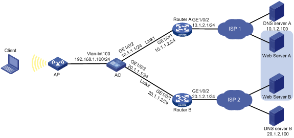
Configuration procedure
1. Configure IP addresses for interfaces.
<AC> system-view
[AC] interface gigabitethernet 1/0/1
[AC-GigabitEthernet1/0/1] ip address 192.168.1.100 24
[AC-GigabitEthernet1/0/1] quit
[AC] interface gigabitethernet 1/0/2
[AC-GigabitEthernet1/0/2] ip address 10.1.1.1 24
[AC-GigabitEthernet1/0/2] quit
[AC] interface gigabitethernet 1/0/3
[AC-GigabitEthernet1/0/3] ip address 20.1.1.1 24
[AC-GigabitEthernet1/0/3] quit
2. Configure links:
# Create the link link1 with next hop address 10.1.1.2.
[AC] loadbalance link link1
[AC-lb-link-link1] router ip 10.1.1.2
[AC-lb-link-link1] quit
# Create the link link2 with next hop address 20.1.1.2.
[AC] loadbalance link link2
[AC-lb-link-link2] router ip 20.1.1.2
[AC-lb-link-link2] quit
3. Create a DNS server pool named dsp.
[AC] loadbalance dns-server-pool dsp
[AC-lb-dspool-dsp] quit
4. Configure DNS servers:
# Create a DNS server named ds1, configure its IP address as 10.1.2.100, assign it to DNS server pool dsp, and associate it with link link1.
[AC] loadbalance dns-server ds1
[AC-lb-ds-ds1] ip address 10.1.2.100
[AC-lb-ds-ds1] dns-server-pool dsp
[AC-lb-ds-ds1] link link1
[AC-lb-ds-ds1] quit
# Create a DNS server named ds2, configure its IP address as 20.1.2.100, assign it to DNS server pool dsp, and associate it with link link2.
[AC] loadbalance dns-server ds2
[AC-lb-ds-ds2] ip address 20.1.2.100
[AC-lb-ds-ds2] dns-server-pool dsp
[AC-lb-ds-ds2] link link2
[AC-lb-ds-ds2] quit
5. Configure a transparent DNS proxy:
# Create a UDP transparent DNS proxy named dns-proxy1, configure its IP address as 0.0.0.0, specify DNS server pool dsp as its default DNS server pool, and enable the transparent DNS proxy.
[AC] loadbalance dns-proxy dns-proxy1 type udp
[AC-lb-dp-udp-dp] ip address 0.0.0.0 0
[AC-lb-dp-udp-dp] default dns-server-pool dsp
[AC-lb-dp-udp-dp] service enable
[AC-lb-dp-udp-dp] quit
Verifying the configuration
# Display brief information about all DNS servers.
[AC] display loadbalance dns-server brief
DNS server Address Port Link State DNS server pool
ds1 10.1.2.100 0 link1 Active dsp
ds2 20.1.2.100 0 link2 Active dsp
# Display detailed information about all DNS server pools.
[AC] display loadbalance dns-server-pool
DNS server pool: dsp
Description:
Predictor: Round robin
Selected server: Disabled
Probe information:
Probe success criteria: All
Probe method:
Total DNS servers: 2
Active DNS servers: 2
DNS server list:
Name State Address port Link Weight Priority
ds1 Active 10.1.2.100 0 link1 100 4
ds2 Active 20.1.2.100 0 link2 100 4
# Display detailed information about all transparent DNS proxies.
[AC] display loadbalance dns-proxy
DNS proxy: dns-proxy1
Type: UDP
State: Active
Service state: Enabled
VPN instance:
IPv4 address: 1.1.1.0/24
IPv6 address: --
Port: 53
DNS server pool: dsp
Sticky:
LB policy:
Bandwidth busy protection: Disabled
After you complete the previous configuration, the AC can evenly distribute DNS requests to DNS server A and DNS server B. Then, intranet user traffic is evenly distributed to Link 1 and Link 2.
A
ACL
DNS transparent proxy match rule (ACL), 68
outbound link load balancing match rule (ACL), 43
action
DNS transparent proxy forwarding LB action, 70
outbound link load balancing forwarding LB action, 45
active
interface backup (active/standby mode w/o traffic thresholds), 4
interface backup active/standby mode, 1
interface backup configuration (active/standby), 6
interface backup configuration (active/standby+Track association), 8
ALG
outbound link load balancing SNMP notification enable, 50
application
interface backup+Track association, 5
Track+application module association, 17
Track+application module collaboration, 12
Track+EAA association, 20
Track+interface backup association, 18
Track+static routing association, 18
associating
DNS transparent proxy link with DNS server, 64
interface backup configuration (active/standby+Track association), 8
interface backup+Track association, 5
Track+application module, 17
Track+detection modules, 13
Track+EAA, 20
Track+interface backup, 18
Track+interface management, 13
Track+NQA, 13
Track+route management, 14
Track+static routing, 18
availability
outbound link load balancing availability criteria, 30
B
backing up
Track+interface backup association, 18
bandwidth
DNS transparent proxy link bandwidth ratio+max expected bandwidth, 66
DNS transparent proxy maximum link bandwidth, 66
outbound link load balancing link bandwidth ratio+max expected bandwidth, 37
outbound link load balancing link bandwidth+connection parameter, 36
outbound link load balancing virtual server bandwidth+connection parameter, 40
outbound link load balancing virtual server link bandwidth statistics collection, 41
bandwidth algorithm
scheduling DNS transparent proxy DNS server, 61
C
class
DNS transparent proxy match rule (LB class), 67
outbound link load balancing match rule (LB class), 42
classifying
DNS transparent proxy LB class, 67
outbound link load balancing LB class, 42
collaborating
static routing+Track+NQA collaboration, 20
Track configuration, 11, 12
Track+application modules, 12
Track+detection modules, 11
configuring
DNS transparent proxy, 56, 59, 74
DNS transparent proxy DNS server health monitoring, 64
DNS transparent proxy DNS server pool health monitoring, 62
DNS transparent proxy forwarding LB action, 70
DNS transparent proxy forwarding mode, 70
DNS transparent proxy IP packet ToS field, 71
DNS transparent proxy IP sticky method, 73
DNS transparent proxy LB action, 69
DNS transparent proxy LB class, 67
DNS transparent proxy LB policy, 71
DNS transparent proxy link health monitoring, 66
DNS transparent proxy maximum link bandwidth, 66
DNS transparent proxy sticky entry timeout time, 73
DNS transparent proxy sticky group, 72
high availability DNS transparent proxy DNS server, 63
high availability DNS transparent proxy DNS server pool, 61
high availability DNS transparent proxy link, 65
high availability link group, 29
high availability link load balancing link, 34
high availability link load balancing link group, 29
high availability link load balancing SNAT, 31
interface backup, 1, 3, 6
interface backup (active/standby mode w/o traffic thresholds), 4
interface backup (active/standby mode), 4
interface backup (active/standby), 6
interface backup (active/standby+Track association), 8
interface backup (load-shared), 5, 8
outbound link load balancing, 27, 28, 52, 52
outbound link load balancing ALG, 50
outbound link load balancing forwarding LB action, 45
outbound link load balancing forwarding mode, 45
outbound link load balancing health monitoring, 32
outbound link load balancing IP packet ToS field, 46, 49
outbound link load balancing IP sticky method, 48
outbound link load balancing ISP information, 50, 50
outbound link load balancing LB action, 44
outbound link load balancing LB class, 42
outbound link load balancing LB policy, 46
outbound link load balancing link bandwidth+connection parameter, 36
outbound link load balancing link health monitoring, 36
outbound link load balancing parameter profile, 49
outbound link load balancing proximity, 33
outbound link load balancing sticky entry timeout time, 48
outbound link load balancing sticky group, 47
outbound link load balancing virtual server, 38
outbound link load balancing virtual server bandwidth+connection parameter, 40
static routing+Track+NQA collaboration, 20
Track, 11, 12
cost
outbound link load balancing link proximity link cost, 37
creating
DNS transparent proxy LB action, 69
DNS transparent proxy LB class, 67
DNS transparent proxy LB policy, 71
DNS transparent proxy match rule (ACL), 68
DNS transparent proxy match rule (destination IP address), 68
DNS transparent proxy match rule (LB class), 67
DNS transparent proxy match rule (source IP address), 68
DNS transparent proxy sticky group, 73
high availability DNS transparent proxy, 59
high availability DNS transparent proxy DNS server, 63
high availability DNS transparent proxy DNS server pool, 61
high availability DNS transparent proxy domain name match rule, 69
high availability DNS transparent proxy link, 65
high availability link load balancing application group match rule, 44
high availability link load balancing domain name match rule, 43
high availability link load balancing link, 35
high availability link load balancing link group, 29
outbound link load balancing LB action, 45
outbound link load balancing LB class, 42
outbound link load balancing LB policy, 46
outbound link load balancing match rule (ACL), 43
outbound link load balancing match rule (destination IP address), 43
outbound link load balancing match rule (ISP), 44
outbound link load balancing match rule (LB class), 42
outbound link load balancing match rule (source IP address), 42
outbound link load balancing parameter profile, 49
outbound link load balancing sticky group, 48
outbound link load balancing virtual server, 38
criteria
outbound link load balancing availability criteria, 30
D
default
load balancing DNS transparent proxy default DNS server pool, 60
outbound link load balancing virtual link group, 39
destination IP address
scheduling DNS transparent proxy DNS server, 61
detecting
interface backup configuration, 6
interface backup configuration (active/standby), 6
interface backup configuration (active/standby+Track association), 8
interface backup configuration (load-shared), 8
outbound link load balancing proximity, 33
Track configuration, 11
Track+application module collaboration, 12
Track+detection module association, 13
Track+detection module collaboration, 11
Track+interface management association, 13
Track+NQA association, 13
Track+route management association, 14
device
associating DNS transparent proxy link with DNS server, 64
DNS transparent proxy configuration, 56, 74
DNS transparent proxy DNS server health monitoring, 64
DNS transparent proxy DNS server IP address+port number, 63
DNS transparent proxy DNS server pool health monitoring, 62
DNS transparent proxy DNS server weight+priority configuration, 64
DNS transparent proxy IP address+port number, 59
DNS transparent proxy LB action, 69
DNS transparent proxy LB action creation, 69
DNS transparent proxy LB class, 67
DNS transparent proxy link health monitoring, 66
high availability DNS transparent proxy creation, 59
high availability DNS transparent proxy DNS server, 63
high availability DNS transparent proxy DNS server creation, 63
high availability DNS transparent proxy DNS server pool, 61, 63
high availability DNS transparent proxy DNS server pool creation, 61
high availability DNS transparent proxy domain name match rule creation, 69
high availability DNS transparent proxy link, 65
high availability DNS transparent proxy link creation, 65
high availability DNS transparent proxy link outbound next hop, 65
high availability link group, 29
high availability link load balancing application group match rule creation, 44
high availability link load balancing domain name match rule creation, 43
high availability link load balancing link, 30, 34
high availability link load balancing link creation, 35
high availability link load balancing link group, 29, 35, 45
high availability link load balancing link group creation, 29
high availability link load balancing link outbound next hop, 35
high availability link load balancing NAT, 31
high availability link load balancing SNAT, 31
interface backup (load-shared), 5
interface backup configuration, 1, 3, 6
interface backup configuration (active/standby), 6
load balancing, 26
load balancing DNS transparent proxy default DNS server pool, 60
load balancing DNS transparent proxy LB policy, 60
outbound link load balancing configuration, 27, 28, 52
outbound link load balancing LB action, 44
outbound link load balancing LB action creation, 45
outbound link load balancing LB class, 42
specifying DNS transparent proxy DNS server pool for guiding packet forwarding, 70
static routing+Track+NQA collaboration, 20
disabling
high availability link load balancing NAT, 31
displaying
DNS transparent proxy, 73
interface backup, 6
outbound link load balancing, 51
Track entries, 20
DNS
DNS transparent proxy configuration, 56, 59
DNS transparent proxy
associating link with DNS server, 64
default DNS server pool, 60
DNS server health monitoring configuration, 64
DNS server IP address+port number configuration, 63
DNS server link protection, 60
DNS server pool, 63
DNS server pool health monitoring configuration, 62
DNS server weight+priority configuration, 64
DNS transparent proxy IP packet ToS field configuration, 71
enable, 61
IP address+port number configuration, 59
IP sticky method configuration, 73
LB class creation, 67
link bandwidth ratio+max expected bandwidth, 66
link health monitoring configuration, 66
load balancing LB policy, 60
match next rule configuration, 70
maximum link bandwidth, 66
scheduling DNS server, 61
skipping the current DNS transparent proxy, 70
sticky entry timeout time, 73
sticky group creation, 73
workflow, 56
working mechanism, 56
E
Track association, 20
Embedded Automation Architecture. Use EAA
enabling
DNS transparent proxy, 61
DNS transparent proxy DNS server link protection, 60
load balancing SNMP notification, 51
outbound link load balancing link slow offline, 37
outbound link load balancing slow online, 32
outbound link load balancing virtual server, 41
outbound link load balancing virtual server bandwidth statistics collection, 41
outbound link load balancing virtual server link protection, 41
Ethernet
interface backup compatible interfaces, 1
F
farm
outbound link load balancing virtual link group, 39
fault
outbound link load balancing fault processing method, 33
feature and hardware compatibility
interface backup, 3
H
health
DNS transparent proxy DNS server health monitoring, 64
DNS transparent proxy DNS server pool health monitoring, 62
DNS transparent proxy link health monitoring, 66
outbound link load balancing health monitoring, 32
outbound link load balancing link health monitoring, 36
high availability
active and backup interfaces, 1
associating DNS transparent proxy link with DNS server, 64
configuring Boolean tracked list, 15
configuring percentage threshold tracked list, 16
configuring weight threshold tracked list, 17
DNS transparent proxy configuration, 74
DNS transparent proxy creation, 59
DNS transparent proxy display, 73
DNS transparent proxy DNS server, 63
DNS transparent proxy DNS server creation, 63
DNS transparent proxy DNS server health monitoring, 64
DNS transparent proxy DNS server IP address+port number, 63
DNS transparent proxy DNS server pool, 61, 63
DNS transparent proxy DNS server pool creation, 61
DNS transparent proxy DNS server pool health monitoring, 62
DNS transparent proxy DNS server weight+priority configuration, 64
DNS transparent proxy domain name match rule creation, 69
DNS transparent proxy forwarding LB action, 70
DNS transparent proxy IP address+port number, 59
DNS transparent proxy LB action, 69
DNS transparent proxy LB action creation, 69
DNS transparent proxy LB class, 67
DNS transparent proxy LB policy configuration, 71
DNS transparent proxy link, 65
DNS transparent proxy link creation, 65
DNS transparent proxy link health monitoring, 66
DNS transparent proxy link outbound next hop, 65
DNS transparent proxy maintain, 73
DNS transparent proxy sticky group configuration, 72
interface backup (active/standby mode w/o traffic thresholds), 4
interface backup (active/standby mode), 4
interface backup configuration, 1, 3, 6
interface backup configuration (active/standby), 6
interface backup configuration (active/standby+Track association), 8
interface backup configuration (load-shared), 8
interface backup configuration restrictions, 3
interface backup display, 6
interface backup mode, 1
interface backup+Track association, 5
link group configuration, 29
link load balancing application group match rule creation, 44
link load balancing domain name match rule creation, 43
link load balancing link, 30, 34
link load balancing link creation, 35
link load balancing link group, 29, 35, 45
link load balancing link group creation, 29
link load balancing link outbound next hop, 35
link load balancing NAT, 31
link load balancing SNAT, 31
load balancing, 26
load balancing DNS transparent proxy configuration, 56, 59
load balancing DNS transparent proxy default DNS server pool, 60
load balancing DNS transparent proxy LB policy, 60
load balancing SNMP notification, 51
outbound link load balancing ALG configuration, 50
outbound link load balancing configuration, 27, 28, 52
outbound link load balancing display, 51
outbound link load balancing forwarding LB action, 45
outbound link load balancing IP packet ToS field, 49
outbound link load balancing ISP information configuration, 50
outbound link load balancing LB action, 44
outbound link load balancing LB action creation, 45
outbound link load balancing LB class, 42
outbound link load balancing LB policy configuration, 46
outbound link load balancing maintain, 51
outbound link load balancing parameter profile configuration, 49
outbound link load balancing sticky group configuration, 47
outbound link load balancing sticky session limit ignore, 48
outbound link load balancing test perform, 51
outbound link load balancing virtual server configuration, 38
scheduling DNS transparent proxy DNS server, 61
specifying DNS transparent proxy DNS server pool for guiding packet forwarding, 70
static routing+Track+NQA collaboration, 20
Track configuration, 11, 12
Track entry display, 20
Track+application module association, 17
Track+detection module association, 13
Track+detection module tracked list association, 15
Track+EAA association, 20
Track+interface backup, 18
Track+interface management association, 13
Track+NQA association, 13
Track+route management association, 14
Track+static routing association, 18
I
ignoring
outbound link load balancing sticky session limit, 48
importing
outbound link load balancing ISP file, 50
interface backup
active and backup interfaces, 1
active/standby mode, 1, 1
compatible interfaces, 1
configuration, 1, 3, 6
configuration (active/standby mode w/o traffic thresholds), 4
configuration (active/standby mode), 4
configuration (active/standby), 6
configuration (active/standby+Track association), 8
configuration (load-shared), 5, 8
configuration restrictions, 3
display, 6
feature and hardware compatibility, 3
load sharing mode, 1, 2
Track+interface backup association, 18
IP addressing
DNS transparent proxy DNS server IP address+port number, 63
DNS transparent proxy IP address+port number, 59
DNS transparent proxy match rule (destination IP address), 68
DNS transparent proxy match rule (source IP address), 68
outbound link load balancing match rule (destination IP address), 43
outbound link load balancing match rule (source IP address), 42
IP forwarding
interface backup (load-shared), 5
ISP
outbound link load balancing ISP file import, 50
outbound link load balancing ISP information, 50
outbound link load balancing ISP information configuration, 50
outbound link load balancing match rule (ISP), 44
L
Layer 3
interface backup configuration, 1, 3
interface backup mode, 1
LB action
DNS transparent proxy default, 72
DNS transparent proxy LB action, 72
outbound link load balancing, 47
outbound link load balancing default, 47
LB class
DNS transparent proxy LB class creation, 67
outbound link load balancing creation, 42
LB policy
DNS transparent proxy LB policy configuration, 71
DNS transparent proxy LB policy creation, 71
outbound link load balancing configuration, 46
outbound link load balancing creation, 46
link
DNS transparent proxy link bandwidth ratio+max expected bandwidth, 66
load balancing, 26
outbound link load balancing link bandwidth ratio+max expected bandwidth, 37
outbound link load balancing link bandwidth+connection parameter, 36
outbound link load balancing link health monitoring, 36
outbound link load balancing link proximity link cost, 37
outbound link load balancing link slow offline, 37
outbound link load balancing link weight+priority, 35
link group
high availability link load balancing link group, 45
server configuration, 29
link load balancing
outbound ALG configuration, 50
outbound configuration, 27, 28, 52
outbound ISP file import, 50
outbound ISP information, 50
outbound ISP information configuration, 50
outbound LB action, 47
outbound LB class creation, 42
outbound LB default action, 47
outbound LB policy configuration, 46
outbound LB policy creation, 46
outbound link bandwidth ratio+max expected bandwidth, 37
outbound link bandwidth+connection parameter, 36
outbound link health monitoring, 36
outbound link load balancingsticky session limit ignore, 48
outbound link proximity link cost, 37
outbound link slow offline, 37
outbound link weight+priority, 35
outbound parameter profile configuration, 49
outbound sticky entry timeout time, 48
outbound sticky group configuration, 47
outbound sticky group creation, 48
outbound test perform, 51
outbound typical network diagram, 27
outbound virtual link group, 39
outbound virtual server bandwidth statistics collection, 41
outbound virtual server bandwidth+connection parameter, 40
outbound virtual server configuration, 38
outbound virtual server creation, 38
outbound virtual server enable, 41
outbound virtual server LB policy, 39
outbound virtual server link protection, 41
outbound virtual server parameter profile, 40
outbound virtual server VSIP+port number, 39
load balancing
application group match rule creation, 44
DNS transparent proxy configuration, 56, 59
DNS transparent proxy creation, 59
DNS transparent proxy default DNS server pool, 60
DNS transparent proxy DNS server configuration, 63
DNS transparent proxy DNS server creation, 63
DNS transparent proxy DNS server pool configuration, 61
DNS transparent proxy DNS server pool creation, 61
DNS transparent proxy domain name match rule creation, 69
DNS transparent proxy enable, 61
DNS transparent proxy forwarding LB action configuration, 70
DNS transparent proxy LB action, 72
DNS transparent proxy LB action configuration, 69
DNS transparent proxy LB action creation, 69
DNS transparent proxy LB class configuration, 67
DNS transparent proxy LB class creation, 67
DNS transparent proxy LB default action, 72
DNS transparent proxy LB policy, 60
DNS transparent proxy LB policy configuration, 71
DNS transparent proxy LB policy creation, 71
DNS transparent proxy link bandwidth ratio+max expected bandwidth, 66
DNS transparent proxy link configuration, 65
DNS transparent proxy link creation, 65
DNS transparent proxy link outbound next hop configuration, 65
DNS transparent proxy maximum link bandwidth, 66
DNS transparent proxy sticky entry timeout time, 73
DNS transparent proxy sticky group configuration, 72
DNS transparent proxy sticky group creation, 73
DNS transparent proxy workflow, 56
DNS transparent proxy working mechanism, 56
domain name match rule creation, 43
LB action configuration, 44
LB action creation, 45
link configuration, 30
link creation, 35
link group, 35
link group configuration, 29, 45
link group creation, 29
link NAT configuration, 31
link outbound next hop configuration, 35
link SNAT configuration, 31
outbound link load balancing ALG configuration, 50
outbound link load balancing availability criteria, 30
outbound link load balancing configuration, 27, 28
outbound link load balancing fault processing method, 33
outbound link load balancing forwarding LB action configuration, 45
outbound link load balancing health monitoring, 32
outbound link load balancing IP packet ToS field configuration, 49
outbound link load balancing ISP file import, 50
outbound link load balancing ISP information, 50
outbound link load balancing ISP information configuration, 50
outbound link load balancing LB action, 47
outbound link load balancing LB class configuration, 42
outbound link load balancing LB class creation, 42
outbound link load balancing LB default action, 47
outbound link load balancing LB policy configuration, 46
outbound link load balancing LB policy creation, 46
outbound link load balancing link bandwidth ratio+max expected bandwidth, 37
outbound link load balancing link bandwidth+connection parameter, 36
outbound link load balancing link health monitoring, 36
outbound link load balancing link proximity link cost, 37
outbound link load balancing link slow offline, 37
outbound link load balancing link weight+priority, 35
outbound link load balancing parameter profile configuration, 49
outbound link load balancing proximity, 33
outbound link load balancing slow online, 32
outbound link load balancing sticky entry timeout time, 48
outbound link load balancing sticky group configuration, 47
outbound link load balancing sticky group creation, 48
outbound link load balancing test perform, 51
outbound link load balancing typical network diagram, 27
outbound link load balancing virtual link group, 39
outbound link load balancing virtual server bandwidth statistics collection, 41
outbound link load balancing virtual server bandwidth+connection parameter, 40
outbound link load balancing virtual server configuration, 38
outbound link load balancing virtual server creation, 38
outbound link load balancing virtual server enable, 41
outbound link load balancing virtual server LB policy, 39
outbound link load balancing virtual server link protection, 41
outbound link load balancing virtual server parameter profile, 40
outbound link load balancing virtual server VSIP+port number, 39
outbound link load balancingsticky session limit ignore, 48
overview, 26
server link configuration, 34
SNMP notification configuration, 51
specifying DNS transparent proxy DNS server pool for guiding packet forwarding, 70
load sharing
interface backup configuration (load-shared), 5
interface backup mode, 1
M
maintaining
DNS transparent proxy, 73
outbound link load balancing, 51
matching
DNS transparent proxy match rule (ACL), 68
DNS transparent proxy match rule (destination IP address), 68
DNS transparent proxy match rule (LB class), 67
DNS transparent proxy match rule (source IP address), 68
DNS transparent proxy next rule, 70
outbound link load balancing match rule (ACL), 43
outbound link load balancing match rule (destination IP address), 43
outbound link load balancing match rule (ISP), 44
outbound link load balancing match rule (LB class), 42
outbound link load balancing match rule (source IP address), 42
outbound link load balancing next rule, 45
maximum bandwidth algorithm
scheduling DNS transparent proxy DNS server, 61
module
interface backup configuration (active/standby+Track association), 8
interface backup+Track association, 5
static routing+Track+NQA collaboration, 20
Track configuration, 11, 12
Track+application module association, 17
Track+application module collaboration, 12
Track+detection module association, 13
Track+detection module collaboration, 11
Track+EAA association, 20
Track+interface backup association, 18
Track+interface management association, 13
Track+route management association, 14
Track+static routing association, 18
monitoring
DNS transparent proxy DNS server health monitoring, 64
DNS transparent proxy DNS server pool health monitoring, 62
DNS transparent proxy link health monitoring, 66
outbound link load balancing health monitoring, 32
outbound link load balancing link health monitoring, 36
N
high availability link load balancing link outbound next hop, 35
high availability link load balancing NAT, 31
high availability link load balancing SNAT, 31
network
associating DNS transparent proxy link with DNS server, 64
DNS transparent proxy DNS server health monitoring, 64
DNS transparent proxy DNS server IP address+port number, 63
DNS transparent proxy DNS server pool health monitoring, 62
DNS transparent proxy DNS server weight+priority configuration, 64
DNS transparent proxy enable, 61
DNS transparent proxy forwarding LB action, 70
DNS transparent proxy IP address+port number, 59
DNS transparent proxy LB action, 69, 72
DNS transparent proxy LB action creation, 69
DNS transparent proxy LB class, 67
DNS transparent proxy LB class creation, 67
DNS transparent proxy LB default action, 72
DNS transparent proxy LB policy configuration, 71
DNS transparent proxy LB policy creation, 71
DNS transparent proxy link bandwidth ratio+max expected bandwidth, 66
DNS transparent proxy link health monitoring, 66
DNS transparent proxy maximum link bandwidth, 66
DNS transparent proxy sticky entry timeout time, 73
DNS transparent proxy sticky group configuration, 72
DNS transparent proxy sticky group creation, 73
DNS transparent proxy workflow, 56
DNS transparent proxy working mechanism, 56
high availability DNS transparent proxy creation, 59
high availability DNS transparent proxy DNS server, 63
high availability DNS transparent proxy DNS server creation, 63
high availability DNS transparent proxy DNS server pool, 61, 63
high availability DNS transparent proxy DNS server pool creation, 61
high availability DNS transparent proxy domain name match rule creation, 69
high availability DNS transparent proxy link, 65
high availability DNS transparent proxy link creation, 65
high availability DNS transparent proxy link outbound next hop, 65
high availability link group, 29
high availability link load balancing application group match rule creation, 44
high availability link load balancing domain name match rule creation, 43
high availability link load balancing link, 30, 34
high availability link load balancing link creation, 35
high availability link load balancing link group, 29, 35, 45
high availability link load balancing link group creation, 29
high availability link load balancing link outbound next hop, 35
high availability link load balancing NAT, 31
high availability link load balancing SNAT, 31
interface backup (active/standby mode w/o traffic thresholds), 4
interface backup (active/standby mode), 4
interface backup (load-shared), 5
interface backup configuration (active/standby), 6
interface backup configuration (active/standby+Track association), 8
interface backup configuration (load-shared), 8
interface backup+Track association, 5
load balancing DNS transparent proxy default DNS server pool, 60
load balancing DNS transparent proxy LB policy, 60
load balancing SNMP notification, 51
outbound link load balancing ALG configuration, 50
outbound link load balancing forwarding LB action, 45
outbound link load balancing IP packet ToS field, 49
outbound link load balancing ISP file import, 50
outbound link load balancing ISP information, 50
outbound link load balancing ISP information configuration, 50
outbound link load balancing LB action, 44, 47
outbound link load balancing LB action creation, 45
outbound link load balancing LB class, 42
outbound link load balancing LB class creation, 42
outbound link load balancing LB default action, 47
outbound link load balancing LB policy configuration, 46
outbound link load balancing LB policy creation, 46
outbound link load balancing link bandwidth ratio+max expected bandwidth, 37
outbound link load balancing link bandwidth+connection parameter, 36
outbound link load balancing link health monitoring, 36
outbound link load balancing link proximity link cost, 37
outbound link load balancing link slow offline, 37
outbound link load balancing link weight+priority, 35
outbound link load balancing parameter profile, 49
outbound link load balancing parameter profile configuration, 49
outbound link load balancing sticky entry timeout time, 48
outbound link load balancing sticky group configuration, 47
outbound link load balancing sticky group creation, 48
outbound link load balancing sticky session limit ignore, 48
outbound link load balancing test perform, 51
outbound link load balancing typical network diagram, 27
outbound link load balancing virtual link group, 39
outbound link load balancing virtual server bandwidth statistics collection, 41
outbound link load balancing virtual server bandwidth+connection parameter, 40
outbound link load balancing virtual server configuration, 38
outbound link load balancing virtual server creation, 38
outbound link load balancing virtual server enable, 41
outbound link load balancing virtual server LB policy, 39
outbound link load balancing virtual server link protection, 41
outbound link load balancing virtual server parameter profile, 40
outbound link load balancing virtual server VSIP+port number, 39
specifying DNS transparent proxy DNS server pool for guiding packet forwarding, 70
static routing+Track+NQA collaboration, 20
Track+application module association, 17
Track+detection module association, 13
Track+EAA association, 20
Track+interface backup association, 18
Track+interface management association, 13
Track+NQA association, 13
Track+route management association, 14
Track+static routing association, 18
Network Address Translation. See NAT
network management
DNS transparent proxy configuration, 56, 59, 74
interface backup configuration, 1, 3, 6
load balancing, 26
outbound link load balancing configuration, 27, 28, 52
Track configuration, 11, 12
notifying
load balancing SNMP notification, 51
NQA
static routing+Track+NQA collaboration, 20
Track+NQA association, 13
numbering
outbound link load balancing virtual server VSIP+port number, 39
O
offline
outbound link load balancing link slow offline, 37
online
outbound link load balancing slow online, 32
outbound
link load balancing ALG configuration, 50
link load balancing availability criteria set, 30
link load balancing configuration, 27, 28, 52
link load balancing display, 51
link load balancing fault processing method, 33
link load balancing forwarding LB action configuration, 45
link load balancing forwarding mode configuration, 45
link load balancing health monitoring, 32
link load balancing IP packet ToS field configuration, 46
link load balancing IP sticky method configuration, 48
link load balancing ISP file import, 50
link load balancing ISP information, 50
link load balancing ISP information configuration, 50
link load balancing LB action, 47
link load balancing LB class configuration, 42
link load balancing LB class creation, 42
link load balancing LB default action, 47
link load balancing LB policy configuration, 46
link load balancing LB policy creation, 46
link load balancing link bandwidth ratio+max expected bandwidth, 37
link load balancing link bandwidth+connection parameter, 36
link load balancing link health monitoring, 36
link load balancing link proximity link cost, 37
link load balancing link slow offline, 37
link load balancing link weight+priority, 35
link load balancing maintain, 51
link load balancing match next rule configuration, 45
link load balancing match rule (ACL), 43
link load balancing match rule (destination IP address), 43
link load balancing match rule (ISP), 44
link load balancing match rule (LB class), 42
link load balancing match rule (source IP address), 42
link load balancing parameter profile, 49
link load balancing parameter profile configuration, 49
link load balancing proximity configuration, 33
link load balancing slow online enable, 32
link load balancing sticky entry timeout time, 48
link load balancing sticky group configuration, 47
link load balancing sticky group creation, 48
link load balancing test perform, 51
link load balancing typical network diagram, 27
link load balancing virtual link group, 39
link load balancing virtual server bandwidth statistics collection, 41
link load balancing virtual server bandwidth+connection parameter, 40
link load balancing virtual server configuration, 38
link load balancing virtual server creation, 38
link load balancing virtual server enable, 41
link load balancing virtual server LB policy, 39
link load balancing virtual server link protection, 41
link load balancing virtual server parameter profile, 40
link load balancing virtual server VSIP+port number, 39
outbound link load balancing
sticky session limit ignore, 48
P
parameter
outbound link load balancing link bandwidth+connection parameter, 36
outbound link load balancing parameter profile, 49
outbound link load balancing parameter profile configuration, 49
outbound link load balancing virtual server bandwidth+connection parameter, 40
outbound link load balancing virtual server parameter profile, 40
PBR
Track+application module collaboration, 12
performing
outbound link load balancing test, 51
policy
DNS transparent proxy LB action, 72
DNS transparent proxy LB default action, 72
DNS transparent proxy LB policy configuration, 71
DNS transparent proxy LB policy creation, 71
load balancing DNS transparent proxy LB policy, 60
outbound link load balancing LB action, 47
outbound link load balancing LB default action, 47
outbound link load balancing LB policy configuration, 46
outbound link load balancing LB policy creation, 46
outbound link load balancing virtual server LB policy, 39
port
DNS transparent proxy DNS server IP address+port number, 63
outbound link load balancing virtual server VSIP+port number, 39
server load balancing link IP address+port number, 59
priority
DNS transparent proxy DNS server weight+priority configuration, 64
outbound link load balancing link weight+priority, 35
procedure
associating DNS transparent proxy link with DNS server, 64
associating interface backup+Track, 5
associating Track with a tracked list of objects, 15
associating Track+application module, 17
associating Track+detection modules, 13
associating Track+EAA, 20
associating Track+interface backup, 18
associating Track+interface management, 13
associating Track+NQA, 13
associating Track+route management, 14
associating Track+static routing, 18
configuring a Boolean tracked list, 15
configuring DNS transparent proxy, 74
configuring DNS transparent proxy DNS server health monitoring, 64
configuring DNS transparent proxy DNS server pool health monitoring, 62
configuring DNS transparent proxy forwarding LB action, 70
configuring DNS transparent proxy forwarding mode, 70
configuring DNS transparent proxy IP packet ToS field, 71
configuring DNS transparent proxy IP sticky method, 73
configuring DNS transparent proxy LB action, 69
configuring DNS transparent proxy LB class, 67
configuring DNS transparent proxy LB policy, 71
configuring DNS transparent proxy link health monitoring, 66
configuring DNS transparent proxy maximum link bandwidth, 66
configuring DNS transparent proxy sticky entry timeout time, 73
configuring DNS transparent proxy sticky group, 72
configuring high availability DNS transparent proxy DNS server, 63
configuring high availability DNS transparent proxy DNS server pool, 61
configuring high availability DNS transparent proxy link, 65
configuring high availability link group, 29
configuring high availability link load balancing link, 34
configuring high availability link load balancing link group, 29
configuring high availability link load balancing SNAT, 31
configuring interface backup, 3
configuring interface backup (active/standby mode w/o traffic thresholds), 4
configuring interface backup (active/standby mode), 4
configuring interface backup (active/standby), 6
configuring interface backup (active/standby+Track association), 8
configuring interface backup (load-shared), 5, 8
configuring link load balancing LB action, 44
configuring outbound link load balancing, 28, 52
configuring outbound link load balancing ALG, 50
configuring outbound link load balancing forwarding LB action, 45
configuring outbound link load balancing forwarding mode, 45
configuring outbound link load balancing health monitoring, 32
configuring outbound link load balancing IP packet ToS field, 46, 49
configuring outbound link load balancing IP sticky method, 48
configuring outbound link load balancing ISP information, 50, 50
configuring outbound link load balancing LB class, 42
configuring outbound link load balancing LB policy, 46
configuring outbound link load balancing link bandwidth+connection parameter, 36
configuring outbound link load balancing link health monitoring, 36
configuring outbound link load balancing parameter profile, 49
configuring outbound link load balancing proximity, 33
configuring outbound link load balancing sticky entry timeout time, 48
configuring outbound link load balancing sticky group, 47
configuring outbound link load balancing virtual server, 38
configuring outbound link load balancing virtual server bandwidth+connection parameter, 40
configuring percentage threshold tracked list, 16
configuring static routing+Track+NQA collaboration, 20
configuring Track, 12
configuring weight threshold tracked list, 17
creating DNS transparent proxy LB action, 69
creating DNS transparent proxy LB class, 67
creating DNS transparent proxy LB policy, 71
creating DNS transparent proxy match rule (ACL), 68
creating DNS transparent proxy match rule (destination IP address), 68
creating DNS transparent proxy match rule (LB class), 67
creating DNS transparent proxy match rule (source IP address), 68
creating DNS transparent proxy sticky group, 73
creating high availability DNS transparent proxy, 59
creating high availability DNS transparent proxy DNS server, 63
creating high availability DNS transparent proxy DNS server pool, 61
creating high availability DNS transparent proxy domain name match rule, 69
creating high availability DNS transparent proxy link, 65
creating high availability link load balancing application group match rule, 44
creating high availability link load balancing domain name match rule, 43
creating high availability link load balancing link, 35
creating high availability link load balancing link group, 29
creating outbound link load balancing LB action, 45
creating outbound link load balancing LB class, 42
creating outbound link load balancing LB policy, 46
creating outbound link load balancing match rule (ACL), 43
creating outbound link load balancing match rule (destination IP address), 43
creating outbound link load balancing match rule (ISP), 44
creating outbound link load balancing match rule (LB class), 42
creating outbound link load balancing match rule (source IP address), 42
creating outbound link load balancing parameter profile, 49
creating outbound link load balancing sticky group, 48
creating outbound link load balancing virtual server, 38
disabling high availability link load balancing NAT, 31
displaying DNS transparent proxy, 73
displaying interface backup, 6
displaying outbound link load balancing, 51
displaying Track entries, 20
enabling DNS transparent proxy, 61
enabling DNS transparent proxy DNS server link protection, 60
enabling load balancing SNMP notification, 51
enabling outbound link load balancing link slow offline, 37
enabling outbound link load balancing slow online, 32
enabling outbound link load balancing virtual server, 41
enabling outbound link load balancing virtual server bandwidth statistics collection, 41
enabling outbound link load balancing virtual server link protection, 41
ignoring outbound link load balancing sticky session limit, 48
importing outbound link load balancing ISP file, 50
maintaining DNS transparent proxy, 73
maintaining outbound link load balancing, 51
matching DNS transparent proxy next rule, 70
matching outbound link load balancing next rule, 45
performing outbound link load balancing test, 51
scheduling DNS transparent proxy DNS server, 61
scheduling high availability link load balancing link, 30
setting DNS transparent proxy DNS server weight+priority, 64
setting DNS transparent proxy link bandwidth ratio+max expected bandwidth, 66
setting outbound link load balancing availability criteria, 30
setting outbound link load balancing link bandwidth ratio+max expected bandwidth, 37
setting outbound link load balancing link proximity link cost, 37
setting outbound link load balancing link weight+priority, 35
skipping the current DNS transparent proxy, 70
specifying DNS transparent proxy DNS server IP address+port number, 63
specifying DNS transparent proxy DNS server pool for guiding packet forwarding, 70
specifying DNS transparent proxy IP address+port number, 59
specifying DNS transparent proxy LB action, 72
specifying DNS transparent proxy LB default action, 72
specifying high availability DNS transparent proxy DNS server pool group, 63
specifying high availability DNS transparent proxy link outbound next hop, 65
specifying high availability link load balancing link group, 35, 45
specifying high availability link load balancing link outbound next hop, 35
specifying load balancing DNS transparent proxy default DNS server pool, 60
specifying load balancing DNS transparent proxy LB policy, 60
specifying outbound link load balancing fault processing method, 33
specifying outbound link load balancing LB action, 47
specifying outbound link load balancing LB default action, 47
specifying outbound link load balancing virtual link group, 39
specifying outbound link load balancing virtual server LB policy, 39
specifying outbound link load balancing virtual server parameter profile, 40
specifying outbound link load balancing virtual server VSIP+port number, 39
profile
outbound link load balancing parameter profile, 49
outbound link load balancing parameter profile configuration, 49
outbound link load balancing virtual server parameter profile, 40
protecting
DNS transparent proxy DNS server link protection, 60
DNS transparent proxy link bandwidth ratio+max expected bandwidth, 66
outbound link load balancing link bandwidth ratio+max expected bandwidth, 37
outbound link load balancing virtual server link protection, 41
proximity
outbound link load balancing configuration, 33
outbound link load balancing link proximity link cost, 37
R
random
scheduling DNS transparent proxy DNS server, 61
ratio
DNS transparent proxy link bandwidth ratio+max expected bandwidth, 66
outbound link load balancing link bandwidth ratio+max expected bandwidth, 37
redundancy
Track+application module collaboration, 12
restrictions
interface backup configuration, 3
routing
DNS transparent proxy configuration, 56, 74
DNS transparent proxy DNS server weight+priority configuration, 64
DNS transparent proxy LB action, 69
DNS transparent proxy LB action creation, 69
DNS transparent proxy LB class, 67
DNS transparent proxy link health monitoring, 66
high availability DNS transparent proxy creation, 59
high availability DNS transparent proxy DNS server, 63
high availability DNS transparent proxy DNS server creation, 63
high availability DNS transparent proxy DNS server pool, 61, 63
high availability DNS transparent proxy DNS server pool creation, 61
high availability DNS transparent proxy domain name match rule creation, 69
high availability DNS transparent proxy link, 65
high availability DNS transparent proxy link creation, 65
high availability DNS transparent proxy link outbound next hop, 65
high availability link group, 29
high availability link load balancing application group match rule creation, 44
high availability link load balancing domain name match rule creation, 43
high availability link load balancing link, 30, 34
high availability link load balancing link creation, 35
high availability link load balancing link group, 29, 35, 45
high availability link load balancing link group creation, 29
high availability link load balancing link outbound next hop, 35
high availability link load balancing NAT, 31
high availability link load balancing SNAT, 31
interface backup (load-shared), 5
load balancing, 26
outbound link load balancing configuration, 27, 28, 52
outbound link load balancing LB action, 44
outbound link load balancing LB action creation, 45
outbound link load balancing LB class, 42
specifying DNS transparent proxy DNS server pool for guiding packet forwarding, 70
static routing+Track+NQA collaboration, 20
Track+policy-based routing collaboration, 12
Track+static routing collaboration, 12
rule
DNS transparent proxy match rule (ACL), 68
DNS transparent proxy match rule (destination IP address), 68
DNS transparent proxy match rule (LB class), 67
DNS transparent proxy match rule (source IP address), 68
outbound link load balancing match rule (ACL), 43
outbound link load balancing match rule (destination IP address), 43
outbound link load balancing match rule (ISP), 44
outbound link load balancing match rule (LB class), 42
outbound link load balancing match rule (source IP address), 42
S
scheduling
DNS transparent proxy DNS server, 61
high availability link load balancing link, 30
server
load balancing, 26
session
outbound link load balancing sticky session limit ignore, 48
setting
DNS transparent proxy DNS server weight+priority, 64
DNS transparent proxy link bandwidth ratio+max expected bandwidth, 66
outbound link load balancing availability criteria, 30
outbound link load balancing link bandwidth ratio+max expected bandwidth, 37
outbound link load balancing link proximity link cost, 37
outbound link load balancing link weight+priority, 35
skipping
current DNS transparent proxy, 70
slow
outbound link load balancing link slow offline, 37
outbound link load balancing slow online, 32
SNMP
load balancing SNMP notification, 51
source IP address
scheduling DNS transparent proxy DNS server, 61
source IP address and port
scheduling DNS transparent proxy DNS server, 61
specifying
DNS transparent proxy DNS server IP address+port number, 63
DNS transparent proxy IP address+port number, 59
DNS transparent proxy LB action, 72
DNS transparent proxy LB default action, 72
high availability DNS transparent proxy DNS server pool, 63
high availability DNS transparent proxy DNS server pool for guiding packet forwarding, 70
high availability DNS transparent proxy link outbound next hop, 65
high availability link load balancing link group, 35, 45
high availability link load balancing link outbound next hop, 35
load balancing DNS transparent proxy default DNS server pool, 60
load balancing DNS transparent proxy LB policy, 60
outbound link load balancing fault processing method, 33
outbound link load balancing LB action, 47
outbound link load balancing LB default action, 47
outbound link load balancing virtual link group, 39
outbound link load balancing virtual server LB policy, 39
outbound link load balancing virtual server parameter profile, 40
outbound link load balancing virtual server VSIP+port number, 39
standby
interface backup (active/standby mode w/o traffic thresholds), 4
interface backup active/standby mode, 1
static routing
static routing+Track+NQA collaboration, 20
Track+application module collaboration, 12
Track+static routing association, 18
statistics
outbound link load balancing virtual server link bandwidth statistics collection, 41
sticky group
DNS transparent proxy configuration, 72
DNS transparent proxy creation, 73
DNS transparent proxy IP sticky method, 73
DNS transparent proxy sticky entry timeout time, 73
outbound link load balancing configuration, 47
outbound link load balancing creation, 48
outbound link load balancing IP sticky method, 48
outbound link load balancing sticky entry timeout time, 48
outbound link load balancing sticky session limit ignore, 48
switch
static routing+Track+NQA collaboration, 20
T
testing
outbound link load balancing test perform, 51
time
DNS transparent proxy sticky entry timeout time, 73
outbound link load balancing sticky entry timeout time, 48
timeout
DNS transparent proxy sticky entry timeout time, 73
outbound link load balancing sticky entry timeout time, 48
Track
application module association, 17
application module collaboration, 12
configuration, 11, 12
configuring Boolean tracked list, 15
configuring percentage threshold tracked list, 16
configuring weight threshold tracked list, 17
detection module association, 13
detection module collaboration, 11
detection module tracked list association, 15
EAA association, 20
entry display, 20
interface backup association, 5, 18
interface backup configuration (active/standby+Track association), 8
interface backup mode, 1
interface management association, 13
NQA association, 13
route management association, 14
static routing association, 18
static routing+Track+NQA collaboration configuration, 20
traffic
DNS transparent proxy configuration, 56, 74
DNS transparent proxy DNS server weight+priority configuration, 64
DNS transparent proxy LB action, 69
DNS transparent proxy LB action creation, 69
DNS transparent proxy LB class, 67
DNS transparent proxy link health monitoring, 66
high availability DNS transparent proxy creation, 59
high availability DNS transparent proxy DNS server, 63
high availability DNS transparent proxy DNS server creation, 63
high availability DNS transparent proxy DNS server pool, 61, 63
high availability DNS transparent proxy DNS server pool creation, 61
high availability DNS transparent proxy domain name match rule creation, 69
high availability DNS transparent proxy link, 65
high availability DNS transparent proxy link creation, 65
high availability DNS transparent proxy link outbound next hop, 65
high availability link group, 29
high availability link load balancing application group match rule creation, 44
high availability link load balancing domain name match rule creation, 43
high availability link load balancing link, 30, 34
high availability link load balancing link creation, 35
high availability link load balancing link group, 29, 35, 45
high availability link load balancing link group creation, 29
high availability link load balancing link outbound next hop, 35
high availability link load balancing NAT, 31
high availability link load balancing SNAT, 31
interface backup (active/standby mode w/o traffic thresholds), 4
interface backup (active/standby mode), 4
interface backup configuration, 1, 3
load balancing, 26
load balancing DNS transparent proxy default DNS server pool, 60
load balancing DNS transparent proxy LB policy, 60
load balancing SNMP notification, 51
outbound link load balancing configuration, 27, 28, 52
outbound link load balancing LB action, 44
outbound link load balancing LB action creation, 45
outbound link load balancing LB class, 42
specifying DNS transparent proxy DNS server pool for guiding packet forwarding, 70
traffic management
Track+application module collaboration, 12
trapping
load balancing SNMP notification, 51
V
virtual server
outbound link load balancing virtual link group, 39
outbound link load balancing virtual server bandwidth+connection parameter, 40
outbound link load balancing virtual server configuration, 38
outbound link load balancing virtual server creation, 38
outbound link load balancing virtual server LB policy, 39
outbound link load balancing virtual server link bandwidth statistics collection, 41
outbound link load balancing virtual server link enable, 41
outbound link load balancing virtual server link protection, 41
outbound link load balancing virtual server parameter profile, 40
outbound link load balancing virtual server VSIP+port number, 39
VRRP
Track+application module collaboration, 12
VSIP
outbound link load balancing virtual server VSIP+port number, 39
VSRP
Track+application module collaboration, 12
W
WAN
interface backup compatible interfaces, 1
weight
DNS transparent proxy DNS server weight+priority configuration, 64
outbound link load balancing link weight+priority, 35
weighted round-robin
scheduling DNS transparent proxy DNS server, 61
WLAN
Track+application module collaboration, 12
