- Table of Contents
- Related Documents
-
| Title | Size | Download |
|---|---|---|
| 01-Text | 3.40 MB |
Command and hardware compatibility
Configuring a static ARP entry
Setting the maximum number of dynamic ARP entries for a device
Setting the maximum number of dynamic ARP entries for an interface
Setting the aging timer for dynamic ARP entries
Enabling dynamic ARP entry check
Displaying and maintaining ARP
Gratuitous ARP packet learning
Periodic sending of gratuitous ARP packets
Enabling IP conflict notification
Common proxy ARP configuration example
ARP fast-reply configuration example
Assigning an IP address to an interface
Displaying and maintaining IP addressing
IP address allocation sequence
DHCP server configuration task list
Configuring an address pool on the DHCP server
Specifying IP address ranges for a DHCP address pool
Specifying gateways for DHCP clients
Specifying a domain name suffix for DHCP clients
Specifying DNS servers for DHCP clients
Specifying WINS servers and NetBIOS node type for DHCP clients
Specifying BIMS server for DHCP clients
Specifying the configuration file for DHCP client auto-configuration
Specifying a server for DHCP clients
Configuring Option 184 parameters for DHCP clients
Configuring the DHCP user class whitelist
Enabling the DHCP server on an interface
Applying an address pool on an interface
Configuring a DHCP policy for dynamic address assignment
Configuring IP address conflict detection
Enabling handling of Option 82
Configuring DHCP server compatibility
Configuring the DHCP server to broadcast all responses
Configure the DHCP server to ignore BOOTP requests
Configuring the DHCP server to send BOOTP responses in RFC 1048 format
Disabling Option 60 encapsulation in DHCP replies
Setting the DSCP value for DHCP packets sent by the DHCP server
Configuring DHCP binding auto backup
Configuring address pool usage alarming
Binding gateways to DHCP server's MAC address
Advertising subnets assigned to clients
Enabling client offline detection on the DHCP server
Enabling DHCP logging on the DHCP server
Displaying and maintaining the DHCP server
DHCP server configuration examples
Dynamic IP address assignment configuration example
DHCP user class configuration example
DHCP user class whitelist configuration example
Primary and secondary subnets configuration example
DHCP option customization configuration example
Troubleshooting DHCP server configuration
Failure to obtain a non-conflicting IP address
Configuring the DHCP relay agent
DHCP relay agent support for Option 82
DHCP relay agent configuration task list
Enabling the DHCP relay agent on an interface
Specifying DHCP servers on a relay agent
Configuring the DHCP relay agent security features
Enabling the DHCP relay agent to record relay entries
Enabling periodic refresh of dynamic relay entries
Enabling DHCP starvation attack protection
Configuring the DHCP relay agent to release an IP address
Setting the DSCP value for DHCP packets sent by the DHCP relay agent
Enabling DHCP server proxy on a DHCP relay agent
Configuring a DHCP relay address pool
Specifying a gateway address for DHCP clients
Enabling client offline detection on the DHCP relay agent
Configuring the DHCP smart relay feature
Displaying and maintaining the DHCP relay agent
DHCP relay agent configuration example
Troubleshooting DHCP relay agent configuration
Failure of DHCP clients to obtain configuration parameters through the DHCP relay agent
Enabling the DHCP client on an interface
Configuring a DHCP client ID for an interface
Enabling duplicated address detection
Setting the DSCP value for DHCP packets sent by the DHCP client
Displaying and maintaining the DHCP client
Application of trusted and untrusted ports
DHCP snooping support for Option 82
Command and hardware compatibility
DHCP snooping configuration task list
Configuring basic DHCP snooping
Configuring DHCP snooping entry auto backup
Enabling DHCP starvation attack protection
Enabling DHCP-REQUEST attack protection
Setting the maximum number of DHCP snooping entries
Configuring DHCP packet rate limit
Configuring a DHCP packet blocking port
Enabling DHCP snooping logging
Displaying and maintaining DHCP snooping
DHCP snooping configuration examples
Basic DHCP snooping configuration example
Obtaining an IP address dynamically
Configuring an interface to use BOOTP for IP address acquisition
Displaying and maintaining BOOTP client
Dynamic domain name resolution
Configuring the IPv4 DNS client
Configuring static domain name resolution
Configuring dynamic domain name resolution
Configuring the IPv6 DNS client
Configuring static domain name resolution
Configuring dynamic domain name resolution
Specifying the source interface for DNS packets
Configuring the DNS trusted interface
Setting the DSCP value for outgoing DNS packets
Displaying and maintaining DNS
IPv4 DNS configuration examples
Static domain name resolution configuration example
Dynamic domain name resolution configuration example
DNS proxy configuration example
IPv6 DNS configuration examples
Static domain name resolution configuration example
Dynamic domain name resolution configuration example
DNS proxy configuration example
Troubleshooting IPv4 DNS configuration
Failure to resolve IPv4 addresses
Troubleshooting IPv6 DNS configuration
Failure to resolve IPv6 addresses
Feature and hardware compatibility
DDNS client configuration task list
Applying the DDNS policy to an interface
Setting the DSCP value for outgoing DDNS packets
Command and hardware compatibility
Configuring outbound one-to-one static NAT
Configuring outbound net-to-net static NAT
Configuring inbound one-to-one static NAT
Configuring inbound net-to-net static NAT
Configuration restrictions and guidelines
Configuring outbound dynamic NAT
Configuring inbound dynamic NAT
Configuring load sharing NAT Server
Configuring ACL-based NAT Server
Enabling global mapping sharing for dynamic NAT444
Modifying the priority of a NAT rule
Modifying the priority of an outbound dynamic NAT rule
Modifying the priority of an inbound dynamic NAT rule
Modifying the priority of a one-to-one static inbound NAT rule
Modifying the priority of a one-to-one static outbound NAT rule
Modifying the priority of an ACL-based NAT server rule
Configuring NAT with DNS mapping
Configuring NAT session logging
Configuring NAT444 user logging
Configuring NAT444 alarm logging
Configuring port block usage threshold for dynamic NAT444
Enabling sending ICMP error messages for NAT failures
Displaying and maintaining NAT
Outbound one-to-one static NAT configuration example
Outbound dynamic NAT configuration example
Feature and hardware compatibility
Configuring per-packet or per-flow load sharing
Command and hardware compatibility
Enabling an interface to forward directed broadcasts destined for the directly connected network
Setting TCP MSS for an interface
Configuring TCP path MTU discovery
Enabling sending ICMP error messages
Configuring rate limit for ICMP error messages
Specifying the source address for ICMP packets
Enabling IPv4 local fragment reassembly
Displaying and maintaining IP performance optimization
Configuring basic IPv6 settings
Command and hardware compatibility
IPv6 basics configuration task list
Assigning IPv6 addresses to interfaces
Configuring an IPv6 global unicast address
Configuring an IPv6 link-local address
Configuring an IPv6 anycast address
Configuring a static neighbor entry
Setting the maximum number of dynamic neighbor entries
Setting the aging timer for ND entries in stale state
Minimizing link-local ND entries
Configuring parameters for RA messages
Setting the maximum number of attempts to send an NS message for DAD
Configuring a customer-side port
Configuring path MTU discovery
Setting a static path MTU for an IPv6 address
Setting the aging time for dynamic path MTUs
Controlling sending ICMPv6 messages
Configuring the rate limit for ICMPv6 error messages
Enabling replying to multicast echo requests
Enabling sending ICMPv6 destination unreachable messages
Enabling sending ICMPv6 time exceeded messages
Enabling sending ICMPv6 redirect messages
Specifying the source address for ICMPv6 packets
Enabling IPv6 local fragment reassembly
Enabling a device to discard IPv6 packets that contain extension headers
Displaying and maintaining IPv6 basics
Basic IPv6 configuration example
Troubleshooting IPv6 basics configuration
DHCPv6 address/prefix assignment
Rapid assignment involving two messages
Assignment involving four messages
IPv6 address/prefix allocation sequence
Configuring IPv6 prefix assignment
Configuring IPv6 address assignment
Configuring network parameters assignment
Configuring network parameters in a DHCPv6 address pool
Configuring network parameters in a DHCPv6 option group
Configuring a DHCPv6 policy for IPv6 address and prefix assignment
Configuring the DHCPv6 server on an interface
Setting the DSCP value for DHCPv6 packets sent by the DHCPv6 server
Configuring DHCPv6 binding auto backup
Advertising subnets assigned to clients
Enabling DHCPv6 logging on the DHCPv6 server
Displaying and maintaining the DHCPv6 server
DHCPv6 server configuration examples
Dynamic IPv6 prefix assignment configuration example
Dynamic IPv6 address assignment configuration example
Configuring the DHCPv6 relay agent
DHCPv6 relay agent configuration task list
Enabling the DHCPv6 relay agent on an interface
Specifying DHCPv6 servers on the relay agent
Setting the DSCP value for DHCPv6 packets sent by the DHCPv6 relay agent
Specifying a padding mode for the Interface-ID option
Configuring a DHCPv6 relay address pool
Specifying a gateway address for DHCPv6 clients
Displaying and maintaining the DHCPv6 relay agent
DHCPv6 relay agent configuration example
Configuration restrictions and guidelines
DHCPv6 client configuration task list
Configuring IPv6 address acquisition
Configuring IPv6 prefix acquisition
Configuring IPv6 address and prefix acquisition
Configuring the DHCPv6 client DUID
Setting the DSCP value for DHCPv6 packets sent by the DHCPv6 client
Displaying and maintaining DHCPv6 client
Application of trusted and untrusted ports
Command and hardware compatibility
H3C implementation of Option 18 and Option 37
DHCPv6 snooping support for Option 37
DHCPv6 snooping configuration task list
Configuring basic DHCPv6 snooping
Configuring Option 18 and Option 37
Configuring DHCPv6 snooping entry auto backup
Setting the maximum number of DHCPv6 snooping entries
Configuring DHCPv6 packet rate limit
Configuring a DHCPv6 packet blocking port
Enabling DHCPv6 snooping logging
Displaying and maintaining DHCPv6 snooping
DHCPv6 snooping configuration example
GRE tunnel operating principle
Displaying and maintaining GRE
Configuring an IPv4 over IPv4 GRE tunnel
Configuring an IPv4 over IPv6 GRE tunnel
Configuring ARP
Overview
ARP resolves IP addresses into MAC addresses on Ethernet networks.
ARP message format
ARP uses two types of messages: ARP request and ARP reply. Figure 1 shows the format of ARP request/reply messages. Numbers in the figure refer to field lengths.
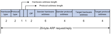
· Hardware type—Hardware address type. The value 1 represents Ethernet.
· Protocol type—Type of the protocol address to be mapped. The hexadecimal value 0x0800 represents IP.
· Hardware address length and protocol address length—Length, in bytes, of a hardware address and a protocol address. For an Ethernet address, the value of the hardware address length field is 6. For an IPv4 address, the value of the protocol address length field is 4.
· OP—Operation code, which describes the type of ARP message. The value 1 represents an ARP request, and the value 2 represents an ARP reply.
· Sender hardware address—Hardware address of the device sending the message.
· Sender protocol address—Protocol address of the device sending the message.
· Target hardware address—Hardware address of the device to which the message is being sent.
· Target protocol address—Protocol address of the device to which the message is being sent.
ARP operating mechanism
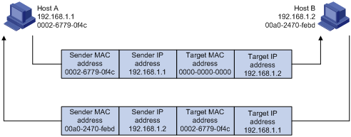
As shown in Figure 2, Host A and Host B are on the same subnet. Host A sends a packet to Host B as follows:
1. Host A looks through the ARP table for an ARP entry for Host B. If one entry is found, Host A uses the MAC address in the entry to encapsulate the IP packet into a data link layer frame. Then Host A sends the frame to Host B.
2. If Host A finds no entry for Host B, Host A buffers the packet and broadcasts an ARP request. The payload of the ARP request contains the following information:
? Sender IP address and sender MAC address—Host A's IP address and MAC address.
? Target IP address—Host B's IP address.
? Target MAC address—An all-zero MAC address.
All hosts on this subnet can receive the broadcast request, but only the requested host (Host B) processes the request.
3. Host B compares its own IP address with the target IP address in the ARP request. If they are the same, Host B operates as follows:
a. Adds the sender IP address and sender MAC address into its ARP table.
b. Encapsulates its MAC address into an ARP reply.
c. Unicasts the ARP reply to Host A.
4. After receiving the ARP reply, Host A operates as follows:
a. Adds the MAC address of Host B into its ARP table.
b. Encapsulates the MAC address into the packet and sends the packet to Host B.
Figure 2 ARP address resolution process
If Host A and Host B are on different subnets, Host A sends a packet to Host B as follows:
1. Host A broadcasts an ARP request where the target IP address is the IP address of the gateway.
2. The gateway responds with its MAC address in an ARP reply to Host A.
3. Host A uses the gateway's MAC address to encapsulate the packet, and then sends the packet to the gateway.
4. If the gateway has an ARP entry for Host B, it forwards the packet to Host B directly. If not, the gateway broadcasts an ARP request, in which the target IP address is the IP address of Host B.
5. After the gateway gets the MAC address of Host B, it sends the packet to Host B.
ARP table
An ARP table stores dynamic and static ARP entries.
Dynamic ARP entry
ARP automatically creates and updates dynamic entries. A dynamic ARP entry is removed when its aging timer expires or the output interface goes down. In addition, a dynamic ARP entry can be overwritten by a static ARP entry.
Static ARP entry
A static ARP entry is manually configured and maintained. It does not age out and cannot be overwritten by any dynamic ARP entry.
Static ARP entries protect communication between devices because attack packets cannot modify the IP-to-MAC mapping in a static ARP entry.
The device supports the following types of static ARP entries:
· Long static ARP entry—It contains the IP address, MAC address, VLAN, and output interface.
A long static ARP entry is directly used for forwarding packets.
· Short static ARP entry—It contains only the IP address and MAC address.
? If the output interface is a Layer 3 Ethernet interface, the short ARP entry can be directly used to forward packets.
? If the output interface is a VLAN interface, the device sends an ARP request whose target IP address is the IP address in the short entry. If the sender IP and MAC addresses in the received ARP reply match the short static ARP entry, the device performs the following operations:
- Adds the interface that received the ARP reply to the short static ARP entry.
- Uses the resolved short static ARP entry to forward IP packets.
To communicate with a host by using a fixed IP-to-MAC mapping, configure a short static ARP entry on the device. To communicate with a host by using a fixed IP-to-MAC mapping through an interface in a VLAN, configure a long static ARP entry on the device.
Command and hardware compatibility
The WX1800H series access controllers do not support the slot keyword or the slot-number argument.
Configuring a static ARP entry
A static ARP entry is effective when the device functions correctly. If a VLAN or VLAN interface is deleted, long static ARP entries in the VLAN are deleted, and resolved short static ARP entries in the VLAN become unresolved.
A resolved short static ARP entry becomes unresolved upon certain events. For example, it becomes unresolved when the resolved output interface goes down.
A long static ARP entry is ineffective in either of the following situations:
· The IP address in the entry conflicts with a local IP address.
· No local interface has an IP address in the same subnet as the IP address in the ARP entry.
To configure a static ARP entry:
|
Step |
Command |
Remarks |
|
1. Enter system view. |
system-view |
N/A |
|
2. Configure a static ARP entry. |
· Configure a long static ARP entry: · Configure a short static ARP entry: |
By default, no static ARP entry is configured. |
Setting the maximum number of dynamic ARP entries for a device
A device can dynamically learn ARP entries. To prevent a device from holding too many ARP entries, you can set the maximum number of dynamic ARP entries that the device can learn. When the maximum number is reached, the device stops learning ARP entries.
If you set a value lower than the number of existing dynamic ARP entries, the device does not remove the existing entries unless they are aged out.
To set the maximum number of dynamic ARP entries for a device:
|
Step |
Command |
Remarks |
|
1. Enter system view. |
system-view |
N/A |
|
2. Set the maximum number of dynamic ARP entries for the device. |
arp max-learning-number number slot slot-number |
By default, the maximum number of dynamic ARP entries varies by device model. For more information, see Layer 3—IP Services Command Reference. To disable the device from learning dynamic ARP entries, set the number to 0. |
Setting the maximum number of dynamic ARP entries for an interface
An interface can dynamically learn ARP entries. To prevent an interface from holding too many ARP entries, you can set the maximum number of dynamic ARP entries that the interface can learn. When the maximum number is reached, the interface stops learning ARP entries.
You can set limits for both a Layer 2 interface and the VLAN interface for a permitted VLAN on the Layer 2 interface. The Layer 2 interface learns an ARP entry only when neither limit is reached.
To set the maximum number of dynamic ARP entries for an interface:
|
Step |
Command |
Remarks |
|
1. Enter system view. |
system-view |
N/A |
|
2. Enter interface view. |
interface interface-type interface-number |
N/A |
|
3. Set the maximum number of dynamic ARP entries for the interface. |
arp max-learning-num number |
By default, the maximum number of dynamic ARP entries varies by device model. For more information, see Layer 3—IP Services Command Reference. To disable the interface from learning dynamic ARP entries, set the number to 0. |
Setting the aging timer for dynamic ARP entries
Each dynamic ARP entry in the ARP table has a limited lifetime, called an aging timer. The aging timer of a dynamic ARP entry is reset each time the dynamic ARP entry is updated. A dynamic ARP entry that is not updated before its aging timer expires is deleted from the ARP table.
To set the aging timer for dynamic ARP entries:
|
Step |
Command |
Remarks |
|
1. Enter system view. |
system-view |
N/A |
|
2. Set the aging timer for dynamic ARP entries. |
arp timer aging aging-time |
The default setting is 20 minutes. |
Enabling dynamic ARP entry check
The dynamic ARP entry check feature disables the device from supporting dynamic ARP entries that contain multicast MAC addresses. The device cannot learn dynamic ARP entries containing multicast MAC addresses. You cannot manually add static ARP entries containing multicast MAC addresses.
When dynamic ARP entry check is disabled, ARP entries containing multicast MAC addresses are supported. The device can learn dynamic ARP entries containing multicast MAC addresses obtained from the ARP packets sourced from a unicast MAC address. You can also manually add static ARP entries containing multicast MAC addresses.
To enable dynamic ARP entry check:
|
Step |
Command |
Remarks |
|
1. Enter system view. |
system-view |
N/A |
|
2. Enable dynamic ARP entry check. |
arp check enable |
By default, dynamic ARP entry check is enabled. |
Enabling ARP logging
This feature enables a device to log ARP events when ARP cannot resolve IP addresses correctly. The device can log the following ARP events:
· On a proxy ARP-disabled interface, the target IP address of a received ARP packet is not one of the following IP addresses:
? The IP address of the receiving interface.
? The public IP address after NAT.
· The sender IP address of a received ARP reply conflicts with one of the following IP addresses:
? The IP address of the receiving interface.
? The public IP address after NAT.
The device sends ARP log messages to the information center. You can use the info-center source command to specify the log output rules for the information center. For more information about information center, see Network Management and Monitoring Configuration Guide.
To enable the ARP logging feature:
|
Step |
Command |
Remarks |
|
1. Enter system view. |
system-view |
N/A |
|
2. Enable the ARP logging feature. |
arp check log enable |
By default, ARP logging is disabled. |
Displaying and maintaining ARP
|
|
IMPORTANT: Clearing ARP entries from the ARP table might cause communication failures. Make sure the entries to be cleared do not affect current communications. |
Execute display commands in any view and reset commands in user view.
|
Task |
Command |
|
Display ARP entries. |
display arp [ [ all | dynamic | static ] [ slot slot-number ] | vlan vlan-id | interface interface-type interface-number ] [ count | verbose ] |
|
Display the ARP entry for an IP address. |
display arp ip-address [ slot slot-number ] [ verbose ] |
|
Display the aging timer of dynamic ARP entries. |
display arp timer aging |
|
Clear ARP entries from the ARP table. |
reset arp { all | dynamic | interface interface-type interface-number | slot slot-number | static } |
Configuring gratuitous ARP
Overview
In a gratuitous ARP packet, the sender IP address and the target IP address are the IP address of the sending device.
A device sends a gratuitous ARP packet for either of the following purposes:
· Determine whether its IP address is already used by another device. If the IP address is already used, the device is informed of the conflict by an ARP reply.
· Inform other devices of a MAC address change.
Gratuitous ARP packet learning
This feature enables a device to create or update ARP entries by using the sender IP and MAC addresses in received gratuitous ARP packets.
When this feature is disabled, the device uses received gratuitous ARP packets to update existing ARP entries only. ARP entries are not created based on the received gratuitous ARP packets, which saves ARP table space.
Periodic sending of gratuitous ARP packets
Enabling periodic sending of gratuitous ARP packets helps downstream devices update ARP entries or MAC entries in a timely manner.
This feature can implement the following functions:
· Prevent gateway spoofing.
Gateway spoofing occurs when an attacker uses the gateway address to send gratuitous ARP packets to the hosts on a network. The traffic destined for the gateway from the hosts is sent to the attacker instead. As a result, the hosts cannot access the external network.
To prevent such gateway spoofing attacks, you can enable the gateway to send gratuitous ARP packets at intervals. Gratuitous ARP packets contain the primary IP address and manually configured secondary IP addresses of the gateway, so hosts can learn correct gateway information.
· Prevent ARP entries from aging out.
If network traffic is heavy or if the host CPU usage is high, received ARP packets can be discarded or are not promptly processed. Eventually, the dynamic ARP entries on the receiving host age out. The traffic between the host and the corresponding devices is interrupted until the host re-creates the ARP entries.
To prevent this problem, you can enable the gateway to send gratuitous ARP packets periodically. Gratuitous ARP packets contain the primary IP address and manually configured secondary IP addresses of the gateway, so the receiving hosts can update ARP entries in a timely manner.
Configuration procedure
When you configure gratuitous ARP, follow these restrictions and guidelines:
· You can enable periodic sending of gratuitous ARP packets on a maximum of 1024 interfaces.
· Periodic sending of gratuitous ARP packets takes effect on an interface only when the following conditions are met:
? The data link layer state of the interface is up.
? The interface has an IP address.
· If you change the sending interval for gratuitous ARP packets, the configuration takes effect at the next sending interval.
· The sending interval for gratuitous ARP packets might be much longer than the specified sending interval in any of the following circumstances:
? This feature is enabled on multiple interfaces.
? Each interface is configured with multiple secondary IP addresses.
? A small sending interval is configured when the previous two conditions exist.
To configure gratuitous ARP:
|
Step |
Command |
Remarks |
|
1. Enter system view. |
system-view |
N/A |
|
2. Enable learning of gratuitous ARP packets. |
gratuitous-arp-learning enable |
By default, learning of gratuitous ARP packets is enabled. |
|
3. Enable the device to send gratuitous ARP packets upon receiving ARP requests whose sender IP address belongs to a different subnet. |
gratuitous-arp-sending enable |
By default, a device does not send gratuitous ARP packets upon receiving ARP requests whose sender IP address belongs to a different subnet. |
|
4. Enter interface view. |
interface interface-type interface-number |
N/A |
|
5. Enable periodic sending of gratuitous ARP packets. |
arp send-gratuitous-arp [ interval milliseconds ] |
By default, periodic sending of gratuitous ARP packets is disabled. |
Enabling IP conflict notification
By default, if the sender IP address of an ARP packet is being used by the receiving device, the receiving device sends a gratuitous ARP request. It also displays an error message after it receives an ARP reply about the conflict.
You can use this command to enable the device to display error messages before sending a gratuitous ARP reply or request for conflict confirmation.
To enable IP conflict notification:
|
Step |
Command |
Remarks |
|
1. Enter system view. |
system-view |
N/A |
|
2. Enable IP conflict notification. |
arp ip-conflict log prompt |
By default, IP conflict notification is disabled. |
Configuring proxy ARP
Proxy ARP enables a device on one network to answer ARP requests for an IP address on another network. With proxy ARP, hosts on different broadcast domains can communicate with each other as they would on the same broadcast domain.
Proxy ARP includes common proxy ARP and local proxy ARP.
· Common proxy ARP—Allows communication between hosts that connect to different Layer 3 interfaces and reside in different broadcast domains.
· Local proxy ARP—Allows communication between hosts that connect to the same Layer 3 interface and reside in different broadcast domains.
Enabling common proxy ARP
|
Step |
Command |
Remarks |
|
1. Enter system view. |
system-view |
N/A |
|
2. Enter interface view. |
interface interface-type interface-number |
The following interface types are supported: · VLAN interface. · Layer 3 Ethernet interface. · Layer 3 Ethernet subinterface. |
|
3. Enable common proxy ARP. |
proxy-arp enable |
By default, common proxy ARP is disabled. |
Enabling local proxy ARP
|
Step |
Command |
Remarks |
|
1. Enter system view. |
system-view |
N/A |
|
2. Enter interface view. |
interface interface-type interface-number |
The following interface types are supported: · VLAN interface. · Layer 3 Ethernet interface. · Layer 3 Ethernet subinterface. |
|
3. Enable local proxy ARP. |
local-proxy-arp enable [ ip-range startIP to endIP ] |
By default, local proxy ARP is disabled. |
Displaying proxy ARP
Execute display commands in any view.
|
Task |
Command |
|
Display common proxy ARP status. |
display proxy-arp [ interface interface-type interface-number ] |
|
Display local proxy ARP status. |
display local-proxy-arp [ interface interface-type interface-number ] |
Common proxy ARP configuration example
Network requirements
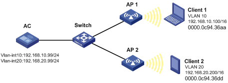
As shown in Figure 3, Client 1 and Client 2 have the same IP prefix and mask, but they are located on different subnets separated by the switch. Client 1 belongs to VLAN 10, and Client 2 belongs to VLAN 20. No default gateway is configured on Client 1 and Client 2.
Configure common proxy ARP on the AC to enable communication between the two clients.
Configuration procedure
# Create VLAN 10 and VLAN 20.
<AC> system-view
[AC] vlan 10
[AC-vlan10] quit
[AC] vlan 20
[AC-vlan20] quit
# Configure the IP address of VLAN-interface 10.
[AC] interface vlan-interface 10
[AC-Vlan-interface10] ip address 192.168.10.99 255.255.255.0
# Enable common proxy ARP on VLAN-interface 10.
[AC-Vlan-interface10] proxy-arp enable
[AC-Vlan-interface10] quit
# Configure the IP address of VLAN-interface 20.
[AC] interface vlan-interface 20
[AC-Vlan-interface20] ip address 192.168.20.99 255.255.255.0
# Enable common proxy ARP on VLAN-interface 20.
[AC-Vlan-interface20] proxy-arp enable
Verifying the configuration
# Verify that Client 1 and Client 2 can ping each other.
Configuring ARP fast-reply
Overview
ARP fast-reply enables a device to directly answer ARP requests according to DHCP snooping entries. ARP fast-reply functions in a VLAN. For information about DHCP snooping, see "Configuring DHCP snooping."
If the target IP address of a received ARP request is the IP address of the VLAN interface, the device delivers the request to the ARP module. If not, the device takes the following steps to process the packet:
1. Search the DHCP snooping table for a match by using the target IP address.
2. If a match is found, whether the device returns a reply depends on the type of interface in the matching entry.
? If the interface is the Ethernet interface that received the ARP request, the device does not return any reply.
? If the interface is a wireless interface or an Ethernet interface other than the receiving interface, the device returns a reply according to the matching entry.
3. If no matching DHCP snooping entry is found, the ARP request is forwarded to other interfaces except the receiving interface in the VLAN, or delivered to other modules.
Configuration procedure
|
Step |
Command |
Remarks |
|
1. Enter system view. |
system-view |
N/A |
|
2. Enter VLAN view. |
vlan vlan-id |
N/A |
|
3. Enable ARP fast-reply. |
arp fast-reply enable |
By default, ARP fast-reply is disabled. |
ARP fast-reply configuration example
Network requirements
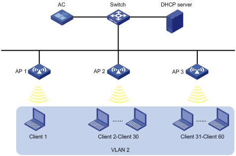
As shown in Figure 4, all clients are in VLAN 2, and access the network through the switch. APs are connected to VLAN 2. They have obtained IP addresses through DHCP.
Enable ARP fast-reply for VLAN 2. The AC directly returns an ARP reply without broadcasting received ARP requests to other APs upon receiving an ARP request from a client.
Configuration procedure
1. Configure basic functions on the AC. For more information about the configuration, see WLAN Configuration Guide.
2. Enable ARP fast-reply for VLAN 2 on the AC.
[AC] vlan 2
[AC-vlan2] arp fast-reply enable
[AC-vlan2] quit
Configuring IP addressing
The IP addresses in this chapter refer to IPv4 addresses unless otherwise specified.
This chapter describes IP addressing basics and manual IP address assignment for interfaces. Dynamic IP address assignment (BOOTP and DHCP) and PPP address negotiation are beyond the scope of this chapter.
Overview
This section describes the IP addressing basics.
IP addressing uses a 32-bit address to identify each host on an IPv4 network. To make addresses easier to read, they are written in dotted decimal notation, each address being four octets in length. For example, address 00001010000000010000000100000001 in binary is written as 10.1.1.1.
IP address classes
Each IP address breaks down into the following sections:
· Net ID—Identifies a network. The first several bits of a net ID, known as the class field or class bits, identify the class of the IP address.
· Host ID—Identifies a host on a network.
IP addresses are divided into five classes, as shown in Figure 5. The shaded areas represent the address class. The first three classes are most commonly used.
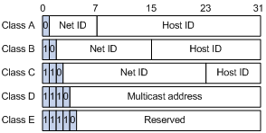
Table 1 IP address classes and ranges
|
Class |
Address range |
Remarks |
|
A |
0.0.0.0 to 127.255.255.255 |
The IP address 0.0.0.0 is used by a host at startup for temporary communication. This address is never a valid destination address. Addresses starting with 127 are reserved for loopback test. Packets destined to these addresses are processed locally as input packets rather than sent to the link. |
|
B |
128.0.0.0 to 191.255.255.255 |
N/A |
|
C |
192.0.0.0 to 223.255.255.255 |
N/A |
|
D |
224.0.0.0 to 239.255.255.255 |
Multicast addresses. |
|
E |
240.0.0.0 to 255.255.255.255 |
Reserved for future use, except for the broadcast address 255.255.255.255. |
Special IP addresses
The following IP addresses are for special use and cannot be used as host IP addresses:
· IP address with an all-zero net ID—Identifies a host on the local network. For example, IP address 0.0.0.16 indicates the host with a host ID of 16 on the local network.
· IP address with an all-zero host ID—Identifies a network.
· IP address with an all-one host ID—Identifies a directed broadcast address. For example, a packet with the destination address of 192.168.1.255 will be broadcast to all the hosts on the network 192.168.1.0.
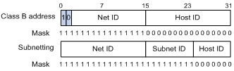
Subnetting and masking
Subnetting divides a network into smaller networks called subnets by using some bits of the host ID to create a subnet ID.
Masking identifies the boundary between the host ID and the combination of net ID and subnet ID.
Each subnet mask comprises 32 bits that correspond to the bits in an IP address. In a subnet mask, consecutive ones represent the net ID and subnet ID, and consecutive zeros represent the host ID.
Before being subnetted, Class A, B, and C networks use these default masks (also called natural masks): 255.0.0.0, 255.255.0.0, and 255.255.255.0, respectively.
Figure 6 Subnetting a Class B network
Subnetting increases the number of addresses that cannot be assigned to hosts. Therefore, using subnets means accommodating fewer hosts.
For example, a Class B network without subnetting can accommodate 1022 more hosts than the same network subnetted into 512 subnets.
· Without subnetting—65534 (216 – 2) hosts. (The two deducted addresses are the broadcast address, which has an all-one host ID, and the network address, which has an all-zero host ID.)
· With subnetting—Using the first nine bits of the host-id for subnetting provides 512 (29) subnets. However, only seven bits remain available for the host ID. This allows 126 (27 – 2) hosts in each subnet, a total of 64512 (512 × 126) hosts.
Assigning an IP address to an interface
An interface must have an IP address to communicate with other hosts. You can either manually assign an IP address to an interface, or configure the interface to obtain an IP address through BOOTP, DHCP, or PPP address negotiation. If you change the IP address assignment method, the new IP address will overwrite the previous address.
An interface can have one primary address and multiple secondary addresses.
Typically, you need to configure a primary IP address for an interface. If the interface connects to multiple subnets, configure primary and secondary IP addresses on the interface so the subnets can communicate with each other through the interface.
Configuration guidelines
Follow these guidelines when you assign an IP address to an interface:
· An interface can have only one primary IP address. A newly configured primary IP address overwrites the previous one.
· You cannot assign secondary IP addresses to an interface that obtains an IP address through BOOTP, DHCP, or PPP address negotiation.
· The primary and secondary IP addresses assigned to the interface can be located on the same network segment. Different interfaces on your device must reside on different network segments.
Configuration procedure
To assign an IP address to an interface:
|
Step |
Command |
Remarks |
|
1. Enter system view. |
system-view |
N/A |
|
2. Enter interface view. |
interface interface-type interface-number |
N/A |
|
3. Assign an IP address to the interface. |
ip address ip-address { mask | mask-length } [ sub ] |
By default, no IP address is assigned to the interface. |
Displaying and maintaining IP addressing
Execute display commands in any view.
|
Task |
Command |
|
Display IP configuration and statistics for the specified or all Layer 3 interfaces. |
display ip interface [ interface-type interface-number ] |
|
Display brief IP configuration for Layer 3 interfaces. |
display ip interface [ interface-type [ interface-number ] ] brief [ description ] |
DHCP overview
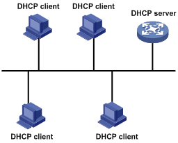
The Dynamic Host Configuration Protocol (DHCP) provides a framework to assign configuration information to network devices.
Figure 7 shows a typical DHCP application scenario where the DHCP clients and the DHCP server reside on the same subnet. The DHCP clients can also obtain configuration parameters from a DHCP server on another subnet through a DHCP relay agent. For more information about the DHCP relay agent, see "Configuring the DHCP relay agent."
Figure 7 A typical DHCP application
DHCP address allocation
Allocation mechanisms
DHCP supports the following allocation mechanisms:
· Static allocation—The network administrator assigns an IP address to a client, such as a WWW server, and DHCP conveys the assigned address to the client.
· Automatic allocation—DHCP assigns a permanent IP address to a client.
· Dynamic allocation—DHCP assigns an IP address to a client for a limited period of time, which is called a lease. Most DHCP clients obtain their addresses in this way.
IP address allocation process
Figure 8 IP address allocation process
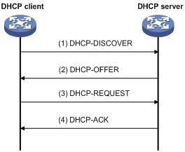
As shown in Figure 8, a DHCP server assigns an IP address to a DHCP client in the following process:
1. The client broadcasts a DHCP-DISCOVER message to locate a DHCP server.
2. Each DHCP server offers configuration parameters such as an IP address to the client in a DHCP-OFFER message. The sending mode of the DHCP-OFFER is determined by the flag field in the DHCP-DISCOVER message. For more information, see "DHCP message format."
3. If the client receives multiple offers, it accepts the first received offer, and broadcasts it in a DHCP-REQUEST message to formally request the IP address. (IP addresses offered by other DHCP servers can be assigned to other clients.)
4. All DHCP servers receive the DHCP-REQUEST message. However, only the server selected by the client does one of the following operations:
? Returns a DHCP-ACK message to confirm that the IP address has been allocated to the client.
? Returns a DHCP-NAK message to deny the IP address allocation.
After receiving the DHCP-ACK message, the client verifies the following details before using the assigned IP address:
· The assigned IP address is not in use. To verify this, the client broadcasts a gratuitous ARP packet. The assigned IP address is not in use if no response is received within the specified time.
· The assigned IP address is not on the same subnet as any IP address in use on the client.
Otherwise, the client sends a DHCP-DECLINE message to the server to request an IP address again.
IP address lease extension
A dynamically assigned IP address has a lease. When the lease expires, the IP address is reclaimed by the DHCP server. To continue using the IP address, the client must extend the lease duration.
When about half of the lease duration elapses, the DHCP client unicasts a DHCP-REQUEST to the DHCP server to extend the lease. Depending on the availability of the IP address, the DHCP server returns one of the following messages:
· A DHCP-ACK unicast confirming that the client's lease duration has been extended.
· A DHCP-NAK unicast denying the request.
If the client receives no reply, it broadcasts another DHCP-REQUEST message for lease extension when about seven-eighths of the lease duration elapses. Again, depending on the availability of the IP address, the DHCP server returns either a DHCP-ACK unicast or a DHCP-NAK unicast.
DHCP message format
Figure 9 shows the DHCP message format. DHCP uses some of the fields in significantly different ways. The numbers in parentheses indicate the size of each field in bytes.
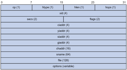
· op—Message type defined in options field. 1 = REQUEST, 2 = REPLY
· htype, hlen—Hardware address type and length of the DHCP client.
· hops—Number of relay agents a request message traveled.
· xid—Transaction ID, a random number chosen by the client to identify an IP address allocation.
· secs—Filled in by the client, the number of seconds elapsed since the client began address acquisition or renewal process. This field is reserved and set to 0.
· flags—The leftmost bit is defined as the BROADCAST (B) flag. If this flag is set to 0, the DHCP server sent a reply back by unicast. If this flag is set to 1, the DHCP server sent a reply back by broadcast. The remaining bits of the flags field are reserved for future use.
· ciaddr—Client IP address if the client has an IP address that is valid and usable. Otherwise, set to zero. (The client does not use this field to request an IP address to lease.)
· yiaddr—Your IP address. It is an IP address assigned by the DHCP server to the DHCP client.
· siaddr—Server IP address, from which the client obtained configuration parameters.
· giaddr—Gateway IP address. It is the IP address of the first relay agent to which a request message travels.
· chaddr—Client hardware address.
· sname—Server host name, from which the client obtained configuration parameters.
· file—Boot file (also called system software image) name and path information, defined by the server to the client.
· options—Optional parameters field that is variable in length. Optional parameters include the message type, lease duration, subnet mask, domain name server IP address, and WINS IP address.
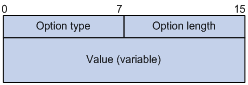
DHCP options
DHCP extends the message format as an extension to BOOTP for compatibility. DHCP uses the options field to carry information for dynamic address allocation and provide additional configuration information for clients.
Figure 10 DHCP option format
DHCP server's DHCP options
The following are DHCP server's DHCP options:
· Option 3—Router option. It specifies the gateway address.
· Option 6—DNS server option. It specifies the DNS server's IP address.
· Option 33—Static route option. It specifies a list of classful static routes (the destination addresses in these static routes are classful) that a client should add into its routing table. If both Option 33 and Option 121 exist, Option 33 is ignored.
· Option 51—IP address lease option.
· Option 53—DHCP message type option. It identifies the type of the DHCP message.
· Option 55—Parameter request list option. It is used by a DHCP client to request specified configuration parameters. The option includes values that correspond to the parameters requested by the client.
· Option 60—Vendor class identifier option. A DHCP client uses this option to identify its vendor. A DHCP server uses this option to distinguish DHCP clients, and assigns IP addresses to them.
· Option 66—TFTP server name option. It specifies a TFTP server to be assigned to the client.
· Option 67—Boot file name option. It specifies the boot file name to be assigned to the client.
· Option 121—Classless route option. It specifies a list of classless static routes (the destination addresses in these static routes are classless) that a client should add into its routing table. If both Option 33 and Option 121 exist, Option 33 is ignored.
· Option 150—TFTP server IP address option. It specifies the TFTP server IP address to be assigned to the client.
For more information about DHCP options, see RFC 2132 and RFC 3442.
Custom DHCP options
Some options, such as Option 43, Option 82, and Option 184, have no standard definitions in RFC 2132.
Vendor-specific option (Option 43)
DHCP servers and clients use Option 43 to exchange vendor-specific configuration information.
The DHCP client can obtain the following information through Option 43:
· ACS parameters, including the ACS URL, username, and password.
· Service provider identifier, which is acquired by the CPE from the DHCP server and sent to the ACS for selecting vender-specific configurations and parameters.
· PXE server address, which is used to obtain the boot file or other control information from the PXE server.
· AC address, which is used by an AP to obtain the boot file or other control information from the AC.
1. Format of Option 43:
Figure 11 Option 43 format
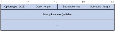
Network configuration parameters are carried in different sub-options of Option 43 as shown in Figure 11.
? Sub-option type—The field value can be 0x01 (ACS parameter sub-option), 0x02 (service provider identifier sub-option), or 0x80 (PXE server address sub-option).
? Sub-option length—Excludes the sub-option type and sub-option length fields.
? Sub-option value—The value format varies by sub-option.
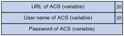
2. Sub-option value field formats:
? ACS parameter sub-option value field—Includes the ACS URL, username, and password separated by spaces (0x20) as shown in Figure 12.
Figure 12 ACS parameter sub-option value field
? Service provider identifier sub-option value field—Includes the service provider identifier.
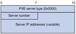
? PXE server address sub-option value field—Includes the PXE server type that can only be 0, the server number that indicates the number of PXE servers contained in the sub-option, and server IP addresses, as shown in Figure 13.
Figure 13 PXE server address sub-option value field
Relay agent option (Option 82)
Option 82 is the relay agent option. It records the location information about the DHCP client. When a DHCP relay agent receives a client's request, it adds Option 82 to the request and sends it to the server.
The administrator can use Option 82 to locate the DHCP client and further implement security control and accounting. The DHCP server can use Option 82 to provide individual configuration policies for the clients.
Option 82 can include a maximum of 255 sub-options and must include a minimum of one sub-option. Option 82 supports two sub-options: sub-option 1 (Circuit ID) and sub-option 2 (Remote ID). Option 82 has no standard definition. Its padding formats vary by vendor.
· Circuit ID has the following padding modes:
? String padding mode—Includes a character string specified by the user.
? Normal padding mode—Includes the VLAN ID and interface number of the interface that receives the client's request.
? Verbose padding mode—Includes the access node identifier specified by the user, and the VLAN ID, interface number and interface type of the interface that receives the client's request.
· Remote ID has the following padding modes:
? String padding mode—Includes a character string specified by the user.
? Normal padding mode—Includes the MAC address of the DHCP relay agent interface that receives the client's request.
? Sysname padding mode—Includes the device name of the device. To set the device name for the device, use the sysname command in system view.
Option 184
Option 184 is a reserved option. You can define the parameters in the option as needed. The device supports Option 184 carrying voice related parameters, so a DHCP client with voice functions can get voice parameters from the DHCP server.
Option 184 has the following sub-options:
· Sub-option 1—Specifies the IP address of the primary network calling processor. The primary processor acts as the network calling control source and provides program download services. For Option 184, you must define sub-option 1 to make other sub-options take effect.
· Sub-option 2—Specifies the IP address of the backup network calling processor. DHCP clients contact the backup processor when the primary one is unreachable.
· Sub-option 3—Specifies the voice VLAN ID and the result whether the DHCP client takes this VLAN as the voice VLAN.
· Sub-option 4—Specifies the failover route that includes the IP address and the number of the target user. A SIP VoIP user uses this IP address and number to directly establish a connection to the target SIP user when both the primary and backup calling processors are unreachable.
Protocols and standards
· RFC 2131, Dynamic Host Configuration Protocol
· RFC 2132, DHCP Options and BOOTP Vendor Extensions
· RFC 1542, Clarifications and Extensions for the Bootstrap Protocol
· RFC 3046, DHCP Relay Agent Information Option
· RFC 3442, The Classless Static Route Option for Dynamic Host Configuration Protocol (DHCP) version 4
Configuring the DHCP server
Overview
The DHCP server is well suited to networks where:
· Manual configuration and centralized management are difficult to implement.
· IP addresses are limited. For example, an ISP limits the number of concurrent online users, and users must acquire IP addresses dynamically.
· Most hosts do not need fixed IP addresses.
DHCP address pool
Each DHCP address pool has a group of assignable IP addresses and network configuration parameters. The DHCP server selects IP addresses and other parameters from the address pool and assigns them to the DHCP clients.
Address assignment mechanisms
Configure the following address assignment mechanisms as needed:
· Static address allocation—Manually bind the MAC address or ID of a client to an IP address in a DHCP address pool. When the client requests an IP address, the DHCP server assigns the IP address in the static binding to the client.
· Dynamic address allocation—Specify IP address ranges in a DHCP address pool. Upon receiving a DHCP request, the DHCP server dynamically selects an IP address from the matching IP address range in the address pool.
You can specify IP address ranges in an address pool by using either of the following methods:
· Method 1—Specify a primary subnet in an address pool and divide the subnet into multiple address ranges. These address ranges include a DHCP server's IP address range and IP address ranges for DHCP user classes.
Upon receiving a DHCP request, the DHCP server finds a user class matching the client and selects an IP address in the address range of the user class for the client. A user class can include multiple matching rules, and a client matches the user class as long as it matches any of the rules. In address pool view, you can specify different address ranges for different user classes.
The DHCP server selects an IP address for a client by performing the following steps:
a. DHCP server compares the client against DHCP user classes in the order they are configured.
b. If the client matches a user class, the DHCP server selects an IP address from the address range of the user class.
c. If the matching user class has no assignable addresses, the DHCP server compares the client against the next user class. If all the matching user classes have no assignable addresses, the DHCP server selects an IP address from the DHCP server's address range.
d. If the DHCP client does not match any DHCP user class, the DHCP server selects an address in the IP address range specified by the address range command. If the address range has no assignable IP addresses or it is not configured, the address allocation fails.
|
|
NOTE: All address ranges must belong to the primary subnet. If an address range does not reside on the primary subnet, DHCP cannot assign the addresses in the address range. |
· Method 2—Specify a primary subnet and multiple secondary subnets in an address pool.
The DHCP server selects an IP address from the primary subnet first. If there is no assignable IP address on the primary subnet, the DHCP server selects an IP address from secondary subnets in the order they are configured.
Principles for selecting an address pool
The DHCP server observes the following principles to select an address pool for a client:
1. If there is an address pool where an IP address is statically bound to the MAC address or ID of the client, the DHCP server selects this address pool and assigns the statically bound IP address and other configuration parameters to the client.
2. If the receiving interface has an address pool applied, the DHCP server selects an IP address and other configuration parameters from this address pool.
3. If no static address pool is configured and no address pool is applied to the receiving interface, the DHCP server selects an address pool depending on the client location.
? Client on the same subnet as the server—The DHCP server compares the IP address of the receiving interface with the primary subnets of all address pools.
- If a match is found, the server selects the address pool with the longest-matching primary subnet.
- If no match is found, the DHCP server compares the IP address with the secondary subnets of all address pools. The server selects the address pool with the longest-matching secondary subnet.
? Client on a different subnet than the server—The DHCP server compares the IP address in the giaddr field of the DHCP request with the primary subnets of all address pools.
- If a match is found, the server selects the address pool with the longest-matching primary subnet.
- If no match is found, the DHCP server compares the IP address with the secondary subnets of all address pools. The server selects the address pool with the longest-matching secondary subnet.
For example, two address pools 1.1.1.0/24 and 1.1.1.0/25 are configured but not applied to any DHCP server's interfaces.
· If the IP address of the receiving interface is 1.1.1.1/25, the DHCP server selects the address pool 1.1.1.0/25. If the address pool has no available IP addresses, the DHCP server will not select the other pool and the address allocation will fail.
· If the IP address of the receiving interface is 1.1.1.130/25, the DHCP server selects the address pool 1.1.1.0/24.
To ensure correct address allocation, keep the IP addresses used for dynamic allocation on one of the subnets:
· Clients on the same subnet as the server—Subnet where the DHCP server receiving interface resides.
· Clients on a different subnet than the server—Subnet where the first DHCP relay interface that faces the clients resides.
|
|
NOTE: H3C recommends that you configure a minimum of one matching primary subnet in your network. Otherwise, the DHCP server selects only the first matching secondary subnet for address allocation. If the network has more DHCP clients than the assignable IP addresses in the secondary subnet, not all DHCP clients can obtain IP addresses. |
IP address allocation sequence
The DHCP server selects an IP address for a client in the following sequence:
1. IP address statically bound to the client's MAC address or ID.
2. IP address that was ever assigned to the client.
3. IP address designated by the Option 50 field in the DHCP-DISCOVER message sent by the client.
Option 50 is the Requested IP Address option. The client uses this option to specify the wanted IP address in a DHCP-DISCOVER message. The content of Option 50 is user defined.
4. First assignable IP address found in the way discussed in "DHCP address pool."
5. IP address that was a conflict or passed its lease duration. If no IP address is assignable, the server does not respond.
DHCP server configuration task list
|
Tasks at a glance |
|
(Required.) Configuring an address pool on the DHCP server |
|
(Required.) Enabling DHCP |
|
(Required.) Enabling the DHCP server on an interface |
|
(Optional.) Applying an address pool on an interface |
|
(Optional.) Configuring a DHCP policy for dynamic address assignment |
|
(Optional.) Configuring IP address conflict detection |
|
(Optional.) Enabling handling of Option 82 |
|
(Optional.) Configuring DHCP server compatibility |
|
(Optional.) Setting the DSCP value for DHCP packets sent by the DHCP server |
|
(Optional.) Configuring DHCP binding auto backup |
|
(Optional.) Configuring address pool usage alarming |
|
(Optional.) Binding gateways to DHCP server's MAC address |
|
(Optional.) Advertising subnets assigned to clients |
|
(Optional.) Enabling client offline detection on the DHCP server |
|
(Optional.) Enabling DHCP logging on the DHCP server |
Configuring an address pool on the DHCP server
Configuration task list
Creating a DHCP address pool
|
Step |
Command |
Remarks |
|
1. Enter system view. |
system-view |
N/A |
|
2. Create a DHCP address pool and enter its view. |
dhcp server ip-pool pool-name |
By default, no DHCP address pool exists. |
Specifying IP address ranges for a DHCP address pool
You can configure both static and dynamic address allocation mechanisms in a DHCP address pool. For dynamic address allocation, you can specify either a primary subnet with multiple address ranges or a primary subnet with multiple secondary subnets for a DHCP address pool. You cannot configure both.
Specifying a primary subnet and multiple address ranges for a DHCP address pool
Some scenarios need to classify DHCP clients on the same subnet into different address groups. To meet this need, you can configure DHCP user classes and specify different address ranges for the classes. The clients matching a user class can then get the IP addresses of an address range. In addition, you can specify a DHCP server's address range for the clients that do not match any user class. If no DHCP server's address range is specified, such clients fail to obtain IP addresses.
If there is no need to classify clients, you do not need to configure DHCP user classes or their address ranges.
Follow these guidelines when you specify a primary subnet and multiple address ranges for a DHCP address pool:
· If you use the network or address range command multiple times for the same address pool, the most recent configuration takes effect.
· IP addresses specified by the forbidden-ip command are not assignable in the current address pool, but are assignable in other address pools. IP addresses specified by the dhcp server forbidden-ip command are not assignable in any address pool.
To specify a primary subnet and multiple address ranges for a DHCP address pool:
|
Step |
Command |
Remarks |
|
1. Enter system view. |
system-view |
N/A |
|
2. Create a DHCP user class and enter DHCP user class view. |
dhcp class class-name |
Required for client classification. By default, no DHCP user class exists. |
|
3. Configure a match rule for the DHCP user class. |
if-match rule rule-number { hardware-address hardware-address mask hardware-address-mask | option option-code [ ascii ascii-string [ offset offset | partial ] | hex hex-string [ mask mask | offset offset length length | partial ] ] | relay-agent gateway-address } |
Required for client classification. By default, no match rule is configured for a DHCP user class. |
|
4. Return to system view. |
quit |
N/A |
|
5. Create a DHCP address pool and enter its view. |
dhcp server ip-pool pool-name |
By default, no DHCP address pool exists. |
|
6. Specify the primary subnet for the address pool. |
network network-address [ mask-length | mask mask ] |
By default, no primary subnet is specified. |
|
7. (Optional.) Specify the DHCP server's address range. |
address range start-ip-address end-ip-address |
By default, no IP address range is specified. |
|
8. (Optional.) Specify an IP address range for a DHCP user class. |
class class-name range start-ip-address end-ip-address |
By default, no IP address range is specified for a user class. The DHCP user class must already exist. To specify address ranges for multiple DHCP user classes, repeat this step. |
|
9. (Optional.) Set the address lease duration. |
expired { day day [ hour hour [ minute minute [ second second ] ] ] | unlimited } |
The default setting is 1 day. |
|
10. (Optional.) Exclude the specified IP addresses in the address pool from dynamic allocation. |
forbidden-ip ip-address&<1-8> |
By default, all the IP addresses in the DHCP address pool are assignable. To exclude multiple address ranges from dynamic allocation, repeat this step. |
|
11. Return to system view. |
quit |
N/A |
|
12. (Optional.) Exclude the specified IP addresses from automatic allocation globally. |
dhcp server forbidden-ip start-ip-address [ end-ip-address ] |
By default, except for the IP address of the DHCP server interface, all IP addresses in address pools are assignable. To exclude multiple IP address ranges, repeat this step. |
Specifying a primary subnet and multiple secondary subnets for a DHCP address pool
If an address pool has a primary subnet and multiple secondary subnets, the server assigns IP addresses on a secondary subnet when the primary subnet has no assignable IP addresses.
Follow these guidelines when you specify a primary subnet and secondary subnets for a DHCP address pool:
· You can specify only one primary subnet in each address pool. If you use the network command multiple times, the most recent configuration takes effect.
· You can specify a maximum of 32 secondary subnets in each address pool.
· IP addresses specified by the forbidden-ip command are not assignable in the current address pool, but are assignable in other address pools. IP addresses specified by the dhcp server forbidden-ip command are not assignable in any address pool.
To specify a primary subnet and secondary subnets for a DHCP address pool:
|
Step |
Command |
Remarks |
|
1. Enter system view. |
system-view |
N/A |
|
2. Create a DHCP address pool and enter its view. |
dhcp server ip-pool pool-name |
By default, no DHCP address pool exists. |
|
3. Specify the primary subnet. |
network network-address [ mask-length | mask mask ] |
By default, no primary subnet is specified. |
|
4. (Optional.) Specify a secondary subnet. |
network network-address [ mask-length | mask mask ] secondary |
By default, no secondary subnet is specified. |
|
5. (Optional.) Return to address pool view. |
quit |
N/A |
|
6. (Optional.) Set the address lease duration. |
expired { day day [ hour hour [ minute minute [ second second ] ] ] | unlimited } |
The default setting is 1 day. |
|
7. (Optional.) Exclude the specified IP addresses from dynamic allocation. |
forbidden-ip ip-address&<1-8> |
By default, all the IP addresses in the DHCP address pool can be dynamically allocated. To exclude multiple address ranges from the address pool, repeat this step. |
|
8. Return to system view. |
quit |
N/A |
|
9. (Optional.) Exclude the specified IP addresses from dynamic allocation globally. |
dhcp server forbidden-ip start-ip-address [ end-ip-address ] |
Except for the IP address of the DHCP server interface, IP addresses in all address pools are assignable by default. To exclude multiple address ranges globally, repeat this step. |
Configuring a static binding in a DHCP address pool
Some DHCP clients, such as a WWW server, need fixed IP addresses. To provide a fixed IP address for a client, you can statically bind the MAC address or ID of the client to an IP address in a DHCP address pool. When the client requests an IP address, the DHCP server assigns the IP address in the static binding to the client.
Follow these guidelines when you configure a static binding:
· One IP address can be bound to only one client MAC or client ID. You cannot modify bindings that have been created. To change the binding for a DHCP client, you must delete the existing binding first.
· The IP address of a static binding cannot be the address of the DHCP server interface. Otherwise, an IP address conflict occurs and the bound client cannot obtain an IP address correctly.
· Multiple interfaces on the same device might all use DHCP to request a static IP address. In this case, use client IDs rather than the device's MAC address to identify the interfaces. Otherwise, IP address allocation will fail.
To configure a static binding:
|
Step |
Command |
Remarks |
|
1. Enter system view. |
system-view |
N/A |
|
2. Create a DHCP address pool and enter its view. |
dhcp server ip-pool pool-name |
By default, no DHCP address pool exists. |
|
3. Configure a static binding. |
static-bind ip-address ip-address [ mask-length | mask mask ] { client-identifier client-identifier | hardware-address hardware-address [ ethernet | token-ring ] } |
By default, no static binding is configured. To add more static bindings, repeat this step. |
|
4. (Optional.) Set the lease duration for the IP address. |
expired { day day [ hour hour [ minute minute [ second second ] ] ] | unlimited } |
The default setting is 1 day. |
Specifying gateways for DHCP clients
DHCP clients send packets destined for other networks to a gateway. The DHCP server can assign the gateway address to the DHCP clients.
You can specify gateway addresses in each address pool on the DHCP server. A maximum of 64 gateways can be specified in DHCP address pool view or secondary subnet view.
The DHCP server assigns gateway addresses to clients on a secondary subnet in the following ways:
· If gateways are specified in both address pool view and secondary subnet view, DHCP assigns those specified in the secondary subnet view.
· If gateways are specified in address pool view but not in secondary subnet view, DHCP assigns those specified in address pool view.
To configure gateways in the DHCP address pool:
|
Step |
Command |
Remarks |
|
1. Enter system view. |
system-view |
N/A |
|
2. Create a DHCP address pool and enter its view. |
dhcp server ip-pool pool-name |
By default, no DHCP address pool exists. |
|
3. Specify gateways. |
gateway-list ip-address&<1-64> |
By default, no gateway is specified. |
|
4. (Optional.) Enter secondary subnet view |
network network-address [ mask-length | mask mask ] secondary |
N/A |
|
5. (Optional.) Specify gateways. |
gateway-list ip-address&<1-64> |
By default, no gateway is specified. |
Specifying a domain name suffix for DHCP clients
You can specify a domain name suffix in a DHCP address pool on the DHCP server. With this suffix assigned, the client only needs to input part of a domain name, and the system adds the domain name suffix for name resolution. For more information about DNS, see "Configuring DNS."
To configure a domain name suffix in the DHCP address pool:
|
Step |
Command |
Remarks |
|
1. Enter system view. |
system-view |
N/A |
|
2. Create a DHCP address pool and enter its view. |
dhcp server ip-pool pool-name |
By default, no DHCP address pool exists. |
|
3. Specify a domain name suffix. |
domain-name domain-name |
By default, no domain name is specified. |
Specifying DNS servers for DHCP clients
To access hosts on the Internet through domain names, a DHCP client must contact a DNS server to resolve names. You can specify up to eight DNS servers in a DHCP address pool.
To specify DNS servers in a DHCP address pool:
|
Step |
Command |
Remarks |
|
1. Enter system view. |
system-view |
N/A |
|
2. Create a DHCP address pool and enter its view. |
dhcp server ip-pool pool-name |
By default, no DHCP address pool exists. |
|
3. Specify DNS servers. |
dns-list ip-address&<1-8> |
By default, no DNS server is specified. |
Specifying WINS servers and NetBIOS node type for DHCP clients
A Microsoft DHCP client using NetBIOS protocol must contact a WINS server for name resolution. You can specify up to eight WINS servers for such clients in a DHCP address pool.
In addition, you must specify a NetBIOS node type for the clients to approach name resolution. There are four NetBIOS node types:
· b (broadcast)-node—A b-node client sends the destination name in a broadcast message. The destination returns its IP address to the client after receiving the message.
· p (peer-to-peer)-node—A p-node client sends the destination name in a unicast message to the WINS server. The WINS server returns the destination IP address.
· m (mixed)-node—An m-node client broadcasts the destination name. If it receives no response, it unicasts the destination name to the WINS server to get the destination IP address.
· h (hybrid)-node—An h-node client unicasts the destination name to the WINS server. If it receives no response, it broadcasts the destination name to get the destination IP address.
To configure WINS servers and NetBIOS node type in a DHCP address pool:
|
Step |
Command |
Remarks |
|
1. Enter system view. |
system-view |
N/A |
|
2. Create a DHCP address pool and enter its view. |
dhcp server ip-pool pool-name |
By default, no DHCP address pool exists. |
|
3. Specify WINS servers. |
nbns-list ip-address&<1-8> |
This step is optional for b-node. By default, no WINS server is specified. |
|
4. Specify the NetBIOS node type. |
netbios-type { b-node | h-node | m-node | p-node } |
By default, no NetBIOS node type is specified. |
Specifying BIMS server for DHCP clients
Perform this task to provide the BIMS server IP address, port number, and shared key for the clients. The DHCP clients contact the BIMS server to get configuration files and perform software upgrade and backup.
To configure the BIMS server IP address, port number, and shared key in the DHCP address pool:
|
Step |
Command |
Remarks |
|
1. Enter system view. |
system-view |
N/A |
|
2. Create a DHCP address pool and enter its view. |
dhcp server ip-pool pool-name |
By default, no DHCP address pool exists. |
|
3. Specify the BIMS server IP address, port number, and shared key. |
bims-server ip ip-address [ port port-number ] sharekey { cipher | simple } key |
By default, no BIMS server information is specified. |
Specifying the configuration file for DHCP client auto-configuration
Auto-configuration enables a device to obtain a set of configuration settings automatically from servers when the device starts up without a configuration file. It requires the cooperation of the DHCP server, HTTP server, DNS server, and TFTP server. For more information about auto-configuration, see Fundamentals Configuration Guide.
The DHCP client uses the obtained parameters to contact the TFTP server or the HTTP server to get the configuration file.
To specify the configuration file name in a DHCP address pool:
|
Step |
Command |
Remarks |
|
1. Enter system view. |
system-view |
N/A |
|
2. Create a DHCP address pool and enter its view. |
dhcp server ip-pool pool-name |
By default, no DHCP address pool exists. |
|
3. Specify the IP address or the name of a TFTP server. |
· Specify the IP address of the TFTP server: · Specify the name of the TFTP server: |
You can specify both the IP address and name of the TFTP server. By default, no TFTP server is specified. |
|
4. Specify the configuration file name. |
bootfile-name bootfile-name |
By default, no configuration file name is specified. |
Specifying a server for DHCP clients
Some DHCP clients need to obtain configuration information from a server, such as a TFTP server. You can specify the IP address of that server. The DHCP server sends the server's IP address to DHCP clients along with other configuration information.
To specify the IP address of a server:
|
Step |
Command |
Remarks |
|
1. Enter system view. |
system-view |
N/A |
|
2. Create a DHCP address pool and enter its view. |
dhcp server ip-pool pool-name |
By default, no DHCP address pool exists. |
|
3. Specify the IP address of a server. |
next-server ip-address |
By default, no server is specified. |
Configuring Option 184 parameters for DHCP clients
To assign calling parameters to DHCP clients with voice service, you must configure Option 184 on the DHCP server. For more information about Option 184, see "Option 184."
To configure option 184 parameters in a DHCP address pool:
|
Step |
Command |
Remarks |
|
1. Enter system view. |
system-view |
N/A |
|
2. Create a DHCP address pool and enter its view. |
dhcp server ip-pool pool-name |
By default, no DHCP address pool exists. |
|
3. Specify the IP address of the primary network calling processor. |
voice-config ncp-ip ip-address |
By default, no primary network calling processor is specified. After you configure this command, the other Option 184 parameters take effect. |
|
4. (Optional.) Specify the IP address for the backup server. |
voice-config as-ip ip-address |
By default, no backup network calling processor is specified. |
|
5. (Optional.) Configure the voice VLAN. |
voice-config voice-vlan vlan-id { disable | enable } |
By default, no voice VLAN is configured. |
|
6. (Optional.) Specify the failover IP address and dialer string. |
voice-config fail-over ip-address dialer-string |
By default, no failover IP address or dialer string is specified. |
Customizing DHCP options
|
|
IMPORTANT: Use caution when customizing DHCP options because the configuration might affect DHCP operation. |
You can customize options for the following purposes:
· Add newly released options.
· Add options for which the vendor defines the contents, for example, Option 43.
· Add options for which the CLI does not provide a dedicated configuration command. For example, you can use the option 4 ip-address 1.1.1.1 command to define the time server address 1.1.1.1 for DHCP clients.
· Add all option values if the actual requirement exceeds the limit for a dedicated option configuration command. For example, the dns-list command can specify up to eight DNS servers. To specify more than eight DNS servers, you must use the option 6 command to define all DNS servers.
To customize a DHCP option in a DHCP address pool:
|
Step |
Command |
Remarks |
|
1. Enter system view. |
system-view |
N/A |
|
2. Create a DHCP address pool and enter its view. |
dhcp server ip-pool pool-name |
By default, no DHCP address pool exists. |
|
3. Customize a DHCP option. |
option code { ascii ascii-string | hex hex-string | ip-address ip-address&<1-8> } |
By default, no DHCP option is customized in a DHCP address pool. DHCP options specified in DHCP option groups take precedence over those specified in DHCP address pools. |
To customize a DHCP option in a DHCP option group:
|
Step |
Command |
Remarks |
|
1. Enter system view. |
system-view |
N/A |
|
2. Create a DHCP user class and enter DHCP user class view. |
dhcp class class-name |
By default, no DHCP user class exists. |
|
3. Configure a match rule for the DHCP user class. |
if-match rule rule-number { hardware-address hardware-address mask hardware-address-mask | option option-code [ ascii ascii-string [ offset offset | partial ] | hex hex-string [ mask mask | offset offset length length | partial ] ] | relay-agent gateway-address } |
By default, no match rule is configured for a DHCP user class. |
|
4. Return to system view. |
quit |
N/A |
|
5. Create a DHCP option group and enter DHCP option group view. |
dhcp option group option-group-number |
By default, no DHCP option group exists. |
|
6. Customize a DHCP option. |
option code { ascii ascii-string | hex hex-string | ip-address ip-address&<1-8> } |
By default, no DHCP option is customized in a DHCP option group. DHCP options specified in DHCP option groups take precedence over those specified in DHCP address pools. |
|
7. Create a DHCP address pool and enter DHCP address pool view. |
dhcp server ip-pool pool-name |
By default, no DHCP address pool exists. |
|
8. Specify the DHCP option group for the DHCP user class. |
class class-name option group option-group-number |
By default, no DHCP option group is specified for a DHCP user class. |
Table 2 DHCP server's DHCP options
|
Option |
Option name |
Corresponding command |
Recommended option command parameters |
|
3 |
Router Option |
gateway-list |
ip-address |
|
6 |
Domain Name Server Option |
dns-list |
ip-address |
|
15 |
Domain Name |
domain-name |
ascii |
|
44 |
NetBIOS over TCP/IP Name Server Option |
nbns-list |
ip-address |
|
46 |
NetBIOS over TCP/IP Node Type Option |
netbios-type |
hex |
|
66 |
TFTP server name |
tftp-server |
ascii |
|
67 |
Boot file name |
bootfile-name |
ascii |
|
43 |
Vendor Specific Information |
N/A |
hex |
Configuring the DHCP user class whitelist
The DHCP user class whitelist allows the DHCP server to process requests only from clients on the DHCP user class whitelist. The whitelist does not take effect on clients who request static IP addresses, and the server always processes their requests.
To configure the DHCP user class whitelist:
|
Step |
Command |
Remarks |
|
1. Enter system view. |
system-view |
N/A |
|
2. Create a DHCP user class and enter DHCP user class view. |
dhcp class class-name |
By default, no DHCP user class exists. |
|
3. Configure a match rule for the DHCP user class. |
if-match rule rule-number { hardware-address hardware-address mask hardware-address-mask | option option-code [ ascii ascii-string [ offset offset | partial ] | hex hex-string [ mask mask | offset offset length length | partial ] ] | relay-agent gateway-address } |
By default, no match rule is configured for a DHCP user class. |
|
4. Return to system view. |
quit |
N/A |
|
5. Create a DHCP address pool and enter DHCP address pool view. |
dhcp server ip-pool pool-name |
By default, no DHCP address pool exists. |
|
6. Enable the DHCP user class whitelist. |
verify class |
By default, the DHCP user class whitelist is disabled. |
|
7. Add DHCP user classes to the DHCP user class whitelist. |
valid class class-name&<1-8> |
By default, no DHCP user class is on the DHCP user class whitelist. |
Enabling DHCP
You must enable DHCP to validate other DHCP configurations.
To enable DHCP:
|
Step |
Command |
Remarks |
|
1. Enter system view. |
system-view |
N/A |
|
2. Enable DHCP. |
dhcp enable |
By default, DHCP is disabled. |
Enabling the DHCP server on an interface
Perform this task to enable the DHCP server on an interface. Upon receiving a DHCP request on the interface, the DHCP server assigns the client an IP address and other configuration parameters from a DHCP address pool.
To enable the DHCP server on an interface:
|
Step |
Command |
Remarks |
|
1. Enter system view. |
system-view |
N/A |
|
2. Enter interface view. |
interface interface-type interface-number |
N/A |
|
3. Enable the DHCP server on the interface. |
dhcp select server |
By default, the DHCP server on the interface is enabled. |
Applying an address pool on an interface
Perform this task to apply a DHCP address pool on an interface.
Upon receiving a DHCP request from the interface, the DHCP server performs address allocation in the following ways:
· If a static binding is found for the client, the server assigns the static IP address and configuration parameters from the address pool that contains the static binding.
· If no static binding is found for the client, the server uses the address pool applied to the interface for address and configuration parameter allocation.
To apply an address pool on an interface:
|
Step |
Command |
Remarks |
|
1. Enter system view. |
system-view |
N/A |
|
2. Enter interface view. |
interface interface-type interface-number |
N/A |
|
3. Apply an address pool on the interface. |
dhcp server apply ip-pool pool-name |
By default, no address pool is applied on an interface. If the applied address pool does not exist, the DHCP server fails to perform dynamic address allocation. |
Configuring a DHCP policy for dynamic address assignment
In a DHCP policy, each DHCP user class has a bound DHCP address pool. Clients matching different user classes obtain IP addresses and other parameters from different address pools. The DHCP policy must be applied to the interface that acts as the DHCP server. When receiving a DHCP request, the DHCP server compares the packet against the user classes in the order that they are configured.
· If a match is found and the bound address pool has assignable IP addresses, the server assigns an IP address and other parameters from the address pool. If the address pool does not have assignable IP addresses, the address assignment fails.
· If no match is found, the server assigns an IP address and other parameters from the default DHCP address pool. If no default address pool is specified or the default address pool does not have assignable IP addresses, the address assignment fails.
For successful address assignment, make sure the applied DHCP policy and the bound address pools exist.
To configure a DHCP policy for dynamic address assignment:
|
Step |
Command |
Remarks |
|
1. Enter system view. |
system-view |
N/A |
|
2. Create a DHCP user class and enter DHCP user class view. |
dhcp class class-name |
By default, no DHCP user class exists. |
|
3. Configure a match rule for the DHCP user class. |
if-match rule rule-number { hardware-address hardware-address mask hardware-address-mask | option option-code [ ascii ascii-string [ offset offset | partial ] | hex hex-string [ mask mask | offset offset length length | partial ] ] | relay-agent gateway-address } |
By default, no match rule is configured for a DHCP user class. |
|
4. Return to system view. |
quit |
N/A |
|
5. Create a DHCP policy and enter DHCP policy view. |
dhcp policy policy-name |
By default, no DHCP policy exists. |
|
6. Specify a DHCP address pool for a DHCP user class. |
class class-name ip-pool pool-name |
By default, no address pool is specified for a user class. |
|
7. Specify the default DHCP address pool. |
default ip-pool pool-name |
By default, no default address pool is specified. |
|
8. Return to system view. |
quit |
N/A |
|
9. Enter interface view. |
interface interface-type interface-number |
N/A |
|
10. Apply the DHCP policy to the interface. |
dhcp apply-policy policy-name |
By default, no DHCP policy is applied to an interface. |
Configuring IP address conflict detection
Before assigning an IP address, the DHCP server pings that IP address.
· If the server receives a response within the specified period, it selects and pings another IP address.
· If it receives no response, the server continues to ping the IP address until a specific number of ping packets are sent. If still no response is received, the server assigns the IP address to the requesting client. The DHCP client uses gratuitous ARP to perform IP address conflict detection.
To configure IP address conflict detection:
|
Step |
Command |
Remarks |
|
1. Enter system view. |
system-view |
N/A |
|
2. (Optional.) Set the maximum number of ping packets to be sent for conflict detection. |
dhcp server ping packets number |
The default setting is one. The value 0 disables IP address conflict detection. |
|
3. (Optional.) Set the ping timeout time. |
dhcp server ping timeout milliseconds |
The default setting is 500 ms. The value 0 disables IP address conflict detection. |
Enabling handling of Option 82
If you disable the DHCP to handle Option 82, it does not add Option 82 into the response message.
You must enable handling of Option 82 on both the DHCP server and the DHCP relay agent to ensure correct processing for Option 82. For information about enabling handling of Option 82 on the DHCP relay agent, see "Configuring Option 82."
To enable the DHCP server to handle Option 82:
|
Step |
Command |
Remarks |
|
1. Enter system view. |
system-view |
N/A |
|
2. Enable the server to handle Option 82. |
dhcp server relay information enable |
By default, handling of Option 82 is enabled. |
Configuring DHCP server compatibility
Perform this task to enable the DHCP server to support DHCP clients that are incompliant with RFC.
Configuring the DHCP server to broadcast all responses
By default, the DHCP server broadcasts a response only when the broadcast flag in the DHCP request is set to 1. You can configure the DHCP server to ignore the broadcast flag and always broadcast a response. This feature is useful when some clients set the broadcast flag to 0 but do not accept unicast responses.
The DHCP server always unicasts a response in the following situations, regardless of whether this feature is configured or not:
· The DHCP request is from a DHCP client that has an IP address (the ciaddr field is not 0).
· The DHCP request is forwarded by a DHCP relay agent from a DHCP client (the giaddr field is not 0).
To configure the DHCP server to broadcast all responses:
|
Step |
Command |
Remarks |
|
1. Enter system view. |
system-view |
N/A |
|
2. Enable the DHCP server to broadcast all responses. |
dhcp server always-broadcast |
By default, the DHCP server reads the broadcast flag to decide whether to broadcast or unicast a response. |
Configure the DHCP server to ignore BOOTP requests
The lease duration of the IP addresses obtained by the BOOTP clients is unlimited. For some scenarios that do not allow unlimited leases, you can configure the DHCP server to ignore BOOTP requests.
To configure the DHCP server to ignore BOOTP requests:
|
Step |
Command |
Remarks |
|
1. Enter system view. |
system-view |
N/A |
|
2. Configure the DHCP server to ignore BOOTP requests. |
dhcp server bootp ignore |
By default, the DHCP server processes BOOTP requests. |
Configuring the DHCP server to send BOOTP responses in RFC 1048 format
Not all BOOTP clients can send requests that are compatible with RFC 1048. By default, the DHCP server does not process the Vend field of RFC 1048-incompliant requests but copies the Vend field into responses.
This feature enables the DHCP server to fill the Vend field in RFC 1048-compliant format in DHCP responses to RFC 1048-incompliant requests sent by BOOTP clients.
This feature is effective for the BOOTP clients that request statically bound addresses.
To configure the DHCP server to send BOOTP responses in RFC 1048 format:
|
Step |
Command |
Remarks |
|
1. Enter system view. |
system-view |
N/A |
|
2. Enable the DHCP server to send BOOTP responses in RFC 1048 format to the RFC 1048-incompliant BOOTP requests for statically bound addresses. |
dhcp server bootp reply-rfc-1048 |
By default, the DHCP server directly copies the Vend field of such requests into the responses. |
Disabling Option 60 encapsulation in DHCP replies
If one or more DHCP clients cannot resolve Option 60, disable the DHCP server from encapsulating Option 60 in DHCP replies. If you do not disable the capability, the DHCP server encapsulates Option 60 in a DHCP reply in the following situations:
· The received DHCP packet contains Option 60.
· Option 60 is configured for the address pool.
To disable the DHCP server from encapsulating Option 60 in DHCP replies:
|
Step |
Command |
Remarks |
|
1. Enter system view. |
system-view |
N/A |
|
2. Disable the DHCP server from encapsulating Option 60 in DHCP replies. |
dhcp server reply-exclude-option60 |
By default, the DHCP server can encapsulate Option 60 in DHCP replies. |
Setting the DSCP value for DHCP packets sent by the DHCP server
The DSCP value of a packet specifies the priority level of the packet and affects the transmission priority of the packet.
To set the DSCP value for DHCP packets sent by the DHCP server:
|
Step |
Command |
Remarks |
|
1. Enter system view. |
system-view |
N/A |
|
2. Set the DSCP value for DHCP packets sent by the DHCP server. |
dhcp dscp dscp-value |
By default, the DSCP value in DHCP packets sent by the DHCP server is 56. |
Configuring DHCP binding auto backup
The auto backup feature saves bindings to a backup file and allows the DHCP server to download the bindings from the backup file at the server reboot. The bindings include the lease bindings and conflicted IP addresses. They cannot survive a reboot on the DHCP server.
The DHCP server does not provide services during the download process. If a connection error occurs during the process and cannot be repaired in a short amount of time, you can terminate the download operation. Manual interruption allows the DHCP server to provide services without waiting for the connection to be repaired.
To configure DHCP binding auto backup:
|
Step |
Command |
Remarks |
|
1. Enter system view. |
system-view |
N/A |
|
2. Configure the DHCP server to back up the bindings to a file. |
dhcp server database filename { filename | url url [ username username [ password { cipher | simple } key ] ] } |
By default, the DHCP server does not back up the DHCP bindings. With this command executed, the DHCP server backs up its bindings immediately and runs auto backup. |
|
3. (Optional.) Manually save the DHCP bindings to the backup file. |
dhcp server database update now |
N/A |
|
4. (Optional.) Set the waiting time after a DHCP binding change for the DHCP server to update the backup file. |
dhcp server database update interval seconds |
The default waiting time is 300 seconds. If no DHCP binding changes, the backup file is not updated. |
|
5. (Optional.) Terminate the download of DHCP bindings from the backup file. |
dhcp server database update stop |
N/A |
Configuring address pool usage alarming
Perform this task to set the threshold for address pool usage alarming. When the threshold is exceeded, the system sends log messages to the information center. According to the log information, you can optimize the address pool configuration. For more information about the information center, see Network Management and Monitoring Configuration Guide.
To configure address pool usage alarming:
|
Step |
Command |
Remarks |
|
1. Enter system view. |
system-view |
N/A |
|
2. Create a DHCP address pool and enter its view. |
dhcp server ip-pool pool-name |
By default, no DHCP address pool exists. |
|
3. Set the threshold for address pool usage alarming. |
ip-in-use threshold threshold-value |
The default threshold is 100%. |
Binding gateways to DHCP server's MAC address
As shown in Figure 14, the DHCP server is configured on the access device that provides access for clients of different service types, such as broadband, IPTV, and IP telephone. The clients of different types obtain IP addresses on different subnets. For the clients to access the network, the access interface typically has no IP address configured. You must bind the gateways to the server's MAC address when specifying gateways for the DHCP clients.
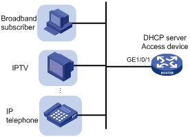
To bind the gateways to the DHCP server's MAC address:
|
Step |
Command |
Remarks |
|
1. Enter system view. |
system-view |
N/A |
|
2. Create a DHCP address pool and enter its view. |
dhcp server ip-pool pool-name |
By default, no DHCP address pool exists. |
|
3. Bind the gateways to the device's MAC address. |
gateway-list ip-address&<1-64> export-route |
By default, gateways are not bound to any MAC address. |
Advertising subnets assigned to clients
As shown in Figure 15, Router A and Router B act as both the DHCP server and the BRAS device. The BRAS devices send accounting packets to the RADIUS server. To enable the BRAS devices to collect correct accounting information for each RADIUS user, configure the DHCP server to advertise subnets assigned to clients. The upstream and downstream traffic of a RADIUS user will pass through the same BRAS device.
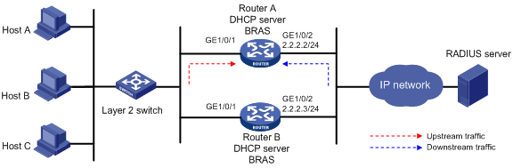
To configure the subnet advertisement feature:
|
Step |
Command |
Remarks |
|
1. Enter system view. |
system-view |
N/A |
|
2. Create a DHCP address pool and enter its view. |
dhcp server ip-pool pool-name |
By default, no DHCP address pool exists. |
|
3. Advertise subnets assigned to DHCP clients. |
network network-address [ mask-length | mask mask ] export-route [ secondary ] |
By default, the subnets assigned to DHCP clients are not advertised. |
Enabling client offline detection on the DHCP server
The client offline detection feature reclaims an assigned IP address and deletes the binding entry when the ARP entry for the IP address ages out. The feature does not function if an ARP entry is manually deleted.
To enable client offline detection on the DHCP server:
|
Step |
Command |
Remarks |
|
1. Enter system view. |
system-view |
N/A |
|
2. Enter interface view. |
interface interface-type interface-number |
N/A |
|
3. Enable client offline detection. |
dhcp client-detect |
By default, client offline detection is disabled on the DHCP server. |
Enabling DHCP logging on the DHCP server
The DHCP logging feature enables the DHCP server to generate DHCP logs and send them to the information center. For information about the log destination and output rule configuration in the information center, see Network Management and Monitoring Configuration Guide.
Disable this feature when the log generation affects the device performance or reduces the address allocation efficiency. For example, this situation might occur when a large number of clients frequently come online or go offline.
To enable DHCP logging on the DHCP server:
|
Step |
Command |
Remarks |
|
1. Enter system view. |
system-view |
N/A |
|
2. Enable DHCP logging. |
dhcp log enable |
By default, DHCP logging is disabled. |
Displaying and maintaining the DHCP server
|
|
IMPORTANT: A restart of the DHCP server or execution of the reset dhcp server ip-in-use command deletes all lease information. The DHCP server denies any DHCP request for lease extension, and the client must request an IP address again. |
Execute display commands in any view and reset commands in user view.
|
Task |
Command |
|
Display information about IP address conflicts. |
display dhcp server conflict [ ip ip-address ] |
|
Display information about DHCP binding auto backup. |
display dhcp server database |
|
Display information about lease-expired IP addresses. |
display dhcp server expired [ ip ip-address | pool pool-name ] |
|
Display information about assignable IP addresses. |
display dhcp server free-ip [ pool pool-name ] |
|
Display information about assigned IP addresses. |
display dhcp server ip-in-use [ ip ip-address | pool pool-name ] |
|
Display DHCP server statistics. |
display dhcp server statistics [ pool pool-name ] |
|
Display information about DHCP address pools. |
display dhcp server pool [ pool-name ] |
|
Clear information about IP address conflicts. |
reset dhcp server conflict [ ip ip-address ] |
|
Clear information about lease-expired IP addresses. |
reset dhcp server expired [ ip ip-address | pool pool-name ] |
|
Clear information about assigned IP addresses. |
reset dhcp server ip-in-use [ ip ip-address | pool pool-name ] |
|
Clear DHCP server statistics. |
reset dhcp server statistics |
DHCP server configuration examples
DHCP networking includes the following types:
· The DHCP server and clients reside on the same subnet and exchange messages directly.
· The DHCP server and clients are not on the same subnet and they communicate with each other through a DHCP relay agent.
The DHCP server configuration for the two types is identical.
Dynamic IP address assignment configuration example
Network requirements
As shown in Figure 16, the DHCP server (AC) assigns IP addresses to the AP and DHCP clients on subnet 10.1.1.0/24, which is subnetted into 10.1.1.0/25 and 10.1.1.128/25.
Configure DHCP server on the AC to assign IP addresses on subnet 10.1.1.0/25 to the AP and IP addresses on subnet 10.1.1.128/25 to DHCP clients.
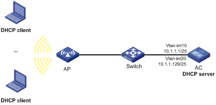
Configuration procedure
1. Configure VLANs and VLAN interfaces:
# Create VLAN 10 and VLAN 20.
<AC> system-view
[AC] vlan 10
[AC-vlan10] quit
[AC] vlan 20
[AC-vlan20] quit
# Add the interface connected to the AP to VLAN 10.
[AC] interface gigabitethernet 1/0/2
[AC-GigabitEthernet1/0/2] port link-type trunk
[AC-GigabitEthernet1/0/2] port trunk permit vlan 10
[AC-GigabitEthernet1/0/2] port trunk pvid vlan 10
[AC-GigabitEthernet1/0/2] quit
# Assign IP addresses to VLAN-interface 10 and VLAN-interface 20.
[AC] interface vlan-interface 10
[AC-Vlan-interface10] ip address 10.1.1.1 25
[AC-Vlan-interface10] quit
[AC] interface vlan-interface 20
[AC-Vlan-interface20] ip address 10.1.1.129 25
[AC-Vlan-interface20] quit
2. Configure wireless services:
# Configure a service template and bind VLAN 20 to the service template.
[AC] wlan service-template service
[AC-wlan-st-service] ssid service
[AC-wlan-st-service] vlan 20
[AC-wlan-st-service] service-template enable
[AC-wlan-st-service] quit
# Configure the AP.
[AC] wlan ap ap1 model WA536
[AC-wlan-ap-ap1] serial-id 219801A1NQB117012935
[AC-wlan-ap-ap1] radio 1
[AC-wlan-ap-ap1-radio-1] service-template service1
[AC-wlan-ap-ap1-radio-1] radio enable
[AC-wlan-ap-ap1-radio-1] return
3. Configure the DHCP server:
# Enable DHCP.
[AC] dhcp enable
# Enable the DHCP server on VLAN-interface 10 and VLAN-interface 20.
[AC] interface vlan-interface 10
[AC-Vlan-interface10] dhcp select server
[AC-Vlan-interface10] quit
[AC] interface vlan-interface 20
[AC-Vlan-interface20] dhcp select server
[AC-Vlan-interface20] quit
# Configure DHCP address pool 1 to assign IP addresses to the AP on subnet 10.1.1.0/25.
[AC] dhcp server ip-pool 1
[AC-dhcp-pool-1] network 10.1.1.0 mask 255.255.255.128
[AC-dhcp-pool-1] quit
# Configure DHCP address pool 2 to assign IP addresses to DHCP clients on subnet 10.1.1.128/25.
[AC] dhcp server ip-pool 2
[AC-dhcp-pool-2] network 10.1.1.128 mask 255.255.255.128
[AC-dhcp-pool-2] quit
Verifying the configuration
# Verify that the AP on subnet 10.1.1.0/25 and the DHCP clients on subnet 10.1.1.128/25 can obtain correct IP addresses from the DHCP server. (Details not shown.)
# On the DHCP server, display the IP addresses assigned to the AP and DHCP clients.
[AC] display dhcp server ip-in-use
IP address Client identifier/ Lease expiration Type
Hardware address
10.1.1.3 0031-3865-392e-6262- Jan 1 22:25:03 2015 Auto(C)
3363-2e30-3230-352d-
4745-302f-30
10.1.1.130 3030-3030-2e30-3030- Jan 9 10:45:11 2015 Auto(C)
662e-3030-3033-2d45-
7568-6572-1e
10.1.1.131 3030-0020-fe02-3020- Jan 9 10:45:11 2015 Auto(C)
7052-0201-2013-1e02
0201-9068-23
10.1.1.132 2020-1220-1102-3021- Jan 9 10:45:11 2015 Auto(C)
7e52-0211-2025-3402
0201-9068-9a
10.1.1.133 2021-d012-0202-4221- Jan 9 10:45:11 2015 Auto(C)
8852-0203-2022-55e0
3921-0104-31
DHCP user class configuration example
Network requirement
As shown in Figure 17, the DHCP relay agent (the switch) forwards DHCP packets between DHCP clients and the DHCP server (AC). Enable the switch to support Option 82 so that the switch can add Option 82 in the DHCP requests sent by the DHCP clients.
Configure the address allocation scheme as follows:
|
Assign IP addresses |
To clients |
|
10.10.1.2 to 10.10.1.10 |
The DHCP request contains Option 82. |
|
10.10.1.11 to 10.10.1.26 |
The hardware address in the request is six bytes long and begins with aabb-aabb-aab. |
For clients on subnet 10.10.1.0/24, the DNS server address is 10.10.1.20/24 and the gateway address is 10.10.1.254/24.
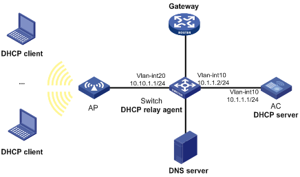
Configuration procedure
1. Assign IP addresses to interfaces on DHCP server and DHCP relay agent. (Details not shown.)
2. Configure basic settings on the AC. For more information, see WLAN Configuration Guide.
3. Configure DHCP services:
# Enable DHCP and configure the DHCP server to handle Option 82.
<AC> system-view
[AC] dhcp enable
[AC] dhcp server relay information enable
# Enable DHCP server on VLAN-interface10.
[AC] interface vlan-interface 10
[AC-Vlan-interface10] dhcp select server
[AC-Vlan-interface10] quit
# Create DHCP user class tt and configure a match rule to match client requests with Option 82.
[AC] dhcp class tt
[AC-dhcp-class-tt] if-match rule 1 option 82
[AC-dhcp-class-tt] quit
# Create DHCP user class ss and configure a match rule to match DHCP requests in which the hardware address is six bytes long and begins with aabb-aabb-aab.
[AC-dhcp-class-ss] if-match rule 1 hardware-address aabb-aabb-aab0 mask ffff-ffff-fff0
[AC-dhcp-class-ss] quit
# Create DHCP address pool aa.
[AC] dhcp server ip-pool aa
# Specify the subnet for dynamic allocation.
[AC-dhcp-pool-aa] network 10.10.1.0 mask 255.255.255.0
# Specify the address range for dynamic allocation.
[AC-dhcp-pool-aa] address range 10.10.1.2 10.10.1.100
# Specify the address range for user class tt.
[AC-dhcp-pool-aa] class tt range 10.10.1.2 10.10.1.10
# Specify the address range for user class ss.
[AC-dhcp-pool-aa] class ss range 10.10.1.11 10.10.1.26
# Specify the gateway address and DNS server address.
[AC-dhcp-pool-aa] gateway-list 10.10.1.254
[AC-dhcp-pool-aa] dns-list 10.10.1.20
[AC-dhcp-pool-aa] quit
Verifying the configuration
# Verify that clients matching the user classes can obtain IP addresses in the specified ranges and all other configuration parameters from the DHCP server. (Details not shown.)
# Display the IP addresses assigned by the DHCP server.
[AC] display dhcp server ip-in-use
IP address Client identifier/ Lease expiration Type
Hardware address
10.10.1.2 0031-3865-392e-6262- Jan 14 22:25:03 2015 Auto(C)
3363-2e30-3230-352d-
4745-302f-30
10.10.1.11 aabb-aabb-aab1 Jan 14 22:25:03 2015 Auto(C)
DHCP user class whitelist configuration example
Network requirements
As shown in Figure 18, configure the DHCP user class whitelist to allow the DHCP server to assign IP addresses to clients whose hardware addresses are six bytes long and begin with aabb-aabb.
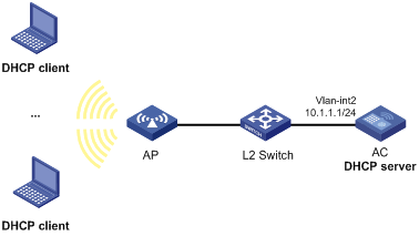
Configuration procedure
1. Assign IP addresses to the interfaces on the DHCP server. (Details not shown.)
2. Configure basic settings on the AC. For more information, see WLAN Configuration Guide.
3. Configure DHCP:
# Enable DHCP.
<AC> system-view
[AC] dhcp enable
# Enable DHCP server on VLAN-interface 2.
[AC] interface vlan-interface 2
[AC-Vlan-interface2] dhcp select server
[AC-Vlan-interface2] quit
# Create DHCP user class ss and configure a match rule to match DHCP requests in which the hardware address is six bytes long and begins with aabb-aabb.
[AC-dhcp-class-ss] if-match rule 1 hardware-address aabb-aabb-0000 mask ffff-ffff-0000
[AC-dhcp-class-ss] quit
# Create DHCP address pool aa.
[AC] dhcp server ip-pool aa
# Specify the subnet for dynamic allocation.
[AC-dhcp-pool-aa] network 10.1.1.0 mask 255.255.255.0
# Enable DHCP user class whitelist.
[AC-dhcp-pool-aa] verify class
# Add DHCP user class ss to the DHCP user class whitelist.
[AC-dhcp-pool-aa] valid class ss
[AC-dhcp-pool-aa] quit
Verifying the configuration
# Verify that clients matching the DHCP user class can obtain IP addresses on subnet 10.1.1.0/24 from the DHCP server. (Details not shown.)
# On the DHCP server, display the IP addresses assigned to the clients.
[AC] display dhcp server ip-in-use
IP address Client identifier/ Lease expiration Type
Hardware address
10.1.1.2 aabb-aabb-ab01 Jan 14 22:25:03 2015 Auto(C)
Primary and secondary subnets configuration example
Network requirements
As shown in Figure 19, the DHCP server (AC) dynamically assigns IP addresses to clients in the LAN.
Configure two subnets in the address pool on the DHCP server: 10.1.1.0/24 as the primary subnet and 10.1.2.0/24 as the secondary subnet. The DHCP server selects IP addresses from the secondary subnet when the primary subnet has no assignable addresses.
The AC also assigns the following parameters:
· The default gateway 10.1.1.254/24 to clients on subnet 10.1.1.0/24.
· The default gateway 10.1.2.254/24 to clients on subnet 10.1.2.0/24.
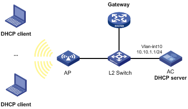
Configuration procedure
# Configure basic settings on the AC. For more information, see WLAN Configuration Guide.
# Enable DHCP
<AC> system-view
[AC] dhcp enable
# Configure the primary and secondary IP addresses of VLAN-interface 10.
[AC] interface vlan-interface 10
[AC-Vlan-interface10] ip address 10.1.1.1 24
[AC-Vlan-interface10] ip address 10.1.2.1 24 sub
# Enable the DHCP server on VLAN-interface 10.
[AC-Vlan-interface10] dhcp select server
[AC-Vlan-interface10] quit
# Create DHCP address pool aa.
[AC] dhcp server ip-pool aa
# Specify the primary subnet and the gateway for dynamic allocation.
[AC-dhcp-pool-aa] network 10.1.1.0 mask 255.255.255.0
[AC-dhcp-pool-aa] gateway-list 10.1.1.254
# Specify the secondary subnet and the gateway for dynamic allocation.
[AC-dhcp-pool-aa] network 10.1.2.0 mask 255.255.255.0 secondary
[AC-dhcp-pool-aa-secondary] gateway-list 10.1.2.254
[AC-dhcp-pool-aa-secondary] quit
[AC-dhcp-pool-aa] quit
Verifying the configuration
# Verify that the DHCP server assigns clients IP addresses and gateway address from the secondary subnet when no address is available from the primary subnet. (Details not shown.)
# Display the primary and secondary subnet IP addresses the DHCP server has assigned. The following is part of the command output.
[AC] display dhcp server ip-in-use
IP address Client identifier/ Lease expiration Type
Hardware address
10.1.1.2 0031-3865-392e-6262- Jan 14 22:25:03 2015 Auto(C)
3363-2e30-3230-352d-
4745-302f-30
10.1.2.2 3030-3030-2e30-3030- Jan 14 22:25:03 2015 Auto(C)
662e-3030-3033-2d45-
7568-6572-1e
DHCP option customization configuration example
Network requirements
As shown in Figure 20, the DHCP server (the device) assigns an IP address, the AC address, a gateway address, and a DNS server address to the AP. Configure the DHCP server as follows:
· Create an address pool, specify the subnet 10.1.1.0/24, and configure the address lease duration as 10 days.
· Specify the gateway address and the DNS server address as 10.1.1.1 and 20.1.1.1.
· Configure Option 43. Specify the AC address as 10.1.1.3. The formats of Option 43 and the PXE server address sub-option are shown in Figure 11 and Figure 13. The value of Option 43 configured on the DHCP server in this example is 80 07 00 00 01 0A 01 01 03.
? The number 80 is the value of the sub-option type.
? The number 07 is the value of the sub-option length.
? The numbers 00 00 are the value of the PXE server type.
? The number 01 indicates the number of servers.
? The numbers 0A 01 01 03 indicate that the IP address of the AC is 10.1.1.3.
· To avoid address conflicts, exclude the IP addresses 10.1.1.1 and 10.1.1.3 of the gateway and the AC from dynamic allocation.
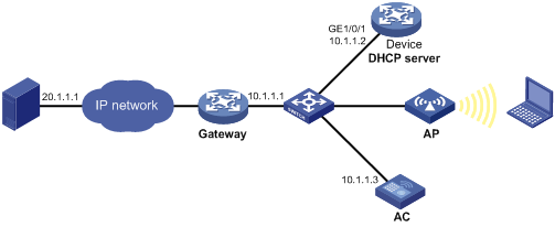
Configuration procedure
1. Specify an IP address for GigabitEthernet 1/0/1 on the device.
<Device> system-view
[Device] interface gigabitethernet 1/0/1
[Device-GigabitEthernet1/0/1] ip address 10.1.1.2 24
[Device-GigabitEthernet1/0/1] quit
2. Configure the DHCP server:
# Enable DHCP.
[Device] dhcp enable
# Enable the DHCP server on GigabitEthernet 1/0/1.
[Device] interface gigabitethernet 1/0/1
[Device-GigabitEthernet1/0/1] ip address dhcp select server
[Device-GigabitEthernet1/0/1] quit
# Exclude the gateway address and the AC address from dynamic allocation.
[Device] dhcp server forbidden-ip 10.1.1.1
[Device] dhcp server forbidden-ip 10.1.1.3
# Configure DHCP address pool 0 for dynamic allocation.
[Device] dhcp server ip-pool 0
# Specify the assignable subnet as 10.1.1.0/24 and the address lease duration as ten days.
[Device-dhcp-pool-0] network 10.1.1.0 mask 255.255.255.0
[Device-dhcp-pool-0] expired day 10
# Specify the gateway address as 10.1.1.1 and the DNS server address as 20.1.1.1.
[Device-dhcp-pool-0] gateway-list 10.1.1.1
[Device-dhcp-pool-0] dns-list 20.1.1.1
# Specify the AC address as 10.1.1.3.
[Device-dhcp-pool-0] option 43 hex 80070000010A010103
Verifying the configuration
# Verify that the AP can obtain an IP address and all other network parameters from the device. (Details not shown.)
# On the DHCP server, display the IP address assigned to the AP.
[Device] display dhcp server ip-in-use
Troubleshooting DHCP server configuration
Failure to obtain a non-conflicting IP address
Symptom
A client's IP address obtained from the DHCP server conflicts with another IP address.
Solution
Another host on the subnet might have the same IP address.
To resolve the problem:
1. Disable the client's network adapter or disconnect the client's network cable. Ping the IP address of the client from another host to check whether there is a host using the same IP address.
2. If a ping response is received, the IP address has been manually configured on a host. Execute the dhcp server forbidden-ip command on the DHCP server to exclude the IP address from dynamic allocation.
3. Enable the network adapter or connect the network cable, release the IP address, and obtain another one on the client. For example, to release the IP address and obtain another one on a Windows XP DHCP client:
a. In Windows environment, execute the cmd command to enter the DOS environment.
b. Enter ipconfig /release to relinquish the IP address.
c. Enter ipconfig /renew to obtain another IP address.
Configuring the DHCP relay agent
Overview
The DHCP relay agent enables clients to get IP addresses from a DHCP server on another subnet. This feature avoids deploying a DHCP server for each subnet to centralize management and reduce investment. Figure 21 shows a typical application of the DHCP relay agent.
Figure 21 DHCP relay agent application
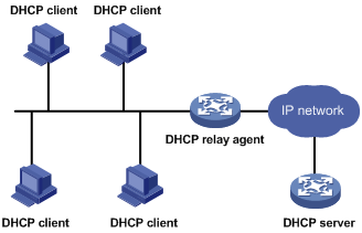
Operation
The DHCP server and client interact with each other in the same way regardless of whether the relay agent exists. For the interaction details, see "IP address allocation process." The following only describes steps related to the DHCP relay agent:
1. After receiving a DHCP-DISCOVER or DHCP-REQUEST broadcast message from a DHCP client, the DHCP relay agent processes the message as follows:
a. Fills the giaddr field of the message with its IP address.
b. Unicasts the message to the designated DHCP server.
2. Based on the giaddr field, the DHCP server returns an IP address and other configuration parameters in a response.
3. The relay agent conveys the response to the client.
Figure 22 DHCP relay agent operation
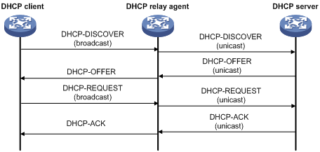
DHCP relay agent support for Option 82
Option 82 records the location information about the DHCP client. It enables the administrator to perform the following tasks:
· Locate the DHCP client for security and accounting purposes.
· Assign IP addresses in a specific range to clients.
For more information about Option 82, see "Relay agent option (Option 82)."
If the DHCP relay agent supports Option 82, it handles DHCP requests by following the strategies described in Table 3.
If a response returned by the DHCP server contains Option 82, the DHCP relay agent removes the Option 82 before forwarding the response to the client.
Table 3 Handling strategies of the DHCP relay agent
|
If a DHCP request has… |
Handling strategy |
The DHCP relay agent… |
|
Option 82 |
Drop |
Drops the message. |
|
Keep |
Forwards the message without changing Option 82. |
|
|
Replace |
Forwards the message after replacing the original Option 82 with the Option 82 padded according to the configured padding format, padding content, and code type. |
|
|
No Option 82 |
N/A |
Forwards the message after adding Option 82 padded according to the configured padding format, padding content, and code type. |
DHCP relay agent configuration task list
|
Tasks at a glance |
|
(Required.) Enabling DHCP |
|
(Required.) Enabling the DHCP relay agent on an interface |
|
(Required.) Specifying DHCP servers on a relay agent |
|
(Optional.) Configuring the DHCP relay agent security features |
|
(Optional.) Configuring the DHCP relay agent to release an IP address |
|
(Optional.) Configuring Option 82 |
|
(Optional.) Setting the DSCP value for DHCP packets sent by the DHCP relay agent |
|
(Optional.) Enabling DHCP server proxy on a DHCP relay agent |
|
(Optional.) Configuring a DHCP relay address pool |
|
(Optional.) Specifying a gateway address for DHCP clients |
|
(Optional.) Enabling client offline detection on the DHCP relay agent |
|
(Optional.) Configuring the DHCP smart relay feature |
Enabling DHCP
You must enable DHCP to validate other DHCP relay agent settings.
To enable DHCP:
|
Step |
Command |
Remarks |
|
1. Enter system view. |
system-view |
N/A |
|
2. Enable DHCP. |
dhcp enable |
By default, DHCP is disabled. |
Enabling the DHCP relay agent on an interface
With the DHCP relay agent enabled, an interface forwards incoming DHCP requests to a DHCP server.
An IP address pool that contains the IP address of the DHCP relay interface must be configured on the DHCP server. Otherwise, the DHCP clients connected to the relay agent cannot obtain correct IP addresses.
To enable the DHCP relay agent on an interface:
|
Step |
Command |
Remarks |
|
1. Enter system view. |
system-view |
N/A |
|
2. Enter interface view. |
interface interface-type interface-number |
N/A |
|
3. Enable the DHCP relay agent. |
dhcp select relay |
By default, when DHCP is enabled, an interface operates in the DHCP server mode. |
Specifying DHCP servers on a relay agent
To improve availability, you can specify several DHCP servers on the DHCP relay agent. When the interface receives request messages from clients, the relay agent forwards them to all DHCP servers.
Follow these guidelines when you specify a DHCP server address on a relay agent:
· The IP address of any specified DHCP server must not reside on the same subnet as the IP address of the relay interface. Otherwise, the clients might fail to obtain IP addresses.
· You can specify a maximum of eight DHCP servers.
To specify a DHCP server address on a relay agent:
|
Command |
Remarks |
|
|
1. Enter system view. |
system-view |
N/A |
|
2. Enter interface view. |
interface interface-type interface-number |
N/A |
|
3. Specify a DHCP server address on the relay agent. |
dhcp relay server-address ip-address |
By default, no DHCP server address is specified on the relay agent. |
Configuring the DHCP relay agent security features
Enabling the DHCP relay agent to record relay entries
Perform this task to enable the DHCP relay agent to automatically record clients' IP-to-MAC bindings (relay entries) after they obtain IP addresses through DHCP.
Some security features use the relay entries to check incoming packets and block packets that do not match any entry. In this way, illegal hosts are not able to access external networks through the relay agent. Examples of the security features are ARP address check, authorized ARP, and IP source guard.
To enable the DHCP relay agent to record relay entries:
|
Step |
Command |
Remarks |
|
1. Enter system view. |
system-view |
N/A |
|
2. Enable the relay agent to record relay entries. |
dhcp relay client-information record |
By default, the relay agent does not record relay entries. |
|
|
NOTE: The DHCP relay agent does not record IP-to-MAC bindings for DHCP clients running on synchronous/asynchronous serial interfaces. |
Enabling periodic refresh of dynamic relay entries
A DHCP client unicasts a DHCP-RELEASE message to the DHCP server to release its IP address. The DHCP relay agent conveys the message to the DHCP server and does not remove the IP-to-MAC entry of the client.
With this feature, the DHCP relay agent uses the following information to periodically send a DHCP-REQUEST message to the DHCP server:
· The IP address of a relay entry.
· The MAC address of the DHCP relay interface.
The relay agent maintains the relay entries depending on what it receives from the DHCP server:
· If the server returns a DHCP-ACK message or does not return any message within an interval, the DHCP relay agent removes the relay entry. In addition, upon receiving the DHCP-ACK message, the relay agent sends a DHCP-RELEASE message to release the IP address.
· If the server returns a DHCP-NAK message, the relay agent keeps the relay entry.
To enable periodic refresh of dynamic relay entries:
|
Step |
Command |
Remarks |
|
1. Enter system view. |
system-view |
N/A |
|
2. Enable periodic refresh of dynamic relay entries. |
dhcp relay client-information refresh enable |
By default, periodic refresh of dynamic relay entries is enabled. |
|
3. Set the refresh interval. |
dhcp relay client-information refresh [ auto | interval interval ] |
By default, the refresh interval is auto, which is calculated based on the number of total relay entries. |
Enabling DHCP starvation attack protection
A DHCP starvation attack occurs when an attacker constantly sends forged DHCP requests using different MAC addresses in the chaddr field to a DHCP server. This exhausts the IP address resources of the DHCP server so legitimate DHCP clients cannot obtain IP addresses. The DHCP server might also fail to work because of exhaustion of system resources. The following methods are available to relieve or prevent such attacks.
· To relieve a DHCP starvation attack that uses DHCP packets encapsulated with different source MAC addresses, you can use one of the following methods:
? Limit the number of ARP entries that a Layer 3 interface can learn.
? Set the MAC learning limit for a Layer 2 port, and disable unknown frame forwarding when the MAC learning limit is reached.
· To prevent a DHCP starvation attack that uses DHCP requests encapsulated with the same source MAC address, you can enable MAC address check on the DHCP relay agent. The DHCP relay agent compares the chaddr field of a received DHCP request with the source MAC address in the frame header. If they are the same, the DHCP relay agent forwards the request to the DHCP server. If not, the relay agent discards the request.
Enable MAC address check only on the DHCP relay agent directly connected to the DHCP clients. A DHCP relay agent changes the source MAC address of DHCP packets before sending them.
A MAC address check entry has an aging time. When the aging time expires, both of the following occur:
· The entry ages out.
· The DHCP relay agent rechecks the validity of DHCP requests sent from the MAC address in the entry.
To enable MAC address check:
|
Step |
Command |
Remarks |
|
1. Enter system view. |
system-view |
N/A |
|
2. Set the aging time for MAC address check entries. |
dhcp relay check mac-address aging-time time |
The default aging time is 30 seconds. This command takes effect only after you execute the dhcp relay check mac-address command. |
|
3. Enter the interface view. |
interface interface-type interface-number |
N/A |
|
4. Enable MAC address check. |
dhcp relay check mac-address |
By default, MAC address check is disabled. |
Configuring the DHCP relay agent to release an IP address
Configure the relay agent to release the IP address for a relay entry. The relay agent sends a DHCP-RELEASE message to the server and meanwhile deletes the relay entry. Upon receiving the DHCP-RELEASE message, the DHCP server releases the IP address.
To configure the DHCP relay agent to release an IP address:
|
Step |
Command |
Remarks |
|
1. Enter system view. |
system-view |
N/A |
|
2. Configure the DHCP relay agent to release an IP address. |
dhcp relay release ip client-ip |
This command can release only the IP addresses in the recorded relay entries. |
Configuring Option 82
Follow these guidelines when you configure Option 82:
· To support Option 82, you must perform related configuration on both the DHCP server and relay agent. For DHCP server Option 82 configuration, see "Enabling handling of Option 82."
· If the handling strategy is replace, configure a padding mode and padding format for Option 82. If the handling strategy is keep or drop, you do not need to configure any padding mode or padding format for Option 82. The settings do not take effect even if you configure them.
· The device name (sysname) must not include spaces if it is configured as the padding content for sub-option 1. Otherwise, the DHCP relay agent will fail to add or replace Option 82.
|
Step |
Command |
Remarks |
|
1. Enter system view. |
system-view |
N/A |
|
2. Enter interface view. |
interface interface-type interface-number |
N/A |
|
3. Enable the relay agent to handle Option 82. |
dhcp relay information enable |
By default, handling of Option 82 is disabled. |
|
4. (Optional.) Configure the strategy for handling DHCP requests that contain Option 82. |
dhcp relay information strategy { drop | keep | replace } |
By default, the handling strategy is replace. |
|
5. (Optional.) Configure the padding mode and padding format for the Circuit ID sub-option. |
dhcp relay information circuit-id { bas | string circuit-id | { normal | verbose [ node-identifier { mac | sysname | user-defined node-identifier } ] [ interface ] } [ format { ascii | hex } ] } |
By default, the padding mode for Circuit ID sub-option is normal, and the padding format is hex. |
|
6. (Optional.) Configure the padding mode and padding format for the Remote ID sub-option. |
dhcp relay information remote-id { { ap-mac | ap-mac-ssid | normal } [ format { ascii | hex } ] | ap-name | ap-name-ssid | string remote-id | sysname } |
By default, the padding mode for the Remote ID sub-option is normal, and the padding format is hex. |
Setting the DSCP value for DHCP packets sent by the DHCP relay agent
The DSCP value of a packet specifies the priority level of the packet and affects the transmission priority of the packet.
To set the DSCP value for DHCP packets sent by the DHCP relay agent:
|
Step |
Command |
Remarks |
|
1. Enter system view. |
system-view |
N/A |
|
2. Set the DSCP value for DHCP packets sent by the DHCP relay agent. |
dhcp dscp dscp-value |
By default, the DSCP value in DHCP packets sent by the DHCP relay agent is 56. |
Enabling DHCP server proxy on a DHCP relay agent
The DHCP server proxy feature isolates DHCP servers from DHCP clients and protects DHCP servers against attacks.
Upon receiving a response from the server, the DHCP server proxy modifies the server's IP address as the relay interface's IP address before sending out the response. The DHCP client takes the DHCP relay agent as the DHCP server.
To configure DHCP server proxy on a DHCP relay agent:
|
Step |
Command |
Remarks |
|
1. Enter system view. |
system-view |
N/A |
|
2. Enter interface view. |
interface interface-type interface-number |
N/A |
|
3. Enable DHCP relay agent and DHCP server proxy on the interface. |
dhcp select relay proxy |
By default, the interface operates in DHCP server mode. |
Configuring a DHCP relay address pool
This feature allows DHCP clients of the same type to obtain IP addresses and other configuration parameters from the DHCP servers specified in the matching relay address pool.
It applies to scenarios where the DHCP relay agent connects to clients of the same access type but classified into different types by their locations. In this case, the relay interface typically has no IP address configured. You can use the gateway-list command to specify the gateway address for clients matching the same relay address pool and bind the gateway address to the device's MAC address. Example network is the IPoE network.
Upon receiving a DHCP DISCOVER or REQUEST from a client that matches a relay address pool, the relay agent processes the packet as follows:
· Fills the giaddr field of the packet with the specified gateway address.
· Forwards the packet to all DHCP servers in the matching relay address pool.
The DHCP servers select an address pool according to the gateway address.
If PPPoE users are in the network, follow these restrictions and guidelines when you configure the relay address pool:
· Enable the DHCP relay agent to record DHCP relay entries by using the dhcp relay client-information record command. When a PPPoE user goes offline, the DHCP relay agent can find a matching relay entry and send a DHCP-RELEASE message to the DHCP server. This mechanism ensures that the DHCP server is aware of the releasing of the IP address in a timely manner.
· The remote-server command also configures the device as a DHCP relay agent. You do not need to enable the DHCP relay agent by using the dhcp select relay command.
To configure a DHCP relay address pool:
|
Step |
Command |
Remarks |
|
1. Enter system view. |
system-view |
N/A |
|
2. Create a DHCP relay address pool and enter its view. |
dhcp server ip-pool pool-name |
By default, no DHCP relay address pool exists. This command is the same for creating DHCP address pools on a DHCP server. However, the relay address pool names are not necessarily the same as the server address pool names. |
|
3. Specify gateway addresses for the clients matching the relay address pool. |
gateway-list ip-address&<1-64> [ export-route ] |
By default, no gateway address is specified. |
|
4. Specify DHCP servers for the relay address pool. |
remote-server ip-address&<1-8> |
By default, no DHCP server is specified for the relay address pool. You can specify a maximum of eight DHCP servers for one relay address pool for high availability. The relay agent forwards DHCP DISCOVER and REQUEST packets to all DHCP servers in the relay address pool. |
Specifying a gateway address for DHCP clients
By default, the DHCP relay agent fills the giaddr field of DHCP DISCOVER and REQUEST packets with the primary IP address of the relay interface. You can specify a gateway address on the relay agent for DHCP clients. The DHCP relay agent uses the specified gateway address to fill the giaddr field of DHCP DISCOVER and REQUEST packets.
To specify a gateway address for DHCP clients:
|
Step |
Command |
Remarks |
|
1. Enter system view. |
system-view |
N/A |
|
2. Enter interface view. |
interface interface-type interface-number |
N/A |
|
3. Specify a gateway address for DHCP clients. |
dhcp relay gateway ip-address |
By default, the DHCP relay agent uses the primary IP address of the relay interface as the clients' gateway address. |
Enabling client offline detection on the DHCP relay agent
When an ARP entry ages out, the client offline detection feature deletes the relay entry for the IP address and sends a RELEASE message to the DHCP server. The feature does not function if an ARP entry is manually deleted.
To enable client offline detection on the DHCP relay agent:
|
Step |
Command |
Remarks |
|
1. Enter system view. |
system-view |
N/A |
|
2. Enable the relay agent to record relay entries. |
dhcp relay client-information record |
By default, the relay agent does not record relay entries. Without relay entries, client offline detection cannot function correctly. |
|
3. Enter interface view. |
interface interface-type interface-number |
N/A |
|
4. Enable the DHCP relay agent. |
dhcp select relay |
By default, when DHCP is enabled, an interface operates in the DHCP server mode. |
|
5. Enable client offline detection. |
dhcp client-detect |
By default, client offline detection is disabled on the DHCP relay agent. |
Configuring the DHCP smart relay feature
The DHCP smart relay feature allows the DHCP relay agent to pad secondary IP addresses when the DHCP server does not send back the DHCP-OFFER message.
The relay agent initially pads its primary IP address to the giaddr field before forwarding a request to the DHCP server. If no DHCP-OFFER is received, the relay agent allows the client to send a maximum of two requests to the DHCP server by using the primary IP address. If no DHCP-OFFER is returned after two retries, the relay agent switches to a secondary IP address. If the DHCP server still does not respond, the next secondary IP address is used. After the secondary IP addresses are all tried and the DHCP server does not respond, the relay agent repeats the process by starting from the primary IP address.
Without this feature, the relay agent only pads the primary IP address to the giaddr field of all requests.
On a relay agent where relay address pools and gateway addresses are configured, the smart relay feature starts the process from the first gateway address. For more information about the relay address pool configuration, see "Configuring a DHCP relay address pool."
To configure the DHCP smart relay feature for a DHCP server's network:
|
Step |
Command |
Remarks |
|
1. Enter system view. |
system-view |
N/A |
|
2. Enter interface view. |
interface interface-type interface-number |
N/A |
|
3. Enable the DHCP relay agent. |
dhcp select relay |
By default, an interface operates in the DHCP server mode when DHCP is enabled. |
|
4. Assign primary and secondary IP addresses to the DHCP relay agent. |
ip address ip-address { mask-length | mask } [ sub ] |
By default, the DHCP relay agent does not have any IP addresses. |
|
5. Return to system view. |
quit |
N/A |
|
6. Enable the DHCP smart relay feature. |
dhcp smart-relay enable |
By default, the DHCP smart relay feature is disabled. |
To configure the DHCP smart relay feature for a network with relay address pools configured:
|
Step |
Command |
Remarks |
|
|
1. Enter system view. |
system-view |
N/A |
|
|
2. Enter interface view. |
interface interface-type interface-number |
N/A |
|
|
3. Enable the DHCP relay agent. |
dhcp select relay |
By default, an interface operates in the DHCP server mode when DHCP is enabled. |
|
|
4. Return to system view. |
quit |
N/A |
|
|
5. Create a DHCP relay address pool and enter its view. |
dhcp server ip-pool pool-name |
By default, no DHCP relay address pool exists. This command is the same for creating DHCP address pools on a DHCP server. However, the relay address pool names are not necessarily the same as the server address pool names. |
|
|
6. Specify gateway addresses for the clients matching the relay address pool. |
gateway-list ip-address&<1-64> [ export-route ] |
By default, the relay address pool does not have any gateway addresses. |
|
|
7. Specify DHCP servers for the relay address pool. |
remote-server ip-address&<1-8> |
By default, the relay address pool does not have any DHCP server IP addresses. You can specify a maximum of eight DHCP servers for one relay address pool for high availability. The relay agent forwards DHCP-DISCOVER and DHCP-REQUEST packets to all DHCP servers in the relay address pool. |
|
|
8. Return to system view. |
quit |
N/A |
|
|
9. Enable the DHCP smart relay feature. |
dhcp smart-relay enable |
By default, the DHCP smart relay feature is disabled. |
|
Displaying and maintaining the DHCP relay agent
Execute display commands in any view and reset commands in user view.
|
Task |
Command |
|
Display information about DHCP servers on an interface. |
display dhcp relay server-address [ interface interface-type interface-number ] |
|
Display Option 82 configuration information on the DHCP relay agent. |
display dhcp relay information [ interface interface-type interface-number ] |
|
Display relay entries on the DHCP relay agent. |
display dhcp relay client-information [ interface interface-type interface-number | ip ip-address ] |
|
Display packet statistics on the DHCP relay agent. |
display dhcp relay statistics [ interface interface-type interface-number ] |
|
Display MAC address check entries on the DHCP relay agent. |
display dhcp relay check mac-address |
|
Clear relay entries on the DHCP relay agent. |
reset dhcp relay client-information [ interface interface-type interface-number | ip ip-address ] |
|
Clear packet statistics on the DHCP relay agent. |
reset dhcp relay statistics [ interface interface-type interface-number ] |
DHCP relay agent configuration example
Network requirements
As shown in Figure 23, configure the DHCP relay agent on the AC. The DHCP relay agent enables DHCP clients to obtain IP addresses and other configuration parameters from the DHCP server on another subnet.
The DHCP relay agent and server are on different subnets. Configure static or dynamic routing to make them reachable to each other.
Perform the configuration on the DHCP server to guarantee the client-server communication. For DHCP server configuration information, see "DHCP server configuration examples."
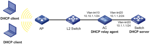
Configuration procedure
# Assign IP addresses to the interfaces. (Details not shown.)
# Configure basic settings on the AC. For more information, see WLAN Configuration Guide.
# Enable DHCP.
<AC> system-view
[AC] dhcp enable
# Enable the DHCP relay agent on VLAN-interface 10.
[AC] interface vlan-interface 10
[AC-Vlan-interface10] dhcp select relay
# Specify the IP address of the DHCP server on the relay agent.
[AC-Vlan-interface10] dhcp relay server-address 10.1.1.1
Verifying the configuration
# Verify that DHCP clients can obtain IP addresses and all other network parameters from the DHCP server through the DHCP relay agent. (Details not shown.)
# Display the statistics of DHCP packets forwarded by the DHCP relay agent.
[AC] display dhcp relay statistics
# Display relay entries if you have enabled relay entry recording on the DHCP relay agent.
[AC] display dhcp relay client-information
Troubleshooting DHCP relay agent configuration
Failure of DHCP clients to obtain configuration parameters through the DHCP relay agent
Symptom
DHCP clients cannot obtain configuration parameters through the DHCP relay agent.
Solution
Some problems might occur with the DHCP relay agent or server configuration.
To locate the problem, enable debugging and execute the display command on the DHCP relay agent to view the debugging information and interface state information.
Check that:
· DHCP is enabled on the DHCP server and relay agent.
· The DHCP server has an address pool on the same subnet as the DHCP clients.
· The DHCP server and DHCP relay agent can reach each other.
· The DHCP server address specified on the DHCP relay interface connected to the DHCP clients is correct.
Configuring the DHCP client
With DHCP client enabled, an interface uses DHCP to obtain configuration parameters from the DHCP server, for example, an IP address.
The DHCP client configuration is supported only on Layer 3 Ethernet interfaces (or subinterfaces), VLAN interfaces, and Layer 3 aggregate interfaces.
Enabling the DHCP client on an interface
Follow these guidelines when you enable the DHCP client on an interface:
· On some device models, if the number of IP address request failures reaches the system-defined amount, the DHCP client-enabled interface uses a default IP address.
· An interface can be configured to acquire an IP address in multiple ways. The new configuration overwrites the old.
· Secondary IP addresses cannot be configured on an interface that is enabled with the DHCP client.
· If the interface obtains an IP address on the same segment as another interface on the device, the interface does not use the assigned address. Instead, it requests a new IP address from the DHCP server.
To enable the DHCP client on an interface:
|
Step |
Command |
Remarks |
|
1. Enter system view. |
system-view |
N/A |
|
2. Enter interface view. |
interface interface-type interface-number |
N/A |
|
3. Configure an interface to use DHCP for IP address acquisition. |
ip address dhcp-alloc |
By default, an interface does not use DHCP for IP address acquisition. |
Configuring a DHCP client ID for an interface
A DHCP client ID is added to the DHCP option 61. A DHCP server can specify IP addresses for clients based on the DHCP client ID.
Make sure the IDs for different DHCP clients are unique.
To configure a DHCP client ID for an interface:
|
Step |
Command |
Remarks |
|
1. Enter system view. |
system-view |
N/A |
|
2. Enter interface view. |
interface interface-type interface-number |
N/A |
|
3. Configure a DHCP client ID for the interface. |
dhcp client identifier { ascii string | hex string | mac interface-type interface-number } |
By default, an interface generates the DHCP client ID based on its MAC address. If the interface has no MAC address, it uses the MAC address of the first Ethernet interface to generate its client ID. |
|
4. Verify the client ID configuration. |
display dhcp client [ verbose ] [ interface interface-type interface-number ] |
DHCP client ID includes ID type and type value. Each ID type has a fixed type value. You can check the fields for the client ID to verify which type of client ID is used: · If an ASCII string is used as the client ID, the type value is 00. · If a hex string is used as the client ID, the type value is the first two characters in the string. · If the MAC address of an interface is used as the client ID, the type value is 01. |
Enabling duplicated address detection
DHCP client detects IP address conflict through ARP packets. An attacker can act as the IP address owner to send an ARP reply. The spoofing attack makes the client unable to use the IP address assigned by the server. H3C recommends you to disable duplicate address detection when ARP attacks exist on the network.
To enable duplicated address detection:
|
Step |
Command |
Remarks |
|
1. Enter system view. |
system-view |
N/A |
|
2. Enable duplicate address detection. |
dhcp client dad enable |
By default, the duplicate address detection feature is enabled on an interface. |
Setting the DSCP value for DHCP packets sent by the DHCP client
The DSCP value of a packet specifies the priority level of the packet and affects the transmission priority of the packet.
To set the DSCP value for DHCP packets sent by the DHCP client:
|
Step |
Command |
Remarks |
|
1. Enter system view. |
system-view |
N/A |
|
2. Set the DSCP value for DHCP packets sent by the DHCP client. |
dhcp client dscp dscp-value |
By default, the DSCP value in DHCP packets sent by the DHCP client is 56. |
Displaying and maintaining the DHCP client
Execute display command in any view.
|
Task |
Command |
|
Display DHCP client information. |
display dhcp client [ verbose ] [ interface interface-type interface-number ] |
Configuring DHCP snooping
Overview
DHCP snooping works between the DHCP client and server, or between the DHCP client and DHCP relay agent. It guarantees that DHCP clients obtain IP addresses from authorized DHCP servers. Also, it records IP-to-MAC bindings of DHCP clients (called DHCP snooping entries) for security purposes.
DHCP snooping does not work between the DHCP server and DHCP relay agent.
DHCP snooping defines trusted and untrusted ports to make sure clients obtain IP addresses only from authorized DHCP servers.
· Trusted—A trusted port can forward DHCP messages correctly to make sure the clients get IP addresses from authorized DHCP servers.
· Untrusted—An untrusted port discards received DHCP-ACK and DHCP-OFFER messages to prevent unauthorized servers from assigning IP addresses.
DHCP snooping reads DHCP-ACK messages received from trusted ports and DHCP-REQUEST messages to create DHCP snooping entries. A DHCP snooping entry includes the MAC and IP addresses of a client, the port that connects to the DHCP client, and the VLAN.
The following features need to use DHCP snooping entries:
· ARP fast-reply—Uses DHCP snooping entries to reduce ARP broadcast traffic. For more information, see "Configuring ARP fast-reply."
· ARP detection—Uses DHCP snooping entries to filter ARP packets from unauthorized clients. For more information, see Security Configuration Guide.
· IP source guard—Uses DHCP snooping entries to filter illegal packets on a per-port basis. For more information, see Security Configuration Guide.
Application of trusted and untrusted ports
Configure ports facing the DHCP server as trusted ports, and configure other ports as untrusted ports.
As shown in Figure 24, configure the DHCP snooping device's port that is connected to the DHCP server as a trusted port. The trusted port forwards response messages from the DHCP server to the client. The untrusted port connected to the unauthorized DHCP server discards incoming DHCP response messages.
Figure 24 Trusted and untrusted ports
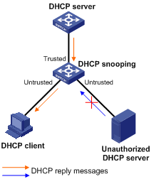
In a cascaded network as shown in Figure 25, configure the DHCP snooping devices' ports facing the DHCP server as trusted ports. To save system resources, you can enable only the untrusted ports directly connected to the DHCP clients to record DHCP snooping entries.
Figure 25 Trusted and untrusted ports in a cascaded network
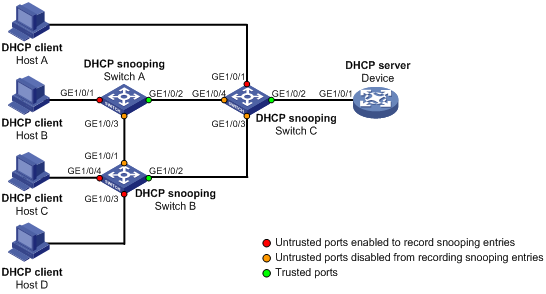
DHCP snooping support for Option 82
Option 82 records the location information about the DHCP client so the administrator can locate the DHCP client for security and accounting purposes. For more information about Option 82, see "Relay agent option (Option 82)."
DHCP snooping uses the same strategies as the DHCP relay agent to handle Option 82 for DHCP request messages, as shown in Table 4. If a response returned by the DHCP server contains Option 82, DHCP snooping removes Option 82 before forwarding the response to the client. If the response contains no Option 82, DHCP snooping forwards it directly.
|
If a DHCP request has… |
Handling strategy |
DHCP snooping… |
|
Option 82 |
Drop |
Drops the message. |
|
Keep |
Forwards the message without changing Option 82. |
|
|
Replace |
Forwards the message after replacing the original Option 82 with the Option 82 padded according to the configured padding format, padding content, and code type. |
|
|
No Option 82 |
N/A |
Forwards the message after adding the Option 82 padded according to the configured padding format, padding content, and code type. |
Command and hardware compatibility
The WX1800H series access controllers do not support the slot keyword or the slot-number argument.
DHCP snooping configuration task list
The DHCP snooping configuration does not take effect on a Layer 2 Ethernet interface that is an aggregation member port. The configuration takes effect when the interface leaves the aggregation group.
|
Tasks at a glance |
|
(Required.) Configuring basic DHCP snooping |
|
(Optional.) Configuring Option 82 |
|
(Optional.) Configuring DHCP snooping entry auto backup |
|
(Optional.) Enabling DHCP starvation attack protection |
|
(Optional.) Enabling DHCP-REQUEST attack protection |
|
(Optional.) Setting the maximum number of DHCP snooping entries |
|
(Optional.) Configuring DHCP packet rate limit |
|
(Optional.) Configuring a DHCP packet blocking port |
|
(Optional.) Enabling DHCP snooping logging |
Configuring basic DHCP snooping
Follow these guidelines when you configure basic DHCP snooping:
· Specify the ports connected to authorized DHCP servers as trusted ports to make sure that DHCP clients can obtain valid IP addresses. The trusted ports and the ports connected to DHCP clients must be in the same VLAN.
· You can specify the following interfaces as trusted ports: Layer 2 Ethernet interfaces, and Layer 2 aggregate interfaces. For more information about aggregate interfaces, see Layer 2—LAN Switching Configuration Guide.
· The DHCP snooping configuration on a Layer 2 Ethernet interface that has been added to an aggregation group does not take effect unless the interface leaves the aggregation group.
To configure basic DHCP snooping:
|
Step |
Command |
Remarks |
|
1. Enter system view. |
system-view |
N/A |
|
2. Enable DHCP snooping. |
dhcp snooping enable |
By default, DHCP snooping is disabled. |
|
3. Enter interface view. |
interface interface-type interface-number |
This interface must connect to the DHCP server. |
|
4. Specify the port as a trusted port. |
dhcp snooping trust |
By default, all ports are untrusted ports after DHCP snooping is enabled. |
|
5. Return to system view. |
quit |
N/A |
|
6. Enter interface view. |
interface interface-type interface-number |
This interface must connect to the DHCP client. |
|
7. (Optional.) Enable the recording of DHCP snooping entries. |
By default, the recording of DHCP snooping entries is disabled. |
Configuring Option 82
Follow these guidelines when you configure Option 82:
· The Option 82 configuration on a Layer 2 Ethernet interface that has been added to an aggregation group does not take effect unless the interface leaves the aggregation group.
· To support Option 82, you must configure Option 82 on both the DHCP server and the DHCP snooping device. For information about configuring Option 82 on the DHCP server, see "Enabling handling of Option 82."
· If the handling strategy is replace, configure a padding mode and padding format for Option 82. If the handling strategy is keep or drop, you do not need to configure any padding mode or padding format for Option 82. The settings do not take effect even if you configure them.
· If Option 82 contains the device name, the device name must contain no spaces. Otherwise, DHCP snooping drops the message. You can use the sysname command to specify the device name. For more information about this command, see Fundamentals Command Reference.
· DHCP snooping uses "outer VLAN tag.inner VLAN tag" to fill the VLAN ID field of sub-option 1 in verbose padding format if either of the following conditions exists:
? DHCP snooping and QinQ work together.
? DHCP snooping receives a DHCP packet with two VLAN tags.
For example, if the outer VLAN tag is 10 and the inner VLAN tag is 20, the VLAN ID field is 000a.0014. The hexadecimal digit a represents the outer VLAN tag 10, and the hexadecimal digit 14 represents the inner VLAN tag 20.
· The device name (sysname) must not include spaces if it is configured as the padding content for sub-option 1. Otherwise, the DHCP snooping device will fail to add or replace Option 82.
To configure DHCP snooping to support Option 82:
|
Step |
Command |
Remarks |
|
1. Enter system view. |
system-view |
N/A |
|
2. Enter interface view. |
interface interface-type interface-number |
N/A |
|
3. Enable DHCP snooping to support Option 82. |
dhcp snooping information enable |
By default, DHCP snooping does not support Option 82. |
|
4. (Optional.) Configure a handling strategy for DHCP requests that contain Option 82. |
dhcp snooping information strategy { drop | keep | replace } |
By default, the handling strategy is replace. |
|
5. (Optional.) Configure the padding mode and padding format for the Circuit ID sub-option. |
dhcp snooping information circuit-id { [ vlan vlan-id ] string circuit-id | { normal | verbose [ node-identifier { mac | sysname | user-defined node-identifier } ] } [ format { ascii | hex } ] } |
By default, the padding mode is normal and the padding format is hex for the Circuit ID sub-option. |
|
6. (Optional.) Configure the padding mode and padding format for the Remote ID sub-option. |
dhcp snooping information remote-id { normal [ format { ascii | hex } ] | [ vlan vlan-id ] string remote-id | sysname } |
By default, the padding mode is normal and the padding format is hex for the Remote ID sub-option. |
Configuring DHCP snooping entry auto backup
The auto backup feature saves DHCP snooping entries to a backup file, and allows the DHCP snooping device to download the entries from the backup file at device reboot. The entries on the DHCP snooping device cannot survive a reboot. The auto backup helps the security features provide services if these features (such as IP source guard) must use DHCP snooping entries for user authentication.
|
|
NOTE: If you disable DHCP snooping with the undo dhcp snooping enable command, the device deletes all DHCP snooping entries, including those stored in the backup file. |
To save DHCP snooping entries:
|
Step |
Command |
Remarks |
|
1. Enter system view. |
system-view |
N/A |
|
2. Configure the DHCP snooping device to back up DHCP snooping entries to a file. |
dhcp snooping binding database filename { filename | url url [ username username [ password { cipher | simple } string ] ] } |
By default, the DHCP snooping device does not back up DHCP snooping entries. With this command executed, the DHCP snooping device backs up DHCP snooping entries immediately and runs auto backup. This command automatically creates the file if you specify a non-existent file. |
|
3. (Optional.) Manually save DHCP snooping entries to the backup file. |
dhcp snooping binding database update now |
N/A |
|
4. (Optional.) Set the waiting time after a DHCP snooping entry change for the DHCP snooping device to update the backup file. |
dhcp snooping binding database update interval interval |
The default waiting time is 300 seconds. When a DHCP snooping entry is learned, updated, or removed, the waiting period starts. The DHCP snooping device updates the backup file when the specified waiting period is reached. All changed entries during the period will be saved to the backup file. If no DHCP snooping entry changes, the backup file is not updated. |
Enabling DHCP starvation attack protection
A DHCP starvation attack occurs when an attacker constantly sends forged DHCP requests that contain identical or different sender MAC addresses in the chaddr field to a DHCP server. This attack exhausts the IP address resources of the DHCP server so legitimate DHCP clients cannot obtain IP addresses. The DHCP server might also fail to work because of exhaustion of system resources. For information about the fields of DHCP packet, see "DHCP message format."
You can prevent DHCP starvation attacks in the following ways:
· If the forged DHCP requests contain different sender MAC addresses, use the mac-address max-mac-count command to set the MAC learning limit on a Layer 2 port. For more information about the command, see Layer 2—LAN Switching Command Reference.
· If the forged DHCP requests contain the same sender MAC address, perform this task to enable MAC address check for DHCP snooping. This feature compares the chaddr field of a received DHCP request with the source MAC address field in the frame header. If they are the same, the request is considered valid and forwarded to the DHCP server. If not, the request is discarded.
To enable MAC address check:
|
Step |
Command |
Remarks |
|
1. Enter system view. |
system-view |
N/A |
|
2. Enter interface view. |
interface interface-type interface-number |
N/A |
|
3. Enable MAC address check. |
dhcp snooping check mac-address |
By default, MAC address check is disabled. |
Enabling DHCP-REQUEST attack protection
DHCP-REQUEST messages include DHCP lease renewal packets, DHCP-DECLINE packets, and DHCP-RELEASE packets. This feature prevents the unauthorized clients that forge the DHCP-REQUEST messages from attacking the DHCP server.
Attackers can forge DHCP lease renewal packets to renew leases for legitimate DHCP clients that no longer need the IP addresses. These forged messages disable the victim DHCP server from releasing the IP addresses.
Attackers can also forge DHCP-DECLINE or DHCP-RELEASE packets to terminate leases for legitimate DHCP clients that still need the IP addresses.
To prevent such attacks, you can enable DHCP-REQUEST check. This feature uses DHCP snooping entries to check incoming DHCP-REQUEST messages.
· If a matching entry is found for a message, this feature compares the entry with the message information.
? If they are consistent, the message is considered as valid and forwarded to the DHCP server.
? If they are different, the message is considered as a forged message and is discarded.
· If no matching entry is found, the message is considered valid and forwarded to the DHCP server.
To enable DHCP-REQUEST check:
|
Step |
Command |
Remarks |
|
1. Enter system view. |
system-view |
N/A |
|
2. Enter interface view. |
interface interface-type interface-number |
N/A |
|
3. Enable DHCP-REQUEST check. |
dhcp snooping check request-message |
By default, DHCP-REQUEST check is disabled. You can enable DHCP-REQUEST check only on Layer 2 Ethernet interfaces, and Layer 2 aggregate interfaces. |
Setting the maximum number of DHCP snooping entries
Perform this task to prevent the system resources from being overused.
To set the maximum number of DHCP snooping entries:
|
Step |
Command |
Remarks |
|
1. Enter system view. |
system-view |
N/A |
|
2. Enter interface view. |
interface interface-type interface-number |
N/A |
|
3. Set the maximum number of DHCP snooping entries for the interface to learn. |
dhcp snooping max-learning-num max-number |
By default, the number of DHCP snooping entries for an interface to learn is unlimited. |
Configuring DHCP packet rate limit
Perform this task to set the maximum rate at which an interface can receive DHCP packets. This feature discards exceeding DHCP packets to prevent attacks that send large numbers of DHCP packets.
To configure DHCP packet rate limit:
|
Step |
Command |
Remarks |
|
1. Enter system view. |
system-view |
N/A |
|
2. Enter interface view. |
interface interface-type interface-number |
N/A |
|
3. Set the maximum rate at which the interface can receive DHCP packets. |
dhcp snooping rate-limit rate |
By default, incoming DHCP packets are not rate limited. You can configure this command only on Layer 2 Ethernet interfaces, and Layer 2 aggregate interfaces. The rate set on the Layer 2 aggregate interface applies to all members of the aggregate interface. If a member interface leaves the aggregation group, it uses the rate set in its Ethernet interface view. |
Configuring a DHCP packet blocking port
Perform this task to configure a port as a DHCP packet blocking port. This blocking port drops all incoming DHCP requests.
To configure a DHCP packet blocking port:
|
Step |
Command |
Remarks |
|
1. Enter system view. |
system-view |
N/A |
|
2. Enter interface view. |
interface interface-type interface-number |
N/A |
|
3. Configure the port to block DHCP requests. |
dhcp snooping deny |
By default, the port does not block DHCP requests. |
Enabling DHCP snooping logging
The DHCP snooping logging feature enables the DHCP snooping device to generate DHCP snooping logs and send them to the information center. For information about the log destination and output rule configuration in the information center, see Network Management and Monitoring Configuration Guide.
As a best practice, disable this feature if the log generation affects the device performance.
To enable DHCP snooping logging:
|
Step |
Command |
Remarks |
|
1. Enter system view. |
system-view |
N/A |
|
2. Enable DHCP snooping logging. |
dhcp snooping log enable |
By default, DHCP snooping logging is disabled. |
Displaying and maintaining DHCP snooping
Execute display commands in any view, and reset commands in user view.
|
Task |
Command |
Remarks |
|
Display DHCP snooping entries. |
display dhcp snooping binding [ ip ip-address [ vlan vlan-id ] ] |
Available in any view. |
|
Display Option 82 configuration information on the DHCP snooping device. |
display dhcp snooping information { all | interface interface-type interface-number } |
Available in any view. |
|
Display DHCP packet statistics on the DHCP snooping device. |
display dhcp snooping packet statistics [ slot slot-number ] |
Available in any view. |
|
Display information about trusted ports. |
display dhcp snooping trust |
Available in any view. |
|
Display information about the file that stores DHCP snooping entries. |
display dhcp snooping binding database |
Available in any view. |
|
Clear DHCP snooping entries. |
reset dhcp snooping binding { all | ip ip-address [ vlan vlan-id ] } |
Available in user view. |
|
Clear DHCP packet statistics on the DHCP snooping device. |
reset dhcp snooping packet statistics [ slot slot-number ] |
Available in user view. |
DHCP snooping configuration examples
Basic DHCP snooping configuration example
Network requirements
As shown in Figure 26:
· Configure the port GigabitEthernet 1/0/1 connected to the DHCP server as a trusted port.
· Configure other ports as untrusted ports.
· Enable DHCP snooping to record clients' IP-to-MAC bindings by reading DHCP-ACK messages received from the trusted port and DHCP-REQUEST messages.
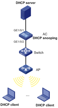
Configuration procedure
# Configure WLAN access on the AC. For more information about WLAN access configuration, see WLAN Configuration Guide. (Details not shown.)
# Enable DHCP snooping.
<AC> system-view
[AC] dhcp snooping enable
# Configure GigabitEthernet 1/0/1 as a trusted port.
[AC] interface gigabitethernet 1/0/1
[AC-GigabitEthernet1/0/1] dhcp snooping trust
[AC-GigabitEthernet1/0/1] quit
# Enable DHCP snooping to record clients' IP-to-MAC bindings on GigabitEthernet 1/0/2.
[AC] interface gigabitethernet 1/0/2
[AC-GigabitEthernet1/0/2] dhcp snooping binding record
[AC-GigabitEthernet1/0/2] quit
Verifying the configuration
# Verify that the DHCP client can obtain an IP address and other configuration parameters only from the DHCP server. (Details not shown.)
# Display the DHCP snooping entry recorded for the client.
[AC] display dhcp snooping binding
Configuring the BOOTP client
BOOTP client configuration applies only to Layer 3 Ethernet interfaces (including subinterfaces), Layer 3 aggregate interfaces, and VLAN interfaces.
BOOTP application
An interface that acts as a BOOTP client can use BOOTP to obtain information (such as IP address) from the BOOTP server.
To use BOOTP, an administrator must configure a BOOTP parameter file for each BOOTP client on the BOOTP server. The parameter file contains information such as MAC address and IP address of a BOOTP client. When a BOOTP client sends a request to the BOOTP server, the BOOTP server searches for the BOOTP parameter file and returns the corresponding configuration information.
BOOTP is usually used in relatively stable environments. In network environments that change frequently, DHCP is more suitable.
Because a DHCP server can interact with a BOOTP client, you can use the DHCP server to assign an IP address to the BOOTP client. You do not need to configure a BOOTP server.
Obtaining an IP address dynamically
A BOOTP client dynamically obtains an IP address from a BOOTP server as follows:
1. The BOOTP client broadcasts a BOOTP request, which contains its own MAC address.
2. Upon receiving the request, the BOOTP server searches the configuration file for the IP address and other information according to the BOOTP client's MAC address.
3. The BOOTP server returns a BOOTP response to the BOOTP client.
4. The BOOTP client obtains the IP address from the received response.
A DHCP server can take the place of the BOOTP server in the following dynamic IP address acquisition.
Protocols and standards
· RFC 951, Bootstrap Protocol (BOOTP)
· RFC 2132, DHCP Options and BOOTP Vendor Extensions
· RFC 1542, Clarifications and Extensions for the Bootstrap Protocol
Configuring an interface to use BOOTP for IP address acquisition
|
Step |
Command |
Remarks |
|
1. Enter system view. |
system-view |
N/A |
|
2. Enter interface view. |
interface interface-type interface-number |
N/A |
|
3. Configure an interface to use BOOTP for IP address acquisition. |
ip address bootp-alloc |
By default, an interface does not use BOOTP for IP address acquisition. |
Displaying and maintaining BOOTP client
Execute display command in any view.
|
Task |
Command |
|
Display BOOTP client information. |
display bootp client [ interface interface-type interface-number ] |
Configuring DNS
Overview
Domain Name System (DNS) is a distributed database used by TCP/IP applications to translate domain names into IP addresses. The domain name-to-IP address mapping is called a DNS entry.
DNS services can be static or dynamic. After a user specifies a name, the device checks the static name resolution table for an IP address. If no IP address is available, it contacts the DNS server for dynamic name resolution, which takes more time than static name resolution. To improve efficiency, you can put frequently queried name-to-IP address mappings in the local static name resolution table.
Static domain name resolution
Static domain name resolution means manually creating mappings between domain names and IP addresses. For example, you can create a static DNS mapping for a device so that you can Telnet to the device by using the domain name.
Dynamic domain name resolution
Resolution process
1. A user program sends a name query to the resolver of the DNS client.
2. The DNS resolver looks up the local domain name cache for a match. If the resolver finds a match, it sends the corresponding IP address back. If not, it sends a query to the DNS server.
3. The DNS server looks up the corresponding IP address of the domain name in its DNS database. If no match is found, the server sends a query to other DNS servers. This process continues until a result, whether successful or not, is returned.
4. After receiving a response from the DNS server, the DNS client returns the resolution result to the user program.
Figure 27 shows the relationship between the user program, DNS client, and DNS server.
The DNS client includes the resolver and cache. The user program and DNS client can run on the same device or different devices. The DNS server and the DNS client usually run on different devices.
Figure 27 Dynamic domain name resolution
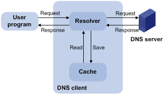
Dynamic domain name resolution allows the DNS client to store latest DNS entries in the dynamic domain name cache. The DNS client does not need to send a request to the DNS server for a repeated query within the aging time. To make sure the entries from the DNS server are up to date, a DNS entry is removed when its aging timer expires. The DNS server determines how long a mapping is valid, and the DNS client obtains the aging information from DNS responses.
DNS suffixes
You can configure a domain name suffix list so that the resolver can use the list to supply the missing part of an incomplete name.
For example, you can configure com as the suffix for aabbcc.com. The user only needs to enter aabbcc to obtain the IP address of aabbcc.com. The resolver adds the suffix and delimiter before passing the name to the DNS server.
The name resolver handles the queries based on the domain names that the user enters:
· If the user enters a domain name without a dot (.) (for example, aabbcc), the resolver considers the domain name as a host name. It adds a DNS suffix to the host name before performing the query operation. If no match is found for any host name and suffix combination, the resolver uses the user-entered domain name (for example, aabbcc) for the IP address query.
· If the user enters a domain name with a dot (.) among the letters (for example, www.aabbcc), the resolver directly uses this domain name for the query operation. If the query fails, the resolver adds a DNS suffix for another query operation.
· If the user enters a domain name with a dot (.) at the end (for example, aabbcc.com.), the resolver considers the domain name an FQDN and returns the successful or failed query result. The dot at the end of the domain name is considered a terminating symbol.
The device supports static and dynamic DNS client services.
If an alias is configured for a domain name on the DNS server, the device can resolve the alias into the IP address of the host.
DNS proxy
As shown in Figure 28, the DNS proxy performs the following operations:
· Forwards the request from the DNS client to the designated DNS server.
· Conveys the reply from the DNS server to the client.
The DNS proxy simplifies network management. When the DNS server address is changed, you can change the configuration only on the DNS proxy instead of on each DNS client.
Figure 28 DNS proxy application
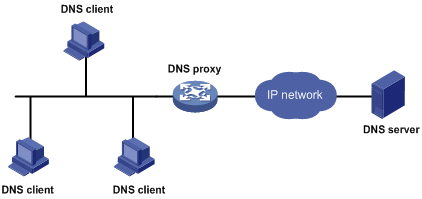
A DNS proxy operates as follows:
1. A DNS client considers the DNS proxy as the DNS server, and sends a DNS request to the DNS proxy. The destination address of the request is the IP address of the DNS proxy.
2. The DNS proxy searches the local static domain name resolution table and dynamic domain name resolution cache after receiving the request. If the requested information is found, the DNS proxy returns a DNS reply to the client.
3. If the requested information is not found, the DNS proxy sends the request to the designated DNS server for domain name resolution.
4. After receiving a reply from the DNS server, the DNS proxy records the IP address-to-domain name mapping and forwards the reply to the DNS client.
If no DNS server is designated or no route is available to the designated DNS server, the DNS proxy does not forward DNS requests.
DNS spoofing
DNS spoofing is applied to the dial-up network, as shown in Figure 29.
· The device connects to a PSTN/ISDN network through a dial-up interface. The device triggers the establishment of a dial-up connection only when packets are to be forwarded through the dial-up interface.
· The device acts as a DNS proxy and is specified as a DNS server on the hosts. After the dial-up connection is established, the device dynamically obtains the DNS server address through DHCP or another autoconfiguration mechanism.
Figure 29 DNS spoofing application
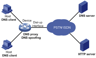
The DNS proxy does not have the DNS server address or cannot reach the DNS server after startup. A host accesses the HTTP server in the following steps:
1. The host sends a DNS request to the device to resolve the domain name of the HTTP server into an IP address.
2. Upon receiving the request, the device searches the local static and dynamic DNS entries for a match. Because no match is found, the device spoofs the host by replying a configured IP address. The device must have a route to the IP address with the dial-up interface as the output interface.
The IP address configured for DNS spoofing is not the actual IP address of the requested domain name. Therefore, the TTL field is set to 0 in the DNS reply. When the DNS client receives the reply, it creates a DNS entry and ages it out immediately.
3. Upon receiving the reply, the host sends an HTTP request to the replied IP address.
4. When forwarding the HTTP request through the dial-up interface, the device performs the following operations:
? Establishes a dial-up connection with the network.
? Dynamically obtains the DNS server address through DHCP or another autoconfiguration mechanism.
5. Because the DNS entry ages out immediately upon creation, the host sends another DNS request to the device to resolve the HTTP server domain name.
6. The device operates the same as a DNS proxy. For more information, see "DNS proxy."
7. After obtaining the IP address of the HTTP server, the host can access the HTTP server.
Without DNS spoofing, the device forwards the DNS requests from the host to the DNS server if it cannot find a matching local DNS entry. However, the device cannot obtain the DNS server address, because no dial-up connection is established. Therefore, the device cannot forward or answer the requests from the client. DNS resolution fails, and the client cannot access the HTTP server.
DNS configuration task list
|
Tasks at a glance |
|
Perform one of the following tasks: |
|
(Optional.) Configuring the DNS proxy |
|
(Optional.) Configuring DNS spoofing |
|
(Optional.) Specifying the source interface for DNS packets |
|
(Optional.) Configuring the DNS trusted interface |
|
(Optional.) Setting the DSCP value for outgoing DNS packets |
Configuring the IPv4 DNS client
Configuring static domain name resolution
Static domain name resolution allows applications such as Telnet to contact hosts by using host names instead of IPv4 addresses.
Follow these guidelines when you configure static domain name resolution:
· Each host name maps to only one IPv4 address. The most recent configuration for a host name takes effect.
· You can configure a maximum of 1024 IPv4 DNS entries.
To configure static domain name resolution:
|
Step |
Command |
Remarks |
|
1. Enter system view. |
system-view |
N/A |
|
2. Configure a mapping between a host name and an IPv4 address. |
ip host host-name ip-address |
By default, no mapping between a host name and an IPv4 address is configured. |
Configuring dynamic domain name resolution
To use dynamic domain name resolution, configure DNS servers so that DNS queries can be sent to a correct server for resolution. A DNS server manually configured takes precedence over the one dynamically obtained through DHCP, and a DNS server configured earlier takes precedence. A name query is first sent to the DNS server that has the highest priority. If no reply is received, it is sent to the DNS server that has the second highest priority, and so on.
In addition, you can configure a DNS suffix that the system automatically adds to the provided domain name for resolution. A DNS suffix manually configured takes precedence over the one dynamically obtained through DHCP, and a DNS suffix configured earlier takes precedence. The DNS resolver first uses the suffix that has the highest priority. If the name resolution fails, the DNS resolver uses the suffix that has the second highest priority, and so on.
Configuration guidelines
Follow these guidelines when you configure dynamic domain name resolution:
· You can specify a maximum of six DNS server IPv4 addresses.
· You can specify a maximum of six DNS server IPv6 addresses.
An IPv4 name query is first sent to the DNS server IPv4 addresses. If no reply is received, it is sent to the DNS server IPv6 addresses.
· You can specify a maximum of 16 DNS suffixes.
Configuration procedure
To configure dynamic domain name resolution:
|
Command |
Remarks |
|
|
1. Enter system view. |
system-view |
N/A |
|
2. Specify a DNS server. |
· Specify a DNS server IPv4 address: · Specify a DNS server IPv6 address: |
By default, no DNS server is specified. You can specify both the IPv4 and IPv6 addresses. |
|
3. (Optional.) Configure a DNS suffix. |
dns domain domain-name |
By default, no DNS suffix is configured and only the provided domain name is resolved. |
Configuring the IPv6 DNS client
Configuring static domain name resolution
Static domain name resolution allows applications such as Telnet to contact hosts by using host names instead of IPv6 addresses.
Follow these guidelines when you configure static domain name resolution:
· Each host name maps to only one IPv6 address. The most recent configuration for a host name takes effect.
· You can configure a maximum of 1024 IPv6 DNS entries.
To configure static domain name resolution:
|
Step |
Command |
Remarks |
|
1. Enter system view. |
system-view |
N/A |
|
2. Configure a mapping between a host name and an IPv6 address. |
ipv6 host host-name ipv6-address |
By default, no mapping between a host name and an IPv6 address is configured. |
Configuring dynamic domain name resolution
To send DNS queries to a correct server for resolution, you must enable dynamic domain name resolution and configure DNS servers. A DNS server manually configured takes precedence over the one dynamically obtained through DHCP, and a DNS server configured earlier takes precedence. A name query is first sent to the DNS server that has the highest priority. If no reply is received, it is sent to the DNS server that has the second highest priority, and so on.
In addition, you can configure a DNS suffix that the system automatically adds to the provided domain name for resolution. A DNS suffix manually configured takes precedence over the one dynamically obtained through DHCP, and a DNS suffix configured earlier takes precedence. The DNS resolver first uses the suffix that has the highest priority. If the name resolution fails, the DNS resolver uses the suffix that has the second highest priority, and so on.
Configuration guidelines
Follow these guidelines when you configure dynamic domain name resolution:
· You can specify a maximum of six DNS server IPv4 addresses.
· You can specify a maximum of six DNS server IPv6 addresses.
An IPv6 name query is first sent to the IPv6 DNS servers. If no reply is received, it is sent to the IPv4 DNS servers.
· You can specify a maximum of 16 DNS suffixes.
Configuration procedure
To configure dynamic domain name resolution:
|
Step |
Command |
Remarks |
|
1. Enter system view. |
system-view |
N/A |
|
2. Specify a DNS server. |
· Specify a DNS server IPv4 address: · Specify a DNS server IPv6 address: |
By default, no DNS server is specified. You can specify both the IPv4 and IPv6 addresses. |
|
3. (Optional.) Configure a DNS suffix. |
dns domain domain-name |
By default, no DNS suffix is configured. Only the provided domain name is resolved. |
Configuring the DNS proxy
You can specify multiple DNS servers. The DNS proxy forwards a request to the DNS server that has the highest priority. If having not received a reply, it forwards the request to a DNS server that has the second highest priority, and so on.
A DNS proxy forwards an IPv4 name query first to IPv4 DNS servers. If no reply is received, it forwards the request to IPv6 DNS servers.
A DNS proxy forwards an IPv6 name query first to IPv6 DNS servers. If no reply is received, it forwards the request to IPv4 DNS servers.
To configure the DNS proxy:
|
Step |
Command |
Remarks |
|
1. Enter system view. |
system-view |
N/A |
|
2. Enable DNS proxy. |
dns proxy enable |
By default, DNS proxy is disabled. |
|
3. Specify a DNS server. |
· Specify a DNS server IPv4 address: · Specify a DNS server IPv6 address: |
By default, no DNS server is specified. You can specify both the IPv4 and IPv6 DNS addresses. |
Configuring DNS spoofing
DNS spoofing is effective only when:
· The DNS proxy is enabled on the device.
· No DNS server or route to any DNS server is specified on the device.
To configure DNS spoofing:
|
Step |
Command |
Remarks |
|
1. Enter system view. |
system-view |
N/A |
|
2. Enable DNS proxy. |
dns proxy enable |
By default, DNS proxy is disabled. |
|
3. Enable DNS spoofing and specify the IP address used to spoof DNS requests. |
· Specify an IPv4 address: · Specify an IPv6 address: |
By default, DNS spoofing is disabled. You can specify both an IPv4 address and an IPv6 address. |
Specifying the source interface for DNS packets
This task enables the device to always use the primary IP address of the specified source interface as the source IP address of outgoing DNS packets. This feature applies to scenarios in which the DNS server responds only to DNS requests sourced from a specific IP address. If no IP address is configured on the source interface, no DNS packets can be sent out.
When sending an IPv6 DNS request, the device follows the method defined in RFC 3484 to select an IPv6 address of the source interface.
You can configure only one source interface.
To specify the source interface for DNS packets:
|
Step |
Command |
Remarks |
|
1. Enter system view. |
system-view |
N/A |
|
2. Specify the source interface for DNS packets. |
dns source-interface interface-type interface-number |
By default, no source interface for DNS packets is specified. If you execute the command multiple times, the most recent configuration takes effect. |
Configuring the DNS trusted interface
This task enables the device to use only the DNS suffix and domain name server information obtained through the trusted interface. The device can then obtain the correct resolved IP address. This feature protects the device against attackers that act as the DHCP server to assign incorrect DNS suffix and domain name server address.
To configure the DNS trusted interface:
|
Step |
Command |
Remarks |
|
1. Enter system view. |
system-view |
N/A |
|
2. Specify the DNS trusted interface. |
dns trust-interface interface-type interface-number |
By default, no DNS trusted interface is specified. You can configure up to 128 DNS trusted interfaces. |
Setting the DSCP value for outgoing DNS packets
The DSCP value of a packet specifies the priority level of the packet and affects the transmission priority of the packet. A bigger DSCP value represents a higher priority.
To set the DSCP value for outgoing DNS packets:
|
Step |
Command |
Remarks |
|
1. Enter system view. |
system-view |
N/A |
|
2. Set the DSCP value for outgoing DNS packets. |
· DSCP value for IPv4
DNS packets: · DSCP value for IPv6 DNS packets: |
By default, the DSCP value for outgoing DNS packets is 0. The configuration is available on DNS clients and DNS proxy devices. |
Displaying and maintaining DNS
Execute display commands in any view and reset commands in user view.
|
Task |
Command |
|
Display the domain name resolution table. |
display dns host [ ip | ipv6 ] |
|
Display IPv4 DNS server information. |
display dns server [ dynamic ] |
|
Display IPv6 DNS server information. |
display ipv6 dns server [ dynamic ] |
|
Display DNS suffixes. |
display dns domain [ dynamic ] |
|
Clear information about the dynamic domain name cache. |
reset dns host [ ip | ipv6 ] |
IPv4 DNS configuration examples
Static domain name resolution configuration example
Network requirements
As shown in Figure 30, the host at 10.1.1.2 has the domain name host.com. Configure static IPv4 DNS on the AC so that the client can use the easy-to-remember domain name rather than the IP address to access the host.
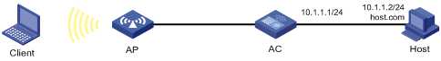
Configuration procedure
# Configure WLAN access on the AC. For more information about WLAN access configuration, see WLAN Configuration Guide. (Details not shown.)
# Configure a mapping between the host name host.com and the IP address 10.1.1.2.
<AC> system-view
[AC] ip host host.com 10.1.1.2
# Verify that the AC can use static domain name resolution to resolve the domain name host.com into the IP address 10.1.1.2.
[AC] ping host.com
Ping host.com (10.1.1.2): 56 data bytes, press CTRL_C to break
56 bytes from 10.1.1.2: icmp_seq=0 ttl=255 time=1.000 ms
56 bytes from 10.1.1.2: icmp_seq=1 ttl=255 time=1.000 ms
56 bytes from 10.1.1.2: icmp_seq=2 ttl=255 time=1.000 ms
56 bytes from 10.1.1.2: icmp_seq=3 ttl=255 time=1.000 ms
56 bytes from 10.1.1.2: icmp_seq=4 ttl=255 time=2.000 ms
--- Ping statistics for host.com ---
5 packet(s) transmitted, 5 packet(s) received, 0.0% packet loss
round-trip min/avg/max/std-dev = 1.000/1.200/2.000/0.400 ms
Dynamic domain name resolution configuration example
Network requirements
As shown in Figure 31, configure the DNS server to store the mapping between the host's domain name host and IPv4 address 3.1.1.1/16 in the com domain. Configure dynamic IPv4 DNS and the DNS suffix com on the AC so that the client can use the domain name host to access the host.
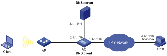
Configuration procedure
Before performing the following configuration, make sure the following requirements are met:
· The AC and the host can reach each other.
· The IP addresses of the interfaces are configured as shown in Figure 31.
1. Configure WLAN access on the AC. For more information about WLAN access configuration, see WLAN Configuration Guide. (Details not shown.)
2. Configure the DNS server:
The configuration might vary by DNS server. The following configuration is performed on a PC running Windows Server 2008 R2.
a. Select Start > Programs > Administrative Tools > DNS.
The DNS server configuration page appears, as shown in Figure 32.
b. Right-click Forward Lookup Zones, select New Zone, and then follow the wizard to create a new zone named com.
Figure 32 Creating a zone
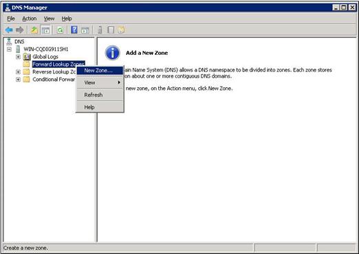
c. On the DNS server configuration page, right-click zone com and select New Host.
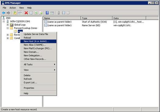
d. On the page that appears, enter the host name host and the IP address 3.1.1.1.
e. Click Add Host.
The mapping between the IP address and host name is created.
Figure 34 Adding a mapping between domain name and IP address
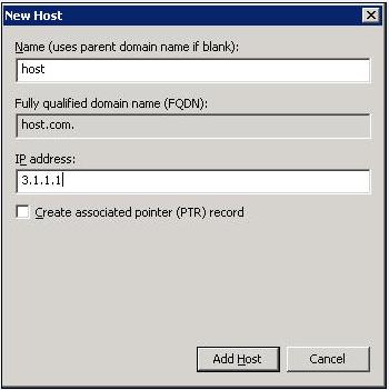
3. Configure the DNS client:
# Specify the DNS server 2.1.1.2.
<AC> system-view
[AC] dns server 2.1.1.2
# Specify com as the name suffix.
[AC] dns domain com
Verifying the configuration
# Verify that the AC can use the dynamic domain name resolution to resolve the domain name host.com into the IP address 3.1.1.1.
[AC] ping host
Ping host.com (3.1.1.1): 56 data bytes, press CTRL_C to break
56 bytes from 3.1.1.1: icmp_seq=0 ttl=255 time=1.000 ms
56 bytes from 3.1.1.1: icmp_seq=1 ttl=255 time=1.000 ms
56 bytes from 3.1.1.1: icmp_seq=2 ttl=255 time=1.000 ms
56 bytes from 3.1.1.1: icmp_seq=3 ttl=255 time=1.000 ms
56 bytes from 3.1.1.1: icmp_seq=4 ttl=255 time=2.000 ms
--- Ping statistics for host ---
5 packet(s) transmitted, 5 packet(s) received, 0.0% packet loss
round-trip min/avg/max/std-dev = 1.000/1.200/2.000/0.400 ms
DNS proxy configuration example
Network requirements
As shown in Figure 35, configure the AC as the DNS proxy to forward DNS packets between DNS clients and the DNS server at 4.1.1.1.
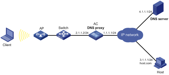
Configuration procedure
Before performing the following configuration, make sure the following requirements are met:
· The AC, the DNS server, and the host can reach one another.
· The IP addresses of the interfaces are configured as shown in Figure 35.
1. Configure WLAN access on the AC. For more information about WLAN access configuration, see WLAN Configuration Guide. (Details not shown.)
2. Configure the DNS server:
The configuration might vary by DNS server. When a PC running Windows Server 2008 R2 acts as the DNS server, see "Dynamic domain name resolution configuration example" for configuration information.
3. Configure the DNS proxy:
# Specify the DNS server 4.1.1.1.
<AC> system-view
[AC] dns server 4.1.1.1
# Enable DNS proxy.
[AC] dns proxy enable
4. Configure DNS clients and specify the DNS server 2.1.1.2 for the clients. (Details not shown.)
Verifying the configuration
# Verify that DNS proxy on the AC functions.
C:\Users\ss> ping host.com
Ping host.com (3.1.1.1): 56 data bytes, press CTRL_C to break
56 bytes from 3.1.1.1: icmp_seq=0 ttl=255 time=1.000 ms
56 bytes from 3.1.1.1: icmp_seq=1 ttl=255 time=1.000 ms
56 bytes from 3.1.1.1: icmp_seq=2 ttl=255 time=1.000 ms
56 bytes from 3.1.1.1: icmp_seq=3 ttl=255 time=1.000 ms
56 bytes from 3.1.1.1: icmp_seq=4 ttl=255 time=2.000 ms
--- Ping statistics for host.com ---
5 packet(s) transmitted, 5 packet(s) received, 0.0% packet loss
round-trip min/avg/max/std-dev = 1.000/1.200/2.000/0.400 ms
IPv6 DNS configuration examples
Static domain name resolution configuration example
Network requirements
As shown in Figure 36, the host at 1::2 has the domain name host.com. Configure static IPv6 DNS on the AC so that the client can use the easy-to-remember domain name rather than the IPv6 address to access the host.
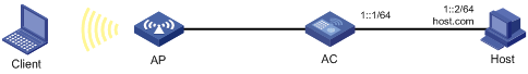
Configuration procedure
# Configure WLAN access on the AC. For more information about WLAN access configuration, see WLAN Configuration Guide. (Details not shown.)
# Configure a mapping between the host name host.com and the IPv6 address 1::2.
<AC> system-view
[AC] ipv6 host host.com 1::2
# Verify that the AC can use static domain name resolution to resolve the domain name host.com into the IPv6 address 1::2.
[AC] ping ipv6 host.com
Ping6(56 data bytes) 1::1 --> 1::2, press CTRL_C to break
56 bytes from 1::2, icmp_seq=0 hlim=128 time=1.000 ms
56 bytes from 1::2, icmp_seq=1 hlim=128 time=0.000 ms
56 bytes from 1::2, icmp_seq=2 hlim=128 time=1.000 ms
56 bytes from 1::2, icmp_seq=3 hlim=128 time=1.000 ms
56 bytes from 1::2, icmp_seq=4 hlim=128 time=0.000 ms
--- Ping6 statistics for host.com ---
5 packet(s) transmitted, 5 packet(s) received, 0.0% packet loss
round-trip min/avg/max/std-dev = 0.000/0.600/1.000/0.490 ms
Dynamic domain name resolution configuration example
Network requirements
As shown in Figure 37, configure the DNS server to store the mapping between the host's domain name host and IPv6 address 1::1/64 in the com domain. Configure dynamic IPv6 DNS and the DNS suffix com on the AC so that the client can use the domain name host to access the host.
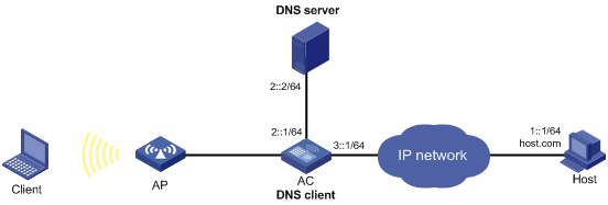
Configuration procedure
Before performing the following configuration, make sure the following requirements are met:
· The AC and the host can reach each other.
· The IPv6 addresses of the interfaces are configured as shown in Figure 37.
1. Configure WLAN access on the AC. For more information about WLAN access configuration, see WLAN Configuration Guide. (Details not shown.)
2. Configure the DNS server:
The configuration might vary by DNS server. The following configuration is performed on a PC running Windows Server 2008 R2. Make sure the DNS server supports IPv6 DNS so that the server can process IPv6 DNS packets and its interfaces can forward IPv6 packets.
a. Select Start > Programs > Administrative Tools > DNS.
The DNS server configuration page appears, as shown in Figure 38.
b. Right-click Forward Lookup Zones, select New Zone, and then follow the wizard to create a new zone named com.

c. On the DNS server configuration page, right-click zone com and select New Host.

d. On the page that appears, enter the host name host and the IPv6 address 1::1.
e. Click Add Host.
The mapping between the IPv6 address and host name is created.
Figure 40 Adding a mapping between domain name and IPv6 address
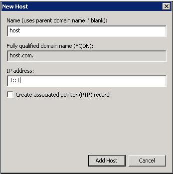
3. Configure the DNS client:
# Specify the DNS server 2::2.
<AC> system-view
[AC] ipv6 dns server 2::2
# Configure com as the DNS suffix.
[AC] dns domain com
Verifying the configuration
# Verify that the AC can use the dynamic domain name resolution to resolve the domain name host.com into the IP address 1::1.
[AC] ping ipv6 host
Ping6(56 data bytes) 3::1 --> 1::1, press CTRL_C to break
56 bytes from 1::1, icmp_seq=0 hlim=128 time=1.000 ms
56 bytes from 1::1, icmp_seq=1 hlim=128 time=0.000 ms
56 bytes from 1::1, icmp_seq=2 hlim=128 time=1.000 ms
56 bytes from 1::1, icmp_seq=3 hlim=128 time=1.000 ms
56 bytes from 1::1, icmp_seq=4 hlim=128 time=0.000 ms
--- Ping6 statistics for host ---
5 packet(s) transmitted, 5 packet(s) received, 0.0% packet loss
round-trip min/avg/max/std-dev = 0.000/0.600/1.000/0.490 ms
DNS proxy configuration example
Network requirements
As shown in Figure 41, configure the AC as the DNS proxy to forward DNS packets between DNS clients and the DNS server at 4000::1.
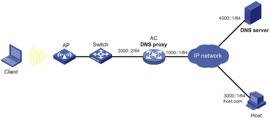
Configuration procedure
Before performing the following configuration, make sure the following requirements are met:
· The AC, the DNS server, and the host can reach to one another.
· The IPv6 addresses of the interfaces are configured as shown in Figure 41.
1. Configure WLAN access on the AC. For more information about WLAN access configuration, see WLAN Configuration Guide. (Details not shown.)
2. Configure the DNS server:
This configuration might vary by DNS server. When a PC running Windows Server 2008 R2 acts as the DNS server, see "Dynamic domain name resolution configuration example" for configuration information.
3. Configure the DNS proxy:
# Specify the DNS server 4000::1.
<AC> system-view
[AC] ipv6 dns server 4000::1
# Enable DNS proxy.
[AC] dns proxy enable
4. Configure DNS clients and specify the DNS server 2000::2 for the clients. (Details not shown.)
Verifying the configuration
# Verify that DNS proxy on the AC functions.
C:\Users\ss> ping host.com
Ping6(56 data bytes) 2000::1 --> 3000::1, press CTRL_C to break
56 bytes from 3000::1, icmp_seq=0 hlim=128 time=1.000 ms
56 bytes from 3000::1, icmp_seq=1 hlim=128 time=0.000 ms
56 bytes from 3000::1, icmp_seq=2 hlim=128 time=1.000 ms
56 bytes from 3000::1, icmp_seq=3 hlim=128 time=1.000 ms
56 bytes from 3000::1, icmp_seq=4 hlim=128 time=0.000 ms
--- Ping6 statistics for host.com ---
5 packet(s) transmitted, 5 packet(s) received, 0.0% packet loss
round-trip min/avg/max/std-dev = 0.000/0.600/1.000/0.490 ms
Troubleshooting IPv4 DNS configuration
Failure to resolve IPv4 addresses
Symptom
After enabling dynamic domain name resolution, the user cannot get the correct IP address.
Solution
To resolve the problem:
1. Use the display dns host ip command to verify that the specified domain name is in the cache.
2. If the specified domain name does not exist, check that the DNS client can communicate with the DNS server.
3. If the specified domain name is in the cache, but the IP address is incorrect, check that the DNS client has the correct IP address of the DNS server.
4. Verify that the mapping between the domain name and IP address is correct on the DNS server.
Troubleshooting IPv6 DNS configuration
Failure to resolve IPv6 addresses
Symptom
After enabling dynamic domain name resolution, the user cannot get the correct IPv6 address.
Solution
To resolve the problem:
1. Use the display dns host ipv6 command to verify that the specified domain name is in the cache.
2. If the specified domain name does not exist, check that dynamic domain name resolution is enabled, and that the DNS client can communicate with the DNS server.
3. If the specified domain name is in the cache, but the IPv6 address is incorrect, check that the DNS client has the correct IPv6 address of the DNS server.
4. Verify that the mapping between the domain name and IPv6 address is correct on the DNS server.
Configuring DDNS
Overview
DNS provides only the static mappings between domain names and IP addresses. When the IP address of a node changes, your access to the node fails.
Dynamic Domain Name System (DDNS) can dynamically update the mappings between domain names and IP addresses for DNS servers.
DDNS is supported only by IPv4 DNS, and it is used to update the mappings between domain names and IPv4 addresses.
DDNS application
As shown in Figure 42, DDNS works on the client-server model.
· DDNS client—A device that needs to update the mapping between its domain name and IP address dynamically on the DNS server when its IP address changes. An Internet user typically accesses an application layer server such as an HTTP server or an FTP server by using the server's domain name. When its IP address changes, the application layer server runs as a DDNS client. It sends a request to the DDNS server for updating the mapping between its domain name and its IP address.
· DDNS server—Informs the DNS server of latest mappings. When receiving the mapping update request from a DDNS client, the DDNS server tells the DNS server to re-map the domain name and the IP address of the DDNS client. Therefore, the Internet users can use the same domain name to access the DDNS client even if the IP address of the DDNS client has changed.
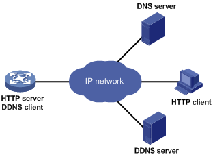
With the DDNS client configured, a device can dynamically update the latest mapping between its domain name and IP address on the DNS server through DDNS servers.
|
|
NOTE: The DDNS update process does not have a unified standard but varies by DDNS server that the DDNS client contacts. |
Feature and hardware compatibility
|
Hardware series |
Model |
DDNS compatibility |
|
WX1800H series |
WX1804H WX1810H WX1820H WX1840H |
Yes |
|
WX3800H series |
WX3820H WX3840H |
No |
|
WX5800H series |
WX5860H |
No |
DDNS client configuration task list
|
Tasks at a glance |
|
(Required.) Configuring a DDNS policy |
|
(Required.) Applying the DDNS policy to an interface |
|
(Optional.) Setting the DSCP value for outgoing DDNS packets |
Configuring a DDNS policy
A DDNS policy contains the DDNS server address, port number, login ID, password, time interval, associated SSL client policy, and update time interval. After creating a DDNS policy, you can apply it to multiple interfaces to simplify DDNS configuration.
The URL addresses configured for update requests vary by DDNS server.
Table 5 Common URL addresses
|
DDNS server |
URL addresses for DDNS update requests |
|
www.3322.org |
http://members.3322.org/dyndns/update?system=dyndns&hostname=<h>&myip=<a> |
|
DYNDNS |
http://members.dyndns.org/nic/update?system=dyndns&hostname=<h>&myip=<a> |
|
DYNS |
http://www.dyns.cx/postscript.php?host=<h>&ip=<a> |
|
ZONEEDIT |
http://dynamic.zoneedit.com/auth/dynamic.html?host=<h>&dnsto=<a> |
|
TZO |
http://cgi.tzo.com/webclient/signedon.html?TZOName=<h>IPAddress=<a> |
|
EASYDNS |
http://members.easydns.com/dyn/ez-ipupdate.php?action=edit&myip=<a>&host_id=<h> |
|
HEIPV6TB |
http://dyn.dns.he.net/nic/update?hostname=<h>&myip=<a> |
|
CHANGE-IP |
http://nic.changeip.com/nic/update?hostname=<h>&offline=1 |
|
NO-IP |
http://dynupdate.no-ip.com/nic/update?hostname=<h>&myip=<a> |
|
DHS |
http://members.dhs.org/nic/hosts?domain=dyn.dhs.org&hostname=<h>&hostscmd=edit&hostscmdstage=2&type=1&ip=<a> |
|
HP |
https://server-name/nic/update?group=group-name&myip=<a> |
|
ODS |
ods://update.ods.org |
|
GNUDIP |
gnudip://server-name |
|
PeanutHull |
oray://phservice2.oray.net |
By default, the URL address does not include a username or password. To configure the username and password, use the username command and the password command.
HP and GNUDIP are common DDNS update protocols. The server-name parameter is the domain name or IP address of the service provider's server using one of the update protocols.
The URL address for an update request can start with:
· http://—The HTTP-based DDNS server.
· https://—The HTTPS-based DDNS server.
· ods://—The TCP-based ODS server.
· gnudip://—The TCP-based GNUDIP server.
· oray://—The TCP-based DDNS server.
The domain names of DDNS servers are members.3322.org and phservice2.oray.net. The domain names of PeanutHull DDNS servers can be phservice2.oray.net, phddns60.oray.net, client.oray.net, ph031.oray.net, and so on. Determine the domain name in the URL according to the actual situation.
The port number in the URL address is optional. If no port is specified, the system uses the default port numbers: port 80 for HTTP, port 443 for HTTPS, and port 6060 for PeanutHull DDNS server.
The system automatically performs the following tasks:
· Fills <h> with the FQDN upon a DDNS policy application to the interface.
· Fills <a> with the primary IP address of the interface to which the DDNS policy is applied.
You can also manually specify an FQDN and an IP address in <h> and <a>. In this case, the FQDN specified upon the DDNS policy application does not take effect. You are not encouraged to manually change the <h> and <a> because your configuration might be incorrect. For more information about applying DDNS policies, see "Applying the DDNS policy to an interface."
No FQDN or IP address can be specified in the URL address for update requests sent to the PeanutHull DDNS server. You can specify the FQDN when applying the DDNS policy to an interface. The IP address is the primary IP address of the interface to which the DDNS policy is applied.
|
|
TIP: The FQDN is the only identification of a node in the network. An FQDN consists of a local host name and a parent domain name and can be translated into an IP address. |
Configuration prerequisites
Visit the website of a DDNS service provider, register an account, and apply for a domain name for the DDNS client. When the DDNS client updates the mapping between the domain name and the IP address through the DDNS server, the DDNS server checks the following:
· Whether the account information is correct.
· Whether the domain name to be updated belongs to the account.
Configuration procedure
To configure a DDNS policy:
|
Step |
Command |
Remarks |
|
1. Enter system view. |
system-view |
N/A |
|
2. Create a DDNS policy and enter its view. |
ddns policy policy-name |
By default, no DDNS policy is created. |
|
3. Specify a URL address for DDNS update requests. |
url request-url |
By default, no URL address is specified for DDNS update requests. |
|
4. Specify the username for logging in to the DDNS server. |
username username |
By default, no username is specified. |
|
5. Specify the password for logging in to the DDNS server. |
password { cipher | simple } password |
By default, no password is specified. |
|
6. (Optional.) Specify the parameter transmission method for sending DDNS update requests to HTTP/HTTPS-based DDNS servers. |
method { http-get | http-post } |
By default, http-get is used. Use the method http-post command to specify the POST method for DDNS update with a DHS server. |
|
7. (Optional.) Associate an SSL client policy with the DDNS policy. |
ssl-client-policy policy-name |
By default, no SSL client policy is associated with the DDNS policy. This step is only effective and a must for HTTP-based DDNS update requests. For SSL client policy configuration, see Security Configuration Guide. |
|
8. (Optional.) Specify the interval for sending update requests. |
interval days [ hours [ minutes ] ] |
By default, the time interval is one hour. |
Applying the DDNS policy to an interface
After you apply the DDNS policy to an interface and specify the FQDN for update, the DDNS client sends requests to the DDNS server to update the mapping between the domain name and the primary IP address of the interface at the specified interval.
Before you apply a DDNS policy to an interface, complete the following tasks:
· Specify the primary IP address of the interface and make sure the DDNS server and the interface can reach each other.
· Configure static or dynamic domain name resolution to translate the domain name of the DDNS server into the IPv4 address. For more information, see "Configuring the IPv4 DNS client."
To apply the DDNS policy to an interface:
|
Step |
Command |
Remarks |
|
1. Enter system view. |
system-view |
N/A |
|
2. Enter interface view. |
interface interface-type interface-number |
N/A |
|
3. Apply the DDNS policy to the interface to update the mapping between the specified FQDN and the primary IP address of the interface, and enable DDNS update. |
ddns apply policy policy-name [ fqdn domain-name ] |
By default, no DDNS policy is applied to the interface, no FQDN is specified for update, and DDNS update is disabled. The fqdn domain-name option must be specified for all DDNS servers except the PeanutHull DDNS server. |
|
|
NOTE: If no FQDN is specified for the PeanutHull DDNS server, the DDNS server updates all domain names of the DDNS client account. If an FQDN is specified, the DDNS server updates only the mapping between the specified FQDN and the primary IP address. |
Setting the DSCP value for outgoing DDNS packets
The DSCP value of a packet specifies the priority level of the packet and affects the transmission priority of the packet. A bigger DSCP value represents a higher priority.
To set the DSCP value for outgoing DDNS packets:
|
Step |
Command |
Remarks |
|
1. Enter system view. |
system-view |
N/A |
|
2. Set the DSCP value for outgoing DDNS packets. |
ddns dscp dscp-value |
By default, the DSCP value for outgoing DDNS packets is 0. |
Displaying DDNS
Execute display commands in any view.
|
Task |
Command |
|
Display information about the DDNS policy. |
display ddns policy [ policy-name ] |
Configuring NAT
Overview
Network Address Translation (NAT) translates an IP address in the IP packet header to another IP address. Typically, NAT is configured on gateways to enable private hosts to access external networks and external hosts to access private network resources such as a Web server.
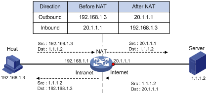
As shown in Figure 43:
1. Upon receiving a request from the host to the server, NAT translates the private source address 192.168.1.3 to the public address 20.1.1.1 and forwards the NATed packet. NAT adds a mapping for the two addresses to its NAT table.
2. Upon receiving a response from the server, NAT translates the destination public address to the private address, and forwards the packet to the host.
The NAT operation is transparent to the terminals. NAT hides the private network from the external users and shows that the IP address of the internal host is 20.1.1.1.
Terminology
The following describes NAT terminologies:
· NAT device—A device configured with NAT.
· NAT interface—An interface enabled with NAT.
· NAT entry—Stores the mapping between a private address and a public address. For more information, see "NAT entries."
· Easy IP—Uses the IP address of an interface as the public address. The IP address of the interface is obtained through DHCP or PPPoE.
NAT types
Traditional NAT
Traditional NAT applies to the interface connected to the public network. It translates the source IP addresses of outgoing packets and destination IP addresses of incoming packets.
Bidirectional NAT
NAT translates the source and destination IP addresses of incoming packets on the receiving interface and outgoing packets on the sending interface.
Bidirectional NAT is applied when source and destination addresses overlap.
Twice NAT
Twice NAT translates the destination IP address on the receiving interface, and the source IP address on the sending interface. The receiving and sending interfaces are both NAT interfaces.
Twice NAT allows internal networks with overlapping addresses to access each other.
NAT hairpin
NAT hairpin allows internal hosts to access each other through NAT. The source and destination IP address of the packets are translated on the interface connected to the internal network.
NAT hairpin includes P2P and C/S modes:
· P2P—Allows internal hosts to access each other through NAT.
· C/S—Allows internal hosts to access internal servers through NAT.
NAT control
You can use ACLs to implement NAT control. The match criteria in the ACLs include the source IP address, source port number, destination IP address, destination port number, and transport layer protocol. Only packets permitted by an ACL are processed by NAT.
Command and hardware compatibility
The WX1800H series access controllers do not support the slot keyword or the slot-number argument.
NAT implementations
Static NAT
Static NAT creates a fixed mapping between a private address and a public address. Static NAT allows bidirectional connection initiation, both from and to the internal host. Static NAT applies to regular communications.
Dynamic NAT
Dynamic NAT uses an address pool to translate addresses. Dynamic NAT includes Not Port Address Translation (NO-PAT) and Port Address Translation (PAT) modes.
NO-PAT
NO-PAT translates a private address to a public address. The public address cannot be used by another internal host until it is released.
NO-PAT supports all IP packets.
PAT
PAT translates multiple private addresses to a single public address by mapping the private address and source port to the public address and a unique port. PAT supports TCP and UDP packets, and ICMP request packets.
Figure 44 PAT operation
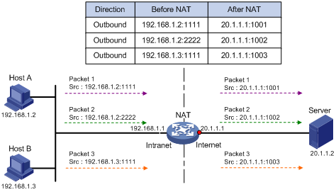
As shown in Figure 44, PAT translates the source IP addresses of the three packets to the same public address and translates their port numbers to different port numbers. Upon receiving a response, PAT translates the destination address and port number of the response, and forwards it to the target host.
PAT supports the following mappings:
· Endpoint-Independent Mapping (EIM)—Uses the same IP and port mapping (EIM entry) for packets from the same source IP and port to any destinations. EIM allows external hosts to initiate connections to the translated IP addresses and ports of internal hosts. It allows internal hosts behind different NAT gateways to access each other.
· Address and Port-Dependent Mapping (ADPM)—Uses different IP and port mappings for packets from the same source IP and port to different destination IP addresses and ports. APDM allows an external host to initiate connections to an internal host only under the condition that the internal host has previously accessed the external host. It is secure, but it does not allow internal hosts behind different NAT gateways to access each other.
NAT Server
The NAT Server feature maps a public address and port number to the private IP address and port number of an internal server. This feature allows servers in the private network to provide services for external users.
Figure 45 NAT Server operation
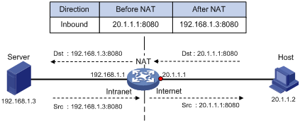
Figure 45 displays how NAT Server works:
1. Upon receiving a request from the host, NAT translates the public destination IP address and port number to the private IP address and port number of the internal server.
2. Upon receiving a response from the server, NAT translates the private source IP address and port number to the public IP address and port number.
NAT444
NAT444 provides carrier-grade NAT. It is a preferred solution for carriers to mitigate IPv4 address exhaustion. It introduces a second layer of NAT on the carrier side, with few changes on the customer side and the application server side.
NAT444 provides port block-based PAT translation. It maps multiple private IP addresses to one public IP address and uses a different port block for each private IP address. For example, the private IP address 10.1.1.1 of an internal host is mapped to the public IP address 202.1.1.1 and port block 10001 to 10256. When the internal host accesses public hosts, the source IP address 10.1.1.1 is translated to 202.1.1.1, and the source ports are translated to ports in the port block 10001 to 10256.
NAT444 includes static NAT444 and dynamic NAT444.
As shown in Figure 46, the NAT444 architecture includes the following entities:
· CPE—Provides NAT services on the customer side.
· BRAS—Provides Internet access services.
· NAT444 gateway—Provides carrier-grade NAT services.
· AAA server—Cooperates with BRAS to provide user authentication, authorization, and accounting services.
· Log server—Records user access logs and responds to queries for user access information.
The AAA server authenticates the internal users and starts accounting after users pass the authentication. The BRAS device assigns private IP addresses to authenticated users. When a user accesses the external network, the NAT444 gateway assigns the user a public IP address and port block, and sends the mapping to the log server. The next time the user accesses the external network, the NAT444 gateway assigns a new mapping if the former mapping ages out and sends the new mapping to the log server. The log server uses the mappings for user tracing.
Figure 46 NAT444 application diagram
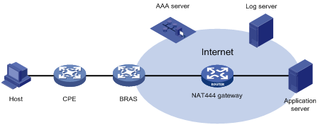
Static NAT444
The NAT444 gateway computes a static NAT444 mapping before address translation. The mapping is between a private IP address and a public IP address with a port block.
The NAT444 gateway uses private IP addresses, public IP addresses, a port range, and a port block size to compute static mappings:
1. Divides the port range by the port block size to get the number of available port blocks for each public IP address.
This value is the base number for mapping.
2. Sorts the port blocks in ascending order of the start port number in each block.
3. Sorts the private IP addresses and the public IP addresses separately in ascending order.
4. Maps the first base number of private IP addresses to the first public IP address and its port blocks in ascending order.
For example, the number of available port blocks of each public IP address is m. The first m private IP addresses are mapped to the first public IP address and the m port blocks in ascending order. The next m private IP addresses are mapped to the second IP address and the m port blocks in ascending order. The other static NAT444 mappings are created by analogy.
Dynamic NAT444
Dynamic NAT444 works as follows:
1. Creates a mapping from the internal host's private IP address to a public IP address and a port block when the host initiates a connection to the public network.
2. Translates the private IP address to the public IP address, and the source ports to ports in the selected port block for subsequent connections from the private IP address.
3. Withdraws the port block and deletes the dynamic NAT444 mapping when all connections from the private IP address are disconnected.
Dynamic NAT444 uses ACLs to implement translation control. It processes only packets that match an ACL permit rule.
Dynamic NAT444 supports port block extending. If the ports in the port block for a private address are all occupied, dynamic NAT444 translates the source port to a port in an extended port block.
NAT444 gateway unified with BRAS device
NAT444 gateway and BRAS device unification is supported only for PPP users.
To unify the NAT444 gateway and BRAS device, specify the user address type in the ISP domain. Supported user address types include private IPv4 address and private-DS address.
As shown in Figure 47, the NAT444 gateway and BRAS device function as follows after the unification:
1. After a user of the specified address type passes authentication and obtains a private address, NAT444 immediately assigns a public IP address and a port block to the user.
2. NAT444 sends the NAT444 mapping to the BRAS.
3. The BRAS records the mapping and reports it to the AAA server.
Compared to the separation of BRAS and NAT444, the unification provides the following functions:
· If the NAT444 resources have been used up, the BRAS logs off the user, which ensures accurate accounting on the AAA server.
· The AAA server maintains one mapping for each online user until the user goes offline. This solution implements user tracing without requiring an extra log server.
Figure 47 NAT444 gateway unified with BRAS device
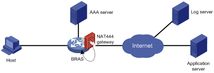
|
|
NOTE: If the NAT444 configuration changes, NAT444 mappings for online users also change. The change cannot be synchronized to the AAA server, affecting user tracing accuracy. H3C recommends that you log off the users immediately after you change the NAT444 configuration. When the users come online, NAT444 creates new mappings for them. |
NAT entries
NAT session entry
NAT creates a NAT session entry for a session and creates an address mapping for the first packet in the session.
A NAT session entry contains extended NAT information, such as interface and translation method. Subsequent packets of the session are translated by using this entry.
The session management module maintains the updating and aging of NAT session entries. For information about session management, see Security Configuration Guide.
EIM entry
An EIM entry maps a private address/port to a public address/port. The same EIM entry applies to subsequent connections originating from the same source IP and port.
An EIM entry ages out after all related NAT session entries age out.
NO-PAT entry
A NO-PAT entry maps a private address to a public address. The same mapping applies to subsequent connections originating from the same source IP.
A NO-PAT entry can also be created during the ALG process for NAT. For information about NAT with ALG, see "NAT with ALG."
A NO-PAT entry ages out after all related NAT session entries age out.
NAT444 entry
A NAT444 entry maps a private IP address to a public IP address and a port block.
NAT444 entries include static and dynamic NAT444 mappings. For information about these mappings, see "Static NAT444" and "Dynamic NAT444."
Using NAT with other features
NAT with DNS mapping
NAT with DNS mapping allows an internal host to access an internal server on the same private network by using the domain name of the internal server when the DNS server is on the public network.
NAT with DNS mapping must operate with the NAT Server feature.
Figure 48 NAT with DNS mapping
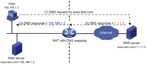
As shown in Figure 48, NAT with DNS mapping works as follows:
1. The host sends a DNS request containing the domain name of the internal Web server.
2. Upon receiving the DNS response, the NAT device performs a DNS mapping lookup by using the domain name in the response. A DNS mapping for NAT maps the domain name to the public IP address, public port number, and the protocol type for the internal server.
3. If a match is found, the NAT continues to compare the public address, public port number, and the protocol type with the NAT Server configuration. The NAT Server configuration maps the public IP address and port number to the private IP address and port number for the internal server.
4. If a match is found, NAT translates the public IP address in the response into the private IP address of the Web server.
5. The internal host receives the DNS response, and obtains the private IP address of the Web server.
DNS mapping can also be used by DNS ALG. The DNS reply from the external DNS server contains only the domain name and public IP address of the internal server in the payload. The NAT interface might have multiple internal servers configured with the same public IP address but different private IP addresses. DNS ALG might find an incorrect internal server by using only the public IP address. If a DNS mapping is configured, DNS ALG can obtain the public IP address, public port number, and protocol type of the internal server by using the domain name. Then it can find the correct internal server by using the public IP address, public port number, and protocol type of the internal server.
NAT with ALG
NAT with ALG translates address or port information in the application layer payloads to ensure connection establishment.
For example, an FTP application includes a data connection and a control connection. The IP address and port number for the data connection depend on the payload information of the control connection. This requires NAT with ALG to translate the address and port information for data connection establishment.
NAT configuration task list
|
Tasks at a glance |
Remarks |
|
Perform one or more of the following tasks: |
If you perform all the tasks on an interface, the NAT rules are sorted in the following order: · NAT Server. · Static NAT. · Static NAT444. · Dynamic NAT and dynamic NAT444. |
|
(Optional.) Modifying the priority of a NAT rule |
N/A |
|
(Optional.) Configuring NAT with DNS mapping |
N/A |
|
(Optional.) Configuring NAT hairpin |
N/A |
|
(Optional.) Configuring NAT with ALG |
N/A |
|
(Optional.) Configuring NAT logging |
N/A |
|
(Optional.) Enabling sending ICMP error messages for NAT failures |
N/A |
Configuring static NAT
Static NAT includes one-to-one static NAT and net-to-net static NAT for outbound and inbound translation. Do not configure inbound static NAT alone. Typically, inbound static NAT functions with outbound dynamic NAT, NAT Server, or outbound static NAT to implement bidirectional NAT.
Configuration prerequisites
Perform the following tasks before configuring static NAT:
· Configure an ACL to identify the IP addresses to be translated. The match criteria include the source IP address, source port number, destination IP address, destination port number, and transport layer protocol. For more information about ACLs, see ACL and QoS Configuration Guide.
· Manually add a route for inbound static NAT. Use local-ip or local-network as the destination address, and use global-ip, an address in global-network, or the next hop directly connected to the output interface as the next hop.
Configuring outbound one-to-one static NAT
For address translation from a private IP address to a public IP address, configure outbound one-to-one static NAT on the interface connected to the external network.
· When the source IP address of a packet from the private network matches the local-ip, the source IP address is translated into the global-ip.
· When the destination IP address of a packet from the public network matches the global-ip, the destination IP address is translated into the local-ip.
To configure outbound one-to-one static NAT:
|
Step |
Command |
Remarks |
|
1. Enter system view. |
system-view |
N/A |
|
2. Configure a one-to-one mapping for outbound static NAT. |
nat static outbound local-ip [ acl { acl-number | name acl-name } [ reversible ] ] global-ip [ rule rule-name ] [ priority priority ] [ disable ] |
By default, no mappings exist. If you specify the acl keyword, NAT processes only packets matching the permit rule in the ACL. |
|
3. Enter interface view. |
interface interface-type interface-number |
N/A |
|
4. Enable static NAT on the interface. |
nat static enable |
By default, static NAT is disabled. |
Configuring outbound net-to-net static NAT
For address translation from a private network to a public network, configure outbound net-to-net static NAT on the interface connected to the external network.
· When the source IP address of a packet from the private network matches the private address range, the source IP address is translated into a public address in the public address range.
· When the destination IP address of a packet from the public network matches the public address range, the destination IP address is translated into a private address in the private address range.
To configure outbound net-to-net static NAT:
|
Step |
Command |
Remarks |
|
1. Enter system view. |
system-view |
N/A |
|
2. Configure a net-to-net mapping for outbound static NAT. |
nat static outbound net-to-net local-start-address local-end-address [ acl { acl-number | name acl-name } [ reversible ] ] global global-network { mask-length | mask } [ rule rule-name ] [ priority priority ] [ disable ] |
By default, no mappings exist. If you specify the acl keyword, NAT processes only packets permitted by the ACL. |
|
3. Enter interface view. |
interface interface-type interface-number |
N/A |
|
4. Enable static NAT on the interface. |
nat static enable |
By default, static NAT is disabled. |
Configuring inbound one-to-one static NAT
For address translation from a public IP address to a private IP address, configure inbound one-to-one static NAT.
· When the source IP address of a packet from the public network to the private network matches the global-ip, the source IP address is translated into the local-ip.
· When the destination IP address of a packet from the private network to the public network matches the local-ip, the destination IP address is translated into the global-ip.
To configure inbound one-to-one static NAT:
|
Step |
Command |
Remarks |
|
1. Enter system view. |
system-view |
N/A |
|
2. Configure a one-to-one mapping for inbound static NAT. |
nat static inbound global-ip [ acl { acl-number | name acl-name } [ reversible ] ] local-ip [ rule rule-name ] [ priority priority ] [ disable ] |
By default, no mappings exist. If you specify the acl keyword, NAT processes only packets permitted by the ACL. |
|
3. Enter interface view. |
interface interface-type interface-number |
N/A |
|
4. Enable static NAT on the interface. |
nat static enable |
By default, static NAT is disabled. |
Configuring inbound net-to-net static NAT
For address translation from a public network to a private network, configure inbound net-to-net static NAT.
· When the source IP address of a packet from the public network matches the public address range, the source IP address is translated into a private address in the private address range.
· When the destination IP address of a packet from the private network matches the private address range, the destination IP address is translated into a public address in the public address range.
To configure inbound net-to-net static NAT:
|
Step |
Command |
Remarks |
|
1. Enter system view. |
system-view |
N/A |
|
2. Configure a net-to-net mapping for inbound static NAT. |
nat static inbound net-to-net global-start-address global-end-address [ acl { acl-number | name acl-name } [ reversible ] ] local local-network { mask-length | mask } [ rule rule-name ] [ priority priority ] [ disable ] |
By default, no mappings exist. If you specify the acl keyword, NAT processes only packets permitted by the ACL. |
|
3. Enter interface view. |
interface interface-type interface-number |
N/A |
|
4. Enable static NAT on the interface. |
nat static enable |
By default, static NAT is disabled. |
Configuring dynamic NAT
Dynamic NAT translates a group of private IP addresses into a smaller number of public addresses. You can specify an address group (or the IP address of an interface) and an ACL to implement dynamic NAT.
Configuration restrictions and guidelines
When you configure dynamic NAT, follow these restrictions and guidelines:
· You can configure multiple inbound or outbound dynamic NAT rules.
· A NAT rule with an ACL takes precedence over a rule without any ACL.
· If two ACL-based dynamic NAT rules are configured, the rule with the higher ACL number has higher priority.
Configuration prerequisites
Perform the following tasks before configuring dynamic NAT:
· Configure an ACL to identify the IP addresses to be translated. The match criteria include the source IP address, source port number, destination IP address, destination port number, and transport layer protocol. For more information about ACLs, see ACL and QoS Configuration Guide.
· Determine whether to enable the Easy IP feature. If you use the IP address of an interface as the public address, you are configuring Easy IP.
· Determine a public IP address pool for address translation.
· Determine whether to translate port numbers. Use NO-PAT to translate only IP addresses and PAT to translate both IP addresses and port numbers.
Configuring outbound dynamic NAT
To translate private IP addresses into public IP addresses, configure outbound dynamic NAT on the interface connected to the external network.
The source IP addresses of the outgoing packets that match the ACL permit rule are translated into IP addresses in the address group.
The reversible keyword enables the device to perform the following operations:
· Compare the destination IP address in the first packet from the public network with existing NO-PAT entries.
· Translate the destination address into the private address in a matching NO-PAT entry.
To configure outbound dynamic NAT:
|
Step |
Command |
Remarks |
|
1. Enter system view. |
system-view |
N/A |
|
2. Configure an address group and enter its view. |
nat address-group group-number [ name group-name ] |
By default, no address group exists. |
|
3. Add an address range to the address group. |
address start-address end-address |
By default, no address range exists. You can add multiple address ranges to an address group. The address ranges must not overlap. |
|
4. Return to system view. |
quit |
N/A |
|
5. Enter interface view. |
interface interface-type interface-number |
N/A |
|
6. Configure outbound dynamic NAT. |
· Configure NO-PAT: · Configure PAT: |
By default, outbound dynamic NAT is not configured. You can configure multiple outbound dynamic NAT rules on an interface. |
|
7. Return to system view. |
quit |
N/A |
|
8. (Optional.) Configure a PAT mapping mode. |
nat mapping-behavior endpoint-independent [ acl { acl-number | name acl-name } ] |
The default mapping mode is Address and Port-Dependent Mapping. This command takes effect only on outbound dynamic NAT for PAT. |
Configuring inbound dynamic NAT
Inbound dynamic NAT enables translation from public IP addresses to private IP addresses. Do not configure it alone. Typically, inbound dynamic NAT functions with outbound dynamic NAT, NAT Server, or outbound static NAT to implement bidirectional NAT.
The source IP address of a received packet that is permitted by the ACL is translated into a public address in the address group.
The add-route keyword enables the device to automatically add a route destined for the private address when an inbound dynamic NAT rule is matched. The output interface is the NAT interface, and the next hop is the source address before translation. If you do not specify this keyword, you must manually add the route. H3C recommends that you manually create a route because it takes time to automatically add routes.
The reversible keyword enables the device to perform the following operations:
· Compare the destination IP address in the first packet from the private network with existing NO-PAT entries.
· Translate the destination address into the public address in a matching NO-PAT entry.
Inbound dynamic NAT does not support Easy IP.
To configure inbound dynamic NAT:
|
Step |
Command |
Remarks |
|
1. Enter system view. |
system-view |
N/A |
|
2. Configure an address group and enter its view. |
nat address-group group-number [ name group-name ] |
By default, no address group exists. |
|
3. Add an address range to the address group. |
address start-address end-address |
By default, no address range exists. You can add multiple address ranges to an address group. The address ranges must not overlap. |
|
4. Return to system view. |
quit |
N/A |
|
5. Enter interface view. |
interface interface-type interface-number |
N/A |
|
6. Configure inbound dynamic NAT. |
nat inbound { acl-number | name acl-name } address-group { group-number | name group-name } [ no-pat [ reversible ] [ add-route ] ] [ rule rule-name ] [ priority priority ] [ disable ] [ description text ] |
By default, inbound dynamic NAT is not configured. You can configure multiple inbound dynamic NAT rules on an interface. |
Configuring NAT Server
To configure NAT Server, map a public IP address and port number to the private IP address and port number of an internal server on the interface connected to the external network.
If you specify the acl keyword for the common NAT Server or load sharing NAT Server configuration, only packets matching the ACL permit rule are translated. The match criteria include the source IP address, source port number, destination IP address, destination port number, and transport layer protocol.
Configuring common NAT Server
|
Step |
Command |
Remarks |
|
1. Enter system view. |
system-view |
N/A |
|
2. Enter interface view. |
interface interface-type interface-number |
N/A |
|
3. Configure one or more common NAT Server mappings. |
· A single public address with a single or no public port: · A single public address with consecutive public ports: · Consecutive public addresses with a single or no public port: · Consecutive public addresses with a single public port: |
By default, no NAT Server mapping exists. You can configure multiple NAT Server mappings on an interface. |
Configuring load sharing NAT Server
You can add multiple internal servers to an internal server group so that these servers provide the same service for external hosts. The NAT device chooses one internal server based on the weight and number of connections of the servers to respond to a request from an external host to the public address of the internal server group.
To configure load sharing NAT Server:
|
Step |
Command |
Remarks |
|
1. Enter system view. |
system-view |
N/A |
|
2. Configure a NAT Server group and enter its view. |
nat server-group group-number |
By default, no NAT Server group exists. |
|
3. Add an internal server into the group. |
inside ip inside-ip port port-number [ weight weight-value ] |
By default, no internal server is in the group. You can add multiple internal servers to a group. |
|
4. Return to system view. |
quit |
N/A |
|
5. Enter interface view. |
interface interface-type interface-number |
N/A |
|
6. Configure load sharing NAT Server. |
nat server protocol pro-type global { { global-address | current-interface | interface interface-type interface-number } { global-port | global-port1 global-port2 } | global-address1 global-address2 global-port } inside server-group group-number [ acl { acl-number | name acl-name } ] [ rule rule-name ] [ disable ] |
By default, no load sharing NAT Server mapping exists. You can configure multiple load sharing NAT Server mappings on an interface. |
Configuring ACL-based NAT Server
ACL-based NAT Server is an extension of common NAT Server. Common NAT Server maps the private IP address of the internal server to a single public IP address. ACL-based NAT Server maps the private IP address of the internal server to a set of public IP addresses defined by an ACL. If the destination address of a packet matches a permit rule, the destination address is translated into the private IP address of the internal server.
To configure ACL-based NAT Server:
|
Step |
Command |
Remarks |
|
1. Enter system view. |
system-view |
N/A |
|
2. Enter interface view. |
interface interface-type interface-number |
N/A |
|
3. Configure ACL-based NAT Server. |
nat server global { global-acl-number | name global-acl-name } inside local-address [ local-port ] [ rule rule-name ] [ priority priority ] [ disable ] |
By default, no ACL-based NAT Server mapping exists. You can configure multiple NAT Server mappings on an interface. |
Configuring NAT444
NAT444 provides outbound address translation, and it is configured on the interface connected to the public network.
Configuring static NAT444
Static NAT444 is applicable when the private IP addresses are fixed.
To configure static NAT444:
|
Step |
Command |
Remarks |
|
1. Enter system view. |
system-view |
N/A |
|
2. Create a NAT port block group, and enter its view. |
nat port-block-group group-number |
By default, no port block group exists. |
|
3. Add a private IP address range to the port block group. |
local-ip-address start-address end-address |
By default, no private IP address range exists in the port block group. You can add multiple private IP address ranges to one port block group, but they cannot overlap. |
|
4. Add a public IP address range to the port block group. |
global-ip-pool start-address end-address |
By default, no public IP address range exists in the port block group. You can add multiple public IP address ranges to one port block group, but they cannot overlap. |
|
5. Configure the port range for the public IP addresses. |
port-range start-port-number end-port-number |
By default, the port range is 1 to 65535. |
|
6. Set the port block size. |
block-size block-size |
By default, the port block size is 256. |
|
7. Return to system view. |
quit |
N/A |
|
8. Enter interface view. |
interface interface-type interface-number |
N/A |
|
9. Apply the port block group to the outbound direction of the interface. |
nat outbound port-block-group group-number [ rule rule-name ] |
By default, no port block group is applied to the interface. You can apply multiple port block groups to one interface. |
|
10. Return to system view. |
quit |
N/A |
|
11. (Optional.) Configure a PAT mapping mode. |
nat mapping-behavior endpoint-independent [ acl { acl-number | name acl-name } ] |
The default mapping mode is Address and Port-Dependent Mapping. |
Configuring dynamic NAT444
Dynamic NAT444 is applicable when the private IP addresses are not fixed.
To configure dynamic NAT444:
|
Step |
Command |
Remarks |
|
1. Enter system view. |
system-view |
N/A |
|
2. Create a NAT address group, and enter its view. |
nat address-group group-number [ name group-name ] |
By default, no NAT address group exists. |
|
3. Add a public IP address range to the NAT address group. |
address start-address end-address |
By default, no public IP address range exists in the NAT address group. You can add multiple public IP address ranges to an address group, but they cannot overlap. |
|
4. Configure the port range for the public IP addresses. |
port-range start-port-number end-port-number |
By default, the port range is 1 to 65535. The configuration takes effect only on PAT translation mode. |
|
5. Configure port block parameters. |
port-block block-size block-size [ extended-block-number extended-block-number ] |
By default, no port block parameter exists. The configuration takes effect only on PAT translation mode. |
|
6. Return to system view. |
quit |
N/A |
|
7. Enter interface view. |
interface interface-type interface-number |
N/A |
|
8. Configure PAT for outbound dynamic NAT. |
nat outbound [ acl-number | name acl-name ] [ address-group group-number | name group-name } ] [ port-preserved ] [ rule rule-name ] [ priority priority ] |
By default, outbound dynamic NAT is not configured. The port-preserved keyword does not take effect on dynamic NAT444. |
|
9. Return to system view. |
quit |
N/A |
|
10. (Optional.) Configure a PAT mapping mode. |
nat mapping-behavior endpoint-independent [ acl { acl-number | name acl-name } ] |
The default mapping mode is Address and Port-Dependent Mapping. |
Enabling global mapping sharing for dynamic NAT444
When multiple interfaces have dynamic NAT444 configured, the interfaces might create different NAT444 mappings for packets from the same IP address. You can perform this task to configure the interfaces to share the same NAT444 mapping for translating packets from the same IP address.
To enable global mapping sharing for dynamic NAT444:
|
Step |
Command |
Remarks |
|
1. Enter system view. |
system-view |
N/A |
|
2. Enable global mapping sharing for dynamic NAT444. |
nat port-block global-share enable |
By default, global mapping sharing is disabled for dynamic NAT444. |
Modifying the priority of a NAT rule
Modifying the priority of an outbound dynamic NAT rule
To modify the priority of an outbound dynamic NAT rule:
|
Step |
Command |
Remarks |
|
1. Enter system view. |
system-view |
N/A |
|
2. Enter interface view. |
interface interface-type interface-number |
N/A |
|
3. Modify the priority of an outbound dynamic NAT rule. |
nat outbound rule move nat-rule-name1 { after | before } nat-rule-name2 |
This command takes effect only on an outbound dynamic NAT rule that has a name. |
Modifying the priority of an inbound dynamic NAT rule
To modify the priority of an inbound dynamic NAT rule:
|
Step |
Command |
Remarks |
|
1. Enter system view. |
system-view |
N/A |
|
2. Enter interface view. |
interface interface-type interface-number |
N/A |
|
3. Modify the priority of an inbound dynamic NAT rule. |
nat inbound rule move nat-rule-name1 { after | before } nat-rule-name2 |
This command takes effect only on an inbound dynamic NAT rule that has a name. |
Modifying the priority of a one-to-one static inbound NAT rule
To modify the priority of a one-to-one static inbound NAT rule:
|
Step |
Command |
Remarks |
|
1. Enter system view. |
system-view |
N/A |
|
2. Modify the priority of a one-to-one static inbound NAT rule. |
nat static inbound rule move nat-rule-name1 { after | before } nat-rule-name2 |
This command takes effect only on a one-to-one static inbound NAT rule that has a name. |
Modifying the priority of a one-to-one static outbound NAT rule
To modify the priority of a one-to-one static outbound NAT rule:
|
Step |
Command |
Remarks |
|
1. Enter system view. |
system-view |
N/A |
|
2. Modify the priority of a one-to-one static outbound NAT rule. |
nat static outbound rule move nat-rule-name1 { after | before } nat-rule-name2 |
This command takes effect only on a one-to-one static outbound NAT rule that has a name. |
Modifying the priority of an ACL-based NAT server rule
To modify the priority of an ACL-based NAT server rule:
|
Step |
Command |
Remarks |
|
1. Enter system view. |
system-view |
N/A |
|
2. Enter interface view. |
interface interface-type interface-number |
N/A |
|
3. Modify the priority of an ACL-based NAT server rule. |
nat server rule move nat-rule-name1 { after | before } nat-rule-name2 |
This command takes effect only on an ACL-based NAT server rule that has a name. |
Configuring NAT with DNS mapping
NAT with DNS mapping must operate together with NAT Server and NAT with ALG.
To configure NAT with DNS mapping:
|
Step |
Command |
Remarks |
|
1. Enter system view. |
system-view |
N/A |
|
2. Configure a DNS mapping for NAT. |
By default, no DNS mapping for NAT exists. You can configure multiple DNS mappings for NAT. |
Configuring NAT hairpin
Configure NAT hairpin on the interface connected to the internal network. NAT hairpin supports P2P mode and C/S mode.
· To configure the P2P mode, you must configure outbound PAT on the interface connected to the external network and enable the EIM mapping mode. Internal hosts first register their public addresses to an external server. Then, the hosts communicate with each other by using the registered IP addresses.
· In C/S mode, the destination IP address of the packet going to the internal server is translated by matching the NAT Server configuration. The source IP address is translated by matching the outbound dynamic or static NAT entries.
NAT hairpin typically operates with NAT Server, outbound dynamic NAT, or outbound static NAT. Otherwise, NAT hairpin cannot function correctly.
To configure NAT hairpin:
|
Step |
Command |
Remarks |
|
1. Enter system view. |
system-view |
N/A |
|
2. Enter interface view. |
interface interface-type interface-number |
N/A |
|
3. Enable NAT hairpin. |
nat hairpin enable |
By default, NAT hairpin is disabled. |
Configuring NAT with ALG
Configure NAT with ALG for a protocol to translate the IP addresses and port numbers in the payloads for application layer packets.
To configure NAT with ALG:
|
Step |
Command |
Remarks |
|
1. Enter system view. |
system-view |
N/A |
|
2. Configure NAT with ALG for a protocol or all protocols. |
nat alg { all | dns | ftp | h323 | icmp-error | ils | mgcp | nbt | pptp | rsh | rtsp | sccp | sip | sqlnet | tftp | xdmcp } |
By default, NAT with ALG is enabled for DNS, FTP, ICMP error messages, RTSP, and PPTP, and is disabled for the other supported protocols. |
Configuring NAT logging
Configuring NAT session logging
NAT session logging records NAT session information, including translation information and access information.
A NAT device generates NAT session logs for the following events:
· NAT session establishment.
· NAT session removal. This event occurs when you add a configuration with a higher priority, remove a configuration, change ACLs, when a NAT session ages out, or when you manually delete a NAT session.
· Active NAT session logging.
To enable NAT session logging:
|
Step |
Command |
Remarks |
|
|
1. Enter system view. |
system-view |
N/A |
|
|
2. Enable NAT logging. |
nat log enable [ acl { acl-number | name acl-name } ] |
By default, NAT logging is disabled. |
|
|
3. Enable NAT session logging. |
· For NAT session establishment events: · For NAT session removal events: · For active NAT flows: |
By default, NAT session logging is disabled. |
|
Configuring NAT444 user logging
NAT444 user logs are used for user tracing. The NAT444 gateway generates a user log whenever it assigns or withdraws a port block. The log includes the private IP address, public IP address, and port block. You can use the public IP address and port numbers to locate the user's private IP address from the user logs.
A NAT444 gateway generates NAT user logs when one of the following events occurs:
· A port block is assigned.
For NAT444 with static mappings, the NAT444 gateway generates a user log when it translates the first connection from a private IP address.
For NAT444 with dynamic mappings, the NAT444 gateway generates a user log when it assigns or extends a port block for a private IP address.
· A port block is withdrawn.
For NAT444 with static mappings, the NAT444 gateway generates a user log when all connections from a private IP address are disconnected.
For NAT444 with dynamic mappings, the NAT444 gateway generates a user log when all the following conditions are met:
? All connections from a private IP address are disconnected.
? The port blocks (including the extended ones) assigned to the private IP address are withdrawn.
? The corresponding mapping entry is deleted.
Before configuring NAT444 user logging, you must configure the custom NAT444 log generation and outputting features. For more information, see Network Management and Monitoring Configuration Guide.
To configure NAT444 user logging:
|
Step |
Command |
Remarks |
|
|
1. Enter system view. |
system-view |
N/A |
|
|
2. Enable NAT logging. |
nat log enable [ acl { acl-number | name acl-name } ] |
By default, NAT logging is disabled. The acl keyword does not take effect on NAT444 user logging. |
|
|
3. Enable NAT444 user logging. |
· For port block assignment: · For port block withdrawal: |
By default, NAT444 user logging is disabled. You can enable logging for both port block assignment and withdrawal. |
|
Configuring NAT444 alarm logging
If the public IP addresses, port blocks, or ports in selected port blocks (including extended ones) are all occupied, the NAT444 gateway cannot perform address translation and packets will be dropped. To monitor the usage of public IP addresses and port block resources, you can configure NAT444 alarm logging.
A NAT444 gateway generates alarm logs when one of the following occurs:
· The ports in the selected port block of a static NAT444 mapping are all occupied.
· The ports in the selected port blocks (including extended ones) of a dynamic NAT444 mapping are all occupied.
· The public IP addresses and port blocks for dynamic NAT444 mappings are all assigned.
Before configuring NAT444 alarm logging, you must configure the custom NAT444 log generation and outputting features. For more information, see Network Management and Monitoring Configuration Guide.
To configure NAT444 alarm logging:
|
Step |
Command |
Remarks |
|
|
1. Enter system view. |
system-view |
N/A |
|
|
2. Enable NAT logging. |
nat log enable [ acl { acl-number | name acl-name } ] |
By default, NAT logging is disabled. The acl keyword does not take effect on NAT444 alarm logging. |
|
|
3. Enable NAT444 alarm logging. |
nat log alarm |
By default, NAT444 alarm logging is disabled. |
|
Configuring port block usage threshold for dynamic NAT444
The system generates alarm logs if the port block usage exceeds the threshold.
To configure the port block usage threshold for dynamic NAT444:
|
Step |
Command |
Remarks |
|
1. Enter system view. |
system-view |
N/A |
|
2. Configure the port block usage threshold for dynamic NAT444. |
nat log port-block usage threshold threshold-value |
The default threshold is 90%. |
Enabling sending ICMP error messages for NAT failures
Disabling sending ICMP error messages for NAT failures reduces useless packets, saves bandwidth, and avoids exposing the firewall IP address to the public network.
This feature is required for traceroute.
To enable sending ICMP error messages for NAT failures:
|
Step |
Command |
Remarks |
|
|
1. Enter system view. |
system-view |
N/A |
|
|
nat icmp-error reply |
By default, no ICMP error messages are sent for NAT failures. |
||
Displaying and maintaining NAT
Execute display commands in any view and reset commands in user view.
|
Task |
Command |
|
Display the NAT with ALG status for all supported protocols. |
display nat alg |
|
Display all NAT configuration information. |
display nat all |
|
Display NAT address group information. |
display nat address-group [ group-number ] |
|
Display NAT with DNS mapping configuration. |
display nat dns-map |
|
Display information about NAT EIM entries. |
display nat eim [ slot slot-number ] |
|
Display information about inbound dynamic NAT. |
display nat inbound |
|
Display NAT logging configuration. |
display nat log |
|
Display information about NAT NO-PAT entries. |
display nat no-pat [ slot slot-number ] |
|
Display information about outbound dynamic NAT. |
display nat outbound |
|
Display NAT Server configuration. |
display nat server |
|
Display internal server group configuration. |
display nat server-group [ group-number ] |
|
Display sessions that have been NATed. |
display nat session [ { source-ip source-ip | destination-ip destination-ip } * ] [ slot slot-number ] [ verbose ] |
|
Display static NAT mappings. |
display nat static |
|
Display NAT statistics. |
display nat statistics [ summary ] [ slot slot-number ] |
|
Display information about port block group application for NAT444. |
display nat outbound port-block-group |
|
Display information about NAT port block groups. |
display nat port-block-group [ group-number ] |
|
Display NAT444 mappings. |
display nat port-block { dynamic | static } [ slot slot-number ] |
|
Display the port block usage for dynamic NAT444 address groups |
display nat port-block-usage [ address-group group-id ] [ slot slot-number ] |
|
Clear NAT sessions. |
reset nat session [ slot slot-number ] |
NAT configuration examples
Outbound one-to-one static NAT configuration example
Network requirements
Configure static NAT to allow the client at 10.110.10.8/24 to access the Internet.
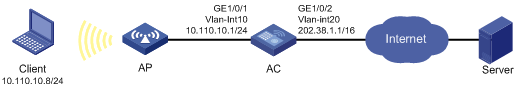
Configuration procedure
# Assign IP addresses to interfaces. (Details not shown.)
# Configure a one-to-one static NAT mapping between the private address 10.110.10.8 and the public address 202.38.1.100.
<AC> system-view
[AC] nat static outbound 10.110.10.8 202.38.1.100
# Enable static NAT on VLAN-interface 20.
[AC] interface vlan-interface 20
[AC-Vlan-interface20] nat static enable
Verifying the configuration
# Verify that the client at 10.110.10.8/24 can access the server on the Internet. (Details not shown.)
# Display static NAT configuration.
[AC] display nat static
Static NAT mappings:
Totally 1 outbound static NAT mappings.
IP-to-IP:
Local IP : 10.110.10.8
Global IP : 202.38.1.100
Config status: Active
Interfaces enabled with static NAT:
Totally 1 interfaces enabled with static NAT.
Interface: Vlan-interface20
Config status: Active
# Display NAT session information.
[AC] display nat session verbose
Initiator:
Source IP/port: 10.110.10.8/42496
Destination IP/port: 202.38.1.111/2048
DS-Lite tunnel peer: -
VPN instance/VLAN ID/Inline ID: -/-/-
Protocol: ICMP(1)
Inbound interface: Vlan-interface10
Responder:
Source IP/port: 202.38.1.111/42496
Destination IP/port: 202.38.1.100/0
DS-Lite tunnel peer: -
VPN instance/VLAN ID/Inline ID: -/-/-
Protocol: ICMP(1)
Inbound interface: Vlan-interface20
State: ICMP_REPLY
Application: INVALID
Start time: 2012-08-16 09:30:49 TTL: 27s
Initiator->Responder: 5 packets 420 bytes
Responder->Initiator: 5 packets 420 bytes
Total sessions found: 1
Outbound dynamic NAT configuration example
Network requirements
As shown in Figure 50, a company has a private address 192.168.0.0/16 and two public IP addresses 202.38.1.2 and 202.38.1.3. Configure outbound dynamic NAT to allow only internal users on subnet 192.168.1.0/24 to access the Internet.
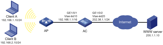
Configuration procedure
# Assign IP addresses to interfaces. (Details not shown.)
# Configure address group 0, and add an address range from 202.38.1.2 to 202.38.1.3 to the group.
<AC> system-view
[AC] nat address-group 0
[AC-address-group-0] address 202.38.1.2 202.38.1.3
[AC-address-group-0] quit
# Configure ACL 2000, and create a rule to permit packets only from subnet 192.168.1.0/24 to pass through.
[AC] acl basic 2000
[AC-acl-ipv4-basic-2000] rule permit source 192.168.1.0 0.0.0.255
[AC-acl-ipv4-basic-2000] quit
# Enable outbound dynamic PAT on interface VLAN-interface 20. The source IP addresses of the packets permitted by the ACL rule is translated into the addresses in address group 0.
[AC] interface vlan-interface 20
[AC-Vlan-interface20] nat outbound 2000 address-group 0
Verifying the configuration
# Verify that Client A can access the WWW server, but Client B cannot. (Details not shown.)
# Display all NAT configuration and statistics.
[AC] display nat all
NAT address group information:
Totally 1 NAT address groups.
Address group 0:
Port range: 1-65535
Address information:
Start address End address
202.38.1.2 202.38.1.3
NAT outbound information:
Totally 1 NAT outbound rules.
Interface: Vlan-interface20
ACL: 2000
Address group: 0
Port-preserved: N NO-PAT: N Reversible: N
Config status: Active
NAT logging:
Log enable : Disabled
Flow-begin : Disabled
Flow-end : Disabled
Flow-active : Disabled
Port-block-assign : Disabled
Port-block-withdraw : Disabled
Alarm : Disabled
NAT mapping behavior:
Mapping mode : Address and Port-Dependent
ACL : ---
Config status: Active
NAT ALG:
DNS : Enabled
FTP : Disabled
H323 : Disabled
ICMP-ERROR : Enabled
ILS : Disabled
MGCP : Disabled
NBT : Disabled
PPTP : Enabled
RTSP : Enabled
RSH : Disabled
SCCP : Disabled
SIP : Disabled
SQLNET : Disabled
TFTP : Disabled
XDMCP : Disabled
# Display NAT session information generated when Client A accesses the WWW server.
[AC] display nat session verbose
Initiator:
Source IP/port: 192.168.1.10/52992
Destination IP/port: 200.1.1.10/2048
DS-Lite tunnel peer: -
VPN instance/VLAN ID/Inline ID: -/-/-
Protocol: ICMP(1)
Inbound interface: Vlan-interface10
Responder:
Source IP/port: 200.1.1.10/4
Destination IP/port: 202.38.1.3/0
DS-Lite tunnel peer: -
VPN instance/VLAN ID/Inline ID: -/-/-
Protocol: ICMP(1)
Inbound interface: Vlan-interface20
State: ICMP_REPLY
Application: INVALID
Start time: 2012-08-15 14:53:29 TTL: 12s
Initiator->Responder: 1 packets 84 bytes
Responder->Initiator: 1 packets 84 bytes
Configuring load sharing
If a routing protocol finds multiple equal-cost best routes to the same destination, the device forwards packets over the equal-cost routes to implement load sharing.
Feature and hardware compatibility
|
Hardware series |
Model |
Load sharing compatibility |
|
WX1800H series |
WX1804H WX1810H WX1820H WX1840H |
Yes |
|
WX3800H series |
WX3820H WX3840H |
No |
|
WX5800H series |
WX5860H |
No |
Configuring per-packet or per-flow load sharing
Load sharing can be implemented in one of the following ways:
· Per-packet—The device forwards packets over equal-cost routes.
· Per-flow—The device forwards flows over equal-cost routes. Packets of one flow travel along the same routes. You can configure the device to identify a flow based on the following criteria: source IP address, destination IP address, source port number, destination port number, and IP protocol number.
To configure per-flow or per-packet load sharing:
|
Step |
Command |
Remarks |
|
1. Enter system view. |
system-view |
N/A |
|
2. Configure load sharing. |
ip load-sharing mode { per-flow [ dest-ip | dest-port | ip-pro | src-ip | src-port ] * | per-packet } global |
By default, the device performs per-flow load sharing. |
Optimizing IP performance
Command and hardware compatibility
The WX1800H series access controllers do not support the slot keyword or the slot-number argument.
Enabling an interface to forward directed broadcasts destined for the directly connected network
This task allows an interface to forward directed broadcasts destined for the directly connected network.
A directed broadcast packet is destined for all hosts on a specific network. In the destination IP address of the directed broadcast, the network ID identifies the target network, and the host ID is made up of all ones.
Configuration procedure
To enable an interface to forward directed broadcasts destined to the directly connected network:
|
Step |
Command |
Remarks |
|
1. Enter system view. |
system-view |
N/A |
|
2. Enter interface view. |
interface interface-type interface-number |
N/A |
|
3. Enable the interface to forward directed broadcasts destined for the directly connected network. |
ip forward-broadcast |
By default, an interface cannot forward directed broadcasts destined for the directly connected network. |
Configuration example
Network requirements
As shown in Figure 51, the default gateway of the host is the IP address 1.1.1.2/24 of VLAN-interface 3 of the AC.
The switch can receive directed broadcasts from the host to IP address 2.2.2.255.
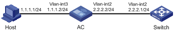
Configuration procedure
1. Configure the AC:
# Specify IP addresses for VLAN-interface 3 and VLAN-interface 2.
<AC> system-view
[AC] interface vlan-interface 3
[AC-Vlan-interface3] ip address 1.1.1.2 24
[AC-Vlan-interface3] quit
[AC] interface vlan-interface 2
[AC-Vlan-interface2] ip address 2.2.2.2 24
# Enable VLAN-interface 2 to forward directed broadcasts directed for the directly connected network.
[AC-Vlan-interface2] ip forward-broadcast
# Configure a static route to the host.
<SwitchB> system-view
[SwitchB] ip route-static 1.1.1.1 24 2.2.2.2
# Specify an IP address for VLAN-interface 2.
[Switch] interface vlan-interface 2
[Switch-Vlan-interface2] ip address 2.2.2.1 24
# Enable VLAN-interface 2 to receive directed broadcasts destined for the directly connected network.
[Switch-Vlan-interface2] ip forward-broadcast
After the configurations are completed, if you ping the subnet-directed broadcast address 2.2.2.255 on the host, VLAN-interface 2 of the switch can receive the ping packets. If you remove the ip forward-broadcast configuration on any switch, the interface cannot receive the ping packets.
Setting MTU for an interface
When a packet exceeds the MTU of the output interface, the device processes it in one of the following ways:
· If the packet disallows fragmentation, the device discards it.
· If the packet allows fragmentation, the device fragments it and forwards the fragments.
Fragmentation and reassembling consume system resources, so set the appropriate MTU for an interface based on the network environment to avoid fragmentation.
To set the MTU for an interface:
|
Step |
Command |
Remarks |
|
1. Enter system view. |
system-view |
N/A |
|
2. Enter interface view. |
interface interface-type interface-number |
N/A |
|
3. Set the MTU for the interface. |
ip mtu mtu-size |
By default, the MTU is not set. |
Setting TCP MSS for an interface
The maximum segment size (MSS) option informs the receiver of the largest segment that the sender can accept. Each end announces its MSS during TCP connection establishment. If the size of a TCP segment is smaller than the MSS of the receiver, TCP sends the TCP segment without fragmentation. If not, it fragments the segment according to the receiver's MSS.
If you set the TCP MSS on an interface, the size of each TCP segment received or sent on the interface cannot exceed the MSS value.
This configuration takes effect only for TCP connections established after the configuration rather than the TCP connections that already exist.
This configuration is effective only for IP packets.
To set the TCP MSS for the interface:
|
Step |
Command |
Remarks |
|
1. Enter system view. |
system-view |
N/A |
|
2. Enter interface view. |
interface interface-type interface-number |
N/A |
|
3. Set the TCP MSS for the interface. |
tcp mss value |
By default, the TCP MSS is not set. |
Configuring TCP path MTU discovery
|
|
IMPORTANT: All devices on a TCP connection must be enabled to send ICMP error messages by using the ip unreachables enable command. |
TCP path MTU discovery (in RFC 1191) discovers the path MTU between the source and destination ends of a TCP connection. It works as follows:
1. A TCP source device sends a packet with the Don't Fragment (DF) bit set.
2. A router discards the packet that exceeds the MTU of the outgoing interface and returns an ICMP error message. The error message contains the MTU of the outgoing interface.
3. Upon receiving the ICMP message, the TCP source device calculates the current path MTU of the TCP connection.
4. The TCP source device sends subsequent TCP segments that each are smaller than the MSS (MSS = path MTU – IP header length – TCP header length).
If the TCP source device still receives ICMP error messages when the MSS is smaller than 32 bytes, the TCP source device will fragment packets.
An ICMP error message received from a router that does not support RFC 1191 has the MTU of the outgoing interface set to 0. Upon receiving the ICMP message, the TCP source device selects the path MTU smaller than the current path MTU from the MTU table as described in RFC 1191. Based on the selected path MTU, the TCP source device calculates the TCP MSS. The MTU table contains MTUs of 68, 296, 508, 1006, 1280, 1492, 2002, 4352, 8166, 17914, 32000, and 65535 bytes. Because the minimum TCP MSS specified by the system is 32 bytes, the actual minimum MTU is 72 bytes.
After you enable TCP path MTU discovery, all new TCP connections will detect the path MTU. The device uses the path MTU to calculate the MSS to avoid IP fragmentation.
The path MTU uses the following aging mechanism to ensure that the source device can increase the path MTU when the minimum link MTU on the path increases:
· When the TCP source device receives an ICMP error message, it reduces the path MTU and starts an aging timer for the path MTU.
· After the aging timer expires, the source device uses a larger MSS in the MTU table, as described in RFC 1191.
· If no ICMP error message is received within two minutes, the source device increases the MSS again until the MSS negotiated during TCP three-way handshake is reached.
To enable TCP path MTU discovery:
|
Step |
Command |
Remarks |
|
1. Enter system view. |
system-view |
N/A |
|
2. Enable TCP path MTU discovery. |
tcp path-mtu-discovery [ aging age-time | no-aging ] |
The default setting is disabled. |
Enabling TCP SYN Cookie
A TCP connection is established through a three-way handshake:
1. The sender sends a SYN packet to the server.
2. The server receives the SYN packet, establishes a TCP semi-connection in SYN_RECEIVED state, and replies with a SYN ACK packet to the sender.
3. The sender receives the SYN ACK packet and replies with an ACK packet. A TCP connection is established.
An attacker can exploit this mechanism to mount SYN Flood attacks. The attacker sends a large number of SYN packets, but does not respond to the SYN ACK packets from the server. As a result, the server establishes a large number of TCP semi-connections and can no longer handle normal services.
SYN Cookie can protect the server from SYN Flood attacks. When the server receives a SYN packet, it responds with a SYN ACK packet without establishing a TCP semi-connection. The server establishes a TCP connection and enters ESTABLISHED state only when it receives an ACK packet from the client.
To enable TCP SYN Cookie:
|
Step |
Command |
Remarks |
|
1. Enter system view. |
system-view |
N/A |
|
2. Enable SYN Cookie. |
tcp syn-cookie enable |
The default setting is disabled. |
Setting the TCP buffer size
|
Step |
Command |
Remarks |
|
1. Enter system view. |
system-view |
N/A |
|
2. Set the size of TCP receive/send buffer. |
tcp window window-size |
The default buffer size is 64 KB. |
Setting TCP timers
You can set the following TCP timers:
· SYN wait timer—TCP starts the SYN wait timer after sending a SYN packet. Within the SYN wait timer if no response is received or the upper limit on TCP connection tries is reached, TCP fails to establish the connection.
· FIN wait timer—TCP starts the FIN wait timer when the state changes to FIN_WAIT_2. If no FIN packet is received within the timer interval, TCP terminates the connection. If a FIN packet is received, TCP changes the connection state to TIME_WAIT. If a non-FIN packet is received, TCP restarts the timer, and tears down the connection when the timer expires.
To set TCP timers:
|
Step |
Command |
Remarks |
|
1. Enter system view. |
system-view |
N/A |
|
2. Set TCP timers. |
· Set the TCP SYN wait
timer: · Set the TCP FIN wait
timer: |
By default: · The TCP SYN wait timer is 75 seconds. · The TCP FIN wait timer is 675 seconds. |
Enabling sending ICMP error messages
Perform this task to enable sending ICMP error messages, including redirect, time exceeded, and destination unreachable messages.
· ICMP redirect messages
A host that has only one default route sends all packets to the default gateway. The default gateway sends an ICMP redirect message to inform the host of a correct next hop by following these rules:
? The receiving and sending interfaces are the same.
? The selected route is not created or modified by any ICMP redirect messages.
? The selected route is not destined for 0.0.0.0.
? There is no source route option in the received packet.
ICMP redirect messages simplify host management and enable hosts to gradually optimize their routing table.
· ICMP time exceeded messages
A device sends ICMP time exceeded messages by following these rules:
? The device sends the source an ICMP TTL exceeded in transit message when the following conditions are met:
- The received packet is not destined for the device.
- The TTL field of the packet is 1.
? When the device receives the first fragment of an IP datagram destined for it, it starts a timer. If the timer expires before all the fragments of the datagram are received, the device sends an ICMP fragment reassembly time exceeded message to the source.
· ICMP destination unreachable messages
A device sends ICMP destination unreachable messages by following these rules:
? The device sends the source an ICMP network unreachable message when the following conditions are met:
- The packet does not match any route.
- No default route exists in the routing table.
? The device sends the source an ICMP protocol unreachable message when the following conditions are met:
- The packet is destined for the device.
- The transport layer protocol of the packet is not supported by the device.
|
|
NOTE: If a DHCP enabled device receives an ICMP echo reply without sending any ICMP echo requests, the device does not send any ICMP protocol unreachable messages to the source. For more information about DHCP, see Layer 3—IP Services Configuration Guide. |
? The device sends the source an ICMP port unreachable message when the following conditions are met:
- The UDP packet is destined for the device.
- The packet's port number does not match the corresponding process.
? The device sends the source an ICMP source route failed message when the following conditions are met:
- The source uses Strict Source Routing to send packets.
- The intermediate device finds that the next hop specified by the source is not directly connected.
? The device sends the source an ICMP fragmentation needed and DF set message when the following conditions are met:
- The MTU of the sending interface is smaller than the packet.
- The packet has DF set.
To enable sending ICMP error messages:
|
Step |
Command |
Remarks |
|
1. Enter system view. |
system-view |
N/A |
|
2. Enable sending ICMP error messages. |
· Enable sending ICMP redirect messages: · Enable sending ICMP time exceeded messages: · Enable sending ICMP destination
unreachable messages: |
The default settings are disabled. |
Sending ICMP error messages facilitates network management, but sending excessive ICMP messages increases network traffic. The device performance degrades if it receives a lot of malicious ICMP messages that cause it to respond with ICMP error messages.
To prevent such problems, you can disable the device from sending ICMP error messages. A device that is disabled from sending ICMP time exceeded messages does not send ICMP TTL exceeded in transit messages. However, it can still send ICMP fragment reassembly time exceeded messages.
Configuring rate limit for ICMP error messages
To avoid sending excessive ICMP error messages within a short period that might cause network congestion, you can limit the rate at which ICMP error messages are sent. A token bucket algorithm is used with one token representing one ICMP error message.
A token is placed in the bucket at intervals until the maximum number of tokens that the bucket can hold is reached.
A token is removed from the bucket when an ICMP error message is sent. When the bucket is empty, ICMP error messages are not sent until a new token is placed in the bucket.
To configure rate limit for ICMP error messages:
|
Step |
Command |
Remarks |
|
1. Enter system view. |
system-view |
N/A |
|
2. Set the bucket size and the interval for tokens to arrive in the bucket for ICMP error messages. |
ip icmp error-interval milliseconds [ bucketsize ] |
By default, the bucket allows a maximum of 10 tokens. A token is placed in the bucket at an interval of 100 milliseconds. To disable the ICMP rate limit, set the interval to 0 milliseconds. |
Specifying the source address for ICMP packets
Perform this task to specify the source IP address for outgoing ping echo request and ICMP error messages. H3C recommends that you specify the IP address of the loopback interface as the source IP address. This feature helps users to locate the sending device easily.
If you specify an IP address in the ping command, ping echo requests use the specified address as the source IP address rather than the IP address specified by the ip icmp source command.
To specify the source IP address for ICMP packets:
|
Step |
Command |
Remarks |
|
1. Enter system view. |
system-view |
N/A |
|
2. Specify the source address for outgoing ICMP packets. |
ip icmp source ip-address |
By default, the device uses the IP address of the sending interface as the source IP address for outgoing ICMP packets. |
Enabling IPv4 local fragment reassembly
Perform this task to enable the local reassembly feature for IPv4 fragments that are destined for the local device.
In a multichassis IRF fabric, this feature enables the receiving subordinate to reassemble the received IPv4 fragments instead of delivering them to the master for reassembly. It improves the fragment reassembly performance. This feature applies only to fragments received by the same subordinate in the IRF fabric.
To enable IPv4 local fragment reassembly:
|
Step |
Command |
Remarks |
|
1. Enter system view. |
N/A |
|
|
2. Enable IPv4 local fragment reassembly. |
By default, IPv4 local fragment reassembly is disabled. |
Displaying and maintaining IP performance optimization
Execute display commands in any view and reset commands in user view.
|
Task |
Command |
|
Display brief information about RawIP connections. |
display rawip [ slot slot-number ] |
|
Display detailed information about RawIP connections. |
display rawip verbose [ slot slot-number [ pcb pcb-index ] ] |
|
Display brief information about TCP connections. |
display tcp [ slot slot-number ] |
|
Display brief information about TCP proxy. |
|
|
Display the usage of non-well known ports for TCP proxy. |
display tcp-proxy port-info slot slot-number |
|
Display detailed information about TCP connections. |
display tcp verbose [ slot slot-number [ pcb pcb-index ] ] |
|
Display brief information about UDP connections. |
display udp [ slot slot-number ] |
|
Display detailed information about UDP connections. |
display udp verbose [ slot slot-number [ pcb pcb-index ] ] |
|
Display IP packet statistics. |
display ip statistics [ slot slot-number ] |
|
Display TCP traffic statistics. |
display tcp statistics [ slot slot-number ] |
|
Display UDP traffic statistics. |
display udp statistics [ slot slot-number ] |
|
Display ICMP statistics. |
display icmp statistics [ slot slot-number ] |
|
Clear IP packet statistics. |
reset ip statistics [ slot slot-number ] |
|
Clear TCP traffic statistics. |
reset tcp statistics |
|
Clear UDP traffic statistics. |
reset udp statistics |
Configuring basic IPv6 settings
Overview
IPv6, also called IP next generation (IPng), was designed by the IETF as the successor to IPv4. One significant difference between IPv6 and IPv4 is that IPv6 increases the IP address size from 32 bits to 128 bits.
IPv6 features
Simplified header format
IPv6 removes several IPv4 header fields or moves them to the IPv6 extension headers to reduce the length of the basic IPv6 packet header. The basic IPv6 packet header has a fixed length of 40 bytes to simplify IPv6 packet handling and improve forwarding efficiency. Although the IPv6 address size is four times the IPv4 address size, the basic IPv6 packet header size is only twice the size of the option-less IPv4 packet header.
Figure 52 IPv4 packet header format and basic IPv6 packet header format
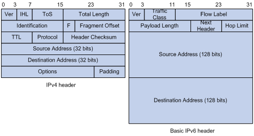
Larger address space
IPv6 can provide 3.4 x 1038 addresses to meet the requirements of hierarchical address assignment for both public and private networks.
Hierarchical address structure
IPv6 uses a hierarchical address structure to speed up route lookup and reduce the IPv6 routing table size through route aggregation.
Address autoconfiguration
To simplify host configuration, IPv6 supports stateful and stateless address autoconfiguration.
· Stateful address autoconfiguration enables a host to acquire an IPv6 address and other configuration information from a server (for example, a DHCPv6 server). For more information about DHCPv6 server, see "Configuring the DHCPv6 server."
· Stateless address autoconfiguration enables a host to automatically generate an IPv6 address and other configuration information by using its link-layer address and the prefix information advertised by a router.
To communicate with other hosts on the same link, a host automatically generates a link-local address based on its link-layer address and the link-local address prefix (FE80::/10).
Built-in security
IPv6 defines extension headers to support IPsec. IPsec provides end-to-end security and enhances interoperability among different IPv6 applications.
QoS support
The Flow Label field in the IPv6 header allows the device to label the packets of a specific flow for special handling.
Enhanced neighbor discovery mechanism
The IPv6 neighbor discovery protocol uses a group of ICMPv6 messages to manage information exchange among neighboring nodes on the same link. The group of ICMPv6 messages replaces ARP messages, ICMPv4 router discovery messages, and ICMPv4 redirect messages and provides a series of other functions.
Flexible extension headers
IPv6 eliminates the Options field in the header and introduces optional extension headers to provide scalability and improve efficiency. The Options field in the IPv4 packet header contains a maximum of 40 bytes, whereas the IPv6 extension headers are restricted to the maximum size of IPv6 packets.
IPv6 addresses
IPv6 address formats
An IPv6 address is represented as a set of 16-bit hexadecimals separated by colons (:). An IPv6 address is divided into eight groups, and each 16-bit group is represented by four hexadecimal numbers, for example, 2001:0000:130F:0000:0000:09C0:876A:130B.
To simplify the representation of IPv6 addresses, you can handle zeros in IPv6 addresses by using the following methods:
· The leading zeros in each group can be removed. For example, the above address can be represented in a shorter format as 2001:0:130F:0:0:9C0:876A:130B.
· If an IPv6 address contains one or more consecutive groups of zeros, they can be replaced by a double colon (::). For example, the above address can be represented in the shortest format as 2001:0:130F::9C0:876A:130B.
|
|
IMPORTANT: A double colon can appear once or not at all in an IPv6 address. This limit allows the device to determine how many zeros the double colon represents and correctly convert it to zeros to restore a 128-bit IPv6 address. |
An IPv6 address consists of an address prefix and an interface ID, which are equivalent to the network ID and the host ID of an IPv4 address.
An IPv6 address prefix is written in IPv6-address/prefix-length notation. The prefix-length is a decimal number indicating how many leftmost bits of the IPv6 address are in the address prefix.
IPv6 address types
IPv6 addresses include the following types:
· Unicast address—An identifier for a single interface, similar to an IPv4 unicast address. A packet sent to a unicast address is delivered to the interface identified by that address.
· Multicast address—An identifier for a set of interfaces (typically belonging to different nodes), similar to an IPv4 multicast address. A packet sent to a multicast address is delivered to all interfaces identified by that address.
Broadcast addresses are replaced by multicast addresses in IPv6.
· Anycast address—An identifier for a set of interfaces (typically belonging to different nodes). A packet sent to an anycast address is delivered to the nearest interface among the interfaces identified by that address. The nearest interface is chosen according to the routing protocol's measure of distance.
The type of an IPv6 address is designated by the first several bits, called the format prefix.
Table 6 Mappings between address types and format prefixes
|
Type |
Format prefix (binary) |
IPv6 prefix ID |
|
|
Unicast address |
Unspecified address |
00...0 (128 bits) |
::/128 |
|
Loopback address |
00...1 (128 bits) |
::1/128 |
|
|
Link-local address |
1111111010 |
FE80::/10 |
|
|
Global unicast address |
Other forms |
N/A |
|
|
Multicast address |
11111111 |
FF00::/8 |
|
|
Anycast address |
Anycast addresses use the unicast address space and have the identical structure of unicast addresses. |
||
Unicast addresses
Unicast addresses include global unicast addresses, link-local unicast addresses, the loopback address, and the unspecified address.
· Global unicast addresses—Equivalent to public IPv4 addresses, global unicast addresses are provided for Internet service providers. This type of address allows for prefix aggregation to restrict the number of global routing entries.
· Link-local addresses—Used for communication among link-local nodes for neighbor discovery and stateless autoconfiguration. Packets with link-local source or destination addresses are not forwarded to other links.
· A loopback address—0:0:0:0:0:0:0:1 (or ::1). It has the same function as the loopback address in IPv4. It cannot be assigned to any physical interface. A node uses this address to send an IPv6 packet to itself.
· An unspecified address—0:0:0:0:0:0:0:0 (or ::). It cannot be assigned to any node. Before acquiring a valid IPv6 address, a node fills this address in the source address field of IPv6 packets. The unspecified address cannot be used as a destination IPv6 address.
Multicast addresses
IPv6 multicast addresses listed in Table 7 are reserved for special purposes.
Table 7 Reserved IPv6 multicast addresses
|
Address |
Application |
|
FF01::1 |
Node-local scope all-nodes multicast address. |
|
FF02::1 |
Link-local scope all-nodes multicast address. |
|
FF01::2 |
Node-local scope all-routers multicast address. |
|
FF02::2 |
Link-local scope all-routers multicast address. |
Multicast addresses also include solicited-node addresses. A node uses a solicited-node multicast address to acquire the link-layer address of a neighboring node on the same link and to detect duplicate addresses. Each IPv6 unicast or anycast address has a corresponding solicited-node address. The format of a solicited-node multicast address is FF02:0:0:0:0:1:FFXX:XXXX. FF02:0:0:0:0:1:FF is fixed and consists of 104 bits, and XX:XXXX is the last 24 bits of an IPv6 unicast address or anycast address.
EUI-64 address-based interface identifiers
An interface identifier is 64-bit long and uniquely identifies an interface on a link. Interfaces generate EUI-64 address-based interface identifiers differently.
· On an IEEE 802 interface (such as an Ethernet interface and a VLAN interface)—The interface identifier is derived from the link-layer address (typically a MAC address) of the interface. The MAC address is 48-bit long.
To obtain an EUI-64 address-based interface identifier, follow these steps:
a. Insert the 16-bit binary number 1111111111111110 (hexadecimal value of FFFE) behind the 24th high-order bit of the MAC address.
b. Invert the universal/local (U/L) bit (the seventh high-order bit). This operation makes the interface identifier have the same local or global significance as the MAC address.
Figure 53 Converting a MAC address into an EUI-64 address-based interface identifier
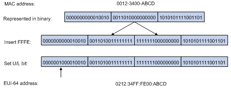
· On a tunnel interface—The lower 32 bits of the EUI-64 address-based interface identifier are the source IPv4 address of the tunnel interface. The higher 32 bits of the EUI-64 address-based interface identifier of an ISATAP tunnel interface are 0000:5EFE, whereas those of other tunnel interfaces are all zeros. For more information about tunnels, see "Configuring tunneling."
· On an interface of another type (such as a serial interface)—The EUI-64 address-based interface identifier is generated randomly by the device.
IPv6 ND protocol
The IPv6 Neighbor Discovery (ND) protocol uses the following ICMPv6 messages:
Table 8 ICMPv6 messages used by ND
|
ICMPv6 message |
Type |
Function |
|
Neighbor Solicitation (NS) |
135 |
Acquires the link-layer address of a neighbor. |
|
Verifies whether a neighbor is reachable. |
||
|
Detects duplicate addresses. |
||
|
Neighbor Advertisement (NA) |
136 |
Responds to an NS message. |
|
Notifies the neighboring nodes of link layer changes. |
||
|
Router Solicitation (RS) |
133 |
Requests an address prefix and other configuration information for autoconfiguration after startup. |
|
Router Advertisement (RA) |
134 |
Responds to an RS message. |
|
Advertises information, such as the Prefix Information options and flag bits. |
||
|
Redirect |
137 |
Informs the source host of a better next hop on the path to a particular destination when certain conditions are met. |
Address resolution
This function is similar to ARP in IPv4. An IPv6 node acquires the link-layer addresses of neighboring nodes on the same link through NS and NA messages. Figure 54 shows how Host A acquires the link-layer address of Host B on the same link.
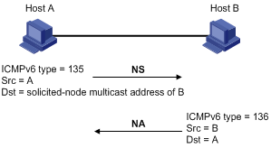
The address resolution procedure is as follows:
1. Host A multicasts an NS message. The source address of the NS message is the IPv6 address of the sending interface of Host A. The destination address is the solicited-node multicast address of Host B. The NS message body contains the link-layer address of Host A and the target IPv6 address.
2. After receiving the NS message, Host B determines whether the target address of the packet is its IPv6 address. If it is, Host B learns the link-layer address of Host A, and then unicasts an NA message containing its link-layer address.
3. Host A acquires the link-layer address of Host B from the NA message.
Neighbor reachability detection
After Host A acquires the link-layer address of its neighbor Host B, Host A can use NS and NA messages to test reachability of Host B as follows:
1. Host A sends an NS message whose destination address is the IPv6 address of Host B.
2. If Host A receives an NA message from Host B, Host A decides that Host B is reachable. Otherwise, Host B is unreachable.
Duplicate address detection
After Host A acquires an IPv6 address, it performs Duplicate Address Detection (DAD) to check whether the address is being used by any other node. This is similar to gratuitous ARP in IPv4. DAD is accomplished through NS and NA messages.
Figure 55 Duplicate address detection
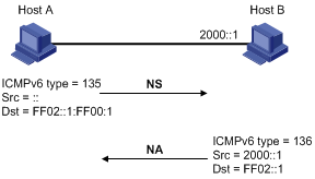
1. Host A sends an NS message. The source address is the unspecified address and the destination address is the corresponding solicited-node multicast address of the IPv6 address to be detected. The NS message body contains the detected IPv6 address.
2. If Host B uses this IPv6 address, Host B returns an NA message that contains its IPv6 address.
3. Host A knows that the IPv6 address is being used by Host B after receiving the NA message from Host B. If receiving no NA message, Host A decides that the IPv6 address is not in use and uses this address.
Router/prefix discovery and stateless address autoconfiguration
A node performs router/prefix discovery and stateless address autoconfiguration as follows:
1. At startup, a node sends an RS message to request configuration information from a router.
2. The router returns an RA message containing the Prefix Information option and other configuration information. (The router also periodically sends an RA message.)
3. The node automatically generates an IPv6 address and other configuration parameters according to the configuration information in the RA message.
The generated IPv6 address is valid within the valid lifetime and becomes invalid when the valid lifetime expires.
After the preferred lifetime expires, the node cannot use the generated IPv6 address to establish new connections, but can receive packets destined for the IPv6 address. The preferred lifetime cannot be greater than the valid lifetime.
Redirection
Upon receiving a packet from a host, the gateway sends an ICMPv6 redirect message to inform the host of a better next hop when the following conditions are met:
· The interface receiving the packet is the same as the interface forwarding the packet.
· The selected route is not created or modified by an ICMPv6 redirect message.
· The selected route is not a default route on the device.
· The forwarded IPv6 packet does not contain the routing extension header.
IPv6 path MTU discovery
The links that a packet passes from a source to a destination can have different MTUs, among which the minimum MTU is the path MTU. If a packet exceeds the path MTU, the source end fragments the packet to reduce the processing pressure on intermediate devices and to use network resources effectively.
A source end uses path MTU discovery to find the path MTU to a destination, as shown in Figure 56.
Figure 56 Path MTU discovery process
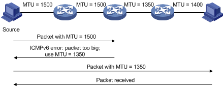
1. The source host sends a packet no larger than its MTU to the destination host.
2. If the MTU of a device's output interface is smaller than the packet, the device performs the following operations:
? Discards the packet.
? Returns an ICMPv6 error message containing the interface MTU to the source host.
3. Upon receiving the ICMPv6 error message, the source host performs the following operations:
? Uses the returned MTU to limit the packet size.
? Performs fragmentation.
? Sends the fragments to the destination host.
4. Step 2 and step 3 are repeated until the destination host receives the packet. In this way, the source host finds the minimum MTU of all links in the path to the destination host.
IPv6 transition technologies
IPv6 transition technologies enable communication between IPv4 and IPv6 networks, including dual stack (RFC 2893) and tunneling (RFC 2893).
Dual stack
Dual stack is the most direct transition approach. A network node that supports both IPv4 and IPv6 is a dual-stack node. A dual-stack node configured with an IPv4 address and an IPv6 address can forward both IPv4 and IPv6 packets. An application that supports both IPv4 and IPv6 prefers IPv6 at the network layer.
Dual stack is suitable for communication between IPv4 nodes or between IPv6 nodes. It is the basis of all transition technologies. However, it does not solve the IPv4 address depletion issue because each dual-stack node must have a globally unique IPv4 address.
Tunneling
Tunneling uses one network protocol to encapsulate the packets of another network protocol and transfers them over the network.
Protocols and standards
Protocols and standards related to IPv6 include:
· RFC 1881, IPv6 Address Allocation Management
· RFC 1887, An Architecture for IPv6 Unicast Address Allocation
· RFC 1981, Path MTU Discovery for IP version 6
· RFC 2375, IPv6 Multicast Address Assignments
· RFC 2460, Internet Protocol, Version 6 (IPv6) Specification
· RFC 2464, Transmission of IPv6 Packets over Ethernet Networks
· RFC 2526, Reserved IPv6 Subnet Anycast Addresses
· RFC 3307, Allocation Guidelines for IPv6 Multicast Addresses
· RFC 4191, Default Router Preferences and More-Specific Routes
· RFC 4291, IP Version 6 Addressing Architecture
· RFC 4443, Internet Control Message Protocol (ICMPv6) for the Internet Protocol Version 6 (IPv6) Specification
· RFC 4861, Neighbor Discovery for IP Version 6 (IPv6)
· RFC 4862, IPv6 Stateless Address Autoconfiguration
Command and hardware compatibility
The WX1800H series access controllers do not support the slot keyword or the slot-number argument.
IPv6 basics configuration task list
Assigning IPv6 addresses to interfaces
This section describes how to configure an IPv6 global unicast address, an IPv6 link-local address, and an IPv6 anycast address.
Configuring an IPv6 global unicast address
Use one of the following methods to configure an IPv6 global unicast address for an interface:
· EUI-64 IPv6 address—The IPv6 address prefix of the interface is manually configured, and the interface ID is generated automatically by the interface.
· Manual configuration—The IPv6 global unicast address is manually configured.
· Stateless address autoconfiguration—The IPv6 global unicast address is generated automatically based on the address prefix information contained in the RA message.
· Prefix-specific address autoconfiguration—The IPv6 global unicast address is generated automatically based on the prefix specified by its ID. The prefix can be manually configured or obtained through DHCPv6.
You can configure multiple IPv6 global unicast addresses on an interface.
Manually configured global unicast addresses (including EUI-64 IPv6 addresses) take precedence over automatically generated ones. If you manually configure a global unicast address with the same address prefix as an existing global unicast address on an interface, the manually configured one takes effect. However, it does not overwrite the automatically generated address. If you remove the manually configured global unicast address, the device uses the automatically generated one.
EUI-64 IPv6 address
To configure an interface to generate an EUI-64 IPv6 address:
|
Step |
Command |
Remarks |
|
1. Enter system view. |
system-view |
N/A |
|
2. Enter interface view. |
interface interface-type interface-number |
N/A |
|
3. Configure the interface to generate an EUI-64 IPv6 address. |
ipv6 address { ipv6-address prefix-length | ipv6-address/prefix-length } eui-64 |
By default, no EUI-64 IPv6 address is configured on an interface. |
Manual configuration
To configure an IPv6 global unicast address for an interface:
|
Step |
Command |
Remarks |
|
1. Enter system view. |
system-view |
N/A |
|
2. Enter interface view. |
interface interface-type interface-number |
N/A |
|
3. Configure an IPv6 global unicast address for the interface. |
ipv6 address { ipv6-address prefix-length | ipv6-address/prefix-length } |
By default, no IPv6 global unicast address is configured on an interface. |
Stateless address autoconfiguration
To configure an interface to generate an IPv6 address through stateless address autoconfiguration:
|
Step |
Command |
Remarks |
|
1. Enter system view. |
system-view |
N/A |
|
2. Enter interface view. |
interface interface-type interface-number |
N/A |
|
3. Enable stateless address autoconfiguration. |
ipv6 address auto |
By default, no IPv6 global unicast address is configured on an interface. Using the undo ipv6 address auto command on an interface removes all IPv6 global unicast addresses and link-local addresses that are automatically generated on the interface. |
After this configuration is completed, the interface automatically generates an IPv6 global unicast address by using the address prefix in the received RA message and the interface ID. On an IEEE 802 interface (such as an Ethernet interface or a VLAN interface), the interface ID is generated based on the interface's MAC address and is globally unique. An attacker can exploit this rule to identify the sending device easily.
To fix the vulnerability, you can configure the temporary address feature. With this feature, an IEEE 802 interface generates the following addresses:
· Public IPv6 address—Includes the address prefix in the RA message and a fixed interface ID generated based on the MAC address of the interface.
· Temporary IPv6 address—Includes the address prefix in the RA message and a random interface ID generated through MD5.
You can also configure the interface to preferentially use the temporary IPv6 address as the source address of sent packets. When the valid lifetime of the temporary IPv6 address expires, the interface removes the address and generates a new one. This feature enables the system to send packets with different source addresses through the same interface. If the temporary IPv6 address cannot be used because of a DAD conflict, the public IPv6 address is used.
The preferred lifetime and valid lifetime for a temporary IPv6 address are determined as follows:
· The preferred lifetime of a temporary IPv6 address takes the smaller of the following values:
? The preferred lifetime of the address prefix in the RA message.
? The preferred lifetime configured for temporary IPv6 addresses minus DESYNC_FACTOR (a random number in the range of 0 to 600 seconds).
· The valid lifetime of a temporary IPv6 address takes the smaller of the following values:
? The valid lifetime of the address prefix.
? The valid lifetime configured for temporary IPv6 addresses.
To configure the temporary address feature:
|
Step |
Command |
Remarks |
|
1. Enter system view. |
system-view |
N/A |
|
2. Enable the temporary IPv6 address feature. |
ipv6 temporary-address [ valid-lifetime preferred-lifetime ] |
By default, the temporary IPv6 address feature is disabled. |
|
3. Enable the system to preferentially use the temporary IPv6 address as the source address of the packet. |
ipv6 prefer temporary-address |
By default, the system does not preferentially use the temporary IPv6 address as the source address of the packet. |
To generate a temporary address, an interface must be enabled with stateless address autoconfiguration. Temporary IPv6 addresses do not overwrite public IPv6 addresses, so an interface can have multiple IPv6 addresses with the same address prefix but different interface IDs.
If an interface fails to generate a public IPv6 address because of a prefix conflict or other reasons, it does not generate any temporary IPv6 address.
Prefix-specific address autoconfiguration
This task allows you to specify an IPv6 prefix for an interface to automatically generate an IPv6 global unicast address and advertise the prefix. You must specify the IPv6 prefix by its ID.
To specify an IPv6 prefix for an interface to generate an IPv6 address and advertise the prefix:
|
Step |
Command |
Remarks |
|
1. Enter system view. |
system-view |
N/A |
|
2. Configure an IPv6 prefix. |
· (Method 1) Configure a static IPv6 prefix: · (Method 2):Use DHCPv6 to
obtain a dynamic IPv6 prefix: |
By default, the device does not have any static or dynamic IPv6 prefix. |
|
3. Enter interface view. |
interface interface-type interface-number |
N/A |
|
4. Specify an IPv6 prefix for an interface to automatically generate an IPv6 global unicast address and advertise the prefix. |
By default, no IPv6 prefix is specified for the interface to automatically generate an IPv6 global unicast address. |
Configuring an IPv6 link-local address
Configure IPv6 link-local addresses using one of the following methods:
· Automatic generation—The device automatically generates a link-local address for an interface according to the link-local address prefix (FE80::/10) and the link-layer address of the interface.
· Manual assignment—Manually configure an IPv6 link-local address for an interface.
An interface can have only one link-local address. To avoid link-local address conflicts, H3C recommends that you use the automatic generation method. If both methods are used, the manual assignment takes precedence.
· If you first use automatic generation and then manual assignment, the manually assigned link-local address overwrites the automatically generated one.
· If you first use manual assignment and then automatic generation, both of the following occur:
? The link-local address is still the manually assigned one.
? The automatically generated link-local address does not take effect. If you delete the manually assigned address, the automatically generated link-local address takes effect.
Configuring automatic generation of an IPv6 link-local address for an interface
|
Step |
Command |
Remarks |
|
1. Enter system view. |
system-view |
N/A |
|
2. Enter interface view. |
interface interface-type interface-number |
N/A |
|
3. Configure the interface to automatically generate an IPv6 link-local address. |
ipv6 address auto link-local |
By default, no link-local address is configured on an interface. After an IPv6 global unicast address is configured on the interface, a link-local address is generated automatically. |
Manually specifying an IPv6 link-local address for an interface
|
Step |
Command |
Remarks |
|
1. Enter system view. |
system-view |
N/A |
|
2. Enter interface view. |
interface interface-type interface-number |
N/A |
|
3. Manually specify an IPv6 link-local address for the interface. |
ipv6 address ipv6-address link-local |
By default, no link-local address is configured on an interface. After an IPv6 global unicast address is configured on the interface, a link-local address is generated automatically. |
After you configure an IPv6 global unicast address for an interface, the interface automatically generates a link-local address. The automatically generated link-local address is the same as the one generated by using the ipv6 address auto link-local command. If a link-local address is manually assigned to an interface, this manual link-local address takes effect. If the manually assigned link-local address is removed, the automatically generated link-local address takes effect.
Using the undo ipv6 address auto link-local command on an interface only removes the link-local address generated by the ipv6 address auto link-local command. If the interface has an IPv6 global unicast address, it still has a link-local address. If the interface has no IPv6 global unicast address, it has no link-local address.
Configuring an IPv6 anycast address
|
Step |
Command |
Remarks |
|
1. Enter system view. |
system-view |
N/A |
|
2. Enter interface view. |
interface interface-type interface-number |
N/A |
|
3. Configure an IPv6 anycast address. |
ipv6 address { ipv6-address prefix-length | ipv6-address/prefix-length } anycast |
By default, no IPv6 anycast address is configured on an interface. |
Configuring IPv6 ND
This section describes how to configure IPv6 ND.
Configuring a static neighbor entry
A neighbor entry stores information about a link-local node. The entry can be created dynamically through NS and NA messages, or configured statically.
The device uniquely identifies a static neighbor entry by using the neighbor's IPv6 address and the number of the Layer 3 interface that connects to the neighbor. You can configure a static neighbor entry by using one of the following methods:
· Method 1—Associate a neighbor's IPv6 address and link-layer address with the local Layer 3 interface.
If you use Method 1, the device automatically finds the Layer 2 port connected to the neighbor.
· Method 2—Associate a neighbor's IPv6 address and link-layer address with a Layer 2 port in a VLAN.
If you use Method 2, make sure the Layer 2 port belongs to the specified VLAN and the corresponding VLAN interface already exists. The device associates the VLAN interface with the neighbor IPv6 address to identify the static neighbor entry.
To configure a static neighbor entry:
|
Step |
Command |
Remarks |
|
1. Enter system view. |
system-view |
N/A |
|
2. Configure a static neighbor entry. |
ipv6 neighbor ipv6-address mac-address { vlan-id port-type port-number | interface interface-type interface-number } |
By default, no static neighbor entry exists on the device. |
Setting the maximum number of dynamic neighbor entries
The device can dynamically acquire the link-layer address of a neighboring node through NS and NA messages and add it into the neighbor table. When the number of dynamic neighbor entries reaches the threshold, the interface stops learning neighbor information. To prevent an interface from occupying too many neighbor table resources, you can set the maximum number of dynamic neighbors that an interface can learn.
To set the maximum number of dynamic neighbor entries:
|
Step |
Command |
Remarks |
|
1. Enter system view. |
system-view |
N/A |
|
2. Enter interface view. |
interface interface-type interface-number |
N/A |
|
3. Set the maximum number of dynamic neighbor entries that the interface can learn. |
ipv6 neighbors max-learning-num number |
The default setting depends on the device model. For more information, see Layer 3–IP Services Command Reference. |
Setting the aging timer for ND entries in stale state
ND entries in stale state have an aging timer. If an ND entry in stale state is not refreshed before the timer expires, the ND entry changes to the delay state. If it is still not refreshed in 5 seconds, the ND entry changes to the probe state, and the device sends an NS message three times. If no response is received, the device removes the ND entry.
To set the aging timer for ND entries in stale state:
|
Step |
Command |
Remarks |
|
1. Enter system view. |
system-view |
N/A |
|
2. Set the aging timer for ND entries in stale state. |
ipv6 neighbor stale-aging aging-time |
The default setting is 240 minutes. |
Minimizing link-local ND entries
Perform this task to minimize link-local ND entries assigned to the driver. Link-local ND entries refer to ND entries that contain link-local addresses.
By default, the device assigns all ND entries to the driver. With this feature enabled, the device does not add newly learned link-local ND entries whose link local addresses are not the next hop of any route into the driver. This saves driver resources.
This feature takes effect only on newly learned link-local ND entries.
To minimize link-local ND entries:
|
Step |
Command |
Remarks |
|
1. Enter system view. |
system-view |
N/A |
|
2. Minimize link-local ND entries. |
ipv6 neighbor link-local minimize |
By default, the device assigns all ND entries to the driver. |
Setting the hop limit
The device advertises the hop limit in RA messages. All RA message receivers use the advertised value to fill in the Hop Limit field for IPv6 packets to be sent. To disable the device from advertising the hop limit, use the ipv6 nd ra hop-limit unspecified command.
To set the hop limit:
|
Step |
Command |
Remarks |
|
1. Enter system view. |
system-view |
N/A |
|
2. Set the Hop Limit field in the IP header. |
ipv6 hop-limit value |
The default setting is 64. |
Configuring parameters for RA messages
You can enable an interface to send RA messages, and configure the interval for sending RA messages and parameters in RA messages. After receiving an RA message, a host can use these parameters to perform corresponding operations. Table 9 describes the configurable parameters in an RA message.
Table 9 Parameters in an RA message and their descriptions
|
Parameter |
Description |
|
Hop Limit |
Maximum number of hops in RA messages. A host receiving the RA message fills the value in the Hop Limit field of sent IPv6 packets. |
|
Prefix information |
After receiving the prefix information, the hosts on the same link can perform stateless autoconfiguration. |
|
MTU |
Guarantees that all nodes on the link use the same MTU. |
|
M flag |
Determines whether a host uses stateful autoconfiguration to obtain an IPv6 address. If the M flag is set to 1, the host uses stateful autoconfiguration (for example, from a DHCPv6 server) to obtain an IPv6 address. Otherwise, the host uses stateless autoconfiguration to generate an IPv6 address according to its link-layer address and the prefix information in the RA message. |
|
O flag |
Determines whether a host uses stateful autoconfiguration to obtain configuration information other than IPv6 address. If the O flag is set to 1, the host uses stateful autoconfiguration (for example, from a DHCPv6 server) to obtain configuration information other than IPv6 address. Otherwise, the host uses stateless autoconfiguration. |
|
Router Lifetime |
Tells the receiving hosts how long the advertising router can live. If the lifetime of a router is 0, the router cannot be used as the default gateway. |
|
Retrans Timer |
If the device does not receive a response message within the specified time after sending an NS message, it retransmits the NS message. |
|
Reachable Time |
If the neighbor reachability detection shows that a neighbor is reachable, the device considers the neighbor reachable within the specified reachable time. If the device needs to send a packet to the neighbor after the specified reachable time expires, the device reconfirms whether the neighbor is reachable. |
|
Router Preference |
Specifies the router preference in a RA message. A host selects a router as the default gateway according to the router preference. If router preferences are the same, the host selects the router from which the first RA message is received. |
The maximum interval for sending RA messages should be less than (or equal to) the router lifetime in RA messages. In this way, the router can be updated by an RA message before expiration.
The values of the NS retransmission timer and the reachable time configured for an interface are sent in RA messages to hosts. This interface sends NS messages at the interval of the NS retransmission timer and considers a neighbor reachable within the reachable time.
Enabling sending of RA messages
|
Step |
Command |
Remarks |
|
1. Enter system view. |
system-view |
N/A |
|
2. Enter interface view. |
interface interface-type interface-number |
N/A |
|
3. Enable sending of RA messages. |
undo ipv6 nd ra halt |
The default setting is disabled. |
|
4. Set the maximum and minimum intervals for sending RA messages. |
ipv6 nd ra interval max-interval-value min-interval-value |
By default, the maximum interval for sending RA messages is 600 seconds, and the minimum interval is 200 seconds. The device sends RA messages at random intervals between the maximum interval and the minimum interval. The minimum interval should be less than or equal to 0.75 times the maximum interval. |
Configuring parameters for RA messages
|
Step |
Command |
Remarks |
|
1. Enter system view. |
system-view |
N/A |
|
2. Enter interface view. |
interface interface-type interface-number |
N/A |
|
3. Configure the prefix information in RA messages. |
ipv6 nd ra prefix { ipv6-prefix prefix-length | ipv6-prefix/prefix-length } valid-lifetime preferred-lifetime [ no-autoconfig | off-link ] * |
By default, no prefix information is configured for RA messages, and the IPv6 address of the interface sending RA messages is used as the prefix information. If the IPv6 address is manually configured, the prefix uses a fixed valid lifetime of 2592000 seconds (30 days) and a preferred lifetime of 604800 seconds (7 days). If the IPv6 address is automatically obtained, the prefix uses the valid lifetime and preferred lifetime configured for the IPv6 address. |
|
4. Turn off the MTU option in RA messages. |
ipv6 nd ra no-advlinkmtu |
By default, RA messages contain the MTU option. |
|
5. Specify unlimited hops in RA messages. |
ipv6 nd ra hop-limit unspecified |
By default, the maximum number of hops in RA messages is 64. |
|
6. Set the M flag bit to 1. |
ipv6 nd autoconfig managed-address-flag |
By default, the M flag bit is set to 0 in RA advertisements. Hosts receiving the advertisements will obtain IPv6 addresses through stateless autoconfiguration. |
|
7. Set the O flag bit to 1. |
ipv6 nd autoconfig other-flag |
By default, the O flag bit is set to 0 in RA advertisements. Hosts receiving the advertisements will acquire other configuration information through stateless autoconfiguration. |
|
8. Set the router lifetime in RA messages. |
ipv6 nd ra router-lifetime value |
By default, the router lifetime is 1800 seconds. |
|
9. Set the NS retransmission timer. |
ipv6 nd ns retrans-timer value |
By default, an interface sends NS messages every 1000 milliseconds, and the value of the Retrans Timer field in RA messages is 0. |
|
10. Set the router preference in RA messages. |
ipv6 nd router-preference { high | low | medium } |
By default, the router preference is medium. |
|
11. Set the reachable time. |
ipv6 nd nud reachable-time value |
By default, the neighbor reachable time is 30000 milliseconds, and the value of the Reachable Time field in sent RA messages is 0. |
Setting the maximum number of attempts to send an NS message for DAD
An interface sends an NS message for DAD for an obtained IPv6 address. The interface resends the NS message if it does not receive a response within the time specified by the ipv6 nd ns retrans-timer command. If the interface receives no response after making the maximum attempts specified by the ipv6 nd dad attempts command, the interface uses the IPv6 address.
To set the attempts to send an NS message for DAD:
|
Step |
Command |
Remarks |
|
1. Enter system view. |
system-view |
N/A |
|
2. Enter interface view. |
interface interface-type interface-number |
N/A |
|
3. Set the number of attempts to send an NS message for DAD. |
ipv6 nd dad attempts value |
The default setting is 1. When the value argument is set to 0, DAD is disabled. |
Enabling ND proxy
About ND proxy
ND proxy enables a device to answer an NS message requesting the hardware address of a host on another network. With ND proxy, hosts in different broadcast domains can communicate with each other as they would on the same network.
ND proxy includes common ND proxy and local ND proxy.
· Common ND proxy.
As shown in Figure 57, VLAN-interface 2 with IPv6 address 4:1::99/64 and VLAN-interface 3 with IPv6 address 4:2::99/64 belong to different subnets. Host A and Host B reside on the same network but in different broadcast domains.
Figure 57 Application environment of ND proxy
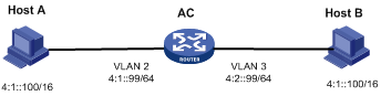
Because Host A's IPv6 address is on the same subnet as Host B's, Host A directly sends an NS message to obtain Host B's MAC address. However, Host B cannot receive the NS message because they belong to different broadcast domains.
To solve this problem, enable common ND proxy on VLAN-interface 2 and VLAN-interface 3 of the AC. The AC replies to the NS message from Host A, and forwards packets from other hosts to Host B.
· Local ND proxy.
As shown in Figure 58, Host A belongs to VLAN 2 and Host B belongs to VLAN 3. Host A and Host B connect to GigabitEthernet 1/0/1 and GigabitEthernet 1/0/3, respectively.
Figure 58 Application environment of local ND proxy
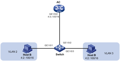
Because Host A's IPv6 address is on the same subnet as Host B's, Host A directly sends an NS message to obtain Host B's MAC address. However, Host B cannot receive the NS message because they belong to different VLANs.
To solve this problem, enable local ND proxy on GigabitEthernet 1/0/2 of the AC so that the AC can forward messages between Host A and Host B.
Local ND proxy implements Layer 3 communication for two hosts in the following cases:
? The two hosts connect to ports of the same device and the ports must be in different VLANs.
? The two hosts connect to isolated Layer 2 ports in the same isolation group of a VLAN.
? If super VLAN is used, the two hosts must belong to different sub VLANs.
? If Private VLAN is used, the two hosts must belong to different secondary VLANs.
Configuration procedure
You can enable common ND proxy and local ND proxy in VLAN interface view, Layer 3 Ethernet interface view, or Layer 3 Ethernet subinterface view.
To enable common ND proxy:
|
Step |
Command |
Remarks |
|
1. Enter system view. |
system-view |
N/A |
|
2. Enter interface view. |
interface interface-type interface-number |
N/A |
|
3. Enable common ND proxy. |
proxy-nd enable |
By default, common ND proxy is disabled. |
To enable local ND proxy:
|
Step |
Command |
Remarks |
|
1. Enter system view. |
system-view |
N/A |
|
2. Enter interface view. |
interface interface-type interface-number |
N/A |
|
3. Enable local ND proxy. |
local-proxy-nd enable |
By default, local ND proxy is disabled. |
Configuring a customer-side port
By default, the device associates an ND entry with routing information when the device learns an ND entry. The ND entry provides the next hop information for routing. To save hardware resources, you can use this command to specify a port that connects a user terminal as a customer-side port. The device will not associate the routing information with the learned ND entries.
To configure a customer-side port:
|
Step |
Command |
Remarks |
|
1. Enter system view. |
system-view |
N/A |
|
2. Create a VLAN interface and enter its view. |
interface vlan-interface vlan-interface-id |
If the VLAN interface exists, you directly enter its view. |
|
3. Specify the VLAN interface as a customer-side port. |
ipv6 nd mode uni |
By default, a port acts as a network-side port. |
Configuring path MTU discovery
Setting the interface MTU
IPv6 routers do not support packet fragmentation. If the size of a packet exceeds the MTU of the output interface, the router discards the packet and sends a packet too big message to the source host. The source host fragments the packet according to the MTU. To avoid this situation, set a proper interface MTU.
To set the interface MTU:
|
Step |
Command |
Remarks |
|
1. Enter system view. |
system-view |
N/A |
|
2. Enter interface view. |
interface interface-type interface-number |
N/A |
|
3. Set the interface MTU. |
ipv6 mtu mtu-size |
By default, no interface MTU is set. |
Setting a static path MTU for an IPv6 address
You can set a static path MTU for an IPv6 address. Before sending a packet to the IPv6 address, the device compares the MTU of the output interface with the static path MTU. If the packet exceeds the smaller one of the two values, the device fragments the packet according to the smaller value. After sending the fragmented packets, the device dynamically finds the path MTU to a destination host (see "IPv6 path MTU discovery").
To set a static path MTU for a destination IPv6 address:
|
Step |
Command |
Remarks |
|
1. Enter system view. |
system-view |
N/A |
|
2. Set a static path MTU for a destination IPv6 address. |
ipv6 pathmtu ipv6-address value |
By default, no path MTU is set for any IPv6 address. |
Setting the aging time for dynamic path MTUs
After the device dynamically finds the path MTU to a destination host (see "IPv6 path MTU discovery"), it performs the following operations:
· Sends packets to the destination host based on the path MTU.
· Starts the aging timer.
When the aging timer expires, the device removes the dynamic path MTU and finds the path MTU again.
To set the aging time for dynamic path MTUs:
|
Step |
Command |
Remarks |
|
1. Enter system view. |
system-view |
N/A |
|
2. Set the aging time for dynamic path MTUs. |
ipv6 pathmtu age age-time |
The default setting is 10 minutes. The aging time is invalid for a static path MTU. |
Controlling sending ICMPv6 messages
This section describes how to configure ICMPv6 message sending.
Configuring the rate limit for ICMPv6 error messages
To avoid sending excessive ICMPv6 error messages within a short period that might cause network congestion, you can limit the rate at which ICMPv6 error messages are sent. A token bucket algorithm is used with one token representing one ICMPv6 error message.
A token is placed in the bucket at intervals until the maximum number of tokens that the bucket can hold is reached.
A token is removed from the bucket when an ICMPv6 error message is sent. When the bucket is empty, ICMPv6 error messages are not sent until a new token is placed in the bucket.
To configure the rate limit for ICMPv6 error messages:
|
Step |
Command |
Remarks |
|
1. Enter system view. |
system-view |
N/A |
|
2. Set the bucket size and the interval for tokens to arrive in the bucket for ICMPv6 error messages. |
ipv6 icmpv6 error-interval milliseconds [ bucketsize ] |
By default, the bucket allows a maximum of 10 tokens. A token is placed in the bucket at an interval of 100 milliseconds. To disable the ICMPv6 rate limit, set the interval to 0 milliseconds. |
Enabling replying to multicast echo requests
The device does not respond to multicast echo requests by default. In some scenarios, you must enable the device to answer multicast echo requests so the source host can obtain needed information.
To enable the device to answer multicast echo requests:
|
Step |
Command |
Remarks |
|
1. Enter system view. |
system-view |
N/A |
|
2. Enable replying to multicast echo requests. |
ipv6 icmpv6 multicast-echo-reply enable |
By default, this feature is disabled. |
Enabling sending ICMPv6 destination unreachable messages
The device sends the source the following ICMPv6 destination unreachable messages:
· ICMPv6 No Route to Destination message—A packet to be forwarded does not match any route.
· ICMPv6 Beyond Scope of Source Address message—The destination is beyond the scope of the source IPv6 address. For example, a packet's source IPv6 address is a link-local address, and its destination IPv6 address is a global unicast address.
· ICMPv6 Port Unreachable message—No port process on the destination device exists for a received UDP packet.
If a device is generating ICMPv6 destination unreachable messages incorrectly, disable the sending of ICMPv6 destination unreachable messages to prevent attack risks.
To enable sending ICMPv6 destination unreachable messages:
|
Step |
Command |
Remarks |
|
1. Enter system view. |
system-view |
N/A |
|
2. Enable sending ICMPv6 destination unreachable messages. |
ipv6 unreachables enable |
By default, this feature is disabled. |
Enabling sending ICMPv6 time exceeded messages
The device sends the source ICMPv6 time exceeded messages as follows:
· If a received packet is not destined for the device and its hop limit is 1, the device sends an ICMPv6 hop limit exceeded in transit message to the source.
· Upon receiving the first fragment of an IPv6 datagram destined for the device, the device starts a timer. If the timer expires before all the fragments arrive, the device sends an ICMPv6 fragment reassembly time exceeded message to the source.
If the device receives large numbers of malicious packets, its performance degrades greatly because it must send back ICMP time exceeded messages. To prevent such attacks, disable sending ICMPv6 time exceeded messages.
To enable sending ICMPv6 time exceeded messages:
|
Step |
Command |
Remarks |
|
1. Enter system view. |
system-view |
N/A |
|
2. Enable sending ICMPv6 time exceeded messages. |
ipv6 hoplimit-expires enable |
The default setting is disabled. |
Enabling sending ICMPv6 redirect messages
Upon receiving a packet from a host, the device sends an ICMPv6 redirect message to inform the host of a better next hop when the following conditions are met:
· The interface receiving the packet is the interface forwarding the packet.
· The selected route is not created or modified by any ICMPv6 redirect messages.
· The selected route is not a default route.
· The forwarded packet does not contain the routing extension header.
The ICMPv6 redirect feature simplifies host management by enabling hosts that hold few routes to optimize their routing table gradually. However, to avoid adding too many routes on hosts, this feature is disabled by default.
To enable sending ICMPv6 redirect messages:
|
Step |
Command |
Remarks |
|
1. Enter system view. |
system-view |
N/A |
|
2. Enable sending ICMPv6 redirect messages. |
ipv6 redirects enable |
By default, sending ICMPv6 redirect messages is disabled. |
Specifying the source address for ICMPv6 packets
Perform this task to specify the source IPv6 address for outgoing ping echo requests and ICMPv6 error messages. It is a good practice to specify the IPv6 address of the loopback interface as the source IPv6 address. This feature helps users to easily locate the sending device.
If you specify an IPv6 address in the ping command, ping echo requests use the specified address as the source IPv6 address. Otherwise, ping echo requests use the IPv6 address specified by the ipv6 icmpv6 source command.
To specify the source IPv6 address for ICMPv6 packets:
|
Step |
Command |
Remarks |
|
1. Enter system view. |
system-view |
N/A |
|
2. Specify an IPv6 address as the source address for outgoing ICMPv6 packets. |
ipv6 icmpv6 source ipv6-address |
By default, the device uses the IPv6 address of the sending interface as the source IPv6 address for outgoing ICMPv6 packets. |
Enabling IPv6 local fragment reassembly
Perform this task to enable the local reassembly feature for IPv6 fragments that are destined for the local device.
In a multichassis IRF fabric, this feature enables the receiving subordinate to reassemble the received IPv6 fragments instead of delivering them to the master for reassembly. It improves the fragment reassembly performance. This feature applies only to fragments received by the same subordinate in the IRF fabric.
To enable IPv6 local fragment reassembly:
|
Step |
Command |
Remarks |
|
1. Enter system view. |
system-view |
N/A |
|
2. Enable IPv6 local fragment reassembly. |
ipv6 reassemble local enable |
By default, IPv6 local fragment reassembly is disabled. This feature applies only to fragments received by the same LPU. |
Enabling a device to discard IPv6 packets that contain extension headers
This feature enables a device to discard a received IPv6 packet in which the extension headers cannot be processed by the device.
To enable a device to discard IPv6 packets that contain extension headers:
|
Step |
Command |
Remarks |
|
1. Enter system view. |
system-view |
N/A |
|
2. Enable the device to discard IPv6 packets that contain extension headers. |
ipv6 extension-header drop enable |
By default, the device does not discard IPv6 packets that contain extension headers. |
Displaying and maintaining IPv6 basics
Execute display commands in any view and reset commands in user view.
|
Task |
Command |
|
Display IPv6 FIB entries. |
display ipv6 fib [ ipv6-address [ prefix-length ] ] |
|
Display IPv6 information about the interface. |
display ipv6 interface [ interface-type [ interface-number ] ] [ brief ] |
|
Display IPv6 prefix information about the interface. |
display ipv6 interface interface-type interface-number prefix |
|
Display neighbor information. |
display ipv6 neighbors { { ipv6-address | all | dynamic | static } [ slot slot-number ] | interface interface-type interface-number | vlan vlan-id } [ verbose ] |
|
Display the total number of neighbor entries. |
display ipv6 neighbors { { all | dynamic | static } [ slot slot-number ] | interface interface-type interface-number | vlan vlan-id } count |
|
Display the IPv6 path MTU information. |
display ipv6 pathmtu { ipv6-address | { all | dynamic | static } [ count ] } |
|
Display the IPv6 prefix information. |
|
|
Display IPv6 and ICMPv6 statistics. |
display ipv6 statistics [ slot slot-number ] |
|
Display brief information about IPv6 RawIP connections. |
display ipv6 rawip [ slot slot-number ] |
|
Display detailed information about IPv6 RawIP connections. |
display ipv6 rawip verbose [ slot slot-number [ pcb pcb-index ] ] |
|
Display router renumbering statistics. |
|
|
Display brief information about IPv6 TCP connections. |
display ipv6 tcp [ slot slot-number ] |
|
Display brief information about IPv6 TCP proxy. |
|
|
Display the usage of non-well known ports for IPv6 TCP proxy. |
display ipv6 tcp-proxy port-info slot slot-number |
|
Display detailed information about IPv6 TCP connections. |
display ipv6 tcp verbose [ slot slot-number [ pcb pcb-index ] ] |
|
Display brief information about IPv6 UDP connections. |
display ipv6 udp [ slot slot-number ] |
|
Display detailed information about IPv6 UDP connections. |
display ipv6 udp verbose [ slot slot-number [ pcb pcb-index ] ] |
|
Display ICMPv6 traffic statistics. |
display ipv6 icmp statistics [ slot slot-number ] |
|
Display IPv6 TCP traffic statistics. |
display tcp statistics [ slot slot-number ] |
|
Display IPv6 UDP traffic statistics. |
display udp statistics [ slot slot-number ] |
|
Clear IPv6 neighbor information. |
reset ipv6 neighbors { all | dynamic | interface interface-type interface-number | slot slot-number | static } |
|
Clear path MTUs. |
reset ipv6 pathmtu { all | dynamic | static } |
|
Clear IPv6 and ICMPv6 packet statistics. |
reset ipv6 statistics [ slot slot-number ] |
|
Clear IPv6 TCP traffic statistics. |
reset tcp statistics |
|
Clear IPv6 UDP traffic statistics. |
reset udp statistics |
Basic IPv6 configuration example
Network requirements
As shown in Figure 59, an AC and an AP are connected through a switch. Add the Ethernet ports of the AC and AP to corresponding VLANs. Configure IPv6 addresses for the VLAN interfaces and verify that they are connected. Assign a global unicast address 2001::1/64 to VLAN-interface 1 of the AC.
Enable IPv6 on the client to automatically obtain an IPv6 address through IPv6 ND.
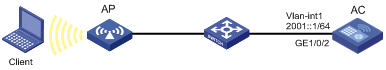
Configuration procedure
This example assumes that the VLAN interfaces have been created on the AC.
1. Configure the AC:
# Configure the basic functions of the AC. For more information, see WLAN Configuration Guide. (Details not shown.)
# Specify a global unicast address for VLAN-interface 1, and allow it to advertise RA messages. By default, the interfaces do not advertise RA messages.
[AC] interface vlan-interface 1
[AC-Vlan-interface1] ipv6 address 2001::1/64
[AC-Vlan-interface1] undo ipv6 nd ra halt
2. Configure the client:
Enable IPv6 for the host to automatically obtain an IPv6 address through IPv6 ND.
# Display neighbor information for GigabitEthernet 1/0/2 on the AC.
[AC-Vlan-interface1] display ipv6 neighbors interface gigabitEthernet 1/0/2
Type: S-Static D-Dynamic O-Openflow R-Rule I-Invalid
IPv6 Address Link-layer VID Interface State T Age
FE80::215:E9FF:FEA6:7D14 0015-e9a6-7d14 1 WLAN-BSS1/0/1 STALE D 1238
2001::15B:E0EA:3524:E791 0015-e9a6-7d14 1 WLAN-BSS1/0/1 STALE D 1248
The output shows that the IPv6 global unicast address that the client obtained is 2001::15B:E0EA:3524:E791.
Verifying the configuration
# Display the IPv6 interface settings on the AC.
[AC-Vlan-interface1] display ipv6 interface vlan-interface 1
Vlan-interface1 current state :UP
Line protocol current state :UP
IPv6 is enabled, link-local address is FE80::20F:E2FF:FE00:1C0
Global unicast address(es):
2001::1, subnet is 2001::/64
Joined group address(es):
FF02::1
FF02::2
FF02::18C
FF02::1:FF00:1
FF02::1:FFB5:ED00
FF0E::18C
MTU is 1500 bytes
ND DAD is enabled, number of DAD attempts: 1
ND reachable time is 30000 milliseconds
ND retransmit interval is 1000 milliseconds
ND advertised reachable time is 0 milliseconds
ND advertised retransmit interval is 0 milliseconds
ND router advertisements are sent every 600 seconds
ND router advertisements live for 1800 seconds
Hosts use stateless autoconfig for addresses
IPv6 Packet statistics:
InReceives: 272
InTooShorts: 0
InTruncatedPkts: 0
InHopLimitExceeds: 0
InBadHeaders: 0
InBadOptions: 0
ReasmReqds: 0
ReasmOKs: 0
InFragDrops: 0
InFragTimeouts: 0
OutFragFails: 0
InUnknownProtos: 0
InDelivers: 159
OutRequests: 1012
OutForwDatagrams: 35
InNoRoutes: 0
InTooBigErrors: 0
OutFragOKs: 0
OutFragCreates: 0
InMcastPkts: 79
InMcastNotMembers: 65
OutMcastPkts: 938
InAddrErrors: 0
InDiscards: 0
OutDiscards: 0
# Ping the AC from the client, and ping the client from the AC to verify that they are connected.
|
|
NOTE: When you ping a link-local address, use the -i parameter to specify an interface for the link-local address. |
[AC-Vlan-interface1] ping ipv6 -c 1 2001::15B:E0EA:3524:E791
PING 2001::15B:E0EA:3524:E791 : 56 data bytes, press CTRL_C to break
Reply from 2001::15B:E0EA:3524:E791
bytes=56 Sequence=1 hop limit=63 time = 3 ms
--- 2001::15B:E0EA:3524:E791 ping statistics ---
1 packet(s) transmitted
1 packet(s) received
0.00% packet loss
round-trip min/avg/max = 3/3/3 ms
The output shows that the AC can ping the client. The client can also ping the AC.
Troubleshooting IPv6 basics configuration
Symptom
An IPv6 address cannot be pinged.
Solution
1. Use the display ipv6 interface command in any view to verify that the IPv6 address of the output interface is correct and the interface is up.
2. Use the debugging ipv6 packet command in user view to enable the debugging for IPv6 packets to locate the fault.
DHCPv6 overview
DHCPv6 address/prefix assignment
An address/prefix assignment process involves two or four messages.
Rapid assignment involving two messages
As shown in Figure 60, rapid assignment operates in the following steps:
1. The DHCPv6 client sends to the DHCPv6 server a Solicit message that contains a Rapid Commit option to prefer rapid assignment.
2. If the DHCPv6 server supports rapid assignment, it responds with a Reply message containing the assigned IPv6 address/prefix and other configuration parameters. If the DHCPv6 server does not support rapid assignment, Assignment involving four messages is performed.
Figure 60 Rapid assignment involving two messages
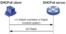
Assignment involving four messages
As shown in Figure 61, four-message assignment operates using the following steps:
1. The DHCPv6 client sends a Solicit message to request an IPv6 address/prefix and other configuration parameters.
2. The DHCPv6 server responds with an Advertise message that contains the assignable address/prefix and other configuration parameters if either of the following conditions exists:
? The Solicit message does not contain a Rapid Commit option.
? The DHCPv6 server does not support rapid assignment even though the Solicit message contains a Rapid Commit option.
3. The DHCPv6 client might receive multiple Advertise messages offered by different DHCPv6 servers. It selects an offer according to the receiving sequence and server priority, and sends a Request message to the selected server for confirmation.
4. The DHCPv6 server sends a Reply message to the client, confirming that the address/prefix and other configuration parameters are assigned to the client.
Figure 61 Assignment involving four messages
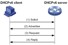
Address/prefix lease renewal
An IPv6 address/prefix assigned by a DHCPv6 server has a valid lifetime. After the valid lifetime expires, the DHCPv6 client cannot use the IPv6 address/prefix. To use the IPv6 address/prefix, the DHCPv6 client must renew the lease time.
Figure 62 Using the Renew message for address/prefix lease renewal
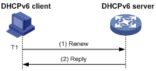
As shown in Figure 62, at T1, the DHCPv6 client sends a Renew message to the DHCPv6 server. The recommended value of T1 is half the preferred lifetime. The DHCPv6 server responds with a Reply message, informing the client whether the lease is renewed.
Figure 63 Using the Rebind message for address/prefix lease renewal
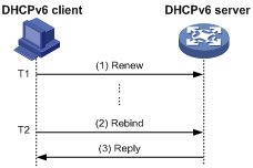
As shown in Figure 63:
· If the DHCPv6 client does not receive a response from the DHCPv6 server after sending a Renew message at T1, it multicasts a Rebind message to all DHCPv6 servers at T2. Typically, the value of T2 is 0.8 times the preferred lifetime.
· The DHCPv6 server responds with a Reply message, informing the client whether the lease is renewed.
· If the DHCPv6 client does not receive a response from any DHCPv6 server before the valid lifetime expires, the client stops using the address/prefix.
For more information about the valid lifetime and the preferred lifetime, see "Configuring basic IPv6 settings."
Stateless DHCPv6
Stateless DHCPv6 enables a device that has obtained an IPv6 address/prefix to get other configuration parameters from a DHCPv6 server.
The device performs stateless DHCPv6 if an RA message with the following flags is received from the router during stateless address autoconfiguration:
· The managed address configuration flag (M flag) is set to 0.
· The other stateful configuration flag (O flag) is set to 1.
For more information about stateless address autoconfiguration, see "Configuring basic IPv6 settings."
Figure 64 Stateless DHCPv6 operation
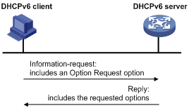
As shown in Figure 64, stateless DHCPv6 operates in the following steps:
1. The DHCPv6 client sends an Information-request message to the multicast address of all DHCPv6 servers and DHCPv6 relay agents. The Information-request message contains an Option Request option that specifies the requested configuration parameters.
2. The DHCPv6 server returns to the client a Reply message containing the requested configuration parameters.
3. The client checks the Reply message. If the obtained configuration parameters match those requested in the Information-request message, the client uses these parameters to complete configuration. If not, the client ignores the configuration parameters. If the client receives multiple replies with configuration parameters matching those requested in the Information-request message, it uses the first received reply.
Protocols and standards
· RFC 3736, Stateless Dynamic Host Configuration Protocol (DHCP) Service for IPv6
· RFC 3315, Dynamic Host Configuration Protocol for IPv6 (DHCPv6)
· RFC 2462, IPv6 Stateless Address Autoconfiguration
· RFC 3633, IPv6 Prefix Options for Dynamic Host Configuration Protocol (DHCP) version 6
Configuring the DHCPv6 server
Overview
IPv6 address assignment
As shown in Figure 65, the DHCPv6 server assigns IPv6 addresses, domain name suffixes, DNS server addresses, and other configuration parameters to DHCPv6 clients.
The IPv6 addresses assigned to the clients include the following types:
· Temporary IPv6 addresses—Frequently changed without lease renewal.
· Non-temporary IPv6 addresses—Correctly used by DHCP clients, with lease renewal.
Figure 65 IPv6 address assignment
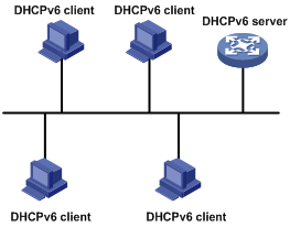
IPv6 prefix assignment
As shown in Figure 66, the DHCPv6 server assigns an IPv6 prefix to the DHCPv6 client. The client advertises the prefix information in a multicast RA message so that hosts on the subnet can automatically configure their IPv6 addresses by using the prefix.
Figure 66 IPv6 prefix assignment
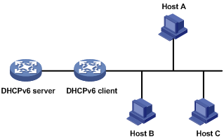
Concepts
Multicast addresses used by DHCPv6
DHCPv6 uses the multicast address FF05::1:3 to identify all site-local DHCPv6 servers. It uses the multicast address FF02::1:2 to identify all link-local DHCPv6 servers and relay agents.
DUID
A DHCP unique identifier (DUID) uniquely identifies a DHCPv6 device (DHCPv6 client, server, or relay agent). A DHCPv6 device adds its DUID in a sent packet.
Figure 67 DUID-LL format
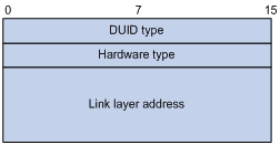
The device supports the DUID format based on link-layer address (DUID-LL) defined in RFC 3315. Figure 67 shows the DUID-LL format, which includes the following fields:
· DUID type—The device supports the DUID type of DUID-LL with the value of 0x0003.
· Hardware type—The device supports the hardware type of Ethernet with the value of 0x0001.
· Link layer address—Takes the value of the bridge MAC address of the device.
IA
Identified by an IAID, an identity association (IA) provides a construct through which a client manages the obtained addresses, prefixes, and other configuration parameters. A client can have multiple IAs, for example, one for each of its interfaces.
IAID
An IAID uniquely identifies an IA. It is chosen by the client and must be unique on the client.
PD
The DHCPv6 server creates a prefix delegation (PD) for each assigned prefix to record the following details:
· IPv6 prefix.
· Client DUID.
· IAID.
· Valid lifetime.
· Preferred lifetime.
· Lease expiration time.
· IPv6 address of the requesting client.
DHCPv6 address pool
The DHCP server selects IPv6 addresses, IPv6 prefixes, and other parameters from an address pool, and assigns them to the DHCP clients.
Address allocation mechanisms
DHCPv6 supports the following address allocation mechanisms:
· Static address allocation—To implement static address allocation for a client, create a DHCPv6 address pool, and manually bind the DUID and IAID of the client to an IPv6 address in the DHCPv6 address pool. When the client requests an IPv6 address, the DHCPv6 server assigns the IPv6 address in the static binding to the client.
· Dynamic address allocation—To implement dynamic address allocation for clients, create a DHCPv6 address pool, specify a subnet for the pool, and divide the subnet into temporary and non-temporary IPv6 address ranges. Upon receiving a DHCP request, the DHCPv6 server selects an IPv6 address from the temporary or non-temporary IPv6 address range based on the address type in the client request.
Prefix allocation mechanisms
DHCPv6 supports the following prefix allocation mechanisms:
· Static prefix allocation—To implement static prefix allocation for a client, create a DHCPv6 address pool, and manually bind the DUID and IAID of the client to an IPv6 prefix in the DHCPv6 address pool. When the client requests an IPv6 prefix, the DHCPv6 server assigns the IPv6 prefix in the static binding to the client.
· Dynamic prefix allocation—To implement dynamic prefix allocation for clients, create a DHCPv6 address pool and a prefix pool, specify a subnet for the address pool, and apply the prefix pool to the address pool. Upon receiving a DHCP request, the DHCPv6 server dynamically selects an IPv6 prefix from the prefix pool in the address pool.
Address pool selection
The DHCPv6 server observes the following principles when selecting an IPv6 address or prefix for a client:
1. If there is an address pool where an IPv6 address is statically bound to the DUID or IAID of the client, the DHCPv6 server selects this address pool. It assigns the statically bound IPv6 address or prefix and other configuration parameters to the client.
2. If the receiving interface has an address pool applied, the DHCP server selects an IPv6 address or prefix and other configuration parameters from this address pool.
3. If no static address pool is configured and no address pool is applied to the receiving interface, the DHCPv6 server selects an address pool depending on the client location.
? Client on the same subnet as the server—The DHCPv6 server compares the IPv6 address of the receiving interface with the subnets of all address pools. It selects the address pool with the longest-matching subnet.
? Client on a different subnet than the server—The DHCPv6 server compares the IPv6 address of the DHCPv6 relay agent interface closest to the client with the subnets of all address pools. It also selects the address pool with the longest-matching subnet.
To make sure IPv6 address allocation functions correctly, keep the subnet used for dynamic assignment consistent with the subnet where the interface of the DHCPv6 server or DHCPv6 relay agent resides.
IPv6 address/prefix allocation sequence
The DHCPv6 server selects an IPv6 address/prefix for a client in the following sequence:
1. IPv6 address/prefix statically bound to the client's DUID and IAID and expected by the client.
2. IPv6 address/prefix statically bound to the client's DUID and IAID.
3. IPv6 address/prefix statically bound to the client's DUID and expected by the client.
4. IPv6 address/prefix statically bound to the client's DUID.
5. IPv6 address/prefix that was ever assigned to the client.
6. Assignable IPv6 address/prefix in the address pool/prefix pool expected by the client.
7. Assignable IPv6 address/prefix in the address pool/prefix pool.
8. IPv6 address/prefix that was a conflict or passed its lease duration. If no IPv6 address/prefix is assignable, the server does not respond.
If a client moves to another subnet, the DHCPv6 server selects an IPv6 address/prefix from the address pool that matches the new subnet.
Conflicted IPv6 addresses can be assigned to other DHCPv6 clients only after the addresses are in conflict for one hour.
Configuration task list
|
Tasks at a glance |
|
(Optional.) Perform the following tasks: · Configuring IPv6 prefix assignment · Configuring IPv6 address assignment · Configuring network parameters assignment · Configuring a DHCPv6 policy for IPv6 address and prefix assignment |
|
(Required.) Configuring the DHCPv6 server on an interface |
|
(Optional.) Setting the DSCP value for DHCPv6 packets sent by the DHCPv6 server |
|
(Optional.) Configuring DHCPv6 binding auto backup |
|
(Optional.) Advertising subnets assigned to clients |
|
(Optional.) Enabling DHCPv6 logging on the DHCPv6 server |
Configuring IPv6 prefix assignment
Use the following methods to configure IPv6 prefix assignment:
· Configure a static IPv6 prefix binding in an address pool—If you bind a DUID and an IAID to an IPv6 prefix, the DUID and IAID in a request must match those in the binding before the DHCPv6 server can assign the IPv6 prefix to the DHCPv6 client. If you only bind a DUID to an IPv6 prefix, the DUID in the request must match the DUID in the binding before the DHCPv6 server can assign the IPv6 prefix to the DHCPv6 client.
· Apply a prefix pool to an address pool—The DHCPv6 server dynamically assigns an IPv6 prefix from the prefix pool in the address pool to a DHCPv6 client.
Configuration guidelines
· An IPv6 prefix can be bound to only one DHCPv6 client. You cannot modify bindings that have been created. To change the binding for a DHCPv6 client, you must delete the existing binding first.
· Only one prefix pool can be applied to an address pool. You cannot modify prefix pools that have been applied. To change the prefix pool for an address pool, you must remove the prefix pool application first.
· You can apply a prefix pool that has not been created to an address pool. The setting takes effect after the prefix pool is created.
Configuration procedure
To configure IPv6 prefix assignment:
|
Step |
Command |
Remarks |
|
1. Enter system view. |
system-view |
N/A |
|
2. (Optional.) Specify the IPv6 prefixes excluded from dynamic assignment. |
ipv6 dhcp server forbidden-prefix start-prefix/prefix-len [ end-prefix/prefix-len ] |
By default, no IPv6 prefixes in the prefix pool are excluded from dynamic assignment. If the excluded IPv6 prefix is in a static binding, the prefix still can be assigned to the client. To exclude multiple IPv6 prefix ranges, repeat this step. |
|
3. Create a prefix pool. |
ipv6 dhcp prefix-pool prefix-pool-number prefix { prefix-number | prefix/prefix-len } assign-len assign-len |
This step is required for dynamic prefix assignment. By default, no prefix pool is configured. If you specify an IPv6 prefix by its ID, make sure the IPv6 prefix is in effect. Otherwise, the configuration does not take effect. |
|
4. Create a DHCPv6 address pool and enter its view. |
ipv6 dhcp pool pool-name |
By default, no DHCPv6 address pool is configured. |
|
5. Specify an IPv6 subnet for dynamic assignment. |
network { prefix/prefix-length | prefix prefix-number [ sub-prefix/sub-prefix-length ] } [ preferred-lifetime preferred-lifetime valid-lifetime valid-lifetime ] |
By default, no IPv6 subnet is specified for dynamic assignment. The IPv6 subnets cannot be the same in different address pools. If you specify an IPv6 prefix by its ID, make sure the IPv6 prefix is in effect. Otherwise, the configuration does not take effect. |
|
6. Configure static prefix assignment, dynamic prefix assignment, or both. |
· Configure a static prefix binding: · Apply the prefix pool to the address pool: |
By default, static or dynamic prefix assignment is not configured for an address pool. To add multiple static IPv6 prefix bindings, use the static-bind prefix command multiple times. |
Configuring IPv6 address assignment
Use one of the following methods to configure IPv6 address assignment:
· Configure a static IPv6 address binding in an address pool.
If you bind a DUID and an IAID to an IPv6 address, the DUID and IAID in a request must match those in the binding before the DHCPv6 server can assign the IPv6 address to the requesting client. If you only bind a DUID to an IPv6 address, the DUID in a request must match the DUID in the binding before the DHCPv6 server can assign the IPv6 address to the requesting client.
· Specify a subnet and address ranges in an address pool.
? Non-temporary address assignment—The server selects addresses from the non-temporary address range specified by the address range command. If no non-temporary address range is specified, the server selects addresses on the subnet specified by the network command.
? Temporary address assignment—The server selects addresses from the temporary address range specified by the temporary address range command. If no temporary address range is specified in the address pool, the DHCPv6 server cannot assign temporary addresses to clients.
Configuration guidelines
· You can specify only one non-temporary address range and one temporary address range in an address pool.
· The address ranges specified by the address range and temporary address range commands must be on the subnet specified by the network command. Otherwise, the addresses are unassignable.
· Only one prefix pool can be applied to an address pool. You can apply a prefix pool that has not been created to an address pool. The setting takes effect after the prefix pool is created.
· An IPv6 address can be bound to only one DHCPv6 client. You cannot modify bindings that have been created. To change the binding for a DHCPv6 client, you must delete the existing binding first.
· Only one subnet can be specified in an address pool. If you use the network command multiple times in a DHCPv6 address pool, the most recent configuration takes effect. If you use this command to specify only new lifetimes, the settings do not affect existing leases. The IPv6 addresses assigned after the modification will use the new lifetimes.
Configuration procedure
To configure IPv6 address assignment:
|
Step |
Command |
Remarks |
|
1. Enter system view. |
system-view |
N/A |
|
2. (Optional.) Specify the IPv6 addresses excluded from dynamic assignment. |
ipv6 dhcp server forbidden-address start-ipv6-address [ end-ipv6-address ] |
By default, all IPv6 addresses except for the DHCPv6 server's IP address in a DHCPv6 address pool are assignable. If the excluded IPv6 address is in a static binding, the address still can be assigned to the client. To exclude multiple IPv6 prefix ranges, repeat this step. |
|
3. Create a DHCPv6 address pool and enter its view. |
ipv6 dhcp pool pool-name |
By default, no DHCPv6 address pool is configured. |
|
4. Specify an IPv6 subnet for dynamic assignment. |
network { prefix/prefix-length | prefix prefix-number [ sub-prefix/sub-prefix-length ] } [ preferred-lifetime preferred-lifetime valid-lifetime valid-lifetime ] |
By default, no IPv6 address subnet is specified. The IPv6 subnets cannot be the same in different address pools. If you specify an IPv6 prefix by its ID, make sure the IPv6 prefix is in effect. Otherwise, the configuration does not take effect. |
|
5. (Optional.) Specify a non-temporary IPv6 address range. |
address range start-ipv6-address end-ipv6-address [ preferred-lifetime preferred-lifetime valid-lifetime valid-lifetime ] |
By default, no non-temporary IPv6 address range is specified, and all unicast addresses on the subnet are assignable. |
|
6. (Optional.) Specify a temporary IPv6 address range. |
temporary address range start-ipv6-address end-ipv6-address [ preferred-lifetime preferred-lifetime valid-lifetime valid-lifetime ] |
By default, no temporary IPv6 address range is specified, and the DHCPv6 server cannot assign temporary IPv6 addresses. |
|
7. (Optional.) Create a static binding. |
static-bind address ipv6-address/addr-prefix-length | duid duid [ iaid iaid ] [ preferred-lifetime preferred-lifetime valid-lifetime valid-lifetime ] |
By default, no static binding is configured. To add more static bindings, repeat this step. |
Configuring network parameters assignment
In addition to IPv6 prefixes and IPv6 addresses, you can configure up to eight DNS server addresses, one domain name suffix, eight SIP server addresses, and eight SIP server domain names in an address pool.
You can configure network parameters on a DHCPv6 server by using one of the following methods:
· Configure network parameters in a DHCPv6 address pool.
· Configure network parameters in a DHCPv6 option group, and reference the option group in a DHCPv6 address pool.
Network parameters configured in a DHCPv6 address pool take precedence over those configured in a DHCPv6 option group.
Configuring network parameters in a DHCPv6 address pool
|
Step |
Command |
Remarks |
|
1. Enter system view. |
system-view |
N/A |
|
2. Create a DHCPv6 address pool and enter its view. |
ipv6 dhcp pool pool-name |
By default, no DHCPv6 address pool exists on the DHCPv6 server. |
|
3. Specify an IPv6 subnet for dynamic assignment. |
network { prefix/prefix-length | prefix prefix-number [ sub-prefix/sub-prefix-length ] } [ preferred-lifetime preferred-lifetime valid-lifetime valid-lifetime ] |
By default, no IPv6 subnet is specified. The IPv6 subnets cannot be the same in different address pools. If you specify an IPv6 prefix by its ID, make sure the IPv6 prefix is in effect. Otherwise, the configuration does not take effect. |
|
4. (Optional.) Specify a DNS server address. |
dns-server ipv6-address |
By default, no DNS server address is specified. |
|
5. (Optional.) Specify a domain name suffix. |
domain-name domain-name |
By default, no domain name suffix is specified. |
|
6. (Optional.) Specify a SIP server address or domain name. |
sip-server { address ipv6-address | domain-name domain-name } |
By default, no SIP server address or domain name is specified. |
|
7. (Optional.) Configure a self-defined DHCPv6 option. |
option code hex hex-string |
By default, no self-defined DHCPv6 option is configured. |
Configuring network parameters in a DHCPv6 option group
A DHCPv6 option group can be created by using the following methods:
· Create a static DHCPv6 option group by using the ipv6 dhcp option-group command. The static DHCPv6 option group takes precedence over the dynamic DHCPv6 option group.
· When the device acts as a DHCPv6 client, it automatically creates a dynamic DHCPv6 option group for saving the obtained parameters. For more information about creating a dynamic DHCPv6 option group, see "Configuring the DHCPv6 client."
To create a static DHCPv6 option group:
|
Step |
Command |
Remarks |
|
1. Enter system view. |
system-view |
N/A |
|
2. Create a static DHCPv6 option group and enter its view. |
ipv6 dhcp option-group option-group-number |
By default, no static DHCPv6 option group exists on the DHCPv6 server. |
|
3. (Optional.) Specify a DNS server address. |
dns-server ipv6-address |
By default, no DNS server address is specified. |
|
4. (Optional.) Specify a domain name suffix. |
domain-name domain-name |
By default, no domain name suffix is specified. |
|
5. (Optional.) Specify a SIP server address or domain name. |
sip-server { address ipv6-address | domain-name domain-name } |
By default, no SIP server address or domain name is specified. |
|
6. (Optional.) Configure a self-defined DHCPv6 option. |
option code hex hex-string |
By default, no self-defined DHCPv6 option is configured. |
|
7. Return to system view. |
quit |
N/A |
|
8. Create a DHCPv6 address pool and enter its view. |
ipv6 dhcp pool pool-name |
By default, no DHCPv6 address pool exists on the DHCPv6 server. |
|
9. Specify a DHCPv6 option group. |
option group option-group-number |
By default, no DHCPv6 option group is specified. |
Configuring a DHCPv6 policy for IPv6 address and prefix assignment
In a DHCPv6 policy, each DHCPv6 user class has a bound DHCPv6 address pool. Clients matching different user classes obtain IPv6 addresses, IPv6 prefixes, and other parameters from different address pools. The DHCPv6 policy must be applied to the interface that acts as the DHCPv6 server. When receiving a DHCPv6 request, the DHCPv6 server compares the packet against the user classes in the order that they are configured.
If a match is found and the bound address pool has assignable IPv6 addresses or prefixes, the server uses the address pool for assignment. If the bound address pool does not have assignable IPv6 addresses or prefixes, the assignment fails.
If no match is found, the server uses the default DHCPv6 address pool for assignment. If no default address pool is specified or the default address pool does not have assignable IPv6 addresses or prefixes, the assignment fails.
For successful assignment, make sure the applied DHCPv6 policy and the bound address pools exist.
A match rule cannot match an option added by the DHCPv6 relay agent, for example, Option 18 or Option 37.
To configure a DHCPv6 policy for IPv6 address and prefix assignment:
|
Step |
Command |
Remarks |
|
1. Enter system view. |
system-view |
N/A |
|
2. Create a DHCPv6 user class and enter DHCPv6 user class view. |
ipv6 dhcp class class-name |
By default, no DHCPv6 user class exists. |
|
3. Configure a match rule for the DHCPv6 user class. |
if-match rule rule-number { option option-code [ ascii ascii-string [ offset offset | partial ] | hex hex-string [ mask mask | offset offset length length | partial ] ] | relay-agent gateway-ipv6-address } |
By default, no match rule is configured for a DHCPv6 user class. |
|
4. Return to system view. |
quit |
N/A |
|
5. Create a DHCPv6 policy and enter DHCPv6 policy view. |
ipv6 dhcp policy policy-name |
By default, no DHCPv6 policy exists. |
|
6. Specify a DHCPv6 address pool for a DHCPv6 user class. |
class class-name pool pool-name |
By default, no address pool is specified for a user class. |
|
7. Specify the default DHCPv6 address pool. |
default pool pool-name |
By default, no default address pool is specified. |
|
8. Return to system view. |
quit |
N/A |
|
9. Enter interface view. |
interface interface-type interface-number |
N/A |
|
10. Apply the DHCPv6 policy to the interface. |
ipv6 dhcp apply-policy policy-name |
By default, no DHCPv6 policy is applied to an interface. |
Configuring the DHCPv6 server on an interface
Enable the DHCP server and configure one of the following address/prefix assignment methods on an interface:
· Apply an address pool on the interface—The DHCPv6 server selects an IPv6 address/prefix from the applied address pool for a requesting client. If there is no assignable IPv6 address/prefix in the address pool, the DHCPv6 server cannot to assign an IPv6 address/prefix to a client.
· Configure global address assignment on the interface—The DHCPv6 server selects an IPv6 address/prefix in the global DHCPv6 address pool that matches the server interface address or the DHCPv6 relay agent address for a requesting client.
If you configure both methods on an interface, the DHCPv6 server uses the specified address pool for address assignment without performing global address assignment.
Configuration guidelines
· An interface cannot act as a DHCPv6 server and DHCPv6 relay agent at the same time.
· Do not enable DHCPv6 server and DHCPv6 client on the same interface.
· If you use the ipv6 dhcp server command multiple times, the most recent configuration takes effect.
· You can apply an address pool that has not been created to an interface. The setting takes effect after the address pool is created.
· Only one address pool can be applied to an interface. If you use the ipv6 dhcp server apply pool command multiple times, the most recent configuration takes effect.
Configuration procedure
To configure the DHCPv6 server on an interface:
|
Step |
Command |
Remarks |
|
1. Enter system view. |
system-view |
N/A |
|
2. Enter interface view. |
interface interface-type interface-number |
N/A |
|
3. Enable the DHCPv6 server on the interface. |
ipv6 dhcp select server |
By default, the interface discards DHCPv6 packets from DHCPv6 clients. |
|
4. Configure an address/prefix assignment method. |
· Configure global address assignment: · Apply a DHCPv6 address pool to the interface: |
By default, desired address/prefix assignment and rapid assignment are disabled, and the default preference is 0. |
Setting the DSCP value for DHCPv6 packets sent by the DHCPv6 server
The DSCP value of a packet specifies the priority level of the packet and affects the transmission priority of the packet.
To set the DSCP value for DHCPv6 packets sent by the DHCPv6 server:
|
Step |
Command |
Remarks |
|
1. Enter system view. |
system-view |
N/A |
|
2. Set the DSCP value for DHCPv6 packets sent by the DHCPv6 server. |
ipv6 dhcp dscp dscp-value |
By default, the DSCP value in DHCPv6 packets sent by the DHCPv6 server is 56. |
Configuring DHCPv6 binding auto backup
The auto backup feature saves DHCPv6 bindings to a backup file, and allows the DHCPv6 server to download the bindings from the backup file at the server reboot. The bindings include the lease bindings and conflicted IPv6 addresses. They cannot survive a reboot on the DHCPv6 server.
The DHCPv6 server does not provide services during the download process. If a connection error occurs during the process and cannot be repaired in a short amount of time, you can terminate the download operation. Manual interruption allows the DHCPv6 server to provide services without waiting for the connection to be repaired.
To configure DHCPv6 binding auto backup:
|
Step |
Command |
Remarks |
|
1. Enter system view. |
system-view |
N/A |
|
2. Configure the DHCPv6 server to back up the bindings to a file. |
ipv6 dhcp server database filename { filename | url url [ username username [ password { cipher | simple } key ] ] } |
By default, the DHCPv6 server does not back up the DHCPv6 bindings. With this command executed, the DHCPv6 server backs up its bindings immediately and runs auto backup. |
|
3. (Optional.) Manually save the DHCPv6 bindings to the backup file. |
ipv6 dhcp server database update now |
N/A |
|
4. (Optional.) Set the waiting time after a DHCPv6 binding change for the DHCPv6 server to update the backup file. |
ipv6 dhcp server database update interval seconds |
The default waiting time is 300 seconds. If no DHCPv6 binding changes, the backup file is not updated. |
|
5. (Optional.) Terminate the download of DHCPv6 bindings from the backup file. |
ipv6 dhcp server database update stop |
N/A |
Advertising subnets assigned to clients
This feature enables the route management module to advertise subnets assigned to DHCPv6 clients. This feature achieves symmetric routing for traffic of the same host.
As shown in Figure 68, Router A and Router B act as both the DHCPv6 server and the BRAS device. The BRAS devices send accounting packets to the RADIUS server. To enable the BRAS devices to collect correct accounting information for each RADIUS user, configure the DHCPv6 server to advertise subnets assigned to clients. The upstream and downstream traffic of a RADIUS user will pass through the same BRAS device.
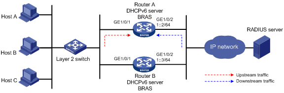
To configure the subnet advertisement feature:
|
Step |
Command |
Remarks |
|
1. Enter system view. |
system-view |
N/A |
|
2. Create an address pool and enter its view. |
ipv6 dhcp pool pool-name |
By default, no DHCPv6 address pool exists. |
|
3. Advertise the subnet assigned to DHCPv6 clients. |
network { prefix/prefix-length | prefix prefix-number [ sub-prefix/sub-prefix-length ] } [ preferred-lifetime preferred-lifetime valid-lifetime valid-lifetime ] export-route |
By default, the subnet assigned to DHCPv6 clients are not advertised. |
Enabling DHCPv6 logging on the DHCPv6 server
The DHCPv6 logging feature enables the DHCPv6 server to generate DHCPv6 logs and send them to the information center. For information about the log destination and output rule configuration in the information center, see Network Management and Monitoring Configuration Guide.
Disable this feature when the log generation affects the device performance or reduces the address and prefix allocation efficiency. For example, this situation might occur when a large number of clients frequently come online or go offline.
To configure DHCPv6 logging on the DHCPv6 server:
|
Step |
Command |
Remarks |
|
1. Enter system view. |
system-view |
N/A |
|
2. Enable DHCPv6 logging. |
ipv6 dhcp log enable |
By default, DHCPv6 logging is disabled. |
Displaying and maintaining the DHCPv6 server
Execute display commands in any view and reset commands in user view.
|
Task |
Command |
|
Display the DUID of the local device. |
display ipv6 dhcp duid |
|
Display information about a DHCPv6 option group. |
display ipv6 dhcp option-group [ option-group-number ] |
|
Display DHCPv6 address pool information. |
display ipv6 dhcp pool [ pool-name ] |
|
Display prefix pool information. |
display ipv6 dhcp prefix-pool [ prefix-pool-number ] |
|
Display DHCPv6 server information on an interface. |
display ipv6 dhcp server [ interface interface-type interface-number ] |
|
Display information about IPv6 address conflicts. |
display ipv6 dhcp server conflict [ address ipv6-address ] |
|
Display information about DHCPv6 binding auto backup |
display ipv6 dhcp server database |
|
Display information about expired IPv6 addresses. |
display ipv6 dhcp server expired [ address ipv6-address | pool pool-name ] |
|
Display information about IPv6 address bindings. |
display ipv6 dhcp server ip-in-use [ address ipv6-address | pool pool-name ] |
|
Display information about IPv6 prefix bindings. |
display ipv6 dhcp server pd-in-use [ pool pool-name | prefix prefix/prefix-len ] |
|
Display packet statistics on the DHCPv6 server. |
display ipv6 dhcp server statistics [ pool pool-name ] |
|
Clear information about IPv6 address conflicts. |
reset ipv6 dhcp server conflict [ address ipv6-address ] |
|
Clear information about expired IPv6 address bindings. |
reset ipv6 dhcp server expired [ address ipv6-address | pool pool-name ] |
|
Clear information about IPv6 address bindings. |
reset ipv6 dhcp server ip-in-use [ address ipv6-address | pool pool-name ] |
|
Clear information about IPv6 prefix bindings. |
reset ipv6 dhcp server pd-in-use [ pool pool-name | prefix prefix/prefix-len ] |
|
Clear packets statistics on the DHCPv6 server. |
reset ipv6 dhcp server statistics |
DHCPv6 server configuration examples
Dynamic IPv6 prefix assignment configuration example
Network requirements
As shown in Figure 69, the AC acts as a DHCPv6 server to assign an IPv6 prefix, a DNS server address, a domain name, a SIP server address, and a SIP server name to each DHCPv6 client.
The AC assigns prefix 2001:0410:0201::/48 to the client whose DUID is 00030001CA0006A40000, and assigns prefixes in the range of 2001:0410::/48 to 2001:0410:FFFF::/48 (excluding 2001:0410:0201::/48) to other clients. The DNS server address is 2::2:3. The DHCPv6 clients reside in the domain aaa.com. The SIP server address is 2:2::4, and the SIP server name is bbb.com.
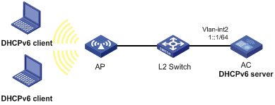
Configuration procedure
# Configure basic settings on the AC. For more information, see WLAN Configuration Guide.
# Specify an IPv6 address for VLAN-interface 2.
<AC> system-view
[AC] interface vlan-interface 2
[AC-Vlan-interface2] ipv6 address 1::1/64
# Disable RA message suppression on VLAN-interface 2.
[AC-Vlan-interface2] undo ipv6 nd ra halt
# Set the M flag to 1 in RA advertisements to be sent on VLAN-interface 2. Hosts that receive the RA advertisements will obtain IPv6 addresses through DHCPv6.
[AC-Vlan-interface2] ipv6 nd autoconfig managed-address-flag
# Set the O flag to 1 in RA advertisements to be sent on VLAN-interface 2. Hosts that receive the RA advertisements will obtain information other than IPv6 address through DHCPv6.
[AC-Vlan-interface2] ipv6 nd autoconfig other-flag
[AC-Vlan-interface2] quit
# Create prefix pool 1, and specify the prefix 2001:0410::/32 with the assigned prefix length 48.
[AC] ipv6 dhcp prefix-pool 1 prefix 2001:0410::/32 assign-len 48
# Create address pool 1.
[AC] ipv6 dhcp pool 1
# In address pool 1, configure subnet 1::/64 where VLAN interface-2 resides.
[AC-dhcp6-pool-1] network 1::/64
# Apply prefix pool 1 to address pool 1, and set the preferred lifetime to one day, and the valid lifetime to three days.
[AC-dhcp6-pool-1] prefix-pool 1 preferred-lifetime 86400 valid-lifetime 259200
# In address pool 1, bind prefix 2001:0410:0201::/48 to the client DUID 00030001CA0006A40000, and set the preferred lifetime to one day, and the valid lifetime to three days.
[AC-dhcp6-pool-1] static-bind prefix 2001:0410:0201::/48 duid 00030001CA0006A40000 preferred-lifetime 86400 valid-lifetime 259200
# Configure the DNS server address 2:2::3.
[AC-dhcp6-pool-1] dns-server 2:2::3
# Configure the domain name as aaa.com.
[AC-dhcp6-pool-1] domain-name aaa.com
# Configure the SIP server address as 2:2::4, and the SIP server name as bbb.com.
[AC-dhcp6-pool-1] sip-server address 2:2::4
[AC-dhcp6-pool-1] sip-server domain-name bbb.com
[AC-dhcp6-pool-1] quit
# Enable the DHCPv6 server on VLAN-interface 2, enable desired prefix assignment and rapid prefix assignment, and set the preference to the highest.
[AC] interface vlan-interface 2
[AC-Vlan-interface2] ipv6 dhcp select server
[AC-Vlan-interface2] ipv6 dhcp server allow-hint preference 255 rapid-commit
Verifying the configuration
# Display DHCPv6 server configuration on VLAN-interface 2.
[AC-Vlan-interface2] display ipv6 dhcp server interface vlan-interface 2
Using pool: global
Preference value: 255
Allow-hint: Enabled
Rapid-commit: Enabled
# Display information about address pool 1.
[AC-Vlan-interface2] display ipv6 dhcp pool 1
DHCPv6 pool: 1
Network: 1::/64
Preferred lifetime 604800, valid lifetime 2592000
Prefix pool: 1
Preferred lifetime 86400, valid lifetime 259200
Static bindings:
DUID: 00030001ca0006a40000
IAID: Not configured
Prefix: 2001:410:201::/48
Preferred lifetime 86400, valid lifetime 259200
DNS server addresses:
2:2::3
Domain name:
aaa.com
SIP server addresses:
2:2::4
SIP server domain names:
bbb.com
# Display information about prefix pool 1.
[AC-Vlan-interface2] display ipv6 dhcp prefix-pool 1
Prefix: 2001:410::/32
Assigned length: 48
Total prefix number: 65536
Available: 65535
In-use: 0
Static: 1
# After the client with the DUID 00030001CA0006A40000 obtains an IPv6 prefix, display the binding information on the DHCPv6 server.
[AC-Vlan-interface2] display ipv6 dhcp server pd-in-use
Pool: 1
IPv6 prefix Type Lease expiration
2001:410:201::/48 Static(C) Jul 10 19:45:01 2009
# After the other client obtains an IPv6 prefix, display binding information on the DHCPv6 server.
[AC-Vlan-interface2] display ipv6 dhcp server pd-in-use
Pool: 1
IPv6 prefix Type Lease expiration
2001:410:201::/48 Static(C) Jul 10 19:45:01 2009
2001:410::/48 Auto(C) Jul 10 20:44:05 2009
Dynamic IPv6 address assignment configuration example
Network requirements
As shown in Figure 70, the AC acts as a DHCPv6 server to assign IPv6 addresses to the AP and DHCPv6 clients. The DHCPv6 server assigns an IPv6 address on subnet 1::1:0:0:0/96 to the AP and assigns IPv6 addresses on subnet 1::2:0:0:0/96 to the DHCPv6 clients.
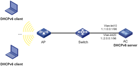
Configuration procedure
1. Configure the interfaces on the DHCPv6 server:
# Specify an IPv6 address for VLAN-interface 10.
<AC> system-view
[AC] vlan 10
[AC-vlan10] quit
[AC] interface vlan-interface 10
[AC-Vlan-interface10] ipv6 address 1::1:0:0:1/96
# Disable RA message suppression on VLAN-interface 10.
[AC-Vlan-interface10] undo ipv6 nd ra halt
# Set the M flag to 1 in RA advertisements to be sent on VLAN-interface 10. Hosts that receive the RA advertisements will obtain IPv6 addresses through DHCPv6.
[AC-Vlan-interface10] ipv6 nd autoconfig managed-address-flag
# Set the O flag to 1 in RA advertisements to be sent on VLAN-interface 10. Hosts that receive the RA advertisements will obtain information other than IPv6 address through DHCPv6.
[AC-Vlan-interface10] ipv6 nd autoconfig other-flag
[AC-Vlan-interface10] quit
# Specify an IPv6 address for VLAN-interface 20.
[AC] vlan 20
[AC-vlan20] quit
[AC] interface vlan-interface 20
[AC-Vlan-interface20] ipv6 address 1::2:0:0:1/96
# Disable RA message suppression on VLAN-interface 20.
[AC-Vlan-interface20] undo ipv6 nd ra halt
# Set the M flag to 1 in RA advertisements to be sent on VLAN-interface 20. Hosts that receive the RA advertisements will obtain IPv6 addresses through DHCPv6.
[AC-Vlan-interface20] ipv6 nd autoconfig managed-address-flag
# Set the O flag to 1 in RA advertisements to be sent on VLAN-interface 20. Hosts that receive the RA advertisements will obtain information other than IPv6 address through DHCPv6.
[AC-Vlan-interface20] ipv6 nd autoconfig other-flag
[AC-Vlan-interface20] quit
2. Add the interface connected to the AP to VLAN 10.
[AC] interface gigabitethernet 1/0/2
[AC-GigabitEthernet1/0/2] port link-type trunk
[AC-GigabitEthernet1/0/2] port trunk permit vlan 10
[AC-GigabitEthernet1/0/2] port trunk pvid vlan 10
[AC-GigabitEthernet1/0/2] quit
3. Configure wireless services:
# Configure a service template and bind VLAN 20 to the service template.
[AC] wlan service-template service
[AC-wlan-st-service] ssid service
[AC-wlan-st-service] vlan 20
[AC-wlan-st-service] service-template enable
[AC-wlan-st-service] quit
# Configure the AP.
[AC] wlan ap ap1 model WA536
[AC-wlan-ap-ap1] serial-id 219801A1NQB117012935
[AC-wlan-ap-ap1] radio 1
[AC-wlan-ap-ap1-radio-1] service-template service1
[AC-wlan-ap-ap1-radio-1] radio enable
[AC-wlan-ap-ap1-radio-1] return
4. Enable DHCPv6:
# Enable DHCPv6 server on VLAN-interface 10 and VLAN-interface 20.
[AC] interface vlan-interface 10
[AC-Vlan-interface10] ipv6 dhcp select server
[AC-Vlan-interface10] quit
[AC] interface vlan-interface 20
[AC-Vlan-interface20] ipv6 dhcp select server
[AC-Vlan-interface20] quit
# Configure the DHCPv6 address pool 1 to assign IPv6 addresses to the AP on subnet 1::1:0:0:0/96.
[AC] ipv6 dhcp pool 1
[AC-dhcp6-pool-1] network 1::1:0:0:0/96
[AC-dhcp6-pool-1] quit
# Configure the DHCPv6 address pool 2 to assign IPv6 addresses to clients on subnet 1::2:0:0:0/96.
[AC] ipv6 dhcp pool 2
[AC-dhcp6-pool-2] network 1::2:0:0:0/96
[AC-dhcp6-pool-2] quit
Verifying the configuration
# Verify that the AP on subnet 1::1:0:0:0/96 and the DHCPv6 clients on subnet 1::2:0:0:0/96 can obtain IPv6 addresses from the DHCPv6 server. (Details not shown.)
# On the DHCPv6 server, display IPv6 addresses assigned to the AP and DHCPv6 clients.
[AC] display ipv6 dhcp server ip-in-use
Configuring the DHCPv6 relay agent
Overview
A DHCPv6 client usually uses a multicast address to contact the DHCPv6 server on the local link to obtain an IPv6 address and other configuration parameters. As shown in Figure 71, if the DHCPv6 server resides on another subnet, the DHCPv6 clients need a DHCPv6 relay agent to contact the server. The relay agent feature avoids deploying a DHCP server on each subnet.
Figure 71 Typical DHCPv6 relay agent application
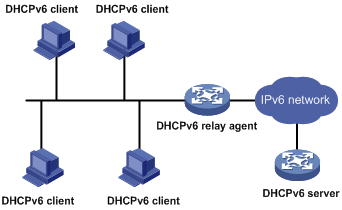
As shown in Figure 72, a DHCPv6 client obtains an IPv6 address and other network configuration parameters from a DHCPv6 server through a DHCPv6 relay agent. The following example uses rapid assignment to describe the process:
· The DHCPv6 client sends a Solicit message containing the Rapid Commit option to the multicast address FF02::1:2 of all the DHCPv6 servers and relay agents.
· After receiving the Solicit message, the DHCPv6 relay agent encapsulates the message into the Relay Message option of a Relay-forward message, and sends the message to the DHCPv6 server.
· After obtaining the Solicit message from the Relay-forward message, the DHCPv6 server performs the following tasks:
? Selects an IPv6 address and other required parameters.
? Adds them to a reply that is encapsulated within the Relay Message option of a Relay-reply message.
? Sends the Relay-reply message to the DHCPv6 relay agent.
· The DHCPv6 relay agent obtains the reply from the Relay-reply message and sends the reply to the DHCPv6 client.
· The DHCPv6 client uses the IPv6 address and other network parameters assigned by the DHCPv6 server to complete network configuration.
Figure 72 Operating process of a DHCPv6 relay agent
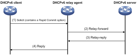
DHCPv6 relay agent configuration task list
|
Tasks at a glance |
|
(Required.) Enabling the DHCPv6 relay agent on an interface |
|
(Required.) Specifying DHCPv6 servers on the relay agent |
|
(Optional.) Setting the DSCP value for DHCPv6 packets sent by the DHCPv6 relay agent |
|
(Optional.) Specifying a padding mode for the Interface-ID option |
|
(Optional.) Configuring a DHCPv6 relay address pool |
|
(Optional.) Specifying a gateway address for DHCPv6 clients |
Enabling the DHCPv6 relay agent on an interface
|
Step |
Command |
Remarks |
|
1. Enter system view. |
system-view |
N/A |
|
2. Enter interface view. |
interface interface-type interface-number |
N/A |
|
3. Enable DHCPv6 relay agent on the interface. |
ipv6 dhcp select relay |
By default, the DHCPv6 relay agent is disabled on the interface. Do not enable the DHCPv6 relay agent and DHCPv6 client on the same interface. |
Specifying DHCPv6 servers on the relay agent
You can use the ipv6 dhcp relay server-address command to specify a maximum of eight DHCPv6 servers on the DHCP relay agent interface. The DHCPv6 relay agent forwards DHCP requests to all the specified DHCPv6 servers.
To specify a DHCPv6 server on a relay agent:
|
Step |
Command |
Remarks |
|
1. Enter system view. |
system-view |
N/A |
|
2. Enter interface view. |
interface interface-type interface-number |
N/A |
|
3. Specify a DHCPv6 server. |
ipv6 dhcp relay server-address ipv6-address [ interface interface-type interface-number ] |
By default, no DHCPv6 server is specified. If a DHCPv6 server address is a link-local address or multicast address, you must specify an outgoing interface by using the interface keyword in this command. Otherwise, DHCPv6 packets might fail to reach the DHCPv6 server. |
Setting the DSCP value for DHCPv6 packets sent by the DHCPv6 relay agent
The DSCP value of a packet specifies the priority level of the packet and affects the transmission priority of the packet.
To set the DSCP value for DHCPv6 packets sent by the DHCPv6 relay agent:
|
Step |
Command |
Remarks |
|
1. Enter system view. |
system-view |
N/A |
|
2. Set the DSCP value for DHCPv6 packets sent by the DHCPv6 relay agent. |
ipv6 dhcp dscp dscp-value |
The default DSCP value is 56. |
Specifying a padding mode for the Interface-ID option
This feature enables the relay agent to fill the Interface-ID option in the specified mode. When receiving a DHCPv6 packet from a client, the relay agent fills the Interface-ID option in the mode and then forwards the packet to the DHCPv6 server.
To specify a padding mode for the Interface-ID option:
|
Step |
Command |
Remarks |
|
1. Enter system view. |
system-view |
N/A |
|
2. Enter interface view. |
interface interface-type interface-number |
N/A |
|
3. Specify a padding mode for the Interface-ID option. |
ipv6 dhcp relay interface-id { bas | interface } |
By default, the relay agent fills the Interface-ID option with the interface index of the interface. |
Configuring a DHCPv6 relay address pool
This feature allows DHCPv6 clients of the same type to obtain IPv6 addresses and other configuration parameters from the DHCPv6 servers specified in the matching relay address pool.
It applies to scenarios where the DHCPv6 relay agent connects to clients of the same access type but classified into different types by their locations. In this case, the relay interface typically has no IPv6 address configured. You can use the gateway-list command to specify the gateway address for clients matching the same relay address pool.
Upon receiving a DHCPv6 Solicit or Request from a client that matches a relay address pool, the relay agent processes the packet as follows:
· Fills the link-address field of the packet with the specified gateway address.
· Forwards the packet to all DHCPv6 servers in the matching relay address pool.
The DHCPv6 servers select an address pool according to the gateway address.
To configure a DHCPv6 relay address pool:
|
Step |
Command |
Remarks |
|
1. Enter system view. |
system-view |
N/A |
|
2. Create a DHCPv6 relay address pool and enter its view. |
ipv6 dhcp pool pool-name |
By default, no DHCPv6 relay address pool exists. This command is the same for creating DHCPv6 address pools on a DHCPv6 server. However, the relay address pool name is not necessarily the same as the server address pool name. |
|
3. Specify gateway addresses for the clients matching the relay address pool. |
gateway-list ipv6-address&<1-8> |
By default, no gateway address is specified. You can specify a maximum of eight gateway addresses, but only the first one takes effect. |
|
4. Specify DHCPv6 servers for the relay address pool. |
remote-server ipv6-address [ interface interface-type interface-number ] |
By default, no DHCPv6 server is specified for the relay address pool. You can specify a maximum of eight DHCPv6 servers for one relay address pool for high availability. The relay agent forwards DHCPv6 Solicit and Request packets to all DHCPv6 servers in the relay address pool. |
Specifying a gateway address for DHCPv6 clients
By default, the DHCPv6 relay agent fills the link-address field of DHCPv6 Solicit and Request packets with the first IPv6 address of the relay interface. You can specify a gateway address on the relay agent for DHCPv6 clients. The DHCPv6 relay agent uses the specified gateway address to fill the link-address field of DHCPv6 Solicit and Request packets.
To specify a gateway address for DHCPv6 clients:
|
Step |
Command |
Remarks |
|
1. Enter system view. |
system-view |
N/A |
|
2. Enter interface view. |
interface interface-type interface-number |
N/A |
|
3. Specify a gateway address for DHCPv6 clients. |
ipv6 dhcp relay gateway ipv6-address |
By default, the DHCPv6 relay agent uses the first IPv6 address of the relay interface as the clients' gateway address. |
Displaying and maintaining the DHCPv6 relay agent
Execute display commands in any view and reset commands in user view.
|
Task |
Command |
|
Display the DUID of the local device. |
display ipv6 dhcp duid |
|
Display DHCPv6 server addresses specified on the DHCPv6 relay agent. |
display ipv6 dhcp relay server-address [ interface interface-type interface-number ] |
|
Display packet statistics on the DHCPv6 relay agent. |
display ipv6 dhcp relay statistics [ interface interface-type interface-number ] |
|
Clear packets statistics on the DHCPv6 relay agent. |
reset ipv6 dhcp relay statistics [ interface interface-type interface-number ] |
DHCPv6 relay agent configuration example
Network requirements
As shown in Figure 73, configure the DHCPv6 relay agent on the AC to relay DHCPv6 packets between DHCPv6 clients and the DHCPv6 server.
The AC acts as the gateway of network 1::/64. It sends RA messages to notify the hosts to obtain IPv6 addresses and other configuration parameters through DHCPv6. For more information about RA messages, see "Configuring basic IPv6 settings."
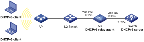
Configuration procedure
# Configure basic settings on the AC. For more information, see WLAN Configuration Guide.
# Specify IPv6 addresses for VLAN-interface 2 and VLAN-interface 3.
<AC> system-view
[AC] interface vlan-interface 2
[AC-Vlan-interface2] ipv6 address 2::1 64
[AC-Vlan-interface2] quit
[AC] interface vlan-interface 3
[AC-Vlan-interface3] ipv6 address 1::1 64
# Disable RA message suppression on VLAN-interface 3.
[AC-Vlan-interface3] undo ipv6 nd ra halt
# Set the M flag to 1 in RA advertisements to be sent on VLAN-interface 3. Hosts that receive the RA advertisements will obtain IPv6 addresses through DHCPv6.
[AC-Vlan-interface3] ipv6 nd autoconfig managed-address-flag
# Set the O flag to 1 in RA advertisements to be sent on VLAN-interface 3. Hosts that receive the RA advertisements will obtain information other than IPv6 address through DHCPv6.
[AC-Vlan-interface3] ipv6 nd autoconfig other-flag
# Enable the DHCPv6 relay agent on VLAN-interface 3 and specify the DHCPv6 server on the relay agent.
[AC-Vlan-interface3] ipv6 dhcp select relay
[AC-Vlan-interface3] ipv6 dhcp relay server-address 2::2
Verifying the configuration
# Display DHCPv6 server address information on the DHCPv6 relay agent.
[AC-Vlan-interface3] display ipv6 dhcp relay server-address
Interface: Vlan-interface3
Server address Outgoing Interface
2::2
# Display packet statistics on the DHCPv6 relay agent.
[AC-Vlan-interface3] display ipv6 dhcp relay statistics
Packets dropped : 0
Packets received : 14
Solicit : 0
Request : 0
Confirm : 0
Renew : 0
Rebind : 0
Release : 0
Decline : 0
Information-request : 7
Relay-forward : 0
Relay-reply : 7
Packets sent : 14
Advertise : 0
Reconfigure : 0
Reply : 7
Relay-forward : 7
Relay-reply : 0
Configuring the DHCPv6 client
Overview
With DHCPv6 client configured, an interface can obtain configuration parameters from the DHCPv6 server.
A DHCPv6 client can use DHCPv6 to complete the following functions:
· Obtain an IPv6 address, an IPv6 prefix, or both, and obtain other configuration parameters. The client automatically creates a DHCPv6 option group for the obtained parameters. With the obtained IPv6 prefix, the client can generate its global unicast address.
· Support stateless DHCPv6 to obtain configuration parameters except IPv6 address and IPv6 prefix. The client obtains an IPv6 address through stateless IPv6 address autoconfiguration. If the client receives an RA message with the M flag set to 0 and the O flag set to 1 during address acquisition, stateless DHCPv6 starts.
Configuration restrictions and guidelines
When you configure DHCPv6 client, follow these restrictions and guidelines:
· The DHCPv6 client configuration is supported only on Layer 3 Ethernet interfaces, Layer 3 aggregate interfaces, and VLAN interfaces.
· Do not configure the DHCPv6 client on the same interface as the DHCPv6 server or the DHCPv6 relay agent.
DHCPv6 client configuration task list
|
Tasks at a glance |
|
(Required.) Perform one of the following tasks: · Configuring IPv6 address acquisition · Configuring IPv6 prefix acquisition |
|
(Optional.) Configuring the DHCPv6 client DUID |
|
(Optional.) Setting the DSCP value for DHCPv6 packets sent by the DHCPv6 client |
Configuring IPv6 address acquisition
|
Step |
Command |
Remarks |
|
1. Enter system view. |
system-view |
N/A |
|
2. Enter interface view. |
interface interface-type interface-number |
Supported interfaces include Layer 3 Ethernet interface, Layer 3 Ethernet subinterface, and VLAN interface. |
|
3. Configure the interface to use DHCPv6 to obtain an IPv6 address and other configuration parameters. |
ipv6 address dhcp-alloc [ option-group group-number | rapid-commit ] * |
By default, the interface does not use DHCPv6 for IPv6 address acquisition. |
Configuring IPv6 prefix acquisition
|
Step |
Command |
Remarks |
|
1. Enter system view. |
system-view |
N/A |
|
2. Enter interface view. |
interface interface-type interface-number |
Supported interfaces include Layer 3 Ethernet interface, Layer 3 Ethernet subinterface, and VLAN interface. |
|
3. Configure the interface to use DHCPv6 to obtain an IPv6 prefix and other configuration parameters. |
ipv6 dhcp client pd prefix-number [ option-group group-number | rapid-commit ] * |
By default, the interface does not use DHCPv6 for IPv6 prefix acquisition. |
Configuring IPv6 address and prefix acquisition
|
Step |
Command |
Remarks |
|
1. Enter system view. |
system-view |
N/A |
|
2. Enter interface view. |
interface interface-type interface-number |
Supported interfaces include Layer 3 Ethernet interface, Layer 3 Ethernet subinterface, and VLAN interface. |
|
3. Configure the interface to use DHCPv6 to obtain an IPv6 address, an IPv6 prefix, and other configuration parameters. |
ipv6 dhcp client stateful prefix prefix-number [ option-group option-group-number | rapid-commit ] * |
By default, the interface does not use DHCPv6 for IPv6 address and prefix acquisition. |
Configuring stateless DHCPv6
|
Step |
Command |
Remarks |
|
1. Enter system view. |
system-view |
N/A |
|
2. Enter interface view. |
interface interface-type interface-number |
Supported interfaces include Layer 3 Ethernet interface, Layer 3 Ethernet subinterface, and VLAN interface. |
|
3. Configure the interface to support stateless DHCPv6. |
· Enable stateless IPv6 address
autoconfiguration: · Enable stateless DHCPv6: |
By default, the interface does not support stateless DHCPv6. You can perform both tasks. If you use only the ipv6 address auto command, make sure the M flag is set to 0 and the O flag is set to 1 in the RA message. Otherwise, stateless DHCPv6 cannot be triggered. |
Configuring the DHCPv6 client DUID
The DUID of a DHCPv6 client is the globally unique identifier of the client. Make sure the DUID that you configure is unique. The client pads its DUID into Option 1 of the DHCPv6 packet that it sends to the DHCPv6 server. The DHCPv6 server can assign specific IPv6 addresses or prefixes to DHCPv6 clients with specific DUIDs.
To configure the DHCPv6 client DUID:
|
Step |
Command |
Remarks |
|
1. Enter system view. |
system-view |
N/A |
|
2. Enter interface view. |
interface interface-type interface-number |
Supported interfaces include Layer 3 Ethernet interface, Layer 3 Ethernet subinterface, and VLAN interface. |
|
3. Configure the DHCPv6 client DUID. |
ipv6 dhcp client duid { ascii string | hex string | mac interface-type interface-number } |
By default, the interface uses the device bridge MAC address to generate its DHCPv6 client DUID. |
Setting the DSCP value for DHCPv6 packets sent by the DHCPv6 client
The DSCP value of a packet specifies the priority level of the packet and affects the transmission priority of the packet.
To set the DSCP value for DHCPv6 packets sent by the DHCPv6 client:
|
Step |
Command |
Remarks |
|
1. Enter system view. |
system-view |
N/A |
|
2. Set the DSCP value for DHCPv6 packets sent by the DHCPv6 client. |
ipv6 dhcp client dscp dscp-value |
By default, the DSCP value in DHCPv6 packets sent by the DHCPv6 client is 56. |
Displaying and maintaining DHCPv6 client
Execute the display commands in any view, and execute the reset command in user view.
|
Task |
Command |
|
Display the DHCPv6 client information. |
display ipv6 dhcp client [ interface interface-type interface-number ] |
|
Display the DHCPv6 client statistics. |
display ipv6 dhcp client statistics [ interface interface-type interface-number ] |
|
Clear the DHCPv6 client statistics. |
reset ipv6 dhcp client statistics [ interface interface-type interface-number ] |
Configuring DHCPv6 snooping
Overview
DHCPv6 snooping works between the DHCPv6 client and server, or between the DHCPv6 client and DHCPv6 relay agent. It guarantees that DHCPv6 clients obtain IP addresses from authorized DHCPv6 servers. Also, it records IP-to-MAC bindings of DHCPv6 clients (called DHCPv6 snooping entries) for security purposes.
DHCPv6 snooping does not work between the DHCPv6 server and DHCPv6 relay agent.
DHCPv6 snooping defines trusted and untrusted ports to make sure that clients obtain IPv6 addresses only from authorized DHCPv6 servers.
· Trusted—A trusted port can forward DHCPv6 messages correctly to make sure the clients get IPv6 addresses from authorized DHCPv6 servers.
· Untrusted—An untrusted port discards received messages sent by DHCPv6 servers to prevent unauthorized servers from assigning IPv6 addresses.
DHCPv6 snooping reads DHCP-ACK messages received from trusted ports and DHCP-REQUEST messages to create DHCPv6 snooping entries. A DHCPv6 snooping entry includes the MAC and IP addresses of a client, the port that connects to the DHCPv6 client, and the VLAN. You can use the display ipv6 dhcp snooping binding command to display the IP addresses of users for management.
Application of trusted and untrusted ports
Configure ports facing the DHCPv6 server as trusted ports, and configure other ports as untrusted ports.
As shown in Figure 74, configure the DHCPv6 snooping device's port that is connected to the DHCPv6 server as a trusted port. The trusted port forwards response messages from the DHCPv6 server to the client. The untrusted port connected to the unauthorized DHCPv6 server discards incoming DHCPv6 response messages.
Figure 74 Trusted and untrusted ports
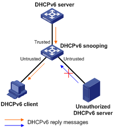
Command and hardware compatibility
The WX1800H series access controllers do not support the slot keyword or the slot-number argument.
H3C implementation of Option 18 and Option 37
Option 18 for DHCPv6 snooping
Option 18, also called the interface-ID option, is used by the DHCPv6 relay agent to determine the interface to use to forward RELAY-REPLY message.
In H3C implementation, the DHCPv6 snooping device adds Option 18 to the received DHCPv6 request message before forwarding it to the DHCPv6 server. The server then assigns IP address to the client based on the client information in Option 18.
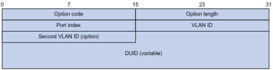
Figure 75 shows the Option 18 format, which includes the following fields:
· Option code—Option code.
· Option length—Size of the option data.
· Port index—Port that receives the DHCPv6 request from the client.
· VLAN ID—ID of the outer VLAN.
· Second VLAN ID—ID of the inner VLAN.
· DUID—DUID of the DHCPv6 client.
|
|
NOTE: The Second VLAN ID field is optional. If the received DHCPv6 request does not contain a second VLAN, Option 18 also does not contain it. |
DHCPv6 snooping support for Option 37
Option 37, also called the remote-ID option, is used to identify the client.
In H3C implementation, the DHCPv6 snooping device adds Option 37 to the received DHCPv6 request message before forwarding it to the DHCPv6 server. This option provides client information about address allocation.
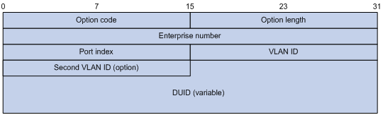
Figure 76 shows the Option 37 format, which includes the following fields:
· Option code—Option code.
· Option length—Size of the option data.
· Enterprise number—Enterprise number.
· Port index—Port that receives the DHCPv6 request from the client.
· VLAN ID—ID of the outer VLAN.
· Second VLAN ID—ID of the inner VLAN.
· DUID—DUID of the DHCPv6 client.
|
|
NOTE: The Second VLAN ID field is optional. If the received DHCPv6 request does not contain a second VLAN, Option 37 also does not contain it. |
DHCPv6 snooping configuration task list
|
Tasks at a glance |
|
(Required.) Configuring basic DHCPv6 snooping |
|
(Optional.) Configuring Option 18 and Option 37 |
|
(Optional.) Configuring DHCPv6 snooping entry auto backup |
|
(Optional.) Setting the maximum number of DHCPv6 snooping entries |
|
(Optional. ) Configuring DHCPv6 packet rate limit |
|
(Optional.) Enabling DHCPv6-REQUEST check |
|
(Optional.) Configuring a DHCPv6 packet blocking port |
|
(Optional.) Enabling DHCPv6 snooping logging |
Configuring basic DHCPv6 snooping
Follow these guidelines when you configure basic DHCPv6 snooping:
· To make sure DHCPv6 clients can obtain valid IPv6 addresses, specify the ports connected to authorized DHCPv6 servers as trusted ports. The trusted ports and the ports connected to DHCPv6 clients must be in the same VLAN.
· If you configure DHCPv6 snooping settings on a Layer 2 Ethernet interface that is a member port of a Layer 2 aggregate interface, the settings do not take effect unless the interface is removed from the aggregation group.
To configure basic DHCPv6 snooping:
|
Step |
Command |
Remarks |
|
1. Enter system view. |
system-view |
N/A |
|
2. Enable DHCPv6 snooping. |
ipv6 dhcp snooping enable |
By default, DHCPv6 snooping is disabled. |
|
3. Enter interface view. |
interface interface-type interface-number |
This interface must connect to the DHCPv6 server. |
|
4. Specify the port as a trusted port. |
ipv6 dhcp snooping trust |
By default, all ports are untrusted ports after DHCPv6 snooping is enabled. |
|
5. Return to system view. |
quit |
N/A |
|
6. Enter interface view. |
interface interface-type interface-number |
This interface must connect to the DHCPv6 client. |
|
7. (Optional.) Enable recording of client information in DHCPv6 snooping entries. |
ipv6 dhcp snooping binding record |
By default, DHCPv6 snooping does not record client information. |
Configuring Option 18 and Option 37
|
Step |
Command |
Remarks |
|
1. Enter system view. |
system-view |
N/A |
|
2. Enter interface view. |
interface interface-type interface-number |
N/A |
|
3. Enable support for Option 18. |
ipv6 dhcp snooping option interface-id enable |
By default, Option 18 is not supported. |
|
4. (Optional.) Specify the content as the interface ID. |
ipv6 dhcp snooping option interface-id [ vlan vlan-id ] string interface-id |
By default, the DHCPv6 snooping device uses its DUID as the content for Option 18. |
|
5. Enable support for Option 37. |
ipv6 dhcp snooping option remote-id enable |
By default, Option 37 is not supported. |
|
6. (Optional.) Specify the content as the remote ID. |
ipv6 dhcp snooping option remote-id [ vlan vlan-id ] string remote-id |
By default, the DHCPv6 snooping device uses its DUID as the content for Option 37. |
Configuring DHCPv6 snooping entry auto backup
The auto backup feature saves DHCPv6 snooping entries to a backup file, and allows the DHCPv6 snooping device to download the entries from the backup file at reboot. The entries on the DHCPv6 snooping device cannot survive a reboot. The auto backup helps the security features provide services if these features (such as IP source guard) must use DHCPv6 snooping entries for user authentication.
|
|
IMPORTANT: If you disable DHCPv6 snooping with the undo ipv6 dhcp snooping enable command, the device deletes all DHCPv6 snooping entries, including those stored in the backup file. |
To configure DHCPv6 snooping entry auto backup:
|
Step |
Command |
Remarks |
|
1. Enter system view. |
system-view |
N/A |
|
2. Configure the DHCPv6 snooping device to back up DHCPv6 snooping entries to a file. |
ipv6 dhcp snooping binding database filename { filename | url url [ username username [ password { cipher | simple } string ] ] } |
By default, the DHCPv6 snooping device does not back up the DHCPv6 snooping entries. With this command executed, the DHCPv6 snooping device backs up DHCPv6 snooping entries immediately and runs auto backup. This command automatically creates the file if you specify a non-existent file. |
|
3. (Optional.) Manually save DHCPv6 snooping entries to the backup file. |
ipv6 dhcp snooping binding database update now |
N/A |
|
4. (Optional.) Set the waiting time after a DHCPv6 snooping entry change for the DHCPv6 snooping device to update the backup file. |
ipv6 dhcp snooping binding database update interval interval |
The default waiting time is 300 seconds. The waiting period starts when a DHCPv6 snooping entry is learned, updated, or removed. The DHCPv6 snooping device updates the backup file when the specified waiting period is reached. All changed entries during the period will be saved to the backup file. If no DHCPv6 snooping entry changes, the backup file is not updated. |
Setting the maximum number of DHCPv6 snooping entries
Perform this task to prevent the system resources from being overused.
To set the maximum number of DHCPv6 snooping entries:
|
Step |
Command |
Remarks |
|
1. Enter system view. |
system-view |
N/A |
|
2. Enter interface view. |
interface interface-type interface-number |
N/A |
|
3. Set the maximum number of DHCPv6 snooping entries for the interface to learn. |
ipv6 dhcp snooping max-learning-num max-number |
By default, the number of DHCPv6 snooping entries for an interface to learn is not limited. |
Enabling DHCPv6-REQUEST check
Perform this task to use the DHCPv6-REQUEST check feature to protect the DHCPv6 server against DHCPv6 client spoofing attacks. Attackers can forge DHCPv6-RENEW messages to renew leases for legitimate DHCPv6 clients that no longer need the IP addresses. The forged messages disable the victim DHCPv6 server from releasing the IP addresses. Attackers can also forge DHCPv6-DECLINE or DHCPv6-RELEASE messages to terminate leases for legitimate DHCPv6 clients that still need the IP addresses.
The DHCPv6-REQUEST check feature enables the DHCPv6 snooping device to check every received DHCPv6-RENEW, DHCPv6-DECLINE, or DHCPv6-RELEASE message against DHCPv6 snooping entries.
· If any criterion in an entry is matched, the device compares the entry with the message information.
? If they are consistent, the device considers the message valid and forwards it to the DHCPv6 server.
? If they are different, the device considers the message forged and discards it.
· If no matching entry is found, the device forwards the message to the DHCPv6 server.
To enable DHCPv6-REQUEST check:
|
Step |
Command |
Remarks |
|
1. Enter system view. |
system-view |
N/A |
|
2. Enter interface view. |
interface interface-type interface-number |
N/A |
|
ipv6 dhcp snooping check request-message |
By default, DHCPv6-REQUEST check is disabled. You can enable the feature only on Layer 2 Ethernet interfaces, and Layer 2 aggregate interfaces. |
Configuring DHCPv6 packet rate limit
This DHCPv6 packet rate limit feature discards exceeding DHCPv6 packets to prevent attacks that send large numbers of DHCPv6 packets.
To configure DHCPv6 packet rate limit:
|
Step |
Command |
Remarks |
|
1. Enter system view. |
system-view |
N/A |
|
2. Enter interface view. |
interface interface-type interface-number |
N/A |
|
3. Set the maximum rate at which an interface can receive DHCPv6 packets. |
ipv6 dhcp snooping rate-limit rate |
By default, incoming DHCPv6 packets on an interface are not rate limited. You can configure this command only on Layer 2 Ethernet interfaces and Layer 2 aggregate interfaces. If you set the maximum rate on a Layer 2 Ethernet interface that is a member port of a Layer 2 aggregate interface, the Layer 2 Ethernet interface uses the DHCP packet maximum rate set on the Layer 2 aggregate interface. If the Layer 2 Ethernet interface leaves the aggregation group, it uses its own DHCP packet maximum rate. |
Configuring a DHCPv6 packet blocking port
Perform this task to configure a port as a DHCPv6 packet blocking port. The DHCPv6 packet blocking port drops all incoming DHCP requests.
To configure a DHCPv6 packet blocking port:
|
Step |
Command |
Remarks |
|
1. Enter system view. |
system-view |
N/A |
|
2. Enter interface view. |
interface interface-type interface-number |
N/A |
|
3. Configure the port to block DHCPv6 requests. |
ipv6 dhcp snooping deny |
By default, the port does not block DHCPv6 requests. |
Enabling DHCPv6 snooping logging
The DHCPv6 snooping logging feature enables the DHCPv6 snooping device to generate DHCPv6 snooping logs and send them to the information center. For information about the log destination and output rule configuration in the information center, see Network Management and Monitoring Configuration Guide.
As a best practice, disable this feature if the log generation affects the device performance.
To enable DHCPv6 snooping logging:
|
Step |
Command |
Remarks |
|
1. Enter system view. |
system-view |
N/A |
|
2. Enable DHCPv6 snooping logging. |
ipv6 dhcp snooping log enable |
By default, DHCPv6 snooping logging is disabled. |
Displaying and maintaining DHCPv6 snooping
Execute display commands in any view, and reset commands in user view.
|
Task |
Command |
|
Display information about trusted ports. |
display ipv6 dhcp snooping trust |
|
Display DHCPv6 snooping entries. |
display ipv6 dhcp snooping binding [ address ipv6-address [ vlan vlan-id ] ] |
|
Display information about the file that stores DHCPv6 snooping entries. |
display ipv6 dhcp snooping binding database |
|
Display DHCPv6 packet statistics for DHCPv6 snooping. |
display ipv6 dhcp snooping packet statistics [ slot slot-number ] |
|
Clear DHCPv6 snooping entries. |
reset ipv6 dhcp snooping binding { all | address ipv6-address [ vlan vlan-id ] } |
|
Clear DHCPv6 packet statistics for DHCPv6 snooping. |
reset ipv6 dhcp snooping packet statistics [ slot slot-number ] |
DHCPv6 snooping configuration example
Network requirements
As shown in Figure 77, configure GigabitEthernet 1/0/1 connected to the DHCPv6 server as a trusted port. Enable DHCPv6 snooping to record clients' IP-to-MAC bindings in DHCPv6 snooping entries.
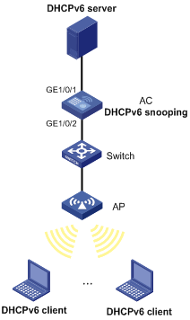
Configuration procedure
# Configure WLAN access on the AC. For more information about WLAN access configuration, see WLAN Configuration Guide. (Details not shown.)
# Enable DHCPv6 snooping.
<AC> system-view
[AC] ipv6 dhcp snooping enable
# Specify GigabitEthernet 1/0/1 as a trusted port.
[AC] interface gigabitethernet 1/0/1
[AC-GigabitEthernet1/0/1] ipv6 dhcp snooping trust
[AC-GigabitEthernet1/0/1] quit
# Enable recording of client information in DHCPv6 snooping entries.
[AC]interface gigabitethernet 1/0/2
[AC-GigabitEthernet1/0/2] ipv6 dhcp snooping binding record
[AC-GigabitEthernet1/0/2] quit
Verifying the configuration
# Verify that the DHCPv6 client obtains an IPv6 address and all other configuration parameters only from the DHCPv6 server. (Details not shown.)
# Display DHCPv6 snooping entries on the DHCPv6 snooping device.
[AC] display ipv6 dhcp snooping binding
Configuring GRE
Overview
GRE encapsulation format
Figure 78 GRE encapsulation format
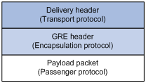
As shown in Figure 78, a GRE-tunneled packet includes the following parts:
· Payload packet—Original packet. The protocol type of the payload packet is called the passenger protocol. The passenger protocol can be any network layer protocol.
· GRE header—Header that is added to the payload packet to change the payload packet to a GRE packet. A GRE header includes the number of encapsulations, version, passenger protocol type, checksum, and key. GRE is called the encapsulation protocol.
· Delivery header—Header that is added to the GRE packet to deliver it to the tunnel end. The transport protocol (or delivery protocol) is the network layer protocol that transfers GRE packets.
The device supports GRE tunnels with IPv4 and IPv6 as the transport protocols. When the transport protocol is IPv4, the GRE tunnel mode is GRE over IPv4 (GRE/IPv4). When the transport protocol is IPv6, the GRE tunnel mode is GRE over IPv6 (GRE/IPv6).
GRE tunnel operating principle
Figure 79 IPv6 networks interconnected through a GRE tunnel
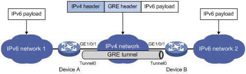
As shown in Figure 79, an IPv6 protocol packet traverses an IPv4 network through a GRE tunnel as follows:
1. After receiving an IPv6 packet from the interface connected to IPv6 network 1, Device A processes the packet as follows:
a. Looks up the routing table to identify the outgoing interface for the IPv6 packet.
b. Submits the IPv6 packet to the outgoing interface—the GRE tunnel interface Tunnel 0.
2. Upon receiving the packet, the tunnel interface encapsulates the packet with GRE and then with IPv4. In the IPv4 header:
? The source address is the tunnel's source address (the IP address of interface GigabitEthernet 1/0/1 of Device A).
? The destination address is the tunnel's destination address (the IP address of interface GigabitEthernet 1/0/1 of Device B).
3. Device A looks up the routing table according to the destination address in the IPv4 header, and forwards the IPv4 packet out of the physical interface (GigabitEthernet 1/0/1) of the GRE tunnel.
4. When the IPv4 arrives at the GRE tunnel destination Device B, Device B checks the destination address. Because the destination is Device B itself and the protocol number in the IP header is 47 (the protocol number for GRE), Device B submits the packet to GRE for de-encapsulation.
5. GRE first removes the IPv4 header, and then checks the GRE key, checksum, and packet sequence number. After GRE finishes the checking, it removes the GRE header, and submits the payload to the IPv6 protocol for forwarding.
|
|
NOTE: GRE encapsulation and de-encapsulation can decrease the forwarding efficiency of tunnel-end devices. |
GRE security mechanisms
GRE supports the following security mechanisms:
· GRE key—Ensures packet validity. The sender adds a GRE key into a packet. The receiver compares the GRE key with its own GRE key. If the two keys are the same, the receiver accepts the packet. If the two keys are different, the receiver drops the packet.
· GRE checksum—Ensures packet integrity. The sender calculates a checksum for the GRE header and payload and sends the packet containing the checksum to the tunnel peer. The receiver calculates a checksum for the received packet and compares it with that carried in the packet. If the checksums are the same, the receiver considers the packet intact and continues to process the packet. If the checksums are different, the receiver discards the packet.
GRE application scenarios
The following shows typical GRE application scenarios:
Connecting networks running different protocols over a single backbone
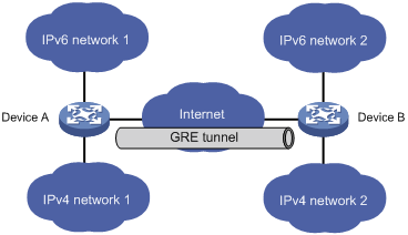
As shown in Figure 80, IPv6 network 1 and IPv6 network 2 are IPv6 networks, and IPv4 network 1 and IPv4 network 2 are IPv4 networks. Through the GRE tunnel between Device A and Device B, IPv6 network 1 can communicate with IPv6 network 2 and IPv4 network 1 can communicate with IPv4 network 2, without affecting each other.
Enlarging network scope
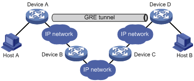
In an IP network, the maximum TTL value of a packet is 255. If two devices have more than 255 hops in between, they cannot communicate with each other. By using a GRE tunnel, you can hide some hops to enlarge the network scope. As shown in Figure 81, only the tunnel-end devices (Device A and Device D) of the GRE tunnel are counted in hop count calculation. Therefore, there are only three hops between Host A and Host B.
Protocols and standards
· RFC 1701, Generic Routing Encapsulation (GRE)
· RFC 1702, Generic Routing Encapsulation over IPv4 networks
· RFC 2784, Generic Routing Encapsulation (GRE)
· RFC 2890, Key and Sequence Number Extensions to GRE
Configuring a GRE/IPv4 tunnel
Perform this task to configure a GRE tunnel on an IPv4 network.
Configuration guidelines
Follow these guidelines when you configure a GRE/IPv4 tunnel:
· You must configure the tunnel source address and destination address at both ends of a tunnel. The tunnel source or destination address at one end must be the tunnel destination or source address at the other end.
· H3C recommends not configuring the same tunnel source and destination addresses for local tunnel interfaces that use the same tunnel mode.
· You can enable or disable GRE checksum at each end of a tunnel. If GRE checksum is enabled at a tunnel end, the tunnel end sends packets carrying the checksum to the peer end. A tunnel end checks the GRE checksum of a received packet if the packet carries a GRE checksum, whether or not the tunnel end is enabled with GRE checksum.
· To ensure correct packet forwarding, identify whether the destination network of packets and the IP address of the local tunnel interface are on the same subnet. If they are not, configure a route reaching the destination network through the tunnel interface. You can configure the route by using one of the following methods:
? Configure a static route, using the local tunnel interface as the outgoing interface of the route.
? Enable a dynamic routing protocol on both the tunnel interface and the interface connecting the private network. This allows the dynamic routing protocol to establish a routing entry with the tunnel interface as the outgoing interface.
· The IP address of the tunnel interface and the tunnel destination address configured on the tunnel interface must be in different subnets.
Configuration procedure
To configure a GRE/IPv4 tunnel:
|
Step |
Command |
Remarks |
|
|
1. Enter system view. |
system-view |
N/A |
|
|
2. Create a GRE tunnel interface, and specify the tunnel mode as GRE/IPv4. |
interface tunnel interface-number mode gre |
By default, the device has no tunnel interface. You must configure the same tunnel mode on both ends of a tunnel. Otherwise, packet delivery might fail. |
|
|
3. Configure an IPv4 or IPv6 address for the tunnel interface. |
For information about how to assign an IPv4 address to an interface, see "Configuring IP addressing." For information about how to assign an IPv6 address to an interface, see "Configuring basic IPv6 settings." |
By default, no IPv4 or IPv6 address is configured for a tunnel interface. When the passenger protocol is IPv4, configure an IPv4 address for the tunnel interface. When the passenger protocol is IPv6, configure an IPv6 address for the tunnel interface. |
|
|
4. Configure a source address or source interface for the tunnel interface. |
source { ip-address | interface-type interface-number } |
By default, no source address or interface is configured for a tunnel interface. If you configure a source address for a tunnel interface, the tunnel interface uses the source address as the source address of the encapsulated packets. If you configure a source interface for a tunnel interface, the tunnel interface uses the primary IP address of the source interface as the source address of the encapsulated packets. |
|
|
5. Configure a destination address for the tunnel interface. |
destination ip-address |
By default, no destination address is configured for a tunnel interface. The destination address is the address of the physical interface that the tunnel remote end uses to receive packets from the GRE tunnel. The tunnel local end uses this address as the destination address of the encapsulated packets. |
|
|
6. (Optional.) Configure a description for the tunnel interface. |
description text |
By default, the description for a tunnel interface is Tunnelnumber Interface. |
|
|
7. (Optional.) Set the MTU of the tunnel interface. |
mtu size |
By default, if the tunnel interface has never been up, the MTU is 64000 bytes. If the tunnel interface is up, its MTU is identical to the outgoing interface's MTU minus the length of the tunnel headers. The outgoing interface is automatically obtained through routing table lookup based on the tunnel destination address. |
|
|
8. (Optional.) Set the expected bandwidth for the tunnel interface. |
bandwidth bandwidth-value |
The default expected bandwidth (in kbps) is the interface maximum rate divided by 1000. The expected bandwidth for the tunnel interface affects the link cost value. |
|
|
9. (Optional.) Set the ToS for tunneled packets. |
tunnel tos tos-value |
The default setting is the same as the ToS of the original packets. |
|
|
10. (Optional.) Set the TTL for tunneled packets. |
tunnel ttl ttl-value |
The default TTL for tunneled packets is 255. |
|
|
11. (Optional.) Enable GRE keepalive, and set the keepalive interval and keepalive number. |
keepalive [ interval [ times ] ] |
By default, GRE keepalive is disabled. |
|
|
12. (Optional.) Enable GRE checksum. |
gre checksum |
By default, GRE checksum is disabled. |
|
|
13. (Optional.) Configure a GRE key for the GRE tunnel interface. |
gre key key-number |
By default, no GRE key is configured for a GRE tunnel interface. The two ends of a GRE tunnel must have the same key or both have no key. |
|
|
14. (Optional.) Set the DF bit for encapsulated packets. |
tunnel dfbit enable |
By default, the DF bit is not set, allowing encapsulated packets to be fragmented. |
|
|
15. (Optional.) Restore the default settings of the tunnel interface. |
default |
N/A |
|
|
16. (Optional.) Shut down the tunnel interface. |
shutdown |
By default, the tunnel interface is not in the Administratively DOWN state. |
|
Configuring a GRE/IPv6 tunnel
Perform this task to configure a GRE tunnel on an IPv6 network.
Configuration guidelines
Follow these guidelines when you configure a GRE/IPv6 tunnel:
· You must configure the tunnel source address and destination address at both ends of a tunnel. The tunnel source or destination address at one end must be the tunnel destination or source address at the other end.
· H3C recommends not configuring the same tunnel source and destination addresses for local tunnel interfaces that use the same tunnel mode.
· You can enable or disable GRE checksum at each end of a tunnel. If GRE checksum is enabled at a tunnel end, the tunnel end sends packets carrying the checksum to the peer end. A tunnel end checks the GRE checksum of a received packet if the packet carries a GRE checksum, whether or not the tunnel end is enabled with GRE checksum.
· To ensure correct packet forwarding, identify whether the destination network of packets and the IP address of the local tunnel interface are on the same subnet. If they are not, configure a route reaching the destination network through the tunnel interface. You can configure the route by using the following methods:
? Configure a static route, using the local tunnel interface as the outgoing interface of the route.
? Enable a dynamic routing protocol on both the tunnel interface and the interface connecting the private network. This allows the dynamic routing protocol to establish a routing entry with the tunnel interface as the outgoing interface.
· The IP address of the tunnel interface and the tunnel destination address configured on the tunnel interface must be in different subnets.
Configuration procedure
To configure a GRE/IPv6 tunnel:
|
Step |
Command |
Remarks |
|
1. Enter system view. |
system-view |
N/A |
|
2. Create a GRE tunnel interface, and specify the tunnel mode as GRE/IPv6. |
interface tunnel interface-number mode gre ipv6 |
By default, the device has no tunnel interface. You must configure the same tunnel mode on both ends of a tunnel. Otherwise, packet delivery might fail. |
|
3. Configure an IPv4 or IPv6 address for the tunnel interface. |
For information about how to assign an IPv4 address to an interface, see "Configuring IP addressing." For information about how to assign an IPv6 address to an interface, see "Configuring basic IPv6 settings." |
By default, no IPv4 or IPv6 address is configured for a tunnel interface. When the passenger protocol is IPv4, configure an IPv4 address for the tunnel interface. When the passenger protocol is IPv6, configure an IPv6 address for the tunnel interface. |
|
4. Configure a source IPv6 address or source interface for the tunnel interface. |
source { ipv6-address | interface-type interface-number } |
By default, no source IPv6 address or interface is configured for a tunnel interface. If you configure a source IPv6 address for a tunnel interface, the tunnel interface uses the source IPv6 address as the source IPv6 address of the encapsulated packets. If you configure a source interface for a tunnel interface, the tunnel interface uses the IPv6 address of the source interface as the source IPv6 address of the encapsulated packets. |
|
5. Configure a destination IPv6 address for the tunnel interface. |
destination ipv6-address |
By default, no destination IPv6 address is configured for a tunnel interface. The destination IPv6 address is the IPv6 address of the physical interface that the tunnel remote end uses to receive packets from the GRE tunnel. The tunnel local end uses this address as the destination IPv6 address of the encapsulated packets. |
|
6. (Optional.) Configure a description for the tunnel interface. |
description text |
By default, the description for a tunnel interface is Tunnelnumber Interface. |
|
7. (Optional.) Set the MTU of the tunnel interface. |
mtu size |
By default, if the tunnel interface has never been up, the MTU is 64000 bytes. If the tunnel interface is up, its MTU is identical to the outgoing interface's MTU minus the length of the tunnel headers. The outgoing interface is automatically obtained through routing table lookup based on the tunnel destination address. |
|
8. (Optional.) Set the expected bandwidth for the tunnel interface. |
bandwidth bandwidth-value |
The default expected bandwidth (in kbps) is the interface maximum rate divided by 1000. The expected bandwidth for the tunnel interface affects the link cost value. |
|
9. (Optional.) Set the ToS for tunneled packets. |
tunnel tos tos-value |
The default setting is the same as the ToS of the original packets. |
|
10. (Optional.) Set the TTL for tunneled packets. |
tunnel ttl ttl-value |
The default TTL for tunneled packets is 255. |
|
11. (Optional.) Enable GRE checksum. |
gre checksum |
By default, GRE checksum is disabled. |
|
12. (Optional.) Configure a GRE key for the tunnel interface. |
gre key key-number |
By default, no GRE key is configured for a GRE tunnel interface. The two ends of a GRE tunnel must have the same key or both have no key. |
|
13. (Optional.) Restore the default settings of the tunnel interface. |
default |
N/A |
|
14. (Optional.) Shut down the tunnel interface. |
shutdown |
By default, the tunnel interface is not in the Administratively DOWN state. |
Displaying and maintaining GRE
Execute display commands in any view and reset commands in user view.
|
Task |
Command |
Remarks |
|
Display information about tunnel interfaces. |
display interface [ tunnel [ number ] ] [ brief [ description | down ] ] |
N/A |
|
Display IPv6 information about tunnel interface. |
display ipv6 interface [ tunnel [ number ] ] [ brief ] |
For more information about this command, see Layer 3—IP Services Command Reference. |
|
Clear tunnel interface statistics. |
reset counters interface [ tunnel [ number ] ] |
N/A |
GRE configuration examples
Configuring an IPv4 over IPv4 GRE tunnel
Network requirements
Group 1 and Group 2 are two private IPv4 networks. The two networks both use private network addresses. Establish a GRE tunnel between the AC and the device to interconnect the two private IPv4 networks Group 1 and Group 2.
Figure 82 Network diagram
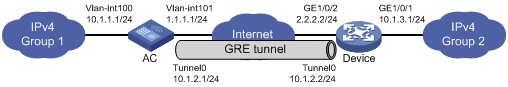
Configuration procedure
Before performing the following configuration, configure an IP address for each interface, and make sure the AC and the device can reach each other.
1. Configure the AC:
# Create tunnel interface Tunnel 0, and specify the tunnel mode as GRE/IPv4.
[AC] interface tunnel 0 mode gre
# Configure an IP address for the tunnel interface.
[AC-Tunnel0] ip address 10.1.2.1 255.255.255.0
# Configure the source address of tunnel interface as the IP address of VLAN-interface 101 on the AC.
[AC-Tunnel0] source 1.1.1.1
# Configure the destination address of the tunnel interface as the IP address of GigabitEthernet 1/0/2 on the device.
[AC-Tunnel0] destination 2.2.2.2
[AC-Tunnel0] quit
# Configure a static route from the AC through the tunnel interface to Group 2.
[AC] ip route-static 10.1.3.0 255.255.255.0 tunnel 0
2. Configure the device:
# Create tunnel interface Tunnel 0, and specify the tunnel mode as GRE/IPv4.
[Device] interface tunnel 0 mode gre
# Configure an IP address for the tunnel interface.
[Device-Tunnel0] ip address 10.1.2.2 255.255.255.0
# Configure the source address of tunnel interface as the IP address of GigabitEthernet 1/0/2 on the device.
[Device-Tunnel0] source 2.2.2.2
# Configure the destination address of the tunnel interface as the IP address of VLAN-interface 101 on the AC.
[Device-Tunnel0] destination 1.1.1.1
[Device-Tunnel0] quit
# Configure a static route from the device through the tunnel interface to Group 1.
[Device] ip route-static 10.1.1.0 255.255.255.0 Tunnel 0
Verifying the configuration
# Display tunnel interface information on the AC.
[AC] display interface tunnel 0
Tunnel0
Current state: UP
Line protocol state: UP
Description: Tunnel0 Interface
Bandwidth: 64kbps
Maximum transmission unit: 64000
Internet address: 10.1.2.1/24 (primary)
Tunnel source 1.1.1.1 (Vlan-interface101), destination 2.2.2.2
Tunnel keepalive disabled
Tunnel TTL 255
Tunnel protocol/transport GRE/IP
GRE key disabled
Checksumming of GRE packets disabled
Last clearing of counters: Never
Last 300 seconds input rate: 0 bytes/sec, 0 bits/sec, 0 packets/sec
Last 300 seconds output rate: 0 bytes/sec, 0 bits/sec, 0 packets/sec
Input: 0 packets, 0 bytes, 0 drops
Output: 0 packets, 0 bytes, 0 drops
# Display tunnel interface information on the device.
[Device] display interface tunnel 0
Tunnel0
Current state: UP
Line protocol state: UP
Description: Tunnel0 Interface
Bandwidth: 64kbps
Maximum transmission unit: 64000
Internet address: 10.1.2.2/24 (primary)
Tunnel source 2.2.2.2, destination 1.1.1.1
Tunnel keepalive disabled
Tunnel TTL 255
Tunnel protocol/transport GRE/IP
GRE key disabled
Checksumming of GRE packets disabled
Last clearing of counters: Never
Last 300 seconds input rate: 0 bytes/sec, 0 bits/sec, 0 packets/sec
Last 300 seconds output rate: 0 bytes/sec, 0 bits/sec, 0 packets/sec
Input: 0 packets, 0 bytes, 0 drops
Output: 0 packets, 0 bytes, 0 drops
# From the device, ping the IP address of VLAN-interface 100 on the AC.
[Device] ping -a 10.1.3.1 10.1.1.1
Ping 10.1.1.1 (10.1.1.1) from 10.1.3.1: 56 data bytes, press CTRL_C to break
56 bytes from 10.1.1.1: icmp_seq=0 ttl=255 time=11.000 ms
56 bytes from 10.1.1.1: icmp_seq=1 ttl=255 time=1.000 ms
56 bytes from 10.1.1.1: icmp_seq=2 ttl=255 time=0.000 ms
56 bytes from 10.1.1.1: icmp_seq=3 ttl=255 time=0.000 ms
56 bytes from 10.1.1.1: icmp_seq=4 ttl=255 time=0.000 ms
--- Ping statistics for 10.1.1.1 ---
5 packet(s) transmitted, 5 packet(s) received, 0.0% packet loss
round-trip min/avg/max/std-dev = 0.000/2.400/11.000/4.317 ms
The output shows that the device can successfully ping the AC.
Configuring an IPv4 over IPv6 GRE tunnel
Network requirements
Two IPv4 subnets Group 1 and Group 2 are connected to an IPv6 network. Create a GRE/IPv6 tunnel between the AC and the device, so the two IPv4 subnets can communicate with each other through the GRE tunnel over the IPv6 network.
Figure 83 Network diagram
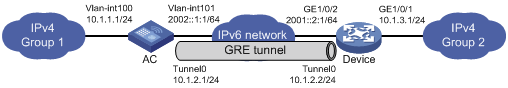
Configuration procedure
Before performing the following configuration, configure an IP address for each interface, and make sure the AC and the device can reach each other.
1. Configure the AC:
# Create tunnel interface Tunnel 0, and specify the tunnel mode as GRE/ IPv6.
[AC] interface tunnel 0 mode gre ipv6
# Configure an IP address for the tunnel interface.
[AC-Tunnel0] ip address 10.1.2.1 255.255.255.0
# Configure the source address of the tunnel interface as the IPv6 address of VLAN-interface 101 on the AC.
[AC-Tunnel0] source 2002::1:1
# Configure the destination address of the tunnel interface as the IPv6 address of GigabitEthernet 1/0/2 on the device.
[AC-Tunnel0] destination 2001::2:1
[AC-Tunnel0] quit
# Configure a static route from the AC through the tunnel interface to Group 2.
[AC] ip route-static 10.1.3.0 255.255.255.0 tunnel 0
2. Configure the device:
# Create tunnel interface Tunnel 0, and specify the tunnel mode as GRE/IPv6.
[Device] interface tunnel 0 mode gre ipv6
# Configure an IP address for the tunnel interface.
[Device-Tunnel0] ip address 10.1.2.2 255.255.255.0
# Configure the source address of tunnel interface as the IPv6 address of GigabitEthernet 1/0/2 on the device.
[Device-Tunnel0] source 2001::2:1
# Configure the destination address of the tunnel interface as the IPv6 address of VLAN-interface 101 on the AC.
[Device-Tunnel0] destination 2002::1:1
[Device-Tunnel0] quit
# Configure a static route from the device through the tunnel interface to Group 1.
[Device] ip route-static 10.1.1.0 255.255.255.0 tunnel 0
Verifying the configuration
# Display tunnel interface information on the AC.
[AC] display interface tunnel 0
Tunnel0
Current state: UP
Line protocol state: UP
Description: Tunnel0 Interface
Bandwidth: 64kbps
Maximum transmission unit: 64000
Internet address: 10.1.2.1/24 (primary)
Tunnel source 2002::1:1, destination 2001::2:1
Tunnel TTL 255
Tunnel protocol/transport GRE/IPv6
GRE key disabled
Checksumming of GRE packets disabled
Last clearing of counters: Never
Last 300 seconds input rate: 0 bytes/sec, 0 bits/sec, 0 packets/sec
Last 300 seconds output rate: 0 bytes/sec, 0 bits/sec, 0 packets/sec
Input: 0 packets, 0 bytes, 0 drops
Output: 0 packets, 0 bytes, 0 drops
# Display tunnel interface information on the device.
[Device] display interface tunnel 0
Tunnel0
Current state: UP
Line protocol state: UP
Description: Tunnel0 Interface
Bandwidth: 64kbps
Maximum transmission unit: 64000
Internet address: 10.1.2.2/24 (primary)
Tunnel source 2001::2:1, destination 2002::1:1
Tunnel TTL 255
Tunnel protocol/transport GRE/IPv6
GRE key disabled
Checksumming of GRE packets disabled
Last clearing of counters: Never
Last 300 seconds input rate: 0 bytes/sec, 0 bits/sec, 0 packets/sec
Last 300 seconds output rate: 0 bytes/sec, 0 bits/sec, 0 packets/sec
Input: 0 packets, 0 bytes, 0 drops
Output: 0 packets, 0 bytes, 0 drops
# From the device, ping the IP address of VLAN-interface 100 on the AC.
[Device] ping -a 10.1.3.1 10.1.1.1
Ping 10.1.1.1 (10.1.1.1) from 10.1.3.1: 56 data bytes, press CTRL_C to break
56 bytes from 10.1.1.1: icmp_seq=0 ttl=255 time=2.000 ms
56 bytes from 10.1.1.1: icmp_seq=1 ttl=255 time=1.000 ms
56 bytes from 10.1.1.1: icmp_seq=2 ttl=255 time=1.000 ms
56 bytes from 10.1.1.1: icmp_seq=3 ttl=255 time=0.000 ms
56 bytes from 10.1.1.1: icmp_seq=4 ttl=255 time=1.000 ms
--- Ping statistics for 10.1.1.1 ---
5 packet(s) transmitted, 5 packet(s) received, 0.0% packet loss
round-trip min/avg/max/std-dev = 0.000/1.000/2.000/0.632 ms
The output shows that the device can successfully ping the AC.
Troubleshooting GRE
The key to configuring GRE is to keep the configuration consistent. Most faults can be located by using the debugging gre or debugging tunnel command. This section analyzes one type of fault for illustration, with the scenario shown in Figure 84.
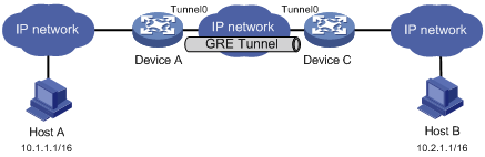
Symptom
The interfaces at both ends of the tunnel are configured correctly and can ping each other, but Host A and Host B cannot ping each other.
Analysis
It might be because that Device A or Device C has no route to reach the peer network.
Solution
1. Execute the display ip routing-table command on Device A and Device C to view whether Device A has a route over tunnel 0 to 10.2.0.0/16 and whether Device C has a route over tunnel 0 to 10.1.0.0/16.
2. If such a route does not exist, execute the ip route-static command in system view to add the route. Take Device A as an example:
[DeviceA] ip route-static 10.2.0.0 255.255.0.0 tunnel 0
Numerics
1:1
NAT configuration (static outbound 1:1), 124
A
ACL
NAT server (ACL-based), 116
NAT translation control, 103
address
DHCP address assignment, 22
DHCP address pool, 22
DHCP address pool application on interface, 34
DHCP address pool selection, 23
DHCP address pool usage alarm, 39
DHCP allocation, 16
DHCP binding auto backup, 38
DHCP BOOTP client IP address acquisition, 76
DHCP client duplicated address detection, 65
DHCP client subnet advertisement, 40
DHCP dynamic address assignment policy, 35
DHCP gateway+server MAC address bind, 39
DHCP IP address allocation sequence, 24
DHCP IP address conflict detection, 36
DHCP IP address lease extension, 17
DHCP relay address pool, 58
DHCP server address pool, 25
DHCP server address pool creation, 25
DHCP server address pool IP address range, 25
DHCPv6 address allocation, 170
DHCPv6 address pool, 169
DHCPv6 address pool selection, 170
DHCPv6 address/prefix assignment, 165
DHCPv6 address/prefix lease renewal, 166
DHCPv6 binding auto backup, 178
DHCPv6 client IPv6 address acquisition, 192
DHCPv6 client IPv6 address+prefix acquisition, 193
DHCPv6 client subnet advertisement, 179
DHCPv6 IA, 169
DHCPv6 IAID, 169
DHCPv6 IPv6 address assignment, 168
DHCPv6 IPv6 address/prefix allocation sequence, 170
DHCPv6 multicast, 169
DHCPv6 overview, 165
DHCPv6 server dynamic IPv6 address assignment, 183
DHCPv6 server IPv6 address and prefix policy assignment, 176
DHCPv6 server IPv6 address assignment, 172
IP address classes, 13
IP addressing configuration, 13
IP addressing interface address, 14
IPPO ICMP packet source address, 136
IPv6 addresses, 139
IPv6 ICMPv6 packet source address, 159
NAT configuration, 102, 109, 124
NAT configuration (dynamic inbound), 113
NAT configuration (dynamic outbound), 112, 125
NAT configuration (dynamic), 112
NAT configuration (static inbound 1:1), 111
NAT configuration (static inbound net-to-net), 111
NAT configuration (static outbound 1:1), 110, 124
NAT configuration (static outbound net-to-net), 110
NAT configuration (static), 109
NAT hairpin, 120
NAT rule priority modification, 118
NAT rule priority modification (ACL-based NAT server), 119
NAT rule priority modification (inbound dynamic), 118
NAT rule priority modification (outbound dynamic), 118
NAT rule priority modification (static inbound 1:1), 119
NAT rule priority modification (static outbound 1:1), 119
NAT translation control, 103
special IP addresses, 14
stateless DHCPv6, 167
Address Resolution Protocol. Use ARP
aging
dynamic ARP entry aging timer, 4
alarm
DHCP address pool usage alarm, 39
IP addressing DHCP address pool usage alarm, 39
NAT444 alarm logging, 122
ALG
NAT support, 109
NAT+ALG configuration, 120
allocating
DHCP address allocation, 22
DHCP addresses allocation, 16
DHCP IP address allocation sequence, 24
DHCPv6 address/prefix allocation sequence, 170
DHCPv6 dynamic address allocation, 170
DHCPv6 dynamic prefix allocation, 170
DHCPv6 static address allocation, 170
DHCPv6 static prefix allocation, 170
Anycast
IPv6 address type, 139
IPv6 anycast address configuration, 149
application scenario
GRE, 206
applying
DDNS client policy to interface, 100
DHCP address pool on interface, 34
DHCPv6 snooping trusted/untrusted port, 196
command and hardware compatibility, 3
common proxy ARP configuration, 10
common proxy ARP enable, 9
configuration, 1
display, 6
dynamic entry aging timer configuration, 4
dynamic entry check enable, 5
dynamic entry max (device), 3
dynamic entry max (interface), 4
dynamic table entry, 2
fast-reply configuration, 11, 11, 11, 11
gratuitous ARP configuration, 7, 7
gratuitous ARP IP conflict notification, 8
gratuitous ARP packet learning, 7
gratuitous ARP periodic packet send, 7
local proxy ARP enable, 9
logging enable, 5
maintain, 6
message format, 1
operation, 1
proxy ARP configuration, 9
static entry configuration, 3
static table entry, 2
table, 2
assembling
IPv6 local fragment reassembly, 159
assigning
DHCP address, 22
DHCPv6 address/prefix, 165
DHCPv6 assignment (4 messages), 165
DHCPv6 IPv6 address, 168
DHCPv6 IPv6 prefix, 168
DHCPv6 rapid assignment (2 messages), 165
DHCPv6 server dynamic IPv6 address assignment, 183
DHCPv6 server dynamic IPv6 prefix assignment, 181
DHCPv6 server IPv6 address and prefix policy assignment, 176
DHCPv6 server IPv6 address assignment, 172
DHCPv6 server IPv6 prefix assignment, 171
DHCPv6 server network parameters (address pool), 174
DHCPv6 server network parameters (option group), 175
DHCPv6 server network parameters assignment, 174
IP addressing interface address, 14
IPv6 interface addresses, 146
auto
DHCP automatic address allocation, 16
DHCP binding auto backup, 38
DHCP client auto-configuration file, 30
DHCP snooping entry auto backup, 70
DHCPv6 binding auto backup, 178
DHCPv6 snooping entry auto backup, 199
IPv6 interface link-local address automatic generation, 149
IPv6 link-local address automatic generation, 148
IPv6 ND stateless address autoconfiguration, 143
IPv6 stateless address autoconfiguration, 147
B
backing up
DHCP binding auto backup, 38
DHCP snooping entries, 70
DHCPv6 binding auto backup, 178
DHCPv6 snooping entry auto backup, 199
bidirectional
NAT, 103
BIMS server information (DHCP client), 30
binding
DHCP gateway+server MAC address bind, 39
blocking
DHCPv6 snooping packet blocking port, 202
client configuration, 76
client display, 77
client dynamic IP address acquisition, 76
DHCP application, 76
DHCP client IP address acquisition, 76
DHCP server BOOTP request ignore, 37
DHCP server BOOTP response format, 37
protocols and standards, 76
Bootstrap Protocol. Use BOOTP
BRAS
NAT444 gateway+BRAS device, 106
broadcast
DHCP server broadcast response, 37
buffer
IPPO TCP buffer size, 133
C
checksum security feature (GRE), 206
class
IP address class, 13
client
DHCP BOOTP configuration, 76
DHCP client auto-configuration file, 30
DHCP client BIMS server information, 30
DHCP client configuration, 64
DHCP client display, 65
DHCP client DNS server, 29
DHCP client domain name suffix, 29
DHCP client duplicated address detection, 65
DHCP client enable (interface), 64
DHCP client gateway, 28
DHCP client ID configuration (interface), 64
DHCP client NetBIOS node type, 29
DHCP client packet DSCP value, 65
DHCP client WINS server, 29
DHCP server specification, 31
DHCP snooping Option 82 support, 67
DHCP voice client Option 184 parameters, 31
DHCPv6 address pool, 169
DHCPv6 client DUID, 194
DHCPv6 client packet DSCP value, 194
DHCPv6 configuration, 192, 192
DHCPv6 IA, 169
DHCPv6 IAID, 169
DHCPv6 IPv6 address acquisition, 192
DHCPv6 IPv6 address+prefix acquisition, 193
DHCPv6 IPv6 prefix acquisition, 193
DHCPv6 IPv6 prefix assignment, 168
DHCPv6 relay agent configuration, 186, 190
DHCPv6 stateless, 193
command
DHCP command and hardware compatibility, 68
DHCPv6 command and hardware compatibility, 197
NAT command and hardware compatibility, 103
command and hardware compatibility
ARP, 3
IP performance, 130
IPv6 basic settings, 145
compatibility
DDNS feature and hardware compatibility, 98
DHCP command and hardware compatibility, 68
DHCPv6 command and hardware compatibility, 197
load sharing and hardware compatibility, 129
NAT command and hardware compatibility, 103
configuring
ARP, 1
ARP fast-reply, 11, 11, 11
common proxy ARP, 10
DDNS, 97
DDNS client, 98
DDNS client policy, 98
DHCP address pool usage alarm, 39
DHCP binding auto backup, 38
DHCP BOOTP client, 76
DHCP BOOTP client IP address acquisition, 76
DHCP client, 64
DHCP client auto-configuration file, 30
DHCP client ID (interface), 64
DHCP client subnet advertisement, 40
DHCP dynamic address assignment policy, 35
DHCP IP address conflict detection, 36
DHCP packet blocking port, 73
DHCP relay address pool, 58
DHCP relay agent, 52, 53, 62
DHCP relay agent IP address release, 57
DHCP relay agent Option 82, 57
DHCP relay agent security features, 55
DHCP server, 22, 24
DHCP server address pool, 25
DHCP server BOOTP request ignore, 37
DHCP server BOOTP response format, 37
DHCP server broadcast response, 37
DHCP server compatibility, 36
DHCP server configuration, 42
DHCP server dynamic IP address assignment, 42
DHCP server option customization, 49
DHCP server subnet, 48
DHCP server user class, 45
DHCP server user class whitelist, 46
DHCP smart relay, 60
DHCP snooping, 66, 68, 74
DHCP snooping basics, 68, 74
DHCP snooping entry auto backup, 70
DHCP snooping Option 82, 69
DHCP snooping packet rate limit, 72
DHCP user class whitelist, 33
DHCP voice client Option 184 parameters, 31
DHCPv6 binding auto backup, 178
DHCPv6 client, 192, 192
DHCPv6 client DUID, 194
DHCPv6 client IPv6 address acquisition, 192
DHCPv6 client IPv6 address+prefix acquisition, 193
DHCPv6 client IPv6 prefix acquisition, 193
DHCPv6 client stateless, 193
DHCPv6 client subnet advertisement, 179
DHCPv6 relay address pool, 189
DHCPv6 relay agent, 186, 187, 190
DHCPv6 server, 168, 171, 181
DHCPv6 server dynamic IPv6 address assignment, 183
DHCPv6 server dynamic IPv6 prefix assignment, 181
DHCPv6 server IPv6 address and prefix policy assignment, 176
DHCPv6 server IPv6 address assignment, 172
DHCPv6 server IPv6 prefix assignment, 171
DHCPv6 server network parameters (address pool), 174
DHCPv6 server network parameters (option group), 175
DHCPv6 server network parameters assignment, 174
DHCPv6 server on interface, 177
DHCPv6 snooping, 196, 198, 203
DHCPv6 snooping basics, 198
DHCPv6 snooping entry auto backup, 199
DHCPv6 snooping Option 18, 199
DHCPv6 snooping Option 37, 199
DHCPv6 snooping packet blocking port, 202
DHCPv6 snooping packet rate limit, 201
DNS, 78, 81
DNS proxy, 83
DNS spoofing, 84
DNS trusted interface, 85
dynamic ARP entry aging timer, 4
gratuitous ARP, 7
GRE, 205, 213
GRE/IPv4 tunnel, 207
GRE/IPv6 tunnel, 210
IP addressing, 13
IP forwarding load sharing, 129
IP forwarding load sharing (per-packet or per-flow), 129
IPPO directed broadcast receive/forward, 130
IPPO ICMP error message rate limit, 135
IPPO interface MTU, 131
IPPO interface TCP MSS, 131
IPPO TCP buffer size, 133
IPPO TCP path MTU discovery, 132
IPPO TCP timers, 133
IPv4 DNS, 86
IPv4 DNS client, 81
IPv4 DNS client dynamic domain name resolution, 82, 87
IPv4 DNS client static domain name resolution, 81, 86
IPv4 DNS proxy, 89
IPv4/IPv4 GRE tunnel, 213
IPv4/IPv6 GRE tunnel, 215
IPv6 address (global unicast)(manual), 146
IPv6 address (global unicast)(prefix application), 148
IPv6 anycast address, 149
IPv6 basic settings, 138, 145, 161
IPv6 DNS, 91
IPv6 DNS client, 82
IPv6 DNS client dynamic domain name resolution, 83, 91
IPv6 DNS client static domain name resolution, 82, 91
IPv6 DNS proxy, 94
IPv6 dynamic path MTU aging timer, 157
IPv6 EUI-64 address, 146
IPv6 global unicast address, 146
IPv6 ICMPv6 error message rate limit, 157
IPv6 interface link-local address automatic generation, 149
IPv6 interface MTU, 156
IPv6 link-local address, 148
IPv6 max number NS message sent attempts, 154
IPv6 ND, 150
IPv6 ND customer-side port, 156
IPv6 ND static neighbor entry, 150
IPv6 packet with extension headers discarding, 160
IPv6 path MTU discovery, 156
IPv6 RA message parameter, 151, 153
IPv6 stateless address autoconfiguration, 147
IPv6 static path MTU, 156
NAT, 102, 109, 124
NAT (dynamic inbound), 113
NAT (dynamic outbound), 112, 125
NAT (dynamic), 112
NAT (static inbound 1:1), 111
NAT (static inbound net-to-net), 111
NAT (static outbound 1:1), 110, 124
NAT (static outbound net-to-net), 110
NAT (static), 109
NAT hairpin, 120
NAT logging, 121
NAT server, 114
NAT server (ACL-based), 116
NAT server (common), 114
NAT server (load sharing), 115
NAT session logging, 121
NAT+ALG, 120
NAT+DNS mapping, 119
NAT444, 116
NAT444 (dynamic), 117
NAT444 (static), 116
NAT444 alarm logging, 122
NAT444 port block usage threshold (dynamic), 122
NAT444 user logging, 121
proxy ARP, 9
static ARP entry, 3
conflict
gratuitous ARP IP conflict notification, 8
controlling
IPv6 ICMPv6 message send, 157
cookie (TCP SYN), 133
creating
DHCP server address pool, 25
customer
IPv6 ND customer-side port, 156
customizing
DHCP options, 19, 32
DHCP server option customization, 49
D
application, 97
client, 97
client configuration, 98
client policy application, 100
client policy configuration, 98
configuration, 97
DDNS feature and hardware compatibility, 98
display, 101
outgoing packet DSCP value, 101
server, 97
destination unreachable message (ICMPv6), 158
detecting
DHCP client duplicated address detection, 65
DHCP client offline detection, 41
DHCP IP address conflict detection, 36
DHCP relay agent client offline detection, 60
IPv6 ND duplicate address detection, 142
IPv6 ND neighbor reachability detection, 142
IPv6 ND redirection, 143
IPv6 ND router/prefix discovery, 143
device
common proxy ARP configuration, 10
DDNS client policy application, 100
DDNS outgoing packet DSCP value, 101
DHCP client packet DSCP value, 65
DHCP overview, 16
DHCP relay agent packet DSCP value, 58
DHCP server configuration, 22, 24
DHCP server packet DSCP value, 38
DHCP snooping entry max, 72
DHCPv6 client DUID, 194
DHCPv6 client packet DSCP value, 194
DHCPv6 DUID, 169
DHCPv6 IA, 169
DHCPv6 IAID, 169
DHCPv6 packet DSCP value, 178
DHCPv6 PD, 169
DHCPv6 server configuration, 168, 171
DNS outgoing packet DSCP value, 85
DNS packet source interface, 84
DNS proxy, 79
DNS proxy configuration, 83
DNS spoofing, 80
DNS spoofing configuration, 84
DNS trusted interface, 85
dynamic ARP entry max (device), 3
dynamic ARP entry max (interface), 4
IP forwarding load sharing (per-packet or per-flow), 129
IPPO ICMP error message send, 134
IPPO interface MTU configuration, 131
IPPO interface TCP MSS configuration, 131
IPPO TCP buffer size, 133
IPPO TCP path MTU discovery, 132
IPPO TCP SYN cookie, 133
IPPO TCP timer, 133
IPv4 DNS client configuration, 81
IPv4 DNS proxy configuration, 89
IPv6 DNS client configuration, 82
IPv6 DNS proxy configuration, 94
NAT rule priority modification, 118
NAT rule priority modification (ACL-based NAT server), 119
NAT rule priority modification (inbound dynamic), 118
NAT rule priority modification (outbound dynamic), 118
NAT rule priority modification (static inbound 1:1), 119
NAT rule priority modification (static outbound 1:1), 119
NAT server (ACL-based), 116
NAT server (common), 114
NAT server (load sharing), 115
NAT server configuration, 114
NAT444 gateway+BRAS device, 106
server Option 60 encapsulation in DHCP reply, 38
stateless DHCPv6, 167
address allocation, 16
address assignment, 22
address pool, 22
address pool application on interface, 34
address pool selection, 23
address pool usage alarm, 39
binding auto backup, 38
BOOTP application, 76
BOOTP client configuration, 76
BOOTP client display, 77
BOOTP client dynamic IP address acquisition, 76
BOOTP client IP address acquisition, 76
BOOTP protocols and standards, 76
client auto-configuration file, 30
client BIMS server information, 30
client configuration, 64
client display, 65
client DNS server, 29
client domain name suffix, 29
client duplicated address detection, 65
client enable (interface), 64
client gateway specification, 28
client ID configuration (interface), 64
client NetBIOS node type, 29
client packet DSCP value, 65
client server specification, 31
client subnet advertisement, 40
client WINS server specification, 29
DHCP command and hardware compatibility, 68
DHCPv6. See DHCPv6
dynamic address assignment policy, 35
enable, 34
enabling Option 82 handling, 36
gateway+server MAC address bind, 39
IP address allocation, 17
IP address allocation sequence, 24
IP address conflict detection, 36
IP address lease extension, 17
message format, 18
Option #, 19, See also Option #
Option 121, 19
Option 150, 19
Option 184 (reserved), 19, 21
Option 3;Option 003, 19
Option 33;Option 033, 19
Option 43 (vendor-specific);Option 043 (vendor-specific), 19, 19
Option 51;Option 051, 19
Option 53;Option 053, 19
Option 55;Option 055, 19
Option 6;Option 006, 19
Option 60;Option 060, 19
Option 66;Option 066, 19
Option 67;Option 067, 19
Option 82 (relay agent);Option 082 (relay agent), 19, 20
option customization, 32
options (custom), 19
options (DHCP server's), 19
overview, 16
protocols and standards, 21
relay agent client gateway address, 59
relay agent client offline detection, 60
relay agent configuration, 52, 53, 62
relay agent display, 61
relay agent enable (on interface), 54
relay agent entry periodic refresh, 55
relay agent IP address release, 57
relay agent maintain, 61
relay agent operation, 52
relay agent Option 82 configuration, 57
relay agent Option 82 support, 53
relay agent packet DSCP value, 58
relay agent relay entry recording, 55
relay agent security features, 55
relay agent server proxy, 58
relay agent starvation attack protection, 56
server address pool configuration, 25
server address pool creation, 25
server address pool IP address range, 25
server BOOTP request ignore, 37
server BOOTP response format, 37
server broadcast response, 37
server client offline detection, 41
server compatibility configuration, 36
server configuration, 22, 24, 42
server display, 41
server dynamic IP address assignment, 42
server enable on interface, 34
server logging, 41
server maintain, 41
server Option 60 encapsulation in DHCP reply, 38
server option customization configuration, 49
server packet DSCP value, 38
server specification (relay agent), 54
server subnet configuration, 48
server user class configuration, 45
server user class whitelist configuration, 46
smart relay, 60
snooping. See DHCP snooping
troubleshoot IP address conflict, 51
troubleshoot relay agent configuration, 63
troubleshoot relay agent configuration parameters, 63
troubleshoot server configuration, 51
user class whitelist configuration, 33
voice client Option 184 parameters, 31
DHCP server's
DHCP options, 19
basic configuration, 68
basics configuration, 74
configuration, 66, 68, 74
DHCP-REQUEST message attack protection, 71
display, 73
entry auto backup, 70
entry max, 72
logging, 73
maintain, 73
Option 82 configuration, 69
Option 82 support, 67
packet blocking port, 73
packet rate limit, 72
starvation attack protection, 71
trusted port, 66
untrusted port, 66
DHCP-REQUEST message attack protection, 71
address allocation, 170
address pool, 169
address pool selection, 170
address/prefix assignment, 165
address/prefix lease renewal, 166
assignment (4 messages), 165
client configuration, 192, 192
client configuration restrictions, 192
client display, 194
client DUID, 194
client gateway address, 189
client IPv6 address acquisition, 192
client IPv6 address+prefix acquisition, 193
client IPv6 prefix acquisition, 193
client maintain, 194
client packet DSCP value, 194
client stateless DHCPv6, 193
client subnet advertisement, 179
concepts, 169
DHCPv6 binding auto backup, 178
DHCPv6 command and hardware compatibility, 197
DUID, 169
IA, 169
IAID, 169
IPv6 address assignment, 168
IPv6 address/prefix allocation sequence, 170
IPv6 prefix assignment, 168
multicast address, 169
overview, 165
PD, 169
prefix allocation, 170
protocols and standards, 167
rapid assignment (2 messages), 165
relay address pool configuration, 189
relay agent configuration, 186, 187, 190
relay agent display, 190
relay agent enable on interface, 187
relay agent Interface-ID option padding mode, 188
relay agent maintain, 190
relay agent packet DSCP value, 188
relay agent server, 187
server configuration, 168, 171, 181
server configuration on interface, 177
server display, 180
server dynamic IPv6 address assignment, 183
server dynamic IPv6 prefix assignment, 181
server IPv6 address and prefix policy assignment, 176
server IPv6 address assignment, 172
server IPv6 prefix assignment, 171
server logging, 180
server maintain, 180
server network parameters (address pool), 174
server network parameters (option group), 175
server network parameters assignment, 174
snooping. See DHCPv6 snooping
stateless DHCPv6, 167
basic configuration, 198
configuration, 196, 198, 203
DHCPv6-REQUEST check, 201
display, 202
logging enable, 202
maintain, 202
Option 18 configuration;Option 018 configuration, 199
Option 18;Option 018, 197
Option 37 configuration;Option 037 configuration, 199
Option 37;Option 037, 197
packet blocking port, 202
packet rate limit configuration, 201
snooping entry auto backup, 199
snooping entry max, 200
DHCPv6-REQUEST check, 201
disabling
Option 60 encapsulation in DHCP reply, 38
discarding
IPv6 packets with extension headers, 160
displaying
ARP, 6
DDNS, 101
DHCP BOOTP client, 77
DHCP client, 65
DHCP relay agent, 61
DHCP server, 41
DHCP snooping, 73
DHCPv6 client, 194
DHCPv6 relay agent, 190
DHCPv6 server, 180
DHCPv6 snooping, 202
DNS, 85
GRE, 212
IP addressing, 15
IPPO, 136
IPv6 basics, 160
NAT, 123
proxy ARP, 9
configuration, 78, 81
DDNS configuration, 97
DDNS outgoing packet DSCP value, 101
DHCP client domain name suffix, 29
DHCP client server, 29
display, 85
dynamic domain name resolution, 78
IPv4 client configuration, 81
IPv4 client dynamic domain name resolution, 82, 87
IPv4 client static domain name resolution, 81, 86
IPv4 configuration, 86
IPv4 proxy configuration, 89
IPv6 client configuration, 82
IPv6 client dynamic domain name resolution, 83, 91
IPv6 client static domain name resolution, 82, 91
IPv6 configuration, 91
IPv6 proxy configuration, 94
maintain, 85
NAT DNS mapping support, 108
NAT+DNS mapping configuration, 119
outgoing packet DSCP value, 85
packet source interface, 84
proxy, 79
proxy configuration, 83
spoofing, 80
spoofing configuration, 84
static domain name resolution, 78
suffixes, 79
troubleshoot IPv4 DNS address resolution failure, 95
troubleshoot IPv4 DNS configuration, 95
troubleshoot IPv6 DNS address resolution failure, 96
troubleshoot IPv6 DNS configuration, 96
trusted interface configuration, 85
domain
DHCP client domain name suffix, 29
Domain Name System. Use DNS
DSCP
DDNS outgoing packet DSCP value, 101
DHCP client packet DSCP value, 65
DHCP relay agent packet DSCP value, 58
DHCP server packet DSCP value, 38
DHCPv6 client packet DSCP value, 194
DHCPv6 packet value, 178
DHCPv6 relay agent packet DSCP value, 188
DNS outgoing packet DSCP value, 85
dual stack technology, 144
DUID
DHCPv6 client DUID, 194
DUID (DHCPv6), 169
duplicate
DHCP client duplicated address detection, 65
dynamic
ARP entry aging timer, 4
ARP entry check enable, 5
ARP entry max (device), 3
ARP entry max (interface), 4
ARP table entry, 2
DDNS client configuration, 98
DDNS configuration, 97
DHCP address allocation, 16, 22
DHCP relay agent entry periodic refresh, 55
DHCP server dynamic IP address assignment, 42
DHCP server user class whitelist, 46
DHCPv6 dynamic address allocation, 170
DHCPv6 dynamic prefix allocation, 170
DHCPv6 server dynamic IPv6 address assignment, 183
DHCPv6 server dynamic IPv6 prefix assignment, 181
DNS domain name resolution, 78
Dynamic Host Configuration Protocol. Use DHCP
IPv4 DNS client dynamic domain name resolution, 82, 87
IPv6 DNS client dynamic domain name resolution, 83, 91
IPv6 dynamic path MTU aging timer, 157
NAT, 103
NAT configuration, 112
NAT configuration (dynamic inbound), 113
NAT configuration (dynamic outbound), 112
NAT444 configuration (dynamic), 117
NAT444 mapping, 106
NAT444 mapping global sharing enable (dynamic), 118
NAT444 port block usage threshold configuration (dynamic), 122
Dynamic Domain Name System. Use DDNS
E
Easy IP (NAT), 102
enabling
ARP logging, 5
DHCP, 34
DHCP client (interface), 64
DHCP client duplicated address detection, 65
DHCP Option 82 handling, 36
DHCP relay agent (on interface), 54
DHCP relay agent relay entry recording, 55
DHCP relay agent server proxy, 58
DHCP relay agent starvation attack protection, 56
DHCP snooping logging, 73
DHCP snooping starvation attack protection, 71
DHCPv6 relay agent on interface, 187
dynamic ARP entry check, 5
gratuitous ARP, 7
gratuitous ARP IP conflict notification, 8
IPPO directed broadcast forward, 130
IPPO ICMP error message send, 134
IPPO IPv4 local fragment reassembly, 136
IPv6 ICMPv6 destination unreachable message, 158
IPv6 ICMPv6 redirect message, 159
IPv6 ICMPv6 time exceeded message, 158
IPv6 local fragment reassembly, 159
IPv6 multicast echo request reply, 157
local proxy ARP, 9
NAT444 mapping global sharing (dynamic), 118
Enabling
NAT sending ICMP error message, 123
enabling
common proxy ARP, 9
DHCP relay agent client offline detection, 60
DHCP relay agent entry periodic refresh, 55
DHCP server client offline detection, 41
DHCP server logging, 41
DHCP server on interface, 34
DHCP-REQUEST message attack protection, 71
DHCPv6 server logging, 180
DHCPv6 snooping logging, 202
DHCPv6-REQUEST check, 201
IPPO TCP SYN cookie, 133
IPv6 ND proxy, 154
IPv6 RA message send, 152
encapsulating
GRE configuration, 205, 213
GRE encapsulation format, 205
IPv4/IPv4 GRE tunnel, 213
IPv4/IPv6 GRE tunnel, 215
error
IPPO ICMP error message sending, 134
Ethernet
ARP configuration, 1
ARP fast-reply configuration, 11, 11
common proxy ARP configuration, 10
DHCP BOOTP client configuration, 76
DHCP client configuration, 64
DHCP server configuration, 22, 24, 42
DHCP server dynamic IP address assignment, 42
DHCP server option customization, 49
DHCP server subnet, 48
DHCP server user class, 45
DHCP server user class whitelist, 46
DHCP snooping basic configuration, 74
DHCPv6 client configuration, 192
DHCPv6 snooping configuration, 196, 198, 203
gratuitous ARP configuration, 7
proxy ARP configuration, 9
EUI-64 address
IP services address-based interface identifiers, 141
IP services configuration, 146
extending
DHCP IP address lease extension, 17
F
fast
ARP fast-reply configuration, 11, 11
feature
DDNS feature and hardware compatibility, 98
FIB
IP forwarding load sharing (per-packet or per-flow), 129
FIN wait timer, 133
format
ARP message format, 1
DHCP message, 18
DHCP server BOOTP response format, 37
GRE encapsulation format, 205
IPv6 addresses, 139
forwarding
IPPO directed broadcast forward, 130
fragment
IPv6 local fragment reassembly, 159
G
gateway
DHCP client gateway specification, 28
DHCP gateway+server MAC address bind, 39
DHCP relay agent client gateway address, 59
DHCPv6 client gateway address, 189
NAT configuration, 102, 109, 124
NAT configuration (dynamic inbound), 113
NAT configuration (dynamic outbound), 112, 125
NAT configuration (dynamic), 112
NAT configuration (static inbound 1:1), 111
NAT configuration (static inbound net-to-net), 111
NAT configuration (static outbound 1:1), 110, 124
NAT configuration (static outbound net-to-net), 110
NAT configuration (static), 109
NAT rule priority modification, 118
NAT rule priority modification (ACL-based NAT server), 119
NAT rule priority modification (inbound dynamic), 118
NAT rule priority modification (outbound dynamic), 118
NAT rule priority modification (static inbound 1:1), 119
NAT rule priority modification (static outbound 1:1), 119
NAT444 gateway+BRAS device, 106
Generic Routing Encapsulation. Use GRE
gratuitous ARP
configuration, 7, 7
IP conflict notification, 8
packet learning, 7
periodic packet send, 7
application scenario, 206
configuration, 205, 213
display, 212
encapsulation format, 205
GRE/IPv4 tunnel configuration, 207
GRE/IPv6 tunnel configuration, 210
IPv4/IPv4 GRE tunnel configuration, 213
IPv4/IPv6 GRE tunnel configuration, 215
maintain, 212
protocols and standards, 207
security features, 206
troubleshoot, 217
troubleshoot hosts cannot ping each other, 217
tunnel operation, 205
H
hairpin
NAT hairpin C/S, 103
NAT hairpin configuration, 120
NAT hairpin P2P, 103
hardware
DDNS feature and hardware compatibility, 98
DHCP command and hardware compatibility, 68
DHCPv6 command and hardware compatibility, 197
load sharing and hardware compatibility, 129
NAT command and hardware compatibility, 103
I
IA (DHCPv6), 169
IAID (DHCPv6), 169
ICMP
IPPO ICMP error message rate limit, 135
IPPO ICMP error message send, 134
IPPO ICMP packet source address specification, 136
NAT sending ICMP error message, 123
ICMPv6
IP services destination unreachable message, 158
IP services error message rate limit, 157
IP services packet source address, 159
IP services redirect message, 159
IP services time exceeded message, 158
IPv6 message send control, 157
IPv6 ND duplicate address detection, 142
IPv6 ND neighbor reachability detection, 142
IPv6 ND protocol, 141
IPv6 ND protocol address resolution, 142
IPv6 ND redirection, 143
IPv6 ND router/prefix discovery, 143
IPv6 ND stateless address autoconfiguration, 143
ID
DHCPv6 relay agent Interface-ID option padding mode, 188
IP address class Host ID, 13
IP address class Net ID, 13
identity
association. See IA
association ID. See IAID
ignoring
DHCP server BOOTP request, 37
IP addressing
address classes, 13
ARP configuration, 1
ARP dynamic table entry, 2
ARP fast-reply configuration, 11, 11
ARP message format, 1
ARP operation, 1
ARP static table entry, 2
ARP table, 2
common proxy ARP configuration, 10
configuration, 13
DDNS client configuration, 98
DDNS client policy, 98
DDNS client policy application, 100
DDNS configuration, 97
DHCP address allocation, 16, 17
DHCP address allocation sequence, 24
DHCP address assignment, 22
DHCP address conflict detection, 36
DHCP address pool, 22
DHCP address pool usage alarm, 39
DHCP binding auto backup, 38
DHCP BOOTP client configuration, 76
DHCP BOOTP client dynamic IP address acquisition, 76
DHCP client configuration, 64
DHCP client subnet advertisement, 40
DHCP dynamic address assignment policy, 35
DHCP gateway+server MAC address bind, 39
DHCP lease extension, 17
DHCP message format, 18
DHCP relay agent IP address release, 57
DHCP server address pool IP address range, 25
DHCP server configuration, 42
DHCP server dynamic IP address assignment, 42
DHCP server option customization, 49
DHCP server subnet, 48
DHCP server user class, 45
DHCP server user class whitelist, 46
DHCP snooping basic configuration, 68
DHCP snooping configuration, 66, 68, 74
DHCP user class whitelist, 33
DHCPv6 client configuration, 192
DHCPv6 client IPv6 address acquisition, 192
DHCPv6 client IPv6 address+prefix acquisition, 193
DHCPv6 client IPv6 prefix acquisition, 193
DHCPv6 client stateless, 193
DHCPv6 configuration, 168
DHCPv6 overview, 165
DHCPv6 server configuration, 171, 181
DHCPv6 server configuration on interface, 177
DHCPv6 server dynamic IPv6 address assignment, 183
DHCPv6 server dynamic IPv6 prefix assignment, 181
DHCPv6 server IPv6 address and prefix policy assignment, 176
DHCPv6 server IPv6 address assignment, 172
DHCPv6 server IPv6 prefix assignment, 171
DHCPv6 server network parameters (address pool), 174
DHCPv6 server network parameters (option group), 175
DHCPv6 server network parameters assignment, 174
DHCPv6 snooping configuration, 196, 198, 203
DHCPv6 snooping logging, 202
discarding IPv6 packets with extension headers, 160
display, 15
DNS configuration, 78, 81
DNS dynamic domain name resolution, 78
DNS packet source interface, 84
DNS spoofing, 80
DNS spoofing configuration, 84
DNS static domain name resolution, 78
DNS trusted interface, 85
dynamic ARP entry aging timer, 4
dynamic ARP entry check enable, 5
dynamic ARP entry max (device), 3
dynamic ARP entry max (interface), 4
gratuitous ARP configuration, 7, 7
gratuitous ARP IP conflict notification, 8
gratuitous ARP packet learning, 7
gratuitous ARP periodic packet send, 7
interface IP address assignment, 14
IP services Pv6 ND protocol address resolution, 142
IPv6 address formats, 139
IPv6 address type, 139
IPv6 addresses, 139
IPv6 anycast address configuration, 149
IPv6 basic settings configuration, 138, 145
IPv6 basics configuration, 161
IPv6 dual stack technology, 144
IPv6 dynamic path MTU aging timer, 157
IPv6 global unicast address, 146
IPv6 ICMPv6 destination unreachable message, 158
IPv6 ICMPv6 error message rate limit, 157
IPv6 ICMPv6 message send, 157
IPv6 ICMPv6 redirect message, 159
IPv6 ICMPv6 time exceeded message, 158
IPv6 interface address assignment, 146
IPv6 interface MTU, 156
IPv6 link-local address configuration, 148
IPv6 max number NS message sent attempts, 154
IPv6 multicast echo request reply, 157
IPv6 ND configuration, 150
IPv6 ND duplicate address detection, 142
IPv6 ND dynamic neighbor entries max number, 150
IPv6 ND hop limit, 151
IPv6 ND link-local entry minimization, 151
IPv6 ND neighbor reachability detection, 142
IPv6 ND protocol, 141
IPv6 ND proxy, 154
IPv6 ND redirection, 143
IPv6 ND router/prefix discovery, 143
IPv6 ND stale state entry aging timer, 151
IPv6 ND stateless address autoconfiguration, 143
IPv6 ND static neighbor entry, 150
IPv6 path MTU discovery, 143, 156
IPv6 RA message parameter, 151
IPv6 static path MTU, 156
IPv6 transition technologies, 144
IPv6 tunneling technology, 144
masking, 14
NAT configuration, 102, 109, 124
NAT configuration (dynamic inbound), 113
NAT configuration (dynamic outbound), 112, 125
NAT configuration (dynamic), 112
NAT configuration (static inbound 1:1), 111
NAT configuration (static inbound net-to-net), 111
NAT configuration (static outbound 1:1), 110, 124
NAT configuration (static outbound net-to-net), 110
NAT configuration (static), 109
NAT hairpin, 120
NAT logging, 121
NAT rule priority modification, 118
NAT rule priority modification (ACL-based NAT server), 119
NAT rule priority modification (inbound dynamic), 118
NAT rule priority modification (outbound dynamic), 118
NAT rule priority modification (static inbound 1:1), 119
NAT rule priority modification (static outbound 1:1), 119
NAT server (ACL-based), 116
NAT server (common), 114
NAT server (load sharing), 115
NAT server configuration, 114
NAT session logging, 121
NAT translation control, 103
NAT+ALG configuration, 120
NAT+DNS mapping configuration, 119
NAT444 alarm logging, 122
NAT444 configuration, 116
NAT444 configuration (dynamic), 117
NAT444 configuration (static), 116
NAT444 mapping global sharing enable (dynamic), 118
NAT444 port block usage threshold configuration (dynamic), 122
NAT444 user logging, 121
proxy ARP configuration, 9
special IP addresses, 14
static ARP entry, 3
subnetting, 14
IP forwarding
load sharing (per-packet or per-flow), 129, 129
load sharing configuration, 129
IP performance
command and hardware compatibility, 130
IP performance optimization. See IPPO
IP services
ARP configuration, 1
ARP display, 6
ARP fast-reply configuration, 11, 11
ARP logging enable, 5
ARP maintain, 6
common proxy ARP configuration, 10
DDNS client configuration, 98
DDNS client policy, 98
DDNS client policy application, 100
DDNS configuration, 97
DDNS display, 101
DDNS outgoing packet DSCP value, 101
DHCP address allocation, 16, 17
DHCP address allocation sequence, 24
DHCP address pool, 22
DHCP address pool application on interface, 34
DHCP address pool usage alarm, 39
DHCP binding auto backup, 38
DHCP BOOTP application, 76
DHCP BOOTP client dynamic IP address acquisition, 76
DHCP BOOTP client IP address acquisition, 76
DHCP client BIMS server information, 30
DHCP client display, 65
DHCP client DNS server, 29
DHCP client domain name suffix, 29
DHCP client gateway, 28
DHCP client NetBIOS node type, 29
DHCP client server specification, 31
DHCP client subnet advertisement, 40
DHCP client WINS server, 29
DHCP dynamic address assignment policy, 35
DHCP enable, 34
DHCP gateway+server MAC address bind, 39
DHCP IP address conflict detection, 36
DHCP IP address lease extension, 17
DHCP message format, 18
DHCP Option 82 handling, 36
DHCP option customization, 32
DHCP options (custom), 19
DHCP options (DHCP server's), 19
DHCP overview, 16
DHCP protocols and standards, 21
DHCP relay agent client gateway address, 59
DHCP relay agent client offline detection, 60
DHCP relay agent configuration, 52, 53, 62
DHCP relay agent enable (on interface), 54
DHCP relay agent entry periodic refresh, 55
DHCP relay agent IP address release, 57
DHCP relay agent operation, 52
DHCP relay agent Option 82 configuration, 57
DHCP relay agent Option 82 support, 53
DHCP relay agent relay entry recording, 55
DHCP relay agent security features, 55
DHCP relay agent server proxy, 58
DHCP relay agent starvation attack protection, 56
DHCP server (relay agent), 54
DHCP server address pool, 25, 25
DHCP server address pool IP address range, 25
DHCP server client offline detection, 41
DHCP server compatibility configuration, 36
DHCP server configuration, 22, 24, 42
DHCP server display, 41
DHCP server dynamic IP address assignment, 42
DHCP server enable on interface, 34
DHCP server logging, 41
DHCP server maintain, 41
DHCP server option customization, 49
DHCP server subnet, 48
DHCP server user class, 45
DHCP server user class whitelist, 46
DHCP smart relay, 60
DHCP snooping basic configuration, 74
DHCP snooping configuration, 66, 68, 74
DHCP snooping display, 73
DHCP snooping entry auto backup, 70
DHCP snooping logging, 73
DHCP snooping maintain, 73
DHCP snooping Option 82 configuration, 69
DHCP snooping Option 82 support, 67
DHCP snooping packet blocking port, 73
DHCP snooping packet rate limit, 72
DHCP snooping starvation attack protection, 71
DHCP snooping trusted port, 66
DHCP snooping untrusted port, 66
DHCP user class whitelist, 33
DHCP voice client Option 184 parameter, 31
DHCP-REQUEST message attack protection, 71
DHCPv6 address pool, 169
DHCPv6 address/prefix allocation sequence, 170
DHCPv6 address/prefix assignment, 165
DHCPv6 address/prefix lease renewal, 166
DHCPv6 binding auto backup, 178
DHCPv6 client configuration, 192, 192
DHCPv6 client display, 194
DHCPv6 client gateway address, 189
DHCPv6 client IPv6 address acquisition, 192
DHCPv6 client IPv6 address+prefix acquisition, 193
DHCPv6 client IPv6 prefix acquisition, 193
DHCPv6 client maintain, 194
DHCPv6 client stateless, 193
DHCPv6 client subnet advertisement, 179
DHCPv6 concepts, 169
DHCPv6 configuration, 168
DHCPv6 IPv6 address assignment, 168
DHCPv6 IPv6 prefix assignment, 168
DHCPv6 overview, 165
DHCPv6 protocols and standards, 167
DHCPv6 relay agent configuration, 186, 187, 190
DHCPv6 relay agent display, 190
DHCPv6 relay agent enable on interface, 187
DHCPv6 relay agent Interface-ID option padding mode, 188
DHCPv6 relay agent maintain, 190
DHCPv6 relay agent server, 187
DHCPv6 server configuration, 171, 181
DHCPv6 server display, 180
DHCPv6 server dynamic IPv6 address assignment, 183
DHCPv6 server dynamic IPv6 prefix assignment, 181, 181
DHCPv6 server IPv6 address and prefix policy assignment, 176
DHCPv6 server IPv6 address assignment, 172
DHCPv6 server IPv6 prefix assignment, 171
DHCPv6 server logging, 180
DHCPv6 server maintain, 180
DHCPv6 snooping basics, 198
DHCPv6 snooping configuration, 196, 198, 203
DHCPv6 snooping display, 202
DHCPv6 snooping entry auto backup, 199
DHCPv6 snooping entry max, 200
DHCPv6 snooping logging, 202
DHCPv6 snooping maintain, 202
DHCPv6 snooping Option 18 configuration, 199
DHCPv6 snooping Option 37 configuration, 199
DHCPv6 snooping packet blocking port, 202
DHCPv6 snooping packet rate limit configuration, 201
DHCPv6-REQUEST check, 201
displaying IPv6 basics, 160
DNS configuration, 78, 81
DNS outgoing packet DSCP value, 85
DNS packet source interface, 84
DNS proxy, 79
DNS proxy configuration, 83
DNS spoofing, 80
DNS spoofing configuration, 84
DNS trusted interface, 85
dynamic ARP entry check enable, 5
dynamic ARP entry max (device), 3
dynamic ARP entry max (interface), 4
gratuitous ARP configuration, 7, 7
gratuitous ARP IP conflict notification, 8
GRE application scenario, 206
GRE configuration, 205, 213
GRE display, 212
GRE encapsulation format, 205
GRE maintain, 212
GRE operation, 205
GRE protocols and standards, 207
GRE/IPv4 tunnel configuration, 207
GRE/IPv6 tunnel configuration, 210
ICMPv6 error message rate limit, 157
IP address classes, 13
IP addressing display, 15
IP addressing interface address, 14
IP addressing subnetting, 14
IP addressingconfiguration, 13
IP forwarding load sharing configuration, 129
IPv4 DNS configuration, 86
IPv4/IPv4 GRE tunnel, 213
IPv4/IPv6 GRE tunnel, 215
IPv6 addresses, 139
IPv6 anycast address configuration, 149
IPv6 basic settings configuration, 138, 145
IPv6 basics configuration, 161
IPv6 DNS configuration, 91
IPv6 dynamic path MTU aging timer, 157
IPv6 features, 138
IPv6 ICMPv6 destination unreachable message, 158
IPv6 ICMPv6 message send, 157
IPv6 ICMPv6 packet source address specification, 159
IPv6 ICMPv6 redirect message, 159
IPv6 ICMPv6 time exceeded message, 158
IPv6 interface address assignment, 146
IPv6 interface MTU, 156
IPv6 link-local address configuration, 148
IPv6 local fragment reassembly, 159
IPv6 max number NS message sent attempts, 154
IPv6 multicast echo request reply, 157
IPv6 ND configuration, 150
IPv6 ND dynamic neighbor entries max number, 150
IPv6 ND hop limit, 151
IPv6 ND link-local entry minimization, 151
IPv6 ND protocol, 141
IPv6 ND proxy enable, 154
IPv6 ND stale state entry aging timer, 151
IPv6 ND static neighbor entry, 150
IPv6 path MTU discovery, 143, 156
IPv6 protocols and standards, 144
IPv6 RA message parameter, 151
IPv6 static path MTU, 156
IPv6 transition technologies, 144
maintaining IPv6 basics, 160
NAT configuration, 102, 109, 124
NAT configuration (dynamic inbound), 113
NAT configuration (dynamic outbound), 112, 125
NAT configuration (dynamic), 112
NAT configuration (static inbound 1:1), 111
NAT configuration (static inbound net-to-net), 111
NAT configuration (static outbound 1:1), 110, 124
NAT configuration (static outbound net-to-net), 110
NAT configuration (static), 109
NAT configuration restrictions (dynamic), 112
NAT display, 123
NAT entry types, 107
NAT hairpin, 120
NAT implementations, 103
NAT logging, 121
NAT maintain, 123
NAT rule priority modification, 118
NAT rule priority modification (ACL-based NAT server), 119
NAT rule priority modification (inbound dynamic), 118
NAT rule priority modification (outbound dynamic), 118
NAT rule priority modification (static inbound 1:1), 119
NAT rule priority modification (static outbound 1:1), 119
NAT sending ICMP error message, 123
NAT server (ACL-based), 116
NAT server (common), 114
NAT server (load sharing), 115
NAT server configuration, 114
NAT session logging, 121
NAT terminology, 102
NAT translation control, 103
NAT types, 102
NAT+ALG configuration, 120
NAT+DNS mapping configuration, 119
NAT444 alarm logging, 122
NAT444 configuration, 116
NAT444 configuration (dynamic), 117
NAT444 configuration (static), 116
NAT444 mapping global sharing enable (dynamic), 118
NAT444 port block usage threshold configuration (dynamic), 122
NAT444 user logging, 121
proxy ARP configuration, 9
proxy ARP display, 9
special IP addresses, 14
stateless DHCPv6, 167
static ARP entry, 3
troubleshooting DHCP IP address conflict, 51
troubleshooting DHCP relay agent configuration, 63
troubleshooting DHCP relay agent configuration parameters, 63
troubleshooting DHCP server configuration, 51
troubleshooting GRE, 217
troubleshooting GRE hosts cannot ping each other, 217
troubleshooting IPv4 DNS address resolution failure, 95
troubleshooting IPv4 DNS configuration, 95
troubleshooting IPv6 address cannot be pinged, 164
troubleshooting IPv6 basics configuration, 164
troubleshooting IPv6 DNS address resolution failure, 96
troubleshooting IPv6 DNS configuration, 96
configuration, 130
directed broadcast forward enable, 130
directed broadcast receive/forward configuration, 130
displaying, 136
ICMP error message rate limit, 135
ICMP error message send, 134
ICMP packet source address, 136
interface MTU configuration, 131
interface TCP MSS configuration, 131
IPv4 local fragment reassembly, 136
maintaining, 136
TCP buffer size, 133
TCP path MTU discovery, 132
TCP SYN cookie, 133
TCP timer, 133
IP-to-MAC
DHCP snooping configuration, 66, 68, 74
IPv4
DNS client configuration, 81
DNS configuration, 86
DNS proxy configuration, 83, 89
DNS spoofing configuration, 84
GRE application scenario, 206
GRE encapsulation format, 205
GRE/IPv4 tunnel configuration, 207
IP address classes, 13
IP addressing configuration, 13
IP addressing interface address, 14
IP addressing masking, 14
IP addressing subnetting, 14
IPv4/IPv4 GRE tunnel, 213
IPv4/IPv6 GRE tunnel, 215
special IP addresses, 14
IPv4 fragment
IPPO IPv4 local fragment reassembly, 136
address formats, 139
address type, 139
addresses, 139
anycast address configuration, 149
basic settings configuration, 138, 145
basics configuration, 161
DHCPv6. See DHCPv6
displaying basics, 160
DNS client configuration, 82
DNS configuration, 91
DNS proxy configuration, 83, 94
DNS spoofing configuration, 84
dual stack technology, 144
dynamic path MTU aging timer, 157
EUI-64 address configuration, 146
EUI-64 address-based interface identifiers, 141
features, 138
global unicast address configuration, 146
GRE application scenario, 206
GRE encapsulation format, 205
GRE/IPv6 tunnel configuration, 210
ICMPv6 destination unreachable message, 158
ICMPv6 error message rate limit, 157
ICMPv6 message send, 157
ICMPv6 packet source address specification, 159
ICMPv6 redirect message, 159
ICMPv6 time exceeded message, 158
interface address assignment, 146
interface link-local address automatic generation, 149
interface link-local address manual specification, 149
interface MTU configuration, 156
IPv4/IPv6 GRE tunnel, 215
link-local address configuration, 148
local fragment reassembly enable, 159
maintaining basics, 160
max number NS message sent attempts, 154
multicast address type, 140
multicast echo request reply, 157
ND configuration, 150
ND customer-side port configuration, 156
ND duplicate address detection, 142
ND dynamic neighbor entries max number, 150
ND hop limit, 151
ND link-local entry minimization, 151
ND neighbor reachability detection, 142
ND protocol, 141
ND protocol address resolution, 142
ND proxy enable, 154
ND redirection, 143
ND router/prefix discovery, 143
ND stale state entry aging timer, 151
ND stateless address autoconfiguration, 143
ND static neighbor entry configuration, 150
packet discarding, 160
path MTU discovery, 143
path MTU discovery configuration, 156
protocols and standards, 144
RA message parameter, 153
RA message parameter configuration, 151
RA message send enable, 152
stateless address autoconfiguration, 147
static path MTU configuration, 156
transition technologies, 144
troubleshooting address cannot be pinged, 164
troubleshooting basics configuration, 164
tunneling technology, 144
IPv6 addressing
DHCPv6 binding auto backup, 178
DHCPv6 client subnet advertisement, 179
DHCPv6 server logging, 180
IPv6 basic settings
command and hardware compatibility, 145
IRF
DHCP overview, 16
K
key
GRE key security feature, 206
L
LAN
IPPO (IPPO), 130
Layer 3
DHCP BOOTP client configuration, 76
DHCP client configuration, 64
DHCP overview, 16
DHCP relay agent configuration, 52, 53, 62
DHCP server configuration, 22, 24, 42
DHCP server dynamic IP address assignment, 42
DHCP server option customization, 49
DHCP server subnet, 48
DHCP server user class, 45
DHCP server user class whitelist, 46
DHCP snooping basic configuration, 74
DHCPv6 client configuration, 192, 192
DHCPv6 relay agent configuration, 187
DHCPv6 snooping configuration, 196, 198, 203
learning
IPv6 ND dynamic neighbor entries max number, 150
lease
DHCPv6 PD, 169
leasing
DHCP IP address lease extension, 17
DHCPv6 address/prefix lease renewal, 166
limiting
DHCP snooping packet rate limit, 72
DHCPv6 snooping packet rate limit, 201
IPPO ICMP error message rate limit, 135
IPv6 ICMPv6 error message rate limit, 157
load sharing
IP forwarding load sharing (per-packet or per-flow), 129
IP forwarding load sharing configuration, 129
load sharing and hardware compatibility, 129
NAT server (load sharing), 115
logging
ARP logging enable, 5
DHCP server logging, 41
DHCP snooping logging, 73
DHCPv6 server logging, 180
DHCPv6 snooping logging, 202
NAT, 121
NAT444 alarm logging, 122
NAT444 user logging, 121
M
MAC addressing
ARP configuration, 1
ARP fast-reply configuration, 11, 11
common proxy ARP configuration, 10
DHCP BOOTP client configuration, 76
DHCP client configuration, 64
DHCP gateway+server MAC address bind, 39
dynamic ARP entry check enable, 5
gratuitous ARP configuration, 7
gratuitous ARP packet learning, 7
gratuitous ARP periodic packet send, 7
IPv6 EUI-64 address-based interface identifiers, 141
proxy ARP configuration, 9
maintaining
ARP, 6
DHCP relay agent, 61
DHCP server, 41
DHCP snooping, 73
DHCPv6 client, 194
DHCPv6 relay agent, 190
DHCPv6 server, 180
DHCPv6 snooping, 202
DNS, 85
GRE, 212
IPPO, 136
IPv6 basics, 160
NAT, 123
mapping
NAT DNS mapping support, 108
NAT+DNS mapping configuration, 119
NAT444 configuration (dynamic), 117
NAT444 configuration (static), 116
NAT444 mapping (dynamic), 106
NAT444 mapping (static), 106
NAT444 mapping global sharing enable (dynamic), 118
masking
IP addressing, 14
maximum segment size. Use MSS
message
ARP configuration, 1
ARP fast-reply configuration, 11, 11
ARP message format, 1
common proxy ARP configuration, 10
DHCP format, 18
DHCP-REQUEST message attack protection, 71
DHCPv6 assignment (4 messages), 165
DHCPv6 rapid assignment (2 messages), 165
gratuitous ARP configuration, 7
gratuitous ARP packet learning, 7
gratuitous ARP periodic packet send, 7
IPPO ICMP error message rate limit, 135
IPPO ICMP error message sending, 134
IPv6 ICMPv6 error message rate limit, 157
IPv6 ICMPv6 message send, 157
IPv6 ND protocol, 141
proxy ARP configuration, 9
minimizing IPv6 ND link-local entries, 151
mode
DHCPv6 relay agent Interface-ID option padding, 188
NAT hairpin C/S, 103
NAT hairpin P2P, 103
modifying
NAT rule priority (static inbound 1:1), 119
NAT rule priority (static outbound 1:1), 119
NAT rule priority, 118
NAT rule priority (ACL-based NAT server), 119
NAT rule priority (inbound dynamic), 118
NAT rule priority (outbound dynamic), 118
IPPO interface TCP MSS configuration, 131
MTU
IPPO interface MTU configuration, 131
IPPO TCP path MTU discovery, 132
IPv6 dynamic path MTU aging timer, 157
IPv6 interface MTU configuration, 156
IPv6 path MTU discovery, 143
IPv6 path MTU discovery configuration, 156
IPv6 static path MTU configuration, 156
multicast
DHCPv6 address, 169
IPv6 address, 140
IPv6 address type, 139
IPv6 multicast echo request reply, 157
N
name
DDNS client configuration, 98
DDNS configuration, 97
DNS configuration, 78, 81
DNS dynamic domain name resolution, 78
DNS proxy configuration, 83
DNS spoofing configuration, 84
DNS static domain name resolution, 78
IPv4 DNS client configuration, 81
IPv4 DNS client dynamic domain name resolution, 82
IPv4 DNS configuration, 86
IPv6 DNS client configuration, 82
naming
DHCP client domain name suffix, 29
IPv4 DNS client dynamic domain name resolution, 87
IPv4 DNS client static domain name resolution, 81, 86
IPv4 DNS proxy configuration, 89
IPv6 DNS client dynamic domain name resolution, 83, 91
IPv6 DNS client static domain name resolution, 82, 91
IPv6 DNS configuration, 91
IPv6 DNS proxy configuration, 94
ALG configuration, 120
ALG support, 109
bidirectional NAT, 103
configuration, 102, 109, 124
configuration (dynamic inbound), 113
configuration (dynamic outbound), 112, 125
configuration (dynamic), 112
configuration (static inbound 1:1), 111
configuration (static inbound net-to-net), 111
configuration (static outbound 1:1), 110, 124
configuration (static outbound net-to-net), 110
configuration (static), 109
configuration restrictions (dynamic), 112
display, 123
DNS mapping configuration, 119
DNS mapping support, 108
dynamic NAT, 103
Easy IP, 102
EIM entry, 107
entry types, 107
feature support, 108
hairpin, 103
hairpin configuration, 120
implementations, 103
logging configuration, 121
maintain, 123
NAT command and hardware compatibility, 103
NAT rule priority modification (ACL-based NAT server), 119
NAT rule priority modification (inbound dynamic), 118
NAT rule priority modification (outbound dynamic), 118
NAT rule priority modification (static inbound 1:1), 119
NAT rule priority modification (static outbound 1:1), 119
NAT444, 105
NAT444 alarm logging configuration, 122
NAT444 configuration, 116
NAT444 configuration (dynamic), 117
NAT444 configuration (static), 116
NAT444 entry, 108
NAT444 gateway+BRAS device, 106
NAT444 mapping (dynamic), 106
NAT444 mapping (static), 106
NAT444 mapping global sharing enable (dynamic), 118
NAT444 port block usage threshold configuration (dynamic), 122
NAT444 user logging configuration, 121
NO-PAT, 103
NO-PAT entry, 107
PAT, 104
rule priority modification, 118
sending ICMP error message, 123
server, 104
server configuration, 114
server configuration (ACL-based), 116
server configuration (common), 114
server configuration (load sharing), 115
session entry, 107
session logging configuration, 121
static NAT, 103
terminology, 102
traditional NAT, 102
translation control, 103
twice NAT, 103
types, 102
NAT444
alarm logging configuration, 122
configuration, 116
dynamic configuration, 117
dynamic mapping, 106
entry, 108
gateway, 105
gateway+BRAS device, 106
NAT444 mapping global sharing enable (dynamic), 118
NAT444 port block usage threshold configuration (dynamic), 122
static configuration, 116
static mapping, 106
user logging configuration, 121
neighbor discovery
IPv6 duplicate address detection, 142
IPv6 ND address resolution, 142
IPv6 ND configuration, 150
IPv6 ND dynamic neighbor entries max number, 150
IPv6 ND hop limit, 151
IPv6 ND link-local entry minimization, 151
IPv6 ND protocol, 141
IPv6 ND stale state entry aging timer, 151
IPv6 ND static neighbor entry, 150
IPv6 neighbor reachability detection, 142
IPv6 redirection, 143
IPv6 router/prefix discovery, 143
IPv6 stateless address autoconfiguration, 143
NetBIOS
DHCP client node type, 29
network
ARP dynamic table entry, 2
ARP fast-reply configuration, 11, 11
ARP logging enable, 5
ARP message format, 1
ARP operation, 1
ARP static table entry, 2
ARP table, 2
common proxy ARP configuration, 10
DDNS client configuration, 98
DDNS client policy, 98
DDNS client policy application, 100
DDNS outgoing packet DSCP value, 101
DHCP address pool, 22
DHCP BOOTP client IP address acquisition, 76
DHCP client DNS server, 29
DHCP client gateway, 28
DHCP client ID configuration (interface), 64
DHCP client packet DSCP value, 65
DHCP client server specification, 31
DHCP relay address pool, 58
DHCP relay agent client gateway address, 59
DHCP relay agent enable (on interface), 54
DHCP relay agent packet DSCP value, 58
DHCP relay agent security features, 55
DHCP relay agent server, 58
DHCP server (relay agent), 54
DHCP server address pool, 25
DHCP server address pool IP address range, 25
DHCP server BOOTP request ignore, 37
DHCP server broadcast response, 37
DHCP server compatibility configuration, 36
DHCP server dynamic IP address assignment, 42
DHCP server option customization, 49
DHCP server packet DSCP value, 38
DHCP server subnet, 48
DHCP server user class, 45
DHCP server user class whitelist, 46
DHCP smart relay, 60
DHCP snooping basic configuration, 68, 74
DHCP snooping trusted port, 66
DHCP snooping untrusted port, 66
DHCPv6 address allocation, 170
DHCPv6 address pool, 169
DHCPv6 address pool selection, 170
DHCPv6 address/prefix assignment, 165
DHCPv6 client DUID, 194
DHCPv6 client gateway address, 189
DHCPv6 client IPv6 address acquisition, 192
DHCPv6 client IPv6 address+prefix acquisition, 193
DHCPv6 client IPv6 prefix acquisition, 193
DHCPv6 client packet DSCP value, 194
DHCPv6 client stateless, 193
DHCPv6 IPv6 address assignment, 168
DHCPv6 IPv6 address/prefix allocation sequence, 170
DHCPv6 IPv6 prefix assignment, 168
DHCPv6 packet DSCP value, 178
DHCPv6 prefix allocation, 170
DHCPv6 relay address pool configuration, 189
DHCPv6 relay agent enable on interface, 187
DHCPv6 relay agent Interface-ID option padding mode, 188
DHCPv6 relay agent packet DSCP value, 188
DHCPv6 relay agent server, 187
DHCPv6 server configuration on interface, 177
DHCPv6 server dynamic IPv6 address assignment, 183
DHCPv6 server dynamic IPv6 prefix assignment, 181
DHCPv6 server IPv6 address and prefix policy assignment, 176
DHCPv6 server IPv6 address assignment, 172
DHCPv6 server IPv6 prefix assignment, 171
DHCPv6 server network parameters (address pool), 174
DHCPv6 server network parameters (option group), 175
DHCPv6 server network parameters assignment, 174
DHCPv6 snooping basics, 198
DHCPv6 snooping entry auto backup, 199
DHCPv6 snooping entry max, 200
DHCPv6 snooping Option 18 configuration, 199
DHCPv6 snooping Option 37 configuration, 199
DHCPv6 snooping packet blocking port, 202
DHCPv6 snooping packet rate limit configuration, 201
DHCPv6-REQUEST check, 201
DNS outgoing packet DSCP value, 85
DNS packet source interface, 84
DNS proxy, 79
DNS proxy configuration, 83
DNS spoofing, 80
DNS spoofing configuration, 84
DNS suffixes, 79
DNS trusted interface, 85
dynamic ARP entry aging timer, 4
dynamic ARP entry check enable, 5
dynamic ARP entry max (device), 3
dynamic ARP entry max (interface), 4
gratuitous ARP configuration, 7
gratuitous ARP IP conflict notification, 8
gratuitous ARP packet learning, 7
gratuitous ARP periodic packet send, 7
GRE application scenario, 206
GRE/IPv4 tunnel configuration, 207
GRE/IPv6 tunnel configuration, 210
IP address classes, 13
IP addressing interface address, 14
IP addressing masking, 14
IP addressing subnetting, 14
IP forwarding load sharing (per-packet or per-flow), 129
IP forwarding load sharing configuration, 129
IPPO directed broadcast forward, 130
IPPO directed broadcast receive/forward configuration, 130
IPPO ICMP error message rate limit, 135
IPPO ICMP error message send, 134
IPPO interface MTU configuration, 131
IPPO interface TCP MSS configuration, 131
IPPO IPv4 local fragment reassembly, 136
IPPO TCP buffer size, 133
IPPO TCP path MTU discovery, 132
IPPO TCP SYN cookie, 133
IPPO TCP timer, 133
IPv4 DNS client configuration, 81
IPv4 DNS client dynamic domain name resolution, 87
IPv4 DNS client static domain name resolution, 86
IPv4 DNS proxy configuration, 89
IPv4/IPv4 GRE tunnel, 213
IPv4/IPv6 GRE tunnel, 215
IPv6 addresses, 139
IPv6 anycast address configuration, 149
IPv6 DNS client configuration, 82
IPv6 DNS client dynamic domain name resolution, 91
IPv6 DNS client static domain name resolution, 91
IPv6 DNS proxy configuration, 94
IPv6 dual stack technology, 144
IPv6 dynamic path MTU aging timer, 157
IPv6 global unicast address, 146
IPv6 ICMPv6 destination unreachable message, 158
IPv6 ICMPv6 error message rate limit, 157
IPv6 ICMPv6 message send, 157
IPv6 ICMPv6 redirect message, 159
IPv6 ICMPv6 time exceeded message, 158
IPv6 interface address assignment, 146
IPv6 interface MTU, 156
IPv6 link-local address configuration, 148
IPv6 max number NS message sent attempts, 154
IPv6 multicast echo request reply, 157
IPv6 ND configuration, 150
IPv6 ND customer-side port, 156
IPv6 ND duplicate address detection, 142
IPv6 ND dynamic neighbor entries max number, 150
IPv6 ND hop limit, 151
IPv6 ND link-local entry minimization, 151
IPv6 ND neighbor reachability detection, 142
IPv6 ND protocol, 141
IPv6 ND protocol address resolution, 142
IPv6 ND redirection, 143
IPv6 ND router/prefix discovery, 143
IPv6 ND stale state entry aging timer, 151
IPv6 ND stateless address autoconfiguration, 143
IPv6 ND static neighbor entry, 150
IPv6 packet discarding, 160
IPv6 path MTU discovery, 143, 156
IPv6 RA message parameter, 151
IPv6 static path MTU, 156
IPv6 transition technologies, 144
IPv6 tunneling technology, 144
NAT configuration (dynamic inbound), 113
NAT configuration (dynamic outbound), 112, 125
NAT configuration (dynamic), 112
NAT configuration (static inbound 1:1), 111
NAT configuration (static inbound net-to-net), 111
NAT configuration (static outbound 1:1), 110, 124
NAT configuration (static outbound net-to-net), 110
NAT configuration (static), 109
NAT hairpin, 120
NAT rule priority modification, 118
NAT rule priority modification (ACL-based NAT server), 119
NAT rule priority modification (inbound dynamic), 118
NAT rule priority modification (outbound dynamic), 118
NAT rule priority modification (static inbound 1:1), 119
NAT rule priority modification (static outbound 1:1), 119
NAT server (ACL-based), 116
NAT server (common), 114
NAT server (load sharing), 115
NAT server configuration, 114
NAT444 configuration, 116
NAT444 configuration (dynamic), 117
NAT444 configuration (static), 116
Network Address Translation. Use NAT
server Option 60 encapsulation in DHCP reply, 38
special IP addresses, 14
static ARP entry, 3
network management
ARP configuration, 1
DDNS configuration, 97
DHCP BOOTP client configuration, 76
DHCP client configuration, 64
DHCP overview, 16
DHCP relay agent configuration, 52, 53, 62
DHCP server configuration, 22, 24, 42
DHCP snooping configuration, 66, 68, 74
DHCPv6 client configuration, 192, 192
DHCPv6 concepts, 169
DHCPv6 overview, 165
DHCPv6 relay agent configuration, 186, 187, 190
DHCPv6 server configuration, 168, 171, 181
DHCPv6 snooping configuration, 196, 198, 203
DNS configuration, 78, 81
gratuitous ARP configuration, 7
GRE configuration, 205, 213
IP addressing configuration, 13
IPPO (IPPO), 130
IPv4 DNS configuration, 86
IPv6 basic settings configuration, 138, 145
IPv6 basics configuration, 161
IPv6 DNS configuration, 91
NAT configuration, 102, 109, 124
proxy ARP configuration, 9
node
DHCP client NetBIOS node b (broadcast) type, 29
DHCP client NetBIOS node h (hybrid) type, 29
DHCP client NetBIOS node m (mixed) type, 29
DHCP client NetBIOS node p (peer-to-peer) type, 29
non-temporary
DHCPv6 non-temporary address assignment, 172
DHCPv6 non-temporary IPv6 address, 168
NO-PAT (NAT), 103
notifying
gratuitous ARP IP conflict notification, 8
O
offline
DHCP client offline detection, 41
DHCP relay agent client offline detection, 60
optimizing
IP performance, 130
IPPO directed broadcasts, 130
IPPO ICMP error message rate limit, 135
IPPO ICMP error messages, 134
IPPO interface MTU, 131
IPPO interface TCP MSS, 131
IPPO IPv4 local fragment reassembly, 136
IPPO TCP path MTU discovery, 132
IPPO TCP SYN cookie, 133
IPPO TCP timers, 133
option
DHCP field, 19
DHCP option customization, 32
DHCP server option customization, 49
DHCPv6 relay agent Interface-ID option padding, 188
Option 121 (DHCP), 19
Option 150 (DHCP), 19
Option 18;Option 018
DHCPv6 snooping, 197
DHCPv6 snooping configuration, 199
Option 184 (DHCP)
reserved option, 19, 21
voice client parameters, 31
Option 3 (DHCP);Option 003 (DHCP), 19
Option 33 (DHCP);Option 033 (DHCP), 19
Option 37;Option 037
DHCPv6 snooping, 197
DHCPv6 snooping configuration, 199
Option 43 (DHCP);Option 043 (DHCP), 19, 19
Option 51 (DHCP);Option 051 (DHCP), 19
Option 53 (DHCP);Option 053 (DHCP), 19
Option 55 (DHCP);Option 055 (DHCP), 19
Option 6 (DHCP);Option 006 (DHCP), 19
Option 60 (DHCP);Option 060 (DHCP), 19
Option 66 (DHCP);Option 066 (DHCP), 19
Option 67 (DHCP);Option 067 (DHCP), 19
Option 82 (DHCP);Option 082 (DHCP)
handling enable, 36
relay agent, 19, 20
relay agent configuration, 57
relay agent support, 53
snooping configuration, 69
snooping support, 67
P
packet
DDNS outgoing packet DSCP value, 101
DHCP client packet DSCP value, 65
DHCP server Option 60 encapsulation in DHCP reply, 38
DHCP server packet DSCP value, 38
DHCP snooping packet rate limit, 72
DHCPv6 client packet DSCP value, 194
DHCPv6 packet DSCP value, 178
DHCPv6 snooping packet blocking port, 202
DHCPv6 snooping packet rate limit, 201
discarding IPv6 packets with extension headers, 160
DNS packet source interface, 84
gratuitous ARP packet learning, 7
gratuitous ARP periodic packet send, 7
GRE checksum security feature, 206
GRE encapsulation format, 205
GRE key security feature, 206
GRE tunnel operation, 205
IP addressing configuration, 13
IP performance optimization, 130
IPPO ICMP error message rate limit, 135
IPPO ICMP packet source address, 136
IPv6 addresses, 139
IPv6 anycast address configuration, 149
IPv6 basic settings configuration, 138, 145
IPv6 basics configuration, 161
IPv6 dual stack technology, 144
IPv6 dynamic path MTU aging timer, 157
IPv6 global unicast address, 146
IPv6 ICMPv6 destination unreachable message, 158
IPv6 ICMPv6 error message rate limit, 157
IPv6 ICMPv6 packet source address, 159
IPv6 ICMPv6 redirect message, 159
IPv6 ICMPv6 time exceeded message, 158
IPv6 interface address assignment, 146
IPv6 interface MTU, 156
IPv6 link-local address configuration, 148
IPv6 max number NS message sent attempts, 154
IPv6 multicast echo request reply, 157
IPv6 ND configuration, 150
IPv6 ND duplicate address detection, 142
IPv6 ND dynamic neighbor entries max number, 150
IPv6 ND hop limit, 151
IPv6 ND link-local entry minimization, 151
IPv6 ND neighbor reachability detection, 142
IPv6 ND protocol address resolution, 142
IPv6 ND redirection, 143
IPv6 ND router/prefix discovery, 143
IPv6 ND stale state entry aging timer, 151
IPv6 ND stateless address autoconfiguration, 143
IPv6 ND static neighbor entry, 150
IPv6 path MTU discovery, 143, 156
IPv6 RA message parameter, 151
IPv6 static path MTU, 156
IPv6 transition technologies, 144
IPv6 tunneling technology, 144
NAT configuration, 102, 109, 124
NAT configuration (dynamic inbound), 113
NAT configuration (dynamic outbound), 112, 125
NAT configuration (dynamic), 112
NAT configuration (static inbound 1:1), 111
NAT configuration (static inbound net-to-net), 111
NAT configuration (static outbound 1:1), 110, 124
NAT configuration (static outbound net-to-net), 110
NAT configuration (static), 109
NAT rule priority modification, 118
NAT rule priority modification (ACL-based NAT server), 119
NAT rule priority modification (inbound dynamic), 118
NAT rule priority modification (outbound dynamic), 118
NAT rule priority modification (static inbound 1:1), 119
NAT rule priority modification (static outbound 1:1), 119
NAT translation control, 103
NAT+ALG configuration, 120
parameter
DHCPv6 server network parameters (address pool), 174
DHCPv6 server network parameters (option group), 175
DHCPv6 server network parameters assignment, 174
IPv6 RA message parameter, 151, 153
stateless DHCPv6, 167
PAT (NAT), 104
PD (DHCPv6), 169
per-flow load sharing (IP forwarding), 129
periodic gratuitous ARP packet send, 7
per-packet load sharing (IP forwarding), 129
policy
DDNS client, 98
DDNS client application, 100
DHCP dynamic address assignment policy, 35
DHCPv6 server IPv6 address and prefix policy assignment, 176
pool
DHCP relay address pool, 58
DHCPv6 address pool, 169
DHCPv6 address pool selection, 170
DHCPv6 relay address pool configuration, 189
port
DHCP snooping packet blocking port, 73
DHCP snooping trusted port, 66
DHCP snooping untrusted port, 66
DHCPv6 snooping basics, 198
DHCPv6 snooping configuration, 196, 198, 203
DHCPv6 snooping Option 18 configuration, 199
DHCPv6 snooping Option 37 configuration, 199
DHCPv6 snooping packet blocking port, 202
DHCPv6 snooping trusted/untrusted port, 196
IPv6 ND customer-side port, 156
NAT logging, 121
NAT server (ACL-based), 116
NAT server (common), 114
NAT server (load sharing), 115
NAT server configuration, 114
NAT444, 105
NAT444 alarm logging, 122
NAT444 configuration (dynamic), 117
NAT444 configuration (static), 116
NAT444 mapping (dynamic), 106
NAT444 mapping (static), 106
NAT444 user logging, 121
port block
NAT444 configuration, 116
prefix
delegation. See PD
DHCPv6 address/prefix assignment, 165
DHCPv6 address/prefix lease renewal, 166
DHCPv6 client IPv6 address+prefix acquisition, 193
DHCPv6 client IPv6 prefix acquisition, 193
DHCPv6 dynamic prefix allocation, 170
DHCPv6 IPv6 address assignment, 168
DHCPv6 IPv6 address/prefix allocation sequence, 170
DHCPv6 IPv6 prefix assignment, 168
DHCPv6 server dynamic IPv6 prefix assignment, 181
DHCPv6 server IPv6 address and prefix policy assignment, 176
DHCPv6 server IPv6 prefix assignment, 171
DHCPv6 static prefix allocation, 170
stateless DHCPv6, 167
procedure
advertising DHCP client subnets assignment, 40
advertising DHCPv6 client subnets, 179
applying DDNS client policy to interface, 100
applying DHCP address pool on interface, 34
assigning IP addressing interface address, 14
assigning IPv6 interface addresses, 146
binding DHCP gateway+server MAC address, 39
configuring ARP fast-reply, 11, 11
configuring common proxy ARP, 10
configuring DDNS client, 98
configuring DDNS client policy, 98
configuring DHCP address pool usage alarm, 39
configuring DHCP binding auto backup, 38
configuring DHCP BOOTP client IP address acquisition, 76
configuring DHCP client ID (interface), 64
configuring DHCP IP address conflict detection, 36
configuring DHCP policy for dynamic address assignment, 35
configuring DHCP relay address pool, 58
configuring DHCP relay agent, 53, 62
configuring DHCP relay agent IP address release, 57
configuring DHCP relay agent Option 82, 57
configuring DHCP relay agent security features, 55
configuring DHCP server, 24
configuring DHCP server address pool, 25
configuring DHCP server BOOTP request ignore, 37
configuring DHCP server BOOTP response format, 37
configuring DHCP server broadcast response, 37
configuring DHCP server compatibility, 36
configuring DHCP server dynamic IP address assignment, 42
configuring DHCP server option customization, 49
configuring DHCP server subnet, 48
configuring DHCP server user class, 45
configuring DHCP server user class whitelist, 46
configuring DHCP smart relay, 60
configuring DHCP snooping, 68
configuring DHCP snooping basics, 68, 74
configuring DHCP snooping entry auto backup, 70
configuring DHCP snooping Option 82, 69
configuring DHCP snooping packet blocking port, 73
configuring DHCP snooping packet rate limit, 72
configuring DHCP user class whitelist, 33
configuring DHCP voice client Option 184 parameters, 31
configuring DHCPv6 binding auto backup, 178
configuring DHCPv6 client, 192
configuring DHCPv6 client DUID, 194
configuring DHCPv6 client IPv6 address acquisition, 192
configuring DHCPv6 client IPv6 address+prefix acquisition, 193
configuring DHCPv6 client IPv6 prefix acquisition, 193
configuring DHCPv6 client stateless, 193
configuring DHCPv6 relay address pool, 189
configuring DHCPv6 relay agent, 187, 190
configuring DHCPv6 server, 171
configuring DHCPv6 server dynamic IPv6 address assignment, 183
configuring DHCPv6 server dynamic IPv6 prefix assignment, 181
configuring DHCPv6 server IPv6 address assignment, 172
configuring DHCPv6 server IPv6 prefix assignment, 171
configuring DHCPv6 server network parameters (address pool), 174
configuring DHCPv6 server network parameters (option group), 175
configuring DHCPv6 server network parameters assignment, 174
configuring DHCPv6 server on interface, 177
configuring DHCPv6 server policy for IPv6 address and prefix assignment, 176
configuring DHCPv6 snooping, 198, 203
configuring DHCPv6 snooping basics, 198
configuring DHCPv6 snooping entry auto backup, 199
configuring DHCPv6 snooping Option 18, 199
configuring DHCPv6 snooping Option 37, 199
configuring DHCPv6 snooping packet blocking port, 202
configuring DHCPv6 snooping packet rate limit, 201
configuring DNS, 81
configuring DNS proxy, 83
configuring DNS spoofing, 84
configuring DNS trusted interface, 85
configuring dynamic ARP entry aging timer, 4
configuring GRE/IPv4 tunnel, 207
configuring GRE/IPv6 tunnel, 210
configuring IP forwarding load sharing (per-packet or per-flow), 129
configuring IPPO directed broadcast receive/forward, 130
configuring IPPO ICMP error message rate limit, 135
configuring IPPO interface MTU, 131
configuring IPPO interface TCP MSS, 131
configuring IPPO TCP buffer size, 133
configuring IPPO TCP path MTU discovery, 132
configuring IPPO TCP timer, 133
configuring IPv4 DNS client, 81
configuring IPv4 DNS client dynamic domain name resolution, 82, 87
configuring IPv4 DNS client static domain name resolution, 81, 86
configuring IPv4 DNS proxy, 89
configuring IPv4/IPv4 GRE tunnel, 213
configuring IPv4/IPv6 GRE tunnel, 215
configuring IPv6 address (global unicast)(manual), 146
configuring IPv6 address (global unicast)(prefix application), 148
configuring IPv6 anycast address, 149
configuring IPv6 basic settings, 145
configuring IPv6 basics, 161
configuring IPv6 DNS client, 82
configuring IPv6 DNS client dynamic domain name resolution, 83, 91
configuring IPv6 DNS client static domain name resolution, 82, 91
configuring IPv6 DNS proxy, 94
configuring IPv6 dynamic path MTU aging timer, 157
configuring IPv6 EUI-64 address, 146
configuring IPv6 global unicast address, 146
configuring IPv6 ICMPv6 error message rate limit, 157
configuring IPv6 interface link-local address automatic generation, 149
configuring IPv6 interface MTU, 156
configuring IPv6 link-local address, 148
configuring IPv6 max number NS message sent attempts, 154
configuring IPv6 ND, 150
configuring IPv6 ND customer-side port, 156
configuring IPv6 ND dynamic neighbor entries max number, 150
configuring IPv6 ND stale state entry aging timer, 151
configuring IPv6 ND static neighbor entry, 150
configuring IPv6 path MTU discovery, 156
configuring IPv6 RA message parameters, 151, 153
configuring IPv6 stateless address with autoconfiguration, 147
configuring IPv6 static path MTU, 156
configuring NAT, 109
configuring NAT (dynamic inbound), 113
configuring NAT (dynamic outbound), 112, 125
configuring NAT (dynamic), 112
configuring NAT (static inbound 1:1), 111
configuring NAT (static inbound net-to-net), 111
configuring NAT (static outbound 1:1), 110, 124
configuring NAT (static outbound net-to-net), 110
configuring NAT (static), 109
configuring NAT hairpin, 120
configuring NAT logging, 121
configuring NAT server, 114
configuring NAT server (ACL-based), 116
configuring NAT server (common), 114
configuring NAT server (load sharing), 115
configuring NAT session logging, 121
configuring NAT+ALG, 120
configuring NAT+DNS mapping, 119
configuring NAT444, 116
configuring NAT444 (dynamic), 117
configuring NAT444 (static), 116
configuring NAT444 alarm logging, 122
configuring NAT444 port block usage threshold (dynamic), 122
configuring NAT444 user logging, 121
configuring static ARP entry, 3
controlling IPv6 ICMPv6 message send, 157
creating DHCP server address pool, 25
customizing DHCP options, 32
disabling Option 60 encapsulation in DHCP reply, 38
displaying ARP, 6
displaying DDNS, 101
displaying DHCP BOOTP client, 77
displaying DHCP client, 65
displaying DHCP relay agent, 61
displaying DHCP server, 41
displaying DHCP snooping, 73
displaying DHCPv6 client, 194
displaying DHCPv6 relay agent, 190
displaying DHCPv6 server, 180
displaying DNS, 85
displaying GRE, 212
displaying IP addressing, 15
displaying IP services DHCPv6 snooping, 202
displaying IPPO, 136
displaying IPv6 basics, 160
displaying NAT, 123
displaying proxy ARP, 9
enabling ARP logging, 5
enabling common proxy ARP, 9
enabling DHCP, 34
enabling DHCP client (interface), 64
enabling DHCP client duplicated address detection, 65
enabling DHCP Option 82 handling, 36
enabling DHCP relay agent (on interface), 54
enabling DHCP relay agent client offline detection, 60
enabling DHCP relay agent entry periodic refresh, 55
enabling DHCP relay agent relay entry recording, 55
enabling DHCP relay agent server proxy, 58
enabling DHCP relay agent starvation attack protection, 56
enabling DHCP server client offline detection, 41
enabling DHCP server logging, 41
enabling DHCP server on interface, 34
enabling DHCP snooping logging, 73
enabling DHCP snooping starvation attack protection, 71
enabling DHCP-REQUEST message attack protection, 71
enabling DHCPv6 relay agent on interface, 187
enabling DHCPv6 server logging, 180
enabling DHCPv6 snooping logging, 202
enabling DHCPv6-REQUEST check, 201
enabling discarding IPv6 packets with extension headers, 160
enabling dynamic ARP entry check, 5
enabling gratuitous ARP, 7
enabling gratuitous ARP IP conflict notification, 8
enabling IPPO directed broadcast forward, 130
enabling IPPO ICMP error message send, 134
enabling IPPO IPv4 local fragment reassembly, 136
enabling IPPO TCP SYN cookie, 133
enabling IPv6 ICMPv6 destination unreachable message send, 158
enabling IPv6 ICMPv6 redirect message send, 159
enabling IPv6 ICMPv6 time exceeded message send, 158
enabling IPv6 local fragment reassembly, 159
enabling IPv6 multicast echo request reply, 157
enabling IPv6 ND proxy, 154
enabling IPv6 RA message send, 152
enabling local proxy ARP, 9
enabling NAT444 mapping global sharing (dynamic), 118
enabling sending ICMP error messages for NAT failures, 123
maintaining ARP, 6
maintaining DHCP relay agent, 61
maintaining DHCP server, 41
maintaining DHCP snooping, 73
maintaining DHCPv6 client, 194
maintaining DHCPv6 relay agent, 190
maintaining DHCPv6 server, 180
maintaining DHCPv6 snooping, 202
maintaining DNS, 85
maintaining GRE, 212
maintaining IPPO, 136
maintaining IPv6 basics, 160
maintaining NAT, 123
minimizing IPv6 ND link-local entry, 151
modifying NAT rule priority (ACL-based NAT server), 119
modifying NAT rule priority (inbound dynamic), 118
modifying NAT rule priority (outbound dynamic), 118
modifying NAT rule priority (static inbound 1:1), 119
modifying NAT rule priority (static outbound 1:1), 119
setting DDNS outgoing packet DSCP value, 101
setting DHCP client packet DSCP value, 65
setting DHCP relay agent packet DSCP value, 58
setting DHCP server packet DSCP value, 38
setting DHCP snooping entry max, 72
setting DHCPv6 client packet DSCP value, 194
setting DHCPv6 packet DSCP value, 178
setting DHCPv6 relay agent packet DSCP value, 188
setting DHCPv6 snooping entry max, 200
setting DNS outgoing packet DSCP value, 85
setting dynamic ARP entry max (device), 3
setting dynamic ARP entry max (interface), 4
setting IPv6 ND hop limit, 151
specifying DHCP client auto-configuration file, 30
specifying DHCP client BIMS server information, 30
specifying DHCP client DNS server, 29
specifying DHCP client domain name suffix, 29
specifying DHCP client gateway, 28
specifying DHCP client NetBIOS node type, 29
specifying DHCP client server, 31
specifying DHCP client WINS server, 29
specifying DHCP relay agent client gateway address, 59
specifying DHCP server (relay agent), 54
specifying DHCP server address pool IP address range, 25
specifying DHCPv6 client gateway address, 189
specifying DHCPv6 relay agent Interface-ID option padding mode, 188
specifying DHCPv6 relay agent server, 187
specifying DNS packet source interface, 84
specifying IPPO ICMP packet source address, 136
specifying IPv6 ICMPv6 packet source address, 159
specifying IPv6 interface link-local address manually, 149
troubleshooting DHCP address conflict, 51
troubleshooting GRE hosts cannot ping each other, 217
troubleshooting IPv4 DNS address resolution failure, 95
troubleshooting IPv6 address cannot be pinged, 164
troubleshooting IPv6 DNS address resolution failure, 96
protecting
DHCP relay agent starvation attack protection, 56
DHCP snooping starvation attack protection, 71
DHCP-REQUEST message attack protection, 71
protocols and standards
BOOTP, 76
DHCP, 21
DHCP overview, 16
DHCPv6, 167
GRE, 207
IPv6, 144
proxy ARP
common proxy ARP configuration, 10
common proxy ARP enable, 9
configuration, 9
displaying, 9
local proxy ARP enable, 9
proxying
DHCP relay agent server, 58
DNS proxy, 79
DNS proxy configuration, 83
DNS spoofing, 80
DNS spoofing configuration, 84
IPv4 DNS proxy configuration, 89
IPv6 DNS proxy configuration, 94
IPv6 ND proxy enable, 154
R
rapid assignment (2 messages), 165
rate limit
IPPO ICMP error message rate limit, 135
rate limiting
DHCP snooping rate limit, 72
DHCPv6 snooping packet rate limit, 201
IPv6 ICMPv6 error message rate limit, 157
reassembling
IPPO IPv4 local fragment reassembly, 136
IPv6 local fragment reassembly, 159
receiving
IPPO directed broadcast forward, 130
redirecting
IPv6 ND, 143
relay agent
DHCP configuration, 52, 53
DHCP enable, 54
DHCP enable (on interface), 54
DHCP IP address release, 57
DHCP operation, 52
DHCP Option 82, 19, 20
DHCP Option 82 configuration, 57
DHCP Option 82 support, 53
DHCP overview, 16
DHCP relay address pool configuration, 58
DHCP relay agent client gateway address, 59
DHCP relay agent client offline detection, 60
DHCP relay agent configuration, 62
DHCP relay agent packet DSCP value, 58
DHCP relay entry periodic refresh, 55
DHCP relay entry recording, 55
DHCP security features, 55
DHCP server (relay agent), 54
DHCP server proxy, 58
DHCP smart relay, 60
DHCP snooping configuration, 66, 68, 74
DHCP starvation attack protection, 56
DHCPv6 client gateway address, 189
DHCPv6 configuration, 186, 187, 190
DHCPv6 DUID, 169
DHCPv6 enable on interface, 187
DHCPv6 Interface-ID option padding mode, 188
DHCPv6 relay address pool configuration, 189
DHCPv6 relay agent packet DSCP value, 188
DHCPv6 relay agent server, 187
DHCPv6 snooping Option 18, 197
display, 61, 190
maintain, 61, 190
troubleshooting DHCP configuration, 63
troubleshooting DHCP relay agent configuration parameters, 63
releasing
DHCP relay agent IP address release, 57
reserved DHCP Option 184, 19, 21
resolving
DDNS client configuration, 98
DDNS configuration, 97
DNS configuration, 78, 81
DNS dynamic domain name resolution, 78
DNS static domain name resolution, 78
IPv4 DNS client dynamic domain name resolution, 82, 87
IPv4 DNS client static domain name resolution, 81, 86
IPv4 DNS configuration, 86
IPv6 DNS client dynamic domain name resolution, 83, 91
IPv6 DNS client static domain name resolution, 82, 91
IPv6 DNS configuration, 91
restrictions
DHCPv6 client configuration, 192
dynamic NAT configuration, 112
router
IPv6 ND router/prefix discovery, 143
routing
DDNS client configuration, 98
DDNS client policy, 98
DDNS client policy application, 100
DDNS configuration, 97
DDNS outgoing packet DSCP value, 101
DHCP snooping configuration, 66
DHCP snooping trusted port, 66
DHCP snooping untrusted port, 66
DHCPv6 snooping configuration, 196, 203
DHCPv6snooping configuration, 198
DNS configuration, 78, 81
DNS outgoing packet DSCP value, 85
DNS packet source interface, 84
DNS proxy, 79
DNS proxy configuration, 83
DNS spoofing configuration, 84
DNS trusted interface, 85
GRE configuration, 205, 213
GRE/IPv4 tunnel configuration, 207
GRE/IPv6 tunnel configuration, 210
IP address classes, 13
IP addressing configuration, 13
IP addressing interface address, 14
IP addressing masking, 14
IP addressing subnetting, 14
IPPO (IPPO), 130
IPPO directed broadcast forward, 130
IPPO directed broadcast receive/forward configuration, 130
IPPO ICMP error message send, 134
IPPO interface MTU configuration, 131
IPPO interface TCP MSS configuration, 131
IPPO TCP buffer size, 133
IPPO TCP path MTU discovery, 132
IPPO TCP SYN cookie, 133
IPPO TCP timer, 133
IPv4 DNS client configuration, 81
IPv4 DNS configuration, 86
IPv4 DNS proxy configuration, 89
IPv4/IPv4 GRE tunnel, 213
IPv4/IPv6 GRE tunnel, 215
IPv6 DNS client configuration, 82
IPv6 DNS configuration, 91
IPv6 DNS proxy configuration, 94
special IP addresses, 14
rule
NAT translation control, 103
S
security
DHCP relay agent entry periodic refresh, 55
DHCP relay agent IP address release, 57
DHCP relay agent relay entry recording, 55
DHCP relay agent security features, 55
DHCP relay agent starvation attack protection, 56
DHCP smart relay, 60
DHCP snooping basic configuration, 68, 74
DHCP snooping configuration, 66, 68, 74
DHCP snooping entry auto backup, 70
DHCP snooping packet blocking port, 73
DHCP snooping packet rate limit, 72
DHCP snooping starvation attack protection, 71
DHCP-REQUEST message attack protection, 71
DHCPv6 snooping basics, 198
DHCPv6 snooping configuration, 196, 198, 203
DHCPv6 snooping entry auto backup, 199
DHCPv6 snooping entry max, 200
DHCPv6 snooping logging, 202
DHCPv6 snooping Option 18 configuration, 199
DHCPv6 snooping Option 37 configuration, 199
DHCPv6 snooping packet blocking port, 202
DHCPv6 snooping packet rate limit, 201
DHCPv6-REQUEST check, 201
GRE checksum feature, 206
GRE key feature, 206
selecting
DHCP address pool, 23
DHCPv6 address pool selection, 170
sending
DHCP server BOOTP response format, 37
server
DHCP address pool, 25
DHCP address pool creation, 25
DHCP address pool IP address range, 25
DHCP client auto-configuration file, 30
DHCP client BIMS server information, 30
DHCP client gateway specification, 28
DHCP client NetBIOS node type, 29
DHCP client offline detection, 41
DHCP client server specification, 31
DHCP client WINS server, 29
DHCP compatibility configuration, 36
DHCP configuration, 22, 24
DHCP logging, 41
DHCP Option 60 encapsulation in DHCP reply, 38
DHCP relay agent server, 58
DHCP server (relay agent), 54
DHCP server BOOTP request ignore, 37
DHCP server BOOTP response format, 37
DHCP server broadcast response, 37
DHCP server configuration, 42
DHCP server dynamic IP address assignment, 42
DHCP server option customization, 49
DHCP server packet DSCP value, 38
DHCP server subnet, 48
DHCP server user class, 45
DHCP server user class whitelist, 46
DHCP voice client Option 184 parameters, 31
DHCPv6 address pool, 169
DHCPv6 configuration, 168, 171, 181
DHCPv6 configuration on interface, 177
DHCPv6 DUID, 169
DHCPv6 dynamic IPv6 address assignment, 183
DHCPv6 dynamic IPv6 prefix assignment, 181
DHCPv6 IPv6 address and prefix policy assignment, 176
DHCPv6 IPv6 address assignment, 172
DHCPv6 IPv6 prefix assignment, 171
DHCPv6 network parameters (address pool), 174
DHCPv6 network parameters (option group), 175
DHCPv6 network parameters assignment, 174
DHCPv6 packet DSCP value, 178
DHCPv6 PD, 169
DHCPv6 relay agent server, 187
NAT server, 104
services
DHCP snooping entry max, 72
session
NAT session logging, 121
setting
DDNS packet DSCP value, 101
DHCP client packet DSCP value, 65
DHCP relay agent packet DSCP value, 58
DHCP server packet DSCP value, 38
DHCP snooping entry max, 72
DHCPv6 client packet DSCP value, 194
DHCPv6 packet DSCP value, 178
DHCPv6 relay agent packet DSCP value, 188
DHCPv6 snooping entry max, 200
DNS outgoing packet DSCP value, 85
dynamic ARP entry max (device), 3
dynamic ARP entry max (interface), 4
IPv6 ND dynamic neighbor entries max number, 150
IPv6 ND hop limit, 151
IPv6 ND stale state entry aging timer, 151
smart
DHCP smart relay, 60
snooping
DHCP logging, 73
DHCP snooping basic configuration, 68, 74
DHCP snooping configuration, 66, 68, 74
DHCP snooping entry auto backup, 70
DHCP snooping entry max, 72
DHCP snooping Option 82 support, 67
DHCP snooping packet blocking port, 73
DHCP snooping packet rate limit, 72
DHCP snooping starvation attack protection, 71
DHCP-REQUEST message attack protection, 71
DHCPv6 snooping basics, 198
DHCPv6 snooping configuration, 196, 203
DHCPv6 snooping entry auto backup, 199
DHCPv6 snooping entry max, 200
DHCPv6 snooping logging, 202
DHCPv6 snooping packet blocking port, 202
DHCPv6 snooping packet rate limit, 201
DHCPv6-REQUEST check, 201
DHCPv6snooping configuration, 198
source
IPPO ICMP packet source address, 136
IPv6 ICMPv6 packet source address, 159
special IP addresses, 14
specifying
DHCP client auto-configuration file, 30
DHCP client BIMS server information, 30
DHCP client DNS server, 29
DHCP client domain name suffix, 29
DHCP client gateway, 28
DHCP client NetBIOS node type, 29
DHCP client server, 31
DHCP client WINS server, 29
DHCP relay agent client gateway address, 59
DHCP server (relay agent), 54
DHCP server address pool IP address range, 25
DHCPv6 client gateway address, 189
DHCPv6 relay agent Interface-ID option padding mode, 188
DHCPv6 relay agent server, 187
DNS packet source interface, 84
IPPO ICMP packet source address, 136
IPv6 ICMPv6 packet source address, 159
IPv6 interface link-local address manually, 149
spoofing
DNS, 80
DNS spoofing configuration, 84
starvation attack
DHCP relay agent protection, 56
DHCP snooping protection, 71
stateless DHCPv6, 167
DHCPv6 client, 193
static
ARP table entry, 2
DHCP address allocation, 16, 22
DHCPv6 static address allocation, 170
DHCPv6 static prefix allocation, 170
DNS domain name resolution, 78
IPv4 DNS client static domain name resolution, 81, 86
IPv6 DNS client static domain name resolution, 82, 91
IPv6 ND static neighbor entry, 150
IPv6 static path MTU, 156
NAT, 103
NAT configuration, 109
NAT configuration (static inbound 1:1), 111
NAT configuration (static inbound net-to-net), 111
NAT configuration (static outbound 1:1), 110
NAT configuration (static outbound net-to-net), 110
NAT444 configuration (static), 116
NAT444 mapping, 106
subnetting
DHCP client subnet advertisement, 40
DHCP server subnet, 48
DHCPv6 client subnet advertisement, 179
DHCPv6 relay agent configuration, 186, 190
IP addressing, 14
suffix
DHCP client domain name suffix, 29
DNS client, 79
DNS trusted interface, 85
SYN
IPPO TCP SYN cookie enable, 133
IPPO wait timer, 133
T
table
static ARP entry, 3
TCP
IPPO buffer size, 133
IPPO interface TCP MSS configuration, 131
IPPO TCP path MTU discovery, 132
IPPO TCP SYN cookie, 133
IPPO TCP timer configuration, 133
TCP/IP
DDNS client configuration, 98
DDNS configuration, 97
DNS configuration, 78, 81
IPv4 DNS configuration, 86
IPv6 DNS configuration, 91
temporary
DHCPv6 temporary address assignment, 172
DHCPv6 temporary IPv6 address, 168
terminology
NAT device, 102
NAT entry, 102
NAT interface, 102
time
IP services ICMPv6 time exceeded message, 158
timer
dynamic ARP entry aging, 4
IPPO TCP FIN wait timer, 133
IPPO TCP SYN wait timer, 133
IPv6 dynamic path MTU aging timer, 157
IPv6 ND stale state entry aging timer, 151
traditional NAT, 102
transition technologies, 144
troubleshooting
DHCP IP address conflict, 51
DHCP relay agent configuration, 63
DHCP relay agent configuration parameters, 63
DHCP server configuration, 51
GRE, 217
GRE hosts cannot ping each other, 217
IPv4 DNS address resolution failure, 95
IPv4 DNS configuration, 95
IPv6 address cannot be pinged, 164
IPv6 basics configuration, 164
IPv6 DNS address resolution failure, 96
IPv6 DNS configuration, 96
trusted
DHCP snooping trusted port, 66
DHCPv6 snooping port, 196
tunneling
GRE configuration, 205, 213
GRE encapsulation format, 205
GRE operation, 205
GRE/IPv4 tunnel configuration, 207
GRE/IPv6 tunnel configuration, 210
IPv4/IPv4 GRE tunnel, 213
IPv4/IPv6 GRE tunnel, 215
IPv6 tunneling technology, 144
twice NAT, 103
type
bidirectional NAT, 103
NAT Easy IP, 102
NAT EIM entry, 107
NAT NO-PAT entry, 107
NAT session entry, 107
NAT444 entry, 108
traditional NAT, 102
twice NAT, 103
U
UDP helper
IPPO (IPPO), 130
unicast
IPv6 address (global), 140
IPv6 address (link-local), 140
IPv6 address (loopback), 140
IPv6 address (unspecified), 140
IPv6 address global unicast configuration, 146
IPv6 address type, 139
untrusted
DHCP snooping untrusted port, 66
DHCPv6 snooping port, 196
user
DHCP user class whitelist, 33
V
vendor
DHCP Option 43 vendor-specific, 19, 19
VLAN
DHCP BOOTP client configuration, 76
DHCP client configuration, 64
DHCP relay agent configuration, 52, 53, 62
DHCP server configuration, 22, 24, 42
DHCP server dynamic IP address assignment, 42
DHCP server option customization, 49
DHCP server user class, 45
DHCP snooping basic configuration, 74
DHCPv6 client configuration, 192, 192
DHCPv6 relay agent configuration, 187
DHCPv6 snooping configuration, 196, 198, 203
W
whitelist
DHCP server user class whitelist, 46
DHCP user class whitelist, 33
Windows
DHCP BOOTP client configuration, 76
DHCP client configuration, 64
DHCP client WINS server, 29
Internet Naming Service. Use WINS