- Table of Contents
- Related Documents
-
| Title | Size | Download |
|---|---|---|
| 01-Text | 723.08 KB |
PPP link establishment process
Configuring PPP authentication
Configuring PAP authentication
Configuring CHAP authentication
Configuring MS-CHAP or MS-CHAP-V2 authentication
Configuring the polling feature
Configuring the PPP negotiation timeout time
Configuring IP address negotiation
Configuring DNS server IP address negotiation
Enabling IP header compression
Configuring the nas-port-type attribute
Displaying and maintaining PPP
Restrictions: Command and hardware compatibility
Setting the maximum number of PPPoE sessions
Limiting the PPPoE access rate
Configuring the nas-port-id attribute
Hardware compatibility with PPPoE client
Configuring a dialer interface
Displaying and maintaining PPPoE
Displaying and maintaining PPPoE server
Displaying and maintaining PPPoE client
PPPoE client in permanent mode configuration example
PPPoE client in on-demand mode configuration example
PPPoE client in diagnostic mode configuration example
Configuration example for connecting a LAN to the Internet through an ADSL modem
L2TP message types and encapsulation structure
L2TP tunneling modes and tunnel establishment process
Configuring basic L2TP capabilities
Configuring an LNS to accept L2TP tunneling requests from an LAC
Configuring user authentication on an LNS
Configuring AAA authentication on an LNS
Configuring optional L2TP parameters
Configuring L2TP tunnel authentication
Setting the DSCP value of L2TP packets
Assigning a tunnel peer to a VPN
Displaying and maintaining L2TP
Configuration example for NAS-initiated L2TP tunnel
Configuration example for client-initiated L2TP tunnel
Configuring PPP
PPP overview
Point-to-Point Protocol (PPP) is a point-to-point link layer protocol. It provides user authentication, supports synchronous/asynchronous communication, and allows for easy extension.
PPP includes the following protocols:
· Link control protocol (LCP)—Establishes, tears down, and monitors data links.
· Network control protocol (NCP)—Negotiates the packet format and type for data links.
· Authentication protocols—Authenticate users. Protocols include the following:
? Password Authentication Protocol (PAP).
? Challenge Handshake Authentication Protocol (CHAP).
? Microsoft CHAP (MS-CHAP).
? Microsoft CHAP Version 2 (MS-CHAP-V2).
PPP link establishment process
Figure 1 shows the PPP link establishment process.
Figure 1 PPP link establishment process
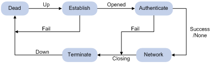
1. Initially, PPP is in Link Dead phase. After the physical layer goes up, PPP enters the Link Establishment phase (Establish).
2. In the Link Establishment phase, the LCP negotiation is performed. The LCP configuration options include Authentication-Protocol, Async-Control-Character-Map (ACCM), Maximum-Receive-Unit (MRU), Magic-Number, Protocol-Field-Compression (PFC), Address-and-Control-Field-Compression (ACFC), and MP.
? If the negotiation fails, LCP reports a Fail event, and PPP returns to the Dead phase.
? If the negotiation succeeds, LCP enters the Opened state and reports an Up event, indicating that the underlying layer link has been established. At this time, the PPP link is not established for the network layer, and network layer packets cannot be transmitted over the link.
3. If authentication is configured, the PPP link enters the Authentication phase, where PAP, CHAP, MS-CHAP, or MS-CHAP-V2 authentication is performed.
? If the client fails to pass the authentication, LCP reports a Fail event and enters the Link Termination phase. In this phase, the link is torn down and LCP goes down.
? If the client passes the authentication, LCP reports a Success event.
4. If a network layer protocol is configured, the PPP link enters the Network-Layer Protocol phase for NCP negotiation, such as IPCP negotiation and IPv6CP negotiation.
? If the NCP negotiation succeeds, the link goes up and becomes ready to carry negotiated network-layer protocol packets.
? If the NCP negotiation fails, NCP reports a Down event and enters the Link Termination phase.
If the interface is configured with an IP address, the IPCP negotiation is performed. IPCP configuration options include IP addresses and DNS server IP addresses. After the IPCP negotiation succeeds, the link can carry IP packets.
5. After the NCP negotiation is performed, the PPP link remains active until either of the following events occurs:
? Explicit LCP or NCP frames close the link.
? Some external events take place (for example, the intervention of a user).
For more information about PPP, see RFC 1661.
PPP authentication
PPP supports the following authentication methods:
· PAP—PAP is a two-way handshake authentication protocol using the username and password.
PAP sends username/password pairs in plain text over the network. If authentication packets are intercepted in transit, network security might be threatened. For this reason, it is suitable only for low-security environments.
· CHAP—CHAP is a three-way handshake authentication protocol.
CHAP transmits usernames but not passwords over the network. It transmits the result calculated from the password and random packet ID by using the MD5 algorithm. It is more secure than PAP. The authenticator may or may not be configured with a username. H3C recommends that you configure a username for the authenticator, which makes it easier for the peer to verify the identity of the authenticator.
· MS-CHAP—MS-CHAP is a three-way handshake authentication protocol.
MS-CHAP differs from CHAP as follows:
? MS-CHAP uses CHAP Algorithm 0x80.
? MS-CHAP provides authentication retry. If the peer fails authentication, it is allowed to retransmit authentication information to the authenticator for reauthentication. The authenticator allows a peer to retransmit a maximum of three times.
· MS-CHAP-V2—MS-CHAP-V2 is a three-way handshake authentication protocol.
MS-CHAP-V2 differs from CHAP as follows:
? MS-CHAP-V2 uses CHAP Algorithm 0x81.
? MS-CHAP-V2 provides two-way authentication by piggybacking a peer challenge on the Response packet and an authenticator response on the Acknowledge packet.
? MS-CHAP-V2 supports authentication retry. If the peer fails authentication, it is allowed to retransmit authentication information to the authenticator for reauthentication. The authenticator allows a peer to retransmit a maximum of three times.
? MS-CHAP-V2 supports password change. If the peer fails authentication because of an expired password, it will send the new password entered by the user to the authenticator for reauthentication.
PPP for IPv4
On IPv4 networks, PPP negotiates the IP address and DNS server address during IPCP negotiation.
IP address negotiation
IP address negotiation enables one end to assign an IP address to the other.
An interface can act as a client or a server during IP address negotiation:
· Client—Obtains an IP address from the server. Use the client mode when the device accesses the Internet through an ISP.
· Server—Assigns an IP address to the client. Before you configure the IP address of the server, you must perform one of the following tasks:
? Configure a local address pool and associate the pool with the ISP domain.
? Specify an IP address or an address pool for the client on the interface.
When IP address negotiation is enabled on a client, the server selects an IP address for the client in the following sequence:
1. If the AAA server configures an IP address or address pool for the client, the server selects that IP address or an IP address from the pool. The IP address or address pool is configured on the AAA server instead of the PPP server. For information about AAA, see Security Configuration Guide.
2. If an address pool is associated with the ISP domain used during client authentication, the server selects an IP address from the pool.
3. If an IP address or address pool is specified for the client on the interface of the server, the server selects that IP address or an IP address from that pool.
DNS server address negotiation
IPCP negotiation can determine the DNS server IP address.
When the device is connected to a host, configure the device as the server to assign the DNS server IP address to the host.
When the device is connected to an ISP access server, configure the device as the client. Then, the device can obtain the DNS server IP address from the ISP access server.
PPP for IPv6
On IPv6 networks, PPP negotiates only the IPv6 interface identifier instead of the IPv6 address and IPv6 DNS server address during IPv6CP negotiation.
IPv6 address assignment
PPP cannot negotiate the IPv6 address.
The client can get an IPv6 global unicast address through the following methods:
· Method 1—The client obtains an IPv6 prefix in an RA message. The client then generates an IPv6 global unicast address by combining the IPv6 prefix and the negotiated IPv6 interface identifier. The IPv6 prefix in the RA message is determined in the following sequence:
? IPv6 prefix authorized by AAA.
? RA prefix configured on the interface.
? Prefix of the IPv6 global unicast address configured on the interface.
For information about the ND protocol, see Layer 3—IP Services Configuration Guide.
· Method 2—The client requests an IPv6 global unicast address through DHCPv6. The server assigns an IPv6 address to the client from the address pool authorized by AAA. If no AAA-authorized address pool exists, DHCPv6 uses the address pool that matches the server's IPv6 address to assign an IPv6 address to the client.
· Method 3—The client requests prefixes through DHCPv6 and assigns them to downstream hosts. The hosts then uses the prefixes to generate global IPv6 addresses. This method uses the same principle of selecting address pools as method 2.
The device can assign a host an IPv6 address in either of the following ways:
· When the host connects to the device directly or through a bridge device, the device can use method 1 or method 2.
· When the host accesses the device through a router, the device can use method 3 to assign an IPv6 prefix to the router. The router assigns the prefix to the host to generate an IPv6 global unicast address.
IPv6 DNS server address assignment
On IPv6 networks, two methods are available for the IPv6 DNS address assignment:
· AAA authorizes the IPv6 DNS address and assigns this address to the host through RA messages.
· The DHCPv6 client requests an IPv6 DNS address from the DHCPv6 server.
PPP configuration task list
|
Tasks at a glance |
|
(Optional.) Configuring PPP authentication |
|
(Optional.) Configuring the polling feature |
|
(Optional.) Configuring PPP negotiation |
|
(Optional.) Enabling IP header compression |
|
(Optional.) Enabling PPP accounting |
|
(Optional.) Configuring the nas-port-type attribute |
Configuring PPP authentication
You can configure several authentication modes simultaneously. In LCP negotiation, the authenticator negotiates with the peer in the sequence of configured authentication modes until the LCP negotiation succeeds. If the response packet from the peer carries a recommended authentication mode, the authenticator directly uses the authentication mode if it finds the mode configured.
Configuring PAP authentication
To configure the authenticator:
|
Step |
Command |
Remarks |
|
1. Enter system view. |
system-view |
N/A |
|
2. Enter interface view. |
interface interface-type interface-number |
N/A |
|
3. Configure the authenticator to authenticate the peer by using PAP. |
ppp authentication-mode pap [ [ call-in ] domain isp-name ] |
By default, PPP authentication is disabled. |
|
4. Configure local or remote AAA authentication. |
For local AAA authentication, the username and password of the peer must be configured on the authenticator. For remote AAA authentication, the username and password of the peer must be configured on the remote AAA server. For more information about AAA authentication, see Security Configuration Guide. |
The username and password configured for the peer must be the same as those configured on the peer. By default, ciphertext and plaintext passwords are displayed in cipher text. |
To configure the peer:
|
Step |
Command |
Remarks |
|
1. Enter system view. |
system-view |
N/A |
|
2. Enter interface view. |
interface interface-type interface-number |
N/A |
|
3. Configure the PAP username and password sent from the peer to the authenticator when the peer is authenticated by the authenticator by using PAP. |
ppp pap local-user username password { cipher | simple } password |
By default, when being authenticated by the authenticator by using PAP, the peer sends null username and password to the authenticator. |
Configuring CHAP authentication
Depending on whether the authenticator is configured with a username, the configuration of CHAP authentication includes the following types:
· Configuring CHAP authentication when the authenticator name is configured
To configure the authenticator:
|
Step |
Command |
Remarks |
|
1. Enter system view. |
system-view |
N/A |
|
2. Enter interface view. |
interface interface-type interface-number |
N/A |
|
3. Configure the authenticator to authenticate the peer by using CHAP. |
ppp authentication-mode chap [ [ call-in ] domain isp-name ] |
By default, PPP authentication is disabled. |
|
4. Configure a username for the CHAP authenticator. |
ppp chap user username |
The default setting is null. The username you configure for the authenticator must be the same as the local username you configure for the authenticator on the peer. |
|
5. Configure local or remote AAA authentication. |
For local AAA authentication, the username and password of the peer must be configured on the authenticator. For remote AAA authentication, the username and password of the peer must be configured on the remote AAA server. For more information about AAA authentication, see Security Configuration Guide. |
The username configured for the peer must be the same as that configured on the peer. The passwords configured for the authenticator and peer must be the same. |
To configure the peer:
|
Step |
Command |
Remarks |
|
1. Enter system view. |
system-view |
N/A |
|
2. Enter interface view. |
interface interface-type interface-number |
N/A |
|
3. Configure a username for the CHAP peer. |
ppp chap user username |
The default setting is null. The username you configure for the peer here must be the same as the local username you configure for the peer on the authenticator. |
|
4. Configure local or remote AAA authentication. |
For local AAA authentication, the username and password of the authenticator must be configured on the peer. For remote AAA authentication, the username and password of the authenticator must be configured on the remote AAA server. For more information about AAA authentication, see Security Configuration Guide. |
The username configured for the authenticator must be the same as that configured on the authenticator. The passwords configured for the authenticator and peer must be the same. |
· Configuring CHAP authentication when no authenticator name is configured
To configure the authenticator:
|
Step |
Command |
Remarks |
|
1. Enter system view. |
system-view |
N/A |
|
2. Enter interface view. |
interface interface-type interface-number |
N/A |
|
3. Configure the authenticator to authenticate the peer by using CHAP. |
ppp authentication-mode chap [ [ call-in ] domain isp-name ] |
By default, PPP authentication is disabled. |
|
4. Configure local or remote AAA authentication. |
For local AAA authentication, the username and password of the peer must be configured on the authenticator. For remote AAA authentication, the username and password of the peer must be configured on the remote AAA server. For more information about AAA authentication, see Security Configuration Guide. |
The username configured for the peer must be the same as that configured on the peer. The passwords configured for the authenticator and peer must be the same. |
To configure the peer:
|
Step |
Command |
Remarks |
|
1. Enter system view. |
system-view |
N/A |
|
2. Enter interface view. |
interface interface-type interface-number |
N/A |
|
3. Configure a username for the CHAP peer. |
ppp chap user username |
The default setting is null. The username you configure on the peer must be the same as the local username you configure for the peer on the authenticator. |
|
4. Set the CHAP authentication password. |
ppp chap password { cipher | simple } password |
The default setting is null. The password you set on the peer must be the same as the password you set for the peer on the authenticator. By default, ciphertext and plaintext passwords are displayed in cipher text. |
Configuring MS-CHAP or MS-CHAP-V2 authentication
When you configure MS-CHAP or MS-CHAP-V2 authentication, follow these guidelines:
· The device can only act as an authenticator for MS-CHAP or MS-CHAP-V2 authentication.
· L2TP supports only MS-CHAP authentication.
· MS-CHAP-V2 authentication supports password change only when using RADIUS.
To configure MS-CHAP or MS-CHAP-V2 authentication when the authenticator name is configured:
|
Step |
Command |
Remarks |
|
1. Enter system view. |
system-view |
N/A |
|
2. Enter interface view. |
interface interface-type interface-number |
N/A |
|
3. Configure the authenticator to authenticate the peer by using MS-CHAP or MS-CHAP-V2. |
ppp authentication-mode { ms-chap | ms-chap-v2 } [ [ call-in ] domain isp-name ] |
By default, PPP authentication is disabled. |
|
4. Configure a username for the MS-CHAP or MS-CHAP-V2 authenticator. |
ppp chap user username |
The username for the authenticator must be the same on the local and peer devices. |
|
5. Configure local or remote AAA authentication. |
For local AAA authentication, the username and password of the peer must be configured on the authenticator. For remote AAA authentication, the username and password of the peer must be configured on the remote AAA server. For more information about AAA authentication, see Security Configuration Guide. |
The username and password of the peer configured on the authenticator or remote AAA server must be the same as those configured on the peer. |
To configure MS-CHAP or MS-CHAP-V2 authentication when no authenticator name is configured:
|
Step |
Command |
Remarks |
|
1. Enter system view. |
system-view |
N/A |
|
2. Enter interface view. |
interface interface-type interface-number |
N/A |
|
3. Configure the authenticator to authenticate the peer by using MS-CHAP or MS-CHAP-V2. |
ppp authentication-mode { ms-chap | ms-chap-v2 } [ [ call-in ] domain isp-name ] |
By default, PPP authentication is disabled. |
|
4. Configure local or remote AAA authentication. |
For local AAA authentication, the username and password of the peer must be configured on the authenticator. For remote AAA authentication, the username and password of the peer must be configured on the remote AAA server. For more information about AAA authentication, see Security Configuration Guide. |
The username and password of the peer configured on the authenticator or remote AAA server must be the same as those configured on the peer. |
Configuring the polling feature
The polling feature checks PPP link state.
On an interface that uses PPP encapsulation, the link layer sends keepalives at keepalive intervals to detect the availability of the peer. If the interface fails to receive keepalives when the keepalive retry limit is reached, it tears down the link and reports a link layer down event.
To set the keepalive retry limit, use the timer-hold retry command.
On a slow link, increase the keepalive interval to prevent false shutdown of the interface. This situation might occur when keepalives are delayed because a large packet is being transmitted on the link.
To disable sending of keepalives, set the keepalive interval to 0.
To configure the polling feature:
|
Step |
Command |
Remarks |
|
1. Enter system view. |
system-view |
N/A |
|
2. Enter interface view. |
interface interface-type interface-number |
N/A |
|
3. Set the keepalive interval. |
timer-hold seconds |
The default setting is 10 seconds. |
|
4. Set the keepalive retry limit. |
timer-hold retry retry |
The default setting is 5. |
Configuring PPP negotiation
PPP negotiation includes the following parameters:
· Negotiation timeout time.
· IP address negotiation.
· IP segment match.
· DNS server IP address negotiation.
Configuring the PPP negotiation timeout time
The device starts the PPP negotiation timeout timer after sending a packet. If no response is received before the timer expires, the device sends the packet again.
If two ends of a PPP link vary greatly in the LCP negotiation packet processing rate, configure the delay timer on the end with a higher processing rate. The LCP negotiation delay timer prevents frequent LCP negotiation packet retransmissions. After the physical layer comes up, PPP starts LCP negotiation when the delay timer expires. If PPP receives LCP negotiation packets before the delay timer expires, it starts LCP negotiation immediately.
To configure the PPP negotiation timeout time:
|
Step |
Command |
Remarks |
|
1. Enter system view. |
system-view |
N/A |
|
2. Enter interface view. |
interface interface-type interface-number |
N/A |
|
3. Configure the negotiation timeout time. |
ppp timer negotiate seconds |
The default setting is 3 seconds. |
|
4. (Optional.) Configure the LCP negotiation delay timer. |
ppp lcp delay milliseconds |
By default, PPP starts LCP negotiation after the physical layer is up. |
Configuring IP address negotiation
To configure the device as the client:
|
Step |
Command |
Remarks |
|
1. Enter system view. |
system-view |
N/A |
|
2. Enter interface view. |
interface interface-type interface-number |
N/A |
|
3. Enable IP address negotiation. |
ip address ppp-negotiate |
By default, IP address negotiation is not enabled. This command is mutually exclusive with the ip address command. For more information about the ip address command, see Layer 3—IP Services Command Reference. |
Configure the server to assign an IP address to a client by using the following methods:
· Method 1: Specify an IP address for the client on the server interface.
· Method 2: Specify a PPP or DHCP address pool on the server interface.
· Method 3: Associate a PPP or DHCP address pool with an ISP domain.
For clients requiring no authentication, you can use either method 1 or method 2, but not both.
For clients requiring authentication, you can use one or more of the three methods, but cannot use method 1 and method 2 at the same time. When multiple methods are configured, method 3 takes precedence over method 1 or method 2.
PPP supports IP address assignment from a PPP or DHCP address pool. If you use a pool name that identifies both a PPP address pool and a DHCP address pool, the system uses the PPP address pool.
To configure the device as the server (Method 1):
|
Step |
Command |
Remarks |
|
1. Enter system view. |
system-view |
N/A |
|
2. Enter interface view. |
interface interface-type interface-number |
N/A |
|
3. Configure the interface to assign an IP address to the peer. |
remote address ip-address |
By default, an interface does not assign an IP address to the peer. |
|
4. Configure an IP address for the interface. |
ip address ip-address |
By default, no IP address is configured on an interface. |
To configure the device as the server (Method 2: Specify a PPP address pool):
|
Step |
Command |
Remarks |
|
1. Enter system view. |
system-view |
N/A |
|
2. Configure a PPP address pool. |
ip pool pool-name start-ip-address [ end-ip-address ] [ group group-name ] |
By default, no PPP address pool is configured. |
|
3. (Optional.) Configure a gateway address for the PPP address pool. |
ip pool pool-name gateway ip-address |
By default, the PPP address pool is not configured with a gateway address. |
|
4. (Optional.) Configure a PPP address pool route. |
ppp ip-pool route ip-address { mask-length | mask } |
By default, no PPP address pool route exists. The destination network of the PPP address pool route must include the PPP address pool. |
|
5. Enter interface view. |
interface interface-type interface-number |
N/A |
|
6. Configure the interface to assign an IP address from the configured PPP address pool to the peer. |
remote address pool pool-name |
By default, an interface does not assign an IP address to the peer. |
|
7. Configure an IP address for the interface. |
ip address ip-address |
By default, no IP address is configured on an interface. This command is optional when the PPP address pool has been configured with a gateway address. |
To configure the device as the server (Method 2: Specify a DHCP address pool):
|
Step |
Command |
Remarks |
|
1. Enter system view. |
system-view |
N/A |
|
2. Enter interface view. |
interface interface-type interface-number |
N/A |
|
3. Configure the interface to assign an IP address from the configured DHCP address pool to the peer. |
remote address pool pool-name |
By default, an interface does not assign an IP address to the peer. |
|
4. Configure an IP address for the interface. |
ip address ip-address |
By default, no IP address is configured on an interface. |
|
5. (Optional.) Use the PPP usernames as the DHCP client IDs. |
remote address dhcp client-identifier username |
By default, the PPP usernames are not used as the DHCP client IDs. |
To configure the device as the server (Method 3: Associate a PPP address pool with an ISP domain):
|
Step |
Command |
Remarks |
|
1. Enter system view. |
system-view |
N/A |
|
2. Configure a PPP address pool. |
ip pool pool-name start-ip-address [ end-ip-address ] [ group group-name ] |
By default, no PPP address pool is configured. |
|
3. (Optional.) Configure a gateway address for the PPP address pool. |
ip pool pool-name gateway ip-address |
By default, the PPP address pool is not configured with a gateway address. |
|
4. (Optional.) Configure a PPP address pool route. |
ppp ip-pool route ip-address { mask-length | mask } |
By default, no PPP address pool route exists. The destination network of the PPP address pool route must include the PPP address pool. |
|
5. Enter ISP domain view. |
domain isp-name |
N/A |
|
6. Associate the ISP domain with the configured PPP address pool for address assignment. |
authorization-attribute ip-pool pool-name |
By default, no PPP address pool is associated. For more information about this command, see Security Command Reference. |
|
7. Return to system view. |
quit |
N/A |
|
8. Enter interface view. |
interface interface-type interface-number |
N/A |
|
9. Configure an IP address for the interface. |
ip address ip-address |
By default, no IP address is configured on an interface. This command is optional when the PPP address pool is configured with a gateway address. |
To configure the device as the server (Method 3: Associate a DHCP address pool with an ISP domain):
|
Step |
Command |
Remarks |
|
1. Enter system view. |
system-view |
N/A |
|
2. Associate the ISP domain with the configured DHCP address pool for address assignment. |
authorization-attribute ip-pool pool-name |
By default, no DHCP address pool is associated. For more information about this command, see Security Command Reference. |
|
3. Return to system view. |
quit |
N/A |
|
4. Enter interface view. |
interface interface-type interface-number |
N/A |
|
5. Configure an IP address for the interface. |
ip address ip-address |
By default, no IP address is configured on an interface. |
|
6. (Optional.) Use the PPP usernames as the DHCP client IDs. |
remote address dhcp client-identifier username |
By default, the PPP usernames are not used as the DHCP client IDs. |
Enabling IP segment match
This feature enables the local interface to check whether its IP address and the IP address of the remote interface are in the same network segment. If they are not, IPCP negotiation fails.
To enable IP segment match:
|
Step |
Command |
Remarks |
|
1. Enter system view. |
system-view |
N/A |
|
2. Enter interface view. |
interface interface-type interface-number |
N/A |
|
3. Enable IP segment match. |
ppp ipcp remote-address match |
By default, this feature is disabled. |
Configuring DNS server IP address negotiation
Configure DNS server settings depending on the role of your device in PPP negotiation.
· Configuring the local end as the client
During PPP negotiation, the server will assign a DNS server IP address only for a client configured with the ppp ipcp dns request command. For some special devices to forcibly assign DNS server IP addresses to clients that do not initiate requests, configure the ppp ipcp dns admit-any command on these devices.
To configure the local end as the client:
|
Step |
Command |
Remarks |
|
1. Enter system view. |
system-view |
N/A |
|
2. Enter interface view. |
interface interface-type interface-number |
N/A |
|
3. Enable the device to request the peer for a DNS server IP address. |
ppp ipcp dns request |
By default, a client does not request its peer for a DNS server IP address. |
|
4. Configure the device to accept the DNS server IP addresses assigned by the peer even though it does not request the peer for the DNS server IP addresses. |
ppp ipcp dns admit-any |
By default, a device does not accept the DNS server IP addresses assigned by the peer if it does not request the peer for the DNS server IP addresses. This command is not necessary if the ppp ipcp dns request command is configured. |
· Configuring the local end as the server
|
Step |
Command |
Remarks |
|
1. Enter system view. |
system-view |
N/A |
|
2. Enter interface view. |
interface interface-type interface-number |
N/A |
|
3. Specify the primary and secondary DNS server IP addresses to be allocated to the peer in PPP negotiation. |
ppp ipcp dns primary-dns-address [ secondary-dns-address ] |
By default, a device does not allocate DNS server IP addresses to its peer if the peer does not request them. |
Enabling IP header compression
IP header compression (IPHC) compresses packet headers to speed up packet transmission. IPHC is often used for voice communications over low-speed links.
IPHC provides the following compression features:
· RTP header compression—Compresses the IP header, UDP header, and RTP header of an RTP packet, which have a total length of 40 bytes.
· TCP header compression—Compresses the IP header and TCP header of a TCP packet, which have a total length of 40 bytes.
To use IPHC, you must enable it on both sides of a PPP link.
Enabling or disabling IPHC on a VT or dialer interface does not immediately take effect. You must execute the shutdown and undo shutdown commands on the interface or the bound physical interface to apply the new setting.
After you enable IPHC, you can configure the maximum number of connections for RTP or TCP header compression. The configuration takes effect after you execute the shutdown and undo shutdown command on the interface. The configuration is removed after IPHC is disabled.
To configure IPHC:
|
Step |
Command |
Remarks |
|
1. Enter system view. |
system-view |
N/A |
|
2. Enter interface view. |
interface interface-type interface-number |
N/A |
|
3. Enable IP header compression. |
ppp compression iphc enable [ nonstandard ] |
By default, IP header compression is disabled. The nonstandard option must be specified when the device communicates with a non-H3C device. |
|
4. Set the maximum number of connections for which an interface can perform RTP header compression. |
ppp compression iphc rtp-connections number |
The default setting is 16. |
|
5. Set the maximum number of connections for which an interface can perform TCP header compression. |
ppp compression iphc tcp-connections number |
The default setting is 16. |
Enabling PPP accounting
PPP accounting collects PPP statistics, including the numbers of received and sent PPP packets and bytes. AAA can use the PPP statistics for accounting. For more information about AAA, see Security Configuration Guide.
To enable PPP accounting:
|
Step |
Command |
Remarks |
|
1. Enter system view. |
system-view |
N/A |
|
2. Enter interface view. |
interface interface-type interface-number |
N/A |
|
3. Enable PPP accounting. |
ppp account-statistics enable [ acl { acl-number | name acl-name } ] |
By default, PPP accounting is disabled. |
Configuring the nas-port-type attribute
The nas-port-type attribute is used for RADIUS authentication and accounting. For information about the nas-port-type attribute, see RFC 2865.
To configure the nas-port-type attribute:
|
Step |
Command |
Remarks |
|
1. Enter system view. |
system-view |
N/A |
|
2. Enter VT interface view. |
interface virtual-template number |
N/A |
|
3. Configure the nas-port-type attribute. |
nas-port-type { 802.11 | adsl-cap | adsl-dmt | async | cable | ethernet | g.3-fax | hdlc | idsl | isdn-async-v110 | isdn-async-v120 | isdn-sync | piafs | sdsl | sync | virtual | wireless-other | x.25 | x.75 | xdsl } |
By default, the nas-port-type attribute is determined by the service type and link type of the PPP user (see Table 1). |
Table 1 Default nas-port-type attribute
|
Service type |
Link type |
Nas-port-type attribute |
|
PPPoE |
Layer 3 virtual Ethernet interface |
xdsl |
|
Other interfaces |
ethernet |
|
|
PPPoA |
Any |
xdsl |
|
L2TP |
Any |
virtual |
Displaying and maintaining PPP
Execute display commands in any view and reset commands in user view.
|
Task |
Command |
|
Display information about PPP access users. |
display ppp access-user { interface interface-type interface-number [ count ] | ip-address ip-address | ipv6-address ipv6-address | username user-name | user-type { lac | lns | pppoa | pppoe } [ count ] } |
|
Display PPP address pools. |
display ip pool [ pool-name ] [ group group-name ] |
|
Display IPHC statistics. |
display ppp compression iphc { rtp | tcp } [ interface interface-type interface-number ] |
|
Display information about VT interfaces. |
display interface [ virtual-template [ interface-number ] ] [ brief [ description | down ] ] |
|
Display information about VA interfaces on a VT interface. |
display interface [ virtual-access [ interface-number ] ] [ brief [ description | down ] ] |
|
Clear IPHC statistics. |
reset ppp compression iphc [ rtp | tcp ] [ interface interface-type interface-number ] |
|
Log off a PPP user. |
reset ppp access-user { ip-address ip-address | ipv6-address ipv6-address | username user-name } |
|
Clear the statistics for VA interfaces. |
reset counters interface [ virtual-access [ interface-number ] ] |
Configuring PPPoE
Point-to-Point Protocol over Ethernet (PPPoE) extends PPP by transporting PPP frames encapsulated in Ethernet over point-to-point links.
PPPoE specifies the methods for establishing PPPoE sessions and encapsulating PPP frames over Ethernet. PPPoE requires a point-to-point relationship between peers instead of a point-to-multipoint relationship as in multi-access environments such as Ethernet. PPPoE provides Internet access for the hosts in an Ethernet through a remote access device and implement access control, authentication, and accounting on a per-host basis. Integrating the low cost of Ethernet and scalability and management functions of PPP, PPPoE gained popularity in various application environments, such as residential access networks.
For more information about PPPoE, see RFC 2516.
PPPoE network structure
PPPoE uses the client/server model. The PPPoE client initiates a connection request to the PPPoE server. After session negotiation between them is complete, a session is established between them, and the PPPoE server provides access control, authentication, and accounting to the PPPoE client.
Depending on the starting point of the PPPoE session, the following network structures are available:
· As shown in Figure 2, the PPPoE session is established between routers (Router A and Router B). All hosts share one PPPoE session for data transmission without being installed with PPPoE client software. This network structure is typically used by enterprises.
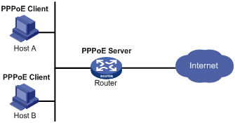
· As shown in Figure 3, a PPPoE session is established between each host (PPPoE client) and the carrier router (PPPoE server). The service provider assigns an account to each host for billing and control. The host must be installed with PPPoE client software.
Restrictions: Command and hardware compatibility
The WX1800H series access controllers do not support the slot keyword or the slot-number argument.
Configuring the PPPoE server
Configuring a PPPoE session
|
Step |
Command |
Remarks |
|
1. Enter system view. |
system-view |
N/A |
|
2. Create a VT interface and enter VT interface view. |
interface virtual-template number |
N/A |
|
3. Set PPP parameters. |
See "Configuring PPP." |
If authentication is needed, use the PPPoE server as the authenticator. |
|
4. Enable MRU verification. |
ppp lcp echo mru verify [ minimum value ] |
By default, MRU verification is disabled. |
|
5. Return to system view. |
quit |
N/A |
|
6. Enter VLAN interface view. |
interface interface-type interface-number |
N/A |
|
7. Enable the PPPoE server on the interface and bind this interface to the specified VT interface. |
pppoe-server bind virtual-template number |
By default, the PPPoE server is disabled on the interface. |
|
8. (Optional.) Configure an access controller (AC) name for the PPPoE server. |
pppoe-server tag ac-name name |
By default, the AC name for the PPPoE server is the device name. PPPoE clients can choose a PPPoE server according to the AC name. The PPPoE client on H3C devices do not support this feature. |
|
9. (Optional.) Enable the PPPoE server to support the ppp-max-payload tag and specify a range for the PPP maximum payload. |
pppoe-server tag ppp-max-payload [ minimum minvalue maximum maxvalue ] |
By default, The PPPoE server does not support the ppp-max-payload tag. |
|
10. (Optional.) Set a service name for the PPPoE server |
pppoe-server tag service-name name |
By default, the PPPoE server does not have a service name. |
|
11. (Optional) Set the response delay time for user access. |
pppoe-server access-delay delay-time |
By default, no response delay time is set. |
|
12. Return to system view. |
quit |
N/A |
|
13. Configure the PPPoE server to perform authentication, authorization, and accounting for PPP users. |
See Security Configuration Guide. |
N/A |
Setting the maximum number of PPPoE sessions
PPPoE can establish a session when none of the following maximum numbers are reached:
· The maximum number of PPPoE sessions for a user on an interface.
· The maximum number of PPPoE sessions for a VLAN on an interface.
· The maximum number of PPPoE sessions on an interface.
· The maximum number of PPPoE sessions on an IRF member device.
New maximum number settings apply only to subsequently established PPPoE sessions.
The total maximum number of PPPoE sessions set for all IRF member devices cannot be set greater than the maximum number of PPPoE sessions supported by the device.
To configure the maximum number of PPPoE sessions:
|
Step |
Command |
Remarks |
|
1. Enter system view. |
system-view |
N/A |
|
2. Enter VLAN interface view. |
interface interface-type interface-number |
The PPPoE server is enabled on the interface. |
|
3. Set the maximum number of PPPoE sessions on the interface. |
pppoe-server session-limit number |
By default, the number of PPPoE sessions on an interface is not limited. |
|
4. Set the maximum number of PPPoE sessions for a VLAN on an interface. |
pppoe-server session-limit per-vlan number |
By default, the number of PPPoE sessions for a VLAN on an interface is not limited. |
|
5. Set the maximum number of PPPoE sessions for a user on the interface. |
pppoe-server session-limit per-mac number |
By default, a user is allowed to create a maximum of 100 PPPoE sessions. |
|
6. Return to system view. |
quit |
N/A |
|
7. Set the maximum number of PPPoE sessions on the IRF member device. |
pppoe-server session-limit slot slot-number total number |
By default, the number of PPPoE sessions on an IRF member device is not limited. |
Limiting the PPPoE access rate
The device can limit the rate at which a user (identified by an MAC address) can create PPPoE sessions on an interface. If the number of PPPoE requests within the monitoring time exceeds the configured threshold, the device discards the excessive requests, and outputs log messages. If the blocking time is set to 0, the device does not block any requests, and it only outputs log messages.
The device uses a monitoring table and a blocking table to control PPP access rates:
· Monitoring table—Stores a maximum of 8000 monitoring entries. Each entry records the number of PPPoE sessions created by a user within the monitoring time. When the monitoring entries reach the maximum, the system stops monitoring and blocking session requests from new users. The aging time of monitoring entries is determined by the session-request-period argument. When the timer expires, the system starts a new round of monitoring for the user.
· Blocking table—Stores a maximum of 8000 blocking entries. The system creates a blocking entry if the access rate of a user reaches the threshold, and blocks requests from that user. When the blocking entries reach the maximum number, the system stops blocking session requests from new users and it only outputs log messages. The aging time of the blocking entries is determined by the blocking-period argument. When the timer expires, the system starts a new round of monitoring for the user.
If the access rate setting is changed, the system removes all monitoring and blocking entries, and uses the new settings to limit PPPoE access rates.
To limit the PPPoE access rate:
|
Step |
Command |
Remarks |
|
1. Enter system view. |
system-view |
N/A |
|
2. Enter VLAN interface view. |
interface interface-type interface-number |
The PPPoE server is enabled on the interface. |
|
3. Set the PPPoE access limit. |
pppoe-server throttle per-mac session-requests session-request-period blocking-period |
By default, the PPPoE access rate is not limited. |
|
4. Display information about blocked users. |
display pppoe-server throttled-mac { slot slot-number | interface interface-type interface-number } |
Available in any view. |
Configuring the nas-port-id attribute
The PPPoE server on a BAS device uses the RADIUS nas-port-id attribute to send the access line ID received from a DSLAM device to the RADIUS server. The access line ID includes the circuit-id and remote-id. The RADIUS server compares the received nas-port-id attribute with the local line ID information to verify the location of the user.
You can configure the content of the nas-port-id attribute that the PPPoE server sends to the RADIUS server.
To configure the nas-port-id attribute:
|
Step |
Command |
Remarks |
|
1. Enter system view. |
system-view |
N/A |
|
2. Enter VLAN interface view. |
interface interface-type interface-number |
The PPPoE server is enabled on the interface. |
|
3. Configure the content of the nas-port-id attribute. |
pppoe-server access-line-id content { all [ separator ] | circuit-id | remote-id } |
By default, the nas-port-id attribute contains only the circuit-id. |
|
4. Configure the nas-port-id attribute to include the BAS information automatically. |
pppoe-server access-line-id bas-info [ cn-163 ] |
By default, the nas-port-id attribute does not include the BAS information automatically. |
|
5. Configure the PPPoE server to trust the access line ID in received packets. |
pppoe-server access-line-id trust |
By default, the PPPoE server does not trust the access line ID in received packets. |
|
6. Configure the format that is used to parse the circuit-id. |
pppoe-server access-line-id circuit-id parse-mode { cn-telecom | tr-101 } |
The default mode is TR-101. |
|
7. Configure the transmission format for the circuit-id. |
pppoe-server access-line-id circuit-id trans-format { ascii | hex } |
The default format is a string of characters. |
|
8. Configure the transmission format for the remote-id. |
pppoe-server access-line-id remote-id trans-format { ascii | hex } |
The default format is a string of characters. |
Configuring a VA pool
The PPPoE server creates a VA interface for a PPPoE session to transmit packets between PPPoE and PPP. It removes the VA interface when the user goes offline. Creating and removing VA interfaces take time. If a large number of users are going online or offline, the performance of PPPoE session establishment and termination will be degraded.
You can configure a VA pool to improve the performance. A VA pool contains a group of VA interfaces. The PPPoE server selects a VA interface from the pool for a requesting user and release the VA interface when the user goes offline. This feature speeds up the establishment and termination of PPPoE sessions. When a VA pool is exhausted, the system creates a VA interface for a PPPoE session, and removes it when the user goes offline.
When you configure a VA pool, follow these guidelines:
· A VT interface can be associated with only one global VA pool, and an IRF member device can be associated with only one regional VA pool. Users on an Ethernet interface can only use the VA pool associated with the VT interface that is bound to the Ethernet interface. To change the capacity for a VA pool, delete the previous configuration, and reconfigure the VA pool.
· Creating or removing a VA pool takes time. During the process of creating or removing a VA pool, users can go online or offline, but the VA pool does not take effect.
· The system might create a VA pool that contains VA interfaces less than the specified number because of insufficient resources. In this case, you can use the display pppoe-server va-pool command to view the number of available VA interfaces and current state of the VA pool.
· Deleting a VA pool does not log off the users who are using VA interfaces in the VA pool.
To configure a VA pool:
|
Step |
Command |
Remarks |
|
1. Enter system view. |
system-view |
N/A |
|
2. Create a VA pool. |
pppoe-server virtual-template template-number [ slot slot-number ] va-pool va-volume |
By default, no VA pool exists. |
Clearing PPPoE sessions
To clear PPPoE sessions on the PPPoE server:
|
Step |
Command |
Remarks |
|
1. Enter user view. |
user-view |
N/A |
|
2. Clear PPPoE sessions. |
reset pppoe-server { all | interface interface-type interface-number | virtual-template number } |
N/A |
Configuring a PPPoE client
PPPoE client configuration includes dialer interface configuration and PPPoE session configuration.
A PPPoE session can operate in one of the following modes:
· Permanent mode—A PPPoE session is established immediately when the line is physically up. This type of session remains until the physical link comes down or until the session is disconnected.
· On-demand mode—A PPPoE session is established when there is a demand for data transmission instead of when the line is physically up. It is terminated when idled for a specific period of time.
· Diagnostic mode—A PPPoE session is established immediately after the device configurations finish. The device automatically terminates the PPPoE session and then tries to re-establish a PPPoE session at a pre-configured interval. By establishing and terminating PPPoE sessions periodically, you can monitor the operating status of the PPPoE link.
The PPPoE session operating mode is determined by your configuration on the dialer interface:
· Permanent mode—Used when you set the link idle time to 0 by using the dialer timer idle command and do not configure the dialer diagnose command.
· On-demand mode—Used when you set the link idle time to a non-zero value by using the dialer timer idle command and do not configure the dialer diagnose command.
· Diagnostic mode—Used when you configure the dialer diagnose command.
Hardware compatibility with PPPoE client
|
Hardware series |
Model |
Feature compatibility |
|
WX1800H series |
WX1804H WX1810H WX1820H WX1840H |
Yes |
|
WX3800H series |
WX3820H WX3840H |
No |
|
WX5800H series |
WX5860H |
No |
Configuring a dialer interface
Before establishing a PPPoE session, you must first create a dialer interface and configure bundle DDR on the interface. Each PPPoE session uniquely corresponds to a dialer bundle, and each dialer bundle uniquely corresponds to a dialer interface. A PPPoE session uniquely corresponds to a dialer interface.
Configuring a dialer interface for a PPPoE client
|
Step |
Command |
Remarks |
|
1. Enter system view. |
system-view |
N/A |
|
2. Create a dialer access group and configure a dial access control rule. |
dialer-group dialer-group rule { protocol-name { deny | permit } | acl { acl-number | name acl-number } |
By default, no dialer group exists. |
|
3. Create a dialer interface and enter its view. |
interface dialer number |
N/A |
|
4. Assign an IP address to the interface. |
ip address { address mask | ppp-negotiate } |
By default, no IP address is configured. |
|
5. Enable bundle DDR on the interface. |
dialer bundle enable |
By default, no DDR is enabled. |
|
6. Associate the interface with the dial access control rule by associating the interface with the corresponding dialer access group. |
dialer-group group-number |
By default, a dialer interface is not assigned to any dialer group. |
|
7. Configure the link-idle timeout timer. |
dialer timer idle idle [ in | in-out ] |
The default setting is 120 seconds. When this timer is set to 0 seconds, the PPPoE session operates in permanent mode. Otherwise, the PPPoE session operates in on-demand mode. |
|
8. Configure the DDR application to operate in diagnostic mode. |
dialer diagnose [ interval interval ] |
By default, the DDR application operates in non-diagnostic mode. When DDR operates in diagnostic mode, the link-idle timeout timer is ignored. |
|
9. Set the auto-dial interval. |
dialer timer autodial autodial-interval |
The default setting is 300 seconds. In permanent or diagnostic mode, DDR starts the auto-dial timer after the link is disconnected and originates a new call when the auto-dial timer expires. H3C recommends that you set a shorter auto-dial interval for DDR to soon originate a new call. |
|
10. Set the MTU for the dialer interface |
mtu size |
By default, the MTU on a dialer interface is 1500 bytes. The dialer interface fragments a packet that exceeds the configured MTU, and adds a 2-byte PPP header and a 6-byte PPPoE header to each fragment. You should modify the MTU of a dialer interface to make sure the total length of any fragment packet is less than the MTU of the physical interface. |
Configuring a PPPoE session
|
Step |
Command |
Remarks |
|
1. Enter system view. |
system-view |
N/A |
|
2. Enter Layer 3 Ethernet interface/subinterface or VLAN interface view. |
interface interface-type interface-number |
N/A |
|
3. Create a PPPoE session and specify a dialer bundle for the session. |
pppoe-client dial-bundle-number number [ no-hostuniq ] |
By default, no PPPoE sessions are created. The number argument in this command must take the same value as the configured dialer interface number. |
Resetting a PPPoE session
After you reset a PPPoE session in permanent mode, the device establishes a new PPPoE session when the autodial timer expires.
After you reset a PPPoE session in on-demand mode, the device establishes a new PPPoE session when there is a demand for data transmission.
To reset a PPPoE session:
|
Step |
Command |
Remarks |
|
1. Reset a PPPoE session. |
reset pppoe-client { all | dial-bundle-number number } |
Available in user view. |
Displaying and maintaining PPPoE
Displaying and maintaining PPPoE server
Execute display commands in any view.
|
Task |
Command |
|
Display summary information for PPPoE sessions. |
display pppoe-server session summary { slot slot-number | interface interface-type interface-number } |
|
Display packet statistics for PPPoE sessions. |
display pppoe-server session packet { slot slot-number | interface interface-type interface-number } |
|
Display information about blocked users. |
display pppoe-server throttled-mac { slot slot-number | interface interface-type interface-number } |
|
Display VA pool information. |
display pppoe-server va-pool |
Displaying and maintaining PPPoE client
Execute display commands in any view and reset commands in user view.
|
Task |
Command |
|
Display summary information for a PPPoE session. |
display pppoe-client session summary [ dial-bundle-number number ] |
|
Display the protocol packet statistics for a PPPoE session. |
display pppoe-client session packet [ dial-bundle-number number ] |
|
Clear the protocol packet statistics for a PPPoE session. |
reset pppoe-client session packet [ dial-bundle-number number ] |
PPPoE configuration examples
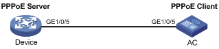
PPPoE client in permanent mode configuration example
Network requirements
As shown in Figure 4, configure the device as a PPPoE server, and configure the AC as a PPPoE client operating in permanent mode.
Configuration procedure
1. Configure the device as the PPPoE server:
# Configure an IP address for interface Virtual-Template 1 and specify an IP address for the peer.
<Device> system-view
[Device] interface virtual-template 1
[Device-Virtual-Template1] ip address 1.1.1.1 255.0.0.0
[Device-Virtual-Template1] remote address 1.1.1.2
[Device-Virtual-Template1] quit
# Enable the PPPoE server on GigabitEthernet 1/0/5, and bind the interface to Virtual-Template 1.
[Device] interface gigabitethernet 1/0/5
[Device-GigabitEthernet1/0/5] pppoe-server bind virtual-template 1
[Device-GigabitEthernet1/0/5] quit
2. Configure the AC as the PPPoE client:
# Create dialer access group 1 and configure a dial access control rule for it.
<AC> system-view
[AC] dialer-group 1 rule ip permit
# Enable bundle DDR on interface Dialer 1.
[AC] interface dialer 1
[AC-Dialer1] dialer bundle enable
# Associate Dialer 1 with dialer access group 1.
[AC-Dialer1] dialer-group 1
[AC-Dialer1] quit
# Configure Dialer 1 to obtain an IP address through PPP negotiation.
[AC-Dialer1] ip address ppp-negotiate
[AC-Dialer1] quit
# Configure a PPPoE session that corresponds to dialer bundle 1 (dialer bundle 1 corresponds to interface Dialer 1).
[AC] interface gigabitethernet 1/0/5
[AC-GigabitEthernet1/0/5] pppoe-client dial-bundle-number 1
[AC-GigabitEthernet1/0/5] quit
# Configure the PPPoE session to operate in permanent mode.
[AC] interface dialer 1
[AC-Dialer1] dialer timer idle 0
# Set the DDR auto-dial interval to 60 seconds.
[AC-Dialer1] dialer timer autodial 60
[AC-Dialer1] quit
# Configure a static route.
[AC] ip route-static 1.1.1.1 255.0.0.0 dialer 1
Verifying the configuration
# Display summary information about the PPPoE session established between the AC and the device (PPPoE server).
[AC-Dialer1] display pppoe-client session summary
Bundle ID Interface VA RemoteMAC LocalMAC State
1 1 GE1/0/5 VA0 00e0-1400-4300 00e0-1500-4100 SESSION
PPPoE client in on-demand mode configuration example
Network requirements
As shown in Figure 5, perform the following tasks:
· Configure the device as a PPPoE server.
· Configure the AC as a PPPoE client operating in on-demand mode, and set the link idle-timeout timer to 150 seconds.
Configuration procedure
1. Configure the device as the PPPoE server:
# Configure an IP address for interface Virtual-Template 1 and specify an IP address for the peer.
<Device> system-view
[Device] interface virtual-template 1
[Device-Virtual-Template1] ip address 1.1.1.1 255.0.0.0
[Device-Virtual-Template1] remote address 1.1.1.2
[Device-Virtual-Template1] quit
# Enable the PPPoE server on GigabitEthernet 1/0/5, and bind the interface to Virtual-Template 1.
[Device] interface gigabitethernet 1/0/5
[Device-GigabitEthernet1/0/5] pppoe-server bind virtual-template 1
[Device-GigabitEthernet1/0/5] quit
2. Configure the AC as the PPPoE client.
# Create dialer access group 1 and configure a dial access control rule for it.
<AC> system-view
[AC] dialer-group 1 rule ip permit
# Enable bundle DDR on interface Dialer 1.
[AC] interface dialer 1
[AC-Dialer1] dialer bundle enable
# Associate Dialer 1 with dialer access group 1.
[AC-Dialer1] dialer-group 1
# Configure Dialer 1 to obtain an IP address through PPP negotiation.
[AC-Dialer1] ip address ppp-negotiate
[AC-Dialer1] quit
# Configure a PPPoE session that corresponds to dialer bundle 1 (dialer bundle 1 corresponds to Dialer 1).
[AC] interface gigabitethernet 1/0/5
[AC-GigabitEthernet1/0/5] pppoe-client dial-bundle-number 1
[AC-GigabitEthernet1/0/5] quit
# Configure a static route.
[AC] ip route-static 1.1.1.1 255.0.0.0 dialer 1
# Set the link-idle timeout timer to 150 seconds.
[AC] interface dialer 1
[AC-Dialer1] dialer timer idle 150
[AC-Dialer1] quit
Verifying the configuration
# Display summary information about the PPPoE session established between the AC and the device (PPPoE server).
[AC-Dialer1] display pppoe-client session summary
Bundle ID Interface VA RemoteMAC LocalMAC State
1 1 GE1/0/5 VA0 00e0-1400-4300 00e0-1500-4100 SESSION
PPPoE client in diagnostic mode configuration example
Network requirements
As shown in Figure 6, perform the following tasks:
· Configure the device as a PPPoE server.
· Configure the AC as a PPPoE client operating in diagnostic mode, and set the diagnostic interval to 200 seconds.

Configuration procedure
1. Configure the device as the PPPoE server:
# Configure an IP address for interface Virtual-Template 1 and specify an IP address for the peer.
<Device> system-view
[Device] interface virtual-template 1
[Device-Virtual-Template1] ip address 1.1.1.1 255.0.0.0
[Device-Virtual-Template1] remote address 1.1.1.2
[Device-Virtual-Template1] quit
# Enable the PPPoE server on GigabitEthernet 1/0/5, and bind the interface to Virtual-Template 1.
[Device] interface gigabitethernet 1/0/5
[Device-GigabitEthernet1/0/5] pppoe-server bind virtual-template 1
[Device-GigabitEthernet1/0/5] quit
2. Configure the AC as the PPPoE client.
# Create dialer access group 1 and configure a dial access control rule for it.
<AC> system-view
[AC] dialer-group 1 rule ip permit
# Enable bundle DDR on interface Dialer 1.
[AC] interface dialer 1
[AC-Dialer1] dialer bundle enable
# Associate Dialer 1 with dialer access group 1.
[AC-Dialer1] dialer-group 1
# Configure Dialer 1 to obtain an IP address through PPP negotiation.
[AC-Dialer1] ip address ppp-negotiate
[AC-Dialer1] quit
# Configure a PPPoE session that corresponds to dialer bundle 1 (dialer bundle 1 corresponds to Dialer 1).
[AC] interface gigabitethernet 1/0/5
[AC-GigabitEthernet1/0/5] pppoe-client dial-bundle-number 1
[AC-GigabitEthernet1/0/5] quit
# Configure the PPPoE session to operate in diagnostic mode, and set the diagnostic interval to 200 seconds.
[AC] interface dialer 1
[AC-Dialer1] dialer diagnose interval 200
# Set the DDR auto-dial interval to 10 seconds.
[AC-Dialer1] dialer timer autodial 10
Verifying the configuration
# Display summary information about the PPPoE session established between the AC and the device (PPPoE server).
[AC-Dialer1] display pppoe-client session summary
Bundle ID Interface VA RemoteMAC LocalMAC State
1 1 GE1/0/5 VA0 00e0-1400-4300 00e0-1500-4100 SESSION
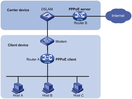
Configuration example for connecting a LAN to the Internet through an ADSL modem
Network requirements
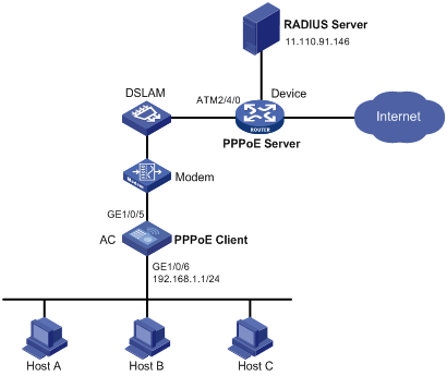
As shown in Figure 7, configure PPPoE to meet the following requirements:
· The AC provides Internet access for Host A, Host B, and Host C. It connects to the DSLAM through an ADSL modem and a permanent PPPoE session.
· The username and password of the ADSL account are user1 and 123456.
· The AC acts as a PPPoE client, and it allows the hosts in the LAN to access the Internet without PPPoE client software.
· The device acts as the PPPoE server. It performs RADIUS authentication, authorization, and accounting.
Configuration procedure
1. Configure the AC as a PPPoE client:
# Create dialer access group 1 and configure a dial access control rule for it.
<AC> system-view
[AC] dialer-group 1 rule ip permit
# Enable bundle DDR on interface Dialer 1.
[AC] interface dialer 1
[AC-Dialer1] dialer bundle enable
# Associate Dialer 1 with dialer access group 1.
[AC-Dialer1] dialer-group 1
# Configure Dialer 1 to obtain an IP address through PPP negotiation.
[AC-Dialer1] ip address ppp-negotiate
# Configure the PPPoE session to operate in permanent mode.
[AC-Dialer1] dialer timer idle 0
# Configure the PAP username and password.
[AC-Dialer1] ppp pap local-user user1 password simple 123456
[AC-Dialer1] quit
# Configure a PPPoE session.
[AC] interface gigabitethernet 1/0/5
[AC-GigabitEthernet1/0/5] pppoe-client dial-bundle-number 1
[AC-GigabitEthernet1/0/5] quit
# Configure an IP address for the LAN interface.
[AC] interface gigabitethernet 1/0/6
[AC-GigabitEthernet1/0/6] ip address 192.168.1.1 255.255.255.0
[AC-GigabitEthernet1/0/6] quit
# Configure a default route.
[AC] ip route-static 0.0.0.0 0 dialer 1
If the hosts in the LAN use private addresses, configure NAT on AC.
2. Configure the device as the PPPoE server:
# Configure virtual template 1 to use PAP for authentication and use a PPP address pool to assign IP addresses.
<Device> system-view
[Device] interface virtual-template 1
[Device-Virtual-Template1] ppp authentication-mode pap domain system
[Device-Virtual-Template1] remote address pool 1
[Device-Virtual-Template1] ip address 1.1.1.1 255.0.0.0
[Device-Virtual-Template1] quit
# Configure a local PPP address pool that contains nine assignable IP addresses.
[Device] ip pool 1 1.1.1.2 1.1.1.10
# Enable the PPPoE server on the virtual Ethernet interface.
[Device] interface virtual-ethernet 1
[Device-Virtual-Ethernet1] mac-address 0001-0000-0001
[Device-Virtual-Ethernet1] pppoe-server bind virtual-template 1
[Device-Virtual-Ethernet1] quit
# Configure an ATM interface.
[Device] interface atm 2/4/0.1
[Device-ATM2/4/0.1] pvc to_adsl_a 0/60
[Device-ATM2/4/0.1-pvc-to_adsl_a-0/60] map bridge virtual-ethernet 1
[Device-ATM2/4/0.1-pvc-to_adsl_a-0/60] quit
[Device-ATM2/4/0.1] quit
# Configure the default ISP domain system to use the RADIUS scheme for authentication, authorization, and accounting.
[Device] domain system
[Device-isp-system] authentication ppp radius-scheme cams
[Device-isp-system] authorization ppp radius-scheme cams
[Device-isp-system] accounting ppp radius-scheme cams
[Device-isp-system] quit
# Configure a RADIUS scheme, and assign an IP address and port number for the RADIUS server.
[Device] radius scheme cams
[Device-radius-cams] primary authentication 11.110.91.146 1812
[Device-radius-cams] primary accounting 11.110.91.146 1813
# Set the shared keys for secure communication with the RADIUS server to expert in plain text.
[Device-radius-cams] key authentication simple expert
[Device-radius-cams] key accounting simple expert
[Device-radius-cams] quit
3. Configure the RADIUS server:
# Configure the authentication and accounting passwords as expert.
# Add a PPPoE user with username user1 and password 123456.
For more information about RADIUS, see Security Configuration Guide.
Verifying the configuration
# Display summary information for the PPPoE session between the AC and the device.
[AC] display pppoe-client session summary
Bundle ID Interface VA RemoteMAC LocalMAC State
1 1 GE1/0/5 VA0 0001-0000-0001 00e0-1500-4100 SESSION
Host A, Host B, and Host C can thus access the Internet. For example, they can browse a web page through IE.
Configuring L2TP
The device can only operate as an LNS.
The following matrix shows the feature and hardware compatibility:
|
Hardware series |
Model |
L2TP compatibility |
|
WX1800H series |
WX1804H WX1810H WX1820H |
Yes |
|
WX1840H |
No |
|
|
WX3800H series |
WX3820H WX3840H |
No |
|
WX5800H series |
WX5860H |
No |
Overview
The Layer 2 Tunneling Protocol (L2TP) is a Virtual Private Dialup Network (VPDN) tunneling protocol. L2TP sets up point-to-point tunnels across a public network (for example, the Internet) and transmits encapsulated PPP frames (L2TP packets) over the tunnels. With L2TP, remote users can access the private networks through L2TP tunnels after connecting to a public network by using PPP.
As a Layer 2 VPN technology, L2TP provides a secure, cost-effective solution for remote users to access private networks.
Typical L2TP networking
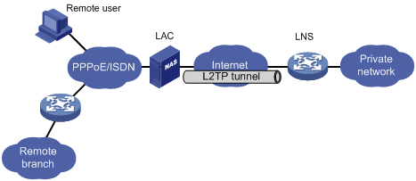
As shown in Figure 8, a typical L2TP network has the following components:
· Remote system—A remote system is usually a remote user's host or a remote branch's device that needs to access the private network.
· LAC—An L2TP access concentrator (LAC) is both PPP and L2TP capable. It is usually a network access server (NAS) located at a local ISP, which provides access services mainly for PPP users.
An LAC is an endpoint of an L2TP tunnel and lies between an LNS and a remote system. It encapsulates packets received from a remote system by using L2TP and then sends the encapsulated packets to the LNS. It decapsulates packets received from the LNS and then sends the decapsulated packets to the intended remote system.
· LNS—An L2TP network server (LNS) is both PPP and L2TP capable. It is usually an edge device on an enterprise network.
An LNS is the other endpoint of an L2TP tunnel. It is the logical termination point of a PPP session tunneled by the LAC. L2TP extends the termination point of a PPP session from a NAS to an LNS by establishing a tunnel.
L2TP message types and encapsulation structure
L2TP uses the following types of messages:
· Control messages—Used to establish, maintain, and delete L2TP tunnels and sessions. Control messages are transmitted over a reliable control channel, which supports flow control and congestion control.
· Data messages—Used to encapsulate PPP frames, as shown in Figure 9. Data messages are transmitted over an unreliable data channel and are not retransmitted when packet loss occurs. Data messages can use sequence numbers to reorder packets that are disordered during transport.
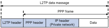
As shown in Figure 10, both control messages and data messages are encapsulated in UDP datagrams.
Figure 10 L2TP encapsulation structure
![]()
L2TP tunnel and session
An L2TP tunnel is a virtual point-to-point connection between an LAC and an LNS. Multiple L2TP tunnels can be established between an LNS and an LAC. An L2TP tunnel can carry one or more L2TP sessions. Each L2TP session corresponds to a PPP session and is multiplexed on an L2TP tunnel. An L2TP session is established between the LAC and LNS when an end-to-end PPP session is established between a remote system and the LNS. Data frames for the PPP session are transmitted over the tunnel between the LAC and LNS.
L2TP tunneling modes and tunnel establishment process
L2TP tunneling modes include NAS-initiated and client-initiated.
NAS-initiated tunneling mode
As shown in Figure 11, a remote system dials in to the LAC through a PPPoE/ISDN network. The LAC initiates a tunneling request to the LNS over the Internet.
Figure 11 NAS-initiated tunneling mode
A NAS-initiated tunnel has the following characteristics:
· The remote system only needs to support PPP, and it does not need to support L2TP.
· Authentication and accounting of the remote system can be implemented on the LAC or LNS.
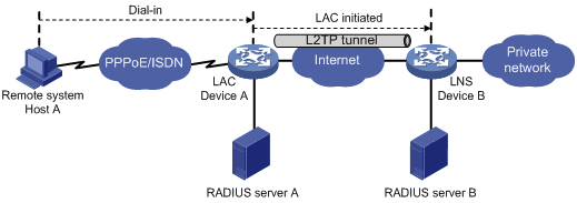
Figure 12 NAS-initiated tunnel establishment process
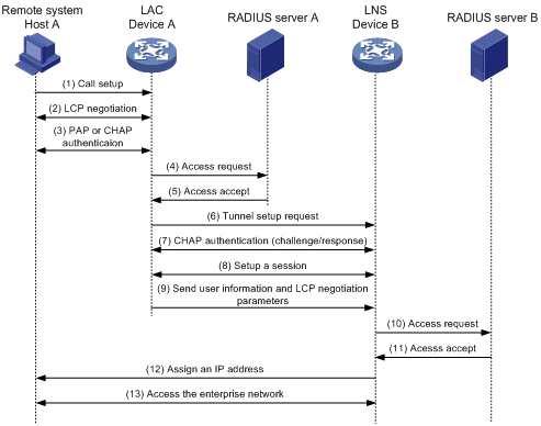
As shown in Figure 12, the following workflow is used to establish a NAS-initiated tunnel:
1. A remote system (Host A) initiates a PPP connection to the LAC (Device A).
2. The remote system and LAC perform PPP LCP negotiation.
3. The LAC authenticates PPP user information of Host A by using PAP or CHAP.
4. The LAC sends the authentication information (username and password) to its RADIUS server (RADIUS server A) for authentication.
5. RADIUS server A authenticates the user and returns the result.
6. The LAC initiates an L2TP tunneling request to the LNS (Device B) when the following conditions exist:
? The user passes the authentication.
? The user is determined to be an L2TP user according to the username or the ISP domain to which the user belongs.
7. If tunnel authentication is needed, the LAC and LNS send CHAP challenge messages to authenticate each other before successfully establishing an L2TP tunnel.
8. The LAC and LNS negotiate to establish L2TP sessions.
9. The LAC sends PPP user information and PPP negotiation parameters to the LNS.
10. The LNS sends the authentication information to its RADIUS server (RADIUS server B) for authentication.
11. RADIUS server B authenticates the user and returns the result.
12. If the user passes the authentication, the LNS assigns a private IP address to the remote system (Host A).
13. The PPP user can access internal resources of the enterprise.
In steps 12 and 13, the LAC forwards packets for the remote system and LNS. Host A and LAC exchange PPP frames, and the LAC and LNS exchange L2TP packets.
Client-initiated tunneling mode
As shown in Figure 13, a remote system running L2TP (LAC client) has a public IP address to communicate with the LNS through the Internet. The LAC client can directly initiate a tunneling request to the LNS without any dedicated LAC devices.
Figure 13 Client-initiated tunneling mode
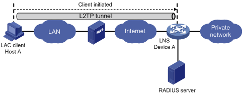
A client-initiated tunnel has the following characteristics:
· A client-initiated tunnel has higher security because it is established between a remote system and the LNS.
· The remote system must support L2TP and be able to communicate with the LNS. This causes poor expandability.
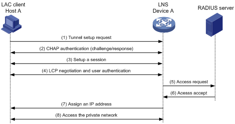
As shown in Figure 14, the workflow for establishing a client-initiated tunnel is similar to that for establishing a NAS-initiated tunnel. (Details not shown.)
Figure 14 Client-initiated tunnel establishment process
L2TP features
· Flexible identity authentication mechanism and high security—L2TP by itself does not provide security for connections. However, it has all the security features of PPP and allows for PPP authentication (CHAP or PAP). L2TP can also cooperate with IPsec to improve security for tunneled data.
· Multiprotocol transmission—L2TP tunnels PPP frames, which can be used to encapsulate packets of multiple network layer protocols.
· RADIUS authentication—An LAC or LNS can send the username and password of a remote user to a RADIUS server for authentication.
· Private address allocation—An LNS can dynamically allocate private addresses to remote users. This facilitates address allocation for private internets (RFC 1918) and improves security.
· Flexible accounting—Accounting can be simultaneously performed on the LAC and LNS. This allows bills to be generated on the ISP side and charging and auditing to be processed on the enterprise gateway. L2TP can provide accounting data, including inbound and outbound traffic statistics (in packets and bytes) and the connection's start time and end time. The AAA server uses these data for flexible accounting.
· Reliability—L2TP supports LNS backup. When the connection to the primary LNS is torn down, an LAC can establish a new connection to a secondary LNS. This redundancy enhances the reliability of L2TP services.
· Issuing tunnel attributes by RADIUS server to LAC—In NAS-initiated mode, the tunnel attributes can be issued by the RADIUS server to the LAC. For the LAC to receive these attributes, enable L2TP and configure remote AAA authentication for PPP users on the LAC.
When an L2TP user dials in to the LAC, the LAC as the RADIUS client sends the user information to the RADIUS server. The RADIUS server authenticates the PPP user, returns the result to the LAC, and issues L2TP tunnel attributes for the PPP user to the LAC. The LAC then sets up an L2TP tunnel and sessions based on the issued L2TP tunnel attributes.
Table 2 Tunnel attributes that can be issued by the RADIUS server
|
Attribute number |
Attribute name |
Description |
|
64 |
Tunnel-Type |
Tunnel type, which can only be L2TP. |
|
65 |
Tunnel-Medium-Type |
Transmission medium type for the tunnel, which can only be IPv4. |
|
67 |
Tunnel-Server-Endpoint |
IP address of the LNS. |
|
69 |
Tunnel-Password |
Key used to authenticate a peer of the tunnel. |
|
81 |
Tunnel-Private-Group-ID |
Group ID for the tunnel. The LAC sends this value to the LNS for the LNS to perform an operation accordingly. |
|
82 |
Tunnel-Assignment-ID |
Assignment ID for the tunnel. It is used to indicate the tunnel to which a session is assigned. L2TP users with the same Tunnel-Assignment-ID, Tunnel-Server-Endpoint, and Tunnel-Password attributes share an L2TP tunnel. |
|
90 |
Tunnel-Client-Auth-ID |
Tunnel name. It is used to indicate the local tunnel. |
The RADIUS server can issue only one set of the L2TP tunnel attributes in a RADIUS packet.
The RADIUS-issued tunnel attributes override the tunnel attributes manually configured on the LAC, but not vice versa.
· L2TP tunnel switching—Also called multihop L2TP tunneling. As shown in Figure 15, the Layer 2 tunnel switch (LTS) terminates L2TP packets from each LAC as an LNS. It then sends these packets to a destination LNS as an LAC.
L2TP tunnel switching has the following features:
? Simplified configuration and deployment—When LACs and LNSs are in different management domains:
- All LACs consider the LTS as an LNS and do not need to differentiate LNSs on the network.
- All LNSs consider the LTS as an LAC and are not affected by the addition or deletion of LACs.
? L2TP tunnel sharing—Different users can share the same L2TP tunnel between the LAC and the LTS. The LTS distributes data of different users to different LNSs.
Figure 15 L2TP tunnel switching network diagram
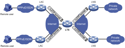
Protocols and standards
· RFC 1661, The Point-to-Point Protocol (PPP)
· RFC 1918, Address Allocation for Private Internets
· RFC 2661, Layer Two Tunneling Protocol "L2TP"
· RFC 2868, RADIUS Attributes for Tunnel Protocol Support
L2TP configuration task list
When you configure L2TP, perform the following tasks:
1. Determine the network devices needed according to the networking environment.
? For NAS-initiated mode, configure both the LAC and the LNS.
? For client-initiated mode, you only need to configure the LNS.
2. Configure the devices based on the intended role (LAC or LNS) on the network.
To configure a device as an LNS in NAS-initiated and client-initiated mode, complete the following tasks:
|
Tasks at a glance |
|
(Required.) Configuring basic L2TP capabilities |
|
· (Required.) Creating a VT interface · (Optional.) Configuring a VA pool · (Required.) Configuring an LNS to accept L2TP tunneling requests from an LAC · (Optional.) Configuring user authentication on an LNS · (Optional.) Configuring AAA authentication on an LNS |
|
(Optional.) Configuring optional L2TP parameters: · Configuring L2TP tunnel authentication · Enabling session flow control · Setting the DSCP value of L2TP packets |
Configuring basic L2TP capabilities
Basic L2TP capability configuration includes the following tasks:
· Enabling L2TP—L2TP must be enabled for L2TP configurations to take effect.
· Creating an L2TP group—An L2TP group is intended to represent a group of parameters. This enables not only flexible L2TP configuration on devices, but also one-to-one and one-to-many networking applications for LACs and LNSs. An L2TP group has local significance only. However, the relevant settings of the L2TP groups on the LAC and LNS must match. For example, the local tunnel name configured on the LAC must match the tunnel peer name configured on the LNS.
· Configuring the local tunnel name—The local tunnel name identifies the tunnel at the local end during tunnel negotiation between an LAC and an LNS.
To configure basic L2TP capabilities:
|
Step |
Command |
Remarks |
|
1. Enter system view. |
system-view |
N/A |
|
2. Enable L2TP. |
l2tp enable |
By default, L2TP is disabled. |
|
3. Create an L2TP group, specify its mode, and enter its view. |
l2tp-group group-number mode lns |
By default, no L2TP group exists. |
|
4. Specify the local tunnel name. |
tunnel name name |
Optional. By default, the device name is used. |
Configuring an LNS
An LNS responds to the tunneling requests from an LAC, authenticates users, and assigns IP addresses to users.
Creating a VT interface
After an L2TP session is established, a virtual access (VA) interface is needed for data exchange with the peer. The system will dynamically create VA interfaces based on the parameters of the virtual template (VT) interface. To configure an LNS, first create a VT interface and configure the following parameters for it:
· Interface IP address.
· Authentication mode for PPP users.
· IP addresses allocated by the LNS to PPP users.
For information about configuring VT interfaces, see "Configuring PPP" and Layer 3—IP Services Configuration Guide.
Configuring a VA pool
A VA pool contains a group of VA interfaces. You can configure a VA pool to improve the performance of establishing or terminating L2TP connections. The LNS selects a VA interface from the pool for a requesting user and releases the VA interface when the user goes offline. When a VA pool is exhausted, the system creates a VA interface for an L2TP connection and deletes it when the user goes offline.
Configuration guidelines
When you configure a VA pool, follow these guidelines:
· A VT interface can be associated with only one VA pool. To change the capacity of a VA pool, delete the previous configuration and reconfigure the VA pool.
· Creating or deleting a VA pool takes time. During the process of creating or deleting a VA pool, users can come online or go offline, but the VA pool does not take effect.
· The system might create a VA pool that contains VA interfaces less than the specified number because of insufficient resources. To view the number of available VA interfaces and the current state of the VA pool, use the display l2tp va-pool command.
· Create a VA pool with an appropriate capacity, because a VA pool occupies much system memory.
· Deleting a VA pool does not log off the users who are using VA interfaces in the VA pool.
Configuration procedure
To configure a VA pool:
|
Step |
Command |
Remarks |
|
1. Enter system view. |
system-view |
N/A |
|
2. Create a VA pool. |
l2tp virtual-template template-number va-pool va-volume |
By default, no VA pool exists. |
Configuring an LNS to accept L2TP tunneling requests from an LAC
When receiving a tunneling request, an LNS performs the following operations:
· Determines whether to accept the tunneling request by checking whether the name of the tunnel peer (LAC) matches the one configured.
· Determines the VT interface to be used for creating the VA interface.
To configure an LNS to accept L2TP tunneling requests from an LAC:
|
Step |
Command |
Remarks |
|
|
1. Enter system view. |
system-view |
N/A |
|
|
2. Enter L2TP group view in LNS mode. |
l2tp-group group-number [ mode lns ] |
N/A |
|
|
3. Configure the LNS to accept tunneling requests from an LAC and specify the VT interface to be used for tunnel setup. |
· If the L2TP group number is 1: · If the L2TP group number is not 1: |
By default, an LNS denies tunneling requests from any LAC. If the L2TP group number is 1, the remote remote-name option is optional. If you do not specify this option, the LNS accepts tunneling requests from any LAC. |
|
Configuring user authentication on an LNS
An LNS can be configured to authenticate a user that has passed authentication on the LAC to increase security. In this case, the user is authenticated once on the LAC and once on the LNS. An L2TP tunnel can be established only when both authentications succeed.
An LNS provides the following authentication methods in ascending order of priority:
· Proxy authentication—The LNS uses the LAC as an authentication proxy. The LAC sends the LNS all user authentication information from users and the authentication method configured on the LAC itself. The LNS then checks the user validity according to the received information and the locally configured authentication method.
· Mandatory CHAP authentication—The LNS uses CHAP authentication to reauthenticate users who have passed authentication on the LAC.
· LCP renegotiation—The LNS ignores the LAC proxy authentication information and performs a new round of LCP negotiation with the user.
The LNS chooses an authentication method depending on your configuration.
· If you configure both LCP renegotiation and mandatory CHAP authentication, the LNS uses LCP renegotiation.
· If you configure only mandatory CHAP authentication, the LNS performs CHAP authentication for users after proxy authentication succeeds.
· If you configure neither LCP renegotiation nor mandatory CHAP authentication, the LNS uses the LAC for proxy authentication.
Configuring mandatory CHAP authentication
When mandatory CHAP authentication is configured, a user who uses an LAC to initiate tunneling requests is authenticated by both the LAC and the LNS. Some users might not support the authentication on the LNS. In this situation, do not enable this feature, because CHAP authentication on the LNS will fail.
For this feature to take effect, you must also configure CHAP authentication for the PPP user on the VT interface of the LNS.
To configure mandatory CHAP authentication:
|
Step |
Command |
Remarks |
|
1. Enter system view. |
system-view |
N/A |
|
2. Enter L2TP group view in LNS mode. |
l2tp-group group-number [ mode lns ] |
N/A |
|
3. Configure mandatory CHAP authentication. |
mandatory-chap |
By default, CHAP authentication is not performed on an LNS. This command is effective only on NAS-initiated L2TP tunnels. |
Configuring LCP renegotiation
To establish a NAS-initiated L2TP tunnel, a user first negotiates with the LAC at the start of a PPP session. If the negotiation succeeds, the LAC initiates an L2TP tunneling request and sends user information to the LNS. The LNS then authenticates the user according to the proxy authentication information received.
For the LNS not to accept LCP negotiation parameters, configure this feature to perform a new round of LCP negotiation between the LNS and the user. In this case, the LNS authenticates the user by using the authentication method configured on the corresponding VT interface.
If you enable LCP renegotiation but configure no authentication for the corresponding VT interface, the LNS does not perform an additional authentication for users.
To configure the LNS to perform LCP renegotiation with users:
|
Step |
Command |
Remarks |
|
1. Enter system view. |
system-view |
N/A |
|
2. Enter L2TP group view in LNS mode. |
l2tp-group group-number [ mode lns ] |
N/A |
|
3. Configure the LNS to perform LCP renegotiation with users. |
mandatory-lcp |
By default, an LNS does not perform LCP renegotiation with users. This command is effective only on NAS-initiated L2TP tunnels. |
Configuring AAA authentication on an LNS
After you configure AAA authentication on an LNS, the LNS can authenticate the usernames and passwords of remote access users. If a user passes AAA authentication, the user can communicate with the LNS to access the private network.
Configure AAA authentication on the LNS in one of the following cases:
· LCP renegotiation is not configured in NAS-initiated mode.
· The VT interface is configured with PPP user authentication and LCP renegotiation is configured in NAS-initiated mode.
· The VT interface is configured with PPP user authentication in client-initiated mode.
Configuring optional L2TP parameters
The optional L2TP parameter configuration tasks apply to both LACs and LNSs.
Configuring L2TP tunnel authentication
Tunnel authentication allows the LAC and LNS to authenticate each other. Either the LAC or the LNS can initiate a tunnel authentication request.
You can enable tunnel authentication on both sides or either side.
To ensure a successful tunnel establishment when tunnel authentication is enabled on both sides or either side, set the same non-null key on the LAC and the LNS. To set the tunnel authentication key, use the tunnel password command.
When neither side is enabled with tunnel authentication, the key settings of the LAC and the LNS do not affect the tunnel establishment.
To ensure tunnel security, enable tunnel authentication.
For the tunnel authentication key change to take effect, change the tunnel authentication key before tunnel negotiation is performed.
To configure L2TP tunnel authentication:
|
Step |
Command |
Remarks |
|
1. Enter system view. |
system-view |
N/A |
|
2. Enter L2TP group view. |
l2tp-group group-number [ mode lns ] |
N/A |
|
3. Enable L2TP tunnel authentication. |
tunnel authentication |
By default, L2TP tunnel authentication is enabled. |
|
4. Set the tunnel authentication key. |
tunnel password { cipher | simple } password |
By default, no key is set. |
Setting the Hello interval
To check the connectivity of a tunnel, the LAC and LNS periodically send each other Hello packets. At receipt of a Hello packet, the LAC or LNS returns a response packet. If the LAC or LNS receives no response packets from the peer within the Hello interval, it retransmits the Hello packet. If it receives no response packets from the peer after transmitting the Hello packet five times, it considers the L2TP tunnel to be down.
To set the Hello interval:
|
Step |
Command |
Remarks |
|
1. Enter system view. |
system-view |
N/A |
|
2. Enter L2TP group view. |
l2tp-group group-number [ mode lns ] |
N/A |
|
3. Set the Hello interval. |
tunnel timer hello hello-interval |
The default setting is 60 seconds. |
Enabling session flow control
This feature adds sequence numbers to transmitted packets and uses them to reorder packets arriving out of order and to detect lost packets.
This feature takes effect on both sent and received L2TP data messages. The L2TP sessions support this feature if either the LAC or LNS is enabled with this feature.
To enable session flow control:
|
Step |
Command |
Remarks |
|
1. Enter system view. |
system-view |
N/A |
|
2. Enter L2TP group view. |
l2tp-group group-number [ mode lns ] |
N/A |
|
3. Enable the session flow control feature. |
tunnel flow-control |
By default, this feature is disabled. |
Setting the DSCP value of L2TP packets
The DSCP field is the first 6 bits of the IP ToS byte. This field marks the priority of IP packets for forwarding. This feature sets the DSCP value for the IP packet when L2TP encapsulates a PPP frame into an IP packet.
To set the DSCP value of L2TP packets:
|
Step |
Command |
Remarks |
|
1. Enter system view. |
system-view |
N/A |
|
2. Enter L2TP group view. |
l2tp-group group-number [ mode lns ] |
N/A |
|
ip dscp dscp-value |
The default setting is 0. |
Assigning a tunnel peer to a VPN
By default, the device transmits L2TP control messages and data messages over the public network. With this feature, the device transmits them in a VPN by searching the routing table in the VPN.
When one L2TP endpoint is in a VPN, assign the peer endpoint to the VPN for correct packet forwarding between the two endpoints.
To assign the tunnel peer to a VPN:
|
Step |
Command |
Remarks |
|
1. Enter system view. |
system-view |
N/A |
|
2. Enter L2TP group view. |
l2tp-group group-number [ mode lns ] |
N/A |
|
3. Assign the tunnel peer to a VPN. |
vpn-instance vpn-instance-name |
By default, a tunnel peer belongs to the public network. The tunnel peer and the physical port connecting to the tunnel peer should belong to the same VPN. The VPN to which this physical port belongs is configured by using the ip binding vpn-instance command. |
Setting the TSA ID of the LTS
To detect loops, the LTS compares the configured TSA ID with each TSA ID AVP in a received ICRQ packet.
· If a match is found, a loop exists. The LTS immediately tears down the session.
· If no match is found, the LTS performs the following operations:
? Encapsulates the configured TSA ID into a new TSA ID AVP.
? Appends it to the packet.
? Sends the packet to the next hop LTS.
To avoid loop detection errors, make sure the TSA ID of each LTS is unique.
To set the TSA ID of the LTS:
|
Step |
Command |
Remarks |
|
1. Enter system view. |
system-view |
N/A |
|
2. Set the TSA ID of the LTS and enable L2TP loop detection on the LTS. |
l2tp tsa-id tsa-id |
By default, the TSA ID of the LTS is not configured, and L2TP loop detection is disabled on the LTS. |
Displaying and maintaining L2TP
Execute display commands in any view and reset commands in user view.
|
Task |
Command |
|
Display L2TP tunnel information. |
display l2tp tunnel [ statistics ] |
|
Display temporary L2TP session information. |
display l2tp session temporary |
|
Display L2TP session information. |
display l2tp session [ statistics ] |
|
Display information about L2TP VA pools. |
display l2tp va-pool |
|
Disconnect an L2TP tunnel. |
reset l2tp tunnel { id tunnel-id | name remote-name } |
L2TP configuration examples
Configuration example for NAS-initiated L2TP tunnel
Network requirements
As shown in Figure 16, a PPP user is connected to an LNS through an LAC.
Set up an L2TP tunnel between the LAC and LNS to allow the PPP user to access the corporate network.

Configuration procedure
1. Configure the LNS:
# Configure IP addresses for the interfaces. (Details not shown.)
# Create a local user named vpdnuser, set the password, and enable the PPP service.
<LNS> system-view
[LNS] local-user vpdnuser class network
[LNS-luser-network-vpdnuser] password simple Hello
[LNS-luser-network-vpdnuser] service-type ppp
[LNS-luser-network-vpdnuser] quit
# Configure local authentication for PPP users in ISP domain system.
[LNS] domain system
[LNS-isp-system] authentication ppp local
[LNS-isp-system] quit
# Enable L2TP.
[LNS] l2tp enable
# Create a PPP address pool.
[LNS] ip pool aaa 192.168.0.10 192.168.0.20
[LNS] ip pool aaa gateway 192.168.0.1
# Create interface Virtual-Template 1, specify its PPP authentication mode as CHAP, and use the address pool aaa to assign IP addresses to the PPP users.
[LNS] interface virtual-template 1
[LNS-virtual-template1] ppp authentication-mode chap domain system
[LNS-virtual-template1] remote address pool aaa
[LNS-virtual-template1] quit
# Create L2TP group 1 in LNS mode.
[LNS] l2tp-group 1 mode lns
# Configure the local tunnel name as LNS.
[LNS-l2tp1] tunnel name LNS
# Specify Virtual-Template 1 for receiving calls from an LAC.
[LNS-l2tp1] allow l2tp virtual-template 1 remote LAC
# Enable tunnel authentication, and specify the tunnel authentication key as aabbcc.
[LNS-l2tp1] tunnel authentication
[LNS-l2tp1] tunnel password simple aabbcc
[LNS-l2tp1] quit
2. On the remote system, enter vpdnuser as the username and Hello as the password in the dial-up network window to dial a connection.
Verifying the configuration
After the dial-up connection is established, the remote system can obtain an IP address and can ping the private IP address of the LNS.
# On the LNS, use the display l2tp tunnel command to check the established L2TP tunnels.
[LNS] display l2tp tunnel
LocalTID RemoteTID State Sessions RemoteAddress RemotePort RemoteName
196 3542 Established 1 1.1.2.1 1701 LAC
# On the LNS, use the display l2tp session command to check the established L2TP sessions.
[LNS] display l2tp session
LocalSID RemoteSID LocalTID State
2041 64 196 Established
Configuration example for client-initiated L2TP tunnel
Network requirements
As shown in Figure 17, a PPP user directly initiates a tunneling request to the LNS to access the corporate network.
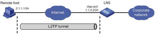
Configuration procedure
1. Configure the LNS:
# Configure IP addresses for the interfaces. (Details not shown.)
# Configure the route between the LNS and the remote host. (Details not shown.)
# Create a local user named vpdnuser, set the password, and enable the PPP service.
[LNS] local-user vpdnuser class network
[LNS-luser-network-vpdnuser] password simple Hello
[LNS-luser-network-vpdnuser] service-type ppp
[LNS-luser-network-vpdnuser] quit
# Configure local authentication for PPP users in ISP domain system.
[LNS] domain system
[LNS-isp-system] authentication ppp local
[LNS-isp-system] quit
# Enable L2TP.
[LNS] l2tp enable
# Create a PPP address pool.
[LNS] ip pool aaa 192.168.0.10 192.168.0.20
[LNS] ip pool aaa gateway 192.168.0.1
# Create interface Virtual-Template 1, specify its PPP authentication mode as CHAP, and use address pool aaa to assign IP addresses to the PPP users.
[LNS] interface virtual-template 1
[LNS-virtual-template1] ppp authentication-mode chap domain system
[LNS-virtual-template1] remote address pool aaa
[LNS-virtual-template1] quit
# Create L2TP group 1 in LNS mode.
[LNS] l2tp-group 1 mode lns
# Configure the local tunnel name as LNS.
[LNS-l2tp1] tunnel name LNS
# Specify Virtual-Template 1 for receiving calls.
[LNS-l2tp1] allow l2tp virtual-template 1
# Disable tunnel authentication.
[LNS-l2tp1] undo tunnel authentication
2. Configure the remote host:
# Configure the IP address of the remote host as 2.1.1.1, and configure a route to the LNS (1.1.2.2).
# Create a virtual private network connection by using the Windows system, or install the L2TP LAC client software, such as WinVPN Client.
# Complete the following configuration procedure (the procedure depends on the client software):
? Specify the PPP username as vpdnuser and the password as Hello.
? Specify the Internet interface address of the security gateway as the IP address of the LNS. In this example, the Ethernet interface for the tunnel on the LNS has an IP address of 1.1.2.2.
? Modify the connection attributes: set the protocol to L2TP, the encryption attribute to customized, and the authentication mode to CHAP.
Verifying the configuration
# On the remote host, initiate the L2TP connection. After the connection is established, the remote host can obtain the IP address 192.168.0.2 and ping the private IP address of the LNS (192.168.0.1).
# On the LNS, use the display l2tp session command to check the established L2TP session.
[LNS-l2tp1] display l2tp session
LocalSID RemoteSID LocalTID State
89 36245 10878 Established
# On the LNS, use the display l2tp tunnel command to check the established L2TP tunnel.
[LNS-l2tp1] display l2tp tunnel
LocalTID RemoteTID State Sessions RemoteAddress RemotePort RemoteName
10878 21 Established 1 2.1.1.1 1701 PC
Troubleshooting L2TP
Symptom 1: Failure to access the private network
The remote system cannot access the private network.
Analysis and solution
Possible reasons for the access failure include the following:
· Tunnel setup failure, which might occur in the following cases:
? The address of the LNS is set incorrectly on the LAC (see the lns-ip command).
? No L2TP group is configured on the LNS to receive tunneling requests from the tunnel peer (see the allow command).
? Tunnel authentication fails. Tunnel authentication must be enabled on both the LAC and the LNS, and the tunnel authentication keys configured on the two sides must match.
· PPP negotiation failure, which might occur for the following reasons:
? Usernames, passwords, or both are incorrectly configured on the LAC or are not configured on the LNS.
? The LNS cannot allocate addresses. In this case, check whether IP address negotiation settings are correct on the remote system and LNS.
? The authentication type is inconsistent. For example, if the peer does not support MS-CHAP (the default authentication type for a VPN connection created on Windows 2000), the PPP negotiation will fail. In this case, change the authentication type to CHAP on Windows 2000.
Symptom 2: Data transmission failure
Data transmission fails. A connection is established, but data cannot be transmitted. For example, the LAC and LNS cannot ping each other.
Analysis and solution
Possible reasons for the data transmission failure are as follows:
· No route is available. The LAC must have a route to the private network behind the LNS, and vice versa. Otherwise, data transmission fails. You can use the display ip routing-table command on the LAC and LNS to check whether the expected routes are present. If not, configure a static route or a dynamic routing protocol.
· Congestion occurs on the Internet backbone, and the packet loss ratio is high. L2TP data transmission is based on UDP, which does not provide the packet error control feature. If the line is unstable, the LAC and LNS might be unable to ping each other.
A
AAA
L2TP LNS AAA authentication, 41
PPP authentication, 2
PPP CHAP authentication configuration, 5
PPP MS-CHAP authentication configuration, 7
PPP MS-CHAP-V2 authentication configuration, 7
PPP PAP authentication configuration, 4
accounting
PPP accounting enable, 14
PPP RADIUS nas-port-type attribute, 14
assigning
L2TP VPN tunnel peer, 42
authenticating
L2TP LNS AAA authentication, 41
L2TP LNS LCP renegotiation, 40
L2TP LNS mandatory CHAP authentication, 40
L2TP LNS user authentication, 39
L2TP tunnel authentication, 41
PPP authentication, 4
PPP authentication methods, 2
PPP RADIUS nas-port-type attribute, 14
B
blocking
PPPoE blocking tables, 19
C
Challenge Handshake Authentication Protocol. Use CHAP
L2TP LNS mandatory CHAP authentication, 40
L2TP LNS mandatory CHAP user authentication, 39
PPP authentication, 2
PPP configuration, 1, 4
PPPoE configuration, 16, 24
clearing
PPPoE session, 21
client
L2TP tunnel configuration (client-initiated), 45
PPPoE client configuration (diagnostic mode), 27
PPPoE client configuration (on-demand mode), 25
PPPoE client configuration (permanent mode), 24
PPPoE client LAN configuration (ADSL modem), 28
PPPoE session configuration, 23
configuring
L2TP, 31, 37, 44
L2TP basics, 37
L2TP LNS, 38
L2TP LNS AAA authentication, 41
L2TP LNS LAC tunneling request acceptance, 39
L2TP LNS LCP renegotiation, 40
L2TP LNS mandatory CHAP authentication, 40
L2TP LNS user authentication, 39
L2TP optional parameters, 41
L2TP tunnel (client-initiated), 45
L2TP tunnel (NAS-initiated), 44
L2TP tunnel authentication, 41
L2TP VA pool, 38
PPP, 1, 4
PPP authentication, 4
PPP CHAP authentication, 5
PPP DNS server IP address negotiation, 12
PPP IP address negotiation, 9
PPP MS-CHAP authentication, 7
PPP MS-CHAP-V2 authentication, 7
PPP negotiation, 8
PPP negotiation timeout time, 9
PPP PAP authentication, 4
PPP polling, 8
PPPoE, 16, 24
PPPoE access rate limit, 19
PPPoE client, 21
PPPoE client (diagnostic mode), 27
PPPoE client (on-demand mode), 25
PPPoE client (permanent mode), 24
PPPoE client LAN (ADSL modem), 28
PPPoE DDR dialer interface, 22, 22
PPPoE RADIUS NAS-Port-ID attribute, 19
PPPoE server, 17
PPPoE session, 17, 23
PPPoE VA pool, 20
RADIUS nas-port-type attribute, 14
controlling
L2TP control message type, 32
L2TP session flow control, 42, 42
creating
L2TP LNS VT interface, 38
D
data
L2TP data message type, 32
DDR
PPPoE dialer interface configuration, 22, 22
PPPoE session reset, 23
device
PPP authentication configuration, 4
PPP configuration, 1
PPPoE access rate limit, 19
PPPoE client configuration, 21
PPPoE client configuration (diagnostic mode), 27
PPPoE client configuration (on-demand mode), 25
PPPoE client configuration (permanent mode), 24
PPPoE client LAN configuration (ADSL modem), 28
PPPoE configuration, 16, 24
PPPoE DDR dialer interface configuration, 22
PPPoE DDR session reset, 23
PPPoE RADIUS NAS-Port-ID attribute, 19
PPPoE server configuration, 17
PPPoE session clear, 21
PPPoE session configuration, 17, 23
PPPoE session max, 18
DHCP
PPP IPCPv6 negotiation (IPv6), 3
displaying
L2TP, 43
PPP, 15
PPPoE, 23
PPPoE client, 24
PPPoE server, 23
DNS
PPP DNS server IP address negotiation, 12
PPP IPCP negotiation (IPv4), 2
PPP IPCPv6 negotiation (IPv6), 3
PPP negotiation, 8
DSCP
L2TP packet DSCP value, 42
E
enabling
IP segment match, 12
L2TP session flow control, 42
PPP accounting, 14
PPP IP header compression, 13
encapsulating
L2TP encapsulation structure, 32
establishing
L2TP tunnel establishment, 32
Ethernet
PPPoE configuration, 16, 24
F
flow
L2TP session flow control, 42
H
hello
L2TP hello interval, 41
I
ID
L2TP LTS TSA ID setting, 43
Internet
PPPoE configuration, 16, 24
interval
L2TP hello, 41
IP
header compression. Use IPHC
IP address
IP segment match enable, 12
IP addressing
PPP DNS server IP address negotiation, 12
PPP IP address negotiation, 9
PPP negotiation, 8
PPPoE configuration, 16, 24
IP segment match
enable, 12
enable, 13
PPP enable, 13
IPv4
PPP IPCP negotiation, 2
IPv6
PPP IPCPv6 negotiation, 3
K
keepalive
PPP polling, 8
L
access concentrator. Use LAC
basic configuration, 37
configuration, 31, 37, 44
display, 43
encapsulation structure, 32
features, 35
hello interval configuration, 41
LNS AAA authentication, 41
LNS configuration, 38
LNS LAC tunneling request acceptance, 39
LNS LCP renegotiation, 40
LNS mandatory CHAP authentication, 40
LNS user authentication, 39
LNS VT interface creation, 38
LTS TSA ID setting, 43
maintain, 43
message type, 32
network server. Use LNS
networking, 31
optional parameter configuration, 41
packet DSCP value, 42
protocols and standards, 36
session, 32
session flow control configuration, 42
troubleshoot, 46
troubleshoot data transmission failure, 47
troubleshoot remote system network access failure, 46
tunnel, 32
tunnel authentication configuration, 41
tunnel configuration (client-initiated), 45
tunnel configuration (NAS-initiated), 44
tunnel establishment, 32
tunneling mode, 32
tunneling mode (client-initiated), 34
tunneling mode (NAS-initiated), 32
VA pool configuration, 38
VPN tunnel peer assignment, 42
L2TP LNS LAC tunneling request acceptance, 39
L2TP network component, 31
Layer 2
Tunneling protocol. Use L2TP
LCP
L2TP LNS LCP renegotiation, 39, 40
link
PPP configuration, 1, 4
PPP establishment process, 1
PPPoE configuration, 16, 24
AAA authentication, 41
configuration, 38
L2TP network component, 31
LAC tunneling request acceptance, 39
LCP renegotiation, 40
mandatory CHAP authentication, 40
user authentication, 39
VT interface creation, 38
LTS
L2TP LTS TSA ID setting, 43
M
maintaining
L2TP, 43
PPP, 15
PPPoE, 23
PPPoE client, 24
PPPoE server, 23
message
L2TP control type, 32
L2TP data type, 32
mode
L2TP client-initiated tunneling, 34
L2TP NAS-initiated tunneling, 32
monitoring
PPPoE monitoring table, 19
MP
configuration, 1
MS-CHAP
PPP authentication, 2
MS-CHAP-V2
PPP authentication, 2
N
NAS
L2TP NAS-initiated tunneling, 32
L2TP tunnel configuration (NAS-initiated), 44
PPPoE RADIUS NAS-Port-ID attribute, 19
negotiating
PPP DNS server IP address negotiation, 12
PPP IP address negotiation, 9
PPP negotiation, 8
network
L2TP basic configuration, 37
L2TP hello interval, 41
L2TP LNS AAA authentication, 41
L2TP LNS configuration, 38
L2TP LNS LAC tunneling request acceptance, 39
L2TP LNS LCP renegotiation, 40
L2TP LNS mandatory CHAP authentication, 40
L2TP LNS user authentication, 39
L2TP LNS VT interface creation, 38
L2TP LTS TSA ID setting, 43
L2TP networking, 31
L2TP optional parameters, 41
L2TP packet DSCP value, 42
L2TP session flow control, 42
L2TP tunnel authentication, 41
L2TP tunnel configuration (client-initiated), 45
L2TP tunnel configuration (NAS-initiated), 44
L2TP VPN tunnel peer assignment, 42
PPP authentication configuration, 4
PPP authentication methods, 2
PPP IPCP negotiation (IPv4), 2
PPP IPCPv6 negotiation (IPv6), 3
PPP link establishment process, 1
PPPoE client configuration, 21
PPPoE client configuration (diagnostic mode), 27
PPPoE client configuration (on-demand mode), 25
PPPoE client configuration (permanent mode), 24
PPPoE client LAN configuration (ADSL modem), 28
PPPoE server configuration, 17
network management
L2TP configuration, 31, 37, 44
PPP configuration, 1, 4
PPPoE configuration, 16, 24
PPPoE network structure, 16
P
packet
L2TP packet DSCP value, 42
PPP authentication, 2
PPP configuration, 1, 4
PPPoE configuration, 16, 24
parameter
L2TP optional parameters, 41
password
Password Authentication Protocol. Use PAP
peer
L2TP VPN tunnel peer assignment, 42
PPP authentication, 2
PPP CHAP authentication configuration, 5
PPP MS-CHAP authentication configuration, 7
PPP MS-CHAP-V2 authentication configuration, 7
PPP PAP authentication configuration, 4
Point-to-Point Protocol. Use PPP
Point-to-Point Protocol over Ethernet. Use PPPoE
polling
PPP polling, 8
pool
L2TP VA pool configuration, 38
PPPoE VA pool configuration, 20
port
PPPoE RADIUS NAS-Port-ID attribute, 19
accounting enable, 14
authentication configuration, 4
authentication methods, 2
CHAP authentication configuration, 5
configuration, 1, 4
display, 15
IPCP negotiation (IPv4), 2
IPCPv6 negotiation (IPv6), 3
IPHC enable, 13
L2TP configuration, 31, 37, 44
L2TP packet DSCP value, 42
L2TP tunnel configuration (client-initiated), 45
L2TP tunnel configuration (NAS-initiated), 44
link establishment process, 1
maintain, 15
MS-CHAP authentication configuration, 7
MS-CHAP-V2 authentication configuration, 7
negotiation configuration, 8
PAP authentication configuration, 4
polling configuration, 8
PPPoE client configuration (diagnostic mode), 27
PPPoE client configuration (on-demand mode), 25
PPPoE client configuration (permanent mode), 24
PPPoE client LAN configuration (ADSL modem), 28
PPPoE configuration, 16, 24
RADIUS nas-port-type attribute configuration, 14
PPP IPCP
IP segment match enable, 12
access rate limit, 19
client configuration, 21
client configuration (diagnostic mode), 27
client configuration (on-demand mode), 25
client configuration (permanent mode), 24
client display, 24
client LAN configuration (ADSL modem), 28
client maintain, 24
configuration, 24
DDR dialer interface configuration, 22, 22
DDR session reset, 23
display, 23
maintain, 23
network structure, 16
RADIUS NAS-Port-ID attribute configuration, 19
server configuration, 17
server display, 23
server maintain, 23
session clear, 21
session configuration, 17, 23
session max number configuration, 18
VA pool configuration, 20
procedure
assigning L2TP VPN tunnel peer, 42
clearing PPPoE session, 21
configuring L2TP, 37, 44
configuring L2TP basics, 37
configuring L2TP LNS, 38
configuring L2TP LNS AAA authentication, 41
configuring L2TP LNS LAC tunneling request acceptance, 39
configuring L2TP LNS LCP renegotiation, 40
configuring L2TP LNS mandatory CHAP authentication, 40
configuring L2TP LNS user authentication, 39
configuring L2TP optional parameters, 41
configuring L2TP tunnel (client-initiated), 45
configuring L2TP tunnel (NAS-initiated), 44
configuring L2TP tunnel authentication, 41
configuring L2TP VA pool, 38
configuring PPP, 4
configuring PPP authentication, 4
configuring PPP CHAP authentication, 5
configuring PPP DNS server IP address negotiation, 12
configuring PPP IP address negotiation, 9
configuring PPP MS-CHAP authentication, 7
configuring PPP MS-CHAP-V2 authentication, 7
configuring PPP negotiation, 8
configuring PPP negotiation timeout time, 9
configuring PPP PAP authentication, 4
configuring PPP polling, 8
configuring PPPoE, 24
configuring PPPoE access rate limit, 19
configuring PPPoE client, 21
configuring PPPoE client (diagnostic mode), 27
configuring PPPoE client (on-demand mode), 25
configuring PPPoE client (permanent mode), 24
configuring PPPoE client LAN (ADSL modem), 28
configuring PPPoE DDR dialer interface, 22, 22
configuring PPPoE RADIUS NAS-Port-ID attribute, 19
configuring PPPoE server, 17
configuring PPPoE session, 17, 23
configuring PPPoE VA pool, 20
configuring RADIUS nas-port-type attribute, 14
creating L2TP LNS VT interface, 38
displaying L2TP, 43
displaying PPP, 15
displaying PPPoE, 23
displaying PPPoE client, 24
displaying PPPoE server, 23
enabling IP segment match, 12
enabling L2TP session flow control, 42
enabling PPP accounting, 14
enabling PPP IPHC, 13
maintaining L2TP, 43
maintaining PPP, 15
maintaining PPPoE, 23
maintaining PPPoE client, 24
maintaining PPPoE server, 23
resetting PPPoE DDR session, 23
setting L2TP hello interval, 41
setting L2TP LTS TSA ID, 43
setting L2TP packet DSCP value, 42
setting PPPoE session max, 18
troubleshooting L2TP data transmission failure, 47
troubleshooting L2TP remote system network access failure, 46
protocols and standards
L2TP, 36
proxying
L2TP LNS proxy user authentication, 39
R
RADIUS
PPP nas-port-type attribute, 14
PPPoE NAS-Port-ID attribute, 19
remote
L2TP remote system, 31
requesting
L2TP LNS LAC tunneling request acceptance, 39
resetting
PPPoE DDR session, 23
routing
L2TP basic configuration, 37
L2TP configuration, 31, 37, 44
L2TP LNS configuration, 38
L2TP tunnel configuration (client-initiated), 45
L2TP tunnel configuration (NAS-initiated), 44
RTP
PPP IPHC, 13
S
security
PPP authentication, 2
PPP authentication configuration, 4
PPP authentication methods, 2
PPP CHAP authentication configuration, 5
PPP MS-CHAP authentication configuration, 7
PPP MS-CHAP-V2 authentication configuration, 7
PPP PAP authentication configuration, 4
segment
IP segment match enable, 12
server
PPPoE access rate limit, 19
PPPoE session clear, 21
PPPoE session configuration, 17
PPPoE session max, 18
session
L2TP session, 32
L2TP session flow control, 42
PPPoE access rate limit, 19
PPPoE DDR session reset, 23
PPPoE session clear, 21
PPPoE session configuration, 17, 23
PPPoE session max, 18
setting
L2TP hello interval, 41
L2TP LTS TSA ID, 43
L2TP packet DSCP value, 42
PPPoE session max number, 18
T
TCP
PPP IPHC, 13
timeout
PPP negotiation, 8
PPP negotiation timeout time, 9
timer
PPP negotiation timeout time, 9
troubleshooting
L2TP, 46
L2TP data transmission failure, 47
L2TP remote system network access failure, 46
TSA
L2TP LTS TSA ID setting, 43
tunneling
L2TP basic configuration, 37
L2TP client-initiated mode, 34
L2TP configuration, 31, 37, 44
L2TP hello interval, 41
L2TP LNS AAA authentication, 41
L2TP LNS configuration, 38
L2TP LNS LAC tunneling request acceptance, 39
L2TP LNS user authentication, 39
L2TP LNS VT interface creation, 38
L2TP mode, 32
L2TP NAS-initiated mode, 32
L2TP optional parameters, 41
L2TP tunnel, 32
L2TP tunnel authentication, 41
L2TP tunnel configuration (client-initiated), 45
L2TP tunnel configuration (NAS-initiated), 44
L2TP tunnel establishment, 32
L2TP VPN tunnel peer assignment, 42
V
VA interface
pool configuration, 20, 38
virtual
access. See VA
template. See VT
Virtual Private Dialup Network. Use VPDN
L2TP configuration, 31, 37, 44
L2TP tunnel configuration (client-initiated), 45
L2TP tunnel configuration (NAS-initiated), 44
VPN
L2TP configuration, 31, 37, 44
L2TP tunnel configuration (client-initiated), 45
L2TP tunnel configuration (NAS-initiated), 44
L2TP VPN tunnel peer assignment, 42
L2TP VA pool configuration, 38
PPPoE VA pool configuration, 20
VT interface
L2TP LNS VT interface creation, 38
W
WAN access
L2TP configuration, 31, 37, 44
L2TP display, 43
L2TP LNS configuration, 38
L2TP maintain, 43
L2TP optional parameters, 41
L2TP protocols and standards, 36
PPP authentication configuration, 4
PPP configuration, 1, 4
PPP display, 15
PPP IPCP negotiation (IPv4), 2
PPP IPCPv6 negotiation (IPv6), 3
PPP maintain, 15
PPP negotiation configuration, 8
PPP polling configuration, 8
PPP RADIUS nas-port-type attribute, 14
PPPoE client configuration (diagnostic mode), 27
PPPoE client configuration (on-demand mode), 25
PPPoE client configuration (permanent mode), 24
PPPoE client LAN configuration (ADSL modem), 28
PPPoE configuration, 16, 24
PPPoE DDR dialer interface configuration, 22
PPPoE display, 23
PPPoE maintain, 23
PPPoE network structure, 16
PPPoE server configuration, 17
PPPoE server display, 23
PPPoE server maintain, 23
troubleshooting L2TP, 46
troubleshooting L2TP data transmission failure, 47
troubleshooting L2TP remote system network access failure, 46