- Table of Contents
- Related Documents
-
| Title | Size | Download |
|---|---|---|
| 01-Text | 195.34 KB |
Configuration restrictions and guidelines
Displaying and maintaining bulk interface configuration
Configuring Ethernet interfaces
Configuring common Ethernet interface settings
Activating a combo interface (single combo interface)
Configuring basic settings of an Ethernet interface or subinterface
Configuring the link mode of an Ethernet interface
Configuring jumbo frame support
Configuring dampening on an Ethernet interface
Enabling loopback testing on an Ethernet interface
Configuring generic flow control on an Ethernet interface
Setting the statistics polling interval
Configuring a Layer 3 Ethernet interface or subinterface
Setting the MTU for an Ethernet interface or subinterface
Setting the MAC address of an Ethernet interface or subinterface
Displaying and maintaining an Ethernet interface or subinterface
Configuring loopback, null, and inloopback interfaces
Configuring a loopback interface
Configuring an inloopback interface·
Displaying and maintaining loopback, null, and inloopback interfaces
Bulk configuring interfaces
Configuration restrictions and guidelines
When you bulk configure interfaces in interface range view, follow these restrictions and guidelines:
· In interface range view, only the commands supported by the first interface are available. The first interface is specified with the interface range command.
· Before you configure an interface as the first interface in an interface range, make sure you can enter the view of the interface by using the interface interface-type { interface-number | interface-number.subnumber } command.
· Do not assign both an aggregate interface and any of its member interfaces to an interface range. Some commands, after being executed on both an aggregate interface and its member interfaces, can break up the aggregation.
· No limit is set on the maximum number of interfaces in an interface range. The more interfaces in an interface range, the longer the command execution time.
· The maximum number of interface range names is limited only by the system resources. To guarantee bulk interface configuration performance, H3C recommends that you configure fewer than 1000 interface range names.
· After a command is executed in interface range view, one of the following situations might occur:
? The system displays an error message and stays in interface range view. It means that the execution failed on member interfaces in the interface range.
- If the execution failed on the first member interface in the interface range, the command is not executed on any member interfaces.
- If the execution failed on non-first member interfaces, the command takes effect on the other member interfaces.
? The system returns to system view. It means that:
- The command is supported in both system view and interface view.
- The execution failed on a member interface in interface range view and succeeded in system view.
- The command is not executed on the subsequent member interfaces.
You can use the display this command to verify the configuration in interface view of each member interface. In addition, if the configuration in system view is not needed, use the undo form of the command to remove the configuration.
Configuration procedure
|
Step |
Command |
Remarks |
|
1. Enter system view. |
system-view |
N/A |
|
2. Enter interface range view. |
· interface range { interface-type interface-number [ to interface-type interface-number ] } &<1-5> · interface range name name [ interface { interface-type interface-number [ to interface-type interface-number ] } &<1-5> ] |
By using the interface range name command, you assign a name to an interface range and can specify this name rather than the interface range to enter the interface range view. |
|
3. (Optional.) Display commands available for the first interface in the interface range. |
Enter a question mark (?) at the interface range prompt. |
N/A |
|
4. Use available commands to configure the interfaces. |
Available commands depend on the interface. |
N/A |
|
5. (Optional.) Verify the configuration. |
display this |
N/A |
Displaying and maintaining bulk interface configuration
Execute the display command in any view.
|
Task |
Command |
|
Display information about the interface ranges created by using the interface range name command. |
display interface range [ name name ] |
Configuring Ethernet interfaces
Your device supports the following types of Ethernet interfaces:
· Layer 2 Ethernet interfaces—Physical Ethernet interfaces operating at the data link layer (Layer 2) to switch packets.
· Layer 3 Ethernet interfaces—Physical Ethernet interfaces operating at the network layer (Layer 3) to route packets. You can assign an IP address to a Layer 3 Ethernet interface.
· Layer 3 Ethernet subinterfaces—Logical interfaces operating at the network layer. You can assign an IP address to a Layer 3 Ethernet subinterface. To enable a Layer 3 Ethernet interface to transport packets for multiple VLANs, you must create Layer 3 subinterfaces on the Layer 3 Ethernet interface.
Configuring common Ethernet interface settings
This section describes the settings common to Layer 2 Ethernet interfaces, Layer 3 Ethernet interfaces, and Layer 3 Ethernet subinterfaces. For more information about the settings specific to Layer 3 Ethernet interfaces or subinterfaces, see "Configuring a Layer 3 Ethernet interface or subinterface."
Activating a combo interface (single combo interface)
The following matrix shows the feature and hardware compatibility:
|
Hardware series |
Model |
Feature compatibility |
|
WX1800H series |
WX1804H WX1810H WX1820H WX1840H |
No |
|
WX3800H series |
WX3820H WX3840H |
Yes |
|
WX5800H series |
WX5860H |
No |
|
|
NOTE: The fiber or copper combo port of a combo interface is a Layer 2 Ethernet interface. |
A combo interface is a logical interface that physically comprises one fiber combo port and one copper combo port. The two ports share one forwarding channel and one interface view. As a result, they cannot work simultaneously. When you activate one port, the other port is automatically disabled. In the interface view, you can activate the fiber or copper combo port, and configure other port attributes such as the interface rate and duplex mode.
When you activate the copper or fiber combo port of a combo interface, the following rules apply:
· If you connect only the fiber port to its peer, the fiber combo port is activated.
· If you connect only the copper port to its peer, the copper combo port is activated.
· If you connect both the fiber port and the copper port to their peers separately, the fiber combo port is activated.
Configuring basic settings of an Ethernet interface or subinterface
You can configure an Ethernet interface to operate in one of the following duplex modes:
· Full-duplex mode—The interface can send and receive packets simultaneously.
· Half-duplex mode—The interface can only send or receive packets at a given time.
· Autonegotiation mode—The interface negotiates a duplex mode with its peer.
You can set the speed of an Ethernet interface or enable it to automatically negotiate a speed with its peer.
Configuring an Ethernet interface
|
Step |
Command |
Remarks |
|
1. Enter system view. |
system-view |
N/A |
|
2. Enter Ethernet interface view. |
interface interface-type interface-number |
N/A |
|
3. Set the description for the Ethernet interface. |
description text |
The default setting is interface-name Interface. For example, GigabitEthernet1/0/1 Interface. |
|
4. Set the duplex mode for the Ethernet interface. |
duplex { auto | full | half } |
By default: · The duplex mode is full for 10-GE interfaces. · The duplex mode is auto for other Ethernet interfaces. Fiber ports do not support the half keyword. |
|
5. Set the speed for the Ethernet interface. |
speed { 100 | 1000 | auto } |
By default, an Ethernet interface automatically negotiates a speed with its peer. |
|
6. Set the expected bandwidth for the Ethernet interface. |
bandwidth bandwidth-value |
By default, the expected bandwidth (in kbps) is the interface baud rate divided by 1000. |
|
7. Restore the default settings for the Ethernet interface. |
default |
N/A |
|
8. Bring up the Ethernet interface. |
undo shutdown |
The shutdown and loopback commands are exclusive with each other. |
Configuring an Ethernet subinterface
When you configure an Ethernet subinterface, follow these restrictions and guidelines:
· To transmit and receive packets through an Ethernet subinterface, you must associate it with a VLAN.
· To transmit packets between a local Ethernet subinterface and a remote Ethernet subinterface, configure them with the same subinterface number and VLAN ID.
To configure an Ethernet subinterface:
|
Step |
Command |
Remarks |
|
1. Enter system view. |
system-view |
N/A |
|
2. Create an Ethernet subinterface. |
interface interface-type interface-number.subnumber |
N/A |
|
3. Set the description for the Ethernet subinterface. |
description text |
The default setting is interface-name Interface. For example, GigabitEthernet1/0/1.1 Interface. |
|
4. Restore the default settings for the Ethernet subinterface. |
default |
N/A |
|
5. Set the expected bandwidth for the Ethernet subinterface. |
bandwidth bandwidth-value |
By default, the expected bandwidth (in kbps) is the interface baud rate divided by 1000. |
|
6. Bring up the Ethernet subinterface. |
undo shutdown |
The shutdown and loopback commands are exclusive with each other. |
Configuring the link mode of an Ethernet interface
|
|
CAUTION: After you change the link mode of an Ethernet interface, all commands except the shutdown on the Ethernet interface are restored to their defaults in the new link mode. |
The following matrix shows the feature and hardware compatibility:
|
Hardware series |
Model |
Link mode configuration compatibility |
|
WX1800H series |
WX1804H WX1810H WX1820H WX1840H |
Yes |
|
WX3800H series |
WX3820H WX3840H |
No |
|
WX5800H series |
WX5860H |
No |
Ethernet interfaces operate differently depending on the hardware structure of interface cards:
· Some Ethernet interfaces can operate only as Layer 3 Ethernet interfaces (in route mode).
· Some Ethernet interfaces can operate either as Layer 2 or Layer 3 Ethernet interfaces. You can set the link mode to bridge or route for these Ethernet interfaces.
To configure the link mode of an Ethernet interface:
|
Step |
Command |
|
1. Enter system view. |
system-view |
|
2. Enter Ethernet interface view. |
interface interface-type interface-number |
|
3. Configure the link mode of the Ethernet interface. |
port link-mode { bridge | route } |
Configuring jumbo frame support
An Ethernet interface might receive frames larger than the standard Ethernet frame size during high-throughput data exchanges, such as file transfers. These frames are called jumbo frames.
The Ethernet interface processes jumbo frames in the following ways:
· When the Ethernet interface is configured to deny jumbo frames, the Ethernet interface discards jumbo frames.
· When the Ethernet interface is configured with jumbo frame support, the Ethernet interface performs the following operations:
? Processes jumbo frames within the specified length.
? Discards jumbo frames that exceed the specified length.
To configure jumbo frame support in interface view:
|
Step |
Command |
Remarks |
|
1. Enter system view. |
system-view |
N/A |
|
2. Enter Ethernet interface view. |
interface interface-type interface-number |
N/A |
|
3. Configure jumbo frame support. |
jumboframe enable [ value ] |
By default, the device allows jumbo frames within the specified length to pass through all Layer 2 Ethernet interfaces. If you set the value argument multiple times, the most recent configuration takes effect. |
Configuring dampening on an Ethernet interface
The interface dampening feature uses an exponential decay mechanism to prevent excessive interface flapping events from adversely affecting routing protocols and routing tables in the network. Suppressing interface state change events protects the system resources.
If an interface is not dampened, its state changes are reported. For each state change, the system also generates an SNMP trap and log message.
After a flapping interface is dampened, it does not report its state changes to the CPU. For state change events, the interface only generates SNMP trap and log messages.
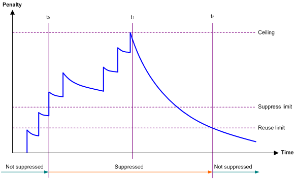
Parameters
· Penalty—The interface has an initial penalty of 0. When the interface flaps, the penalty increases by 1000 for each down event. It does not increase for up events.
· Ceiling—The penalty stops increasing when it reaches the ceiling.
· Suppress-limit—The accumulated penalty that triggers the device to dampen the interface. In dampened state, the interface does not report its state changes to the CPU. For state change events, the interface only generates SNMP traps and log messages
· Reuse-limit—When the accumulated penalty decreases to this reuse threshold, the interface is not dampened. Interface state changes are reported to the upper layers. For each state change, the system also generates an SNMP trap and log message.
· Decay—The amount of time (in seconds) after which a penalty is decreased.
· Max-suppress-time—The maximum amount of time the interface can be dampened. If the penalty is still higher than the reuse threshold when this timer expires, the penalty stops increasing for down events.
The ceiling is equal to 2(Max-suppress-time/Decay) × reuse-limit. It is not user configurable.
Figure 1 shows the change rule of the penalty value. The lines t0 and t2 indicate the start time and end time of the suppression, respectively. The period from t0 to t2 indicates the suppression period, t0 to t1 indicates the max-suppress-time, and t1 to t2 indicates the complete decay period.
Figure 1 Change rule of the penalty value
Configuration restrictions and guidelines
The dampening command does not take effect on the administratively down events. When you execute the shutdown command, the penalty restores to 0, and the interface reports the down event to the upper-layer protocols.
Configuration procedure
To configure dampening on an Ethernet interface:
|
Step |
Command |
Remarks |
|
1. Enter system view. |
system-view |
N/A |
|
2. Enter Ethernet interface view. |
interface interface-type interface-number |
N/A |
|
3. Enable dampening on the interface. |
dampening [ half-life reuse suppress max-suppress-time ] |
By default, interface dampening is disabled on Ethernet interfaces. |
Enabling loopback testing on an Ethernet interface
|
|
CAUTION: After you enable this feature on an Ethernet interface, the interface does not forward data traffic. |
Perform this task to determine whether an Ethernet link works correctly.
Loopback testing includes the following types:
· Internal loopback testing—Tests the device where the Ethernet interface resides. The Ethernet interface sends outgoing packets back to the local device. If the device fails to receive the packets, the device fails.
· External loopback testing—Tests the inter-device link. The Ethernet interface sends incoming packets back to the remote device. If the remote device fails to receive the packets, the inter-device link fails.
Configuration restrictions and guidelines
· The shutdown and loopback commands are exclusive with each other.
· After you enable this feature on an Ethernet interface, the Ethernet interface switches to full duplex mode. After you disable this feature, the Ethernet interface restores to its duplex setting.
Configuration procedure
To enable loopback testing on an Ethernet interface:
|
Step |
Command |
Remarks |
|
1. Enter system view. |
system-view |
N/A |
|
2. Enter Ethernet interface view. |
interface interface-type interface-number |
N/A |
|
3. Enable loopback testing. |
loopback { external | internal } |
By default, loopback testing is disabled on an Ethernet interface. |
Configuring generic flow control on an Ethernet interface
To avoid dropping packets on a link, you can enable generic flow control at both ends of the link. When traffic congestion occurs at the receiving end, the receiving end sends a flow control (Pause) frame to ask the sending end to suspend sending packets. Generic flow control includes the following types:
· TxRx-mode generic flow control—Enabled by using the flow-control command. With TxRx-mode generic flow control enabled, an interface can both send and receive flow control frames:
? When congestion occurs, the interface sends a flow control frame to its peer.
? When the interface receives a flow control frame from its peer, it suspends sending packets to its peer.
· Rx-mode generic flow control—Enabled by using the flow-control receive enable command. With Rx-mode generic flow control enabled, an interface can receive flow control frames, but it cannot send flow control frames:
? When congestion occurs, the interface cannot send flow control frames to its peer.
? When the interface receives a flow control frame from its peer, it suspends sending packets to its peer.
To handle unidirectional traffic congestion on a link, configure the flow-control receive enable command at one end and the flow-control command at the other end. To enable both ends of a link to handle traffic congestion, configure the flow-control command at both ends.
To enable generic flow control on an Ethernet interface:
|
Step |
Command |
Remarks |
|
1. Enter system view. |
system-view |
N/A |
|
2. Enter Ethernet interface view. |
interface interface-type interface-number |
N/A |
|
3. Enable generic flow control. |
· Enable TxRx-mode generic flow control: · Enable Rx-mode generic flow control: |
By default, generic flow control is disabled on an Ethernet interface. |
Setting the statistics polling interval
|
Step |
Command |
Remarks |
|
1. Enter system view. |
system-view |
N/A |
|
2. Enter Ethernet interface view. |
interface interface-type interface-number |
N/A |
|
3. Set the statistics polling interval for the Ethernet interface. |
flow-interval interval |
By default, the statistics polling interval is 300 seconds. |
To display the interface statistics collected in the last statistics polling interval, use the display interface command.
Configuring a Layer 3 Ethernet interface or subinterface
The following matrix shows the feature and hardware compatibility:
|
Hardware series |
Model |
Layer 3 Ethernet interface/subinterface compatibility |
|
WX1800H series |
WX1804H WX1810H WX1820H WX1840H |
Yes |
|
WX3800H series |
WX3820H WX3840H |
No |
|
WX5800H series |
WX5860H |
No |
Setting the MTU for an Ethernet interface or subinterface
The maximum transmission unit (MTU) of an Ethernet interface affects the fragmentation and reassembly of IP packets on the interface. Typically, you do not need to modify the MTU of an interface.
To set the MTU for an Ethernet interface or subinterface:
|
Step |
Command |
Remarks |
|
1. Enter system view. |
system-view |
N/A |
|
2. Enter Ethernet interface or subinterface view. |
interface interface-type { interface-number | interface-number.subnumber } |
N/A |
|
3. Set the MTU of the Ethernet interface or subinterface. |
mtu size |
For information about the default MTU, see Interface Command Reference. |
Setting the MAC address of an Ethernet interface or subinterface
In a network, when the Layer 3 Ethernet interfaces or subinterfaces of different devices have the same MAC address, the devices might fail to communicate correctly. To eliminate the MAC address conflicts, use the mac-address command to modify the MAC addresses of Layer 3 Ethernet interfaces or subinterfaces.
Additionally, when a Layer 3 Ethernet subinterface is created, it uses the MAC address of its main interface by default. As a result, all Layer 3 Ethernet subinterfaces of a Layer 3 Ethernet interface share the same MAC address. To set a different MAC address for a Layer 3 Ethernet subinterface, use the mac-address command.
To set the MAC address of a Layer 3 Ethernet interface or subinterface:
|
Step |
Command |
Remarks |
|
1. Enter system view. |
system-view |
N/A |
|
2. Enter Layer 3 Ethernet interface or subinterface view. |
interface interface-type { interface-number | interface-number.subnumber } |
N/A |
|
3. Set the MAC address of the Layer 3 Ethernet interface or subinterface. |
mac-address mac-address |
The default MAC address of a Layer 3 Ethernet interface varies by device model. The default MAC address of a Layer 3 Ethernet subinterface is the same as the MAC address of its main interface. |
Displaying and maintaining an Ethernet interface or subinterface
Execute display commands in any view and reset commands in user view.
|
Task |
Command |
|
Display interface traffic statistics. |
display counters { inbound | outbound } interface [ interface-type [ interface-number | interface-number.subnumber ] ] |
|
Display traffic rate statistics of interfaces in up state over the last statistics polling interval. |
display counters rate { inbound | outbound } interface [ interface-type [ interface-number | interface-number.subnumber ] ] |
|
Display the operational and status information of the specified interfaces. |
display interface [ interface-type [ interface-number | interface-number.subnumber ] ] [ brief [ description | down ] ] |
|
Display information about dropped packets on the specified interfaces. |
display packet-drop { interface [ interface-type [ interface-number ] ] | summary } |
|
Display the Ethernet statistics. |
display ethernet statistics slot slot-number |
|
Clear interface or subinterface statistics. |
reset counters interface [ interface-type [ interface-number | interface-number.subnumber ] ] |
|
Clear the statistics of dropped packets on the specified interfaces. |
reset packet-drop interface [ interface-type [ interface-number ] ] |
|
Clear the Ethernet statistics. |
reset ethernet statistics [ slot slot-number ] |
Configuring loopback, null, and inloopback interfaces
This chapter describes how to configure a loopback interface, a null interface, and an inloopback interface.
Configuring a loopback interface
A loopback interface is a virtual interface. The physical layer state of a loopback interface is always up unless the loopback interface is manually shut down. Because of this benefit, loopback interfaces are widely used in the following scenarios:
· Configuring a loopback interface address as the source address of the IP packets that the device generates—Because loopback interface addresses are stable unicast addresses, they are usually used as device identifications.
When you configure a rule on an authentication or security server, you can configure it to permit or deny packets carrying the loopback interface address of a device. This simplifies your configuration and achieves the effect of permitting or denying packets that the device generates. To use a loopback interface address as the source address of IP packets, make sure the loopback interface is reachable from the peer by performing routing configuration. All data packets sent to the loopback interface are considered packets sent to the device itself, so the device does not forward these packets.
· Using a loopback interface in dynamic routing protocols—With no router ID configured for a dynamic routing protocol, the system selects the highest loopback interface IP address as the router ID.
To configure a loopback interface:
|
Step |
Command |
Remarks |
|
1. Enter system view. |
system-view |
N/A |
|
2. Create a loopback interface and enter loopback interface view. |
interface loopback interface-number |
N/A |
|
3. Set the interface description. |
description text |
The default setting is interface name Interface (for example, LoopBack0 Interface). |
|
4. Configure the expected bandwidth of the loopback interface. |
bandwidth bandwidth-value |
By default, the expected bandwidth of a loopback interface is 0 kbps. |
|
5. Restore the default settings for the loopback interface. |
default |
N/A |
|
6. Bring up the loopback interface. |
undo shutdown |
By default, a loopback interface is up. |
Configuring a null interface
A null interface is a virtual interface and is always up, but you cannot use it to forward data packets or configure it with an IP address or link layer protocol. The null interface provides a simpler way to filter packets than ACL. You can filter undesired traffic by transmitting it to a null interface instead of applying an ACL. For example, if you specify a null interface as the next hop of a static route to a network segment, any packets routed to the network segment are dropped.
To configure a null interface:
|
Step |
Command |
Remarks |
|
1. Enter system view. |
system-view |
N/A |
|
2. Enter null interface view. |
interface null 0 |
Interface Null 0 is the default null interface on the device and cannot be manually created or removed. Only one null interface, Null 0, is supported on the device. The null interface number is always 0. |
|
3. Set the interface description. |
description text |
The default setting is NULL0 Interface. |
|
4. Restore the default settings for the null interface. |
default |
N/A |
Configuring an inloopback interface
An inloopback interface is a virtual interface created by the system, which cannot be configured or deleted. The physical layer and link layer protocol states of an inloopback interface are always up. All IP packets sent to an inloopback interface are considered packets sent to the device itself and are not forwarded.
Displaying and maintaining loopback, null, and inloopback interfaces
Execute display commands in any view and reset commands in user view.
|
Task |
Command |
|
Display information about the specified or all loopback interfaces. |
display interface [ loopback [ interface-number ] ] [ brief [ description | down ] ] |
|
Display information about the null interface. |
display interface [ null [ 0 ] ] [ brief [ description | down ] ] |
|
Display information about the inloopback interface. |
display interface [ inloopback [ 0 ] ] [ brief [ description | down ] ] |
|
Clear the statistics on the specified or all loopback interfaces. |
reset counters interface loopback [ interface-number ] |
|
Clear the statistics on the null interface. |
reset counters interface [ null [ 0 ] ] |
A
activating
interface (Ethernet single combo), 3
address
interface MAC address (Layer 3 Ethernet), 10
subinterface MAC address (Layer 3 Ethernet), 10
B
bulk
interface configuration, 1
interface configuration display, 2
interface configuration restrictions, 1
C
configuring
interface (Ethernet), 3
interface (inloopback), 13
interface (Layer 3 Ethernet), 9
interface (loopback), 12
interface (null), 12
interface basic settings (Ethernet), 4
interface common settings (Ethernet), 3
interface dampening (Ethernet), 6
interface generic flow control (Ethernet), 8
interface jumbo frame support (Ethernet), 6
interface link mode (Ethernet), 5
subinterface (Layer 3 Ethernet), 9
subinterface basic settings (Ethernet), 4
D
dampening
interface dampening (Ethernet), 6
device
interface configuration (Ethernet), 3
displaying
bulk interface configuration, 2
interface, 13
interface (Ethernet), 10
subinterface (Ethernet), 10
E
enabling
interface loopback testing (Ethernet), 8
Ethernet
interface. See Ethernet interface
subinterface. See Ethernet interface, Ethernet subinterface, subinterface
basic settings configuration, 4
common settings configuration, 3
configuration, 3
configuration (Layer 3), 9
dampening, 6
dampening restrictions, 7
display, 10
generic flow control, 8
jumbo frame support configuration, 6
link mode, 5
loopback test restrictions, 8
loopback testing, 8
MAC address (Layer 3), 10
maintain, 10
MTU setting (Layer 3), 10
single combo interface activation, 3
statistics polling interval, 9
Ethernet subinterface, 3, See also Ethernet interface, Layer 2 Ethernet subinterface, Layer 3 Ethernet subinterface
basic settings, 4
display, 10
MAC address (Layer 3), 10
maintain, 10
external
interface external loopback testing (Ethernet), 8
F
flow control
interface generic flow control (Ethernet), 8
frame
interface jumbo frame support (Ethernet), 6
G
generic flow control (Ethernet interface), 8
I
inloopback interface
configuration, 13
displaying, 13
maintaining, 13
interface
bulk configuration, 1
configuration (inloopback), 12, 13
configuration (loopback), 12, 12
configuration (null), 12, 12
internal
interface internal loopback testing (Ethernet), 8
J
jumbo frame support (Ethernet interface), 6
L
Layer 2
interface configuration (Ethernet), 3
Layer 3
Ethernet interface MAC address, 10
Ethernet subinterface MAC address, 10
interface configuration (Ethernet), 3
subinterface MTU setting (Layer 3 Ethernet), 10
Layer 3 Ethernet interface
configuration, 9
MTU setting, 10
subinterface configuration, 9
link
interface link mode (Ethernet), 5
loopback
interface loopback testing (Ethernet), 8
loopback interface
configuration, 12
displaying, 13
maintaining, 13
M
MAC addressing
interface MAC address (Layer 3 Ethernet), 10
subinterface MAC address (Layer 3 Ethernet), 10
maintaining
interface, 13
interface (Ethernet), 10
subinterface (Ethernet), 10
maximum transmission unit. Use MTU
mode
interface link (Ethernet), 5
subinterface MTU setting (Layer 3 Ethernet), 10
N
network
interface activation (Ethernet single combo), 3
interface basic settings (Ethernet), 4
interface common settings configuration (Ethernet), 3
interface configuration (inloopback), 13
interface configuration (Layer 3 Ethernet), 9
interface configuration (loopback), 12
interface configuration (null), 12
interface dampening (Ethernet), 6
interface generic flow control (Ethernet), 8
interface jumbo frame support (Ethernet), 6
interface link mode (Ethernet), 5
interface loopback testing (Ethernet), 8
interface MAC address (Layer 3 Ethernet), 10
interface MTU setting (Layer 3 Ethernet), 10
interface statistics polling interval (Ethernet), 9
subinterface basic settings (Ethernet), 4
subinterface configuration (Layer 3 Ethernet), 9
subinterface MAC address (Layer 3 Ethernet), 10
subinterface MTU setting (Layer 3 Ethernet), 10
network management
interface bulk configuration, 1
interface configuration (Ethernet), 3
interface configuration (inloopback), 12
interface configuration (loopback), 12
interface configuration (null), 12
null interface
configuration, 12, 12
displaying, 13
maintaining, 13
P
polling
interface statistics polling interval (Ethernet), 9
procedure
activating interface (Ethernet single combo), 3
bulk configuring interfaces, 1
configuring interface (inloopback), 13
configuring interface (Layer 3 Ethernet), 9
configuring interface (loopback), 12
configuring interface (null), 12
configuring interface basic settings (Ethernet), 4
configuring interface common settings (Ethernet), 3
configuring interface dampening (Ethernet), 6
configuring interface generic flow control (Ethernet), 8
configuring interface jumbo frame support (Ethernet), 6
configuring interface link mode (Ethernet), 5
configuring subinterface (Layer 3 Ethernet), 9
configuring subinterface basic settings (Ethernet), 4
displaying bulk interface configuration, 2
displaying interface, 13
displaying interface (Ethernet), 10
displaying subinterface (Ethernet), 10
maintaining interface, 13
maintaining interface (Ethernet), 10
maintaining subinterface (Ethernet), 10
performing interface loopback testing (Ethernet), 8
setting interface MAC address (Layer 3 Ethernet), 10
setting interface MTU (Layer 3 Ethernet), 10
setting interface statistics polling interval (Ethernet), 9
setting subinterface MAC address (Layer 3 Ethernet), 10
setting subinterface MTU (Layer 3 Ethernet), 10
R
restrictions
bulk interface configuration, 1
Ethernet interface loopback test, 8
interface dampening (Ethernet), 7
S
setting
interface MAC address (Layer 3 Ethernet), 10
interface MTU (Layer 3 Ethernet), 10
interface statistics polling interval (Ethernet), 9
subinterface MAC address (Layer 3 Ethernet), 10
subinterface MTU (Layer 3 Ethernet), 10
single combo interface, 3
statistics
interface statistics polling interval (Ethernet), 9
subinterface, 3, See also Ethernet subinterface
switching
interface configuration (Ethernet), 3
interface configuration (inloopback), 12, 13
interface configuration (loopback), 12, 12
interface configuration (null), 12, 12
system
interface bulk configuration, 1