- Table of Contents
- Related Documents
-
| Title | Size | Download |
|---|---|---|
| 02-CFD configuration | 206.25 KB |
Restrictions and guidelines: CFD configuration
Configuring basic CFD settings
Configuring port collaboration
Configuring CFD
About CFD
Connectivity Fault Detection (CFD), which conforms to IEEE 802.1ag Connectivity Fault Management (CFM) and ITU-T Y.1731, is an end-to-end link layer OAM mechanism. CFD is used for link connectivity detection, fault verification, and fault location in Ethernet networks.
Basic CFD concepts
Maintenance domain
A maintenance domain (MD) defines the network or part of the network where CFD plays its role. An MD is identified by its MD name.
Maintenance association
A maintenance association (MA) is a part of an MD. You can configure multiple MAs in an MD as needed. An MA is identified by the MD name + MA name.
In an Ethernet network, an MA serves the specified VLAN or no VLAN. An MA that serves a VLAN is considered to be carrying VLAN attribute. An MA that serves no VLAN is considered to be carrying no VLAN attribute.
Maintenance association end point
An MEP is configured on a port and belongs to an MA.
MEPs define the boundary of the MA. Each MEP is identified by a MEP ID.
The MA to which a MEP belongs defines the VLAN of packets sent by the MEP.
MEPs include inward-facing MEPs and outward-facing MEPs:
· An inward-facing MEP does not send packets to its host port. Rather, it sends packets to other ports on the device. The packets are broadcast in the VLAN that the MA of the MEP serves. Inward-facing MEPs are not supported in the current software version.
· An outward-facing MEP sends packets to its host port.
MEP list
A MEP list is a collection of local MEPs allowed to be configured and the remote MEPs to be monitored in the same MA. It lists all the MEPs configured on different devices in the same MA. The MEPs all have unique MEP IDs. When a MEP receives from a remote device a continuity check message (CCM) carrying a MEP ID not in the MEP list of the MA, it drops the message.
The local device must send CCM messages carrying the Remote Defect Indication (RDI) flag bits. Otherwise, the peer device cannot sense certain failures. When a local MEP has not learned all remote MEPs in the MEP list, the MEPs in the MA might not carry the RDI flag bits in CCMs.
CFD levels
MD levels
To accurately locate faults, CFD introduces eight levels (from 0 to 7) to MDs. The bigger the number, the higher the level and the larger the area covered. Domains can touch but cannot intersect or nest.
MD levels facilitate fault location and make fault location more accurate. As shown in Figure 1, MD_A in light blue touches MD_B in dark blue. If a connectivity fault is detected on the link between Device A and Device D, any of these four devices might fail. If a connectivity fault is also detected at the boundary of MD_B, the failure points can be any of Device B through Device D. If the devices in MD_B can operate correctly, at least Device C is operational.
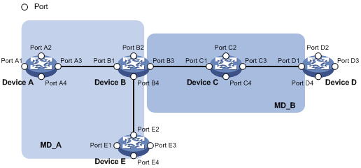
CFD exchanges messages and performs operations on a per-domain basis. By planning MDs correctly in a network, you can use CFD to rapidly locate failure points.
MA and MEP levels
The level of an MA equals the level of the MD to which the MA belongs.
The level of a MEP equals the level of the MD to which the MEP belongs.
CFD grading example
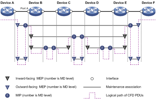
Figure 2 demonstrates a grading example of the CFD module. Four levels of MDs (0, 2, 3, and 5) are designed. The bigger the number, the higher the level and the larger the area covered. MPs are configured on the ports of Device A through Device F. Port A of Device B is configured with the following MPs:
· A level 5 MIP.
· A level 3 inward-facing MEP.
· A level 2 inward-facing MEP.
· A level 0 outward-facing MEP.
Packet processing of MEPs
For an MA carrying VLAN attribute, MEPs of the MA send packets only in the VLAN that the MA serves. The level of packets sent by an MP equals the level of the MD to which the MEP belongs.
For an MA not carrying VLAN attribute, the level of packets sent by an outward-facing MEP equals the level of the MD to which the MEP belongs.
A MEP forwards packets at a higher level without any processing and only processes packets of its level or lower.
CFD functions
CFD functions, which are implemented through the MEPs, include:
· Continuity check (CC).
· Loopback (LB).
· Linktrace (LT).
· Alarm indication signal (AIS).
· Loss measurement (LM).
· Delay measurement (DM).
· Test (TST).
Continuity check
Connectivity faults are usually caused by device faults or configuration errors. Continuity check examines the connectivity between MEPs. This function is implemented through periodic sending of CCMs by the MEPs. A CCM sent by one MEP is intended to be received by all the other MEPs in the same MA. If a MEP fails to receive the CCMs within 3.5 times the sending interval, the link is considered as faulty and a log is generated. When multiple MEPs send CCMs at the same time, the multipoint-to-multipoint link check is achieved. CCM frames are multicast frames.
Loopback
Similar to ping at the IP layer, loopback verifies the connectivity between a source device and a target device. To implement this function, the source MEP sends loopback messages (LBMs) to the target MEP. Depending on whether the source MEP can receive a loopback reply message (LBR) from the target MEP, the link state between the two can be verified.
LBM frames are multicast and unicast frames. The device can send and receive unicast LBM frames, and can receive multicast LBM frames but cannot send multicast LBM frames. LBR frames are unicast frames.
Linktrace
Linktrace is similar to traceroute. It identifies the path between the source MEP and the target MEP. The source MEP sends the linktrace messages (LTMs) to the target MEP. After receiving the messages, the target MEP sends back linktrace reply messages (LTRs) to the source MEP. Based on the reply messages, the source MEP can identify the path to the target MEP. LTM frames are multicast frames and LTRs are unicast frames.
AIS
The AIS function suppresses the number of error alarms reported by MEPs. If a local MEP does not receive any CCM frames from its peer MEP within 3.5 times the CCM transmission interval, it immediately starts sending AIS frames. The AIS frames are sent periodically in the opposite direction of CCM frames. When the peer MEP receives the AIS frames, it suppresses the error alarms locally, and continues to send the AIS frames. If the local MEP receives CCM frames within 3.5 times the CCM transmission interval, it stops sending AIS frames and restores the error alarm function. AIS frames are multicast frames.
LM
The LM function measures the frame loss in a certain direction between a pair of MEPs. The source MEP sends loss measurement messages (LMMs) to the target MEP. The target MEP responds with loss measurement replies (LMRs). The source MEP calculates the number of lost frames according to the counter values of the two consecutive LMRs (the current LMR and the previous LMR). LMMs and LMRs are unicast frames.
The LM function can be implemented in one of the following ways:
· Short-period LM—The source MEP sends a configurable number of LMMs at a configurable interval.
· Continual LM—The source MEP continually sends LMMs at a configurable interval until continual LM is administratively disabled. To view the test result, use the display cfd slm history command on the target MEP.
Continual LM can work with port collaboration. Port collaboration shuts down or blocks a port based on the continual LM result. For more information about port collaboration, see "Port collaboration."
DM
The DM function measures frame delays between two MEPs, including the following types:
· One-way frame delay measurement
The source MEP sends a one-way delay measurement (1DM) frame, which carries the transmission time, to the target MEP. When the target MEP receives the 1DM frame, it does the following:
¡ Records the reception time.
¡ Calculates and records the link transmission delay and jitter (delay variation) according to the transmission time and reception time.
1DM frames are unicast frames.
· Two-way frame delay measurement
The source MEP sends a delay measurement message (DMM), which carries the transmission time, to the target MEP. When the target MEP receives the DMM, it responds with a delay measurement reply (DMR). The DMR carries the reception time and transmission time of the DMM and the transmission time of the DMR. When the source MEP receives the DMR, it does the following:
¡ Records the DMR reception time.
¡ Calculates the link transmission delay and jitter according to the DMR reception time and DMM transmission time.
DMM frames and DMR frames are unicast frames.
The two-way DM function can be implemented in one of the following ways:
¡ Short-period two-way DM—The source MEP sends a configurable number of DMMs at a configurable interval.
¡ Continual two-way DM—The source MEP continually sends DMMs at a configurable interval until continual two-way DM is administratively disabled. To view the test result, use the display cfd dm two-way history command on the target MEP.
Continual two-way DM can work with port collaboration. Port collaboration shuts down or blocks a port based on the continual two-way DM result. For more information about port collaboration, see "Port collaboration."
TST
The TST function tests the bit errors between two MEPs. The source MEP sends a TST frame, which carries the test pattern, such as pseudo random bit sequence (PRBS) or all-zero, to the target MEP. When the target MEP receives the TST frame, it determines the bit errors by calculating and comparing the content of the TST frame. TST frames are unicast frames.
This function can be implemented in one of the following ways:
· Short-period TST—The source MEP sends a configurable number of TST frames at a configurable interval.
· Continual TST—The source MEP continually sends TST frames at a configurable interval until continual TST is administratively disabled. To view the test result, use the display cfd tst history command on the target MEP.
Continual TST can work with port collaboration. Port collaboration shuts down or blocks a port based on the continual TST result. For more information about port collaboration, see "Port collaboration."
Port collaboration
Port collaboration shuts down or blocks ports based on the result of link detection performed by outward-facing MEPs.
Triggering events
Port collaboration can be triggered by the following events:
· Continuity check expires.
· The link transmission delay in continual two-way DM reaches or exceeds the upper limit, or reaches or falls below the lower limit.
· The CCMs with the RDI flag bit set are received.
· The packet loss ratio in continual LM reaches or exceeds the upper limit, or reaches or falls below the lower limit.
· The bit error ratio in continual TST reaches or exceeds the upper limit, or reaches or falls below the lower limit.
You can specify both triggering events for an interface. Both triggering events can take effect.
Triggered actions
Port collaboration takes one of the following triggered actions:
· Blocks the port by changing its link layer protocol state to DOWN (CFD). The port cannot send or receive any data packets.
· Shuts down the port by changing its physical state to CFD DOWN. The port cannot send or receive any data packets or protocol packets.
Link recovery
If a port is blocked by CFD, it can automatically come up when the link recovers, except that the block action is triggered by continual LM. To bring up the port blocked in continual LM, execute the undo cfd port-trigger slm action or cfd slm port-trigger up-delay command.
If a port is shut down by CFD, it cannot automatically come up when the link recovers. To bring up the port, you must execute the undo shutdown or undo cfd port-trigger command.
Protocols and standards
· IEEE 802.1ag, Virtual Bridged Local Area Networks Amendment 5: Connectivity Fault Management
· ITU-T Y.1731, OAM functions and mechanisms for Ethernet based networks
Restrictions and guidelines: CFD configuration
When you configure CFD, follow these restrictions and guidelines:
· Configure CC before you use the MEP ID of the remote MEP to configure other CFD functions. This restriction does not apply when you use the MAC address of the remote MEP to configure other CFD functions.
· A port blocked by the spanning tree feature cannot receive or send CFD messages except that it is configured as an outward-facing MEP.
For more information about the spanning tree feature, see Layer 2—LAN Switching Configuration Guide.
CFD tasks at a glance
To configure CFD, perform the following tasks:
1. Configuring basic CFD settings
a. Enabling CFD
b. Configuring service instances
b. (Optional.) Configuring LB
c. (Optional.) Configuring LT
d. (Optional.) Configuring AIS
e. (Optional.) Configuring LM
f. (Optional.) Configuring one-way DM
g. (Optional.) Configuring two-way DM
h. (Optional.) Configuring TST
3. (Optional.) Configuring port collaboration
Prerequisites for CFD
For CFD to work correctly, design the network by performing the following tasks:
· Grade the MDs in the entire network, and define the boundary of each MD.
· Assign a name for each MD. Make sure the devices in the same MD use the same MD name.
· Define the MA in each MD according to the VLAN you want to monitor.
· Assign a name for each MA. Make sure that the devices in the same MA in the same MD use the same MA name.
· Determine the MEP list of each MA in each MD. Make sure devices in the same MA maintain the same MEP list.
Configuring basic CFD settings
Enabling CFD
1. Enter system view.
system-view
2. Enable CFD.
cfd enable
By default, CFD is disabled.
Configuring service instances
About service instances
Before configuring the MEPs and MIPs, you must first configure service instances. A service instance is a set of service access points (SAPs), and belongs to an MA in an MD.
The MD and MA define the level attribute and VLAN attribute of the messages handled by the MEPs in a service instance. The MEPs of the MA that carries no VLAN attribute do not belong to any VLAN.
Procedure
1. Enter system view.
system-view
2. Create an MD.
cfd md md-name [ index index-value ] level level-value [ md-id { dns dns-name | mac mac-address subnumber | none } ]
3. Create a service instance.
cfd service-instance instance-id ma-id { icc-based ma-name | integer ma-num | string ma-name | vlan-based [ vlan-id ] } [ ma-index index-value ] md md-name [ vlan vlan-id ]
Configuring MEPs
About MEPs
CFD is implemented through various operations on MEPs. As a MEP is configured on a service instance, the MD level and VLAN attribute of the service instance become the attribute of the MEP.
Restrictions and guidelines
You can specify an interface as the MEP for only one of the non-VLAN-specific MAs at the same level. In addition, the MEP must be outward facing.
To create a MEP for an MA that carries VLAN attribute on a Layer 3 Ethernet interface, make sure the following requirements are met:
· The device supports subinterfaces.
· The subinterfaces support VLAN termination. For more information about VLAN termination, see Layer 2—LAN Switching Configuration Guide.
If a MEP in a non-VLAN-specific MA does not receive a CCM message within 3.5 CCM intervals from a remote MEP, the local MEP sets its interface to link down state.
Prerequisites
Before you configure MEPs, you must configure service instances.
Procedure
1. Enter system view.
system-view
2. Configure a MEP list.
cfd meplist mep-list service-instance instance-id
All created MEPs must be included in the configured MEP list.
3. Enter Layer 3 Ethernet interface view.
interface interface-type interface-number
4. Create a MEP.
cfd mep mep-id service-instance instance-id outbound
Configuring CFD functions
Configuring CC
About CC
After the CC function is configured, MEPs in an MA can periodically send CCM frames to maintain connectivity.
You must configure CC before you use the MEP ID of the remote MEP to configure other CFD functions. This restriction does not apply when you use the MAC address of the remote MEP to configure other CFD functions.
When the lifetime of a CCM frame expires, the link to the sending MEP is considered disconnected. When setting the CCM interval, use the settings described in Table 1.
Table 1 CCM interval field encoding
|
CCM interval field |
Transmission interval |
Maximum CCM lifetime |
|
1 |
10/3 milliseconds |
35/3 milliseconds |
|
2 |
10 milliseconds |
35 milliseconds |
|
3 |
100 milliseconds |
350 milliseconds |
|
4 |
1 second |
3.5 seconds |
|
5 |
10 seconds |
35 seconds |
|
6 |
60 seconds |
210 seconds |
|
7 |
600 seconds |
2100 seconds |
|
|
NOTE: · The value range for the interval field is 1 to 7. The values 1 and 2 are not supported in the current software version. · The CCM messages with an interval field value of 1 to 3 are short-interval CCM messages. The CCM messages with an interval field value of 4 to 7 are long-interval CCM messages. |
Restrictions and guidelines
When you configure the CCM interval, follow these restrictions and guidelines:
· Configure the same CCM interval field value for all MEPs in the same MA.
· After the CCM interval field is modified, the MEP must wait for another CCM interval before sending CCMs.
· If the device cannot process short-interval CCM messages, setting the CCM interval field value to smaller than 4 might cause the CC function to operate unsteadily.
A card discards short-interval CCM messages to reduce impact on CPU performance. As a best practice, configure the same long CCM interval for all MEPs in an MA.
Procedure
1. Enter system view.
system-view
2. (Optional.) Set the CCM interval field.
cfd cc interval interval-value service-instance instance-id
By default, the interval field value is 4.
Enter Layer 3 Ethernet interface view.
interface interface-type interface-number
3. Enable CCM sending on a MEP.
cfd cc service-instance instance-id mep mep-id enable
By default, CCM sending is disabled on a MEP.
Configuring LB
To verify the link state between the local MEP and the remote MEP, execute the following command in any view:
cfd loopback service-instance instance-id mep mep-id { target-mac mac-address | target-mep target-mep-id } [ number number ]
Configuring LT
About LT
LT can trace the path between source and target MEPs, and can locate link faults by automatically sending LT messages. The two functions are implemented in the following way:
· Tracing path—The source MEP first sends LTM messages to the target MEP. Based on the LTR messages in response to the LTM messages, the path between the two MEPs is identified.
· LT messages automatic sending—If the source MEP fails to receive CCM frames from the target MEP within 3.5 times the transmission interval, it considers the link faulty. The source MEP then sends LTM frames, with the TTL field set to the maximum value 255, to the target MEP. Based on the returned LTRs, the fault source is located.
Prerequisites
Before you configure LT on a MEP in an MA carrying VLAN attribute, create the VLAN to which the MA belongs.
Procedure
1. Identify the path between a source MEP and a target MEP.
cfd linktrace service-instance instance-id mep mep-id { target-mac mac-address | target-mep target-mep-id } [ ttl ttl-value ]
This command is available in any view.
2. Enter system view.
system-view
3. Enable LT messages automatic sending.
cfd linktrace auto-detection [ size size-value ]
By default, LT messages automatic sending is disabled.
Configuring AIS
About AIS
The AIS function suppresses the number of error alarms reported by MEPs.
Restrictions and guidelines
If you enable AIS without configuring a correct AIS frame transmission level, the MEP can suppress error alarms, but cannot send AIS frames to MDs with higher level.
Procedure
1. Enter system view.
system-view
2. Enable AIS.
cfd ais enable
By default, AIS is disabled.
3. Configure the AIS frame transmission level.
cfd ais level level-value service-instance instance-id
By default, the AIS frame transmission level is not configured.
The AIS frame transmission level must be higher than the MD level of the service instance.
4. Configure the AIS frame transmission interval.
cfd ais period period-value service-instance instance-id
By default, the AIS frame transmission interval is 1 second.
Configuring LM
About LM
The LM function measures frame loss between MEPs. Frame loss statistics include the number of lost frames, the frame loss ratio, and the average number of lost frames for the source and target MEPs.
Configuring short-period LM
To configure short-period LM, execute the following command in any view:
cfd slm service-instance instance-id mep mep-id { target-mac mac-address | target-mep target-mep-id } [ dot1p dot1p-value ] [ number number ] [ interval interval ]
Configuring continual LM
1. Enter system view.
system-view
2. Configure continual LM.
cfd slm continual service-instance instance-id mep mep-id { target-mac mac-address | target-mep target-mep-id } [ dot1p dot1p-value ] [ interval interval ]
By default, continual LM is not configured.
Configuring one-way DM
About one-way DM
The one-way DM function measures the one-way frame delay between two MEPs, and monitors and manages the link transmission performance.
Restrictions and guidelines
One-way DM requires that the time settings at the source MEP and the target MEP be the same. For the purpose of frame delay variation measurement, the requirement can be relaxed.
To view the test result, use the display cfd dm one-way history command on the target MEP.
Procedure
To configure one-way DM, execute the following command in any view:
cfd dm one-way service-instance instance-id mep mep-id { target-mac mac-address | target-mep target-mep-id } [ number number ]
Configuring two-way DM
About two-way DM
The two-way DM function measures the two-way frame delay, average two-way frame delay, and two-way frame delay variation between two MEPs. It also monitors and manages the link transmission performance.
Configuring short-period two-way DM
To configure two-way DM, execute the following command in any view:
cfd dm two-way service-instance instance-id mep mep-id { target-mac mac-address | target-mep target-mep-id } dot1p dot1p-value ] [ number number ] [ interval interval ]
Configuring continual two-way DM
1. Enter system view.
system-view
2. Configure continual two-way DM.
cfd dm two-way continual service-instance instance-id mep mep-id { target-mac mac-address | target-mep target-mep-id } [ dot1p dot1p-value ] [ interval interval ]
By default, continual two-way DM is not configured.
Configuring TST
About TST
The TST function detects bit errors on a link, and monitors and manages the link transmission performance.
Restrictions and guidelines
To view the test result, use the display cfd tst history command on the target MEP.
Configuring short-period TST
To configure short-period TST, execute the following command in any view:
cfd tst service-instance instance-id mep mep-id { target-mac mac-address | target-mep target-mep-id } [ number number ] [ length-of-test length ] [ pattern-of-test { all-zero | prbs } [ with-crc ] ]
Configuring continual TST
1. Enter system view.
system-view
2. Configure continual TST.
cfd tst continual service-instance instance-id mep mep-id { target-mac mac-address | target-mep target-mep-id } [ length-of-test length ] [ pattern-of-test { all-zero | prbs } [ with-crc ] ] [ interval interval ]
By default, continual TST is not configured.
Configuring port collaboration
Restrictions and guidelines
Port collaboration takes effect only on the ports with outward-facing MEPs configured.
Configuring port collaboration for CC
1. Enter system view.
system-view
2. Enter Layer 2 or Layer 3 Ethernet interface view or Layer 2 aggregate interface view.
interface interface-type interface-number
3. Specify the port collaboration action for CC.
cfd port-trigger cc-expire action { block | shutdown }
By default, no port collaboration action is specified for CC.
Configuring port collaboration for continual two-way DM
1. Enter system view.
system-view
2. Enter Layer 2 or Layer 3 Ethernet interface view or Layer 2 aggregate interface view.
interface interface-type interface-number
3. Specify the port collaboration action for continual two-way DM.
cfd port-trigger dm action { block | shutdown }
By default, no port collaboration action is specified for continual two-way DM.
4. Return to system view.
quit
5. Configure the lower limit and upper limit for continual two-way DM.
cfd dm two-way threshold service-instance instance-id mep mep-id { lower-limit lower-limit | upper-limit upper-limit } *
By default, the lower limit and upper limit for continual two-way DM are 0 and 4294967295 microseconds, respectively.
Configuring port collaboration for RDI
1. Enter system view.
system-view
2. Enter Layer 2 or Layer 3 Ethernet interface view or Layer 2 aggregate interface view.
interface interface-type interface-number
3. Specify the port collaboration action for RDI.
cfd port-trigger rdi action { block | shutdown }
By default, no port collaboration action is specified for RDI.
Configuring port collaboration for continual LM
1. Enter system view.
system-view
2. Enter Layer 2 or Layer 3 Ethernet interface view or Layer 2 aggregate interface view.
interface interface-type interface-number
3. Specify the port collaboration action for continual LM.
cfd port-trigger slm action { block | shutdown }
By default, no port collaboration action is specified for continual LM.
4. Return to system view.
quit
5. Configure the lower limit and upper limit for continual LM.
cfd slm { far-end | near-end } threshold service-instance instance-id mep mep-id { lower-limit lower-limit | upper-limit upper-limit } *
By default, the lower limit and upper limit for continual LM are 0 and 100%, respectively.
6. Enable automatic port recovery for continual LM and set the delay time for automatic recovery.
cfd slm port-trigger up-delay delay
By default, the undo cfd port-trigger slm action command is required to bring up a port blocked in continual LM.
Configuring port collaboration for continual TST
1. Enter system view.
system-view
2. Enter Layer 2 or Layer 3 Ethernet interface view or Layer 2 aggregate interface view.
interface interface-type interface-number
3. Specify the port collaboration action for continual TST.
cfd port-trigger tst action { block | shutdown }
By default, no port collaboration action is specified for continual TST.
4. Return to system view.
quit
5. Configure the lower limit and upper limit for continual TST.
cfd tst threshold service-instance instance-id mep mep-id { lower-limit lower-limit | upper-limit upper-limit } *
By default, the lower limit and upper limit for continual TST are 0 and 100%, respectively.
Display and maintenance commands for CFD
Execute display commands in any view and reset commands in user view.
|
Task |
Command |
|
Display the AIS configuration and information on the specified MEP. |
display cfd ais [ service-instance instance-id [ mep mep-id ] ] |
|
Display the one-way DM result on the specified MEP. |
display cfd dm one-way history [ service-instance instance-id [ mep mep-id ] ] |
|
Display LTR information received by a MEP. |
display cfd linktrace-reply [ service-instance instance-id [ mep mep-id ] ] |
|
Display the content of the LTR messages received as responses to the automatically sent LTMs. |
display cfd linktrace-reply auto-detection [ size size-value ] |
|
Display MD configuration information. |
display cfd md |
|
Display the attribute and running information of the MEPs. |
display cfd mep mep-id service-instance instance-id |
|
Display the MEP list in a service instance. |
display cfd meplist [ service-instance instance-id ] |
|
Display MP information. |
display cfd mp [ interface interface-type interface-number ] |
|
Display information about a remote MEP. |
display cfd remote-mep service-instance instance-id mep mep-id |
|
Display service instance configuration. |
display cfd service-instance [ instance-id ] |
|
Display CFD status. |
display cfd status |
|
Display the TST result on the specified MEP. |
display cfd tst history [ service-instance instance-id [ mep mep-id ] ] |
|
Clear the one-way DM result on the specified MEP. |
reset cfd dm one-way history [ service-instance instance-id [ mep mep-id ] ] |
|
Clear the TST result on the specified MEP. |
reset cfd tst [ service-instance instance-id [ mep mep-id ] ] |
CFD configuration examples
Example: Configuring CFD in an Ethernet network
Network configuration
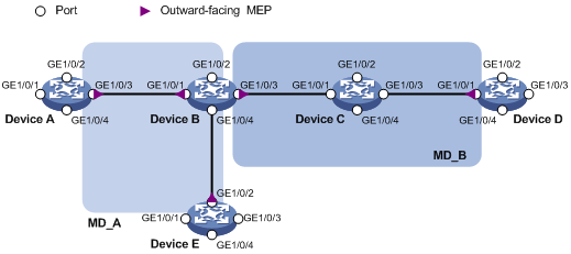
As shown in Figure 3:
· The network comprises five devices and is divided into two MDs: MD_A (level 5) and MD_B (level 3). The MAs in the two MDs all serve VLAN 100. Assume that the MAC addresses of Device A through Device E are 0010-FC01-6511, 0010-FC02-6512, 0010-FC03-6513, 0010-FC04-6514, and 0010-FC05-6515, respectively.
· MD_A has three edge ports: GigabitEthernet 1/0/3 on Device A, GigabitEthernet 1/0/1 on Device B, and GigabitEthernet 1/0/2 on Device E. MD_B has two edge ports: GigabitEthernet 1/0/3 on Device B and GigabitEthernet 1/0/1 on Device D. They are both outward-facing MEPs.
· Configure CC to monitor the connectivity among all the MEPs in MD_A and MD_B. Configure LB to locate link faults
· Configure port collaboration on GigabitEthernet 1/0/3 of Device B. After the outward-facing MEP on the interface detects a link fault, the interface is shut down or blocked.
· After the status information of the entire network is obtained, use LT, LM, one-way DM, two-way DM, and TST to detect link faults.
Procedure
1. Configure a VLAN and assign ports to it:
On each device shown in Figure 3, create VLAN 100 and assign ports GigabitEthernet 1/0/1 through GigabitEthernet 1/0/4 to VLAN 100.
2. Enable CFD:
# Enable CFD on Device A.
<DeviceA> system-view
[DeviceA] cfd enable
# Configure Device B through Device E in the same way Device A is configured. (Details not shown.)
3. Configure service instances:
# Create MD_A (level 5) on Device A, and create service instance 1 (in which the MA is identified by a VLAN and serves VLAN 100).
[DeviceA] cfd md MD_A level 5
[DeviceA] cfd service-instance 1 ma-id vlan-based md MD_A vlan 100
# Configure Device E in the same way Device A is configured. (Details not shown.)
# Create MD_A (level 5) on Device B, and create service instance 1 (in which the MA is identified by a VLAN and serves VLAN 100).
[DeviceB] cfd md MD_A level 5
[DeviceB] cfd service-instance 1 ma-id vlan-based md MD_A vlan 100
# Create MD_B (level 3), and create service instance 2 (in which the MA is identified by a VLAN and serves VLAN 100).
[DeviceB] cfd md MD_B level 3
[DeviceB] cfd service-instance 2 ma-id vlan-based md MD_B vlan 100
# Configure Device D in the same way Device B is configured. (Details not shown.)
# Create MD_B (level 3) on Device C, and create service instance 2 (in which the MA is identified by a VLAN and serves VLAN 100).
[DeviceC] cfd md MD_B level 3
[DeviceC] cfd service-instance 2 ma-id vlan-based md MD_B vlan 100
4. Configure MEPs:
# On Device A, configure a MEP list in service instance 1, and create outward-facing MEP 1001 in service instance 1 on GigabitEthernet 1/0/3.
[DeviceA] cfd meplist 1001 4002 5001 service-instance 1
[DeviceA] interface gigabitethernet 1/0/3
[DeviceA-GigabitEthernet1/0/3] cfd mep 1001 service-instance 1 outbound
[DeviceA-GigabitEthernet1/0/3] quit
# Configure VLAN termination on GigabitEthernet 1/0/3.100.
[DeviceA] interface GigabitEthernet1/0/3.100
[DeviceA-GigabitEthernet1/0/3.100] vlan-type dot1q vid 100
[DeviceA-GigabitEthernet1/0/3.100] quit
# On Device B, configure a MEP list in service instances 1 and 2.
[DeviceB] cfd meplist 1001 4002 5001 service-instance 1
[DeviceB] cfd meplist 2001 4001 service-instance 2
# Create outward-facing MEP 5001 in service instance 1 on GigabitEthernet 1/0/1.
[DeviceB] interface gigabitethernet 1/0/1
[DeviceB-GigabitEthernet1/0/1] cfd mep 5001 service-instance 1 outbound
[DeviceB-GigabitEthernet1/0/1] quit
# Create outward-facing MEP 2001 in service instance 2 on GigabitEthernet 1/0/3.
[DeviceB] interface gigabitethernet 1/0/3
[DeviceB-GigabitEthernet1/0/3] cfd mep 2001 service-instance 2 outbound
[DeviceB-GigabitEthernet1/0/3] quit
# Configure VLAN termination on GigabitEthernet 1/0/1.100 and GigabitEthernet 1/0/3.100.
[DeviceB] interface GigabitEthernet1/0/1.100
[DeviceB-GigabitEthernet1/0/1.100] vlan-type dot1q vid 100
[DeviceB-GigabitEthernet1/0/1.100] quit
[DeviceB] interface GigabitEthernet1/0/3.100
[DeviceB-GigabitEthernet1/0/3.100] vlan-type dot1q vid 100
[DeviceB-GigabitEthernet1/0/3.100] quit
# On Device D, configure a MEP list in service instance 2.
[DeviceD] cfd meplist 2001 4001 service-instance 2
# Create outward-facing MEP 4001 in service instance 2 on GigabitEthernet 1/0/1.
[DeviceD] interface gigabitethernet 1/0/1
[DeviceD-GigabitEthernet1/0/1] cfd mep 4001 service-instance 2 outbound
[DeviceD-GigabitEthernet1/0/1] quit
# Configure VLAN termination on GigabitEthernet1/0/1.100.
[DeviceD] interface gigabitethernet 1/0/1.100
[DeviceD-GigabitEthernet1/0/1.100] vlan-type dot1q vid 100
[DeviceD-GigabitEthernet1/0/1.100] quit
# On Device E, configure a MEP list in service instance 1.
[DeviceE] cfd meplist 1001 4002 5001 service-instance 1
# Create outward-facing MEP 4002 in service instance 1 on GigabitEthernet 1/0/1.
[DeviceE] interface gigabitethernet 1/0/1
[DeviceE-GigabitEthernet1/0/1] cfd mep 4002 service-instance 1 outbound
[DeviceE-GigabitEthernet1/0/1] quit
# Configure VLAN termination on GigabitEthernet1/0/1.100.
[DeviceE] interface GigabitEthernet1/0/1.100
[DeviceE-GigabitEthernet1/0/1.100] vlan-type dot1q vid 100
[DeviceE-GigabitEthernet1/0/1.100] quit
5. Configure CC:
# On Device A, enable the sending of CCM frames for MEP 1001 in service instance 1 on GigabitEthernet 1/0/3.
[DeviceA] interface gigabitethernet 1/0/3
[DeviceA-GigabitEthernet 1/0/3] cfd cc service-instance 1 mep 1001 enable
[DeviceA-GigabitEthernet 1/0/3] quit
# On Device B, enable the sending of CCM frames for MEP 5001 in service instance 1 on GigabitEthernet 1/0/1, and enable the sending of CCM frames for MEP 2001 in service instance 2 on GigabitEthernet 1/0/3.
[DeviceB] interface gigabitethernet 1/0/1
[DeviceB-GigabitEthernet1/0/1] cfd cc service-instance 1 mep 5001 enable
[DeviceB-GigabitEthernet1/0/1] quit
[DeviceB] interface gigabitethernet 1/0/3
[DeviceB-GigabitEthernet1/0/3] cfd cc service-instance 2 mep 2001 enable
[DeviceB-GigabitEthernet1/0/3] quit
# On Device D, enable the sending of CCM frames for MEP 4001 in service instance 2 on GigabitEthernet 1/0/1.
[DeviceD] interface gigabitethernet 1/0/1
[DeviceD-GigabitEthernet1/0/1] cfd cc service-instance 2 mep 4001 enable
[DeviceD-GigabitEthernet1/0/1] quit
# On Device E, enable the sending of CCM frames for MEP 4002 in service instance 1 on GigabitEthernet 1/0/1.
[DeviceE] interface gigabitethernet 1/0/1
[DeviceE-GigabitEthernet1/0/1] cfd cc service-instance 1 mep 4002 enable
[DeviceE-GigabitEthernet1/0/1] quit
6. Configure port collaboration on GigabitEthernet 1/0/3:
# Specify the triggering event as cc-expire and triggered action as shutdown for port collaboration on the interface.
[DeviceB] interface gigabitethernet 1/0/3
[DeviceB-GigabitEthernet1/0/3] cfd port-trigger cc-expire action shutdown
# Specify the triggering event as rdi and triggered action as block for port collaboration on the interface.
[DeviceB-GigabitEthernet1/0/3] cfd port-trigger rdi action block
# Specify the triggering event as dm and triggered action as shutdown for port collaboration on the interface.
[DeviceB-GigabitEthernet1/0/3] cfd port-trigger dm action shutdown
# Specify the triggering event as slm and triggered action as block for port collaboration on the interface.
[DeviceB-GigabitEthernet1/0/3] cfd port-trigger slm action block
# Specify the triggering event as tst and triggered action as shutdown for port collaboration on the interface.
[DeviceB-GigabitEthernet1/0/3] cfd port-trigger tst action shutdown
[DeviceB-GigabitEthernet1/0/3] quit
Verifying the configuration
1. Verify the LB function when the CC function detects a link fault:
# Enable LB on Device A to check the status of the link between MEP 1001 and MEP 5001 in service instance 1.
[DeviceA] cfd loopback service-instance 1 mep 1001 target-mep 5001
Loopback to MEP 5001 with the sequence number start from 1001-43404:
Reply from 0010-fc05-6512: sequence number=1001-43404 time=5ms
Reply from 0010-fc05-6512: sequence number=1001-43405 time=5ms
Reply from 0010-fc05-6512: sequence number=1001-43406 time=5ms
Reply from 0010-fc05-6512: sequence number=1001-43407 time=5ms
Reply from 0010-fc05-6512: sequence number=1001-43408 time=5ms
Sent: 5 Received: 5 Lost: 0
2. Verify the LT function after the CC function obtains the status information of the entire network:
# Identify the path between MEP 1001 and MEP 5001 in service instance 1 on Device A.
[DeviceA] cfd linktrace service-instance 1 mep 1001 target-mep 5001
Linktrace to MEP 5001 with the sequence number 1001-43462:
MAC address TTL Last MAC Relay action
0010-fc05-6512 63 0010-fc02-6512 Hit
3. Verify the LM function after the CC function obtains the status information of the entire network:
# Use short-period LM to test the frame loss from MEP 1001 to MEP 5001 in service instance 1 on Device A.
[DeviceA] cfd slm service-instance 1 mep 1001 target-mep 5001
Reply from 0010-fc04-6512
Far-end frame loss: 10 Near-end frame loss: 20
Reply from 0010-fc04-6512
Far-end frame loss: 40 Near-end frame loss: 40
Reply from 0010-fc04-6512
Far-end frame loss: 0 Near-end frame loss: 10
Reply from 0010-fc04-6512
Far-end frame loss: 30 Near-end frame loss: 30
Average
Far-end frame loss: 20 Near-end frame loss: 25
Far-end frame loss rate: 25.00% Near-end frame loss rate: 32.00%
Send LMMs: 5 Received: 5 Lost: 0
# Use continual LM to test the frame loss from MEP 1001 to MEP 5001 in service instance 1 on Device A.
[DeviceA] cfd slm continual service-instance 1 mep 1001 target-mep 5001
# Display the LM result on MEP 5001 in service instance 1 on Device A.
[DeviceA] display cfd slm history service-instance 1 mep 5001
Service instance: 1
MEP ID: 1001
Send status: Testing
Reply from 0010-fc04-6512
Far-end frame loss: 10 Near-end frame loss: 20
Reply from 0010-fc04-6512
Far-end frame loss: 40 Near-end frame loss: 40
Reply from 0010-fc04-6512
Far-end frame loss: 0 Near-end frame loss: 10
Reply from 0010-fc04-6512
Far-end frame loss: 30 Near-end frame loss: 30
Reply from 0010-f00-6512
Far-end frame loss: 20 Near-end frame loss: 25
Average:
Far-end frame loss: 20 Near-end frame loss: 25
Far-end frame loss rate: 25.00% Near-end frame loss rate: 32.00%
Packet statistics:
Sent LMMs: 100 Received: 100 Lost: 0
4. Verify the one-way DM function after the CC function obtains the status information of the entire network:
# Test the one-way frame delay from MEP 1001 to MEP 5001 in service instance 1 on Device A.
[DeviceA] cfd dm one-way service-instance 1 mep 1001 target-mep 5001
5 1DMs have been sent. Please check the result on the remote device.
# Display the one-way DM result on MEP 5001 in service instance 1 on Device B.
[DeviceB] display cfd dm one-way history service-instance 1 mep 5001
Service instance: 1
MEP ID: 5001
Sent 1DM total number: 0
Received 1DM total number: 5
Frame delay: 10ms 9ms 11ms 5ms 5ms
Delay average: 8ms
Delay variation: 5ms 4ms 6ms 0ms 0ms
Variation average: 3ms
5. Verify the two-way DM function after the CC function obtains the status information of the entire network:
# Use short-period two-way DM to test the two-way frame delay from MEP 1001 to MEP 5001 in service instance 1 on Device A.
[DeviceA] cfd dm two-way service-instance 1 mep 1001 target-mep 5001
Frame delay:
Reply from 0010-fc04-6512: 10us
Reply from 0010-fc04-6512: 9us
Reply from 0010-fc04-6512: 11us
Reply from 0010-fc04-6512: 5us
Reply from 0010-fc04-6512: 5us
Average: 8us
Sent DMMs: 5 Received: 5 Lost: 0
Frame delay variation: 1us 2us 6us 0us
Average: 2us
# Use continual two-way DM to test the two-way frame delay from MEP 1001 to MEP 5001 in service instance 1 on Device A.
[DeviceA] cfd dm two-way continual service-instance 1 mep 1001 target-mep 5001
# Display the two-way DM result on MEP 1001 in service instance 1 on Device A.
[DeviceA] display cfd dm two-way history service-instance 1 mep 1001
Service instance: 1
MEP ID: 1001
Send status: Testing
Frame delay:
Reply from 0010-fc04-6512: 564us
Reply from 0010-fc04-6512: 606us
Reply from 0010-fc04-6512: 650us
Reply from 0010-fc04-6512: 626us
Reply from 0010-fc04-6512: 660us
Average: 621us
Frame delay variation: 42us 44us 24us 34us
Average: 36us
Packet statistics:
Sent DMMs: 5 Received: 5 Lost: 0
6. Verify the TST function after the CC function obtains the status information of the entire network:
# Use short-period TST to test the bit errors on the link from MEP 1001 to MEP 5001 in service instance 1 on Device A.
[DeviceA] cfd tst service-instance 1 mep 1001 target-mep 5001
5 TSTs have been sent. Please check the result on the remote device.
# Use continual TST to test the bit errors on the link from MEP 1001 to MEP 5001 in service instance 1 on Device A.
[DeviceA] cfd tst continual service-instance 1 mep 1001 target-mep 5001
# Display the TST result on MEP 5001 in service instance 1 on Device B.
[DeviceB] display cfd tst history service-instance 1 mep 5001
Service instance: 1
MEP ID: 5001
Received from 0010-fc01-6511, Bit True, sequence number 0
Received from 0010-fc01-6511, Bit True, sequence number 1
Received from 0010-fc01-6511, Bit True, sequence number 2
Received from 0010-fc01-6511, Bit True, sequence number 3
Received from 0010-fc01-6511, Bit True, sequence number 4
Sent TST total number: 7
Received TST total number: 5
Received bit error TST number: 0
Percentage of error messages: 0.00%