- Table of Contents
-
- 07-Layer 3—IP Services Configuration Guide
- 00-Preface
- 01-ARP configuration
- 02-IP addressing configuration
- 03-DHCP configuration
- 04-DNS configuration
- 05-NAT configuration
- 06-IP forwarding basics configuration
- 07-Fast forwarding configuration
- 08-Multi-CPU packet distribution configuration
- 09-Adjacency table configuration
- 10-IRDP configuration
- 11-IP performance optimization configuration
- 12-UDP helper configuration
- 13-IPv6 basics configuration
- 14-DHCPv6 configuration
- 15-IPv6 fast forwarding configuration
- 16-Tunneling configuration
- 17-GRE configuration
- 18-ADVPN configuration
- 19-WAAS configuration
- 20-AFT configuration
- 21-Lighttpd service configuration
- 22-Web caching configuration
- Related Documents
-
| Title | Size | Download |
|---|---|---|
| 06-IP forwarding basics configuration | 55.35 KB |
Configuring IP forwarding basic settings········································ 1
About FIB table······················································································································ 1
Enabling last hop holding······································································································· 1
Display and maintenance commands for FIB table···································································· 2
Configuring load sharing··························································· 3
About load sharing················································································································ 3
Configuring load sharing mode······························································································· 3
Enabling IPv4 bandwidth-based load sharing··········································································· 3
Configuring IP forwarding basic settings
About FIB table
A device uses the FIB table to make packet forwarding decisions.
A device selects optimal routes from the routing table, and puts them into the FIB table. Each FIB entry specifies the next hop IP address and output interface for packets destined for a specific subnet or host.
For more information about the routing table, see Layer 3—IP Routing Configuration Guide.
Use the display fib command to display the FIB table. The following example displays the entire FIB table.
<Sysname> display fib
Destination count: 4 FIB entry count: 4
Flag:
U:Useable G:Gateway H:Host B:Blackhole D:Dynamic S:Static
R:Relay F:FRR
Destination/Mask Nexthop Flag OutInterface/Token Label
10.2.0.0/16 10.2.1.1 U GE1/0/1 Null
10.2.1.1/32 127.0.0.1 UH InLoop0 Null
127.0.0.0/8 127.0.0.1 U InLoop0 Null
127.0.0.1/32 127.0.0.1 UH InLoop0 Null
A FIB entry includes the following items:
· Destination—Destination IP address.
· Mask—Network mask. The mask and the destination address identify the destination network. A logical AND operation between the destination address and the network mask yields the address of the destination network. For example, if the destination address is 192.168.1.40 and the mask 255.255.255.0, the address of the destination network is 192.168.1.0. A network mask includes a certain number of consecutive 1s. It can be expressed in dotted decimal format or by the number of the 1s.
· Nexthop—IP address of the next hop.
· Flag—Route flag.
· OutInterface—Output interface.
· Token—MPLS Label Switched Path index number.
· Label—Inner label.
Enabling last hop holding
About last hop holding
Last hop holding implements symmetric routing. It tracks the last hop MAC address for a flow's first incoming IP packet, and sends the return packets to the hop that transmitted the request.
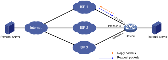
As is shown in Figure 1, when the external server sends a request to the internal server, the packet travels through ISP 1 to Interface A on the device. The last hop holding feature on the device ensures that the reply packet follows the same route as the request packet back to ISP 1. If last hop holding is disabled, the reply packet might be sent out of Interface B or Interface C to the external network.
Figure 1 Last hop holding application
Restrictions and guidelines
This feature is based on fast forwarding entries. If the MAC address of a last hop changes, this feature can function correctly only after the fast forwarding entry is updated for the MAC address.
This feature is not applicable to an MPLS network.
Procedure
1. Enter system view.
system-view
2. Enter Layer 3 Ethernet interface view or subinterface view.
¡ Enter Layer 3 Ethernet interface view.
interface interface-type interface-number
¡ Enter Layer 3 Ethernet subinterface view.
interface interface-type interface-number.subnumber
3. Enable last hop holding.
ip last-hop hold
By default, last hop holding is disabled.
Display and maintenance commands for FIB table
Execute display commands in any view.
|
Task |
Command |
|
Display FIB entries. |
display fib [ topology topology-name | vpn-instance vpn-instance-name ] [ ip-address [ mask | mask-length ] ] |
Configuring load sharing
About load sharing
If a routing protocol finds multiple equal-cost best routes to the same destination, the device forwards packets over the equal-cost routes to implement load sharing.
Configuring load sharing mode
About load sharing mode
In the per-flow load sharing mode, the device forwards flows over equal-cost routes. Packets of one flow travel along the same routes. You can configure the device to identify a flow based on the following criteria: source IP address, destination IP address, source port number, destination port number, IP protocol number, and ingress port.
In a complex network, when the criteria cannot distinguish flows, you can use the algorithm keyword to specify an algorithm to identify flows.
In the per-packet load sharing mode, the device forwards packets over equal-cost routes.
Procedure
1. Enter system view.
system-view
2. Configure load sharing.
In standalone mode:
ip load-sharing mode { per-flow [ dest-ip | dest-port | ip-pro | src-ip | src-port ] * | per-packet } global
ip load-sharing mode { per-flow [ dest-ip | dest-port | ip-pro | src-ip | src-port ] * | per-packet } { global | slot slot-number }
By default, the device performs per-flow load sharing.
Enabling IPv4 bandwidth-based load sharing
About IPv4 bandwidth-based load sharing
This feature load shares flow traffic among multiple output interfaces based on their load percentages. The device calculates the load percentage for each output interface in terms of the interface expected bandwidth.
Devices that run load sharing protocols, such as Locator/ID Separation Protocol (LISP), implement load sharing based on the ratios defined by these protocols.
Procedure
1. Enter system view.
system-view
2. Enable IPv4 bandwidth-based load sharing.
bandwidth-based-sharing
By default, the IPv4 bandwidth-based load sharing is disabled.
3. (Optional.) Configure the expected bandwidth of the interface.
a. Enter interface view.
interface interface-type interface-number
b. Configure the expected bandwidth of the interface.
bandwidth bandwidth
By default, the expected bandwidth is the physical bandwidth of the interface.