- Table of Contents
- Related Documents
-
| Title | Size | Download |
|---|---|---|
| 09-Frame Relay configuration | 235.33 KB |
Frame Relay network components
Restrictions and guidelines: Frame Relay configuration
Configuring DTE-side Frame Relay
Configuring DCE-side Frame Relay
Configuring basic DTE-side Frame Relay
Configuring basic DCE-side Frame Relay
Configuring local Frame Relay virtual circuits
Configuring Frame Relay address mapping
About Frame Relay address mapping methods
Configuring static address-to-DLCI mappings
Configuring dynamic IPv4 address mapping
Configuring dynamic IPv6 address mapping
Configuring Frame Relay subinterfaces
Configuring Frame Relay IPHC on an interface
Configuring Frame Relay IPHC on a virtual circuit
Configuring Frame Relay STAC compression on a virtual circuit
Configuring Frame Relay FRF.12 fragmentation on an interface
Enabling SNMP notifications for Frame Relay
Display and maintenance commands for Frame Relay
Frame Relay configuration examples
Example: Interconnecting LANs through a dedicated line
The physical layer is already up, but the link layer protocol is down
The link layer protocol is up, but the peer cannot be pinged
Configuring Multilink Frame Relay
Restoring the default settings for an MFR interface
Configuring an MFR bundle link
Display and maintenance commands for MFR
Configuring Frame Relay
This feature is supported only on the following modules:
· CE3.
· CPOS.
· CT3.
· E1.
· E1-F.
· POS.
· SAE.
· T1.
· T1-F.
This feature is not supported on the following routers:
· MSR810, MSR810-W, MSR810-W-DB, MSR810-LM, MSR810-W-LM, MSR810-10-PoE, MSR810-LM-HK, MSR810-W-LM-HK, MSR810-LMS-EA.
· MSR810-LMS, MSR810-LUS.
About Frame Relay
Frame Relay protocol
The Frame Relay protocol uses statistical multiplexing technology and can establish multiple virtual circuits over a single physical cable to fully utilize network bandwidth. Frame Relay uses data link connection identifiers (DLCIs) to identify virtual circuits. Frame Relay uses the Local Management Interface (LMI) protocol to maintain the status of each virtual circuit.
Frame Relay network components
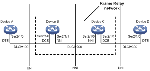
As shown in Figure 1:
· A Frame Relay network provides data communications between user devices such as routers and hosts. The user devices are also called data terminal equipment (DTE).
· The devices that provide access to the Frame Relay network for DTEs are called data circuit-terminating equipment (DCE).
Frame Relay interfaces include the following types:
· User-to-network interface (UNI)—A DCE is connected to a DTE through UNI interfaces. UNI interfaces include the following types:
? DTE interface—The UNI interface on the DTE side.
? DCE interface—The UNI interface on the DCE side.
· Network-to-network interface (NNI)—A DCE is connected to a Frame Relay switch in the Frame Relay network through an NNI interface. The switches in the Frame Relay network are interconnected with NNI interfaces.
A DTE interface can connect only to a DCE interface, and an NNI interface can connect only to an NNI interface. On a Frame Relay switch, the Frame Relay interface type must be NNI or DCE.
As shown in Figure 1:
· Device B and Device C form a simple Frame Relay network.
· DTE devices Device A and Device D are attached to the network.
The interface type DTE or DCE is identified only for the UNI interfaces. A virtual circuit between two DTE devices can be assigned different DLCIs on different segments.
Virtual circuit
Virtual circuits are logical connections established between two devices. Depending on how they are established, virtual circuits include the following types:
· Permanent virtual circuit (PVC)—A PVC is manually configured or dynamically learned through the LMI negotiation. The availability of a PVC must be detected before the PVC can be used.
· Switched virtual circuit (SVC)—An SVC is dynamically established between two devices through calls. The network provides data transmission services on established SVCs. The terminal users can terminate an SVC through clearing the call.
Unlike SVCs, PVCs rarely break or disconnect. PVCs are used more than SVCs.
On a DTE device, the state of a PVC is determined by the DCE device. On a DCE device, the state of a PVC depends on the way that the DCE device is connected to the DTE device.
· When the DCE device is directly connected to the DTE device, they use LMI to negotiate the state of a PVC.
· When the DCE device is connected to the DTE device through a Frame Relay network, the state of a PVC is determined by the LMI negotiation result and the virtual circuit state in the Frame Relay network.
DLCI
A DLCI uniquely identifies a virtual circuit on a physical link and has local significance only for that link. A DLCI can be used on different physical ports to address different virtual circuits. A virtual circuit between two DTE devices can be addressed with different DLCIs at the two ends, as shown in Figure 1.
Because the virtual circuits in a Frame Relay network are connection oriented, each DLCI on a physical port is destined for a different peer device. DLCIs are the Frame Relay addresses of peer devices.
The maximum number of PVCs that can be created on a Frame Relay interface is 1024. The user configurable DLCIs for the PVCs are in the range 16 to 1007. Other DLCIs are reserved. For example, DLCI 0 and DLCI 1023 are reserved for the LMI protocol to transfer control messages.
Frame Relay address mapping
Frame Relay address mapping associates the protocol address of a peer device with a Frame Relay address (local DLCI). Then, the upper-layer protocol, for example, IP, can locate the peer device.
For example, an IPv4 or IPv6 packet is transmitted across a Frame Relay network as follows:
1. When a DTE device receives an IPv4 or IPv6 packet, the DTE device looks up the IP routing table for the outgoing interface and next-hop address.
2. When the outgoing interface is enabled with Frame Relay encapsulation, the device looks up the next-hop address in the address-to-DLCI mappings for the DLCI.
3. The packet is transmitted over the virtual circuit identified by the DLCI.
The address-to-DLCI mappings include the following types:
· Static—Manually created.
· Dynamic—Created through InARP or Inverse Neighbor Discovery (IND).
Frame Relay uses InARP to create an address-to-DLCI mapping through the following process:
1. InARP sends an InARP request to the peer end through a virtual circuit at the InARP request interval during an InARP learning process when the following conditions exist:
? A new virtual circuit is established.
? The local interface is configured with an IPv4 address.
The InARP request carries the local IPv4 address. By default, the InARP request interval during an InARP learning process (the detection timer) is 60 seconds.
2. When the peer device receives the InARP request, the peer device obtains the local IPv4 address and creates an address-to-DLCI mapping. At the same time, the peer device responds with an InARP reply carrying its IPv4 address.
3. When the local device receives the InARP reply, it creates an address-to-DLCI mapping.
4. After the local device creates the address-to-DLCI mapping, the local device modifies the InARP request interval to 12 minutes (the aging timer).
The aging timer is fixed. When the aging timer expires, the local device continues to send InARP requests.
5. The local device sets the aging timer value to the detection interval when the following conditions exist:
? The aging timer expires.
? The local device has not received any InARP replies.
6. When the local device has not received any InARP replies within three detection intervals, the learned dynamic address-to-DLCI mapping is deleted.
When the local device has not received InARP replies within a detection interval, the local device continues to send InARP requests. The local device stops sending InARP packets until the local interface is not configured with an IPv4 address or the local PVC is inactive.
IND creates IPv6 address-to-DLCI mappings in a way similar to InARP.
LMI protocol
Frame Relay uses the LMI protocol to manage PVCs, including the following operations:
· Notify the addition of a PVC.
· Detect the deletion of a PVC.
· Monitor PVC status changes.
· Verify link integrity.
The system supports the following LMI standards:
· ITU-T Q.933 Annex A.
· ANSI T1.617 Annex D.
· Nonstandard LMI (compatible with other vendors).
To communicate properly, the DTE and the DCE must use the same type of LMI.
LMI messages
LMI messages include the following types:
· Status enquiry message—A DTE sends status enquiry messages regularly to a DCE to request the status of individual PVCs or verify the link integrity.
· Status message—When a DCE receiving a status enquiry message, the DCE responds with a status message. The status message is used to transmit the PVC status or verify the link integrity.
Status enquiry messages and status messages include the following types:
· Full status—Verifies the link integrity and transmits the PVC status.
· Link integrity verification (LIV)—Verifies the link integrity.
LMI negotiation parameters
Table 1 lists the parameters ITU-T Q.933 Annex A uses for message exchange. You can configure these parameters to optimize device performance.
Table 1 LMI negotiation parameters
|
Device role |
Timer/counter |
Value range |
Default value |
Description |
|
DTE |
Full status polling counter (N391) |
1 to 255 |
6 |
Sets the ratio of link integrity request messages sent to full status enquiry messages sent. The ratio is (N391-1):1. |
|
Error threshold counter (N392) |
1 to 10 |
3 |
Sets the number of errors required for LMI to declare a link dead, within the event count specified by N393. |
|
|
Monitored events counter (N393) |
1 to 10 |
4 |
Sets the monitored event count. If the number of errors within the N393 status enquiry messages reaches N392, a DTE considers that the error threshold is reached. |
|
|
Keepalive (link integrity verification polling) timer (T391) |
0 to 32767 0 means LMI disabled. |
10 |
Sets the interval (in seconds) at which a DTE sends a status enquiry message. An error is recorded if the DTE has not received any replies when the timer expires. |
|
|
DCE |
Error threshold counter (N392) |
1 to 10 |
3 |
Sets the number of errors required for LMI to declare a link dead, within the event count specified by N393. |
|
Monitored events count (N393) |
1 to 10 |
4 |
Sets the monitored event count. If the number of errors within the N393 status enquiry messages reaches N392, a DCE considers that the error threshold is reached. |
|
|
Keepalive (polling verification) timer (T392) |
5 to 30 |
15 |
Sets the interval (in seconds) for receiving a status enquiry message. If a DCE has not received any status enquiry messages when the timer expires, an error is recorded. |
How LMI works
LMI works in the following process:
1. When a DTE physically goes up, it sends a full status enquiry message to a DCE to request the virtual circuit status. At the same time, the T391 timer and the V391 counter start. The T391 timer specifies the polling interval at which the DTE sends status enquiry messages.
? When V391<N391, the DTE sends a link integrity verification message and requests only the link integrity.
? When V391=N391, the following events occur:
- V391 is reset to 0.
- The DTE sends a full status enquiry message to request not only the link integrity but also the status of all PVCs.
2. When the DCE receives a request, the DCE sends a status message that carries the status requested by the DTE. At the same time, the DCE starts the T392 timer and waits for the next status enquiry message. If the DCE has not received status enquiry messages when the T392 timer expires, the DCE records the error and increases the error count by one. If the number of errors exceeds N392 among N393 events, the DCE considers the physical link and all virtual circuits unavailable and will not use them to forward packets.
3. When the DTE receives a reply, the DTE updates the link status and PVC status. If the DTE has not received status messages when the T391 timer expires, the DTE records the error and increases the error count by one. If the number of errors exceeds N392 among N393 events, the DTE considers that the physical link and all virtual circuits unavailable and will not use them to forward packets.
Application scenarios
With Frame Relay, you can construct a public or private network as shown in Figure 2 and construct direct connections between data devices as shown in Figure 3.
Figure 2 Interconnecting LANs through a Frame Relay network
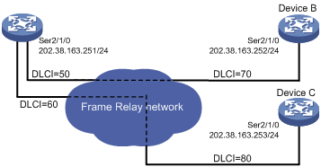
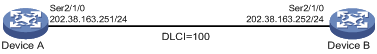
Figure 3 Interconnecting LANs through a dedicated line
Restrictions and guidelines: Frame Relay configuration
When you configure Frame Relay, follow these restrictions and guidelines:
· The following interfaces support Frame Relay:
? Synchronous serial interfaces, including synchronous serial interfaces derived from other interfaces.
? POS interfaces.
? POS channels.
· NNI interfaces are both DTE interfaces and DCE interfaces. You can configure an NNI interface in the same way a DCE or DTE interface is configured. An NNI interface cannot learn DLCIs. You must manually configure DLCIs at both ends.
· If one endpoint of a link is an NNI interface, the peer endpoint must also be an NNI interface.
Frame Relay tasks at a glance
Configuring DTE-side Frame Relay
To configure DTE-side Frame Relay, perform the following tasks:
1. Configuring basic DTE-side Frame Relay
2. Configuring local Frame Relay virtual circuits
3. Configuring Frame Relay address mapping
4. (Optional.) Configuring Frame Relay subinterfaces
5. (Optional.) Configure Frame Relay compression
? Configuring Frame Relay IPHC
? Configuring Frame Relay STAC compression on a virtual circuit
6. (Optional.) Configuring Frame Relay FRF.12 fragmentation on an interface
7. (Optional.) Enabling SNMP notifications for Frame Relay
Configuring DCE-side Frame Relay
To configure DCE-side Frame Relay, perform the following tasks:
1. Configuring basic DCE-side Frame Relay
2. Configuring local Frame Relay virtual circuits
3. Configuring Frame Relay address mapping
4. (Optional.) Configuring Frame Relay subinterfaces
5. (Optional.) Configure Frame Relay compression
? Configuring Frame Relay IPHC
? Configuring Frame Relay STAC compression on a virtual circuit
? (Optional.) Configuring Frame Relay FRF.12 fragmentation on an interface
6. (Optional.) Enabling SNMP notifications for Frame Relay
Configuring basic DTE-side Frame Relay
1. Enter system view.
system-view
2. Enter the view of the interface connecting to the Frame Relay network.
interface interface-type interface-number
3. Enable Frame Relay encapsulation on the interface.
link-protocol fr
By default, PPP encapsulation is enabled on interfaces except Ethernet interfaces and VLAN interfaces.
4. (Optional.) Configure the encapsulation type for the Frame Relay interface.
fr encapsulation { ietf | nonstandard }
The default setting is IETF.
5. (Optional.) Set the Frame Relay interface type to DTE.
fr interface-type dte
The default setting is DTE.
6. (Optional.) Configure the Frame Relay LMI protocol type.
fr lmi type { ansi | nonstandard | q933a }
The default setting is q933a.
7. (Optional.) Set Frame Relay link status parameters.
? Set the DTE-side N391 counter.
fr lmi n391dte n391-value
The default setting is 6.
? Set the DTE-side N392 counter.
fr lmi n392dte n392-value
The default setting is 3.
? Set the DTE-side N393 counter.
fr lmi n393dte n393-value
The default setting is 4.
? Set the DTE-side T391 timer.
timer-hold seconds
The default setting is 10 seconds.
Configuring basic DCE-side Frame Relay
1. Enter system view.
system-view
2. Enter the view of the interface connecting to the Frame Relay network.
interface interface-type interface-number
3. Enable Frame Relay encapsulation on the interface.
link-protocol fr
By default, PPP encapsulation is enabled on interfaces except Ethernet interfaces, ATM interfaces, and VLAN interfaces.
4. (Optional.) Configure the encapsulation type for the Frame Relay interface.
fr encapsulation { ietf | nonstandard }
The default setting is IETF.
5. (Optional.) Set the Frame Relay interface type to DCE or NNI.
fr interface-type { dce | nni }
The default setting is DTE.
An NNI interface connects two DCE devices. A DCE interface connects a DCE device to a DTE device.
6. (Optional.) Configure the Frame Relay LMI protocol type.
fr lmi type { ansi | nonstandard | q933a }
The default setting is q933a.
7. (Optional.) Set Frame Relay link status parameters.
? Set the DCE-side N392 counter.
fr lmi n392dce n392-value
The default setting is 3.
? Set the DCE-side N393 counter.
fr lmi n393dce n393-value
The default setting is 4.
? Set the DCE-side T392 timer.
fr lmi t392dce t392-value
The default setting is 15 seconds.
Configuring local Frame Relay virtual circuits
About local Frame Relay virtual circuits
The available methods of creating virtual circuits vary by interface type.
· On a DCE or NNI main interface or subinterface, the virtual circuit must be manually created.
· On a DTE main interface, virtual circuits can be automatically created through negotiation with the peer interface or manually created.
· On a DTE subinterface, the virtual circuit must be manually created.
This section describes how to manually create virtual circuits.
Restrictions and guidelines
When you configure local Frame Relay virtual circuits, follow these restrictions and guidelines:
· When manually creating virtual circuits on a DTE interface, make sure their DLCIs are the same as those used on the DCE.
· If the DLCI of a virtual circuit changes on a DCE interface, perform one of the following tasks for the DTE to quickly relearn the correct address-to-DLCI mappings. Before performing either of the following tasks, make sure no services will be interrupted.
? Reset both the DCE and DTE interfaces.
? Execute the reset inarp command on both ends.
· The DLCI of a virtual circuit must be unique on a main interface and all its subinterfaces.
Procedure
1. Enter system view.
system-view
2. Enter interface view.
interface interface-type interface-number
The interface can be a main interface or subinterface.
3. Create a virtual circuit on the interface.
fr dlci dlci-number
4. (Optional.) Configure the encapsulation type for the virtual circuit.
fr encapsulation { ietf | nonstandard }
By default, a virtual circuit uses the encapsulation type configured on its interface.
5. (Optional.) Allow broadcast packets on the virtual circuit.
broadcast
By default, broadcast packets are forbidden on static virtual circuits and allowed on dynamic virtual circuits.
When a virtual circuit allows broadcast packets, the broadcast or multicast packets on the Frame Relay interface of the virtual circuit are also transmitted on the virtual circuit.
Configuring Frame Relay address mapping
About Frame Relay address mapping methods
Use either of the following methods to configure Frame Relay address mapping:
· Static—Use this method when the network topology is stable and no new users are expected for a specific period of time. Because static address-to-DLCI mappings do not change, the network connections are stable, and attacks from unknown users are avoided.
· Dynamic—Use this method in complex networks. Make sure the peer devices also support InARP or IND.
Configuring static address-to-DLCI mappings
1. Enter system view.
system-view
2. Enter interface view.
interface interface-type interface-number
The interface can be a main interface or P2MP subinterface.
3. Create a static Frame Relay address-to-DLCI mapping.
IPv4:
fr map ip { ip-address | default } dlci-number
IPv6:
fr map ipv6 { ipv6-address | default } dlci-number
As a best practice, if you configure an IPv6 address-to-DLCI mapping, also configure an address-to-DLCI mapping for the link-local address of the peer. This ensures that packets with the link-local address as the destination address can be forwarded.
Configuring dynamic IPv4 address mapping
1. Enter system view.
system-view
2. Enter interface view.
interface interface-type interface-number
3. Enable Frame Relay InARP for dynamic address mapping.
fr inarp ip [ dlci-number ]
By default, Frame Relay InARP is enabled for dynamic address mapping.
4. Set the InARP request interval during the InARP learning process.
fr inarp interval interval
The default setting is 60 seconds.
Configuring dynamic IPv6 address mapping
1. Enter system view.
system-view
2. Enter interface view.
interface interface-type interface-number
3. Enable Frame Relay IND for dynamic address mapping.
fr ipv6 ind [ dlci-number ]
By default, Frame Relay IND is disabled for dynamic address mapping.
4. Set the IND request interval during the IND learning process.
ipv6 ind holdtime seconds
The default setting is 30 seconds.
5. Set the interval between continuous IND requests.
ipv6 ind solicitation retrans-timer seconds
The default setting is 1 second.
Configuring Frame Relay subinterfaces
About Frame Relay subinterfaces
Frame Relay provides main interfaces and subinterfaces. A subinterface is a logical interface. It can be configured with protocol addresses and virtual circuits. One physical interface can include multiple subinterfaces. The subinterfaces and main interfaces can all be configured with virtual circuits to connect to peer devices.
Frame Relay subinterfaces include the following types:
· Point-to-point (P2P) subinterface—A P2P subinterface connects to a single peer device.
· Point-to-multipoint (P2MP) subinterface—A P2MP subinterface connects to multiple peer devices. A P2MP subinterface can be configured with multiple virtual circuits. An address-to-DLCI mapping can be configured for each virtual circuit and its connected peer network address. Address-to-DLCI mappings can be dynamically configured through InARP or manually configured.
The methods of configuring a virtual circuit and address-to-DLCI mapping for P2P subinterfaces and P2MP subinterfaces have the following differences:
· P2P subinterface—Because a P2P subinterface has only one peer address, the peer address is determined when a virtual circuit is configured for the subinterface. You cannot configure static address-to-DLCI mappings or enable InARP for a P2P subinterface.
· P2MP subinterface—For a P2MP subinterface, a peer address can be mapped to the local DLCI through static address-to-DLCI mappings or InARP. To enable InARP for dynamic address mapping on a P2MP subinterface, you only need to enable InARP on the main interface. If static address-to-DLCI mappings are needed, you must configure a static address-to-DLCI mapping for each virtual circuit.
Procedure
1. Enter system view.
system-view
2. Create a subinterface and enter subinterface view.
interface interface-type interface-number.subnumber [ p2mp | p2p ]
If you do not specify a subinterface type when you create a Frame Relay interface, a P2MP subinterface is created.
3. Configure a virtual circuit on the Frame Relay subinterface.
See "Configuring local Frame Relay virtual circuits."
On a Frame Relay subinterface, virtual circuits must be created manually.
4. Configure address mapping.
See "Configuring Frame Relay address mapping."
This task is available on P2MP subinterfaces.
Configuring Frame Relay IPHC
About Frame Relay IPHC
IP header compression (IPHC) reduces the amount of bandwidth consumed by packet headers. It is typically used for voice communication on low-speed links.
IPHC includes the following types:
· RTP header compression—Compresses the IP/UDP/RTP header (40 bytes in total) in packets.
· TCP header compression—Compresses the TCP/IP header (40 bytes in total) in packets.
For the duration of a connection, some fields in the RTP/UDP/IP or TCP/IP header do not change, and other fields change in a predictable way. The IPHC compressor and decompressor maintain the fields that do not change and the fields that change in a predictable way. The compressor only needs to transmit the fields of a header that change.
Restrictions and guidelines
When you configure Frame Relay IPHC, follow these restrictions and guidelines:
· Frame Relay IPHC and STAC compression are mutually exclusive.
· To make IPHC take effect on a link, you must enable Frame Relay IPHC on both ends of the link.
· You can configure Frame Relay IPHC on either an interface or a virtual circuit. The settings on an interface take effect on all virtual circuits of the interface. The settings on a virtual circuit take effect only on the virtual circuit. When the interface settings are different from the virtual circuit settings, the virtual circuit settings take effect.
· When the encapsulation type is IETF, IPHC negotiation is triggered after you enable IPHC. IPHC takes effect only when IPHC negotiation succeeds. When the encapsulation type is nonstandard, IPHC takes effect without negotiation. In this case, the encapsulation type must be nonstandard on both ends of the link.
· Compression does not stop after you disable IPHC on an interface or virtual circuit. To stop compression, you must also execute the shutdown/undo shutdown command sequence on the interface or virtual circuit.
· You can set the maximum number of RTP/TCP header-compression connections only after you enable IPHC on an interface or virtual circuit. The configuration takes effect after you execute the shutdown/undo shutdown command sequence on the interface or virtual circuit. After you disable IPHC, the configuration is deleted.
Configuring Frame Relay IPHC on an interface
1. Enter system view.
system-view
2. Enter interface view.
interface interface-type interface-number
3. Enable Frame Relay IPHC.
fr compression iphc enable [ nonstandard ]
By default, Frame Relay IPHC is disabled.
If you specify the nonstandard keyword, only RTP header compression is supported, and TCP header compression is not supported.
4. Set the maximum number of RTP header-compression connections allowed.
fr compression iphc rtp-connections
The default setting is 16.
5. Set the maximum number of TCP header-compression connections allowed.
fr compression iphc tcp-connections
The default setting is 16.
Configuring Frame Relay IPHC on a virtual circuit
1. Enter system view.
system-view
2. Enter interface view.
interface interface-type interface-number
The interface can be a main interface or a subinterface.
3. Create a virtual circuit on the interface.
fr dlci dlci-number
4. Enable Frame Relay IPHC.
fr compression iphc enable [ nonstandard ]
By default, Frame Relay IPHC is disabled.
If you specify the nonstandard keyword, only RTP header compression is supported, and TCP header compression is not supported.
5. Set the maximum number of RTP header-compression connections allowed.
fr compression iphc rtp-connections
The default setting is 16.
6. Set the maximum number of TCP header-compression connections allowed.
fr compression iphc tcp-connections
The default setting is 16.
Configuring Frame Relay STAC compression on a virtual circuit
About Frame Relay STAC compression
STAC compression is a payload compression method that applies to Frame Relay packets, InARP packets, and IND packets. STAC compression cannot compress LMI messages.
The two ends of a PVC negotiate the PVC state by using STAC control messages after STAC compression is enabled. The PVC state negotiation succeeds only when STAC compression is enabled on both ends of the PVC. After PVC state negotiation succeeds, both ends can transmit compressed packets on the PVC. If one end does not receive response messages from the peer after sending 10 control messages, it stops sending control messages. The PVC state negotiation fails.
Restrictions and guidelines
When you configure Frame Relay STAC compression, follow these restrictions and guidelines:
· Frame Relay IPHC and STAC compression are mutually exclusive.
· To make STAC compression take effect on a PVC, you must enable Frame Relay STAC compression on both ends of the PVC.
· STAC compression works only when the encapsulation type is IETF on both ends of a PVC. If the encapsulation type is not IETF when you enable STAC compression, the system automatically changes the encapsulation type to IETF.
Procedure
1. Enter system view.
system-view
2. Enter interface view.
interface interface-type interface-number
The interface can be a main interface or a subinterface.
3. Create a virtual circuit on the interface.
fr dlci dlci-number
4. Enable STAC compression on the virtual circuit.
fr compression stac enable
By default, STAC compression is disabled on a virtual circuit.
Configuring Frame Relay FRF.12 fragmentation on an interface
About Frame Relay FRF.12 fragmentation
FRF.12 fragmentation divides large packets into smaller fragments at the sending end and reassembles the fragments at the receiving end. This process helps reduce the transmission delay for voice traffic when data traffic and voice traffic are transmitted together on low-speed links. FRF.12 fragmentation takes effect only on outgoing packets.
FRF.12 fragmentation includes the following types:
· NNI&UNI.
· End-to-end.
Only end-to-end FRF.12 fragmentation is supported in the current software version.
Restrictions and guidelines
When you configure Frame Relay FRF.12 fragmentation, follow these restrictions and guidelines:
· FRF.12 fragmentation and Frame Relay traffic shaping are mutually exclusive on an interface. For more information about Frame Relay traffic shaping, see ACL and QoS Configuration Guide.
· An MFR interface does not support FRF.12 fragmentation.
? If both ends of a link are MFR interfaces, FRF.12 fragmentation does not take effect on either end.
? If one end of a link is a Frame Relay interface, FRF.12 fragmentation takes effect on the Frame Relay interface.
Procedure
1. Enter system view.
system-view
2. Enter interface view.
interface interface-type interface-number
3. Enable FRF.12 fragmentation on the interface.
fr fragment enable
By default, FRF.12 fragmentation is disabled on an interface.
4. (Optional.) Set the fragment size allowed on the interface.
fr fragment size
The default setting is 45 bytes.
Enabling SNMP notifications for Frame Relay
About enabling SNMP notifications for Frame Relay
After you enable SNMP notifications for Frame Relay, Frame Relay generates notifications for important events and sends the notifications to the SNMP module. For more information about SNMP notifications, see Network Management and Monitoring Configuration Guide.
Procedure
1. Enter system view.
system-view
2. Enable SNMP notifications for Frame Relay.
snmp-agent trap enable fr
By default, SNMP notifications are disabled for Frame Relay.
Display and maintenance commands for Frame Relay
Execute the display commands in any view and the reset commands in user view.
|
Task |
Command |
|
Display statistics for Frame Relay IPHC. |
display fr compression iphc { rtp | tcp } [ interface interface-type interface-number [ dlci dlci-number ] ] |
|
Display statistics for Frame Relay STAC compression. |
display fr compression stac [ interface interface-type interface-number [ dlci dlci-number ] ] |
|
Display statistics for Frame Relay FRF.12 fragmentation. |
display fr fragment [ interface interface-type interface-number [ dlci dlci-number ] ] |
|
Display statistics for Frame Relay InARP packets. |
display fr inarp [ interface interface-type interface-number ] |
|
Display Frame Relay IPv6 address mapping of interfaces. |
display fr ipv6 map [ static | dynamic ] [ interface interface-type interface-number [ dlci dlci-number ] ] |
|
Display the LMI information of interfaces. |
display fr lmi [ interface interface-type interface-number ] |
|
Display Frame Relay IPv4 address mapping of interfaces. |
display fr map [ interface interface-type interface-number ] |
|
Display information on Frame Relay PVCs and statistics about data sent and received on them. |
display fr pvc [ interface interface-type interface-number ] [ dlci dlci-number ] |
|
Clear statistics for Frame Relay IPHC. |
reset fr compression iphc { rtp | tcp } [ interface interface-type interface-number [ dlci dlci-number ] ] |
|
Clear the address-to-DLCI mappings established by InARP. |
reset fr inarp [ interface interface-type interface-number [ dlci dlci-number ] ] |
|
Clear the address-to-DLCI mappings established by IND. |
reset fr ipv6 ind [ interface interface-type interface-number [ dlci dlci-number ] ] |
|
Clear statistics of PVCs. |
reset fr pvc [ interface interface-type interface-number [ dlci dlci-number ] ] |
Frame Relay configuration examples
Example: Interconnecting LANs through a dedicated line
Network configuration
As shown in Figure 4, configure Frame Relay so that Router A and Router B can communicate.

Procedure
(Method 1) Using main interfaces:
1. Configure Router A:
# Assign an IP address to Serial 2/1/0.
<RouterA> system-view
[RouterA] interface serial 2/1/0
[RouterA-Serial2/1/0] ip address 202.38.163.251 255.255.255.0
# Enable Frame Relay encapsulation on the interface.
[RouterA-Serial2/1/0] link-protocol fr
# Set the type of the interface to DCE.
[RouterA-Serial2/1/0] fr interface-type dce
# Configure a local virtual circuit.
[RouterA-Serial2/1/0] fr dlci 100
2. Configure Router B:
# Assign an IP address to Serial 2/1/0.
<RouterB> system-view
[RouterB] interface serial 2/1/0
[RouterB-Serial2/1/0] ip address 202.38.163.252 255.255.255.0
# Enable Frame Relay encapsulation on the interface.
[RouterB-Serial2/1/0] link-protocol fr
# Set the type of the interface to DTE.
[RouterB-Serial2/1/0] fr interface-type dte
[RouterB-Serial2/1/0] quit
(Method 2) Using subinterfaces:
1. Configure Router A:
# Enable Frame Relay encapsulation on Serial 2/1/0.
<RouterA> system-view
[RouterA] interface serial 2/1/0
[RouterA-Serial2/1/0] link-protocol fr
# Set the type of Serial 2/1/0 to DCE.
[RouterA-Serial2/1/0] fr interface-type dce
[RouterA-Serial2/1/0] quit
# Create a subinterface named Serial 2/1/0.1.
[RouterA] interface serial 2/1/0.1 p2p
# Configure the IP address and create a virtual circuit for Serial 2/1/0.1.
[RouterA-Serial2/1/0.1] ip address 202.38.163.251 255.255.255.0
[RouterA-Serial2/1/0.1] fr dlci 100
2. Configure Router B:
# Enable Frame Relay encapsulation on Serial 2/1/0.
<RouterB> system-view
[RouterB] interface serial 2/1/0
[RouterB-Serial2/1/0] link-protocol fr
# Set the type of Serial 2/1/0 to DTE.
[RouterB-Serial2/1/0] fr interface-type dte
[RouterB-Serial2/1/0] quit
# Create a subinterface named Serial 2/1/0.1.
[RouterB] interface serial 2/1/0.1 p2p
# Configure the IP address and create a virtual circuit for Serial 2/1/0.1.
[RouterB-Serial2/1/0.1] ip address 202.38.163.252 255.255.255.0
[RouterB-Serial2/1/0.1] fr dlci 100
[RouterB-Serial2/1/0.1] quit
Verifying the configuration
This section verifies the configuration used in method 1.
# On Router B, verify that the PVC is active.
[RouterB] display fr pvc
PVC information for interface Serial2/1/0 (DTE, physically up)
DLCI: 100 Type: Dynamic Interface: Serial2/1/0
Encapsulation: IETF Broadcast
Creation time: 2014/02/19 01:38:00 Status: Active
Input: 2 packets, 60 bytes, 0 dropped
Output: 2 packets, 60 bytes, 0 dropped
# Verify that Router A and Router B can ping each other.
[RouterB] ping 202.38.163.251
Ping 202.38.163.251 (202.38.163.251): 56 data bytes, press CTRL_C to break
56 bytes from 202.38.163.251: icmp_seq=0 ttl=255 time=76.007 ms
56 bytes from 202.38.163.251: icmp_seq=1 ttl=255 time=8.790 ms
56 bytes from 202.38.163.251: icmp_seq=2 ttl=255 time=1.630 ms
56 bytes from 202.38.163.251: icmp_seq=3 ttl=255 time=0.841 ms
56 bytes from 202.38.163.251: icmp_seq=4 ttl=255 time=1.012 ms
--- Ping statistics for 202.38.163.251 ---
5 packets transmitted, 5 packets received, 0.0% packet loss
round-trip min/avg/max/std-dev = 0.841/17.656/76.007/29.326 ms
Troubleshooting Frame Relay
The physical layer is down
Symptom
The physical layer is down.
Solution
To resolve this problem:
1. Verify that the physical line is working correctly.
2. Verify that the peer device is working correctly.
3. If the problem persists, contact H3C Support.
The physical layer is already up, but the link layer protocol is down
Symptom
The physical layer is already up, but the link layer protocol is down.
Solution
To resolve this problem:
1. Verify that Frame Relay is enabled on the peer devices.
2. Verify that one end is in DTE mode and the other end is in DCE mode if the two devices are directly connected.
3. Verify that both ends are using the same LMI protocol.
4. Execute the debugging lmi command to identify whether one status message is received for each status enquiry message. If not, examine the physical layer.
5. If the problem persists, contact H3C Support.
The link layer protocol is up, but the peer cannot be pinged
Symptom
The link layer protocol is up, but the peer cannot be pinged.
Solution
To resolve this problem:
1. Verify that the devices at both ends have configured correct address-to-DLCI mappings for the peer.
2. Verify that a route to the peer exists if the devices are not on the same subnet segment.
3. If the problem persists, contact H3C Support.
Configuring Multilink Frame Relay
About Multilink Frame Relay
Multilink Frame Relay (MFR) is a cost-effective bandwidth solution that is based on Frame Relay Forum Multilink Frame Relay UNI/NNI Implementation Agreement (FRF.16.1). This feature increases bandwidth by bundling multiple physical links into a logical link.
MFR uses the following concepts:
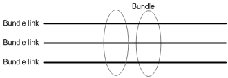
· Bundle—A virtual interface formed by combining multiple physical interfaces. A bundle corresponds to an MFR interface. A bundle is visible to the data link layer.
· Bundle link—Corresponds to a physical interface. A bundle contains and manages multiple bundle links, as shown in Figure 5. Bundle links are visible to the physical layer.
Figure 5 Bundle and bundle links
After a bundle is formed, its bundle links periodically send hello messages to maintain link status. If a bundle link fails to receive a hell acknowledgment after it resends hell messages for the specified maximum number of times, the bundle link is considered to be down at the link layer.
MFR interfaces support DTE and DCE interface types and QoS queuing mechanisms. Physical interfaces bundled into an MFR interface use the data link and network parameter settings of the MFR interface. Their original parameters settings do not work.
MFR tasks at a glance
To configure MFR, perform the following tasks:
2. Configuring an MFR bundle link
Configuring an MFR bundle
Configuring an MFR interface
1. Enter system view.
system-view
2. Create an MFR interface and enter MFR interface view.
interface mfr { interface-number | interface-number.subnumber [ p2mp | p2p ] }
Before creating an MFR subinterface, make sure the main MFR interface already exists.
3. (Optional.) Set a description for the MFR interface.
description text
By default, the description of an MFR interface is interface name Interface, for example, MFR4 Interface.
4. (Optional.) Set the MFR bundle identifier.
mfr bundle-name name
The default bundle identifier is MFR + frame relay bundle number, for example, MFR4.
You cannot set a bundle identifier in the MFR number format.
5. (Optional.) Enable MFR fragmentation.
mfr fragment enable
By default, MFR fragmentation is disabled.
6. (Optional.) Set the size of the MFR sliding window.
mfr window-size number
By default, the size of the MFR sliding window is the number of physical interfaces bundled by MFR.
7. (Optional.) Set maximum fragment size allowed for bundle links.
mfr fragment-size size
The default setting is 300 bytes.
8. (Optional.) Enable subinterface rate statistics collection for the MFR interface.
sub-interface rate-statistic
By default, this feature is disabled.
When this feature is enabled for an MFR interface, the system periodically refreshes subinterface rate statistics. You can use the display interface command to view the collected statistics.
This feature is resource intensive. When you use this feature, make sure you fully understand its impact on system performance.
9. (Optional.) Set the expected bandwidth for the MFR interface.
bandwidth bandwidth-value
By default, the expected bandwidth (in kbps) is the interface baud rate divided by 1000.
10. Bring up the MFR interface.
undo shutdown
By default, an MFR interface is up.
11. (Optional.) Configure other parameters for the MFR interface.
See "Configuring Frame Relay."
The fr interface-type and fr inarp commands can be used only on main MFR interfaces.
Restoring the default settings for an MFR interface
Restrictions and guidelines
The default command might interrupt ongoing network services. Make sure you are fully aware of the impact of this command when you execute it on a live network.
This command might fail to restore the default settings for some commands for reasons such as command dependencies or system restrictions. Use the display this command in interface view to identify these commands. Then use their undo forms or follow the command reference to restore their default settings. If your restoration attempt still fails, follow the error message instructions to resolve the problem.
Procedure
1. Enter MFR interface view.
interface mfr { interface-number | interface-number.subnumber [ p2mp | p2p ] }
2. Restore the default settings for an MFR interface.
default
Configuring an MFR bundle link
Restrictions and guidelines
· As a best practice to maximize bandwidth that can be used, bundle physical interfaces of the same speed in one bundle.
· Only synchronous serial interfaces and POS interfaces can be configured as bundle links.
Procedure
1. Enter system view.
system-view
2. Enter interface view.
interface interface-type interface-number
3. Enable MFR encapsulation on the interface.
link-protocol mfr
By default, synchronous serial interfaces and POS interfaces use PPP encapsulation.
4. Assign the interface to an MFR interface.
fr mfr interface-number
By default, an interface is not assigned to any MFR interfaces.
5. (Optional.) Set the MFR bundle link identifier.
mfr link-name name
By default, the name of the current interface is used.
6. (Optional.) Set the interval at which the MFR bundle link sends hello messages.
mfr timer hello seconds
The default setting is 10 seconds.
7. (Optional.) Set the time that the bundle link waits for a hello acknowledgment before resending the hello message.
mfr timer ack seconds
The default setting is 4 seconds.
8. (Optional.) Set the maximum number of times that the MFR bundle link can resend hello messages.
mfr retry retries
The default setting is 2.
Display and maintenance commands for MFR
Execute display commands in any view and reset commands in user view.
|
Task |
Command |
|
Display MFR interface information. |
display interface [ mfr [ interface-number ] ] [ brief [ description | down ] ] |
|
Display the configuration and statistics for MFR bundles and bundle links. |
display mfr [ interface interface-type interface-number | verbose ] |
|
Clear interfaces statistics. |
reset counters interface [ mfr [ interface-number | interface-number.subnumber ] ] |
MFR configuration examples
Example: Configuring MFR
Network configuration
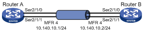
As shown in Figure 6, use MFR to bind the physical links between Router A and Router B into a logical link with higher bandwidth than each physical link.
Procedure
1. Configure Router A:
# Create an interface named MFR 4, and assign an IP address to the interface.
<RouterA> system-view
[RouterA] interface mfr 4
[RouterA-MFR4] ip address 10.140.10.1 255.255.255.0
# Set the type of the interface to DTE.
[RouterA-MFR4] fr interface-type dte
# Configure a static Frame Relay address-to-DLCI mapping for the interface.
[RouterA-MFR4] fr map ip 10.140.10.2 100
[RouterA-MFR4] quit
# Bind Serial 2/1/0 and Serial 2/1/1 to MFR 4.
[RouterA] interface serial 2/1/0
[RouterA-Serial2/1/0] link-protocol mfr
[RouterA-Serial2/1/0] fr mfr mfr4
[RouterA-Serial2/1/0] quit
[RouterA] interface serial 2/1/1
[RouterA-Serial2/1/1] link-protocol mfr
[RouterA-Serial2/1/1] fr mfr mfr4
[RouterA-Serial2/1/1] quit
2. Configure Router B:
# Create an interface named MFR 4, and assign an IP address to the interface.
<RouterB> system-view
[RouterB] interface mfr 4
[RouterB-MFR4] ip address 10.140.10.2 255.255.255.0
# Set the type of the interface to DCE.
[RouterB-MFR4] fr interface-type dce
# Create a virtual circuit for the interface.
[RouterB-MFR4] fr dlci 100
[RouterB-MFR4-fr-dlci-100] quit
# Configure a static Frame Relay address-to-DLCI mapping for the interface.
[RouterB-MFR4] fr map ip 10.140.10.1 100
[RouterB-MFR4] quit
# Bind Serial 2/1/0 and Serial 2/1/1 to MFR 4.
[RouterB] interface serial 2/1/0
[RouterB-Serial2/1/0] link-protocol mfr
[RouterB-Serial2/1/0] fr mfr mfr4
[RouterB-Serial2/1/0] quit
[RouterB] interface serial 2/1/1
[RouterB-Serial2/1/1] link-protocol mfr
[RouterB-Serial2/1/1] fr mfr mfr4
[RouterB-Serial2/1/1] quit
Verifying the configuration
# On Router A, verify that the PVC is active.
[RouterA] display fr pvc
PVC information for interface MFR4 (DTE, physically up)
DLCI: 100 Type: Static Interface: MFR4
Encapsulation: IETF
Creation time: 2014/08/18 06:38:00 Status: Active
Input: 0 packets, 0 bytes, 0 dropped
Output: 0 packets, 0 bytes, 0 dropped
# Verify that Router A and Router B can ping each other.
[RouterA] ping 10.140.10.2
Ping 10.140.10.2 (10.140.10.2): 56 data bytes, press CTRL_C to break
56 bytes from 10.140.10.2: icmp_seq=0 ttl=255 time=76.007 ms
56 bytes from 10.140.10.2: icmp_seq=1 ttl=255 time=8.790 ms
56 bytes from 10.140.10.2: icmp_seq=2 ttl=255 time=1.630 ms
56 bytes from 10.140.10.2: icmp_seq=3 ttl=255 time=0.841 ms
56 bytes from 10.140.10.2: icmp_seq=4 ttl=255 time=1.012 ms
--- Ping statistics for 10.140.10.2 ---
5 packets transmitted, 5 packets received, 0.0% packet loss
round-trip min/avg/max/std-dev = 0.841/17.656/76.007/29.326 ms