- Table of Contents
- Related Documents
-
| Title | Size | Download |
|---|---|---|
| 02-VM configuration | 823.61 KB |
ICT converged gateway architecture
Restrictions: Hardware compatibility with VMs
VM configuration tasks at a glance
Specifying a VLAN for a VF interface
Removing an SR-IOV NIC from a VM
Specifying a VLAN for a vTap interface
Allocating CPU cores to the VM plane
Binding vCPUs to physical CPUs
Configuring the VNC port of a VM
Display and maintenance commands for VMs
Configuring virtual machines
About virtual machines
The device can act as an ICT converged gateway. It integrates IT and CT based on X86 virtualization technologies and provides edge computing services.
ICT converged gateway architecture
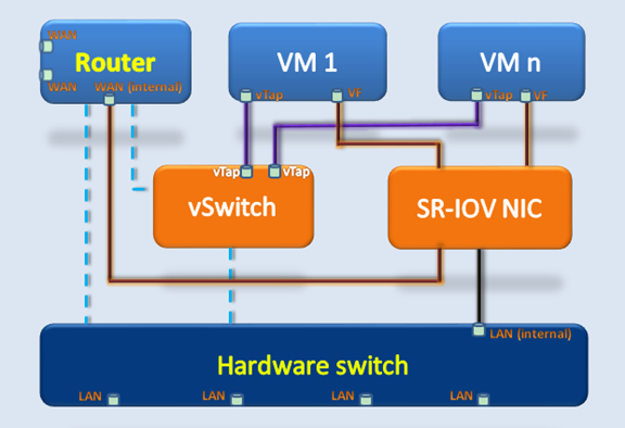
As shown in Figure 1, the virtualization service of an ICT converged gateway contains the following components:
· Virtual machines (VMs)—Virtual system similar to a physical host. You can install guest OSs and applications on VMs.
· Router—The routing system.
· WAN—WAN ports.
· WAN (internal)—An internal WAN interface connects to the SR-IOV NIC.
· LAN—LAN ports.
· LAN (internal)—An internal LAN interface connects to the SR-IOV NIC.
· Hardware switch—Hardware switching module.
· vSwitch—Software switching module.
· SR-IOV NIC—NIC that supports the single-root I/O virtualization (SR-IOV) technology. The SR-IOV technology is a hardware-based virtualization technology that allows VMs to directly access the hardware I/O components. The technology virtualizes a physical function (PF) into multiple virtual functions (VFs). Typically, a physical NIC is a PF. VMs use the VFs virtualized from the PF as their virtual NICs. A VF interface can have the same performance as a physical interface.
An SR-IOV NIC is the core component of the SR-IOV technology. The NIC passes through VF interfaces to VMs to use.
· VM network interfaces—Interfaces that VMs can use to connect to the network. An ICT converged gateway provides the following types of network interfaces for VM communication:
? vTap interfaces—Software-based network interfaces, which are virtualized by the vSwitch. A vTap interface is a low-speed interface.
? VF interfaces—Hardware-based network interfaces, which are provided by the SR-IOV NIC. A VF interface is a high-speed interface.
The vSwitch and SR-IOV NIC are reachable at Layer 2 and Layer 3. VMs can communicate with other entities at Layer 2 and Layer 3.
Figure 1 ICT converged gateway architecture
VM link modes
Accessing a VM is similar to accessing a host. However, the network connection of a VM is different than a host. An ICT converged gateway supports the following link modes for a VM to access the network.
vTap interface link mode
A VM accesses the network through a vTap interface. The access speed in this mode is slower than that in VF interface link mode. However, this mode supports low-version guest OSs.
The vTap interface of a VM is connected to the vSwitch. The vSwitch is a virtual switching unit, which can perform flexible Layer 2 traffic forwarding for virtual interfaces. In addition, the vSwitch is connected to the routing system and hardware switch for Layer 2 and Layer 3 communication.
VF interface link mode
A VM accesses the network through a VF interface. The access speed in this mode is faster than that in vTap interface link mode. However, the VM needs to install an SR-IOV NIC driver. Driver installation might fail on a low-version guest OS.
The hardware-based SR-IOV technology provides highly-reliable and scalable virtualization services. A VM can use a VF interface to directly access the SR-IOV NIC. A VF interface can have the same performance as a physical network interface.
The SR-IOV NIC is connected to the routing system and hardware switch for Layer 2 and Layer 3 communication.
Communication mechanisms
The ICT converged gateway provides the same functionality as a traditional router. The following information only describes the communication mechanisms related to VMs.
VM-to-VM traffic forwarding
Figure 2 illustrates the forwarding path for the traffic from a vTap interface on one VM to a vTap interface on another VM. The vSwitch is used to forward the traffic.
Figure 2 vTap-to-vTap traffic forwarding
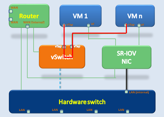
Figure 3 illustrates the forwarding path for the traffic from a vTap interface on one VM to a VF interface on another VM. The traffic is forwarded to the vSwitch and the vSwitch forwards the traffic to the hardware switch. Then, the hardware switch forwards the traffic to the destination VF interface through the SR-IOV NIC. The path of VF-to-vTap traffic forwarding is the reverse of the vTap-to-VF traffic forwarding path.
Figure 3 vTap-to-VF traffic forwarding
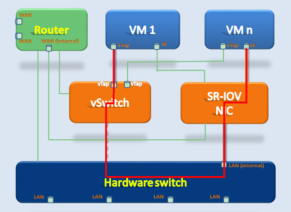
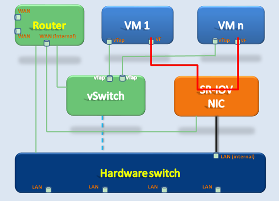
Figure 4 illustrates the forwarding path for the traffic from a VF interface on one VM to a VF interface on another VM. The SR-IOV NIC forwards the traffic.
Figure 4 VF-to-VF traffic forwarding
VM-to-WAN traffic forwarding
Figure 5 illustrates the forwarding path for the traffic from a vTap interface on a VM to a WAN port on the device. The vTap interface forwards the traffic to the vSwitch, and then the vSwitch forwards the traffic to the routing system. Finally, the routing system forwards the traffic to the WAN port.
Figure 5 vTap-to-WAN traffic forwarding
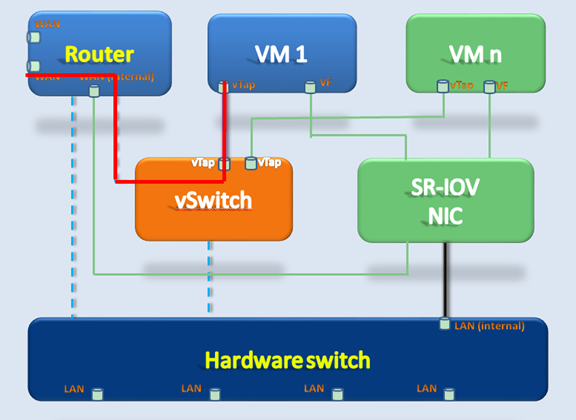
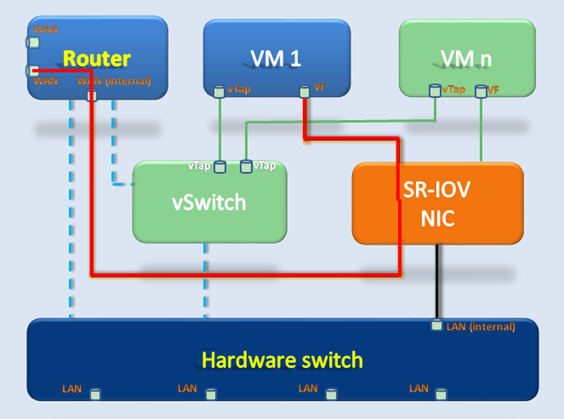
Figure 6 illustrates the forwarding path for the traffic from a VF interface on a VM to a WAN port on the device. The VF interface accesses the SR-IOV NIC, and then the SR-IOV NIC passes the traffic to the routing system. Finally, the routing system forwards the traffic to the WAN port.
Figure 6 VF-to-WAN traffic forwarding
VM-to-LAN traffic forwarding
Figure 7 illustrates the forwarding path for the traffic from a vTap interface on a VM to a LAN port on the device. The vTap interface forwards the traffic to the vSwitch, and then the vSwitch forwards the traffic to the hardware switch. Finally, the hardware switch forwards the traffic to the LAN port.
Figure 7 vTap-to-LAN traffic forwarding
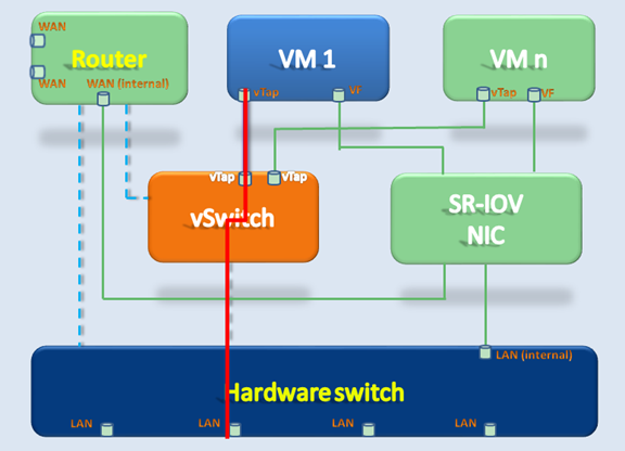
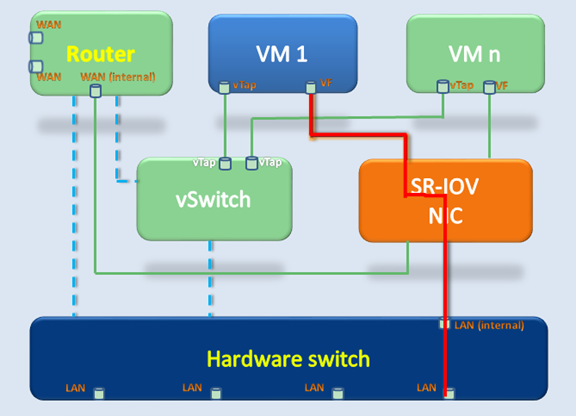
Figure 8 illustrates the forwarding path for the traffic from a VF interface on a VM to a LAN port on the device. The VF interface accesses the SR-IOV NIC, and then the SR-IOV NIC forwards the traffic to the hardware switch. Finally, the hardware switch forwards the traffic to the LAN port.
Figure 8 VF-to-LAN traffic forwarding
Restrictions: Hardware compatibility with VMs
Only the MSR3610-I-DP and MSR3610-IE-DP routers support VMs.
VM configuration tasks at a glance
To configure VMs, perform the following tasks:
1. Managing VMs
? Adding an SR-IOV NIC to a VM
? Specifying a VLAN for a VF interface
? Removing an SR-IOV NIC from a VM
? Specifying a VLAN for a vTap interface
? Removing a vTap NIC from a VM
? Allocating CPU cores to the VM plane
? Binding vCPUs to physical CPUs
? Configuring the VNC port of a VM
Managing VMs
Creating a VM
About VM creation
To create a VM, execute the install vm-name command or install a .pkg VM file. A .pkg file contains all files that make up a VM. You can use the export vm command to export the .pkg file for a VM to the hda0:/VmImages path.
Restrictions and guidelines
Before you add a disk to a VM, you must use the create-disk command to create the disk.
When you install an H3C vFW on a VM, follow these restrictions:
· If the vFW requires only one CPU core, allocate 2 GB of memory to the VM.
· If the vFW requires two CPU cores, allocate 4 GB of memory to the VM.
· If the vFW requires four CPU cores, allocate 8 GB of memory to the VM.
Prerequisites
If you are using a .pkg file to create a VM, prepare the file in advance.
Procedure
1. Enter system view.
system-view
2. Enter VMM view.
vmm
3. Install a VM. Choose one of the following methods:
? Install a VM based on the specified parameters.
install vm-name vm-name vcpu vcpu-count memory size vncport vncport disk disk-file format { raw | qcow2 } [ cdrom cdrom-file ] [ vnic { vtap [ mac mac-address ] [ vlan vlan-id ] | sriov pf pfid vf vfid [ vlan vlan-id ] } ]
? Install a VM by using a .pkg file.
install vm-pkg pkg-path
Uninstalling a VM
Prerequisites
You must shut down the VM before you can uninstall a VM.
Procedure
1. Enter system view.
system-view
2. Enter VMM view.
vmm
3. Uninstall a VM.
uninstall vm vm-name
Starting a VM
About starting a VM
Perform this task to start a VM.
Restrictions and guidelines
Make sure the VM you want to start has been created on the device and the system has sufficient memory to start the VM.
The system also allocates memory to the VM plane. As a best practice to make sure the system has sufficient memory to run the VM plane, reduce the memory allocated to VMs if multiple VMs start. If the memory is insufficient, the system automatically stops the VM that occupies the most memory.
Procedure
1. Enter system view.
system-view
2. Enter VMM view.
vmm
3. Start a VM.
start vm vm-name
Shutting down a VM
About shutting down a VM
When the device reboots, the system starts a secure process to shut down VMs. It attempts to shut down all VMs within 5 minutes. If multiple VMs are operating incorrectly, the average secure shutdown time required by each VM is 6 minutes. If the system fails to shut down a VM within 6 minutes, it will forcibly shut down that VM.
Perform this task to manually shut down a VM.
Restrictions and guidelines
|
|
CAUTION: Perform a force shutdown with caution. A force shutdown might cause data loss. |
Shutting down a VM requires an amount of time. If a process stops the VM from shutting down, you must access the VM and manually close the process.
If the VM does not have an operating system, you must specify the force keyword to forcibly shut down it.
Procedure
1. Enter system view.
system-view
2. Enter VMM view.
vmm
3. Shut down a VM.
stop vm vm-name [ force ]
Suspending a VM
About suspending a VM
Perform this task to suspend a VM. The VM will then be placed in Paused state.
Procedure
1. Enter system view.
system-view
2. Enter VMM view.
vmm
3. Suspend a VM.
suspend vm vm-name
Resuming a VM
About resuming a VM
Perform this task to resume a suspended VM.
Procedure
1. Enter system view.
system-view
2. Enter VMM view.
vmm
3. Resume a suspended VM.
resume vm vm-name
Backing up a VM
About VM backup
Perform this task to back up a VM to a .vmb file.
Restrictions and guidelines
Make sure the file path is correct and the target storage medium has sufficient storage space.
Procedure
1. Enter system view.
system-view
2. Enter VMM view.
vmm
3. Back up a VM.
backup vm vm-name backup-path
Restoring a VM
About VM restoration
Perform this task to restore a VM by using a .vmb backup file. After the restoration, the VM runs as in the point when the .vmb backup file was generated.
Restrictions and guidelines
Make sure the system has sufficient storage space to restore the VM.
Procedure
1. Enter system view.
system-view
2. Enter VMM view.
vmm
3. Restore a VM by using a .vmb backup file.
restore pakagepath package-path
Exporting a VM
About VM export
Perform this task to export a VM to a .pkg file.
Restrictions and guidelines
Make sure you have access permissions to the target path and the target path has sufficient storage space.
Procedure
1. Enter system view.
system-view
2. Enter VMM view.
vmm
3. Export a VM.
export vm vm-name
Configuring VMs
Adding a disk to a VM
About adding a disk to a VM
A VM supports one IDE controller, which can mount a maximum of four disks. The disk names are fixed at hda, hdb, hdc, and hdd, respectively, in the XML configuration file. The hdc disk is reserved for CD-ROM.
To add a disk to a VM, specify the directory that stores the disk image file for the VM.
Restrictions and guidelines
To have the add operation to take effect, you must reboot the VM.
After you add a disk to a VM, you must partition, format, and mount that disk before you can use it.
You can mount only one disk to a vFW firewall.
Procedure
1. Enter system view.
system-view
2. Enter VMM view.
vmm
3. Create a VM disk.
create-disk disk-file size size format { raw | qcow2 }
4. Add the disk to a VM.
add disk vm vm-name format { raw | qcow2 } disk-file file-path
Removing a disk from a VM
About deleting a disk from a VM
Perform this task to specify the name of a disk on a VM to remove the disk from the VM.
Restrictions and guidelines
For the deletion to take effect, you must reboot the VM.
Procedure
1. Enter system view.
system-view
2. Enter VMM view.
vmm
3. Remove a disk from a VM.
delete disk vm vm-name target target
Configuring the CD-ROM
About CD-ROM configuration
After the installation is completed, you can set the CD-ROM file to any image file for file copy between the device and the VM.
Procedure
1. Enter system view.
system-view
2. Enter VMM view.
vmm
3. Configure the CD-ROM.
set cdrom vm vm-name cdrom-file cdrom-file
Adding an SR-IOV NIC to a VM
About adding an SR-IOV NIC to a VM
The device supports the following VM network modes based on how the physical SR-IOV NIC is used:
· Passthrough—The physical NIC is allocated to a VM exclusively. The VM uses the PF interface of the physical NIC for communication.
· SR-IOV share—Multiple VMs share the physical NIC. The VMs use the VF interfaces of the physical NIC for communication.
Perform this task to allocate an SR-IOV NIC to a VM by specifying the MAC address of a PF or VF.
Restrictions and guidelines
For an SR-IOV NIC to operate on a VM, you must install an SR-IOV NIC driver on the VM.
Procedure
1. Enter system view.
system-view
2. Set the VM network mode.
vm network-mode { passthrough | sr-iov }
3. Enter VMM view.
vmm
4. Add an SR-IOV NIC to a VM. Choose one of the following tasks:
? In SR-IOV share mode, allocate a VF to the VM.
add sriov vm vm-name pf pfid vf vfid [ vlan vlan-id ]
? In passthrough mode, allocate a PF to the VM.
add sriov vm vm-name pf pfid
Specifying a VLAN for a VF interface
About specifying a VLAN for a VF interface
By default, a VF interface does not belong to any VLAN. Perform this task to specify a VLAN for a VF interface.
After you specify a VLAN for a VF interface, all packets received by and sent from the VF interface will carry VLAN tags.
Procedure
1. Enter system view.
system-view
2. Enter VMM view.
vmm
3. Specify a VLAN for a VF interface.
set sriov pf pfid vf vfid vlan vlan-id
4. Remove a VF interface from its VLAN.
undo set sriov pf pfid vf vfid vlan [ vlan-id ]
Removing an SR-IOV NIC from a VM
About removing an SR-IOV NIC from a VM
Remove a PF or VF from a VM to remove the SR-IOV NIC from that VM.
Restrictions and guidelines
For the remove operation to take effect, you must reboot the VM.
Procedure
1. Enter system view.
system-view
2. Enter VMM view.
vmm
3. Remove an SR-IOV NIC from a VM. Choose one of the following tasks:
? In SR-IOV share mode, remove a VF from the VM.
delete sriov vm vm-name pf pfid vf vfid
? In passthrough mode, remove a PF from the VM.
delete sriov vm vm-name pf pfid
Adding a vTap NIC to a VM
About adding a vTap NIC to a VM
A vTap NIC is virtualized by software. A vTap NIC is slower than an SR-IOV NIC. Howerver, you do not need to install any driver for the vTap NIC on a VM. The Comware system has reserved MAC addresses for vTap NICs. When you use the add vtap command to add a vTap NIC to a VM, follow the system prompt to select a MAC address. A vTap NIC is uniquely identified by its MAC address.
Restrictions and guidelines
You cannot add NICs with the same MAC address to a VM. VMs cannot have NICs that use the same MAC address.
Procedure
1. Enter system view.
system-view
2. Enter VMM view.
vmm
3. Add a vTap NIC to a VM.
add vtap vm vm-name mac mac-address [ vlan vlan-id ]
Specifying a VLAN for a vTap interface
About specifying a VLAN for a vTap interface
Procedure
1. Enter system view.
system-view
2. Enter VMM view.
vmm
3. Specify a VLAN for the vTap interface of a VM.
set vtap vm vm-name mac mac-address vlan vlan-id
Removing a vTap NIC from a VM
About removing a vTap NIC from a VM
Perform this task to specify the MAC address of a vTap NIC to remove the vTap NIC from a VM.
Restrictions and guidelines
For the remove operation to take effect, you must reboot the VM.
Procedure
1. Enter system view.
system-view
2. Enter VMM view.
vmm
3. Remove a vTap NIC from a VM.
delete vtap vm vm-name mac mac-address
Allocating CPU cores to the VM plane
About allocating CPU cores to the VM plane
On the MSR3610-I-DP and MSR3610-IE-DP routers, the system has the control, data, and VM planes. The virtualization functions run on the VM plane.
Perform this task to allocate CPU cores to the VM plane. The control plane is allocated one CPU core, which is fixed, and the remaining CPU cores are allocated to the data plane. By default, the control plane is allocated one CPU core, the data plane is allocated one CPU core, and the VM plane is allocated the remaining CPU cores.
Restrictions and guidelines
For the configuration in this task to take effect, you must reboot the device.
After you modify the number of CPU cores allocated to the VM plane, you must reallocate vCPUs to VMs. For the reallocation to take effect on a VM, you must reboot the VM.
Procedure
1. Enter system view.
system-view
2. Set the number of CPU cores allocated to the VM plane.
set vcpu-pool vcpu-number
Allocating vCPUs to a VM
About allocating vCPUs to a VM
Perform this task to set the number of vCPUs allocated to a VM.
Procedure
1. Enter system view.
system-view
2. Enter VMM view.
vmm
3. Set the number of vCPUs allocated to a VM.
set vcpu vm vm-name vcpu-count vcpu-count
Binding vCPUs to physical CPUs
About binding vCPUs to physical CPUs
Perform this task to bind vCPUs on a VM to physical CPUs on the device.
Procedure
1. Enter system view.
system-view
2. Enter VMM view.
vmm
3. Bind a vCPU on a VM to a physical CPU.
set vcpupin vm vm-name vcpuindex vcpuindex cpuindex cpuindex
Allocating memory to a VM
About allocating memory to a VM
Typically the Comware system requires 2 GB of memory. You can allocate the remaining memory to VMs.
Restrictions and guidelines
To ensure that a VM can operate, make sure the VM is allocated a minimum of 512 MB of memory. If the device has more than 16 GB of memory, you can allocate a maximum of 15 GB of memory to VMs.
Procedure
1. Enter system view.
system-view
2. Enter VMM view.
vmm
3. Set the amount of memory allocated to a VM.
set memory vm vm-name size size
Configuring the VNC port of a VM
About configuring the VNC port of a VM
Perform the tasks in this section to configure the VNC port of a VM. After the VM starts, you can enter the VNC port number on the VNC terminal of a PC to connect to the VM desktop.
Procedure
1. Enter system view.
system-view
2. Enter VMM view.
vmm
3. Set the VNC port number of a VM.
set vnc vm vm-name vncport vncport
4. Set the login password of the VNC port.
set vnc vm vm-name setpasswd passwd
5. Set the IP address that the VNC port of the VM listens for.
set vnc vm vm-name listen ip-address
6. Delete the login password of the VNC port.
set vnc vm vm-name delpasswd
Enabling VM auto-start
About VM auto-start
Perform this task to enable a VM to start up automatically.
Procedure
1. Enter system view.
system-view
2. Enter VMM view.
vmm
3. Enable VM auto-start.
autostart vm vm-name
By default, VM auto-start is disabled.
Display and maintenance commands for VMs
Execute display commands in any view.
|
Command |
|
|
Display the VM list. |
display vmlist |
|
Display the VM disk list. |
display vmdisklist vm vm-name |
|
Display detailed information about a VM. |
display vm vm-name |
|
Display the number of CPU cores allocated to VMs. |
display vcpu-pool |
|
Display the CPU usage of a VM. |
display vmcpu-usage vm vm-name |
|
Display the memory usage of a VM. |
display vmmem-usage vm vm-name |
|
Display SR-IOV vNIC information. |
display sriov |
|
Display network interface information about a VM. |
display vminterface vm vm-name |
|
Display the VNC port number of a VM. |
display vncport vm vm-name |
|
Display the bindings between vCPUs and physical CPUs for a VM. |
display vmcpupin vm vm-name |
|
Display disk usage information about a VM. |
display vmdisk-usage vm vm-name |
|
Display passthrough NIC information. |
display passthrough |
|
Display the VM network mode of the NIC. |
display vm-network-mode |
