- Table of Contents
-
- 06-Layer 3 - IP Routing Configuration Guide
- 00-Preface
- 01-Basic IP routing configuration
- 02-Static routing configuration
- 03-RIP configuration
- 04-OSPF configuration
- 05-IS-IS configuration
- 06-BGP configuration
- 07-Policy-based routing configuration
- 08-IPv6 static routing configuration
- 09-RIPng configuration
- 10-OSPFv3 configuration
- 11-IPv6 policy-based routing configuration
- 12-Routing policy configuration
- 13-DCN configuration
- Related Documents
-
| Title | Size | Download |
|---|---|---|
| 13-DCN configuration | 85.45 KB |
Configuring the NE ID and NE IP
Enabling the automatic report feature
Configuring the source MAC address of LLDP frames
Advertising the LLDP management address
Configuring DCN
Overview
Data communication network (DCN) is built for the network management system (NMS) to implement operation, administration, and maintenance (OAM) on the network elements (NEs).
On large-scaled networks with DCN configured, the NMS remotely manages and controls all NEs through the gateway network element (GNE), which reduces operation and maintenance costs.
On the DCN network, all NEs must operate in Area 0 of OSPF process 65535.
Basic concepts
A DCN network includes the following basic elements:
· NE—A network device managed by the NMS on the DCN network.
· GNE—The NE that is directly connected to the NMS. The NSM communicates with the GNE at the network layer or application layer and manages the NEs through the GNE.
· NE table—Stores the NE ID-to-NE IP mappings for each NE in the DCN domain. After DCN is enabled, an NE encapsulates its NE ID and NE IP in a Type-10 Opaque LSA. It floods the LSA to synchronize the mappings with other NEs in the DCN domain. The NE IP in the Type-10 Opaque LSA might be inconsistent with the NE's router ID when DCN is enabled on an OSPF network. Devices from other vendors will fail to identify the NE. To avoid this problem, make sure the following requirements are met:
? Change the router ID by modifying the NE IP. Do not change the default IP address of the DCN's loopback interface.
? Do not associate other loopback interfaces to the DCN VPN instance.
Basic features
GNE
The GNE allows the NMS to access NEs on the DCN network. The GNE provides the NE ID-to-NE IP mappings of all NEs for the Telnet users to access the target NE remotely.
NE search
The NE search feature allows the NMS to search for all NEs that are connected to the GNE. With this feature, the GNE can report information about all NEs in its NE table and the GNE itself to the NMS.
Automatic report
The automatic report feature enables the GNE to automatically report online or offline events of NEs to the NMS.
DCN configuration task list
|
(Required.) Enabling DCN |
|
(Optional.) Configuring the NE ID and NE IP |
|
(Required.) Configuring DCN VPN |
|
(Optional.) Enabling the automatic report feature |
|
(Optional.) Configuring the source MAC address of LLDP frames |
|
(Required.) Advertising the LLDP management address |
Enabling DCN
After DCN is enabled, the device assigns an NE IP to the loopback interface with the largest interface number and uses the interface for communication. The NE IP is specified as the management address and advertised in an LLDP frame. For more information about LLDP, see Layer 2—LAN Switching Configuration Guide.
To enable DCN:
|
Step |
Command |
Remarks |
|
1. Enter system view. |
system-view |
N/A |
|
2. Enable DCN and enter DCN view. |
dcn |
By default, DCN is disabled. |
Configuring the NE ID and NE IP
Typically an NE automatically generates an NE IP according to its NE ID. The automatically generated NE IP changes when the NE ID changes. When you replan your network or an NE ID conflict occurs, you can manually configure the NE ID and NE IP. The manually configured NE IP does not change when the NE ID changes.
To configure the NE ID and NE IP:
|
Step |
Command |
Remarks |
|
1. Enter system view. |
system-view |
N/A |
|
2. Enter DCN view. |
dcn |
N/A |
|
3. Configure the NE ID. |
ne-id id-number |
By default, the NE ID is automatically generated by using the 24 low-order bits of the bridge MAC address. |
|
4. Configure the NE IP. |
ne-ip ip-address { mask-length | mask } |
By default, the NE IP is automatically generated by using 129 as the eight high-order bits and the NE ID as the rest 16 bits. The mask length is 32. |
Configuring DCN VPN
Perform this task to ensure the independence of DCN services. For more information about VPN instances, see MPLS Configuration Guide.
To configure DCN VPN:
|
Step |
Command |
Remarks |
|
1. Enter system view. |
system-view |
N/A |
|
2. Create a VPN instance and enter its view. |
ip vpn-instance vpn-instance-name |
By default, no VPN instances exist. |
|
3. Quit VPN instance view. |
quit |
N/A |
|
4. Create a loopback interface and enter its view. |
interface loopback interface-number |
By default, no loopback interfaces exist. |
|
5. Associate the loopback interface with a VPN instance. |
ip binding vpn-instance vpn-instance-name |
By default, the loopback interface is not associated with a VPN instance. |
Enabling the automatic report feature
Perform this task to enable the GNE to automatically report online or offline events of NEs to the NMS.
To enable the automatic report feature:
|
Step |
Command |
Remarks |
|
1. Enter system view. |
system-view |
N/A |
|
2. Enter DCN view. |
dcn |
N/A |
|
3. Enable the automatic report feature. |
auto-report |
By default, the automatic report feature is disabled. |
Configuring the source MAC address of LLDP frames
Perform this task to configure the MAC address of the subinterface that runs Dot1q termination in the specified VLAN as the source MAC address of LLDP frames. For more information about LLDP, see Layer 2—LAN Switching Configuration Guide.
|
Step |
Command |
Remarks |
|
1. Enter system view. |
system-view |
N/A |
|
2. Enter Layer 3 Ethernet interface view. |
interface interface-type interface-number |
N/A |
|
3. Configure the MAC address of the Dot1q termination-enabled subinterface in the specified VLAN as the source MAC address of LLDP frames. |
lldp source-mac vlan vlan-id |
By default, the MAC address of the current Ethernet interface is specified as the source MAC address of LLDP frames. |
Advertising the LLDP management address
An NE on the DCN network learns the MAC address of its neighbor through LLDP. Perform this task to enable an NE to advertise the IP address of the specified loopback interface (management address) for ARP entry learning. For more information about LLDP, see Layer 2—LAN Switching Configuration Guide.
|
Step |
Command |
Remarks |
|
1. Enter system view. |
system-view |
N/A |
|
2. Enter interface view. |
interface interface-type interface-number |
N/A |
|
3. Advertise the LLDP management address. |
lldp tlv-enable basic-tlv management-address-tlv [ ip-address | interface loopback interface-number ] |
By default, the LLDP management address is not advertised. |
Enabling the system to issue the generated ARP entry to a Layer 3 Ethernet subinterface after a port receives an LLDP frame
With this feature enabled, the system performs the following operations when an interface receives an LLDP frame carrying a management address TLV in IPv4 format:
· Generates an ARP entry that contains the management address and the source MAC address of the frame.
· Issues the ARP entry to the Layer 3 subinterface associated with the specified VLAN ID in Dot1q termination.
For more information about LLDP, see Layer 2—LAN Switching Configuration Guide.
To enable the system to issue the generated ARP entry to a Layer 3 Ethernet subinterface after a port receives an LLDP frame:
|
Step |
Command |
Remarks |
|
1. Enter system view. |
system-view |
N/A |
|
2. Enter Layer 3 Ethernet subinterface view. |
interface interface-type interface-number |
N/A |
|
3. Enable the system to issue the generated ARP entry to an interface after a port receives an LLDP frame. |
lldp management-address arp-learning vlan vlan-id |
By default, the system does not issue an ARP entry to interfaces after a port receives an LLDP frame. The vlan-id argument specifies the VLAN ID associated with a Layer 3 Ethernet subinterface in Dot1q termination. |
DCN configuration examples
Network requirements
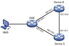
As shown in Figure 1, the GNE, Device A, and Device B run DCN in the same VPN instance. The NMS uses SNMP to manage the GNE, and the GNE automatically sends notifications to the NMS to report online or offline events of NEs.
Configuration procedure
1. Configure the GNE:
# Enable SNMP on the GNE. (Details not shown. For more information, see Network Management and Monitoring Configuration Guide.)
# Enable DCN, configure the NE ID as 100001 and NE IP as 11.1.1.1/32, and enable the automatic report feature.
<GNE> system-view
[GNE] dcn
[GNE-dcn] ne-id 100001
[GNE-dcn] ne-ip 11.1.1.1 32
[GNE-dcn] auto-report
[GNE-dcn] quit
# Create a VPN instance named dcn_vpn.
[GNE] ip vpn-instance dcn_vpn
[GNE-vpn-instance-dcn_vpn] quit
# Create interface Loopback 1023, and associate it with VPN instance dcn_vpn.
[GNE] interface loopback 1023
[GNE-LoopBack1023] ip binding vpn-instance dcn_vpn
[GNE-LoopBack1023] quit
# Enable LLDP globally.
[GNE] lldp global enable
# Enable the nearest bridge agents on GigabitEthernet 1/0/1 to advertise basic LLDP TLVs and management address TLVs. The IP address of interface Loopback 1023 is specified as the management address.
[GNE] interface gigabitethernet 1/0/1
[GNE-GigabitEthernet1/0/1] port link-mode route
[GNE-GigabitEthernet1/0/1] lldp tlv-enable basic-tlv management-address-tlv interface loopback 1023
# Configure the system to issue the generated ARP entry to the Layer 3 Ethernet subinterface associated with VLAN 4094 in Dot1q termination after GigabitEthernet 1/0/1 receives an LLDP frame.
[GNE-GigabitEthernet1/0/1] lldp management-address arp-learning vlan 4094
[GNE-GigabitEthernet1/0/1] quit
# Enable the nearest bridge agents on GigabitEthernet 1/0/2 to advertise basic LLDP TLVs and management address TLVs. The IP address of interface Loopback 1023 is specified as the management address.
[GNE] interface gigabitethernet 1/0/2
[GNE-GigabitEthernet1/0/2] port link-mode route
[GNE-GigabitEthernet1/0/2] lldp tlv-enable basic-tlv management-address-tlv interface loopback 1023
# Configure the system to issue the generated ARP entry to the Layer 3 Ethernet subinterface associated with VLAN 4094 in Dot1q termination after GigabitEthernet 1/0/2 receives an LLDP frame.
[GNE-GigabitEthernet1/0/2] lldp management-address arp-learning vlan 4094
[GNE-GigabitEthernet1/0/2] quit
# Create GigabitEthernet 1/0/1 that borrows the IP address of Loopback 1023.
[GNE] interface gigabitethernet 1/0/1
[GNE-GigabitEthernet1/0/1] ip binding vpn-instance dcn_vpn
[GNE-GigabitEthernet1/0/1] ip address unnumbered interface loopback 1023
[GNE-GigabitEthernet1/0/1] quit
# Create GigabitEthernet 1/0/2 that borrows the IP address of Loopback 1023.
[GNE] interface gigabitethernet 1/0/2
[GNE-GigabitEthernet1/0/2] ip binding vpn-instance dcn_vpn
[GNE-GigabitEthernet1/0/2] ip address unnumbered interface loopback 1023
[GNE-GigabitEthernet1/0/2] quit
# Enable OSPF process 65535 to run in VPN instance dcn_vpn, and create area 0.
[GNE] ospf 65535 vpn-instance dcn_vpn
[GNE-ospf-65535] area 0
[GNE-ospf-65535-area-0.0.0.0] network 0.0.0.0 255.255.255.255
[GNE-ospf-65535-area-0.0.0.0] quit
[GNE-ospf-65535] quit
# Set the OSPF network type for GigabitEthernet 1/0/1 to P2P.
[GNE] interface gigabitethernet 1/0/1
[GNE-GigabitEthernet1/0/1] ospf network-type p2p
[GNE-GigabitEthernet1/0/1] quit
# Set the OSPF network type for GigabitEthernet 1/0/2 to P2P.
[GNE] interface gigabitethernet 1/0/2
[GNE-GigabitEthernet1/0/2] ospf network-type p2p
[GNE-GigabitEthernet1/0/2] quit
2. Configure Device A:
# Enable DCN, configure the NE ID as 200002 and NE IP as 22.2.2.2/32.
<DeviceA> system-view
[DeviceA] dcn
[DeviceA-dcn] ne-id 200002
[DeviceA-dcn] ne-ip 22.2.2.2 32
[DeviceA-dcn] quit
# Create a VPN instance named dcn_vpn.
[DeviceA] ip vpn-instance dcn_vpn
[DeviceA-vpn-instance-dcn_vpn] quit
# Create interface Loopback 1023, and associate it with VPN instance dcn_vpn.
[DeviceA] interface loopback 1023
[DeviceA-LoopBack1023] ip binding vpn-instance dcn_vpn
[DeviceA-LoopBack1023] quit
# Enable LLDP globally.
[DeviceA] lldp global enable
# Enable the nearest bridge agents on GigabitEthernet 1/0/1 to advertise basic LLDP TLVs and management address TLVs. The IP address of interface Loopback 1023 is specified as the management address.
[DeviceA] interface gigabitethernet 1/0/1
[DeviceA-GigabitEthernet1/0/1] port link-mode route
[DeviceA-GigabitEthernet1/0/1] lldp tlv-enable basic-tlv management-address-tlv interface loopback 1023
# Configure the system to issue the generated ARP entry to the Layer 3 Ethernet subinterface associated with VLAN 4094 in Dot1q termination after GigabitEthernet 1/0/1 receives an LLDP frame.
[DeviceA-GigabitEthernet1/0/1] lldp management-address arp-learning vlan 4094
[DeviceA-GigabitEthernet1/0/1] quit
# Enable the nearest bridge agents on GigabitEthernet 1/0/2 to advertise basic LLDP TLVs and management address TLVs. The IP address of interface Loopback 1023 is specified as the management address.
[DeviceA] interface gigabitethernet 1/0/2
[DeviceA-GigabitEthernet1/0/2] port link-mode route
[DeviceA-GigabitEthernet1/0/2] lldp tlv-enable basic-tlv management-address-tlv interface loopback 1023
# Configure the system to issue the generated ARP entry to the Layer 3 Ethernet subinterface associated with VLAN 4094 in Dot1q termination after GigabitEthernet 1/0/2 receives an LLDP frame.
[DeviceA-GigabitEthernet1/0/2] lldp management-address arp-learning vlan 4094
[DeviceA-GigabitEthernet1/0/2] quit
# Create GigabitEthernet 1/0/1 that borrows the IP address of Loopback 1023.
[DeviceA] interface gigabitethernet 1/0/1
[DeviceA-GigabitEthernet1/0/1] ip binding vpn-instance dcn_vpn
[DeviceA-GigabitEthernet1/0/1] ip address unnumbered interface loopback 1023
[DeviceA-GigabitEthernet1/0/1] quit
# Create GigabitEthernet 1/0/2 that borrows the IP address of Loopback 1023.
[DeviceA] interface gigabitethernet 1/0/2
[DeviceA-GigabitEthernet1/0/2] ip binding vpn-instance dcn_vpn
[DeviceA-GigabitEthernet1/0/2] ip address unnumbered interface loopback 1023
[DeviceA-GigabitEthernet1/0/2] quit
# Enable OSPF process 65535 to run in VPN instance dcn_vpn, and create area 0.
[DeviceA] ospf 65535 vpn-instance dcn_vpn
[DeviceA-ospf-65535] area 0
[DeviceA-ospf-65535-area-0.0.0.0] network 0.0.0.0 255.255.255.255
[DeviceA-ospf-65535-area-0.0.0.0] quit
[DeviceA-ospf-65535] quit
# Set the OSPF network type for GigabitEthernet 1/0/1 to P2P.
[DeviceA] interface gigabitethernet 1/0/1
[DeviceA-GigabitEthernet1/0/1] ospf network-type p2p
[DeviceA-GigabitEthernet1/0/1] quit
# Set the OSPF network type for GigabitEthernet 1/0/2 to P2P.
[DeviceA] interface gigabitethernet 1/0/2
[DeviceA-GigabitEthernet1/0/2] ospf network-type p2p
[DeviceA-GigabitEthernet1/0/2] quit
3. Configure Device B:
# Enable DCN, configure the NE ID as 300003 and NE IP as 33.3.3.3/32.
<DeviceB> system-view
[DeviceB] dcn
[DeviceB-dcn] ne-id 300003
[DeviceB-dcn] ne-ip 33.3.3.3 32
[DeviceB-dcn] quit
# Create a VPN instance named dcn_vpn.
[DeviceB] ip vpn-instance dcn_vpn
[DeviceB-vpn-instance-dcn_vpn] quit
# Create interface Loopback 1023, and associate it with VPN instance dcn_vpn.
[DeviceB] interface loopback 1023
[DeviceB-LoopBack1023] ip binding vpn-instance dcn_vpn
[DeviceB-LoopBack1023] quit
# Enable LLDP globally.
[DeviceB] lldp global enable
# Enable the nearest bridge agents on GigabitEthernet 1/0/1 to advertise basic LLDP TLVs and management address TLVs. The IP address of interface Loopback 1023 is specified as the management address.
[DeviceB] interface gigabitethernet 1/0/1
[DeviceB-GigabitEthernet1/0/1] port link-mode route
[DeviceB-GigabitEthernet1/0/1] lldp tlv-enable basic-tlv management-address-tlv interface loopback 1023
# Configure the system to issue the generated ARP entry to the Layer 3 Ethernet subinterface associated with VLAN 4094 in Dot1q termination after GigabitEthernet 1/0/1 receives an LLDP frame.
[DeviceB-GigabitEthernet1/0/1] lldp management-address arp-learning vlan 4094
[DeviceB-GigabitEthernet1/0/1] quit
# Enable the nearest bridge agents on GigabitEthernet 1/0/2 to advertise basic LLDP TLVs and management address TLVs. The IP address of interface Loopback 1023 is specified as the management address.
[DeviceB] interface gigabitethernet 1/0/2
[DeviceB-GigabitEthernet1/0/2] port link-mode route
[DeviceB-GigabitEthernet1/0/2] lldp tlv-enable basic-tlv management-address-tlv interface loopback 1023
# Configure the system to issue the generated ARP entry to the Layer 3 Ethernet subinterface associated with VLAN 4094 in Dot1q termination after GigabitEthernet 1/0/2 receives an LLDP frame.
[DeviceB-GigabitEthernet1/0/2] lldp management-address arp-learning vlan 4094
[DeviceB-GigabitEthernet1/0/2] quit
# Create GigabitEthernet 1/0/1 that borrows the IP address of Loopback 1023.
[DeviceB] interface gigabitethernet 1/0/1
[DeviceB-GigabitEthernet1/0/1] ip binding vpn-instance dcn_vpn
[DeviceB-GigabitEthernet1/0/1] ip address unnumbered interface loopback 1023
[DeviceB-GigabitEthernet1/0/1] quit
# Create GigabitEthernet 1/0/2 that borrows the IP address of Loopback 1023.
[DeviceB] interface gigabitethernet 1/0/2
[DeviceB-GigabitEthernet1/0/2] ip binding vpn-instance dcn_vpn
[DeviceB-GigabitEthernet1/0/2] ip address unnumbered interface loopback 1023
[DeviceB-GigabitEthernet1/0/2] quit
# Enable OSPF process 65535 to run in VPN instance dcn_vpn, and create area 0.
[DeviceB] ospf 65535 vpn-instance dcn_vpn
[DeviceB-ospf-65535] area 0
[DeviceB-ospf-65535-area-0.0.0.0] network 0.0.0.0 255.255.255.255
[DeviceB-ospf-65535-area-0.0.0.0] quit
[DeviceB-ospf-65535] quit
# Set the OSPF network type for GigabitEthernet 1/0/1 to P2P.
[DeviceB] interface gigabitethernet 1/0/1
[DeviceB-GigabitEthernet1/0/1] ospf network-type p2p
[DeviceB-GigabitEthernet1/0/1] quit
# Set the OSPF network type for GigabitEthernet 1/0/2 to P2P.
[DeviceB] interface gigabitethernet 1/0/2
[DeviceB-GigabitEthernet1/0/2] ospf network-type p2p
[DeviceB-GigabitEthernet1/0/2] quit
Verifying the configuration
# Display brief DCN information on the GNE.
[GNE] display dcn
DCN Brief Information
NE ID : 0x100001
NE IP : 11.1.1.1
Mask : 255.255.255.255
DCN interface: LoopBack1023
Auto report : Enabled
# Display all DCN NE information on the GNE.
[GNE] display dcn ne-info
DCN Network Elements Information
NE ID NE IP Metric Device Type
0x100001 11.1.1.1 0 H3C S7506E
0x200002 22.2.2.2 1 H3C S7506E
0x300003 33.3.3.3 1 H3C S7506E
Total number: 3
The output shows that GNE, Device A, and Device B are online. The GNE notifies the NMS of the online event. You can successfully ping the NE IP addresses of Device A and Device B from the GNE.
# Remove Device B from the DCN network and display all DCN NE information for the GNE.
[GNE] display dcn ne-info
DCN Network Elements Information
NE ID NE IP Metric Device Type
0x100001 11.1.1.1 0 H3C S7506E
0x200002 22.2.2.2 1 H3C S7506E
Total number: 2
The output shows that GNE and Device A are online. The GNE notifies the NMS of the offline event of Device B. You can still successfully ping the NE IP address of Device A from the GNE.