- Table of Contents
-
- 06-Layer 3 - IP Routing Configuration Guide
- 00-Preface
- 01-Basic IP routing configuration
- 02-Static routing configuration
- 03-RIP configuration
- 04-OSPF configuration
- 05-IS-IS configuration
- 06-BGP configuration
- 07-Policy-based routing configuration
- 08-IPv6 static routing configuration
- 09-RIPng configuration
- 10-OSPFv3 configuration
- 11-IPv6 policy-based routing configuration
- 12-Routing policy configuration
- 13-DCN configuration
- Related Documents
-
| Title | Size | Download |
|---|---|---|
| 12-Routing policy configuration | 129.18 KB |
Contents
Configuring an extended community list
Configuring the continue clause
Displaying and maintaining the routing policy
Routing policy configuration examples
Configuring a routing policy for redistributing static routes to RIP
Configuring a routing policy for redistributing IS-IS routes to OSPF
Routing policy configuration example for IPv6 route redistribution
Configuring routing policies
Overview
Routing policies control routing paths by filtering and modifying routing information. This chapter describes both IPv4 and IPv6 routing policies.
Routing policies can filter advertised, received, and redistributed routes, and modify attributes for specific routes.
To configure a routing policy:
1. Configure filters based on route attributes, such as destination address and the advertising router's address.
2. Create a routing policy and apply filters to the routing policy.
Filters
Routing policies can use the following filters to match routes.
ACL
ACLs include IPv4 ACLs and IPv6 ACLs. An ACL can match the destination or next hop of routes.
For more information about ACLs, see ACL and QoS Configuration Guide.
IP prefix list
IP prefix lists include IPv4 prefix lists and IPv6 prefix lists.
An IP prefix list matches the destination address of routes. You can use the gateway option to receive routes only from specific routers. For more information about the gateway option, see "Configuring RIP" and "Configuring OSPF."
An IP prefix list can contain multiple items that specify prefix ranges. Each destination IP address prefix of a route is compared with these items in ascending order of their index numbers. A prefix matches the IP prefix list if it matches one item in the list.
AS path list
An AS path list matches the AS_PATH attribute of BGP routes.
For more information about AS path lists, see "Configuring BGP."
Community list
A community list matches the COMMUNITY attribute of BGP routes.
For more information about community lists, see "Configuring BGP."
Extended community list
An extended community list matches the extended community attribute (Route-Target for VPN and Site of Origin) of BGP routes.
For more information about extended community lists, see MPLS Configuration Guide.
MAC list
A MAC list matches MAC addresses contained in EVI IS-IS packets.
A MAC list can contain multiple items that specify MAC address ranges. Each MAC address entry in an EVI IS-IS packet is compared with these items in ascending order of their index numbers. A MAC address entry matches the MAC list if it matches one item in the list.
Routing policy
A routing policy can contain multiple nodes, which are in a logical OR relationship. A node with a smaller number is matched first. A route matches the routing policy if it matches one node (except the node configured with the continue clause) in the routing policy.
Each node has a match mode of permit or deny.
· permit—Specifies the permit match mode for a routing policy node. If a route meets all the if-match clauses of the node, it is handled by the apply clauses of the node. The route is not compared with the next node unless the continue clause is configured. If a route does not meet all the if-match clauses of the node, it is compared with the next node.
· deny—Specifies the deny match mode for a routing policy node. The apply and continue clauses of a deny node are never executed. If a route meets all the if-match clauses of the node, it is denied without being compared with the next node. If a route does not meet all the if-match clauses of the node, it is compared with the next node.
A node can contain a set of if-match, apply, and continue clauses.
· if-match clauses—Specify the match criteria that match the attributes of routes. The if-match clauses are in a logical AND relationship. A route must meet all the if-match clauses to match the node.
· apply clauses—Specify the actions to be taken on permitted routes, such as modifying a route attribute.
· continue clause—Specifies the next node. A route that matches the current node (permit node) must match the specified next node in the same routing policy. The continue clause combines the if-match and apply clauses of the two nodes to improve flexibility of the routing policy.
Follow these guidelines when you configure if-match, apply, and continue clauses:
· If you only want to filter routes, do not configure apply clauses.
· If you do not configure any if-match clauses for a permit node, the node will permit all routes.
· Configure a permit node containing no if-match or apply clauses following multiple deny nodes to allow unmatched routes to pass.
Configuring filters
Configuration prerequisites
Determine the IP prefix list name, matching address range, and community list number.
Configuring an IP prefix list
Configuring an IPv4 prefix list
If all the items are set to deny mode, no routes can pass the IPv4 prefix list. To permit unmatched IPv4 routes, you must configure the permit 0.0.0.0 0 less-equal 32 item following multiple deny items.
To configure an IPv4 prefix list:
|
Step |
Command |
Remarks |
|
1. Enter system view. |
system-view |
N/A |
|
2. Configure an IPv4 prefix list. |
ip prefix-list prefix-list-name [ index index-number ] { deny | permit } ip-address mask-length [ greater-equal min-mask-length ] [ less-equal max-mask-length ] |
By default, no IPv4 prefix lists exist. |
Configuring an IPv6 prefix list
If all items are set to deny mode, no routes can pass the IPv6 prefix list. To permit unmatched IPv6 routes, you must configure the permit :: 0 less-equal 128 item following multiple deny items.
To configure an IPv6 prefix list:
|
Step |
Command |
Remarks |
|
1. Enter system view. |
system-view |
N/A |
|
2. Configure an IPv6 prefix list. |
ipv6 prefix-list prefix-list-name [ index index-number ] { deny | permit } ipv6-address { prefix-length | inverse inverse-prefix-length [ greater-equal min-prefix-length ] [ less-equal max-prefix-length ] } |
By default, no IPv6 prefix lists exist. |
Configuring an AS path list
You can configure multiple items for an AS path list that is identified by a number. The relationship between the items is logical OR. A route matches the AS path list if it matches one item in the list.
To configure an AS path list:
|
Step |
Command |
Remarks |
|
1. Enter system view. |
system-view |
N/A |
|
2. Configure an AS path list. |
ip as-path as-path-number { deny | permit } regular-expression |
By default, no AS path lists exist. |
Configuring a community list
You can configure multiple items for a community list that is identified by a number. The relationship between the items is logical OR. A route matches the community list if it matches one item in the list.
To configure a community list:
|
Step |
Command |
Remarks |
|
1. Enter system view. |
system-view |
N/A |
|
2. Configure a community list. |
· Configure a basic community list: · Configure an advanced community list: |
By default, no community lists exist. |
Configuring an extended community list
You can configure multiple items for an extended community list that is identified by a number. The relationship between the items is logical OR. A route matches the extended community list if it matches one item in the list.
To configure an extended community list:
|
Step |
Command |
Remarks |
|
1. Enter system view. |
system-view |
N/A |
|
2. Configure an extended community list. |
ip extcommunity-list ext-comm-list-number { deny | permit } { rt route-target | soo site-of-origin }&<1-32> |
By default, no extended community lists exist. |
Configuring a MAC list
If all the items are set to deny mode, no MAC address entries can pass the MAC list. To permit unmatched MAC address entries, you must configure the permit 0-0-0 0 item following multiple deny items.
The MAC list filter applies only to EVI IS-IS. For information about EVI IS-IS, see EVI Configuration Guide.
To configure a MAC list:
|
Step |
Command |
Remarks |
|
1. Enter system view. |
system-view |
N/A |
|
2. Configure a MAC list. |
mac-list mac-list-name [ index index-number ] { deny | permit } mac-address [ mask-length ] |
By default, no MAC lists exist. |
Configuring a routing policy
Configuration prerequisites
Configure filters and routing protocols, and determine the routing policy name, node numbers, match criteria, and the attributes to be modified.
Creating a routing policy
For a routing policy that has more than one node, configure a minimum of one permit node. A route that does not match any node cannot pass the routing policy. If all the nodes are in deny mode, no routes can pass the routing policy.
To create a routing policy:
|
Step |
Command |
Remarks |
|
1. Enter system view. |
system-view |
N/A |
|
2. Create a routing policy and a node, and enter routing policy node view. |
route-policy route-policy-name { deny | permit } node node-number |
By default, no routing policies exist. |
Configuring if-match clauses
You can either specify no if-match clauses or multiple if-match clauses for a routing policy node. If no if-match clause is specified for a permit node, all routes can pass the node. If no if-match clause is specified for a deny node, no routes can pass the node.
The if-match clauses of a routing policy node have a logical AND relationship. A route must meet all if-match clauses before it can be executed by the apply clauses of the node. If an if-match command exceeds the maximum length, multiple if-match clauses of the same type are generated. These clauses have a logical OR relationship. A route only needs to meet one of them.
To configure if-match clauses:
|
Step |
Command |
Remarks |
|
1. Enter system view. |
system-view |
N/A |
|
2. Enter routing policy node view. |
route-policy route-policy-name { deny | permit } node node-number |
N/A |
|
3. Match routes whose destination, next hop, or source address matches an ACL or prefix list. |
· Match IPv4 routes whose destination, next hop,
or source address matches an ACL or IPv4 prefix list: · Match IPv6 routes whose destination, next hop,
or source address matches an ACL or IPv6 prefix list: |
By default, no ACL or prefix list match criterion is configured. If the ACL used by an if-match clause does not exist, the clause is always matched. If no rules of the specified ACL are matched or the match rules are inactive, the clause is not matched. The ACL specified in an if-match clause must be a non-VPN ACL. All IPv6 routes match a node if the if-match clauses of the node use only IPv4 ACLs. All IPv4 routes match a node if the if-match clauses of the node use only IPv6 ACLs. |
|
4. Match BGP routes whose AS_PATH attribute matches a specified AS path list. |
if-match as-path as-path-number&<1-32> |
By default, no AS path match criterion is configured. |
|
5. Match BGP routes whose COMMUNITY attribute matches a specified community list. |
if-match community { { basic-community-list-number | name comm-list-name } [ whole-match ] | adv-community-list-number }&<1-32> |
By default, no COMMUNITY match criterion is matched. |
|
6. Match routes having the specified cost. |
if-match cost cost-value |
By default, no cost match criterion is configured. |
|
7. Match BGP routes whose extended community attribute matches a specified extended community list. |
if-match extcommunity ext-comm-list-number&<1-32> |
By default, no extended community list match criterion is configured. |
|
8. Match routes having the specified output interface. |
if-match interface { interface-type interface-number }&<1-16> |
By default, no output interface match criterion is configured. This command is not supported by BGP. |
|
9. Match BGP routes having the specified local preference. |
if-match local-preference preference |
By default, no local preference is configured for BGP routes. |
|
10. Match BGP routes with the specified RPKI validation state. |
if-match rpki { invalid | not-found | valid } |
By default, no BGP route match criteria are configured. |
|
11. Match MAC addresses in EVI IS-IS packets. |
if-match mac-list mac-list-name |
By default, no MAC list match criterion is configured. The MAC list match criterion applies only to EVI IS-IS. For information about EVI IS-IS, see EVI Configuration Guide. |
|
12. Match routes having MPLS labels. |
if-match mpls-label |
By default, no MPLS label match criterion is configured. |
|
13. Match routes having the specified route type. |
if-match route-type { bgp-evpn-imet | bgp-evpn-ip-prefix | bgp-evpn-mac-ip | external-type1 | external-type1or2 | external-type2 | internal | is-is-level-1 | is-is-level-2 | nssa-external-type1 | nssa-external-type1or2 | nssa-external-type2 } * |
By default, no route type match criterion is configured. |
|
14. Match IGP routes having the specified tag value. |
if-match tag tag-value |
By default, no tag match criterion is configured. |
|
15. Match VLANs in EVI IS-IS packets. |
if-match vlan vlan-list |
By default, no VLAN match criterion is configured. The VLAN match criterion applies only to EVI IS-IS. For information about EVI IS-IS, see EVI Configuration Guide. |
|
16. Match routes with the specified L3VNI. |
if-match l3-vni vxlan-id |
By default, no L3VNI match criterion is configured. |
Configuring apply clauses
Except for the apply commands used for setting the next hop for IPv4 and IPv6 routes, all apply commands are the same for IPv4 and IPv6 routing.
To configure apply clauses:
|
Step |
Command |
Remarks |
|
1. Enter system view. |
system-view |
N/A |
|
2. Enter routing policy node view. |
route-policy route-policy-name { deny | permit } node node-number |
N/A |
|
3. Set the AS_PATH attribute for BGP routes. |
By default, no AS_PATH attribute is set for BGP routes. |
|
|
4. Delete the specified COMMUNITY attribute for BGP routes. |
apply comm-list { comm-list-number | comm-list-name } delete |
By default, no COMMUNITY attribute is deleted for BGP routes. |
|
5. Set the specified COMMUNITY attribute for BGP routes. |
apply community { none | additive | { community-number&<1-32> | aa:nn&<1-32> | internet | no-advertise | no-export | no-export-subconfed } * [ additive ] } |
By default, no community attribute is set for BGP routes. |
|
6. Set a cost for routes. |
apply cost [ + | - ] cost-value |
By default, no cost is set for routes. |
|
7. Set a cost type for routes. |
apply cost-type { external | internal | type-1 | type-2 } |
By default, no cost type is set for routes. |
|
8. Set the RT extended community attribute for BGP routes. |
apply extcommunity { rt route-target }&<1-32> [ additive ] |
By default, no RT extended community attribute is set for BGP routes. |
|
9. Set the SoO extended community attribute for BGP routes. |
apply extcommunity soo site-of-origin&<1-32> [ additive ] |
By default, no SoO extended community attribute is set for BGP routes. |
|
10. Set the next hop for routes. |
· Set the next hop for IPv4 routes: · Set the next hop for IPv6 routes: |
By default, no next hop is set for IPv4 or IPv6 routes. The apply ip-address next-hop and apply ipv6 next-hop commands do not apply to redistributed IPv4 and IPv6 routes. |
|
11. Set an IP precedence for matching routes. |
apply ip-precedence { value | clear } |
By default, no IP precedence is set. |
|
12. Redistribute routes to the specified IS-IS level. |
apply isis { level-1 | level-1-2 | level-2 } |
By default, routes are not redistributed into the specified IS-IS level. |
|
13. Set a local preference for BGP routes. |
apply local-preference preference |
By default, no local preference is set for BGP routes. |
|
14. Set MPLS labels. |
apply mpls-label |
By default, no MPLS label is set. |
|
15. Set the ORIGIN attribute for BGP routes. |
apply origin { egp as-number | igp | incomplete } |
By default, no ORIGIN attribute is set for BGP routes. |
|
16. Set a preference. |
apply preference preference |
By default, no preference is set. |
|
17. Set a preferred value for BGP routes. |
apply preferred-value preferred-value |
By default, no preferred value is set for BGP routes. |
|
18. Set a prefix priority. |
apply prefix-priority { critical | high | medium } |
By default, no prefix priority is set, which means the prefix priority is low. |
|
19. Set a local QoS ID for matching routes. |
apply qos-local-id { local-id-value | clear } |
By default, no local QoS ID is set. |
|
20. Set a tag value for IGP routes. |
apply tag tag-value |
By default, no tag value is set for IGP routes. |
|
21. Set a traffic index for BGP routes. |
apply traffic-index { value | clear } |
By default, no traffic index is set for BGP routes. |
|
22. Set a backup link for fast reroute (FRR). |
· Set an IPv4 backup link for FRR: · Set an IPv6 backup link for FRR: |
By default, no backup link is set for FRR. |
|
23. Set an L3VNI. |
apply l3-vni vxlan-id |
By default, no L3VNI is set. |
Configuring the continue clause
Follow these guidelines when you configure the continue clause to combine multiple nodes:
· If you configure an apply clause that sets different attribute values on all the nodes, the apply clause of the node configured most recently takes effect.
· If you configure the following apply clauses on all the nodes, the apply clause of each node takes effect:
¡ apply as-path without the replace keyword.
¡ apply cost with the + or – keyword.
¡ apply community with the additive keyword.
¡ apply extcommunity with the additive keyword.
· The apply comm-list delete clause configured on the current node cannot delete the community attributes set by the apply community clauses of the preceding nodes.
To configure the continue clause:
|
Step |
Command |
Remarks |
|
1. Enter system view. |
system-view |
N/A |
|
2. Enter routing policy node view. |
route-policy route-policy-name { deny | permit } node node-number |
N/A |
|
3. Specify the next node to be matched. |
By default, no continue clause is configured. The specified next node must have a larger number than the current node. |
Displaying and maintaining the routing policy
Execute display commands in any view and reset commands in user view.
|
Task |
Command |
|
Display BGP AS path list information. |
display ip as-path [ as-path-number ] |
|
Display BGP community list information. |
display ip community-list [ basic-community-list-number | adv-community-list-number | name comm-list-name ] |
|
Display BGP extended community list information. |
display ip extcommunity-list [ ext-comm-list-number ] |
|
Display IPv4 prefix list statistics. |
display ip prefix-list [ name prefix-list-name ] |
|
Display IPv6 prefix list statistics. |
display ipv6 prefix-list [ name prefix-list-name ] |
|
Display MAC list statistics. |
display mac-list [ name mac-list-name ] |
|
Display routing policy information. |
display route-policy [ name route-policy-name ] |
|
Clear IPv4 prefix list statistics. |
reset ip prefix-list [ prefix-list-name ] |
|
Clear IPv6 prefix list statistics. |
reset ipv6 prefix-list [ prefix-list-name ] |
|
Clear MAC list statistics. |
reset mac-list [ mac-list-name ] |
Routing policy configuration examples
Configuring a routing policy for redistributing static routes to RIP
Network requirements
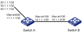
As shown in Figure 1, Switch A exchanges routing information with Switch B by using RIP.
On Switch A, configure three static routes. Use a routing policy to configure Switch B to redistribute networks 20.1.1.1/32 and 40.1.1.1/32 and block network 30.1.1.1/32.
Configuration procedure
1. Configure Switch A:
# Configure IP addresses for interfaces VLAN-interface 100 and VLAN-interface 200.
<SwitchA> system-view
[SwitchA] interface vlan-interface 100
[SwitchA-vlan-interface100] ip address 10.1.1.1 30
[SwitchA-vlan-interface100] quit
[SwitchA] interface vlan-interface 200
[SwitchA-vlan-interface200] ip address 11.1.1.1 30
[SwitchA-vlan-interface200] quit
# Enable RIP on interface VLAN-interface 100.
[SwitchA] interface vlan-interface 100
[SwitchA-vlan-interface100] rip 1 enable
[SwitchA-vlan-interface100] quit
# Configure three static routes and set the next hop of the three routes to 11.1.1.2.
[SwitchA] ip route-static 20.1.1.1 32 11.1.1.2
[SwitchA] ip route-static 30.1.1.1 32 11.1.1.2
[SwitchA] ip route-static 40.1.1.1 32 11.1.1.2
# Configure a routing policy.
[SwitchA] ip prefix-list a index 10 permit 30.1.1.1 32
[SwitchA] route-policy static2rip deny node 0
[SwitchA-route-policy-static2rip-0] if-match ip address prefix-list a
[SwitchA-route-policy-static2rip-0] quit
[SwitchA] route-policy static2rip permit node 10
[SwitchA-route-policy-static2rip-10] quit
# Enable RIP and apply routing policy static2rip to filter redistributed static routes.
[SwitchA] rip
[SwitchA-rip-1] import-route static route-policy static2rip
2. Configure Switch B:
# Configure an IP address for interface VLAN-interface 100.
<SwitchB> system-view
[SwitchB] interface vlan-interface 100
[SwitchB-vlan-interface100] ip address 10.1.1.2 30
# Enable RIP.
[SwitchB] rip
[SwitchB-rip-1] quit
# Enable RIP on the interface.
[SwitchB] interface vlan-interface 100
[SwitchB-vlan-interface100] rip 1 enable
[SwitchB-vlan-interface100] quit
Verifying the configuration
# Display the routing table information on Switch B.
<Switch B>display ip routing-table
Destinations : 14 Routes : 14
Destination/Mask Proto Pre Cost NextHop Interface
0.0.0.0/32 Direct 0 0 127.0.0.1 InLoop0
10.1.1.0/30 Direct 0 0 10.1.1.2 Vlan100
10.1.1.0/32 Direct 0 0 10.1.1.2 Vlan100
10.1.1.2/32 Direct 0 0 127.0.0.1 InLoop0
10.1.1.3/32 Direct 0 0 10.1.1.2 Vlan100
20.0.0.0/8 RIP 100 1 10.1.1.1 Vlan100
40.0.0.0/8 RIP 100 1 10.1.1.1 Vlan100
127.0.0.0/8 Direct 0 0 127.0.0.1 InLoop0
127.0.0.0/32 Direct 0 0 127.0.0.1 InLoop0
127.0.0.1/32 Direct 0 0 127.0.0.1 InLoop0
127.255.255.255/32 Direct 0 0 127.0.0.1 InLoop0
224.0.0.0/4 Direct 0 0 0.0.0.0 NULL0
224.0.0.0/24 Direct 0 0 0.0.0.0 NULL0
255.255.255.255/32 Direct 0 0 127.0.0.1 InLoop
Configuring a routing policy for redistributing IS-IS routes to OSPF
Network requirements
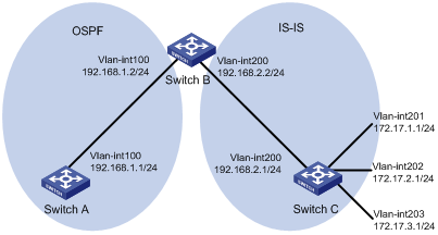
As shown in Figure 2, Switch B exchanges routing information with Switch A by using OSPF and with Switch C by using IS-IS.
On Switch B, enable route redistribution from IS-IS to OSPF. Use a routing policy to set the cost of route 172.17.1.0/24 to 100 and the tag of route 172.17.2.0/24 to 20.
Configuration procedure
1. Specify IP addresses for interfaces. (Details not shown.)
2. Configure IS-IS:
# Configure Switch C.
<SwitchC> system-view
[SwitchC] isis
[SwitchC-isis-1] is-level level-2
[SwitchC-isis-1] network-entity 10.0000.0000.0001.00
[SwitchC-isis-1] quit
[SwitchC] interface vlan-interface 200
[SwitchC-Vlan-interface200] isis enable
[SwitchC-Vlan-interface200] quit
[SwitchC] interface vlan-interface 201
[SwitchC-Vlan-interface201] isis enable
[SwitchC-Vlan-interface201] quit
[SwitchC] interface vlan-interface 202
[SwitchC-Vlan-interface202] isis enable
[SwitchC-Vlan-interface202] quit
[SwitchC] interface vlan-interface 203
[SwitchC-Vlan-interface203] isis enable
[SwitchC-Vlan-interface203] quit
# Configure Switch B.
<SwitchB> system-view
[SwitchB] isis
[SwitchB-isis-1] is-level level-2
[SwitchB-isis-1] network-entity 10.0000.0000.0002.00
[SwitchB-isis-1] quit
[SwitchB] interface vlan-interface 200
[SwitchB-Vlan-interface200] isis enable
[SwitchB-Vlan-interface200] quit
3. Configure OSPF and route redistribution:
# Configure OSPF on Switch A.
<SwitchA> system-view
[SwitchA] ospf
[SwitchA-ospf-1] area 0
[SwitchA-ospf-1-area-0.0.0.0] network 192.168.1.0 0.0.0.255
[SwitchA-ospf-1-area-0.0.0.0] quit
[SwitchA-ospf-1] quit
# On Switch B, configure OSPF and enable route redistribution from IS-IS to OSPF.
[SwitchB] ospf
[SwitchB-ospf-1] area 0
[SwitchB-ospf-1-area-0.0.0.0] network 192.168.1.0 0.0.0.255
[SwitchB-ospf-1-area-0.0.0.0] quit
[SwitchB-ospf-1] import-route isis 1
[SwitchB-ospf-1] quit
# Display the OSPF routing table on Switch A to view redistributed routes.
[SwitchA] display ospf routing
OSPF Process 1 with Router ID 192.168.1.1
Routing Tables
Routing for Network
Destination Cost Type NextHop AdvRouter Area
192.168.1.0/24 1 Stub 192.168.1.1 192.168.1.1 0.0.0.0
Routing for ASEs
Destination Cost Type Tag NextHop AdvRouter
172.17.1.0/24 1 Type2 1 192.168.1.2 192.168.2.2
172.17.2.0/24 1 Type2 1 192.168.1.2 192.168.2.2
172.17.3.0/24 1 Type2 1 192.168.1.2 192.168.2.2
Total Nets: 4
Intra Area: 1 Inter Area: 0 ASE: 3 NSSA: 0
4. Configure filtering lists:
# Configure IPv4 basic ACL 2002 to permit route 172.17.2.0/24.
[SwitchB] acl basic 2002
[SwitchB-acl-ipv4-basic-2002] rule permit source 172.17.2.0 0.0.0.255
[SwitchB-acl-ipv4-basic-2002] quit
# Configure IP prefix list prefix-a to permit route 172.17.1.0/24.
[SwitchB] ip prefix-list prefix-a index 10 permit 172.17.1.0 24
5. Configure a routing policy.
[SwitchB] route-policy isis2ospf permit node 10
[SwitchB-route-policy-isis2ospf-10] if-match ip address prefix-list prefix-a
[SwitchB-route-policy-isis2ospf-10] apply cost 100
[SwitchB-route-policy-isis2ospf-10] quit
[SwitchB] route-policy isis2ospf permit node 20
[SwitchB-route-policy-isis2ospf-20] if-match ip address acl 2002
[SwitchB-route-policy-isis2ospf-20] apply tag 20
[SwitchB-route-policy-isis2ospf-20] quit
[SwitchB] route-policy isis2ospf permit node 30
[SwitchB-route-policy-isis2ospf-30] quit
6. Apply the routing policy to route redistribution:
# On Switch B, enable route redistribution from IS-IS to OSPF and apply the routing policy.
[SwitchB] ospf
[SwitchB-ospf-1] import-route isis 1 route-policy isis2ospf
[SwitchB-ospf-1] quit
# Display the OSPF routing table on Switch A.
[SwitchA] display ospf routing
OSPF Process 1 with Router ID 192.168.1.1
Routing Tables
Routing for Network
Destination Cost Type NextHop AdvRouter Area
192.168.1.0/24 1 Transit 192.168.1.1 192.168.1.1 0.0.0.0
Routing for ASEs
Destination Cost Type Tag NextHop AdvRouter
172.17.1.0/24 100 Type2 1 192.168.1.2 192.168.2.2
172.17.2.0/24 1 Type2 20 192.168.1.2 192.168.2.2
172.17.3.0/24 1 Type2 1 192.168.1.2 192.168.2.2
Total Nets: 4
Intra Area: 1 Inter Area: 0 ASE: 3 NSSA: 0
The output shows that the cost of route 172.17.1.0/24 is 100 and the tag of route 172.17.2.0/24 is 20.
Routing policy configuration example for IPv6 route redistribution
Network requirements
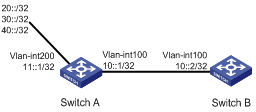
As shown in Figure 3:
· Run RIPng on Switch A and Switch B.
· Configure three static routes on Switch A.
· On Switch A, apply a routing policy to redistribute static routes 20::/32 and 40::/32 and deny route 30::/32.
Configuration procedure
1. Configure Switch A:
# Configure IPv6 addresses for VLAN-interface 100 and VLAN-interface 200.
<SwitchA> system-view
[SwitchA] interface vlan-interface 100
[SwitchA-Vlan-interface100] ipv6 address 10::1 32
[SwitchA-Vlan-interface100] quit
[SwitchA] interface vlan-interface 200
[SwitchA-Vlan-interface200] ipv6 address 11::1 32
[SwitchA-Vlan-interface200] quit
# Enable RIPng on VLAN-interface 100.
[SwitchA] interface vlan-interface 100
[SwitchA-Vlan-interface100] ripng 1 enable
[SwitchA-Vlan-interface100] quit
# Configure three static routes with next hop 11::2, and make sure the static routes are active.
[SwitchA] ipv6 route-static 20:: 32 11::2
[SwitchA] ipv6 route-static 30:: 32 11::2
[SwitchA] ipv6 route-static 40:: 32 11::2
# Configure a routing policy.
[SwitchA] ipv6 prefix-list a index 10 permit 30:: 32
[SwitchA] route-policy static2ripng deny node 0
[SwitchA-route-policy-static2ripng-0] if-match ipv6 address prefix-list a
[SwitchA-route-policy-static2ripng-0] quit
[SwitchA] route-policy static2ripng permit node 10
[SwitchA-route-policy-static2ripng-10] quit
# Enable RIPng and apply the routing policy to static route redistribution.
[SwitchA] ripng
[SwitchA-ripng-1] import-route static route-policy static2ripng
2. Configure Switch B:
# Configure the IPv6 address for VLAN-interface 100.
<SwitchB> system-view
[SwitchB] interface vlan-interface 100
[SwitchB-Vlan-interface100] ipv6 address 10::2 32
# Enable RIPng.
[SwitchB] ripng
[SwitchB-ripng-1] quit
# Enable RIPng on VLAN-interface 100.
[SwitchB] interface vlan-interface 100
[SwitchB-Vlan-interface100] ripng 1 enable
[SwitchB-Vlan-interface100] quit
Verifying the configuration
# Display the RIPng routing table on Switch B.
[SwitchB] display ripng 1 route
Route Flags: A - Aging, S - Suppressed, G - Garbage-collect
----------------------------------------------------------------
Peer FE80::7D58:0:CA03:1 on Vlan-interface 100
Destination 10::/32,
via FE80::7D58:0:CA03:1, cost 1, tag 0, A, 18 secs
Destination 20::/32,
via FE80::7D58:0:CA03:1, cost 1, tag 0, A, 8 secs
Destination 40::/32,
via FE80::7D58:0:CA03:1, cost 1, tag 0, A, 3 secs