- Table of Contents
- Related Documents
-
| Title | Size | Download |
|---|---|---|
| 02-Ethernet interface configuration | 176.89 KB |
Configuring Ethernet interfaces
Configuring a management Ethernet interface
Ethernet interface naming conventions
Configuring common Ethernet interface settings
Splitting a 40-GE interface and combining 10-GE breakout interfaces
Changing the interface type of 100-GE interfaces in batches
Configuring basic settings of an Ethernet interface
Configuring basic settings of an Ethernet subinterface
Configuring the link mode of an Ethernet interface
Configuring jumbo frame support
Configuring physical state change suppression on an Ethernet interface
Configuring dampening on an Ethernet interface
Enabling link flapping protection on an interface
Enabling loopback testing on an Ethernet interface
Configuring generic flow control on an Ethernet interface
Enabling EEE on an Ethernet interface
Setting the statistics polling interval
Forcibly bringing up a fiber port
Configuring a Layer 2 Ethernet interface
Configuring storm control on an Ethernet interface
Setting speed options for autonegotiation on an Ethernet interface
Setting the MDIX mode of an Ethernet interface
Testing the cable connection of an Ethernet interface
Enabling bridging on an Ethernet interface
Configuring a Layer 3 Ethernet interface or subinterface
Setting the MTU for an Ethernet interface or subinterface
Displaying and maintaining an Ethernet interface or subinterface
Configuring Ethernet interfaces
The Switch Series supports Ethernet interfaces, management Ethernet interfaces, and Console interfaces.
Your device supports the following types of Ethernet interfaces:
· Layer 2 Ethernet interfaces—Physical Ethernet interfaces operating at the data link layer (Layer 2) to switch packets.
· Layer 3 Ethernet interfaces—Physical Ethernet interfaces operating at the network layer (Layer 3) to route packets. You can assign an IP address to a Layer 3 Ethernet interface.
· Layer-configurable Ethernet interfaces—Physical Ethernet interfaces that can be configured to operate in bridge mode as Layer 2 Ethernet interfaces or in route mode as Layer 3 Ethernet interfaces.
· Layer 3 Ethernet subinterfaces—Logical interfaces operating at the network layer. You can assign an IP address to a Layer 3 Ethernet subinterface. On a Layer 3 Ethernet interface, you can create multiple Layer 3 subinterfaces.
This chapter describes how to configure management Ethernet interfaces and Ethernet interfaces.
Configuring a management Ethernet interface
About management Ethernet interface
A management Ethernet interface uses an RJ-45/LC connector. You can connect the interface to a PC for software loading and system debugging, or connect it to a remote NMS for remote system management.
· In standalone mode:
¡ When the switch has multiple management Ethernet interfaces, only the management Ethernet interface on the active MPU processes management traffic.
¡ When the management Ethernet interface on the active MPU fails, the management Ethernet interface on the standby MPU takes over to process management traffic.
¡ When the management Ethernet interface on the active MPU recovers, it takes over to process management traffic again.
· In IRF mode:
¡ When an IRF system has multiple management Ethernet interfaces, only the management Ethernet interface on the global active MPU processes management traffic.
¡ When the management Ethernet interface on the global active MPU fails, the management Ethernet interface on the global standby MPU takes over to process management traffic.
¡ When the management Ethernet interface on the global active MPU recovers, it takes over to process management traffic again.
Restrictions and guidelines
The management Ethernet interface can be a copper port or fiber port.
· By default, the duplex mode is auto for a copper port and full for a fiber port. The duplex command cannot modify the duplex mode to any value other than the default for the copper port or fiber port.
· By default, the speed is auto for a copper port and 1000 Mbps for a fiber port. The speed command cannot modify the speed to any value other than the default for the copper port or fiber port.
Configuration procedure
|
Step |
Command |
Remarks |
|
1. Enter system view. |
system-view |
N/A |
|
2. Enter management Ethernet interface view. |
interface M-GigabitEthernet interface-number |
N/A |
|
3. (Optional.) Set the interface description. |
description text |
The default setting is M-GigabitEthernet0/0/0 Interface. |
|
4. (Optional.) Shut down the interface. |
shutdown |
By default, the management Ethernet interface is up. |
Ethernet interface naming conventions
When the switches operate in standalone mode, the Ethernet interfaces are named in the format of interface-type A/B/C, where the following definitions apply:
· A—Represents the slot number of a card.
· B—Represents the number of a subcard on a card. If the card has no subcards, this value is 0.
· C—Represents the number of an interface.
When the switches operate in IRF mode, the Ethernet interfaces are named in the format of interface-type A/B/C/D, where the following definitions apply:
· A—Represents the member ID of an IRF member switch. This value is 1 or 2.
· B—Represents the slot number of the card.
· C—Represents the number of a subcard on a card. If the card has no subcards, this value is 0.
· D—Represents the number of an interface.
Configuring common Ethernet interface settings
This section describes the settings common to Layer 2 Ethernet interfaces, Layer 3 Ethernet interfaces, and Layer 3 Ethernet subinterfaces. For more information about the settings specific to Layer 2 Ethernet interfaces or subinterfaces, see "Configuring a Layer 2 Ethernet interface." For more information about the settings specific to Layer 3 Ethernet interfaces or subinterfaces, see "Configuring a Layer 3 Ethernet interface or subinterface."
Splitting a 40-GE interface and combining 10-GE breakout interfaces
|
|
IMPORTANT: · This feature is not supported on non-default MDCs. · On an LSQM1QGS24RSG0 module, this feature is supported on interfaces 1 through 16. |
Splitting a 40-GE interface into four 10-GE breakout interfaces
|
|
IMPORTANT: For this configuration to survive a reboot, save the configuration before rebooting the switch. |
You can use a 40-GE interface as a single interface. To improve port density, reduce costs, and improve network flexibility, you can also split a 40-GE interface into four 10-GE breakout interfaces. The 10-GE breakout interfaces support the same configuration and attributes as common 10-GE interfaces, except that they are numbered differently.
For example, you can split 40-GE interface FortyGigE 1/0/1 into four 10-GE breakout interfaces Ten-GigabitEthernet 1/0/1:1 through Ten-GigabitEthernet 1/0/1:4.
A 40-GE interface split into four 10-GE breakout interfaces must use a dedicated 1-to-4 cable. For more information about the cable, see the installation guide.
After you configure this feature on a 40-GE interface on an interface card, reboot the interface card to make the configuration take effect. Do not assign the changed interfaces to any non-default MDC before rebooting the interface card.
To split a 40-GE interface into four 10-GE breakout interfaces:
|
Step |
Command |
Remarks |
|
1. Enter system view. |
system-view |
N/A |
|
2. Enter 40-GE interface view. |
interface interface-type interface-number |
N/A |
|
3. Split the 40-GE interface into four 10-GE breakout interfaces. |
using tengige |
By default, a 40-GE interface is not split and operates as a single interface. |
Combining four 10-GE breakout interfaces into a 40-GE interface
|
|
IMPORTANT: For this configuration to survive a reboot, save the configuration before rebooting the switch. |
If you need higher bandwidth on a single interface, you can combine the four 10-GE breakout interfaces into a 40-GE interface.
After you combine the four 10-GE breakout interfaces, replace the dedicated 1-to-4 cable with a dedicated 1-to-1 cable or a 40-GE transceiver module. For more information about the cable or transceiver module, see the installation guide.
After you configure this feature on a 10-GE breakout interface on an interface card, reboot the interface card to make the configuration take effect. Do not assign the changed interfaces to any non-default MDC before rebooting the interface card.
To combine four 10-GE breakout interfaces into a 40-GE interface:
|
Step |
Command |
Remarks |
|
1. Enter system view. |
system-view |
N/A |
|
2. Enter the view of any 10-GE breakout interface. |
interface interface-type interface-number |
N/A |
|
3. Combine the four 10-GE breakout interfaces into a 40-GE interface. |
using fortygige |
By default, a 40-GE interface is not split and operates as a single interface. |
Changing the interface type of 100-GE interfaces in batches
|
|
IMPORTANT: · This feature is not supported on non-default MDCs. · The interfaces to be changed in batches must be on the same card or MPU. |
Restrictions and guidelines
This feature is supported only on the LSQM1CQGS12SG0, LSQM1TGS24QSFD0, and LSQM1CTGS24QSFD0 interface modules.
On the LSQM1CQGS12SG0 interface modules, after you change each group of 40-GE interfaces to 100-GE interfaces, only interfaces 1, 4, 7, and 10 are available. On the LSQM1TGS24QSFD0 and LSQM1CTGS24QSFD0 interface modules, after you change each group of 40-GE interfaces to 100-GE interfaces, only interface 25 is available.
Reboot the interface module after you configure this feature. Do not assign the changed interfaces to any non-default MDC before rebooting the interface module.
For this configuration to survive a reboot, save the running configuration before rebooting the device.
Changing 100-GE interfaces to 40-GE interfaces in batches
To improve network flexibility, you can change 100-GE interfaces to 40-GE interfaces in batches. For this configuration to succeed, you must specify the available interface numbers.
To change 100-GE interfaces to 40-GE interfaces in batches:
|
Step |
Command |
Remarks |
|
1. Enter system view. |
system-view |
N/A |
|
2. Change 100-GE interfaces to 40-GE interfaces. |
using fortygige-from-hundredgige interface { interface-type interface-number [ to interface-type interface-number ] } &<1-24> |
N/A |
Changing 40-GE interfaces to 100-GE interfaces in batches
To improve network flexibility, you can change 40-GE interfaces to 100-GE interfaces in batches. For this configuration to succeed, make sure all interfaces in one group are specified in this configuration. On the LSQM1CQGS12SG0 interface modules, three continuous interfaces starting from 1 are organized into one group. On the LSQM1TGS24QSFD0 and LSQM1CTGS24QSFD0 interface modules, two continuous interfaces starting from 1 are organized into one group.
To change 40-GE interfaces to 100-GE interfaces in batches:
|
Step |
Command |
Remarks |
|
1. Enter system view. |
system-view |
N/A |
|
2. Change 40-GE interfaces to 100-GE interfaces. |
using hundredgige-from-fortygige interface { interface-type interface-number [ to interface-type interface-number ] } &<1-24> |
N/A |
Configuring basic settings of an Ethernet interface
About the basic settings of an Ethernet interface
You can configure an Ethernet interface to operate in one of the following duplex modes:
· Full-duplex mode—The interface can send and receive packets simultaneously.
· Half-duplex mode—The interface can only send or receive packets at a given time.
· Autonegotiation mode—The interface negotiates a duplex mode with its peer.
You can set the speed of an Ethernet interface or enable it to automatically negotiate a speed with its peer.
Restrictions and guidelines
For interfaces on the following interface modules and interfaces with copper port transceiver modules installed, you cannot configure both the speed of 10 Mbps and half duple mode:
· FD interface modules
· SC interface modules: LSQM2GT24PTSSC0, LSQM2GT24TSSC0, and LSQM4GV48SC0
Set the duplex mode to full and speed to 1000 Mbps for the specified 10GE interfaces with 1-Gbps transceiver modules installed on the following interface modules:
· FD interface modules: interfaces 29 through 36 on LSQM1GP40TS8FD0, interfaces 17 through 24 on LSQM1TGS24FD0, and interfaces 13 through 20 on LSQM1XPT12TSFD0
· FE interface modules: interfaces 17 through 24 on LSQM1TGS48RFE0
Configuration procedure
|
Step |
Command |
Remarks |
|
1. Enter system view. |
system-view |
N/A |
|
2. Enter Ethernet interface view. |
interface interface-type interface-number |
N/A |
|
3. Set the description for the Ethernet interface. |
description text |
The default setting is interface-name Interface. |
|
4. Set the duplex mode for the Ethernet interface. |
duplex { auto | full | half } |
Fiber ports do not support the half keyword. By default, the duplex mode is auto for Ethernet interfaces. For interfaces at two ends of a physical link to operate correctly, configure the same duplex mode for them. Interfaces that operate in 1000 Mbps or a higher speed do not support the half keyword and cannot autonegotiate the half duplex mode with the peer. |
|
5. Set the speed for the Ethernet interface. |
speed { 10 | 100 | 1000 | 2500 | 5000 | 10000 | 40000 | 100000 | auto } |
By default, an Ethernet interface autonegotiates the speed with its peer. Support for the keywords of this command varies by interface type. For more information, execute the speed ? command in interface view. For Ethernet interfaces connected to the same physical link to operate correctly, you must configure the same speed for them. The last eight 10-GE interfaces on the LSQM1TGT24FD0 interface module support only the speed higher than 100 Mbps. The system prompts this interface speed restriction when you configure an unsupported speed. Some 10-GE interfaces on the following interface modules only support the speed higher than 100 Mbps: · FD interface modules: LSQM1GP40TS8FD0, LSQM1TGS24FD0, and LSQM1XPT12TSFD0 · FE interface modules: LSQM1TGS48RFE0 The system prompts this interface speed restriction when you configure an unsupported speed. |
|
6. Set the expected bandwidth for the Ethernet interface. |
bandwidth bandwidth-value |
By default, the expected bandwidth (in kbps) is the interface baud rate divided by 1000. |
|
7. Restore the default settings for the Ethernet interface. |
default |
N/A |
|
8. Bring up the Ethernet interface. |
undo shutdown |
B y default, an Ethernet interface is up. The shutdown, port up-mode, and loopback commands are mutually exclusive. |
Configuring basic settings of an Ethernet subinterface
When you configure an Ethernet subinterface, follow these restrictions and guidelines:
· To transmit packets between a local Ethernet subinterface and a remote Ethernet subinterface, configure them with the same subinterface number and VLAN ID.
· Do not use the VLAN whose ID is an Ethernet subinterface number.
To configure an Ethernet subinterface:
|
Step |
Command |
Remarks |
|
1. Enter system view. |
system-view |
N/A |
|
2. Create an Ethernet subinterface. |
interface interface-type interface-number.subnumber |
N/A |
|
3. Set the description for the Ethernet subinterface. |
description text |
The default setting is interface-name Interface. |
|
4. Restore the default settings for the Ethernet subinterface. |
default |
N/A |
|
5. Set the expected bandwidth for the Ethernet subinterface. |
bandwidth bandwidth-value |
By default, the expected bandwidth (in kbps) is the interface baud rate divided by 1000. |
|
6. Bring up the Ethernet subinterface. |
undo shutdown |
By default, an Ethernet subinterface is up. Do not use the shutdown command on an interface configured with the loopback command. |
Configuring the link mode of an Ethernet interface
|
|
CAUTION: After you change the link mode of an Ethernet interface, all commands (except the shutdown command) on the Ethernet interface are restored to their defaults in the new link mode. |
The Ethernet interfaces can operate either as Layer 2 or Layer 3 Ethernet interfaces. You can set the link mode to bridge or route.
In an IRF 3.1 system, Ethernet interfaces on PEXs cannot be configured as Layer 3 Ethernet interfaces.
The following interfaces do not support the link mode configuration:
· IRF physical interfaces (see Virtual Technologies Configuration Guide).
· Reflector ports used in remote source mirroring groups (see Network Management and Monitoring Configuration Guide).
To configure the link mode of an Ethernet interface:
|
Step |
Command |
Remarks |
|
1. Enter system view. |
system-view |
N/A |
|
2. Enter Ethernet interface view. |
interface interface-type interface-number |
N/A |
|
3. Configure the link mode of the Ethernet interface. |
port link-mode { bridge | route } |
By default, an Ethernet interfaces operates in bridge mode. |
Configuring jumbo frame support
An Ethernet interface might receive frames larger than the standard Ethernet frame size during high-throughput data exchanges, such as file transfers. These frames are called jumbo frames.
The Ethernet interface processes jumbo frames in the following ways:
· When you configure the Ethernet interface to deny jumbo frames by using the undo jumboframe enable command, the Ethernet interface discards jumbo frames.
· When you configure the Ethernet interface with jumbo frame support, the Ethernet interface performs the following operations:
¡ Processes jumbo frames within the specified length.
¡ Discards jumbo frames that exceed the specified length.
To configure jumbo frame support in interface view:
|
Step |
Command |
Remarks |
|
1. Enter system view. |
system-view |
N/A |
|
2. Enter Ethernet interface view. |
interface interface-type interface-number |
N/A |
|
3. Configure jumbo frame support. |
jumboframe enable [ size ] |
By default, an Ethernet interface allows jumbo frames within 9126 bytes to pass through. If you set the size argument multiple times, the most recent configuration takes effect. |
Configuring physical state change suppression on an Ethernet interface
The physical link state of an Ethernet interface is either up or down. Each time the physical link of an interface comes up or goes down, the interface immediately reports the change to the CPU. The CPU then performs the following operations:
· Notifies the upper-layer protocol modules (such as routing and forwarding modules) of the change for guiding packet forwarding.
· Automatically generates traps and logs to inform users to take the correct actions.
To prevent frequent physical link flapping from affecting system performance, configure physical state change suppression. You can configure this feature to suppress only link-down events, only link-up events, or both. If an event of the specified type still exists when the suppression interval expires, the system reports the event.
When you configure this feature, follow these guidelines:
· To suppress only link-down events, configure the link-delay [ msec ] delay-time command.
· To suppress only link-up events, configure the link-delay [ msec ] delay-time mode up command.
· To suppress both link-down and link-up events, configure the link-delay [ msec ] delay-time mode updown command.
Configuration restrictions and guidelines
Do not enable this feature on an interface with RRPP, spanning tree protocols, or Smart Link enabled.
This command, the dampening command, and the port link-flap protect enable command are mutually exclusive on an interface.
On an interface, you can configure different suppression intervals for link-up and link-down events. If you configure the link-delay command multiple times for link-up or link-down events, the most recent configuration takes effect.
Configuration procedure
To configure physical state change suppression on an Ethernet interface:
|
Step |
Command |
Remarks |
|
1. Enter system view. |
system-view |
N/A |
|
2. Enter Ethernet interface view. |
interface interface-type interface-number |
N/A |
|
3. Configure physical state change suppression. |
link-delay [ msec ] delay-time [ mode { up | updown } ] |
By default, an Ethernet interface immediately reports the physical state change to the CPU. |
Configuring dampening on an Ethernet interface
The interface dampening feature uses an exponential decay mechanism to prevent excessive interface flapping events from adversely affecting routing protocols and routing tables in the network. Suppressing interface state change events protects the system resources.
If an interface is not dampened, its state changes are reported. For each state change, the system also generates an SNMP trap and log message.
After a flapping interface is dampened, it does not report its state changes to the CPU. For state change events, the interface only generates SNMP trap and log messages.
Parameters
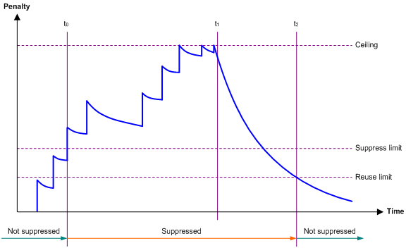
· Penalty—The interface has an initial penalty of 0. When the interface flaps, the penalty increases by 1000 for each down event until the ceiling is reached. It does not increase for up events. When the interface stops flapping, the penalty decreases by half each time the half-life timer expires until the penalty drops to the reuse threshold.
· Ceiling—The penalty stops increasing when it reaches the ceiling.
· Suppress-limit—The accumulated penalty that triggers the device to dampen the interface. In dampened state, the interface does not report its state changes to the CPU. For state change events, the interface only generates SNMP traps and log messages.
· Reuse-limit—When the accumulated penalty decreases to this reuse threshold, the interface is not dampened. Interface state changes are reported to the upper layers. For each state change, the system also generates an SNMP trap and log message.
· Decay—The amount of time (in seconds) after which a penalty is decreased.
· Max-suppress-time—The maximum amount of time the interface can be dampened. If the penalty is still higher than the reuse threshold when this timer expires, the penalty stops increasing for down events. The penalty starts to decrease until it drops below the reuse threshold.
When configuring the dampening command, follow these rules to set the values mentioned above:
· The ceiling is equal to 2(Max-suppress-time/Decay) × reuse-limit. It is not user configurable.
· The configured suppress limit is lower than or equal to the ceiling.
· The ceiling is lower than or equal to the maximum suppress limit supported.
Figure 1 shows the change rule of the penalty value. The lines t0 and t2 indicate the start time and end time of the suppression, respectively. The period from t0 to t2 indicates the suppression period, t0 to t1 indicates the max-suppress-time, and t1 to t2 indicates the complete decay period.
Figure 1 Change rule of the penalty value
Configuration restrictions and guidelines
When you configure dampening on an Ethernet interface, follow these restrictions and guidelines:
· The dampening, link-delay, and port link-flap protect enable commands are mutually exclusive on an interface.
· The dampening command does not take effect on the administratively down events. When you execute the shutdown command, the penalty restores to 0, and the interface reports the down event to the upper-layer protocols.
· Do not enable the dampening feature on an interface with RRPP, MSTP, or Smart Link enabled.
Configuration procedure
To configure dampening on an Ethernet interface:
|
Step |
Command |
Remarks |
|
1. Enter system view. |
system-view |
N/A |
|
2. Enter Ethernet interface view. |
interface interface-type interface-number |
N/A |
|
3. Enable dampening on the interface. |
dampening [ half-life reuse suppress max-suppress-time ] |
By default, interface dampening is disabled on Ethernet interfaces. |
Enabling link flapping protection on an interface
Link flapping on an interface changes network topology and increases the system overhead. For example, in an active/standby link scenario, when interface status on the active link changes between UP and DOWN, traffic switches between active and standby links. To solve this problem, configure this feature on the interface.
With this feature enabled on an interface, when the interface goes down, the system enables link flapping detection. During the link flapping detection interval, if the number of detected flaps reaches or exceeds the link flapping detection threshold, the system shuts down the interface.
Configuration restrictions and guidelines
This feature takes effect only if it is configured in both the system view and interface view.
The dampening, link-delay, and port link-flap protect enable commands are mutually exclusive on an Ethernet interface.
To bring up an interface that has been shut down by link flapping protection, execute the undo shutdown command.
In the display interface command output, the Link-Flap DOWN value of the Current state field indicates that the interface has been shut down by link flapping protection.
Configuration procedure
To enable link flapping protection on an Ethernet interface:
|
Step |
Command |
Remarks |
|
1. Enter system view. |
system-view |
N/A |
|
2. Enable link flapping protection globally. |
link-flap protect enable |
By default, link flapping protection is disabled globally. |
|
3. Enter Ethernet interface view. |
interface interface-type interface-number |
N/A |
|
4. Enable link flapping protection on the Ethernet interface. |
port link-flap protect enable [ interval interval | threshold threshold ] * |
By default, link flapping protection is disabled on an Ethernet interface. |
Enabling loopback testing on an Ethernet interface
Perform this task to determine whether an Ethernet link works correctly.
Loopback testing includes the following types:
· Internal loopback testing—Tests the device where the Ethernet interface resides. The Ethernet interface sends outgoing packets back to the local device. If the device fails to receive the packets, the device fails.
· External loopback testing—Tests the inter-device link. The Ethernet interface sends incoming packets back to the remote device. If the remote device fails to receive the packets, the inter-device link fails.
Configuration restrictions and guidelines
· After you enable this feature on an Ethernet interface, the interface does not forward data traffic.
· The shutdown, port up-mode, and loopback commands are mutually exclusive.
· Enabling loopback testing on an interface will invalidate the voice VLAN, MAC learning limit, MAC address learning, 802.1X, and MAC authentication configurations on the interface. To make these features take effect on the interface, disable loopback testing and configure the features again.
· This feature is used only for debugging and troubleshooting.
Configuration procedure
To enable loopback testing on an Ethernet interface:
|
Step |
Command |
Remarks |
|
1. Enter system view. |
system-view |
N/A |
|
2. Enter Ethernet interface view. |
interface interface-type interface-number |
N/A |
|
3. Enable loopback testing. |
loopback { external | internal } |
By default, loopback testing is disabled on an Ethernet interface. The external keyword is not supported in the current software version. |
Configuring generic flow control on an Ethernet interface
|
|
IMPORTANT: · This feature is not supported on interfaces that operate in half duplex mode. · Enabling or disabling this feature on an interface will cause the interface to go down and then come up. |
To avoid dropping packets on a link, you can enable generic flow control at both ends of the link. When traffic congestion occurs at the receiving end, the receiving end sends a flow control (Pause) frame to ask the sending end to suspend sending packets. Generic flow control includes the following types:
· TxRx-mode generic flow control—Enabled by using the flow-control command. With TxRx-mode generic flow control enabled, an interface can both send and receive flow control frames:
¡ When congestion occurs, the interface sends a flow control frame to its peer.
¡ When the interface receives a flow control frame from its peer, it suspends sending packets to its peer.
· Rx-mode generic flow control—Enabled by using the flow-control receive enable command. With Rx-mode generic flow control enabled, an interface can receive flow control frames, but it cannot send flow control frames:
¡ When congestion occurs, the interface cannot send flow control frames to its peer.
¡ When the interface receives a flow control frame from its peer, it suspends sending packets to its peer.
To handle unidirectional traffic congestion on a link, configure the flow-control receive enable command at one end and the flow-control command at the other end. To enable both ends of a link to handle traffic congestion, configure the flow-control command at both ends.
Configuration restrictions and guidelines
This feature is not supported on 10-GE interfaces operating at 1000 Mbps on the following interface modules:
· FD interface modules: LSQM1GP40TS8FD0, LSQM1TGS24FD0, and LSQM1XPT12TSFD0
· FE interface modules: LSQM1TGS48RFE0
Configuration procedure
To enable generic flow control on an Ethernet interface:
|
Step |
Command |
Remarks |
|
1. Enter system view. |
system-view |
N/A |
|
2. Enter Ethernet interface view. |
interface interface-type interface-number |
N/A |
|
3. Enable generic flow control. |
· Enable TxRx-mode generic flow control: · Enable Rx-mode generic flow control: |
By default, generic flow control is disabled on an Ethernet interface. |
Enabling EEE on an Ethernet interface
With Energy Efficient Ethernet (EEE) enabled, a link-up interface enters low power state if it has not received any packet for a period of time. The time period depends on the chip specifications and is not configurable. When a packet arrives later, the device automatically restores power supply to the interface and the interface restores to the normal state.
Configuration restrictions and guidelines
This feature is supported only on copper ports on the following interface modules:
· FD interface modules:
¡ LSQM1GT48FD0.
¡ LSQM1TGT24FD0.
· SA interface module: LSQM2GT48SA0.
· SC interface modules:
¡ LSQM2GT24PTSSC0.
¡ LSQM2GT24TSSC0.
¡ LSQM4GV48SC0.
· For this feature to take effect on an interface, configure the interface to automatically negotiate a speed or duplex mode with the remote end.
Configuration procedure
To enable EEE on an Ethernet interface:
|
Step |
Command |
Remarks |
|
1. Enter system view. |
system-view |
N/A |
|
2. Enter Ethernet interface view. |
interface interface-type interface-number |
N/A |
|
3. Enable EEE on the Ethernet interface. |
eee enable |
By default, EEE is disabled on an Ethernet interface. |
Setting the statistics polling interval
|
Step |
Command |
Remarks |
|
1. Enter system view. |
system-view |
N/A |
|
2. Enter Ethernet interface view. |
interface interface-type interface-number |
N/A |
|
3. Set the statistics polling interval for the Ethernet interface. |
flow-interval interval |
By default, the statistics polling interval is 300 seconds. |
To display the interface statistics collected in the most recent statistics polling interval, use the display interface command.
Forcibly bringing up a fiber port
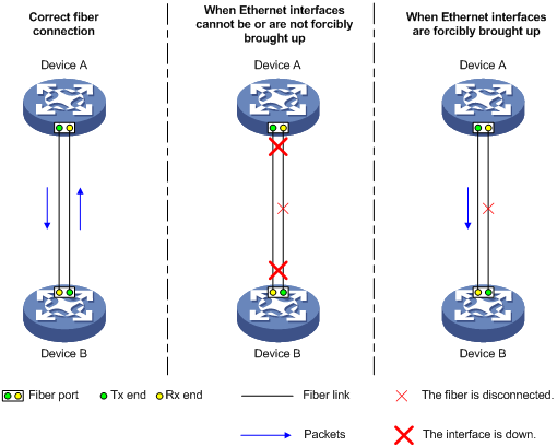
As shown in Figure 2, a GE/10-GE/40-GE/100-GE port uses separate fibers for transmitting and receiving packets. The physical state of the fiber port is up only when both transmit and receive fibers are physically connected. If one of the fibers is disconnected, the fiber port does not work.
To enable a fiber port to forward traffic over a single link, you can use the port up-mode command. This command forcibly brings up a fiber port, even when no fiber links or transceiver modules are present for the fiber port. When one fiber link is present and up, the fiber port can forward packets over the link unidirectionally.
Figure 2 Forcibly bring up a fiber port
Configuration restrictions and guidelines
When you forcibly bring up a fiber port, follow these restrictions and guidelines:
· For fiber ports connected to the same physical link to operate correctly, you must configure this feature for both of them.
· The port up-mode, shutdown, and loopback commands are mutually exclusive.
· A fiber Ethernet port does not support this feature if the port is shut down by a protocol or by using the shutdown command.
· A fiber Ethernet port does not support this feature if the port joins a Layer 2 aggregate group.
· Either of the following operations on an interface forcibly brought up will cause the interface to go down before staying physically up:
¡ Configure the speed and duplex commands on the interface.
¡ Remove and install fibers or transceiver modules.
· A GE fiber port forcibly brought up cannot correctly forward traffic if it is installed with a fiber-to-copper converter, 100/1000-Mbps transceiver module, or 100-Mbps transceiver module. To solve the problem, use the undo port up-mode command on the fiber port.
Configuration procedure
To forcibly bring up a fiber port:
|
Step |
Command |
Remarks |
|
1. Enter system view. |
system-view |
N/A |
|
2. Enter Ethernet interface view. |
interface interface-type interface-number |
Only GE fiber ports, 10-GE fiber ports, 40-GE fiber ports, and 100-GE fiber ports support this feature. Copper ports do not support this feature. |
|
3. Forcibly bring up the fiber port. |
port up-mode |
By default, a fiber port is not forcibly brought up, and the physical state of a fiber port depends on the physical state of the fibers. |
Configuring a Layer 2 Ethernet interface
Configuring storm suppression
The storm suppression feature ensures that the size of a particular type of traffic (broadcast, multicast, or unknown unicast traffic) does not exceed the threshold on an interface. When the broadcast, multicast, or unknown unicast traffic on the interface exceeds this threshold, the system discards packets until the traffic drops below this threshold.
Both storm suppression and storm control can suppress storms on an interface. Storm suppression uses the chip to suppress traffic. Storm suppression has less impact on the device performance than storm control, which uses software to suppress traffic.
Configuration restrictions and guidelines
When you configure storm suppression, follow these restrictions and guidelines:
· For the traffic suppression result to be determined, do not configure storm control together with storm suppression for the same type of traffic. For more information about storm control, see "Configuring storm control on an Ethernet interface."
· The configured suppression threshold value in pps or kbps might be converted into a multiple of a step supported by the chip. As a result, the effective suppression threshold might be different from the configured one. For information about the suppression threshold that takes effect, see the prompt on the device.
Configuration procedure
To set storm suppression thresholds on an Ethernet interface:
|
Step |
Command |
Remarks |
|
1. Enter system view. |
system-view |
N/A |
|
2. Enter Ethernet interface view. |
interface interface-type interface-number |
N/A |
|
3. Enable broadcast suppression and set the broadcast suppression threshold. |
broadcast-suppression { ratio | pps max-pps | kbps max-kbps } |
By default, broadcast suppression is disabled. |
|
4. Enable multicast suppression and set the multicast suppression threshold. |
multicast-suppression { ratio | pps max-pps | kbps max-kbps } |
By default, multicast suppression is disabled. |
|
5. Enable unknown unicast suppression and set the unknown unicast suppression threshold. |
unicast-suppression { ratio | pps max-pps | kbps max-kbps } |
By default, unknown unicast suppression is disabled. |
Configuring storm control on an Ethernet interface
About storm control
Storm control compares broadcast, multicast, and unknown unicast traffic regularly with their respective traffic thresholds on an Ethernet interface. For each type of traffic, storm control provides a lower threshold and an upper threshold.
Depending on your configuration, when a particular type of traffic exceeds its upper threshold, the interface performs either of the following operations:
· Blocks this type of traffic and forwards other types of traffic—Even though the interface does not forward the blocked traffic, it still counts the traffic. When the blocked traffic drops below the lower threshold, the interface begins to forward the traffic.
· Goes down automatically—The interface goes down automatically and stops forwarding any traffic. When the blocked traffic drops below the lower threshold, the interface does not automatically come up. To bring up the interface, use the undo shutdown command or disable the storm control feature.
You can configure an Ethernet interface to output threshold event traps and log messages when monitored traffic meets one of the following conditions:
· Exceeds the upper threshold.
· Drops below the lower threshold.
Both storm suppression and storm control can suppress storms on an interface. Storm suppression uses the chip to suppress traffic. Storm suppression has less impact on the device performance than storm control, which uses software to suppress traffic.
Storm control uses a complete polling cycle to collect traffic data, and analyzes the data in the next cycle. An interface takes one to two polling intervals to take a storm control action.
Configuration restrictions and guidelines
For the traffic suppression result to be determined, do not configure storm control together with storm suppression for the same type of traffic. For more information about storm suppression, see "Configuring storm suppression."
Configuration procedure
To configure storm control on an Ethernet interface:
|
Step |
Command |
Remarks |
|
1. Enter system view. |
system-view |
N/A |
|
2. (Optional.) Set the statistics polling interval of the storm control module. |
storm-constrain interval interval |
The default setting is 10 seconds. For network stability, use the default or set a longer statistics polling interval. |
|
3. Enter Ethernet interface view. |
interface interface-type interface-number |
N/A |
|
4. (Optional.) Enable storm control, and set the lower and upper thresholds for broadcast, multicast, or unknown unicast traffic. |
storm-constrain { broadcast | multicast | unicast } { pps | kbps | ratio } upperlimit lowerlimit |
By default, storm control is disabled. |
|
5. Set the control action to take when monitored traffic exceeds the upper threshold. |
storm-constrain control { block | shutdown } |
By default, storm control is disabled. |
|
6. (Optional.) Enable the Ethernet interface to output log messages when it detects storm control threshold events. |
storm-constrain enable log |
By default, the Ethernet interface outputs log messages when monitored traffic exceeds the upper threshold or drops below the lower threshold after exceeding the upper threshold. |
|
7. (Optional.) Enable the Ethernet interface to send storm control threshold event traps. |
storm-constrain enable trap |
By default, the Ethernet interface sends traps when monitored traffic exceeds the upper threshold or drops below the lower threshold from the upper threshold after exceeding the upper threshold. |
Setting speed options for autonegotiation on an Ethernet interface
About speed options for autonegotiation
By default, speed autonegotiation enables an Ethernet interface to negotiate with its peer for the highest speed that both ends support. You can narrow down the speed option list for negotiation.
Figure 3 Speed autonegotiation application scenario
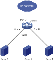
As shown in Figure 3:
· All interfaces on the device are operating in speed autonegotiation mode, with the highest speed of 1000 Mbps.
· Port D provides access to the Internet for the servers.
If the transmission rate of each server in the server cluster is 1000 Mbps, their total transmission rate exceeds the capability of Port D.
To avoid congestion on Port D, configure 100 Mbps as the only option available for speed negotiation on interfaces Port A, Port B, and Port C. As a result, the transmission rate on each interface connected to a server is limited to 100 Mbps.
Configuration restrictions and guidelines
This feature is supported only on GE copper interfaces.
The speed and speed auto commands supersede each other, and whichever is configured last takes effect.
Configuration procedure
To set speed options for autonegotiation on an Ethernet interface:
|
Step |
Command |
Remarks |
|
1. Enter system view. |
system-view |
N/A |
|
2. Enter Ethernet interface view. |
interface interface-type interface-number |
N/A |
|
3. Set speed options for autonegotiation. |
speed auto { 10 | 100 | 1000 } * |
No option is set for speed autonegotiation. |
Setting the MDIX mode of an Ethernet interface
A physical Ethernet interface has eight pins, each of which plays a dedicated role. For example, pins 1 and 2 transmit signals, and pins 3 and 6 receive signals. You can use both crossover and straight-through Ethernet cables to connect copper Ethernet interfaces. To accommodate these types of cables, a copper Ethernet interface can operate in one of the following Medium Dependent Interface-Crossover (MDIX) modes:
· MDIX mode—Pins 1 and 2 are receive pins and pins 3 and 6 are transmit pins.
· MDI mode—Pins 1 and 2 are transmit pins and pins 3 and 6 are receive pins.
· AutoMDIX mode—The interface negotiates pin roles with its peer.
|
|
NOTE: This feature does not take effect on pins 4, 5, 7, and 8 of physical Ethernet interfaces. Pins 4, 5, 7, and 8 of interfaces operating at 1000 Mbps or higher rates receive and transmit signals. |
To enable a copper Ethernet interface to communicate with its peer, set the MDIX mode of the interface by following these guidelines:
· Typically, set the MDIX mode of the interface to AutoMDIX. Set the MDIX mode of the interface to MDI or MDIX only when the device cannot determine the cable type.
· When a straight-through cable is used, configure the interface to operate in an MDIX mode different than its peer.
· When a crossover cable is used, perform one of the following tasks:
¡ Configure the interface to operate in the same MDIX mode as its peer.
¡ Configure either end to operate in AutoMDIX mode.
Configuration restrictions and guidelines
Fiber ports do not support the MDIX mode setting.
Configuration procedure
To set the MDIX mode of an Ethernet interface:
|
Command |
Remarks |
|
|
1. Enter system view. |
system-view |
N/A |
|
2. Enter Ethernet interface view. |
interface interface-type interface-number |
N/A |
|
3. Set the MDIX mode of the Ethernet interface. |
mdix-mode { automdix | mdi | mdix } |
By default, a copper Ethernet interface operates in auto mode to negotiate pin roles with its peer. |
Testing the cable connection of an Ethernet interface
|
|
IMPORTANT: · If the link of an Ethernet interface is up, testing its cable connection will cause the link to go down and then come up. · Fiber ports do not support this feature. · Ethernet copper ports on the LSQM1TGT24FD0 interface module do not support this feature. |
This feature tests the cable connection of an Ethernet interface and displays cable test result within 5 seconds. The test result includes the cable's status and some physical parameters. If any fault is detected, the test result shows the length from the local port to the faulty point.
To test the cable connection of an Ethernet interface:
|
Step |
Command |
|
1. Enter system view. |
system-view |
|
2. Enter Ethernet interface view. |
interface interface-type interface-number |
|
3. Perform a test for the cable connected to the Ethernet interface. |
virtual-cable-test |
Enabling bridging on an Ethernet interface
When a packet arrives at an interface, the switch looks up the destination MAC address of the packet in the MAC address table.
· If the outgoing interface of the entry found is the same as the incoming interface, the switch drops the packet. To enable the switch to forward such packets rather than drop them, enable bridging on the Ethernet interface.
· If no entry is found for the destination MAC address, the switch sends an ARP packet out of all interfaces except the incoming interface. To enable the switch to send the ARP packet out of the incoming interface, enable bridging on the Ethernet interface.
To enable bridging on an Ethernet interface:
|
Step |
Command |
Remarks |
|
1. Enter system view. |
system-view |
N/A |
|
2. Enter Ethernet interface view. |
interface interface-type interface-number |
N/A |
|
3. Enable bridging on the Ethernet interface. |
port bridge enable |
By default, bridging is disabled on an Ethernet interface. |
Configuring a Layer 3 Ethernet interface or subinterface
Setting the MTU for an Ethernet interface or subinterface
The maximum transmission unit (MTU) of an Ethernet interface affects the fragmentation and reassembly of IP packets on the interface. Typically, you do not need to modify the MTU of an interface.
To set the MTU for an Ethernet interface or subinterface:
|
Step |
Command |
Remarks |
|
1. Enter system view. |
system-view |
N/A |
|
2. Enter Ethernet interface or subinterface view. |
interface interface-type { interface-number | interface-number.subnumber } |
N/A |
|
3. Set the MTU of the Ethernet interface or subinterface. |
mtu size |
The default setting is 1500 bytes. |
Displaying and maintaining an Ethernet interface or subinterface
Execute display commands in any view and reset commands in user view.
|
Task |
Command |
|
Display interface traffic statistics. |
display counters { inbound | outbound } interface [ interface-type [ interface-number ] ] |
|
Display traffic rate statistics of interfaces in up state over the last statistics polling interval. |
display counters rate { inbound | outbound } interface [ interface-type [ interface-number ] ] |
|
Display the operational and status information of the specified interfaces. |
display interface [ interface-type [ interface-number | interface-number.subnumber ] ] [ brief [ description | down ] ] |
|
Display information about link flapping protection on interfaces. |
display link-flap protection [ interface interface-type [ interface-number ] ] |
|
Display information about dropped packets on the specified interfaces. |
display packet-drop { interface [ interface-type [ interface-number ] ] | summary } |
|
Display information about storm control on the specified interfaces. |
display storm-constrain [ broadcast | multicast | unicast ] [ interface interface-type interface-number ] |
|
(In standalone mode.) Display the Ethernet module statistics. |
display ethernet statistics slot slot-number |
|
(In IRF mode.) Display the Ethernet module statistics. |
display ethernet statistics chassis chassis-number slot slot-number |
|
Clear interface or subinterface statistics. |
reset counters interface [ interface-type [ interface-number | interface-number.subnumber ] ] |
|
Clear the statistics of dropped packets on the specified interfaces. |
reset packet-drop interface [ interface-type [ interface-number ] ] |
|
(In standalone mode.) Clear the Ethernet module statistics. |
reset ethernet statistics [ slot slot-number ] |
|
(In IRF mode.) Clear the Ethernet module statistics. |
reset ethernet statistics [ chassis chassis-number slot slot-number ] |
