- Table of Contents
- Related Documents
-
| Title | Size | Download |
|---|---|---|
| 01-Text | 8.83 MB |
Contents
Examining the installation site
Installation tools and equipment
Installing cage nuts for attaching mounting brackets
Installing MPUs for the S12516X-AF, S12512X-AF, and S12508X-AF switches
Installing MPUs for the S12504X-AF switch
Installing cable management brackets
Installing switching fabric modules
Installing a filler panel in a switching fabric module slot
Removing a filler panel from a switching fabric module slot
Installing fan trays for the S12516X-AF, S12512X-AF, and S12508X-AF switches
Installing fan trays for the S12504X-AF switch
(Optional) Installing a DC input terminal block
(Optional) Installing transceiver modules
Installing an SFP+/SFP/QSFP+/QSFP28 module
Connecting an SFP+/QSFP+/QSFP28/QSFP+ to SFP+ DAC cable
Viewing switch startup information
Preparing for installation
ESD prevention
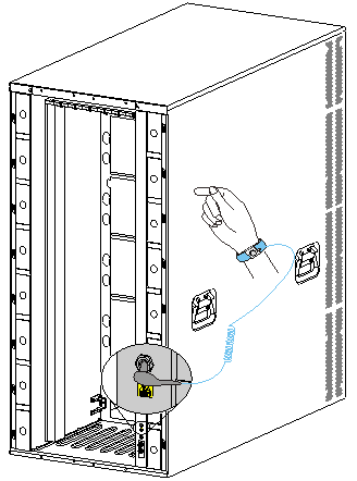
To prevent electronic components from electrostatic discharge (ESD) damage, wear an ESD wrist strap and make sure it makes good skin contact and is reliably grounded before you service the switch or its components.
Figure 1 Attaching an ESD wrist strap (S12516X-AF switch)
|
(1) ESD jack (with an ESD sign) |
Examining the installation site
The switch must be used indoors. To make sure the switch operates correctly and to prolong its service lifetime, the installation site must meet the load-bearing, temperature, humidity, cleanness, EMI, grounding, power supply, ventilation, and space requirements.
As a best practice, reserve a minimum clearance of 1.2 m (3.94 ft) between the switch and walls or other devices.
For more information about the installation site requirements, see H3C S12500X-AF Switch Series Installation Guide.
Installation tools and equipment
No installation tools and equipment are provided with the switch. Prepare them yourself as required.
Installing the switch
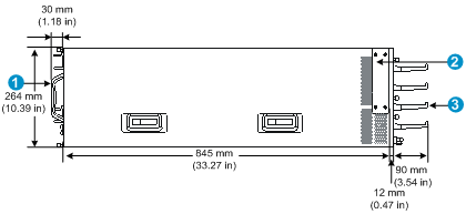
Switch dimensions
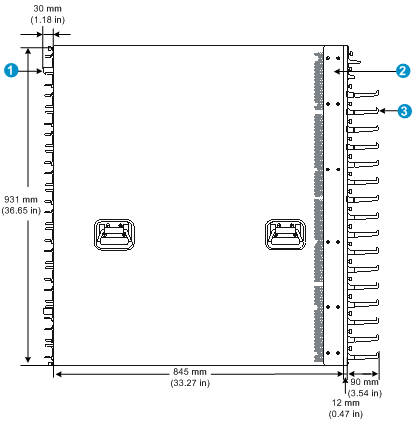
Figure 2 S12516X-AF switch dimensions
|
(1) Fan tray handle |
(2) Mounting bracket |
|
(3) Cable management bracket |
|
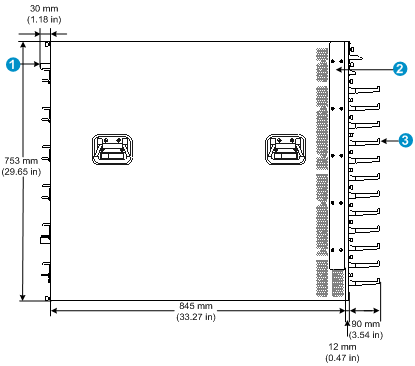
Figure 3 S12512X-AF switch dimensions
|
(1) Fan tray handle |
(2) Mounting bracket |
|
(3) Cable management bracket |
|
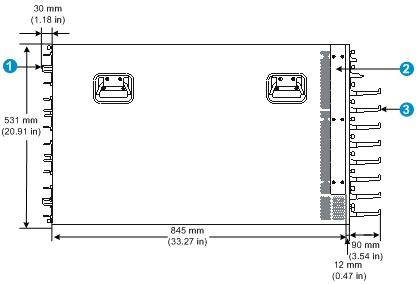
Figure 4 S12508X-AF switch dimensions
|
(1) Fan tray handle |
(2) Mounting bracket |
|
(3) Cable management bracket |
|
Figure 5 S12504X-AF switch dimensions (with the LSXM104XFAN fan trays)
|
(1) Fan tray handle |
(2) Mounting bracket |
|
(3) Cable management bracket |
|
Figure 6 S12504X-AF switch dimensions (with the LSXM104XFANH fan trays)
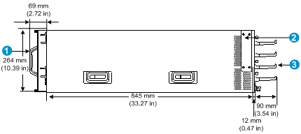
|
(1) Fan tray handle |
(2) Mounting bracket |
|
(3) Cable management bracket |
|
Rack requirements
Table 1 Switch dimensions and rack requirements
|
Model |
Switch dimensions |
Rack requirements |
|
S12516X-AF |
· Height—931 mm (36.65 in) (21 RU) · Width—440 mm (17.32 in) · Total depth—977 mm (38.46 in) ¡ 857 mm (33.74 in) for the chassis ¡ 102 mm (4.02 in) from the rear side of the mounting bracket front ear to the management bracket front end ¡ 30 mm (1.18 in) for the fan tray handle at the rear of the chassis |
· A minimum of 1.1 m (3.61 ft) in depth (recommended.) · A minimum of 130 mm (5.12 in) from the front rack post to the front door. · A minimum of 950 mm (37.40 in) from the front rack post to the rear door. |
|
S12512X-AF |
· Height—753 mm (29.65 in) (17 RU) · Width—440 mm (17.32 in) · Total depth—977 mm (38.46 in) ¡ 857 mm (33.74 in) for the chassis ¡ 102 mm (4.02 in) from the rear side of the mounting bracket front ear to the management bracket front end ¡ 30 mm (1.18 in) for the fan tray handle at the rear of the chassis |
|
|
S12508X-AF |
· Height—531 mm (20.91 in) (12 RU) · Width—440 mm (17.32 in) · Total depth—977 mm (38.46 in) ¡ 857 mm (33.74 in) for the chassis ¡ 102 mm (4.02 in) from the rear side of the mounting bracket front ear to the management bracket front end. ¡ 30 mm (1.18 in) for the fan tray handle at the rear of the chassis |
|
|
S12504X-AF |
· Height—264 mm (10.39 in) (6 RU) · Width—440 mm (17.32 in) · Depth—977 mm (38.46 in) when the LSXM104XFAN fan trays are installed ¡ 857 mm (33.74 in) for the chassis ¡ 102 mm (4.02 in) from the rear side of the mounting bracket front ear to the management bracket front end ¡ 30 mm (1.18 in) for the fan tray handle at the rear of the chassis · Depth—1016 mm (40 in) when the LSXM104XFANH fan trays are installed ¡ 857 mm (33.74 in) for the chassis ¡ 102 mm (4.02 in) from the rear side of the mounting bracket front ear to the management bracket front end ¡ 69 mm (2.72 in) for the fan tray handle at the rear of the chassis |
|
|
NOTE: As a best practice, use a rack that has a single door at the front. |
Slide rail requirements
|
|
IMPORTANT: The switch is heavy. Install the switch at the lowest possible position. |
Before attaching the slide rails, read signs on the slide rails to identify the right and left slide rails and their front and rear ends. Mount the front end of the slide rails to the front rack posts. Make sure the slide rail installation positions are at the same height on the four rack posts.
Table 2 Slide rail requirements
|
Switch model |
Max. chassis weight (full configuration) |
Applicable slide rails |
||
|
Slide rail model |
Adjustment range |
Occupied space |
||
|
S12516X-AF |
400 kg (881.85 lb) |
LSXM1BSR |
630 mm (24.80 in) to 900 mm (35.43 in) |
1 U |
|
S12512X-AF |
300 kg (661.39 lb) |
LSXM1BSR |
630 mm (24.80 in) to 900 mm (35.43 in) |
|
|
LSTM2KSGD0 |
500 mm (19.69 in) to 800 mm (31.50 in) |
2 U |
||
|
S12508X-AF |
220 kg (485.02 lb) |
LSXM1BSR |
630 mm (24.80 in) to 900 mm (35.43 in) |
1 U |
|
LSTM2KSGD0 |
500 mm (19.69 in) to 800 mm (31.50 in) |
2 U |
||
|
S12504X-AF |
120 kg (264.55 lb) |
LSVM1BSR10 |
630 mm (24.80 in) to 850 mm (33.46 in) |
N/A |
|
|
NOTE: · The LSXM1BSR slide rails include a left slide rail, a right slide rail, and a front plate. When attaching the slide rails to the rack, make sure all accessories are correctly installed. · Flanges of the LSVM1BSR10 slide rails are at the bottom so the slide rails do not occupy rack space. |
Installing cage nuts for attaching mounting brackets
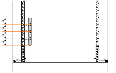
1. As shown in Figure 7, Figure 8, Figure 9, and Figure 10, determine the cage nut installation holes and then mark them on the front rack post.
2. Install cage nuts in the marked square holes on the front rack posts.
For the S12516X-AF, S12512X-AF, and S12508X-AF switches, cage nuts are not needed for the top two marked square holes on the right front rack post.
For the S12504X-AF switch, install cage nuts in all the marked square holes.
Figure 7 Installing cage nuts (for the S12516X-AF switch)
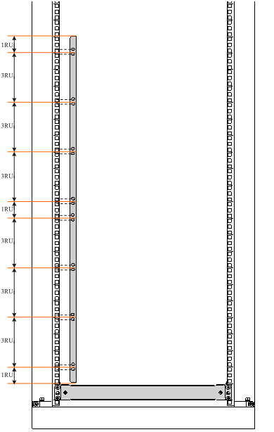
Figure 8 Installing cage nuts (for the S12512X-AF switch)
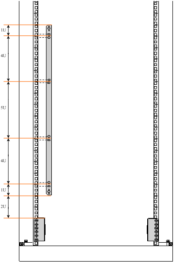
Figure 9 Installing cage nuts (for the S12508X-AF switch)
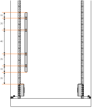
Figure 10 Installing cage nuts (for the S12504X-AF switch)
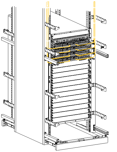
Mounting the switch in a rack
|
|
CAUTION: · Remove fan trays, power modules, and filler panels from the switch before moving if you lift the switch manually. Reinstall these components after installing the switch in the rack. · Do not hold the handle of a fan tray, a power module, or a card, or the air vents of the chassis to move the switch. Any attempt to carry the switch with these parts might cause equipment damage or even bodily injury. · After you place the switch on the slide rails, do not leave go of your hands immediately because this might tip the switch, damaging the switch or even causing bodily injury. |
To mount the switch in the rack:
1. Face the rear of the chassis towards the front of the rack.
2. Use a minimum of four people to move the switch by holding the chassis handles.
As a best practice, use a mechanical lift to lift the switch.
3. Place the switch on the slide rails from the front of the rack and slide the switch along the guide rails until the mounting brackets on the switch touch the front rack posts tightly, as shown by callout 2 in Figure 11.
4. Use screws provided with the switch to attach the mounting brackets to the rack posts.
For the S12516X-AF, S12512X-AF, and S12508X-AF switches, the name plate on the upper right corner of the front panel covers two mounting screw holes on the mounting brackets. Screws are not needed for these two mounting holes.
If the mounting holes in the mounting brackets cannot align with the cage nuts on the rack, verify the following items:
¡ The bottom edge of the slide rail aligns with the middle of the narrower metal area between holes.
¡ The cage nuts are installed in the correct holes.
Figure 11 Mounting the S12516X-AF switch in the rack
|
(1) Chassis handle |
(2) Slide the chassis into the rack |
|
(3) Use screws to secure the mounting brackets to the rack |
|
Grounding the switch
|
|
CAUTION: · Grounding the switch reliably is crucial to lightning protection and EMI protection. Ground the switch reliably before you use it. · Use the grounding cable (yellow-green grounding cable) provided with the switch. · Connect the grounding cable to the earthing system in the equipment room. Do not connect it to a fire main or lightning rod. |
To connect the grounding cable to a grounding strip:
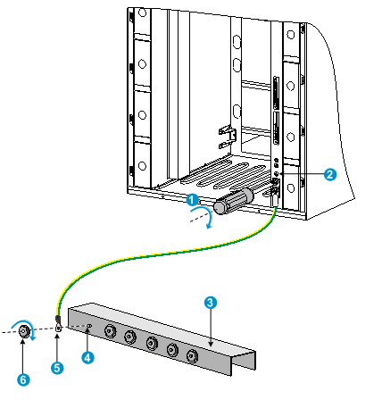
1. Unpack the grounding cable.
The grounding cable provided with the switch is compliant with the NEBS standards. The two-hole grounding lug of the grounding cable is used for connecting the chassis. The ring terminal of the grounding cable is used for connecting the grounding strip.
2. Remove the grounding screws from the grounding holes at the rear of the chassis.
A grounding sign is provided with the grounding holes, as shown by callout 2 in Figure 12.
3. Use grounding screws to attach the two-hole grounding lug of the grounding cable to the chassis.
Figure 12 Connecting the grounding cable to a grounding strip (S12516X-AF switch)
|
(1) Use the grounding screws to attach the two-hole grounding lug to the grounding point |
||
|
(2) Grounding sign |
(3) Grounding strip |
(4) Grounding post |
|
(5) Ring terminal |
(6) Hex nut |
|
Installing FRUs
This section describes the installation procedures for the MPUs, LPUs, switching fabric modules, fan trays, and power modules. For the compatibility matrix between these modules and the switch models, see H3C S12500X-AF Switch Series Installation Guide.
|
|
WARNING! Long-time exposure to strong air flow might cause discomfort. As a best practice, do not stand close to the air outlet vents while the switch is operating. If you must be next to the switch on the air outlet vent side for an extended period, avoid the air flow or take other protective measures. |
|
|
CAUTION: For good ventilation of the switch, install filler panels in empty FRU slots. |
Attaching an ESD wrist strap
To prevent electronic components from ESD damage, wear an ESD wrist strap and make sure it makes good skin contact and is reliably grounded before you install FRUs. See Figure 1 for attaching an ESD wrist strap.
Installing MPUs
|
|
CAUTION: · If you are not to install an MPU in an MPU slot, keep the filler panel in the slot. · When you install an MPU, avoid damaging the connectors on the MPU. · To prevent a filler panel from being drawn into the chassis when fan speed is high, use both hands to grasp the filler panel by its two sides during filler panel installation and removal on an operating switch. |
Unless otherwise stated, the term "MPU" in this document refers to MPUs and cloud SEUs.
You can install one MPU, or two MPUs for redundancy on the switch. If you are to install one MPU, install it in either of the MPU slots.
Installing MPUs for the S12516X-AF, S12512X-AF, and S12508X-AF switches
For the S12516X-AF, S12512X-AF, and S12508X-AF switches, the ejector levers of the MPUs and the ejector lever seats on the MPU slots have pink marks. The MPU installation procedure is the same for the S12516X-AF, S12512X-AF, and S12508X-AF switches. The following uses the S12516X-AF switch as example.
To install an MPU:
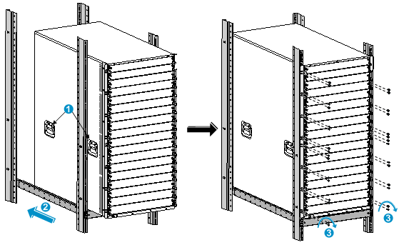
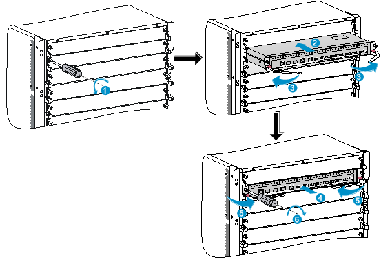
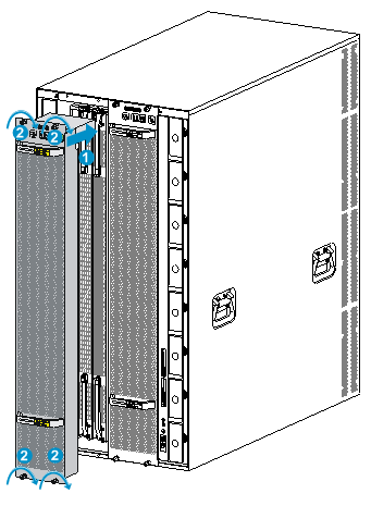
1. As shown by callout 1 in Figure 13, remove the filler panel from the target MPU slot.
Keep the removed filler panel secure for future use.
2. As shown by callout 2 in Figure 13, orient the MPU with the lettering on it upright. Hold the MPU by the front panel with one hand and support the bottom with the other. Push the MPU steadily into the slot along the guide rails.
Keep the MPU parallel to the slot to avoid touching other components in the chassis.
3. As shown by callout 3 in Figure 13, pull the ejector levers of the MPU outward when most part of the MPU is inserted in the slot.
4. Push the MPU until the brakes on its ejector levers touch the slot edges tightly.
5. As shown by callout 4 in Figure 13, continue to push the MPU by its middle part on the front panel until you cannot move it.
6. As shown by callout 5 in Figure 13, push the ejector levers inward until they come in close contact with the front panel.
7. As shown by callout 6 in Figure 13, fasten the captive screws on the MPU.
Figure 13 Installing an MPU (S12516X-AF switch)
|
(1) Loosen the captive screws and remove the filler panel |
|
|
(2) Insert the MPU into the slot |
(3) Pull the ejector levers outward |
|
(4) Push the MPU by the middle part on the front panel |
|
|
(5) Pull the ejector levers inward |
(6) Fasten the captive screws |
Installing MPUs for the S12504X-AF switch
The S12504X-AF switch MPU marks and MPU slot edges are pink-marked.
To install an MPU for the S12504X-AF switch:
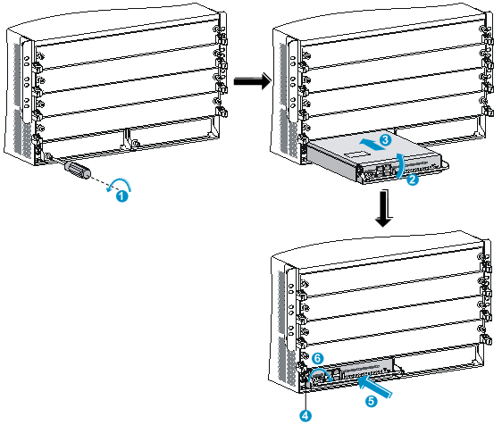
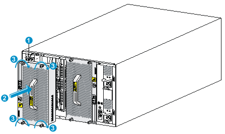
1. As shown by callout 1 in Figure 14, remove the filler panel from the target MPU slot.
Keep the removed filler panel secure for future use.
2. As shown by callout 2 in Figure 14, pivot up the handle of the MPU.
3. As shown by callout 3 in Figure 14, orient the MPU with lettering on it upright. Hold the MPU by the front panel with one hand and support the bottom with the other. Push the MPU steadily into the slot along the guide rails.
Keep the MPU parallel to the slot to avoid touching other components in the chassis.
4. As shown by callout 4 in Figure 14, push the MPU until the handle breaks touch the slot edges tightly.
5. As shown by callout 5 in Figure 14, continue to push the MPU handle until the MPU is secure in position.
6. Fasten the captive screws on the MPU.
Figure 14 Installing an MPU (S12504X-AF switch)
|
(1) Loosen the captive screws and remove the filler panel |
|
(2) Pivot up the handle |
|
(3) Push the MPU into the slot along the guide rails |
|
(4) Push the MPU until the handle breaks touch the slot edges tightly |
|
(5) Push the handle until the MPU is secure in position |
|
(6) Fasten the screws on the MPU |
Installing LPUs
|
|
CAUTION: To prevent a filler panel from being drawn into the chassis when fan speed is high, use both hands to grasp the filler panel by its two sides during filler panel installation and removal on an operating switch. |
|
|
CAUTION: To prevent card damage and ensure correct operation, LPUs can only be used with switching fabric modules of the same type. · Type T LPUs have a character T in their card identifier (for example, LSXM1CGQ36TD1). Type T switching fabric modules have a character string of SFT in their card identifier (for example, LSXM1SFT16E1). · Type H LPUs have a character of H in their card identifier (for example, LSXM1CGQ36HB1). Type H switching fabric modules have a character string of SFH in their card identifiers (for example, LSXM1SFH16C1). · Type F LPUs have a character of F in their card identifier (for example, LSXM1CGP12FX1). Type F switching fabric modules have a character string of SFF in their card identifiers (for example, LSXM1SFF16C1). |
Installing S12500-X LPUs
|
|
CAUTION: For heat dissipation of the switch, you must install an LPU in the slot where an interface module adapter is installed. If you are not to install an LPU in the slot, remove the interface module adapter and install a filler panel. |
The S12500-X LPUs with the dimensions 39.8 × 399.2 × 512.1 mm (1.57 × 15.72 × 20.16 in) are available for the switch. To install an S12500-X LPU on the switch, first install an interface module adapter in the LPU slot.
Installing an interface module adapter
1. Remove the filler panel from the target slot. See callout 1 in Figure 13.
Keep the removed filler panel secure for future use.
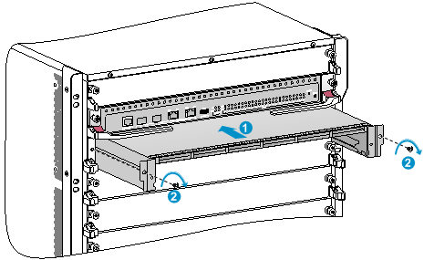
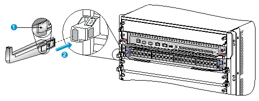
2. As shown in Figure 15, align the adapter rear with the LPU slot and push the adapter slowly along the guide rails into the slot.
3. As shown by callout 2 in Figure 15, use the screws provided with the interface module adapter to secure the adapter to the chassis.
Figure 15 Installing an interface module adapter (S12516X-AF switch)
|
(1) Push the interface module adapter slowly along the guide rails into the slot |
|
(2) Fasten the screws to secure the interface module adapter to the chassis |
Installing an S12500-X LPU
The S12500-X LPU edges and the ejector lever seats on the LPU slots have purple marks.
To install an S12500-X LPU:
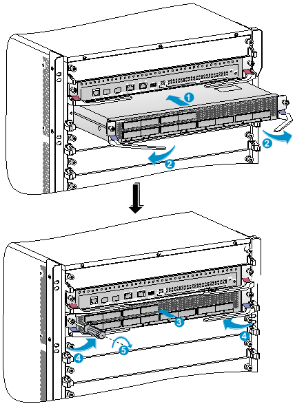
1. As shown in Figure 16, loosen the captive screws that secure the LPU to the protection box, pull the ejector levers of the LPU outward, and pull out the LPU from the protection box.
2. Hold the LPU by the front panel with one hand and support its bottom with the other. Slide the LPU steadily into the target slot along the guide rails with the PCB facing up. Do not touch the components on the PCB. See Figure 17.
Keep the LPU parallel to the slot to avoid touching other components in the chassis.
3. As shown by callout 2 in Figure 17, pull the ejector levers outward when most of the LPU is inserted into the slot.
4. Push the LPU until the brakes on its ejector levers touch the slot edges tightly.
5. As shown by callout 3 in Figure 17, continue to push the LPU by its middle part on the front panel until you cannot move it.
6. As shown by callout 4 in Figure 17, push the ejector levers inward until they come in close contact with the panel.
7. As shown by callout 5 in Figure 17, fasten the captive screws to secure the LPU to the interface module adapter.
Figure 16 Removing an S12500-X LPU from the protection box
|
(1) Loosen the captive screws that secure the LPU to the protection box |
|
|
(2) Pull the ejector levers outward |
(3) Pull the LPU out of the protection box |
Figure 17 Installing an S12500-X LPU (S12516X-AF switch)

|
(1) Push the LPU slowly along the guide rails into the slot |
(2) Pull the ejector levers outward |
|
(3) Push the LPU by the middle part on the front panel |
(4) Pull the ejector levers inward |
|
(5) Fasten the captive screws on the LPU |
|
Installing S12500X-AF LPUs
|
|
CAUTION: Install filler panels in the empty LPU slots. |
The S12500X-AF LPUs available for the switch have a height of 50 mm (1.97 in), a width of 433 mm (17.05 in), and a depth that varies by LPU model. No interface module adapter is required to install an S12500X-AF LPU on the switch.
The S12500X-AF LPU ejector levers and the ejector lever seats on the LPU slots have purple marks.
Installing an LPU with common ejector levers
1. Remove the filler panel from the target LPU slot.
The filler panel removal procedure is the same for LPU and MPU slots. You can see callout 1 in Figure 13 for reference.
Keep the removed filler panel secure for future use.
2. As shown by Figure 18, orient the LPU with the lettering on it upright. Hold the LPU by the front panel with one hand and support the bottom with the other. Push the LPU steadily into the slot along the guide rails.
Keep the LPU parallel to the slot to avoid touching other components in the chassis.
3. As shown by callout 2 in Figure 18, pull the ejector levers of the LPU outward when most part of the LPU is inserted in the slot.
4. Push the LPU until the brakes on its ejector levers touch the slot edges tightly.
5. As shown by callout 3 in Figure 18, continue to push the LPU by its middle part on the front panel until you cannot push it further.
6. As shown by callout 4 in Figure 18, push the ejector levers inward until they come in close contact with the front panel.
7. As shown by callout 5 in Figure 18, fasten the captive screws on the LPU.
Figure 18 Installing an S12500X-AF LPU (S12516X-AF switch)
|
(1) Push the LPU slowly along the guide rails into the slot |
(2) Pull the ejector levers outward |
|
(3) Push the LPU by the middle part on the front panel |
(4) Pull the ejector levers inward |
|
(5) Fasten the captive screws on the LPU |
|
Installing an LPU with foldable ejector levers
1. Orient the LPU with the lettering on it upright.
2. As shown by callout 1 in Figure 19, holding the LPU by the front panel with one hand and supporting its bottom with the other, slide the LPU gently into the slot along the slide rails.
Keep the LPU parallel to the slot to avoid damaging other components in the chassis.
3. When most part of the LPU is inserted into the slot, simultaneously pivot the ejector levers towards each other until they stop, as shown by callout 2 in Figure 19.
4. As shown by callout 3 in Figure 19, rotate the ejector levers away from the front panel until they stop.
5. As shown by callout 4 in Figure 19, push the LPU by its middle part on the front panel until you cannot move it.
6. As shown by callout 5 in Figure 19, push the ejector levers inward towards the front panel.
7. As shown by callout 6 in Figure 19, fasten the captive screws to secure the LPU in the chassis.
8. As shown by callout 7 in Figure 19, rotate the ejector levers upward to the vertically closed position.
Figure 19 Installing an LPU with foldable ejector levers (S12516X-AF switch)

|
(1) Push the LPU slowly into the slot along the slide rails |
|
(2) Rotate the ejector levers towards each other until they stop |
|
(3) Rotate the ejector levers away from the front panel until they stop |
|
(4) Push the LPU by the middle part on the front panel |
|
(5) Push the ejector levers inward towards the front panel |
|
(6) Fasten the captive screws on the LPU |
|
(7) Rotate the ejector levers upward to the vertically closed position |
Installing cable management brackets
The cable management brackets are installed on the two sides of the LPU slots. As a best practice, install cable management brackets after you have installed LPUs.
As shown in Figure 20, insert the cable management bracket end that has a spring tab into the cable management bracket hole until the bracket has close contact with the hole.
Figure 20 Installing a cable management bracket (S12516X-AF switch)
|
(1) Spring tab on the cable management bracket |
|
(2) Align the cable management bracket with the bracket hole |
|
|
NOTE: You must press the spring tab while you are removing a cable management bracket. |
Installing switching fabric modules
|
|
CAUTION: · When you install a switching fabric module, avoid damaging the connectors on it. · Fan trays cover switching fabric module slots. Before installing a fan tray, install switching fabric modules or filler panels in the switching fabric module slots the fan tray covers. · To replace or install switching fabric modules in the slots covered by both fan trays when the switch is operating, do not remove both fan trays at the same time. Remove one fan tray to replace or install switching fabric modules in slots covered by the fan tray, and then reinstall the fan tray. You can remove the other fan tray only after this fan tray operates correctly. · The smart speed adjustment feature increases the fan speed when only one fan tray is operating. Take noise protection measures such as wearing an earmuff or earplug. In addition, make good preparation before hot swapping a switching fabric module to minimize the operation time. |
|
|
CAUTION: The S12516X-AF, S12512X-AF, S12508X-AF, and S12504X-AF switches use slots 18 to 23, 14 to 19, 10 to 15, and 6 to 11 for switching fabric modules, respectively. · To use an LSXM1TGS24FX1 LPU, the three lowest-numbered switching fabric module slots take precedence over other slots for module installation. For an LSXM1TGS24FX1 LPU to start up correctly, install a minimum of one switching fabric modules in the three lowest-numbered switching fabric module slots. · To use an LSXM1TGS48C2HB1, LSXM1TGS48HB1, LSXM1TGS48HF1, LSXM1CGQ6QGHB1, LSXM1CGQ6QGHF1, or LSXM1TGS24QGMODHB1 LPU, the three highest-numbered switching fabric module slots take precedence over other slots for module installation. For the LPU to start up correctly, install a minimum of one switching fabric modules in the three highest-numbered switching fabric module slots. · To use an LSXM1QGS24HB1, LSXM1QGS36HB1, LSXM1TGS48QGHA1, or LSXM1TGS24CGMODHD1 LPU, the four highest-numbered switching fabric module slots take precedence over other slots for module installation. For the LPU to start up correctly, install a minimum of one switching fabric modules in the four highest-numbered switching fabric module slots. |
|
|
CAUTION: To prevent card damage and ensure correct operation, switching fabric modules can only be used with LPUs of the same type. · Type T switching fabric modules have a character string of SFT in their card identifier (for example, LSXM1SFT16E1). Type T LPUs have a character of T in their card identifier (for example, LSXM1CGQ36TD1). · Type H switching fabric modules have a character string of SFH in their card identifier (for example, LSXM1SFH16C1). Type H LPUs have a character of H in their card identifier (for example, LSXM1CGQ36HB1). · Type F switching fabric modules have a character string of SFF in their card identifier (for example, LSXM1SFF16C1). Type F LPUs have a character of F in their card identifier (for example, LSXM1CGP12FX1). |
The switch comes with all switching fabric module slots empty. Purchase switching fabric modules and filler panels for the switching fabric module slots as required.
To install a switching fabric module:
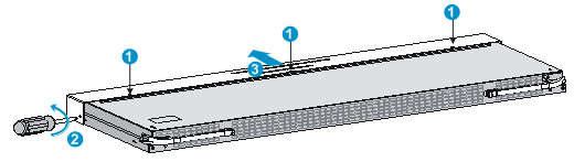
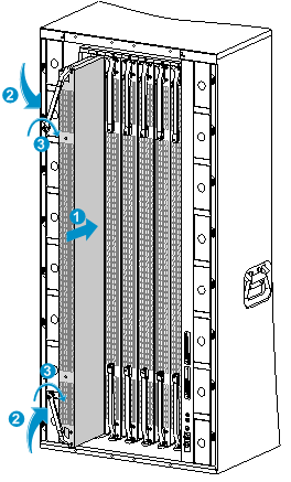
1. Place the switching fabric module on a workbench and remove the protection box from the connector side of the switching fabric module. See Figure 21.
2. Release the ejector levers by pressing the spring clips.
3. Orient the switching fabric module with the side marked "Up" facing up. Hold the switching fabric module front panel near the ejector levers with one hand and support the module bottom with the other. Place the module bottom on the bottom guide rails of the chassis. Align the switching fabric module with the target slot and insert it into the slot along the guide rails. See callout 1 in Figure 22.
Keep the module parallel to the slot to avoid touching other components in the chassis.
4. As shown by callout 2 in Figure 22, continue to push the switching fabric module until the brakes on its ejector levers touch the slot edges tightly. Simultaneously rotate the ejector levers inward until the spring clips lock the ejector levers in place and the switching fabric module is completely seated in the slot.
Figure 21 Removing the switching fabric module from the protection box (S12516X-AF switching fabric module)
|
(1) Five screws to secure the protection box to the switching fabric module |
(2) Loosen the captive screws |
|
(3) Hold the protection box to disengage it from the connector side of the switching fabric module |
|
Figure 22 Installing a switching fabric module (S12516X-AF switch)
|
(1) Push the switching fabric module slowly into the slot |
|
(2) Rotate the ejector levers inward until the spring clips lock the ejector levers in place |
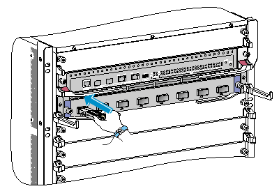
Installing a filler panel in a switching fabric module slot
The switch comes with empty switching fabric module slots. Install a filler panel in a switching fabric module slot if you are not to install a switching fabric module in it.
To install a filler panel in a switching fabric module slot:
1. Loosen the captive screws on the ejector levers and rotate outward the ejector levers.
2. Orient the filler panel with the side marked "Up" facing up. Hold the filler panel front panel near the ejector levers with one hand and support its bottom with the other. Place the filler panel bottom gently on the bottom guide rails of the chassis. Align the filler panel with the switching fabric module slot. Push the filler panel slowly into the slot along the guide rails. See callout 1 in Figure 23.
Keep the filler panel parallel to the switching fabric module slot to avoid touching other components in the chassis.
3. As shown by callout 2 in Figure 23, continue to push the filler panel until the brakes on its ejector levers touch the slot edges tightly. Simultaneously rotate the ejector levers inward.
4. Fasten the captive screws on the ejector levers.
Figure 23 Installing a filler panel in a switching fabric module slot (S12516X-AF switch)
|
(1) Push the filler panel slowly into the slot |
(2) Simultaneously rotate the ejector levers inward |
|
(3) Fasten the captive screws on the ejector levers |
|
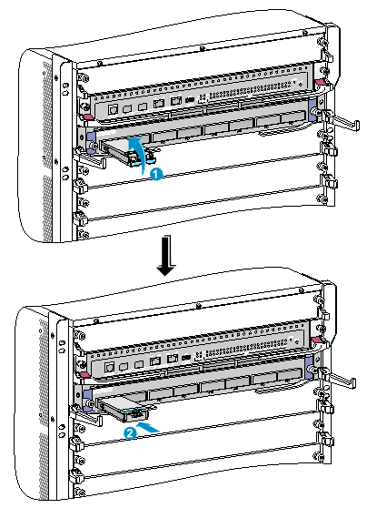
Removing a filler panel from a switching fabric module slot
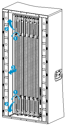
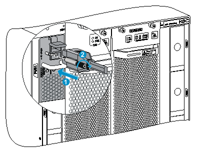
1. As shown by callout 1 in Figure 24, loosen the captive screws on the ejector levers.
2. As shown by callout 2 in Figure 24, rotate outward the ejector levers. Then pull the filler panel part way out of the slot.
3. As shown by callout 3 in Figure 24, hold the filler panel by the top and bottom edges to pull the filler panel out of the slot.
Keep the removed the filler panel secure for future use.
Figure 24 Removing the filler panel from a switching fabric module slot (S12516X-AF switch)
|
(1) Loosen the captive screws on the ejector levers |
(2) Rotate the ejector levers outward |
|
(3) Pull the filler panel out of the slot along the guide rails |
|
Installing fan trays
Follow these restrictions and guidelines when you install a fan tray:
· Install the switching fabric modules or filler panels in the switching fabric module slots before you install a fan tray.
· The switch has two fan tray slots: FAN1 and FAN2. One fan tray is sufficient for heat dissipation of the switch. As a best practice, install two fan trays on the switch for redundancy and noise reduction.
· The fan tray is hot swappable. Follow these guidelines when you hot swap a fan tray:
¡ Ensure electricity safety.
¡ Replace a fan tray only when the other fan tray is operating correctly.
¡ To prevent dust from entering the chassis, keep the failed fan tray in position before the replacement.
· When you hot swap a fan tray, only one fan tray is operating and it automatically increases the fan rotation speed and makes louder noise. Take protection measures such as wearing an earmuff or earplug. In addition, make good preparation before the hot swapping to minimize the operation time.
Installing fan trays for the S12516X-AF, S12512X-AF, and S12508X-AF switches
|
|
IMPORTANT: The fan tray is high and heavy. To avoid device damage and bodily injury, use two people to install or remove a fan tray. |
To install a fan tray for the S12516X-AF/S12512X-AF/S12508X-AF switch:
1. Orient the fan tray with the upside up based on the orientation of characters on the fan tray and align the fan tray with the fan tray slot.
2. Holding the upper fan tray handle with one hand and the lower fan tray handle with the other hand, insert the fan tray into the slot. Keep the fan tray as straight as possible.
To install a fan tray in FAN1 slot, align the top and left edges of the fan tray in the slot. To install a fan tray in FAN2 slot, align the top and right edges of the fan tray in the slot.
3. Fasten the captive screws on the fan tray.
Figure 25 Installing a fan tray (S12516X-AF switch)
|
(1) Align the fan tray with the fan tray slot |
(2) Fasten the captive screws |
Installing fan trays for the S12504X-AF switch
1. Orient the fan tray correctly.
To install a fan tray in the FAN1 slot, orient the fan tray so that the LEDs are on the left side of the front panel. To install a fan tray in the FAN2 slot, orient the fan tray so that the LEDs are on the right side of the front panel.
2. As shown by callout 1 in Figure 26Figure 26, align the positioning pin on the fan tray with the positioning hole in the chassis.
3. As shown by callout 2 in Figure 26, hold the fan tray handle and insert the fan tray into the slot.
Keep the fan tray as straight and stable as possible while inserting it into the slot.
4. As shown by callout 3 in Figure 26, fasten the captive screws on the fan tray.
Figure 26 Installing a fan tray for the S12504X-AF switch
|
(1) Align the positioning pin on the fan tray with the positioning hole in the chassis |
|
|
(2) Insert the fan tray into the chassis |
(3) Fasten the captive screws on the fan tray |
Installing power modules
The power module slots are located at the two sides of the rear panel.
The installation procedure is the same for DC and AC power modules.
To install a power module:
1. If a filler panel is installed in the slot, remove the filler panel first.
¡ For a filler panel as shown in Figure 27, thread a flat-blade screwdriver through the hole in the handle of the filler panel and pull the filler panel out.
¡ For a filler panel as shown in Figure 28, use your forefinger to hold the filler panel through the hole and pull out the filler panel along the guide rails.
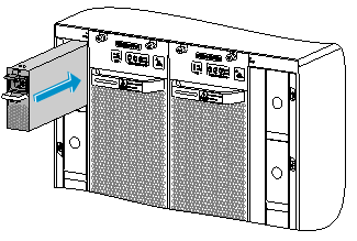
2. Correctly orient the power module.
If you install the power module in a left power module slot, make sure the latch is above the handle. If you install the power module in a right power module slot, make sure the latch is below the handle.
3. Holding the handle of the power module with one hand and supporting the bottom of the power module with the other, slide the power module along the guide rails into the slot until you hear a click.
The power module is foolproof. If the power module is oriented incorrectly, you cannot install the power module into the slot. If you encounter a hard resistance while inserting the power module, pull out the power module, reorient it, and then insert it again.
Figure 27 Removing a filler panel (1)
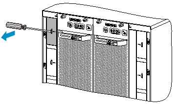
Figure 28 Removing a filler panel (2)
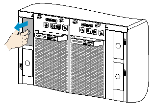
Figure 29 Installing a power module (S12516X-AF switch)
Connecting the power cord
|
|
CAUTION: · Power on the switch after you have installed fan trays on the switch. · Make sure each power cord has a separate circuit breaker. · Turn off the circuit breaker before you connect the power cord. |
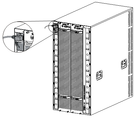
Connecting an AC power cord
1. Plug the AC power cord connector into the AC input receptacle of the power module.
2. Use a removable cable tie or self-adhesive cable tie (provided with the power module) to secure the power cord to the handle of the power module.
3. Plug the other end of the power cord into an AC power receptacle, and turn on the circuit breaker.
Figure 30 Using a removable cable tie to secure the power cord to the switch (S12516X-AF switch)
Connecting a DC power cord
To connect a DC power cord:
1. Connect the DC power cord connector to the DC-input receptacle on the power module.
2. Fasten the screw on the connector to secure the DC power cord in place.
3. Connect the other end of the DC power cord to the source terminal block:
Figure 31 Connecting the DC power cord
(Optional) Installing a DC input terminal block
You can order an extension cable and a DC input terminal block to supply power to the device if the following situations exist:
· The power distribution box is far away from the rack.
· The power cord size does not apply to the power distribution box.
· Terminals on the power distribution box do not support customization.
A DC input terminal block provides eight pairs of terminals.Each pair provides one power line reconnection. A maximum of eight DC power line reconnections are supported. The terminals support a wire with a size of 10 mm² to 35 mm² (0.02 sq.in to 0.05 sq.in).
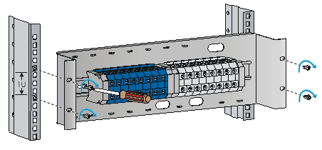
To attach a DC input terminal block to a rack:
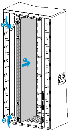
1. Install cage nuts on the rack posts.
2. Use screws to attach the DC input terminal block to the rack.
Figure 32 Attaching a DC input terminal block to a rack
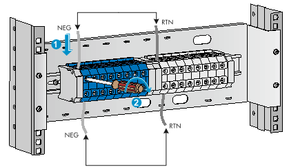
To connect power wires to a DC input terminal block:
1. As shown in Figure 33, insert the wires of the extension cable into the upper-row terminals on the DC input terminal block, and insert the other ends of the wires into the terminals on the power distribution cabinet.
2. Insert the wires of the DC power cord into the lower-row terminals on the DC input terminal block, and insert the other ends of the wires into the terminal block on the switch.
Figure 33 Connecting wires to a DC input terminal block
(Optional) Installing transceiver modules
|
|
CAUTION: · To prevent particles from entering the ports, keep the dust plugs in the SFP+/SFP ports if you are not to install transceiver modules or cables in the ports. · To prevent particles from entering the ports, install the dust plugs that come with the LPUs in the QSFP+/CXP/CFP2/QSFP28 ports if you are not to install transceiver modules or cables in the ports. |
Installing an SFP+/SFP/QSFP+/QSFP28 module
|
|
CAUTION: · Read the following instructions before you install an SFP+/SFP/QSFP+/QSFP28 module. Failure to follow these instructions might cause damage to the module. · Do not remove the dust plug from the SFP+/SFP/QSFP+/QSFP28 module if you are not to connect an optical fiber to the module. · Before you install an SFP+/SFP/QSFP+/QSFP28 module, remove the optical fiber (if any) from it. |
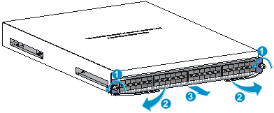
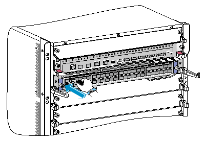
To install an SFP+/SFP/QSFP+/QSFP28 module:
1. Unpack the module.
Do not touch the golden plating of the module.
2. Pivot the clasp of the module up. Holding the module, gently push the module into the slot until it has firm contact with the slot, as shown in Figure 34.
¡ For a module that uses a plastic pull latch, skip this step.
¡ For an SFP+ module, press the module down so you can push the module straight into the port.
¡ If you cannot hold the module by its two sides because of high module density, press the module on its head end to push it in.
Figure 34 Installing an SFP+/SFP/QSFP+/QSFP28 module (S12516X-AF switch)
Installing a CFP2 module
|
|
CAUTION: · Read the following instructions before you install a CFP2 module. Failure to follow these instructions might cause damage. · Before you install or remove a CFP2 module, remove the optical fiber (if any) from it. |
To install a CFP2 module:
1. Unpack the CFP2 module.
Do not touch the golden plating of the module.
2. Pivot the module handle up.
3. Correctly orient the CFP2 module and make sure the module handle is on top of the CFP2 module. Gently push the module into the slot until it clicks into place.
Figure 35 Installing a CFP2 module (S12516X-AF switch)
|
(1) Pivot up the metal handle |
(2) Push the module gently into the slot |
Installing a CXP module
|
|
CAUTION: · Read the following instructions before you install a CXP module. Failure to follow these instructions might cause damage to the CXP module. · Do not remove the dust plug from the CXP module until you are ready to connect an optical fiber to the module. · Before you install a CXP module, remove the optical fiber (if any) from it. |
CXP modules are available in two types. One type is with a rubber pull latch and the other is with a plastic pull latch.
The installation and removal procedures are the same for the CXP modules with a rubber or plastic pull latch. This guide uses the CXP module with a plastic pull latch as an example.
To install a CXP module:
1. Unpack the CXP module.
Do not touch the golden plating of the module.
2. Correctly orient the CXP module and make sure the pull latch is on top of the CXP module. Gently push the module into the slot until it has firm contact with the slot.
Figure 36 Installing a CXP module (S12516X-AF switch)
Connecting an SFP+/QSFP+/QSFP28/QSFP+ to SFP+ DAC cable
|
|
CAUTION: When you connect a fiber cable, make sure the bend radius of the cable is no less than eight times the fiber diameter. |
The cables are hot swappable.
Use SFP+ DAC cables to connect SFP+ ports, QSFP+ DAC cables to connect QSFP+ ports, QSFP28 DAC cables to connect QSFP28 ports, and QSFP+ to SFP+ DAC cables to connect QSFP+ and SFP+ ports.
To connect an SFP+/QSFP+/QSFP28/QSFP+ to SFP+ DAC cable:
1. Unpack the cable.
2. Plug the cable connector into the port. Make sure the cable connector is correctly oriented.
Cabling recommendations
Routing network cables
The cable management brackets are installed on the two sides of the LPU section. As a best practice, route network cables from the left and right sides, as shown in Figure 37.
Figure 37 Routing network cables (S12516X-AF switch)
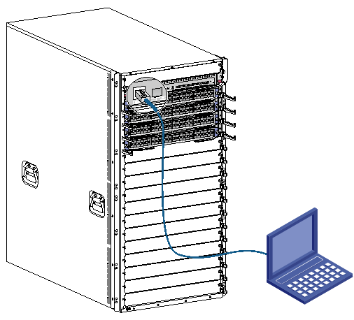
Accessing the switch
The first time you access the switch you must use a console cable to connect a console terminal, for example, a PC, to the console port on the switch.
Connecting the console cable
|
|
IMPORTANT: · Identify the mark on the console port and make sure you are connecting to the correct port. · The serial ports on PCs do not support hot swapping. If the switch has been powered on, connect the console cable to the PC before connecting to the switch, and when you disconnect the cable, first disconnect from the switch. |
To connect the console cable:
1. Plug the DB-9 female connector of the console cable to the serial port of the PC.
2. Plug the RJ-45 connector of the console cable to the console port of the switch.
Figure 38 Connecting a terminal to the console port (S12516X-AF switch)
Verification before login
Before you log in to the switch, perform the following tasks:
· Verify that the switch has been correctly installed.
· Verify that all cards have been correctly installed.
· Verify that all the network cables, fibers, power cables, and grounding cables have been correctly connected.
· Verify that the voltage of the power source is as required.
· Verify that the console cable has been correctly connected, the terminal or PC used for configuration has started, and the configuration parameters have been set.
· Verify that the switch has been powered on.
Viewing switch startup information
After the switch is powered on, the configuration terminal output startup information. The output information varies by software versions.
The following shows a sample output you will see when the switch starts up:
System is starting...
Press Ctrl+D to access BASIC-BOOTWARE MENU...
Press Ctrl+T to start memory test
Booting Normal Extended BootWare
The Extended BootWare is self-decompressing..........Done.
****************************************************************************
* *
* BootWare, Version 1.32 *
* *
****************************************************************************
Compiled Date : Jun 18 2015
CPU Type : XLP316
CPU Clock Speed : 1200MHz
Memory Type : DDR3 SDRAM
Memory Size : 4096MB
Memory Speed : 667MHz
BootWare Size : 1536KB
Flash Size : 1012MB
BASIC CPLD Version : 4.0
EXTENDED CPLD Version : 4.0
PCB Version : Ver.B
BootWare Validating...
Press Ctrl+B to access EXTENDED-BOOTWARE MENU...
Loading the main image files...
Loading file flash:/S12500X-CMW710-SYSTEM-R1135.bin......................
............................................................................
....................................Done.
Loading file flash:/S12500X-CMW710-DEVKIT-R1135.bin....Done.
Loading file flash:/S12500X-CMW710-MANUFACTURE-R1135.bin...Done.
Loading file flash:/S12500X-CMW710-BOOT-R1135.bin........................
............................................................................
.......................Done.
Image file flash:/S12500X-CMW710-BOOT-R1135.bin is self-decompressing....
............................................................................
.....Done.
System image is starting...
Line aux0 is available.
Press ENTER to get started.
Press Enter at the prompt. When the prompt <Sysname> appears, you can configure the switch.
After the switch finishes startup, verify the following items:
· The cooling system is working, and you can hear fan rotating noise and feel air being blown out.
· The LEDs on the MPUs show that the system is operating correctly. For more information about LEDs, see H3C S12500X-AF Switch Series Installation Guide.