- Table of Contents
- Related Documents
-
| Title | Size | Download |
|---|---|---|
| 01-Text | 487.33 KB |
Fan trays overview
LSWM1FANSC fan tray
Overview
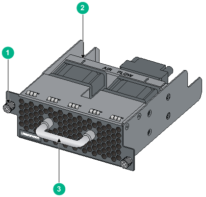
The LSWM1FANSC fan tray blows cool air from the power module side to the network port side. It comprises two separate fans. The LSWM1FANSC features small size, fast heat dissipation, and hot swapping. It can automatically adjust the fan speed, providing powerful heat dissipation for the device.
Figure 1 LSWM1FANSC fan tray
|
(1) Captive screw |
(2) Airflow direction label |
|
(3) Fan tray handle |
|
Specifications
Table 1 LSWM1FANSC specifications
|
Item |
Specifications |
|
Fans |
Two 40 × 40 × 28 mm (1.57 × 1.57 × 1.10 in) fans |
|
Airflow direction |
Fans blow air from the power module side to the network port side |
|
Max fan speed |
18500 R.P.M |
|
Max airflow |
45 CFM |
|
Max power consumption |
19.5 W |
|
Voltage |
12 V |
|
Operating temperature |
0°C to 45°C (32°F to 113°F) |
|
Relative humidity |
5% to 95% (non condensing) |
|
Storage temperature |
–40°C to 75°C (–40°F to 167°F) |
|
Relative humidity |
5% to 95% (non condensing) |
LSWM1FANSCB fan tray
Overview
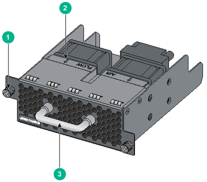
The LSWM1FANSCB fan tray draws in hot air from the network port side to the power module side. It comprises two separate fans. The LSWM1FANSCB features small size, fast heat dissipation, and hot swapping. It can automatically adjust the fan speed, providing powerful heat dissipation for the device.
Figure 2 LSWM1FANSCB fan tray
|
(1) Captive screw |
(2) Airflow direction label |
|
(3) Fan tray handle |
|
Specifications
Table 2 LSWM1FANSCB specifications
|
Item |
Specifications |
|
Fans |
Two 40 × 40 × 28 mm (1.57 × 1.57 × 1.10 in) fans |
|
Airflow direction |
Fans draw in air from the network port side to the power module side |
|
Max fan speed |
18500 R.P.M |
|
Max airflow |
45 CFM |
|
Max power consumption |
19.5 W |
|
Voltage |
12 V |
|
Operating temperature |
0°C to 45°C (32°F to 113°F) |
|
Relative humidity |
5% to 95% (non condensing) |
|
Storage temperature |
–40°C to 75°C (–40°F to 167°F) |
|
Relative humidity |
5% to 95% (non condensing) |
Installing and removing a fan tray
The installation and removal procedures for the LSWM1FANSC and LSWM1FANSCB are similar. For more information, see “Installing a fan tray” and “Removing a fan tray.”
Safety guidelines
To avoid fan tray and device damage, and bodily injury, note the following guidelines when installing or removing a fan tray:
· Wear an ESD-preventive wrist strap, and make sure the wrist strap makes good skin contact.
· Do not touch any wire or connector on a fan tray.
· Do not place a fan tray on a moist area, and avoid liquid flowing into the fan tray.
· Do not remove any component on a fan tray. If a failure occurs on the internal wires or units, contact the technical stuff to troubleshoot the problem.
Tools required
Prepare the following tools when installing and removing a fan tray:
· Phillips screwdriver
Installing a fan tray
|
|
TIP: Before installing a fan tray, make sure the air flow of the fan tray is as required. |
1. Wear an ESD-preventive wrist strap and make sure it makes good skin contact and is well grounded.
2. Take the fan tray from the package and check that the fan tray model is as required.
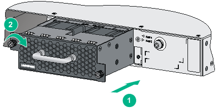
3. Face the slot into which the fan tray is to be installed. Grasp the handle of the fan tray with one hand and support the fan tray bottom with the other, and then slide the fan tray along the guide rails into the slot until the fan tray seats into the slot and has a firm contact with the connector on the backplane (see callout 1 in Figure 3).
4. Fasten the captive screws on the fan tray with a Philips screwdriver until the fan tray is fixed into the chassis (see callout 2 in Figure 3).
Figure 3 Install a fan tray
|
(1) Slide the fan tray into the slot |
(2) Fasten the captive screws |
|
|
CAUTION: · To prevent damage to the fan tray or the connector on the backplane, insert the fan tray gently. If you encounter a hard resistance while inserting the fan tray, pull out the fan tray and then insert it again. · If the captive screws cannot be tightly fixed, check the installation of the fan tray. |
Removing a fan tray
|
|
CAUTION: · When replacing a fan tray with the device running, note safety with electricity. · Do not touch rotating fans when replacing a fan tray with the device running. |
1. Wear an ESD-preventive wrist strap and make sure it makes good skin contact and is well grounded.
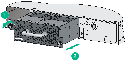
2. Face the fan tray to be removed from the device. Loosen the captive screws on the fan tray with a Philips screwdriver until the captive screws fall off the device, as shown in callout 1 in Figure 4.
3. Grasping the handle of the fan tray with one hand, pull the fan tray part way out the slot. Supporting the fan tray bottom with the other hand, pull the fan tray slowly along the guide rails out of the slot, as shown in callout 2 in Figure 4.
4. Put the removed fan tray on an anti-static mat or in its original package.
Figure 4 Remove a fan tray
|
(1) Loosen the captive screws on the fan tray |
(2) Pull the fan tray out of the slot |
|
|
CAUTION: · When removing a fan tray, take out the fan tray after the fans stop rotating. · Do not touch the fans even if the fans stop rotating to avoid affecting the fan balance, which can cause greater fan operation noise. · To ensure normal operation of the device, install a new fan tray within two minutes after the fan tray is removed if you replace a fan tray with the device running. |
