- Table of Contents
-
- 11-High Availability Configuration Guide
- 00-Preface
- 01-High Availability Overview
- 02-Ethernet OAM configuration
- 03-CFD configuration
- 04-DLDP configuration
- 05-RPR configuration
- 06-RRPP configuration
- 07-Smart Link configuration
- 08-Monitor Link configuration
- 09-VRRP configuration
- 10-BFD configuration
- 11-Track configuration
- 12-Process placement configuration
- Related Documents
-
| Title | Size | Download |
|---|---|---|
| 05-RPR configuration | 311.94 KB |
Configuration restrictions and guidelines
Configuring basic RPR functions
Configuring an RPR physical port
Configuring an RPR logical interface
Changing the RPR physical port type
Configuring the RPR station name
Configuring RPR protection reversion mode
Configuring manual protection requests
Configuring the ringlet selection table
Configuring a static ringlet selection entry
Specifying the default ringlet
Configuring the RPR fairness algorithm
Configuring reserved bandwidth or rate limiting
Configuring the hold off timer
Configuring the keepalive timer
Configuring the topology stability timer
Setting the extended packet encapsulation mode
Specifying the standard algorithm for calculating the weight in ATD frames
Testing connectivity between RPR stations
Displaying and maintaining RPR
RPR static ringlet selection entry configuration example
Configuring RPR
Overview
Resilient Packet Ring (RPR) is designed for packet based data transmission over optical fiber ring networks. RPR increases the efficiency of IP services by providing the following benefits:
· IP intelligence.
· Cost-effectiveness found in Ethernet.
· Resilience, high bandwidth, and high availability found in SONET/SDH networks.
RPR ring structure
RPR consists of dual unidirectional counter-rotating ringlets identified as Ringlet 0 and Ringlet 1, as shown in Figure 1. Ringlet 0 is the outer ring that carries clockwise data traffic. Ringlet 1 is the inner ring that carries counterclockwise data traffic.
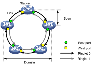
On Ringlet 0, stations send data frames out of east ports and receive data frames from west ports. On Ringlet 1, stations send data frames out of west ports and receive data frames from east ports.
Any two adjacent stations are connected by a pair of unidirectional links transmitting data in opposite directions. These two links form a span. Multiple continuous spans and their stations form a domain. A span on which data frames are not allowed to pass is called an edge. If a ring contains at least one detected edge, it is called an open ring. If the ring does not contain any detected edges, it is called a closed ring.
For the LSUM1SPMAEC0 base card, the west port is located on the subcard in slot 1, and the east port is located on the subcard in slot 2. The east and west ports on the local device must be connected to the west and east ports on the peer device, respectively.
Topology discovery
RPR performs automatic topology discovery to collect information such as the number of stations, ring state, and order of the stations on the ring. RPR uses the collected information to create a topology database. This database does not change after the ring topology becomes stable.
Topology database
Each RPR station maintains a topology database that describes the topology of the entire RPR ring. Based on this database, the station creates its ringlet selection table.
A topology database contains the following information:
· Ring topology information, such as the number of stations, ring state, and available bandwidth.
· Local station topology information, such as the MAC address, protection mode, protection state, station name, and topology checksum (TC) of the local station and the neighbor stations.
· Topology information for other stations, such as the MAC address, validity state, reachability, protection mode, station ID, station name, and reserved bandwidth.
Topology discovery process
During the topology discovery process, RPR uses the topology protection (TP), attribute discovery (ATD), and TC control frames to transmit topology data. Table 1 shows the frame content, purpose, triggering condition, and interval for the three types of control frames.
|
Items |
TP |
TC |
ATD |
|
Frame content |
Station configuration and status information. |
Station topology checksum information. |
Station attribute information, such as the MAC address and name of a station. |
|
Purpose |
Stations synchronize topology information with one another by broadcasting TP frames on the RPR ring. |
Neighbor stations compare topology information based on TC frames to determine the stability of the RPR ring. |
Stations update attribute information in the topology databases. |
|
Triggering condition |
When a station starts initializing or detects a topology change, it sends TP frames. |
After the RPR ring topology converges, the station starts to send TC frames. |
When attribute information changes, the station sends ATD frames. |
|
Interval |
User configurable intervals: · Fast interval for the first eight TP frames. · Slow interval for subsequent TP frames. |
User configurable intervals: · Fast interval for the first four TC frames. · Slow interval for subsequent TC frames. |
User configurable interval. |
RPR ringlet selection table
Each RPR station maintains ringlet selection tables for determining ringlets to send frames. A ringlet selection table entry contains such information as the destination MAC address and the ringlet for sending frames.
RPR supports the following ringlet selection tables:
· Static ringlet selection table—Contains manually configured entries to specify a ringlet for sending frames to the specified station.
· Dynamic ringlet selection table—Contains entries dynamically created based on the topology database.
· Default ringlet selection table—Specifies the default ringlet for sending frames.
· Overall ringlet selection table—Contains entries selected from the static, dynamic, and default ringlet tables. A station uses the overall ringlet selection table to forward frames.
¡ For closed ringlets, the overall ringlet selection table chooses entries based on the following principles:
- If static, dynamic, and default ringlet selection entries are available for reaching a destination station, the static entry is added to the overall ringlet selection table.
- If no static entries are available, the dynamic ringlet selection entries apply. If two shortest paths are available for reaching a destination station, the default ringlet applies.
¡ For open ringlets, the overall ringlet selection table can be created only from the dynamic ringlet selection table.
Data operations on RPR
RPR stations implement unicast, broadcast, multicast, and unknown unicast transmission by performing the following types of operations:
· Insert—Place a frame on a ringlet.
· Transit—Pass a frame to the next station.
· Copy—Deliver an inbound frame from the ring to the upper layer. Copying a frame does not remove the frame from the ring.
· Strip—Remove a frame from a ringlet. The frame is not passed to the next station.
Unicast transmission
Figure 2 Unicast transmission on an RPR ring
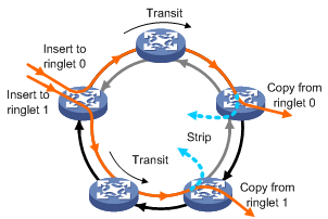
As shown in Figure 2, a unicast data frame is transmitted on an RPR ringlet using the following process:
1. The source station inserts the unicast frame into the data stream on Ringlet 0 or Ringlet 1.
2. Transit stations transit the frame.
3. The frame is copied and stripped when it reaches the destination station or when its time to live (TTL) expires.
RPR removes unicast frames from the ring at the destination station. This increases bandwidth utilization and spatial bandwidth reuse efficiency.
Broadcast, multicast, and unknown unicast transmission
Figure 3 Broadcast, multicast, and unknown unicast transmission on an RPR ring

As shown in Figure 3, a broadcast, multicast, or unknown unicast frame is transmitted on an RPR ringlet using the following process:
1. The source station inserts the frame into the data stream on Ringlet 0 or Ringlet 1.
2. Transit and destination stations copy and transit the frame if the TTL of the frame has not expired.
3. The frame is stripped when it returns to the source station or when its TTL expires.
Fault response methods
If a station is unable to forward traffic, it enters one of the following protection modes:
· Wrapping—Ringlet 0 and Ringlet 1 form a closed single ring at the point of the failure. The wrapping mode provides quick switchover to minimize frame loss, but it wastes bandwidth. The switch does not support the wrapping mode.
· Steering—The two stations at the two sides of a point of failure update their topology databases, and then broadcast TP frames at fast intervals. The source station sends frames after the new topology database is stabilized. The steering mode reduces bandwidth waste, but requires topology reconvergence that might cause frame loss and service interruption.
Figure 4 Wrapping and steering modes
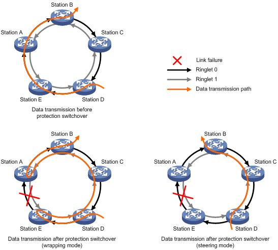
As shown in Figure 4, traffic travels from station D to station B along Ringlet 0. The transmission path is station D—station E—station A—station B. After the span between station A and station E fails, a protection switchover occurs.
· In wrapping mode, traffic that should have traveled from station E to A along Ringlet 0 is directed to Ringlet 1 to reach station A. The new transmission path is station D—station E—station D—station C—station B—station A—station B.
· In steering mode, traffic that should have traveled from station D to station B along Ringlet 0 is steered to Ringlet 1 for transmission. The new transmission path is Station D—Station C—Station B.
Protection switching occurs only when requested by a station on the ring. The following are protection requests listed in descending priority order:
· Forced switch (FS)
· Signal fail (SF), related to current physical status.
· Signal degrade (SD), related to current physical status.
· Manual switch (MS)
· Wait to restore (WTR)
· Idle
FS and MS requests are sent manually. SF, SD, and WTR requests are sent automatically. If multiple protection requests appear, the request with higher priority is processed first, for example:
· The MS request sent by a station will not be processed if a higher priority protection request is present on the RPR ring.
· If an FS request is present on the current ring, the SF or SD request automatically sent as the result of a link failure will be processed only after the FS request is cleared.
RPR interface
RPR logical interfaces allow only the packets containing VLAN tags to pass through. The VLAN cannot be the same as the VLAN to which the Layer 2 Ethernet interfaces belong. Only Layer 3 forwarding is implemented between an RPR logical interface and a Layer 2 Ethernet interface.
RPR logical interface and RPR physical port overview
An RPR logical interface is automatically bound with two RPR physical ports. The configuration on the RPR logical interface can be synchronized to the RPR physical ports.
Available RPR physical port types include RPRXGE and RPRPOS. Each RPR physical port corresponds to a mate port. Mate ports transmit data packets and protocol packets for RPR physical ports on the ring.
RPR master/subordinate port
All calculation concerning the operation of RPR is done on the master port, and the calculation result is synchronized to the subordinate port for consistency. Examples of RPR-related calculation include execution of configuration commands, protection event processing, and RPR frame sending for topology discovery.
For a card, the physical port with a smaller port ID is the RPR master port, the physical port with a greater ID is the RPR subordinate port.
Centralized RPR
An RPR station is identical to an RPR logical interface bound with two RPR physical ports. The two RPR physical ports transmit or receive data on the ring. The RPR logical interface is used for configuration.
In centralized RPR, the two RPR physical ports are located on the two subcards in a base card. When the subcard where the two RPR physical ports are located goes down, the RPR station fails.
Protocols and standards
IEEE802.17, Resilient packet ring (RPR) access method and physical layer specifications
Configuration restrictions and guidelines
· Only the LSUM1SPMAEC0 base card supports RPR. To use the base card, you must install the LSR1DRUP1L1 subcard. The LSR1DRUP1L1 subcard does not support hot swapping.
· RPR logical interfaces do not support MPLS and VRRP.
RPR configuration task list
|
Task at a glance |
|
Configuring basic RPR functions: · (Optional.) Configuring an RPR physical port · (Optional.) Configuring an RPR logical interface · (Optional.) Changing the RPR physical port type · (Optional.) Configuring the RPR station name |
|
(Optional.) Configuring RPR protection: |
|
(Optional.) Configuring the ringlet selection table: |
|
(Optional.) Configuring the RPR fairness algorithm: |
|
(Optional.) Configuring RPR timers: · Configuring the hold off timer · Configuring the keepalive timer |
|
(Optional.) Setting the extended packet encapsulation mode |
|
(Optional.) Specifying the standard algorithm for calculating the weight in ATD frames |
|
(Optional.) Testing connectivity between RPR stations |
Configuring basic RPR functions
Configuring an RPR physical port
RPR physical ports include RPRXGE interfaces and RPRPOS interfaces. By default, an RPR physical port is a 10GPOS port.
To configure an RPRXGE interface:
|
Step |
Command |
Remarks |
|
1. Enter system view. |
system-view |
N/A |
|
2. Enter RPRXGE interface view. |
interface rprxge interface-number |
N/A |
|
3. (Optional.) Configure the description for the interface. |
description text |
By default, the description of an interface is interface-name Interface. |
|
4. (Optional.) Set the expected bandwidth for the interface. |
bandwidth bandwidth-value |
By default, the expected bandwidth (in kbps) is the interface baud rate divided by 1000. |
|
5. (Optional.) Set the packet statistics collection interval for the interface. |
flow-interval interval |
By default, the packet statistics collection interval is 300 seconds. |
|
6. Bring up the interface. |
undo shutdown |
By default, the interface is enabled. |
|
7. (Optional.) Restore the default settings for the interface. |
default |
N/A |
To configure an RPRPOS interface:
|
Step |
Command |
Remarks |
|
1. Enter system view. |
system-view |
N/A |
|
2. Enter RPRPOS interface view. |
interface rprpos interface-number |
N/A |
|
3. (Optional.) Configure the description for the interface. |
description text |
By default, the description of an interface is interface-name Interface. |
|
4. (Optional.) Set the keepalive interval for the interface. |
timer-hold seconds |
By default, the keepalive interval is 10 seconds. |
|
5. (Optional.) Configure the overhead bytes for the interface. |
· Configure the C2 path signal label byte: · Configure the J0 regenerator section trace
byte: · Configure the J1 path trace byte: |
By default: · The C2 byte is 0x16. · The system uses the SDH framing format. · In SDH frames, both J0 and J1 bytes are empty strings. |
|
6. (Optional.) Set the framing format for the interface. |
frame-format { sdh | sonet } |
By default, the framing format is SDH. |
|
7. (Optional.) Set the SD or SF alarm threshold for the interface. |
threshold { sd sdvalue | sf sfvalue } * |
By default, the SD alarm threshold is 10e–5 and the SF alarm threshold is 10e–3. |
|
8. (Optional.) Set the packet statistics collection interval for the interface. |
flow-interval interval |
By default, the packet statistics collection interval is 300 seconds. |
|
9. (Optional.) Set the expected bandwidth for the interface. |
bandwidth bandwidth-value |
By default, the expected bandwidth (in kbps) is the interface baud rate divided by 1000. |
|
10. Bring up the interface. |
undo shutdown |
By default, the interface is enabled. |
|
11. (Optional.) Restore the default settings of the interface. |
default |
N/A |
Configuring an RPR logical interface
|
Step |
Command |
Remarks |
|
1. Enter system view. |
system-view |
N/A |
|
2. Enter RPR logical interface view. |
interface rpr interface-number |
N/A |
|
3. (Optional.) Configure the description for the interface. |
description text |
By default, the description of an interface is interface-name Interface. |
|
4. (Optional.) Set the expected bandwidth for the interface. |
bandwidth bandwidth-value |
By default, the expected bandwidth (in kbps) is the interface baud rate divided by 1000. |
|
5. (Optional.) Restore the default settings for the interface. |
default |
N/A |
Changing the RPR physical port type
After you change the RPR physical port type, the following results will occur:
· The subcard where the RPR physical ports reside will reboot, and the configuration on the ports will be lost.
· The ports previously assigned to the non-default Multitenant Device Context (MDC) will be assigned to the default MDC. You must manually change the MDC assignment.
· The port will be automatically bound to the RPR logical interface.
To change the RPR physical port type on an RPR logical interface:
|
Step |
Command |
Remarks |
|
1. Enter system view. |
system-view |
N/A |
|
2. Enter RPR physical port view. |
interface { rprpos | rprxge |} interface-number |
N/A |
|
3. Change the RPR physical port type. |
rpr port-type { 10ge | 10gpos } |
By default, the RPR physical port type is 10GPOS. This command applies only to 10G POS and 10-GE RPR physical ports. |
Configuring the RPR station name
|
Step |
Command |
Remarks |
|
1. Enter system view. |
system-view |
N/A |
|
2. Enter RPR logical interface view. |
interface rpr interface-number |
N/A |
|
3. Configure a station name. |
rpr station-name station-name |
By default, no station name is configured. |
Configuring RPR protection
Configuring RPR protection reversion mode
The following protection reversion modes are available:
· Revertive mode—A station resumes the idle state when the WTR timer expires.
· Non-revertive mode—The station remains in automatic protection state when the WTR timer expires and does not resume the idle state until a higher protection request is present on the ring.
To configure the RPR protection reversion mode for the RPR station:
|
Step |
Command |
Remarks |
|
1. Enter system view. |
system-view |
N/A |
|
2. Enter RPR logical interface view. |
interface rpr interface-number |
N/A |
|
3. Configure the non-revertive mode. |
rpr reversion-mode non-revertive |
By default, a station uses the revertive mode. |
Configuring manual protection requests
You can send FS or MS protection requests to trigger protection switchover or send idle protection requests to clear protection requests that are manually sent.
To configure a manual protection request:
|
Step |
Command |
Remarks |
|
1. Enter system view. |
system-view |
N/A |
|
2. Enter RPR logical interface view. |
interface rpr interface-number |
N/A |
|
3. Configure a manual protection request on a ringlet. |
rpr admin-request { fs | idle | ms } { ringlet0 | ringlet1 } |
By default, a ring is not configured with any protection request. If you execute this command repeatedly for an RPR physical port, the most recent configuration takes effect. |
Configuring the ringlet selection table
Configuring a static ringlet selection entry
Static ringlet selection entries take effect only when the RPR ring is closed.
To configure a static ringlet selection entry:
|
Step |
Command |
Remarks |
|
1. Enter system view. |
system-view |
N/A |
|
2. Enter RPR logical interface view. |
interface rpr interface-number |
N/A |
|
3. Configure a static ringlet selection entry. |
rpr static-rs mac-address { ringlet0 | ringlet1 } |
By default, no static ringlet selection entry is configured. |
Specifying the default ringlet
When the default ringlet is unable to forward data because of a faulty span, the other ringlet takes over.
To specify the default ringlet:
|
Step |
Command |
Remarks |
|
1. Enter system view. |
system-view |
N/A |
|
2. Enter RPR logical interface view. |
interface rpr interface-number |
N/A |
|
3. Specify Ringlet 1 as the default ringlet. |
rpr default-rs ringlet1 |
By default, the default ringlet is Ringlet 0. |
Configuring the RPR fairness algorithm
RPR fairness algorithm ensures the transmission quality over RPR rings.
Configuring reserved bandwidth or rate limiting
|
|
IMPORTANT: The total bandwidth reserved for subclass A0 by the stations on a ringlet must be less than the ringlet bandwidth. |
RPR traffic is divided into class A, class B, and class C, with decreasing priorities.
· Class A includes the following subclasses:
¡ A0—RPR reserves bandwidth for traffic of subclass A0. When congestion occurs, the unused reserved bandwidth cannot be used by lower-priority traffic.
¡ A1—RPR limits rate for traffic of subclass A1. When congestion occurs, subclass A1 allows lower-priority traffic to use the unused bandwidth.
· Class B includes the following subclasses:
¡ B-CIR—Contains traffic with data rate smaller than the predefined rate limit.
¡ B-EIR—Contains traffic with data rate greater than the predefined rate limit.
· Class C traffic has the lowest priority.
To configure reserved bandwidth or rate limit for a traffic class:
|
Step |
Command |
Remarks |
|
1. Enter system view. |
system-view |
N/A |
|
2. Enter RPR logical interface view. |
interface rpr interface-number |
N/A |
|
3. Configure reserved bandwidth or rate limit for a class on a ringlet. |
rpr rate-limit { high | low | medium | reserved } { ringlet0 | ringlet1 } value |
By default, no bandwidth is reserved for subclass A0. The rate limit is 2‰ for subclass A1, 0‰ for class B-CIR, and 1000‰ for B-EIR and class C. |
Configuring station weight
RPR fairness algorithm regulates traffic on the RPR ring. You can assign a weight to a station to adjust the ratio of its available service bandwidth to the total non-reserved bandwidth of the RPR ring.
To configure the fairness weight of an RPR station:
|
Step |
Command |
Remarks |
|
1. Enter system view. |
system-view |
N/A |
|
2. Enter RPR logical interface view. |
interface rpr interface-number |
N/A |
|
3. Configure the weight of the station. |
rpr weight { ringlet0 | ringlet1 } value |
By default, the weigh for a station is 1. |
Configuring RPR timers
Configuring the ATD timer
The ATD timer defines the interval for sending ATD frames.
To configure the ATD timer:
|
Step |
Command |
Remarks |
|
1. Enter system view. |
system-view |
N/A |
|
2. Enter RPR logical interface view. |
interface rpr interface-number |
N/A |
|
3. Set the ATD timer. |
rpr timer atd atd-value |
By default, the ATD timer is 1 second. |
Configuring the hold off timer
The hold off timer defines the delay for the physical layer to send a protection request after detecting a link failure.
To configure the hold off timer:
|
Step |
Command |
Remarks |
|
1. Enter system view. |
system-view |
N/A |
|
2. Enter RPR logical interface view. |
interface rpr interface-number |
N/A |
|
3. Set the hold off timer. |
rpr timer holdoff holdoff-value |
By default, the hold off timer is 0 milliseconds. |
Configuring the keepalive timer
A station sends single choke fairness frames (SCFFs) periodically to notify the neighbor stations of its normal operation state. When a station fails to receive an SCFF, it starts a keepalive timer. If it does not receive an SCFF frame after the timer expires, the station sends an SF protection request.
To configure the keepalive timer:
|
Step |
Command |
Remarks |
|
1. Enter system view. |
system-view |
N/A |
|
2. Enter RPR logical interface view. |
interface rpr interface-number |
N/A |
|
3. Set the keepalive timer. |
rpr timer keepalive keepalive-value |
By default, the keepalive timer is 3 milliseconds. |
Configuring the topology stability timer
When a station detects a ring topology change, it starts the topology stability timer and collects topology information to update its topology database. After the timer expires, the station checks the validity of received topology information. If the information is valid, the station enters topology valid state. If the information is invalid, the station restarts the timer.
To configure the topology stability timer:
|
Step |
Command |
Remarks |
|
1. Enter system view. |
system-view |
N/A |
|
2. Enter RPR logical interface view. |
interface rpr interface-number |
N/A |
|
3. Set the topology stability timer. |
rpr timer stability stability-value |
By default, the topology stability timer is 40 milliseconds. |
Configuring the TC timers
The TC fast and slow timers define the fast and slow intervals for sending TC frames, respectively. When the ring topology checksum changes, the station sends four TC frames at the fast interval. When the ring topology is stable, the station sends TC frames at the slow interval.
To configure the TC timers:
|
Step |
Command |
Remarks |
|
1. Enter system view. |
system-view |
N/A |
|
2. Enter RPR logical interface view. |
interface rpr interface-number |
N/A |
|
3. Set the TC fast timer. |
rpr timer tc-fast tc-fast-value |
By default, the TC fast timer is 10 milliseconds. |
|
4. Set the TC slow timer. |
rpr timer tc-slow tc-slow-value |
By default, the TC slow timer is 100 milliseconds. |
Configuring the TP timers
The TP fast and slow timers define the fast and slow intervals for sending TP frames, respectively. When a station starts initializing or detects a topology change, it sends eight TP frames at the fast interval. When the ring topology is stable, the station sends TP frames at the slow interval.
To configure the TP timers:
|
Step |
Command |
Remarks |
|
1. Enter system view. |
system-view |
N/A |
|
2. Enter RPR logical interface view. |
interface rpr interface-number |
N/A |
|
3. Set the TP fast timer. |
rpr timer tp-fast tp-fast-value |
By default, the TP fast timer is 10 milliseconds. |
|
4. Set the TP slow timer. |
rpr timer tp-slow tp-slow-value |
By default, the TP slow timer is 100 milliseconds. |
Configuring the WTR timer
When a protection switching event occurs on a station due to link failure, the station enters automatic protection state. After the link recovers, the station enters the idle protection state. The WTR timer defines the transition interval from the automatic protection state to the idle state.
To configure the WTR timer:
|
Step |
Command |
Remarks |
|
1. Enter system view. |
system-view |
N/A |
|
2. Enter RPR logical interface view. |
interface rpr interface-number |
N/A |
|
3. Set the WTR timer. |
rpr timer wtr wtr-value |
By default, the WTR timer is 10 milliseconds. |
Setting the extended packet encapsulation mode
|
|
IMPORTANT: · If a ring contains S9500E devices, you must set the extended packet encapsulation mode. As a best practice, set the standard packet encapsulation mode if the ring does not contain S9500E devices. · All devices on a ring must be configured with the same packet encapsulation mode. |
An RPR station uses one of the following packet encapsulation modes:
· Standard mode—The RPR station forwards RPR packets to the destination station without modifying the packet content.
· Extended mode—The RPR station removes the CRC field from RPR packets before sending them. The destination station calculates a new CRC based on the packet payload, and encapsulates the CRC into the packets.
To set the extended packet encapsulation mode:
|
Step |
Command |
Remarks |
|
1. Enter system view. |
system-view |
N/A |
|
2. Enter RPR logical interface view. |
interface rpr interface-number |
N/A |
|
3. Set the extended packet encapsulation mode. |
rpr encapsulation extend |
By default, an RPR station uses the standard packet encapsulation mode. |
Specifying the standard algorithm for calculating the weight in ATD frames
|
|
IMPORTANT: · If a ring contains S9500E and S9500 devices, use the default algorithm for calculating the weight in ATD frames. · All devices on a ring must be configured with the same algorithm for calculating the weight in ATD frames. |
An RPR station can use the proprietary or standard algorithm for calculating the weight in ATD frames.
To specify the standard algorithm for calculating the weight in ATD frames:
|
Step |
Command |
Remarks |
|
1. Enter system view. |
system-view |
N/A |
|
2. Enter RPR logical interface view. |
interface rpr interface-number |
N/A |
|
3. Specify the standard algorithm for calculating the weight in ATD frames. |
rpr weight standard |
By default, an RPR station uses the proprietary algorithm for calculating the weight in ATD frames. |
Testing connectivity between RPR stations
You can use Echo Request/Echo Response messages to test the connectivity between two stations and locate failure points. The connectivity between two stations is normal if the following conditions exist:
· The destination station can receive the Echo Request messages on the specified ringlet.
· The source station can receive the Echo Response messages on the specified ringlet.
To test the connectivity to an RPR station:
|
Step |
Command |
Remarks |
|
4. Enter system view. |
system-view |
N/A |
|
5. Enter RPR logical interface view. |
interface rpr interface-number |
N/A |
|
6. Test the connectivity between the current station and a specific station. |
rpr echo mac mac-address [ -c c-value | -r { reverse | ringlet0 | ringlet1 } | -s { ringlet0 | ringlet1 } | -t t-value ] * |
If no sending and receiving ringlets are specified, the stations selects ringlets from the overall ringlet selection table for transmitting Echo Request packets and Echo Response. |
Displaying and maintaining RPR
Execute display commands in any view and reset commands in user view.
|
Task |
Command |
|
Display RPR interface information. |
|
|
Display RPR logical interface-to-physical port bindings. |
display rpr bind-info [ { rpr| rprpos | rprxge } interface-number ] |
|
Display RPR defect information. |
display rpr defect [ rpr interface-number ] |
|
Display RPR fairness settings. |
display rpr fairness [ rpr interface-number ] |
|
Display RPR protection information. |
display rpr protection [ rpr interface-number ] |
|
Display RPR ringlet selection table information. |
display rpr rs-table { default | dynamic | overall | static } [ rpr interface-number ] |
|
Display traffic statistics on the RPR ring. |
display rpr statistics { dmac | smac } [ mac-address ] [ rpr interface-number ] |
|
Display the settings of all configurable RPR timers. |
display rpr timers [ rpr interface-number ] |
|
Display RPR topology information. |
display rpr topology { all | local | ring | stations } [ brief ] [ rpr interface-number ] |
|
Clear RPR interface statistics. |
reset counters interface [ { rpr | rprpos | rprxge } [ interface-number ] ] |
|
Clear protection event statistics on the RPR station. |
reset rpr protection statistics [ rpr interface-number ] |
RPR configuration examples
RPR static ringlet selection entry configuration example
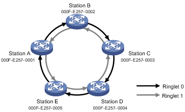
Network requirements
As shown in Figure 5, configure Ringlet 1 as the sending ringlet for frames destined from Station A to Station B when no edge occurs on the RPR ring.
Configuration procedure
# Create RPR logical interface RPR 4/0/1 on Station A.
[StationA] interface rpr 4/0/1
# Create a static ringlet selection entry on RPR 4/0/1 by specifying Ringlet 1 for sending data frames destined to 000f-e257-0002.
[StationA-RPR4/0/1] rpr static-rs 000f-e257-0002 ringlet1
[StationA-RPR4/0/1] quit
Verifying the configuration
# Display ring topology information for Station A.
[StationA] display rpr topology ring
Ring-level topology information on interface RPR4/0/1:
Number of stations on Ringlet0: 4
Number of stations on Ringlet1: 4
Total number of stations on the ring: 5
Jumbo preference: Jumbo
Ring topology type: Closed ring
# Display static ringlet selection table information for Station A.
[StationA] display rpr rs-table static
Static ringlet selection table on interface RPR4/0/1:
MAC address Ringlet ID Status
-----------------------------------
000f-e257-0002 1 Valid
--- Entries in total: 1 ---
# Display overall ringlet selection table information for Station A.
[StationA] display rpr rs-table overall
Overall ringlet selection table on interface RPR4/0/1:
MAC address Ringlet ID TTL Type IP address Station name
-------------------------------------------------------------------------------
000f-e257-0002 1 4 Static -
000f-e257-0003 0 2 Dynamic -
000f-e257-0004 1 2 Dynamic -
000f-e257-0005 1 1 Dynamic -
--- Entries in total: 4 ---
Troubleshooting RPR
RPR physical port failure
Symptom
An RPR physical port is down, or goes down and comes up frequently.
Solution
· Make sure two optical fibers are connected correctly for the RPR physical port.
¡ One optical fiber connects the Rx end of the port to the Tx end of the peer port.
¡ Another optical fiber connects the Tx end of the port to the Rx end of the peer port.
· Make sure the types of the RPR physical ports on the local device and the peer device are the same. If the port types are different, use the rpr port-type command to change the port type.