- Table of Contents
-
- 07-IP Multicast Configuration Guide
- 00-Preface
- 01-Multicast Overview
- 02-IGMP snooping configuration
- 03-PIM snooping configuration
- 04-Multicast VLAN configuration
- 05-Multicast routing and forwarding configuration
- 06-IGMP configuration
- 07-PIM configuration
- 08-MSDP configuration
- 09-Multicast VPN configuration
- 10-MLD snooping configuration
- 11-IPv6 PIM snooping configuration
- 12-IPv6 multicast VLAN configuration
- 13-IPv6 multicast routing and forwarding configuration
- 14-MLD configuration
- 15-IPv6 PIM configuration
- Related Documents
-
| Title | Size | Download |
|---|---|---|
| 13-IPv6 multicast routing and forwarding configuration | 168.94 KB |
Contents
Configuring IPv6 multicast routing and forwarding
IPv6 multicast forwarding across IPv6 unicast subnets
Enabling IPv6 multicast routing
Configuring IPv6 multicast routing and forwarding
Specifying the longest prefix match principle
Configuring IPv6 multicast load splitting
Configuring an IPv6 multicast forwarding boundary
Configuring IPv6 static multicast MAC address entries
Enabling IPv6 multicast forwarding between sub-VLANs of a super VLAN
Displaying and maintaining IPv6 multicast routing and forwarding
IPv6 multicast forwarding over a GRE tunnel configuration example
Configuring IPv6 multicast routing and forwarding
Overview
IPv6 multicast routing and forwarding uses the following tables:
· IPv6 multicast protocols' routing tables, such as the IPv6 PIM routing table.
· General IPv6 multicast routing table that summarizes the multicast routing information generated by different IPv6 multicast routing protocols. The IPv6 multicast routing information from IPv6 multicast sources to IPv6 multicast groups are stored in a set of (S, G) routing entries.
· IPv6 multicast forwarding table that guides IPv6 multicast forwarding. The optimal routing entries in the IPv6 multicast routing table are added to the IPv6 multicast forwarding table.
RPF check mechanism
An IPv6 multicast routing protocol relies on the existing IPv6 unicast routing information or IPv6 MBGP routes to create IPv6 multicast routing entries. When creating IPv6 multicast routing table entries, the IPv6 multicast routing protocol uses the reverse path forwarding (RPF) check mechanism to ensure IPv6 multicast data delivery along the correct path. The RPF check also helps avoid data loops.
A multicast routing protocol uses the following tables to perform the RPF check:
· IPv6 unicast routing table—Contains unicast routing information.
· IPv6 MBGP routing table—Contains IPv6 MBGP multicast routing information.
RPF check process
The router performs the RPF check on an IPv6 multicast packet as follows:
1. The router chooses an optimal route back to the packet source separately from the IPv6 unicast and IPv6 MBGP routing tables.
In RPF check, the "packet source" means difference things in difference situations:
¡ For a packet that travels along the SPT, the packet source is the IPv6 multicast source.
¡ For a packet that travels along the RPT, the packet source is the RP.
¡ For a bootstrap message originated from the BSR, the packet source is the BSR.
For more information about the concepts of SPT, RPT, source-side RPT, RP, and BSR, see "Configuring IPv6 PIM."
2. The router selects one of the optimal routes as the RPF route as follows:
¡ If the router uses the longest prefix match principle, the route with a higher prefix length becomes the RPF route. If the routes have the same prefix length, the route with a higher route preference becomes the RPF route. If the routes have the same route preference, the IPv6 MBGP route becomes the RPF route.
For more information about the route preference, see Layer 3—IP Routing Configuration Guide.
¡ If the router does not use the longest prefix match principle, the route with a higher route preference becomes the RPF route. If the routes have the same route preference, the IPv6 MBGP route becomes the RPF route.
In the RPF route, the outgoing interface is the RPF interface and the next hop is the RPF neighbor.
3. The router checks whether the packet arrived at the RPF interface. If yes, the RPF check succeeds and the packet is forwarded. If not, the RPF check fails and the packet is discarded.
RPF check implementation in IPv6 multicast
Implementing an RPF check on each received IPv6 multicast packet would heavily burden the router. The use of an IPv6 multicast forwarding table is the solution to this issue. When the router creates an IPv6 multicast forwarding entry for an IPv6 (S, G) packet, it sets the RPF interface of the packet as the incoming interface of the (S, G) entry. After the router receives another (S, G) packet, it looks up its IPv6 multicast forwarding table for a matching (S, G) entry:
· If no match is found, the router first determines the RPF route back to the packet source. Then, it creates a forwarding entry with the RPF interface as the incoming interface and performs one of the following tasks:
¡ If the receiving interface is the RPF interface, the RPF check succeeds and the router forwards the packet out of all outgoing interfaces.
¡ If the receiving interface is not the RPF interface, the RPF check fails and the router discards the packet.
· If a match is found and the matching forwarding entry contains the receiving interface, the router forwards the packet out of all outgoing interfaces.
· If a match is found but the matching forwarding entry does not contain the receiving interface, the router determines the RPF route back to the packet source. Then, the router performs one of the following tasks:
¡ If the RPF interface is the incoming interface, it means that the forwarding entry is correct but the packet traveled along a wrong path. The packet fails the RPF check, and the router discards the packet.
¡ If the RPF interface is not the incoming interface, it means that the forwarding entry has expired. The router replaces the incoming interface with the RPF interface and matches the receiving interface against the RPF interface. If the receiving interface is the RPF interface, the router forwards the packet out of all outgoing interfaces. Otherwise, it discards the packet.
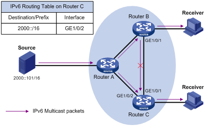
As shown in Figure 1, assume that IPv6 unicast routes are available on the network. IPv6 MBGP is not configured. IPv6 multicast packets travel along the SPT from the multicast source to the receivers. The IPv6 multicast forwarding table on Router C contains the (S, G) entry, with GigabitEthernet 1/0/2 as the RPF interface.
· If an IPv6 multicast packet arrives at Router C on GigabitEthernet 1/0/2, the receiving interface is the incoming interface of the (S, G) entry. Router C forwards the packet out of all outgoing interfaces.
· If an IPv6 multicast packet arrives at Router C on GigabitEthernet 1/0/1, the receiving interface is not the incoming interface of the (S, G) entry. Router C searches its IPv6 unicast routing table and finds that the outgoing interface to the source (the RPF interface) is GigabitEthernet 1/0/2. This means that the (S, G) entry is correct but the packet traveled along a wrong path. The packet fails the RPF check, and Router C discards the packet.
IPv6 multicast forwarding across IPv6 unicast subnets
A network might have routers that do not support IPv6 multicast protocols. When IPv6 multicast data is forwarded to a router of which the next hop supports only IPv6 unicast protocols, the forwarding path is blocked. To implement IPv6 multicast forwarding across unicast subnets, you can establish a tunnel between the IPv6 multicast routers at the edges of the two IPv6 unicast subnets.
Figure 2 IPv6 multicast data transmission through a tunnel
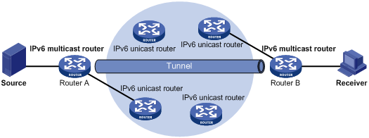
As shown in Figure 2, a tunnel is established between IPv6 multicast routers Router A and Router B. Router A encapsulates IPv6 multicast data in unicast IPv6 packets, and forwards them to Router B across the tunnel through IPv6 unicast routers. Then, Router B strips off the unicast IPv6 header and continues to forward the IPv6 multicast data to the receiver.
Configuration task list
|
Tasks at a glance |
|
(Required.) Enabling IPv6 multicast routing |
|
(Optional.) Configuring IPv6 multicast routing and forwarding: · (Optional.) Specifying the longest prefix match principle · (Optional.) Configuring IPv6 multicast load splitting · (Optional.) Configuring an IPv6 multicast forwarding boundary · (Optional.) Configuring IPv6 static multicast MAC address entries · (Optional.) Enabling IPv6 multicast forwarding between sub-VLANs of a super VLAN |
Enabling IPv6 multicast routing
Enable IPv6 multicast routing before you configure any Layer 3 IPv6 multicast functionality in the public network or VPN instance.
To enable IPv6 multicast routing:
|
Step |
Command |
Remarks |
|
1. Enter system view. |
system-view |
N/A |
|
2. Enable IPv6 multicast routing and enter IPv6 MRIB view. |
ipv6 multicast routing [ vpn-instance vpn-instance-name ] |
By default, IPv6 multicast routing is disabled. |
Configuring IPv6 multicast routing and forwarding
Before you configure IPv6 multicast routing and forwarding, complete the following tasks:
· Configure an IPv6 unicast routing protocol so that all devices in the domain can interoperate at the network layer.
· Configure IPv6 PIM-DM or IPv6 PIM-SM.
Specifying the longest prefix match principle
You can enable the device to use the longest prefix match principle for RPF route selection. For more information about RPF route selection, see "RPF check process."
To specify the longest prefix match principle:
|
Step |
Command |
Remarks |
|
1. Enter system view. |
system-view |
N/A |
|
2. Enter IPv6 MRIB view. |
ipv6 multicast routing [ vpn-instance vpn-instance-name ] |
N/A |
|
3. Specify the longest prefix match principle. |
longest-match |
By default, the route preference principle is used. |
Configuring IPv6 multicast load splitting
You can enable the device to split multiple IPv6 multicast data flows on a per-source basis or on a per-source-and-group basis.
You do not need to enable IPv6 multicast routing before this configuration.
To configure IPv6 multicast load splitting:
|
Step |
Command |
Remarks |
|
1. Enter system view. |
system-view |
N/A |
|
2. Enter IPv6 MRIB view. |
ipv6 multicast routing [ vpn-instance vpn-instance-name ] |
N/A |
|
3. Configure IPv6 multicast load splitting. |
load-splitting {source | source-group } |
By default, IPv6 multicast load splitting is disabled. This command does not take effect on IPv6 BIDIR-PIM. |
Configuring an IPv6 multicast forwarding boundary
You can configure an interface as an IPv6 multicast forwarding boundary for an IPv6 multicast group range. The interface cannot receive or forward IPv6 multicast packets for the groups in the range.
To configure an IPv6 multicast forwarding boundary:
|
Step |
Command |
Remarks |
|
1. Enter system view. |
system-view |
N/A |
|
2. Enter interface view. |
interface interface-type interface-number |
N/A |
|
3. Configure an IPv6 multicast forwarding boundary. |
ipv6 multicast boundary { ipv6-group-address prefix-length | scope { scope-id | admin-local | global | organization-local | site-local } } |
By default, the interface is not configured as an IPv6 multicast forwarding boundary. |
Configuring IPv6 static multicast MAC address entries
In Layer-2 multicast, a Layer-2 IPv6 multicast protocol (such as MLD snooping) can dynamically add IPv6 multicast MAC address entries. Or, you can manually configure IPv6 multicast MAC address entries.
|
|
TIP: The IPv6 multicast MAC address that can be configured in the MAC address entry must be unused. An IPv6 multicast MAC address is the MAC address in which the least significant bit of the most significant octet is 1. |
You can configure IPv6 static multicast MAC address entries on the specified interface in system view, or on the current interface in interface view.
Configuring a static IPv6 multicast MAC address entry in system view
|
Step |
Command |
Remarks |
|
1. Enter system view. |
system-view |
N/A |
|
2. Configure a static IPv6 multicast MAC address entry. |
mac-address multicast mac-address interface interface-list vlan vlan-id |
By default, static IPv6 multicast MAC address entries do not exist. |
Configuring a static IPv6 multicast MAC address entry in interface view
|
Step |
Command |
Remarks |
|
1. Enter system view. |
system-view |
N/A |
|
2. Enter Layer 2 Ethernet interface/Layer 2 aggregate interface view. |
interface interface-type interface-number |
N/A |
|
3. Configure a static IPv6 multicast MAC address entry. |
mac-address multicast mac-address vlan vlan-id |
By default, static IPv6 multicast MAC address entries do not exist. |
Enabling IPv6 multicast forwarding between sub-VLANs of a super VLAN
A super VLAN is associated with multiple sub-VLANs. Sub-VLANs are isolated with each other at Layer 2. For information about the super VLAN and sub-VLANs, see Layer 2—LAN Switching Configuration Guide.
To enable multicast forwarding between sub-VLANs that are associated with a super VLAN:
|
Step |
Command |
Remarks |
|
1. Enter system view. |
system-view |
N/A |
|
2. Enter VLAN interface view. |
interface vlan-interface interface-number |
N/A |
|
3. Enable IPv6 multicast forwarding between sub-VLANs that are associated with a super VLAN. |
ipv6 multicast forwarding supervlan community |
By default, IPv6 multicast data cannot be forwarded among sub-VLANs of a super VLAN. |
|
4. Clear all IPv6 multicast forwarding entries with super VLAN interface as the incoming interface. |
reset ipv6 multicast [ vpn-instance vpn-instance-name ] forwarding-table { { ipv6-source-address [ prefix-length ] | ipv6-group-address [ prefix-length ] | incoming-interface { interface-type interface-number } } * | all } |
N/A |
Displaying and maintaining IPv6 multicast routing and forwarding
|
|
CAUTION: The reset commands might cause IPv6 multicast data transmission failures. |
Execute display commands in any view and reset commands in user view.
|
Task |
Command |
|
Display IPv6 static multicast MAC address entries. |
display mac-address [ mac-address [ vlan vlan-id ] | [ multicast ] [ vlan vlan-id ] [ count ] ] |
|
Display information about the interfaces maintained by the IPv6 MRIB. |
display ipv6 mrib [ vpn-instance vpn-instance-name ] interface [ interface-type interface-number ] |
|
Display IPv6 multicast boundary information. |
display ipv6 multicast [ vpn-instance vpn-instance-name ] boundary { group [ ipv6-group-address [ prefix-length ] ] | scope [ scope-id ] } [ interface interface-type interface-number ] |
|
Display DF information (in standalone mode). |
display ipv6 multicast [ vpn-instance vpn-instance-name ] forwarding df-info [ ipv6-rp-address ] [ verbose ] [ slot slot-number ] |
|
Display DF information (in IRF mode). |
display ipv6 multicast [ vpn-instance vpn-instance-name ] forwarding df-info [ ipv6-rp-address ] [ verbose ] [ chassis chassis-number slot slot-number ] |
|
Display statistics for IPv6 multicast forwarding events (in standalone mode). |
display ipv6 multicast [ vpn-instance vpn-instance-name ] forwarding event [ slot slot-number ] |
|
Display statistics for IPv6 multicast forwarding events (in IRF mode). |
display ipv6 multicast [ vpn-instance vpn-instance-name ] forwarding event [ chassis chassis-number slot slot-number ] |
|
Display IPv6 multicast forwarding entries (in standalone mode). |
display ipv6 multicast [ vpn-instance vpn-instance-name ] forwarding-table [ ipv6-source-address [ prefix-length ] | ipv6-group-address [ prefix-length ] | incoming-interface interface-type interface-number | outgoing-interface { exclude | include | match } interface-type interface-number | slot slot-number | statistics ] * |
|
Display IPv6 multicast forwarding entries (in IRF mode). |
display ipv6 multicast [ vpn-instance vpn-instance-name ] forwarding-table [ ipv6-source-address [ prefix-length ] | ipv6-group-address [ prefix-length ] | chassis chassis-number slot slot-number | incoming-interface interface-type interface-number | outgoing-interface { exclude | include | match } interface-type interface-number | statistics ] * |
|
Display information about the DF list in the IPv6 multicast forwarding table (in standalone mode). |
display ipv6 multicast [ vpn-instance vpn-instance-name ] forwarding-table df-list [ ipv6-group-address ] [ verbose ] [ slot slot-number ] |
|
Display information about the DF list in the IPv6 multicast forwarding table (in IRF mode). |
display ipv6 multicast [ vpn-instance vpn-instance-name ] forwarding-table df-list [ ipv6-group-address ] [ verbose ] [ chassis chassis-number slot slot-number ] |
|
Display IPv6 multicast routing entries. |
display ipv6 multicast [ vpn-instance vpn-instance-name ] routing-table [ ipv6-source-address [ prefix-length ] | ipv6-group-address [ prefix-length ] | incoming-interface interface-type interface-number | outgoing-interface { exclude | include | match } interface-type interface-number ] * |
|
Display RPF information for an IPv6 multicast source. |
display ipv6 multicast [ vpn-instance vpn-instance-name ] rpf-info ipv6-source-address [ ipv6-group-address ] |
|
Clear statistics for IPv6 multicast forwarding events. |
reset ipv6 multicast [ vpn-instance vpn-instance-name ] forwarding event |
|
Clear IPv6 multicast forwarding entries. |
reset ipv6 multicast [ vpn-instance vpn-instance-name ] forwarding-table { { ipv6-source-address [ prefix-length ] | ipv6-group-address [ prefix-length ] | incoming-interface { interface-type interface-number } } * | all } |
|
Clear IPv6 multicast routing entries. |
reset ipv6 multicast [ vpn-instance vpn-instance-name ] routing-table { { ipv6-source-address [ prefix-length ] | ipv6-group-address [ prefix-length ] | incoming-interface interface-type interface-number } * | all } |
|
|
NOTE: When a routing entry is cleared, the associated forwarding entry is also cleared. When a forwarding entry is cleared, the associated routing entry is also cleared. |
IPv6 multicast forwarding over a GRE tunnel configuration example
Network requirements
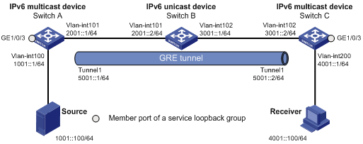
As shown in Figure 3:
· IPv6 multicast routing and IPv6 PIM-DM are enabled on Switch A and Switch C.
· Switch B does not support IPv6 multicast.
· Switch A, Switch B, and Switch C run OSPFv3. The source-side interface (VLAN-interface 100) on Switch A does not run OSPFv3.
Configure the switches so that the receiver host can receive the IPv6 multicast data from the source.
Configuration procedure
1. Assign an IPv6 address and prefix length to each interface, as shown in Figure 3. (Details not shown.)
2. Configure OSPFv3 on the switches. Do not run OSPFv3 on VLAN-interface 100 on Switch A. (Details not shown.)
3. Configure a GRE tunnel:
# On Switch A, create service loopback group 1, and specify the unicast tunnel service for the group.
<SwitchA> system-view
[SwitchA] service-loopback group 1 type tunnel
# Assign GigabitEthernet 1/0/3 to service loopback group 1. (GigabitEthernet 1/0/3 does not belong to VLAN 100 or VLAN 101.)
[SwitchA] interface gigabitethernet 1/0/3
[SwitchA-GigabitEthernet1/0/3] port service-loopback group 1
[SwitchA-GigabitEthernet1/0/3] quit
# Create a GRE tunnel interface Tunnel 1, and specify the tunnel mode as GRE/IPv6.
[SwitchA] interface tunnel 1 mode gre ipv6
# Assign an IPv6 address to interface Tunnel 1, and specify its source and destination addresses.
[SwitchA-Tunnel1] ipv6 address 5001::1 64
[SwitchA-Tunnel1] source 2001::1
[SwitchA-Tunnel1] destination 3001::2
[SwitchA-Tunnel1] quit
# On Switch C, create service loopback group 1, and specify the unicast tunnel service for the group.
<SwitchC> system-view
[SwitchC] service-loopback group 1 type tunnel
# Assign GigabitEthernet 1/0/3 to service loopback group 1. (GigabitEthernet 1/0/3 does not belong to VLAN 200 or VLAN 102.)
[SwitchC] interface gigabitethernet 1/0/3
[SwitchC-GigabitEthernet1/0/3] port service-loopback group 1
[SwitchC-GigabitEthernet1/0/3] quit
# Create a GRE tunnel interface Tunnel 1, and specify the tunnel mode as GRE/IPv6.
[SwitchC] interface tunnel 1 mode gre ipv6
# Assign an IPv6 address to interface Tunnel 1, and specify its source and destination addresses.
[SwitchC-Tunnel1] ipv6 address 5001::2 64
[SwitchC-Tunnel1] source 3001::2
[SwitchC-Tunnel1] destination 2001::1
[SwitchC-Tunnel1] quit
4. Enable IPv6 multicast routing, IPv6 PIM-DM, and MLD:
# On Switch A, enable IPv6 multicast routing, and enable IPv6 PIM-DM on each interface.
[SwitchA] ipv6 multicast routing
[SwitchA-mrib6] quit
[SwitchA] interface vlan-interface 100
[SwitchA-Vlan-interface100] ipv6 pim dm
[SwitchA-Vlan-interface100] quit
[SwitchA] interface vlan-interface 101
[SwitchA-Vlan-interface101] ipv6 pim dm
[SwitchA-Vlan-interface101] quit
[SwitchA] interface tunnel 1
[SwitchA-Tunnel1] ipv6 pim dm
[SwitchA-Tunnel1] quit
# On Switch C, enable IPv6 multicast routing.
[SwitchC] ipv6 multicast routing
[SwitchC-mrib6] quit
# Enable MLD on the receiver-side interface (VLAN-interface 200).
[SwitchC] interface vlan-interface 200
[SwitchC-Vlan-interface200] mld enable
[SwitchC-Vlan-interface200] quit
# Enable IPv6 PIM-DM on VLAN-interface 102.
[SwitchC] interface vlan-interface 102
[SwitchC-Vlan-interface102] ipv6 pim dm
[SwitchC-Vlan-interface102] quit
[SwitchC] interface tunnel 1
[SwitchC-Tunnel1] ipv6 pim dm
[SwitchC-Tunnel1] quit
5. On Switch C, configure a static IPv6 route with destination address 1001::1/64 and outgoing interface Tunnel 1.
[SwitchC] ipv6 route-static 1001::1 64 tunnel 0
Verifying the configuration
# Send an MLD report from Receiver to join IPv6 multicast group FF1E::101. (Details not shown.)
# Send IPv6 multicast data from Source to IPv6 multicast group FF1E::101. (Details not shown.)
# Display IPv6 PIM routing entries on Switch C.
[SwitchC] display ipv6 pim routing-table
Total 1 (*, G) entry; 1 (S, G) entry
(*, FF1E::101)
Protocol: pim-dm, Flag: WC
UpTime: 00:04:25
Upstream interface: NULL
Upstream neighbor: NULL
RPF prime neighbor: NULL
Downstream interface(s) information:
Total number of downstreams: 1
1: Vlan-interface200
Protocol: mld, UpTime: 00:04:25, Expires: -
(1001::100, FF1E::101)
Protocol: pim-dm, Flag: ACT
UpTime: 00:06:14
Upstream interface: Tunnel1
Upstream neighbor: FE80::A01:101:1
RPF prime neighbor: FE80::A01:101:1
Downstream interface(s) information:
Total number of downstreams: 1
1: Vlan-interface200
Protocol: pim-dm, UpTime: 00:04:25, Expires: -
The output shows the following information:
· Switch A is the RPF neighbor of Switch C.
· IPv6 multicast data from Switch A is delivered over the GRE tunnel to Switch C.