- Table of Contents
-
- 04-Layer 2 - LAN Switching Configuration Guide
- 00-Preface
- 01-MAC address table configuration
- 02-Ethernet link aggregation configuration
- 03-Port isolation configuration
- 04-Spanning tree configuration
- 05-Loop detection configuration
- 06-VLAN configuration
- 07-MVRP configuration
- 08-QinQ configuration
- 09-VLAN mapping configuration
- 10-LLDP configuration
- 11-Service loopback group configuration
- Related Documents
-
| Title | Size | Download |
|---|---|---|
| 02-Ethernet link aggregation configuration | 352.94 KB |
Configuring Ethernet link aggregation
Aggregation group, member port, and aggregate interface
Aggregation states of member ports in an aggregation group
Aggregating links in static mode
Setting the aggregation state of each member port
Aggregating links in dynamic mode
How dynamic link aggregation works
Load sharing modes for link aggregation groups
Ethernet link aggregation configuration task list
Configuring an aggregation group
Configuration restrictions and guidelines
Configuring a static aggregation group
Configuring a dynamic aggregation group
Configuring an aggregate interface
Setting the description for an aggregate interface
Specifying ignored VLANs for a Layer 2 aggregate interface
Reserving a VLAN interface resource for a Layer 2 aggregate interface
Setting the MTU for a Layer 3 aggregate interface
Setting the minimum and maximum numbers of Selected ports for an aggregation group
Setting the expected bandwidth for an aggregate interface
Configuring an edge aggregate interface
Shutting down an aggregate interface
Restoring the default settings for an aggregate interface
Configuring load sharing for link aggregation groups
Setting load sharing modes for link aggregation groups
Enabling local-first load sharing for link aggregation
Enabling link-aggregation traffic redirection
Configuration restrictions and guidelines
Displaying and maintaining Ethernet link aggregation
Ethernet link aggregation configuration examples
Layer 2 static aggregation configuration example
Layer 2 dynamic aggregation configuration example
Layer 2 aggregation load sharing configuration example
Layer 2 edge aggregate interface configuration example
Layer 3 static aggregation configuration example
Layer 3 dynamic aggregation configuration example
Configuring Ethernet link aggregation
Ethernet link aggregation bundles multiple physical Ethernet links into one logical link, called an aggregate link. Link aggregation has the following benefits:
· Increased bandwidth beyond the limits of any single link. In an aggregate link, traffic is distributed across the member ports.
· Improved link reliability. The member ports dynamically back up one another. When a member port fails, its traffic is automatically switched to other member ports.
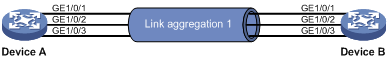
As shown in Figure 1, Device A and Device B are connected by three physical Ethernet links. These physical Ethernet links are combined into an aggregate link called link aggregation 1. The bandwidth of this aggregate link can reach up to the total bandwidth of the three physical Ethernet links. At the same time, the three Ethernet links back up one another. When a physical Ethernet link fails, the traffic previously transmitted on the failed link is switched to the other two links.
Figure 1 Ethernet link aggregation diagram
Basic concepts
Aggregation group, member port, and aggregate interface
An aggregation group is a group of Ethernet interfaces bundled together. These Ethernet interfaces are called member ports of the aggregation group. Each aggregation group has a corresponding logical interface (called an aggregate interface).
Aggregate interfaces include Layer 2 aggregate interfaces and Layer 3 aggregate interfaces.
When you create an aggregate interface, the device automatically creates an aggregation group of the same type and number as the aggregate interface. For example, when you create Layer 2 aggregate interface 1, Layer 2 aggregation group 1 is created.
You can assign Layer 2 Ethernet interfaces or RPR logical interfaces only to a Layer 2 aggregation group. Layer 2 Ethernet interfaces and RPR logical interfaces cannot belong to the same Layer 2 aggregation group. You can assign Layer 3 Ethernet interfaces only to a Layer 3 aggregation group. For more information about RPR logical interfaces, see High Availability Configuration Guide.
The port rate of an aggregate interface equals the total rate of its Selected member ports. Its duplex mode is the same as that of the Selected member ports. For more information about the states of member ports in an aggregation group, see "Aggregation states of member ports in an aggregation group."
Aggregation states of member ports in an aggregation group
A member port in an aggregation group can be in any of the following aggregation states:
· Selected—A Selected port can forward traffic.
· Unselected—An Unselected port cannot forward traffic.
· Individual—An Individual port can forward traffic as a normal physical port. A port is placed in the Individual state when the following conditions exist:
¡ The corresponding aggregate interface is configured as an edge aggregate interface.
¡ The port has not received LACPDUs from its peer port.
Operational key
When aggregating ports, the system automatically assigns each port an operational key based on port information, such as port rate and duplex mode. Any change to this information triggers a recalculation of the operational key.
In an aggregation group, all Selected ports have the same operational key.
Configuration types
Port configurations include attribute configurations and protocol configurations. Attribute configurations of a link aggregation member port affect its aggregation state.
· Attribute configurations—To become a Selected port, a member port must have the same attribute configurations as the aggregate interface. Table 1 describes the attribute configurations.
Attribute configurations made on an aggregate interface are automatically synchronized to all member ports. These configurations are retained on the member ports even after the aggregate interface is deleted.
Any attribute configuration change on a member port might affect the aggregation states of the member ports and running services. The system displays a warning message every time you try to change an attribute configuration setting on a member port.
Table 1 Attribute configurations
|
Feature |
Considerations |
|
Port isolation |
Indicates whether the port has joined an isolation group and which isolation group the port belongs to. |
|
QinQ |
QinQ enable state (enabled/disabled), TPID for VLAN tags, and VLAN transparent transmission. For information about QinQ, see "Configuring QinQ." |
|
VLAN mapping |
VLAN mapping configured on the port. For more information about VLAN mapping, see "Configuring VLAN mapping." |
|
VLAN |
VLAN attribute configurations include: · Permitted VLAN IDs. · PVID. · Link type (trunk, hybrid, or access). · Operating mode (promiscuous, trunk promiscuous, host, or trunk secondary). · IP subnet-based VLAN configuration. · Protocol-based VLAN configuration. · VLAN tagging mode. For information about VLANs, see "Configuring VLANs." |
· Protocol configurations—Protocol configurations of a member port do not affect the aggregation state of the member port. MAC address learning and spanning tree settings are examples of protocol configurations.
|
|
NOTE: The protocol configurations for a member port take effect only when the port leaves its aggregation group. |
Link aggregation modes
An aggregation group operates in one of the following modes:
· Static—Static aggregation is stable. An aggregation group in static mode is called a static aggregation group. The aggregation states of the member ports in a static aggregation group are not affected by the peer ports.
· Dynamic—An aggregation group in dynamic mode is called a dynamic aggregation group. The local system and the peer system automatically maintain the aggregation states of the member ports, which reduces the administrators' workload.
Aggregating links in static mode
Choosing a reference port
When setting the aggregation states of the ports in an aggregation group, the system automatically chooses a member port as the reference port. A Selected port must have the same operational key and attribute configurations as the reference port.
The system chooses a reference port from the member ports that are in up state and have the same attribute configurations as the aggregate interface.
The candidate ports are sorted in the following order:
1. Highest port priority
2. Full duplex/high speed
3. Full duplex/low speed
4. Half duplex/high speed
5. Half duplex/low speed
The candidate port at the top is chosen as the reference port.
· If multiple ports have the same port priority, duplex mode, and speed, the port that has been a Selected port (if any) is chosen. If multiple ports have been Selected ports, the one with the smallest port number is chosen.
· If multiple ports have the same port priority, duplex mode, and speed and none of them has been a Selected port, the port with the smallest port number is chosen.
Setting the aggregation state of each member port
After the reference port is chosen, the system sets the aggregation state of each member port in the static aggregation group.
Figure 2 Setting the aggregation state of a member port in a static aggregation group
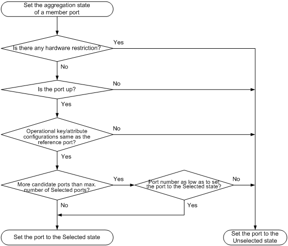
After the limit on Selected ports is reached in a static aggregation group, new member ports in the group are placed in the Unselected state. This mechanism prevents traffic interruption on the existing Selected ports. However, a device reboot can cause the aggregation state of member ports to change.
Any operational key or attribute configuration change might affect the aggregation states of link aggregation member ports.
Aggregating links in dynamic mode
Dynamic aggregation is implemented through IEEE 802.3ad Link Aggregation Control Protocol (LACP).
LACP
LACP uses LACPDUs to exchange aggregation information between LACP-enabled devices.
Each member port in an LACP-enabled aggregation group exchanges information with its peer. When a member port receives an LACPDU, it compares the received information with information received on the other member ports. In this way, the two systems reach an agreement on which ports are placed in the Selected state.
LACP functions
LACP offers basic LACP functions and extended LACP functions, as described in Table 2.
Table 2 Basic and extended LACP functions
|
Category |
Description |
|
Basic LACP functions |
Implemented through the basic LACPDU fields, including the system LACP priority, system MAC address, port priority, port number, and operational key. |
|
Extended LACP functions |
Implemented by extending the LACPDU with new TLV fields. This is how the LACP MAD mechanism of the IRF feature is implemented. If a device supports LACP extensions, it can participate in LACP MAD as either an IRF member device or an intermediate device. For more information about IRF and the LACP MAD mechanism, see Virtual Technologies Configuration Guide. |
LACP operating modes
LACP can operate in active or passive mode.
When LACP is operating in passive mode on a local member port and its peer port, both ports cannot send LACPDUs. When LACP is operating in active mode on either end of a link, both ports can send LACPDUs.
LACP priorities
LACP priorities include system LACP priority and port priority, as described in Table 3. The smaller the priority value, the higher the priority.
|
Type |
Description |
|
System LACP priority |
Used by two peer devices (or systems) to determine which one is superior in link aggregation. In dynamic link aggregation, the system that has higher system LACP priority sets the Selected state of member ports on its side. The system that has lower priority sets port state accordingly. |
|
Port priority |
Determines the likelihood of a member port to be a Selected port on a system. A port with a higher port priority is more likely to become Selected. |
LACP timeout interval
The LACP timeout interval specifies how long a member port waits to receive LACPDUs from the peer port. If a local member port has not received LACPDUs from the peer within the LACP timeout interval, the member port considers the peer as failed.
The LACP timeout interval also determines the LACPDU sending rate of the peer. LACP timeout intervals include the following types:
· Short timeout interval—3 seconds. If you configure the short timeout interval, the peer sends one LACPDU per second.
· Long timeout interval—90 seconds. If you configure the long timeout interval, the peer sends one LACPDU every 30 seconds.
How dynamic link aggregation works
Choosing a reference port
The system chooses a reference port from the member ports that are in up state and have the same attribute configurations as the aggregate interface. A Selected port must have the same operational key and attribute configurations as the reference port.
The local system (the actor) and the peer system (the partner) negotiate a reference port by using the following workflow:
1. The two systems compare their system IDs to determine the system with the smaller system ID.
A system ID contains the system LACP priority and the system MAC address.
a. The two systems compare their LACP priority values.
The lower the LACP priority, the smaller the system ID. If LACP priority values are the same, the two systems proceed to step b.
b. The two systems compare their MAC addresses.
The lower the MAC address, the smaller the system ID.
2. The system with the smaller system ID chooses the port with the smallest port ID as the reference port.
A port ID contains a port priority and a port number. The lower the port priority, the smaller the port ID.
a. The system chooses the port with the lowest priority value as the reference port.
If ports have the same priority, the system proceeds to step b.
b. The system compares their port numbers.
The smaller the port number, the smaller the port ID.
The port with the smallest port number and the same attribute configurations as the aggregate interface is chosen as the reference port.
Setting the aggregation state of each member port
After the reference port is chosen, the system with the smaller system ID sets the state of each member port on its side.
Figure 3 Setting the state of a member port in a dynamic aggregation group
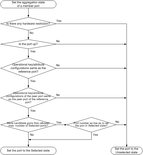
Meanwhile, the system with the higher system ID is aware of the aggregation state changes on the peer system. The system sets the aggregation state of local member ports the same as their peer ports.
When you aggregate interfaces in dynamic mode, follow these guidelines:
· A dynamic link aggregation group preferably chooses full-duplex ports as the Selected ports. The group will choose only one half-duplex port as a Selected port when either of the following conditions exist:
¡ None of the full-duplex ports can be chosen as Selected ports.
¡ Only half-duplex ports exist in the group.
· To ensure stable aggregation and service continuity, do not change the operational key or attribute configurations on any member port.
· When the aggregation state of a local port changes in a dynamic aggregation group, the aggregation state of the peer port also changes.
· After the Selected port limit has been reached, a port joining the aggregation group is placed in the Selected state if it is more eligible than a current Selected port.
Edge aggregate interface
You can configure an edge aggregate interface to connect a network device to a server when the device and the server are two ends of a dynamic aggregate link. During the server reboot process, the device cannot receive LACPDUs from the server (the peer system). This feature enables the aggregation member ports on the device to forward packets from the server during the server reboot process.
Without this feature, the member ports on the device are placed in the Unselected state, and the ports discard packets from the server during the server reboot process.
An edge aggregate interface takes effect only when it is configured on an aggregate interface corresponding to a dynamic aggregation group.
After the server reboot, the device can receive LACPDUs from the server. Then, link aggregation between the device and the server operates correctly.
Load sharing modes for link aggregation groups
In a link aggregation group, traffic can be load shared across the Selected ports based on any of the following modes:
· Per-flow load sharing—Load shares traffic by data flows. The load sharing mode classifies packets into flows and forwards packets of the same flow on the same link. This mode can be one or any combination of the following criteria that classify traffic:
¡ Source or destination MAC address.
¡ Source or destination port number.
¡ Ingress port.
¡ Source or destination IP address.
¡ MPLS label.
· Packet type-based load sharing—Load shares traffic automatically based on packet types (for example, Layer 2 protocol packets, IPv4 packets, MPLS packets, or IPv6 packets).
Ethernet link aggregation configuration task list
|
Tasks at a glance |
|
(Required.) Configuring an aggregation group: |
|
(Optional.) Configuring an aggregate interface: · Setting the description for an aggregate interface · Specifying ignored VLANs for a Layer 2 aggregate interface · Reserving a VLAN interface resource for a Layer 2 aggregate interface · Setting the MTU for a Layer 3 aggregate interface · Setting the minimum and maximum numbers of Selected ports for an aggregation group · Setting the expected bandwidth for an aggregate interface · Configuring an edge aggregate interface |
|
(Optional.) Configuring load balancing for link aggregation group: |
Configuring an aggregation group
This section explains how to configure an aggregation group.
Configuration restrictions and guidelines
When you configure an aggregation group, follow these restrictions and guidelines:
· RPR logical interfaces cannot be assigned to dynamic aggregation groups.
· The device only support two aggregation groups whose member ports are RPR logical interfaces.
· The maximum number of aggregation groups and the maximum number of Selected ports allowed in an aggregation group depend on the location of member ports, as shown in the following matrix:
|
Member port location |
Maximum number of aggregation groups |
Maximum number of Selected ports in an aggregation group |
|
|
Some member ports or the ingress ports of the traffic are on any of these modules. |
· SC interface module: LSU1TGS16SC0 · EA interface modules · EB interface modules · SE interface modules: ¡ LSU1GP24TSE0 ¡ LSU1GP24TXSE0 ¡ LSU1GP48SE0 ¡ LSU1GT48SE0 ¡ LSU1TGS8SE0 ¡ LSU1TGX4SE0 · OAP modules: ¡ LSQ1FWBSC0 ¡ LSQ1LBSC0 ¡ LSQ1NSMSC0 ¡ LSQ1WCMD0 ¡ LSQ2FWBSC0 ¡ LSU1FWCEA0 ¡ LSU3FWCEA0 ¡ LSU3WCMD0 |
128 |
8 |
|
No aggregation group contains member ports on any of these modules. |
1024 |
32 |
|
· You cannot assign a port to a Layer 2 aggregation group if any of the following features are configured on the port:
¡ MAC authentication (see Security Configuration Guide).
¡ Port security (see Security Configuration Guide).
¡ 802.1X (see Security Configuration Guide).
¡ Association between AC and cross connection (see MPLS Configuration Guide).
¡ AC-VSI association (see MPLS Configuration Guide).
· You cannot assign a port to a Layer 3 aggregation group if any of the following features are configured on the port:
¡ Association between AC and cross connection (see MPLS Configuration Guide).
¡ AC-VSI association (see MPLS Configuration Guide).
· An RPR logical interface cannot be assigned to an aggregation group whose corresponding aggregate interface is assigned to an isolation group. For information about isolation groups, see "Configuring port isolation."
· Do not assign a reflector port for port mirroring to an aggregation group. For more information about reflector ports, see Network Management and Monitoring Configuration Guide.
· Deleting an aggregate interface also deletes its aggregation group and causes all member ports to leave the aggregation group.
· You must configure the same aggregation mode on the two ends of an aggregate link.
Configuring a static aggregation group
Configuring a Layer 2 static aggregation group
|
Step |
Command |
Remarks |
|
1. Enter system view. |
system-view |
N/A |
|
2. Create a Layer 2 aggregate interface and enter Layer 2 aggregate interface view. |
interface bridge-aggregation interface-number |
When you create a Layer 2 aggregate interface, the system automatically creates a Layer 2 static aggregation group numbered the same. |
|
3. Exit to system view. |
quit |
N/A |
|
4. Assign an interface to the specified Layer 2 aggregation group. |
a. Enter Layer 2 Ethernet interface view or
RPR logical interface view: b. Assign the interface to the specified Layer 2 aggregation group: |
Repeat these two substeps to assign more Layer 2 Ethernet interfaces or RPR logical interfaces to the aggregation group. You cannot assign Layer 2 Ethernet interfaces and RPR logical interfaces to the same Layer 2 aggregation group. You can assign only two RPR logical interfaces to a Layer 2 aggregation group. |
|
5. (Optional.) Set the port priority for the interface. |
link-aggregation port-priority port-priority |
The default port priority of an interface is 32768. |
Configuring a Layer 3 static aggregation group
|
Step |
Command |
Remarks |
|
1. Enter system view. |
system-view |
N/A |
|
2. Create a Layer 3 aggregate interface and enter Layer 3 aggregate interface view. |
interface route-aggregation interface-number |
When you create a Layer 3 aggregate interface, the system automatically creates a Layer 3 static aggregation group numbered the same. |
|
3. Exit to system view. |
quit |
N/A |
|
4. Assign an interface to the specified Layer 3 aggregation group. |
a. Enter Layer 3 Ethernet interface view: b. Assign the interface to the specified Layer 3 aggregation group: |
Repeat these two substeps to assign more Layer 3 Ethernet interfaces to the aggregation group. |
|
5. (Optional.) Set the port priority for the interface. |
link-aggregation port-priority port-priority |
The default port priority of an interface is 32768. |
Configuring a dynamic aggregation group
To guarantee a successful dynamic aggregation, make sure the peer ports of the ports aggregated at one end are also aggregated. The two ends can automatically negotiate the aggregation state of each member port.
Configuring a Layer 2 dynamic aggregation group
|
Step |
Command |
Remarks |
|
1. Enter system view. |
system-view |
N/A |
|
2. Set the system LACP priority. |
lacp system-priority system-priority |
By default, the system LACP priority is 32768. Changing the system LACP priority might affect the aggregation states of the ports in a dynamic aggregation group. |
|
3. Create a Layer 2 aggregate interface and enter Layer 2 aggregate interface view. |
interface bridge-aggregation interface-number |
When you create a Layer 2 aggregate interface, the system automatically creates a Layer 2 static aggregation group numbered the same. |
|
4. Configure the aggregation group to operate in dynamic mode. |
link-aggregation mode dynamic |
By default, an aggregation group operates in static mode. |
|
5. Exit to system view. |
quit |
N/A |
|
6. Assign an interface to the specified Layer 2 aggregation group. |
a. Enter Layer 2 Ethernet interface view: b. Assign the interface to the specified Layer 2 aggregation group: |
Repeat these two substeps to assign more Layer 2 Ethernet interfaces to the aggregation group. |
|
7. Set the LACP operating mode on the interface. |
· Set the LACP operating
mode to passive: · Set the LACP
operating mode to active: |
By default, LACP is operating in active mode. |
|
8. Set the port priority for the interface. |
link-aggregation port-priority port-priority |
The default setting is 32768. |
|
9. Set the short LACP timeout interval (3 seconds) on the interface. |
lacp period short |
By default, the long LACP timeout interval (90 seconds) is adopted by the interface. To avoid traffic interruption during an ISSU, do not set the short LACP timeout interval before performing the ISSU. For more information about ISSU, see Fundamentals Configuration Guide. |
Configuring a Layer 3 dynamic aggregation group
|
Step |
Command |
Remarks |
|
1. Enter system view. |
system-view |
N/A |
|
2. Set the system LACP priority. |
lacp system-priority system-priority |
By default, the system LACP priority is 32768. Changing the system LACP priority might affect the aggregation states of the ports in the dynamic aggregation group. |
|
3. Create a Layer 3 aggregate interface and enter Layer 3 aggregate interface view. |
interface route-aggregation interface-number |
When you create a Layer 3 aggregate interface, the system automatically creates a Layer 3 static aggregation group numbered the same. |
|
4. Configure the aggregation group to operate in dynamic mode. |
link-aggregation mode dynamic |
By default, an aggregation group operates in static mode. |
|
5. Exit to system view. |
quit |
N/A |
|
6. Assign an interface to the specified Layer 3 aggregation group. |
a. Enter Layer 3 Ethernet interface view: b. Assign the interface to the specified Layer 3 aggregation group: |
Repeat these two substeps to assign more Layer 3 Ethernet interfaces to the aggregation group. |
|
7. Set the LACP operating mode on the interface. |
· Set the LACP operating
mode to passive: · Set the LACP
operating mode to active: |
By default, LACP is operating in active mode. |
|
8. Set the port priority for the interface. |
link-aggregation port-priority port-priority |
The default setting is 32768. |
|
9. Set the short LACP timeout interval (3 seconds) on the interface. |
lacp period short |
By default, the long LACP timeout interval (90 seconds) is adopted by the interface. To avoid traffic interruption during an ISSU, do not set the short LACP timeout interval before performing the ISSU. For more information about ISSU, see Fundamentals Configuration Guide. |
Configuring an aggregate interface
Most of the configurations that can be performed on Layer 2 or Layer 3 Ethernet interfaces can also be performed on Layer 2 or Layer 3 aggregate interfaces.
Setting the description for an aggregate interface
You can set the description for an aggregate interface for administration purposes, for example, describing the purpose of the interface.
To set the description for an aggregate interface:
|
Step |
Command |
Remarks |
|
1. Enter system view. |
system-view |
N/A |
|
2. Enter aggregate interface view. |
· Enter Layer 2
aggregate interface view: · Enter Layer 3 aggregate interface view: |
N/A |
|
3. Set the description for the aggregate interface. |
description text |
By default, the description of an interface is interface-name Interface. |
Specifying ignored VLANs for a Layer 2 aggregate interface
By default, to become Selected ports, the member ports must have the same VLAN permit state and VLAN tagging mode as the corresponding Layer 2 aggregate interface.
The system ignores the permit state and tagging mode of an ignored VLAN when choosing Selected ports.
To specify ignored VLANs for a Layer 2 aggregate interface:
|
Step |
Command |
Remarks |
|
1. Enter system view. |
system-view |
N/A |
|
2. Enter Layer 2 aggregate interface view. |
interface bridge-aggregation interface-number |
N/A |
|
3. Specify ignored VLANs. |
link-aggregation ignore vlan vlan-id-list |
By default, a Layer 2 aggregate interface does not ignore any VLANs. |
Reserving a VLAN interface resource for a Layer 2 aggregate interface
Perform this task to reserve a VLAN interface resource for a Layer 2 aggregate interface whose corresponding aggregation group uses RPR logical interfaces as member ports. The reserved VLAN interface resource is used for traffic forwarding on the RPR logical interfaces.
You must reserve a VLAN interface resource for a Layer 2 aggregate interface after assigning RPR logical interfaces to the corresponding Layer 2 aggregation group. After the resource of a VLAN interface is reserved, you cannot use the vlan and undo vlan commands to create and delete the VLAN.
To reserve a VLAN interface resource for a Layer 2 aggregate interface:
|
Step |
Command |
Remarks |
|
1. Enter system view. |
system-view |
N/A |
|
2. Enter Layer 2 aggregate interface view. |
interface bridge-aggregation interface-number |
N/A |
|
3. Reserve a VLAN interface resource for the Layer 2 aggregate interface. |
rpr reserve-vlan vlan vlan-id |
By default, no VLAN interface resource is reserved for a Layer 2 aggregate interface. You must specify a nonexistent VLAN for the vlan vlan-id option. Otherwise, the configuration fails. |
Setting the MTU for a Layer 3 aggregate interface
The MTU of an interface affects IP packets fragmentation and reassembly on the interface.
To set the MTU for a Layer 3 aggregate interface:
|
Step |
Command |
Remarks |
|
1. Enter system view. |
system-view |
N/A |
|
2. Enter Layer 3 aggregate interface view. |
interface route-aggregation interface-number |
N/A |
|
3. Set the MTU for the Layer 3 aggregate interface. |
mtu size |
The default setting is 1500 bytes. |
Setting the minimum and maximum numbers of Selected ports for an aggregation group
|
IMPORTANT: The minimum and maximum number of Selected ports must be the same for the local and peer aggregation groups. |
The bandwidth of an aggregate link increases as the number of Selected member ports increases. To avoid congestion, you can set the minimum number of Selected ports required for bringing up an aggregate interface.
This minimum threshold setting affects the aggregation states of aggregation member ports and the state of the aggregate interface.
· When the number of member ports eligible to be Selected ports is smaller than the minimum threshold, the following events occur:
¡ The eligible member ports are placed in the Unselected state.
¡ The link layer state of the aggregate interface becomes down.
· When the number of member ports eligible to be Selected ports reaches or exceeds the minimum threshold, the following events occur:
¡ The eligible member ports are placed in the Selected state.
¡ The link layer state of the aggregate interface becomes up.
The maximum number of Selected ports allowed in an aggregation group is limited by either the configured maximum number or hardware limitation, whichever value is smaller.
You can configure backup between two ports by performing the following tasks:
· Assign two ports to an aggregation group.
· Configure 1 as the maximum number of Selected ports allowed in the aggregation group.
Then, only one Selected port is allowed in the aggregation group at any point in time, and the Unselected port acts as a backup port.
To set the minimum and maximum numbers of Selected ports for an aggregation group:
|
Step |
Command |
Remarks |
|
1. Enter system view. |
system-view |
N/A |
|
2. Enter aggregate interface view. |
· Enter Layer 2
aggregate interface view: · Enter Layer 3 aggregate interface view: |
N/A |
|
3. Set the minimum number of Selected ports for the aggregation group. |
link-aggregation selected-port minimum number |
By default, the minimum number of Selected ports for the aggregation group is not specified. |
|
4. Set the maximum number of Selected ports for the aggregation group. |
link-aggregation selected-port maximum number |
By default, the maximum number of Selected ports for an aggregation group depends on hardware limitation. |
Setting the expected bandwidth for an aggregate interface
|
Step |
Command |
Remarks |
|
1. Enter system view. |
system-view |
N/A |
|
2. Enter aggregate interface view. |
· Enter Layer 2
aggregate interface view: · Enter Layer 3 aggregate interface view: |
N/A |
|
3. Set the expected bandwidth for the interface. |
bandwidth bandwidth-value |
By default, the expected bandwidth (in kbps) is the interface baud rate divided by 1000. |
Configuring an edge aggregate interface
When you configure an edge aggregate interface, follow these restrictions and guidelines:
· This configuration takes effect only on the aggregate interface corresponding to a dynamic aggregation group.
· Link-aggregation traffic redirection does not operate correctly on an edge aggregate interface. For more information about link-aggregation traffic redirection, see "Enabling link-aggregation traffic redirection."
To configure an edge aggregate interface:
|
Step |
Command |
Remarks |
|
1. Enter system view. |
system-view |
N/A |
|
2. Enter aggregate interface view. |
· Enter Layer 2
aggregate interface view: · Enter Layer 3 aggregate interface view: |
N/A |
|
3. Configure the aggregate interface as an edge aggregate interface. |
lacp edge-port |
By default, an aggregate interface does not operate as an edge aggregate interface. |
Shutting down an aggregate interface
Shutting down or bringing up an aggregate interface affects the aggregation states and link states of member ports in the corresponding aggregation group as follows:
· When an aggregate interface is shut down, all Selected ports in the corresponding aggregation group become Unselected ports and all member ports go down.
· When an aggregate interface is brought up, the aggregation states of member ports in the corresponding aggregation group are recalculated.
The loopback command cannot be configured on the member port of a shutdown aggregate interface. A port configured with the loopback command cannot be assigned to a shutdown aggregate interface. For more information about the loopback command, see Interface Command Reference.
To shut down an aggregate interface:
|
Step |
Command |
Remarks |
|
1. Enter system view. |
system-view |
N/A |
|
2. Enter aggregate interface view. |
· Enter Layer 2
aggregate interface view: · Enter Layer 3 aggregate interface view: |
N/A |
|
3. Shut down the aggregate interface. |
shutdown |
By default, an aggregate interface is up. |
Restoring the default settings for an aggregate interface
You can restore all configurations on an aggregate interface to the default settings.
To restore the default settings for an aggregate interface:
|
Step |
Command |
|
1. Enter system view. |
system-view |
|
2. Enter aggregate interface view. |
· Enter Layer 2
aggregate interface view: · Enter Layer 3 aggregate interface view: |
|
3. Restore the default settings for the aggregate interface. |
default |
Configuring load sharing for link aggregation groups
This section explains how to configure the load sharing modes for link aggregation groups and how to enable local-first load sharing for link aggregation.
Setting load sharing modes for link aggregation groups
You can set the global or group-specific load sharing mode. The global load sharing mode takes effect on all aggregation groups. A link aggregation group preferentially uses the group-specific load sharing mode. If the group-specific load sharing mode is not available, the group uses the global load sharing mode.
Setting the global link-aggregation load sharing mode
In system view, the switch supports the following load sharing modes and combinations:
· Source IP address.
· Destination IP address.
· Source MAC address.
· Destination MAC address.
· Source IP address and destination IP address.
· Source IP address and source port.
· Destination IP address and destination port.
· Source IP address, source port, destination IP address, and destination port.
· Any combination of ingress port, source MAC address, and destination MAC address.
To set the global link-aggregation load sharing mode:
|
Step |
Command |
Remarks |
|
1. Enter system view. |
system-view |
N/A |
|
2. Set the global link-aggregation load sharing mode. |
link-aggregation global load-sharing mode { destination-ip | destination-mac | destination-port | ingress-port | source-ip | source-mac | source-port } * |
By default, the device load shares traffic automatically based on packet types. |
Setting the group-specific load sharing mode
In Layer 2 aggregate interface view, the switch supports the following load sharing modes and combinations:
· Source IP address.
· Destination IP address.
· Source MAC address.
· Destination MAC address.
· Layer 1 MPLS label.
· Destination IP address and source IP address.
· Destination MAC address and source MAC address.
· Layer 1 MPLS label and Layer 2 MPLS label.
To set the load sharing mode for an aggregation group:
|
Step |
Command |
Remarks |
|
1. Enter system view. |
system-view |
N/A |
|
2. Enter Layer 2 aggregate interface view. |
interface bridge-aggregation interface-number |
N/A |
|
3. Set the load sharing mode for the aggregation group. |
By default, the load sharing mode is the same as the global load sharing mode. |
Enabling local-first load sharing for link aggregation
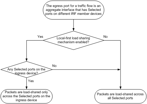
Use local-first load sharing in a multidevice link aggregation scenario to distribute traffic preferentially across member ports on the ingress card or device.
When you aggregate ports on different member devices in an IRF fabric, you can use local-first load sharing to reduce traffic on IRF links, as shown in Figure 4. For more information about IRF, see Virtual Technologies Configuration Guide.
Figure 4 Load sharing for multidevice link aggregation in an IRF fabric
To enable local-first load sharing for link aggregation:
|
Step |
Command |
Remarks |
|
1. Enter system view. |
system-view |
N/A |
|
2. Enable local-first load sharing for link aggregation. |
link-aggregation load-sharing mode local-first |
By default, local-first load sharing for link aggregation is enabled. |
Enabling link-aggregation traffic redirection
Link-aggregation traffic redirection prevents traffic interruption.
When you restart a card that contains Selected ports, this feature redirects traffic of the card to other cards. (In standalone mode.)
When you restart an IRF member device or its card that contains Selected ports, this feature redirects traffic of the IRF member device or card to other IRF member devices or other cards. (In IRF mode.)
Configuration restrictions and guidelines
When you enable link-aggregation traffic redirection, follow these restrictions and guidelines:
· Link-aggregation traffic redirection applies only to dynamic link aggregation groups.
· To prevent traffic interruption, enable link-aggregation traffic redirection on devices at both ends of the aggregate link.
· To prevent packet loss that might occur at a reboot, do not enable spanning tree together with link-aggregation traffic redirection.
· Link-aggregation traffic redirection does not operate correctly on an edge aggregate interface.
· To avoid traffic interruption on Layer 2 dynamic aggregate links after link-aggregation traffic redirection is enabled, make sure the corresponding aggregate interfaces do not have static MAC address entries. For information about MAC address entries, see Layer 2—LAN Switching Configuration Guide.
Configuration procedure
To enable link-aggregation traffic redirection:
|
Step |
Command |
Remarks |
|
1. Enter system view. |
system-view |
N/A |
|
2. Enable link-aggregation traffic redirection. |
link-aggregation lacp traffic-redirect-notification enable |
By default, link-aggregation traffic redirection is disabled. |
Displaying and maintaining Ethernet link aggregation
Execute display commands in any view and reset commands in user view.
|
Task |
Command |
|
Display information for an aggregate interface or multiple aggregate interfaces. |
display interface [ { bridge-aggregation | route-aggregation } [ interface-number ] ] [ brief [ description | down ] ] |
|
Display the local system ID. |
display lacp system-id |
|
Display the global or group-specific link-aggregation load sharing modes. |
display link-aggregation load-sharing mode [ interface [ { bridge-aggregation | route-aggregation } interface-number ] ] |
|
Display detailed link aggregation information for link aggregation member ports. |
display link-aggregation member-port [ interface-list ] |
|
Display summary information about all aggregation groups. |
display link-aggregation summary |
|
Display detailed information about the specified aggregation groups. |
display link-aggregation verbose [ { bridge-aggregation | route-aggregation } [ interface-number ] ] |
|
Clear LACP statistics for the specified link aggregation member ports. |
reset lacp statistics [ interface interface-list ] |
|
Clear statistics for the specified aggregate interfaces. |
reset counters interface [ { bridge-aggregation | route-aggregation } [ interface-number ] ] |
Ethernet link aggregation configuration examples
Layer 2 static aggregation configuration example
Network requirements
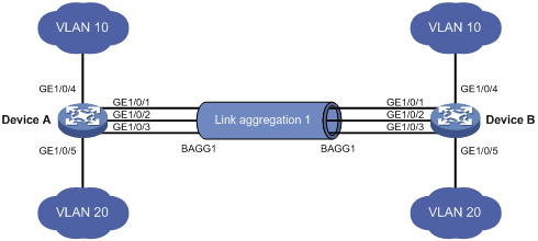
On the network shown in Figure 5, perform the following tasks:
· Configure a Layer 2 static aggregation group on both Device A and Device B.
· Enable VLAN 10 at one end of the aggregate link to communicate with VLAN 10 at the other end.
· Enable VLAN 20 at one end of the aggregate link to communicate with VLAN 20 at the other end.
Configuration procedure
1. Configure Device A:
# Create VLAN 10, and assign port GigabitEthernet 1/0/4 to VLAN 10.
<DeviceA> system-view
[DeviceA] vlan 10
[DeviceA-vlan10] port gigabitethernet 1/0/4
[DeviceA-vlan10] quit
# Create VLAN 20, and assign port GigabitEthernet 1/0/5 to VLAN 20.
[DeviceA] vlan 20
[DeviceA-vlan20] port gigabitethernet 1/0/5
[DeviceA-vlan20] quit
# Create Layer 2 aggregate interface Bridge-Aggregation 1.
[DeviceA] interface bridge-aggregation 1
[DeviceA-Bridge-Aggregation1] quit
# Assign ports GigabitEthernet 1/0/1 through GigabitEthernet 1/0/3 to link aggregation group 1.
[DeviceA] interface gigabitethernet 1/0/1
[DeviceA-GigabitEthernet1/0/1] port link-aggregation group 1
[DeviceA-GigabitEthernet1/0/1] quit
[DeviceA] interface gigabitethernet 1/0/2
[DeviceA-GigabitEthernet1/0/2] port link-aggregation group 1
[DeviceA-GigabitEthernet1/0/2] quit
[DeviceA] interface gigabitethernet 1/0/3
[DeviceA-GigabitEthernet1/0/3] port link-aggregation group 1
[DeviceA-GigabitEthernet1/0/3] quit
# Configure Layer 2 aggregate interface Bridge-Aggregation 1 as a trunk port and assign it to VLANs 10 and 20.
[DeviceA] interface bridge-aggregation 1
[DeviceA-Bridge-Aggregation1] port link-type trunk
[DeviceA-Bridge-Aggregation1] port trunk permit vlan 10 20
[DeviceA-Bridge-Aggregation1] quit
2. Configure Device B in the same way Device A is configured. (Details not shown.)
Verifying the configuration
# Display detailed information about all aggregation groups on Device A.
[DeviceA] display link-aggregation verbose
Loadsharing Type: Shar -- Loadsharing, NonS -- Non-Loadsharing
Port Status: S -- Selected, U -- Unselected, I -- Individual
Flags: A -- LACP_Activity, B -- LACP_Timeout, C -- Aggregation,
D -- Synchronization, E -- Collecting, F -- Distributing,
G -- Defaulted, H -- Expired
Aggregate Interface: Bridge-Aggregation1
Aggregation Mode: Static
Loadsharing Type: Shar
Port Status Priority Oper-Key
--------------------------------------------------------------------------------
GE1/0/1 S 32768 1
GE1/0/2 S 32768 1
GE1/0/3 S 32768 1
The output shows that link aggregation group 1 is a Layer 2 static aggregation group that contains three Selected ports.
Layer 2 dynamic aggregation configuration example
Network requirements
On the network shown in Figure 6, perform the following tasks:
· Configure a Layer 2 dynamic aggregation group on both Device A and Device B.
· Enable VLAN 10 at one end of the aggregate link to communicate with VLAN 10 at the other end.
· Enable VLAN 20 at one end of the aggregate link to communicate with VLAN 20 at the other end.
Configuration procedure
1. Configure Device A:
# Create VLAN 10, and assign the port GigabitEthernet 1/0/4 to VLAN 10.
<DeviceA> system-view
[DeviceA] vlan 10
[DeviceA-vlan10] port gigabitethernet 1/0/4
[DeviceA-vlan10] quit
# Create VLAN 20, and assign the port GigabitEthernet 1/0/5 to VLAN 20.
[DeviceA] vlan 20
[DeviceA-vlan20] port gigabitethernet 1/0/5
[DeviceA-vlan20] quit
# Create Layer 2 aggregate interface Bridge-Aggregation 1, and set the link aggregation mode to dynamic.
[DeviceA] interface bridge-aggregation 1
[DeviceA-Bridge-Aggregation1] link-aggregation mode dynamic
[DeviceA-Bridge-Aggregation1] quit
# Assign ports GigabitEthernet 1/0/1 through GigabitEthernet 1/0/3 to link aggregation group 1.
[DeviceA] interface gigabitethernet 1/0/1
[DeviceA-GigabitEthernet1/0/1] port link-aggregation group 1
[DeviceA-GigabitEthernet1/0/1] quit
[DeviceA] interface gigabitethernet 1/0/2
[DeviceA-GigabitEthernet1/0/2] port link-aggregation group 1
[DeviceA-GigabitEthernet1/0/2] quit
[DeviceA] interface gigabitethernet 1/0/3
[DeviceA-GigabitEthernet1/0/3] port link-aggregation group 1
[DeviceA-GigabitEthernet1/0/3] quit
# Configure Layer 2 aggregate interface Bridge-Aggregation 1 as a trunk port and assign it to VLANs 10 and 20.
[DeviceA] interface bridge-aggregation 1
[DeviceA-Bridge-Aggregation1] port link-type trunk
[DeviceA-Bridge-Aggregation1] port trunk permit vlan 10 20
[DeviceA-Bridge-Aggregation1] quit
2. Configure Device B in the same way Device A is configured. (Details not shown.)
Verifying the configuration
# Display detailed information about all aggregation groups on Device A.
[DeviceA] display link-aggregation verbose
Loadsharing Type: Shar -- Loadsharing, NonS -- Non-Loadsharing
Port Status: S -- Selected, U -- Unselected, I -- Individual
Flags: A -- LACP_Activity, B -- LACP_Timeout, C -- Aggregation,
D -- Synchronization, E -- Collecting, F -- Distributing,
G -- Defaulted, H -- Expired
Aggregate Interface: Bridge-Aggregation1
Aggregation Mode: Dynamic
Loadsharing Type: Shar
System ID: 0x8000, 000f-e267-6c6a
Local:
Port Status Priority Oper-Key Flag
--------------------------------------------------------------------------------
GE1/0/1 S 32768 1 {ACDEF}
GE1/0/2 S 32768 1 {ACDEF}
GE1/0/3 S 32768 1 {ACDEF}
Remote:
Actor Partner Priority Oper-Key SystemID Flag
--------------------------------------------------------------------------------
GE1/0/1 1 32768 1 0x8000, 000f-e267-57ad {ACDEF}
GE1/0/2 2 32768 1 0x8000, 000f-e267-57ad {ACDEF}
GE1/0/3 3 32768 1 0x8000, 000f-e267-57ad {ACDEF}
The output shows that link aggregation group 1 is a Layer 2 dynamic aggregation group that contains three Selected ports.
Layer 2 aggregation load sharing configuration example
Network requirements
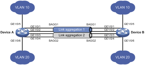
On the network shown in Figure 7, perform the following tasks:
· Configure Layer 2 static aggregation groups 1 and 2 on Device A and Device B, respectively.
· Enable VLAN 10 at one end of the aggregate link to communicate with VLAN 10 at the other end.
· Enable VLAN 20 at one end of the aggregate link to communicate with VLAN 20 at the other end.
· Configure link aggregation groups 1 and 2 to load share traffic across aggregation group member ports:
¡ Configure link aggregation group 1 to load share packets based on source MAC addresses.
¡ Configure link aggregation group 2 to load share packets based on destination MAC addresses.
Configuration procedure
1. Configure Device A:
# Create VLAN 10, and assign the port GigabitEthernet 1/0/5 to VLAN 10.
<DeviceA> system-view
[DeviceA] vlan 10
[DeviceA-vlan10] port gigabitethernet 1/0/5
[DeviceA-vlan10] quit
# Create VLAN 20, and assign the port GigabitEthernet 1/0/6 to VLAN 20.
[DeviceA] vlan 20
[DeviceA-vlan20] port gigabitethernet 1/0/6
[DeviceA-vlan20] quit
# Create Layer 2 aggregate interface Bridge-Aggregation 1.
[DeviceA] interface bridge-aggregation 1
# Configure Layer 2 aggregation group 1 to load share packets based on source MAC addresses.
[DeviceA-Bridge-Aggregation1] link-aggregation load-sharing mode source-mac
[DeviceA-Bridge-Aggregation1] quit
# Assign ports GigabitEthernet 1/0/1 and GigabitEthernet 1/0/2 to link aggregation group 1.
[DeviceA] interface gigabitethernet 1/0/1
[DeviceA-GigabitEthernet1/0/1] port link-aggregation group 1
[DeviceA-GigabitEthernet1/0/1] quit
[DeviceA] interface gigabitethernet 1/0/2
[DeviceA-GigabitEthernet1/0/2] port link-aggregation group 1
[DeviceA-GigabitEthernet1/0/2] quit
# Configure Layer 2 aggregate interface Bridge-Aggregation 1 as a trunk port and assign it to VLAN 10.
[DeviceA] interface bridge-aggregation 1
[DeviceA-Bridge-Aggregation1] port link-type trunk
[DeviceA-Bridge-Aggregation1] port trunk permit vlan 10
[DeviceA-Bridge-Aggregation1] quit
# Create Layer 2 aggregate interface Bridge-Aggregation 2.
[DeviceA] interface bridge-aggregation 2
# Configure Layer 2 aggregation group 2 to load share packets based on destination MAC addresses.
[DeviceA-Bridge-Aggregation2] link-aggregation load-sharing mode destination-mac
[DeviceA-Bridge-Aggregation2] quit
# Assign ports GigabitEthernet 1/0/3 and GigabitEthernet 1/0/4 to link aggregation group 2.
[DeviceA] interface gigabitethernet 1/0/3
[DeviceA-GigabitEthernet1/0/3] port link-aggregation group 2
[DeviceA-GigabitEthernet1/0/3] quit
[DeviceA] interface gigabitethernet 1/0/4
[DeviceA-GigabitEthernet1/0/4] port link-aggregation group 2
[DeviceA-GigabitEthernet1/0/4] quit
# Configure Layer 2 aggregate interface Bridge-Aggregation 2 as a trunk port and assign it to VLAN 20.
[DeviceA] interface bridge-aggregation 2
[DeviceA-Bridge-Aggregation2] port link-type trunk
[DeviceA-Bridge-Aggregation2] port trunk permit vlan 20
[DeviceA-Bridge-Aggregation2] quit
2. Configure Device B in the same way Device A is configured. (Details not shown.)
Verifying the configuration
# Display detailed information about all aggregation groups on Device A.
[DeviceA] display link-aggregation verbose
Loadsharing Type: Shar -- Loadsharing, NonS -- Non-Loadsharing
Port Status: S -- Selected, U -- Unselected, I -- Individual
Flags: A -- LACP_Activity, B -- LACP_Timeout, C -- Aggregation,
D -- Synchronization, E -- Collecting, F -- Distributing,
G -- Defaulted, H -- Expired
Aggregate Interface: Bridge-Aggregation1
Aggregation Mode: Static
Loadsharing Type: Shar
Port Status Priority Oper-Key
--------------------------------------------------------------------------------
GE1/0/1 S 32768 1
GE1/0/2 S 32768 1
Aggregate Interface: Bridge-Aggregation2
Aggregation Mode: Static
Loadsharing Type: Shar
Port Status Priority Oper-Key
--------------------------------------------------------------------------------
GE1/0/3 S 32768 2
GE1/0/4 S 32768 2
The output shows that:
· Link aggregation groups 1 and 2 are both load-shared Layer 2 static aggregation groups.
· Each aggregation group contains two Selected ports.
# Display all the group-specific load sharing modes on Device A.
[DeviceA] display link-aggregation load-sharing mode interface
Bridge-Aggregation1 Load-Sharing Mode:
source-mac address
Bridge-Aggregation2 Load-Sharing Mode:
destination-mac address
The output shows that:
· Link aggregation group 1 load shares packets based on source MAC addresses.
· Link aggregation group 2 load shares packets based on destination MAC addresses.
Layer 2 edge aggregate interface configuration example
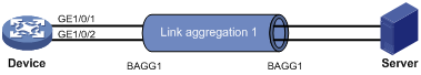
Network requirements
As shown in Figure 8, the device and the server are two ends of a Layer 2 dynamic aggregate link. Configure an edge aggregate interface so that GigabitEthernet 1/0/1 and GigabitEthernet 1/0/2 can forward packets from the server during the server reboot process.
Configuration procedure
1. Configure the device:
# Create Layer 2 aggregate interface Bridge-Aggregation 1, and set the link aggregation mode to dynamic.
[Device] interface bridge-aggregation 1
[Device-Bridge-Aggregation1] link-aggregation mode dynamic
# Configure Layer 2 aggregate interface Bridge-Aggregation 1 as an edge aggregate interface.
[Device-Bridge-Aggregation1] lacp edge-port
[Device-Bridge-Aggregation1] quit
# Assign ports GigabitEthernet 1/0/1 and GigabitEthernet 1/0/2 to link aggregation group 1.
[Device] interface gigabitethernet 1/0/1
[Device-GigabitEthernet1/0/1] port link-aggregation group 1
[Device-GigabitEthernet1/0/1] quit
[Device] interface gigabitethernet 1/0/2
[Device-GigabitEthernet1/0/2] port link-aggregation group 1
[Device-GigabitEthernet1/0/2] quit
2. Configure the server as required. (Details not shown.)
Verifying the configuration
# Display detailed information about all aggregation groups on the device during the server reboot process.
[Device] display link-aggregation verbose
Loadsharing Type: Shar -- Loadsharing, NonS -- Non-Loadsharing
Port Status: S -- Selected, U -- Unselected, I -- Individual
Flags: A -- LACP_Activity, B -- LACP_Timeout, C -- Aggregation,
D -- Synchronization, E -- Collecting, F -- Distributing,
G -- Defaulted, H -- Expired
Aggregate Interface: Bridge-Aggregation1
Aggregation Mode: Dynamic
Loadsharing Type: Shar
System ID: 0x8000, 000f-e267-6c6a
Local:
Port Status Priority Oper-Key Flag
--------------------------------------------------------------------------------
GE1/0/1 I 32768 1 {AG}
GE1/0/2 I 32768 1 {AG}
Remote:
Actor Partner Priority Oper-Key SystemID Flag
--------------------------------------------------------------------------------
GE1/0/1 0 32768 0 0x8000, 0000-0000-0000 {DEF}
GE1/0/2 0 32768 0 0x8000, 0000-0000-0000 {DEF}
The output shows that GigabitEthernet 1/0/1 and GigabitEthernet 1/0/2 are in Individual state when they have not received LACPDUs from the server. Both GigabitEthernet 1/0/1 and GigabitEthernet 1/0/2 can forward packets, which ensures zero packet loss.
Layer 3 static aggregation configuration example
Network requirements
On the network shown in Figure 9, perform the following tasks:
· Configure a Layer 3 static aggregation group on both Device A and Device B.
· Configure IP addresses and subnet masks for the corresponding Layer 3 aggregate interfaces.

Configuration procedure
1. Configure Device A:
# Create Layer 3 aggregate interface Route-Aggregation 1, and configure an IP address and subnet mask for the aggregate interface.
<DeviceA> system-view
[DeviceA] interface route-aggregation 1
[DeviceA-Route-Aggregation1] ip address 192.168.1.1 24
[DeviceA-Route-Aggregation1] quit
# Assign Layer 3 Ethernet interfaces GigabitEthernet 1/0/1 through GigabitEthernet 1/0/3 to aggregation group 1.
[DeviceA] interface gigabitethernet 1/0/1
[DeviceA-GigabitEthernet1/0/1] port link-aggregation group 1
[DeviceA-GigabitEthernet1/0/1] quit
[DeviceA] interface gigabitethernet 1/0/2
[DeviceA-GigabitEthernet1/0/2] port link-aggregation group 1
[DeviceA-GigabitEthernet1/0/2] quit
[DeviceA] interface gigabitethernet 1/0/3
[DeviceA-GigabitEthernet1/0/3] port link-aggregation group 1
[DeviceA-GigabitEthernet1/0/3] quit
2. Configure Device B in the same way Device A is configured. (Details not shown.)
Verifying the configuration
# Display detailed information about all aggregation groups on Device A.
[DeviceA] display link-aggregation verbose
Loadsharing Type: Shar -- Loadsharing, NonS -- Non-Loadsharing
Port Status: S -- Selected, U -- Unselected, I -- Individual
Flags: A -- LACP_Activity, B -- LACP_Timeout, C -- Aggregation,
D -- Synchronization, E -- Collecting, F -- Distributing,
G -- Defaulted, H -- Expired
Aggregate Interface: Route-Aggregation1
Aggregation Mode: Static
Loadsharing Type: Shar
Port Status Priority Oper-Key
--------------------------------------------------------------------------------
GE1/0/1 S 32768 1
GE1/0/2 S 32768 1
GE1/0/3 S 32768 1
The output shows that link aggregation group 1 is a Layer 3 static aggregation group that contains three Selected ports.
Layer 3 dynamic aggregation configuration example
Network requirements
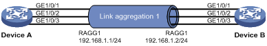
On the network shown in Figure 10, perform the following tasks:
· Configure a Layer 3 dynamic aggregation group on both Device A and Device B.
· Configure IP addresses and subnet masks for the corresponding Layer 3 aggregate interfaces.
Configuration procedure
1. Configure Device A:
# Create Layer 3 aggregate interface Route-Aggregation 1.
<DeviceA> system-view
[DeviceA] interface route-aggregation 1
# Set the link aggregation mode to dynamic.
[DeviceA-Route-Aggregation1] link-aggregation mode dynamic
# Configure an IP address and subnet mask for Route-Aggregation 1.
[DeviceA-Route-Aggregation1] ip address 192.168.1.1 24
[DeviceA-Route-Aggregation1] quit
# Assign Layer 3 Ethernet interfaces GigabitEthernet 1/0/1 through GigabitEthernet 1/0/3 to aggregation group 1.
[DeviceA] interface gigabitethernet 1/0/1
[DeviceA-GigabitEthernet1/0/1] port link-aggregation group 1
[DeviceA-GigabitEthernet1/0/1] quit
[DeviceA] interface gigabitethernet 1/0/2
[DeviceA-GigabitEthernet1/0/2] port link-aggregation group 1
[DeviceA-GigabitEthernet1/0/2] quit
[DeviceA] interface gigabitethernet 1/0/3
[DeviceA-GigabitEthernet1/0/3] port link-aggregation group 1
[DeviceA-GigabitEthernet1/0/3] quit
2. Configure Device B in the same way Device A is configured. (Details not shown.)
Verifying the configuration
# Display detailed information about all aggregation groups on Device A.
[DeviceA] display link-aggregation verbose
Loadsharing Type: Shar -- Loadsharing, NonS -- Non-Loadsharing
Port Status: S -- Selected, U -- Unselected, I -- Individual
Flags: A -- LACP_Activity, B -- LACP_Timeout, C -- Aggregation,
D -- Synchronization, E -- Collecting, F -- Distributing,
G -- Defaulted, H -- Expired
Aggregate Interface: Route-Aggregation1
Aggregation Mode: Dynamic
Loadsharing Type: Shar
System ID: 0x8000, 000f-e267-6c6a
Local:
Port Status Priority Oper-Key Flag
--------------------------------------------------------------------------------
GE1/0/1 S 32768 1 {ACDEF}
GE1/0/2 S 32768 1 {ACDEF}
GE1/0/3 S 32768 1 {ACDEF}
Remote:
Actor Partner Priority Oper-Key SystemID Flag
--------------------------------------------------------------------------------
GE1/0/1 1 32768 1 0x8000, 000f-e267-57ad {ACDEF}
GE1/0/2 2 32768 1 0x8000, 000f-e267-57ad {ACDEF}
GE1/0/3 3 32768 1 0x8000, 000f-e267-57ad {ACDEF}
The output shows that link aggregation group 1 is a Layer 3 dynamic aggregation group that contains three Selected ports.
Layer 3 aggregation load sharing configuration example
Network requirements
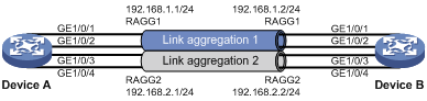
On the network shown in Figure 11, perform the following tasks:
· Configure Layer 3 static aggregation groups 1 and 2 on Device A and Device B, respectively.
· Configure IP addresses and subnet masks for the corresponding Layer 3 aggregate interfaces.
· Configure link aggregation group 1 to load share packets based on source IP addresses.
· Configure link aggregation group 2 to load share packets based on destination IP addresses.
Configuration procedure
1. Configure Device A:
# Create Layer 3 aggregate interface Route-Aggregation 1.
<DeviceA> system-view
[DeviceA] interface route-aggregation 1
# Configure Layer 3 aggregation group 1 to load share packets based on source IP addresses.
[DeviceA-Route-Aggregation1] link-aggregation load-sharing mode source-ip
# Configure an IP address and subnet mask for Layer 3 aggregate interface Route-Aggregation 1.
[DeviceA-Route-Aggregation1] ip address 192.168.1.1 24
[DeviceA-Route-Aggregation1] quit
# Assign Layer 3 Ethernet interfaces GigabitEthernet 1/0/1 and GigabitEthernet 1/0/2 to aggregation group 1.
[DeviceA] interface gigabitethernet 1/0/1
[DeviceA-GigabitEthernet1/0/1] port link-aggregation group 1
[DeviceA-GigabitEthernet1/0/1] quit
[DeviceA] interface gigabitethernet 1/0/2
[DeviceA-GigabitEthernet1/0/2] port link-aggregation group 1
[DeviceA-GigabitEthernet1/0/2] quit
# Create Layer 3 aggregate interface Route-Aggregation 2.
[DeviceA] interface route-aggregation 2
# Configure Layer 3 aggregation group 2 to load share packets based on destination IP addresses.
[DeviceA-Route-Aggregation2] link-aggregation load-sharing mode destination-ip
# Configure an IP address and subnet mask for Layer 3 aggregate interface Route-Aggregation 2.
[DeviceA-Route-Aggregation2] ip address 192.168.2.1 24
[DeviceA-Route-Aggregation2] quit
# Assign Layer 3 Ethernet interfaces GigabitEthernet 1/0/3 and GigabitEthernet 1/0/4 to aggregation group 2.
[DeviceA] interface gigabitethernet 1/0/3
[DeviceA-GigabitEthernet1/0/3] port link-aggregation group 2
[DeviceA-GigabitEthernet1/0/3] quit
[DeviceA] interface gigabitethernet 1/0/4
[DeviceA-GigabitEthernet1/0/4] port link-aggregation group 2
[DeviceA-GigabitEthernet1/0/4] quit
2. Configure Device B in the same way Device A is configured. (Details not shown.)
Verifying the configuration
# Display detailed information about all aggregation groups on Device A.
[DeviceA] display link-aggregation verbose
Loadsharing Type: Shar -- Loadsharing, NonS -- Non-Loadsharing
Port Status: S -- Selected, U -- Unselected, I -- Individual
Flags: A -- LACP_Activity, B -- LACP_Timeout, C -- Aggregation,
D -- Synchronization, E -- Collecting, F -- Distributing,
G -- Defaulted, H -- Expired
Aggregate Interface: Route-Aggregation1
Aggregation Mode: Static
Loadsharing Type: Shar
Port Status Priority Oper-Key
--------------------------------------------------------------------------------
GE1/0/1 S 32768 1
GE1/0/2 S 32768 1
Aggregate Interface: Route-Aggregation2
Aggregation Mode: Static
Loadsharing Type: Shar
Port Status Priority Oper-Key
--------------------------------------------------------------------------------
GE1/0/3 S 32768 2
GE1/0/4 S 32768 2
The output shows that:
· Link aggregation groups 1 and 2 are both load-shared Layer 3 static aggregation groups.
· Each aggregation group contains two Selected ports.
# Display all the group-specific load sharing modes on Device A.
[DeviceA] display link-aggregation load-sharing mode interface
Route-Aggregation1 Load-Sharing Mode:
source-ip address
Route-Aggregation2 Load-Sharing Mode:
destination-ip address
The output shows that:
· Link aggregation group 1 load shares packets based on source IP addresses.
· Link aggregation group 2 load shares packets based on destination IP addresses.
Layer 3 edge aggregate interface configuration example
Network requirements
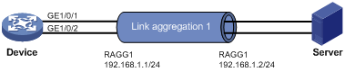
As shown in Figure 12, the device and the server are the two ends of a Layer 3 dynamic aggregate link. Configure an edge aggregate interface so that GigabitEthernet 1/0/1 and GigabitEthernet 1/0/2 can forward packets from the server during the server reboot process.
Configuration procedure
1. Configure the device:
# Create Layer 3 aggregate interface Route-Aggregation 1, and set the link aggregation mode to dynamic.
<Device> system-view
[Device] interface route-aggregation 1
[Device-Route-Aggregation1] link-aggregation mode dynamic
# Configure an IP address and subnet mask for Layer 3 aggregate interface Route-Aggregation 1.
[Device-Route-Aggregation1] ip address 192.168.1.1 24
# Configure Layer 3 aggregate interface Route-Aggregation 1 as an edge aggregate interface.
[Device-Route-Aggregation1] lacp edge-port
[Device-Route-Aggregation1] quit
# Assign Layer 3 Ethernet interfaces GigabitEthernet 1/0/1 and GigabitEthernet 1/0/2 to aggregation group 1.
[Device] interface gigabitethernet 1/0/1
[Device-GigabitEthernet1/0/1] port link-aggregation group 1
[Device-GigabitEthernet1/0/1] quit
[Device] interface gigabitethernet 1/0/2
[Device-GigabitEthernet1/0/2] port link-aggregation group 1
[Device-GigabitEthernet1/0/2] quit
2. Configure the server as required. (Details not shown.)
Verifying the configuration
# Display detailed information about all aggregation groups on the device during the server reboot process.
[Device] display link-aggregation verbose
Loadsharing Type: Shar -- Loadsharing, NonS -- Non-Loadsharing
Port Status: S -- Selected, U -- Unselected, I -- Individual
Flags: A -- LACP_Activity, B -- LACP_Timeout, C -- Aggregation,
D -- Synchronization, E -- Collecting, F -- Distributing,
G -- Defaulted, H -- Expired
Aggregate Interface: Route-Aggregation1
Aggregation Mode: Dynamic
Loadsharing Type: Shar
System ID: 0x8000, 000f-e267-6c6a
Local:
Port Status Priority Oper-Key Flag
--------------------------------------------------------------------------------
GE1/0/1 I 32768 1 {AG}
GE1/0/2 I 32768 1 {AG}
Remote:
Actor Partner Priority Oper-Key SystemID Flag
--------------------------------------------------------------------------------
GE1/0/1 0 32768 0 0x8000, 0000-0000-0000 {DEF}
GE1/0/2 0 32768 0 0x8000, 0000-0000-0000 {DEF}
The output shows that GigabitEthernet 1/0/1 and GigabitEthernet 1/0/2 are in Individual state when they have not received LACPDUs from the server. Both GigabitEthernet 1/0/1 and GigabitEthernet 1/0/2 can forward packets, which ensures zero packet loss.