- Table of Contents
- Related Documents
-
| Title | Size | Download |
|---|---|---|
| 01-VXLAN configuration | 696.45 KB |
VXLAN tunnel establishment and assignment
Assignment of traffic to VXLANs
Configuring basic VXLAN features
Assigning a VXLAN tunnel to a VXLAN
Mapping an Ethernet service instance to a VSI
Enabling VXLAN local MAC change logging
Configuring static remote-MAC address entries
Enabling remote-MAC address learning
Configuring a multicast-mode VXLAN
Confining unknown-unicast floods to the local site
Configuring the destination UDP port number of VXLAN packets
Configuring VXLAN packet check
Enabling ARP flood suppression
Specifying a VTEP group to provide gateway services for VXLANs
Configuring VXLAN packet statistics
Displaying and maintaining VXLANs
Unicast-mode VXLAN configuration example
Multicast-mode VXLAN configuration example
Configuring the VTEP as an ENDS
Configuring the VTEP as an ENDC
Displaying and maintaining ENDP
VXLAN IS-IS configuration task list
Specifying a reserved VXLAN for VXLAN IS-IS
Enabling VXLAN autonegotiation to automate VXLAN tunnel assignment
Enabling MAC advertisement through VXLAN IS-IS
Configuring the DED priority and CSNP interval
Enabling adjacency change logging
Configuring Graceful Restart for VXLAN IS-IS
Increasing the maximum number of MAC entries in an LSP
Displaying and maintaining VXLAN IS-IS
VXLAN IS-IS configuration example
Configuring the VTEP as an OVSDB VTEP
Establishing an OVSDB connection with a controller
Establishing an active SSL connection to a controller
Listening for SSL connection requests from controllers
Establishing an active TCP connection to a controller
Listening for TCP connection requests from controllers
Specifying a global source address for VXLAN tunnels
Disabling remote-MAC address learning
Enabling flood proxy on all multicast VXLAN tunnels
OVSDB VTEP configuration examples
Unicast-mode VXLAN configuration example
Flood proxy configuration example
Virtual eXtensible LAN (VXLAN) is a MAC-in-UDP technology that provides Layer 2 connectivity between distant network sites across an IP network. VXLAN is typically used in data centers for multitenant services.
VXLAN provides the following benefits:
· Support for more virtual switched domains than VLANs—Each VXLAN is uniquely identified by a 24-bit VXLAN ID. The total number of VXLANs can reach 16777216 (224). This specification makes VXLAN a better choice than 802.1Q VLAN to isolate traffic for VMs.
· Easy deployment and maintenance—VXLAN requires deployment only on the edge devices of the transport network. Devices in the transport network perform typical Layer 3 forwarding.
The device supports only IPv4-based VXLAN. IPv6-based VXLAN is not supported.
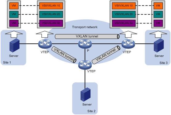
VXLAN network model
As show in Figure 1, the transport edge devices assign VMs to different VXLANs, and then forward traffic between sites for VMs by using VXLAN tunnels.
The transport edge devices are VXLAN tunnel endpoints (VTEP). They can be servers that host VMs or independent network devices.
An H3C VTEP uses VSIs and VXLAN tunnels to provide VXLAN services.
· VSI—A virtual switching instance is a virtual Layer 2 switched domain. Each VSI provides switching services only for one VXLAN. VSIs learn MAC addresses and forward frames independently of one another. VMs in different sites have Layer 2 connectivity if they are in the same VXLAN.
· VXLAN tunnel—Logical point-to-point tunnels between VTEPs over the transport network. Each VXLAN tunnel can trunk multiple VXLANs.
VTEPs encapsulate VXLAN traffic in the VXLAN, outer UDP, and outer IP headers. The devices in the transport network forward VXLAN traffic only based on the outer IP header.
Figure 1 VXLAN network model
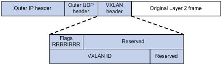
VXLAN packet format
As shown in Figure 2, a VTEP encapsulates a frame in the following headers:
· 8-byte VXLAN header—VXLAN information for the frame.
? Flags—If the I bit is 1, the VXLAN ID is valid. If the I bit is 0, the VXLAN ID is invalid. All other bits are reserved and set to 0.
? 24-bit VXLAN ID—Identifies the VXLAN of the frame. It is also called the virtual network identifier (VNI).
· 8-byte outer UDP header for VXLAN—The default VXLAN UDP port number is 4789.
· 20-byte outer IP header—Valid addresses of VTEPs or VXLAN multicast groups on the transport network. Devices in the transport network forward VXLAN packets based on the outer IP header.
Figure 2 VXLAN packet format
Working mechanisms
The VTEP uses the following process to forward an inter-site frame:
1. Discovers remote VTEPs, establishes VXLAN tunnels, and assigns the VXLAN tunnels to VXLANs.
2. Assigns the frame to its matching VXLAN if the frame is sent between sites.
3. Performs MAC learning on the VXLAN's VSI.
4. Forwards the frame.
This section describes this process in detail. For intra-site frames in a VSI, the system performs typical Layer 2 forwarding and processes 802.1Q VLAN tags, as described in "Access modes of VSIs."
VXLAN tunnel establishment and assignment
To provide Layer 2 connectivity for a VXLAN between two sites, you must create a VXLAN tunnel between the sites and assign the tunnel to the VXLAN.
VXLAN tunnel establishment
VXLAN supports manual and automatic VXLAN tunnel establishment.
· Manual creation—Manually create a VXLAN tunnel interface, and specify the tunnel source and destination IP addresses on the peer VTEPs.
· Automatic creation—Configure the Enhanced Neighbor Discovery Protocol (ENDP) to automatically discover VTEPs and set up VXLAN tunnels. For more information about ENDP, see "Configuring ENDP."
VXLAN tunnel assignment
VXLAN supports manual and automatic VXLAN tunnel assignment.
· Manual assignment—Manually assign VXLAN tunnels to VXLANs.
· Automatic assignment—Run VXLAN IS-IS to advertise VXLAN IDs over all VXLAN tunnels between VTEPs. Two VTEPs automatically assign the VXLAN tunnel between them to a VXLAN if both of them have the VXLAN ID.
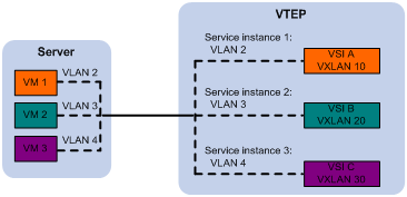
Assignment of traffic to VXLANs
Traffic from the local site to a remote site
The VTEP uses an Ethernet service instance to match a list of VLANs on a site-facing interface. The VTEP assigns customer traffic from the VLANs to a VXLAN by mapping the Ethernet service instance to a VSI. An Ethernet service instance is identical to an attachment circuit (AC) in L2VPN.
As shown in Figure 3, Ethernet service instance 1 matches VLAN 2 and is mapped to VSI A (VXLAN 10). When a frame from VLAN 2 arrives, the VTEP assigns the frame to VXLAN 10, and looks up VSI A's MAC address table for the outgoing interface.
Figure 3 Identifying traffic from the local site
Traffic from a remote site to the local site
When a frame arrives at a VXLAN tunnel, the VTEP uses the VXLAN ID in the frame to identify its VXLAN.
MAC learning
The VTEP performs source MAC learning on the VSI as a Layer 2 switch.
· For traffic from the local site to the remote site, the VTEP learns the source MAC address before VXLAN encapsulation.
· For traffic from the remote site to the local site, the VTEP learns the source MAC address after removing the VXLAN header.
The VTEP can also use VXLAN IS-IS in the control plane to advertise local MAC reachability information to remote sites and learn MAC reachability information from remote sites.
A VSI's MAC address table includes the following types of MAC address entries:
· Local MAC—Dynamic MAC entries learned from the local site. The outgoing interfaces are site-facing interfaces on which the MAC addresses are learned. VXLAN does not support manual local MAC entries.
· Remote MAC—Include static and dynamic MAC entries. The outgoing interfaces for the MAC addresses are VXLAN tunnel interfaces.
? Static—Include manually added MAC entries and VXLAN IS-IS advertised MAC entries.
? Dynamic—MAC entries learned in the data plane from incoming traffic on VXLAN tunnels. The learned MAC addresses are contained in the inner Ethernet header.
For a remote address, the manual static entry has higher priority than dynamic and advertised entries. Dynamic and advertised entries have the same priority and can overwrite each other.
Traffic forwarding
The VTEP uses the following processes to forward traffic:
· Unicast process—Applies to destination-known unicast traffic.
· Flood process—Applies to multicast, broadcast, and unknown unicast traffic.
When the VTEP forwards VXLAN traffic, it processes the 802.1q tag in the inner Ethernet header depending on the VSI access mode (VLAN or Ethernet mode). In VLAN access mode, sites can use different VLANs to provide the same service. For more information, see "Access modes of VSIs."
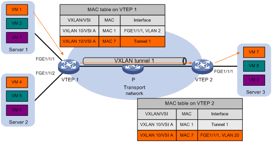
Unicast
The following process (see Figure 4) applies to a known unicast frame between sites:
1. The source VTEP encapsulates the Ethernet frame in the VXLAN/UDP/IP header.
In the outer IP header, the source IP address is the source VTEP's VXLAN tunnel source IP address. The destination IP address is the VXLAN tunnel destination IP address.
2. The source VTEP forwards the encapsulated packet out of the outgoing VXLAN tunnel interface found in the VSI's MAC address table.
3. The intermediate transport devices (P devices) forward the frame to the destination VTEP by using the outer IP header.
4. The destination VTEP removes the headers on top of the inner Ethernet frame. It then performs MAC address table lookup in the VXLAN's VSI to forward the frame out of the matching outgoing interface.
Flood
The VTEP floods a broadcast, multicast, or unknown unicast frame to all site-facing interfaces and VXLAN tunnels in the VXLAN, except for the incoming interface.
VXLAN supports the following modes for flood traffic:
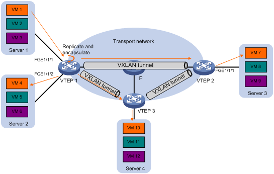
· Unicast mode—Also called head-end replication. The source VTEP replicates the flood frame, and then sends one replica to the destination IP address of each VXLAN tunnel in the VXLAN. See Figure 5.
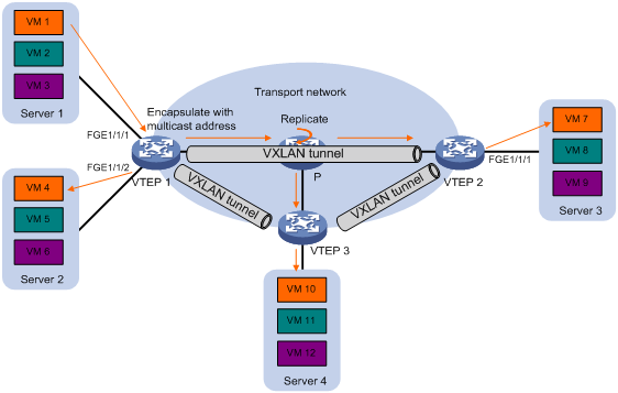
· Multicast mode—Also called tandem replication. The source VTEP sends the flood frame in a multicast VXLAN packet destined for a multicast group address. Transport network devices replicate and forward the packet to remote VTEPs based on their multicast forwarding entries. See Figure 6.
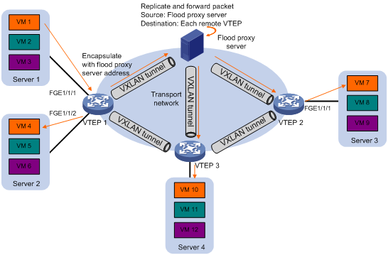
· Flood proxy mode—The source VTEP sends the flood frame in a VXLAN packet over a VXLAN tunnel to a flood proxy server. The flood proxy server replicates and forwards the packet to each remote VTEP through its VXLAN tunnels. See Figure 7.
The flood proxy mode applies to VXLANs that have many sites. This mode reduces flood traffic in the transport network without using a multicast protocol. To use a flood proxy server, you must set up a VXLAN tunnel to the server on each VTEP.
|
|
NOTE: The flood proxy mode is typically used in SDN transport networks that have a flood proxy server. For VTEPs to forward packets based on the MAC address table issued by an SDN controller, you must perform the following tasks on the VTEPs: · Disable remote-MAC address learning by using the vxlan tunnel mac-learning disable command. · Configure an OpenFlow instance for the VXLAN. |
Each destination VTEP floods the inner Ethernet frame to all the site-facing interfaces in the VXLAN. To avoid loops, the destination VTEPs do not flood the frame to VXLAN tunnels.
Access modes of VSIs
The access mode of a VSI determines how the VTEP processes the 802.1Q VLAN tags in the Ethernet frames.
· VLAN access mode—Ethernet frames received from or sent to the local site must contain 802.1Q VLAN tags.
? For an Ethernet frame received from the local site, the VTEP removes all its 802.1Q VLAN tags before forwarding the frame.
? For an Ethernet frame destined for the local site, the VTEP adds 802.1Q VLAN tags to the frame before forwarding the frame.
In VLAN access mode, VXLAN packets sent between sites do not contain 802.1Q VLAN tags. You can use different 802.1Q VLANs to provide the same service in different sites.
· Ethernet access mode—The VTEP does not process the 802.1Q VLAN tags of Ethernet frames received from or sent to the local site.
? For an Ethernet frame received from the local site, the VTEP forwards the frame with the 802.1Q VLAN tags intact.
? For an Ethernet frame destined for the local site, the VTEP forwards the frame without adding 802.1Q VLAN tags.
In Ethernet access mode, VXLAN packets sent between VXLAN sites contain 802.1Q VLAN tags. You must use the same VLAN to provide the same service between sites.
ARP flood suppression
ARP flood suppression reduces ARP request broadcasts by enabling the VTEP to reply to ARP requests on behalf of VMs.
As shown in Figure 8, this feature snoops ARP packets to populate the ARP flood suppression table with local and remote MAC addresses. If an ARP request has a matching entry, the VTEP replies to the request on behalf of the VM. If no match is found, the VTEP floods the request to both local and remote sites.
Figure 8 ARP flood suppression

ARP flood suppression uses the following workflow:
1. VM 1 sends an ARP request to obtain the MAC address of VM 7.
2. VTEP 1 creates a suppression entry for VM 1, and floods the ARP request in the VXLAN.
3. VTEP 2 and VTEP 3 de-encapsulate the ARP request. The VTEPs create a suppression entry for VM 1, and broadcast the request in the local site.
4. VM 7 sends an ARP reply.
5. VTEP 2 creates a suppression entry for VM 7 and forwards the ARP reply to VTEP 1.
6. VTEP 1 de-encapsulates the ARP reply, creates a suppression entry for VM 7, and forwards the ARP reply to VM 1.
7. VM 4 sends an ARP request to obtain the MAC address of VM 1 or VM 7.
8. VTEP 1 creates a suppression entry for VM 4 and replies to the ARP request.
9. VM 10 sends an ARP request to obtain the MAC address of VM 1.
10. VTEP 3 creates a suppression entry for VM 10 and replies to the ARP request.
Protocols and standards
RFC 7047, Virtual eXtensible Local Area Network (VXLAN): A Framework for Overlaying Virtualized Layer 2 Networks over Layer 3 Networks
VXLAN configuration task list
|
Tasks at a glance |
Remarks |
|
(Required.) Creating a VXLAN on a VSI |
N/A |
|
(Required.) Configuring a VXLAN tunnel |
N/A |
|
(Required.) Assigning a VXLAN tunnel to a VXLAN |
To extend a VXLAN to remote sites, you must assign VXLAN tunnels to the VXLAN. |
|
(Required.) Mapping an Ethernet service instance to a VSI |
Perform this task to assign customer traffic to VXLANs. |
|
(Optional.) Managing MAC address entries |
You can add static remote MAC addresses. When network attacks occur, disable remote-MAC address learning to prevent the device from learning incorrect remote MAC addresses. |
|
(Optional.) Configuring a multicast-mode VXLAN |
By default, the VTEP floods VXLAN traffic in unicast mode. If the network is multicast dense, configure the VTEP to flood VXLAN traffic in multicast mode. |
|
(Optional.) Confining unknown-unicast floods to the local site |
Perform this task to suppress unknown-unicast floods to the transport network. |
|
(Optional.) Configuring the destination UDP port number of VXLAN packets |
N/A |
|
(Optional.) Configuring VXLAN packet check |
Perform this task to check incoming VXLAN packets, including the following items: · UDP checksum. · 802.1Q VLAN tags in the inner Ethernet header. |
|
(Optional.) Enabling ARP flood suppression |
N/A |
|
(Optional.) Specifying a VTEP group to provide gateway services for VXLANs |
N/A |
|
(Optional.) Configuring VXLAN packet statistics |
N/A |
Creating a VXLAN on a VSI
|
Command |
Remarks |
|
|
1. Enter system view. |
system-view |
N/A |
|
2. Enable L2VPN. |
l2vpn enable |
By default, L2VPN is disabled. |
|
3. Create a VSI and enter VSI view. |
vsi vsi-name |
By default, no VSIs are created. |
|
4. (Optional.) Configure a VSI description. |
description text |
By default, a VSI does not have description. |
|
5. Enable the VSI. |
undo shutdown |
By default, a VSI is enabled. |
|
6. Create a VXLAN and enter VXLAN view. |
vxlan vxlan-id |
By default, no VXLANs are created. You can create only one VXLAN on a VSI. The VXLAN ID must be unique for each VSI. |
Configuring a VXLAN tunnel
For two sites to communicate through VXLAN, you can manually configure a VXLAN tunnel or configure ENDP to automatically establish a VXLAN tunnel. For more information about ENDP, see "Configuring ENDP."
This task provides basic VXLAN tunnel configuration. For more information about tunneling configuration and commands, see Layer 3—IP Services Configuration Guide and Layer 3—IP Services Command Reference.
To configure a VXLAN tunnel:
|
Step |
Command |
Remarks |
|
1. Enter system view. |
system-view |
N/A |
|
2. Specify a global source address for VXLAN tunnels. |
tunnel global source-address ipv4-address |
By default, no global source address is specified for VXLAN tunnels. If you do not specify a source interface or source address for a VXLAN tunnel, the tunnel uses the global source address. |
|
3. Create a VXLAN tunnel interface and enter tunnel interface view. |
interface tunnel tunnel-number mode vxlan |
By default, no tunnel interfaces exist. The endpoints of a tunnel must use the same tunnel mode. |
|
4. Specify a source IP address or source interface for the tunnel. |
source { ipv4-address | interface-type interface-number } |
By default, no source IP address or source interface is specified for a tunnel. This step specifies the source IP address in the outer IP header of tunneled VXLAN packets. If an interface is specified, its primary IP address is used. For a multicast-mode VXLAN, the source IP address cannot be a loopback address, and the source interface cannot be a loopback interface. |
|
5. Specify a destination IP address for the tunnel. |
destination ipv4-address |
By default, no destination IP address is specified for a tunnel. Specify the remote VTEP's IP address. This IP address will be the destination IP address in the outer IP header of tunneled VXLAN packets. |
|
6. (Optional.) Enable BFD on the tunnel. |
tunnel bfd enable destination-mac mac-address |
By default, BFD is disabled on a tunnel. For BFD sessions to come up, you must also reserve a VXLAN by using the reserved vxlan command. The VTEPs send BFD single-hop control packets to detect the connectivity of VXLAN tunnels. The VTEPs periodically send control packets to each other through the VXLAN tunnel. A VTEP sets the tunnel state to Defect if it has not received control packets from the remote end for five seconds. In this situation, the tunnel interface state is still Up. The tunnel state will change from Defect to Up if the VTEP can receive BFD control packets again. |
Assigning a VXLAN tunnel to a VXLAN
To provide Layer 2 connectivity for a VXLAN between two sites, you must assign the VXLAN tunnel between the sites to the VXLAN.
You can assign multiple VXLAN tunnels to a VXLAN, and configure a VXLAN tunnel to trunk multiple VXLANs. For a unicast-mode VXLAN, the system floods unknown unicast, multicast, and broadcast traffic to each tunnel associated with the VXLAN.
This section describes the manual VXLAN tunnel assignment. For information about automatic VXLAN tunnel assignment through VXLAN IS-IS, see "Configuring VXLAN IS-IS."
To assign a VXLAN tunnel to a VXLAN:
|
Step |
Command |
Remarks |
|
1. Enter system view. |
system-view |
N/A |
|
2. Enter VSI view. |
vsi vsi-name |
N/A |
|
3. Enter VXLAN view. |
vxlan vxlan-id |
N/A |
|
4. Assign a VXLAN tunnel to the VXLAN. |
tunnel tunnel-number [ flooding-proxy ] |
By default, a VXLAN does not contain any VXLAN tunnels. For full Layer 2 connectivity in the VXLAN, make sure the VXLAN contains the VXLAN tunnel between each pair of sites in the VXLAN. Enable flood proxy on the tunnel for the VTEP to send flood traffic to the flood proxy server. The flood proxy server replicates and forwards flood traffic to remote VTEPs. |
Mapping an Ethernet service instance to a VSI
An Ethernet service instance matches a list of VLANs on a site-facing interface. The VTEP assigns customer traffic from the VLANs to a VXLAN by mapping the Ethernet service instance to a VSI.
When you configure Ethernet service instances on an interface, follow these guidelines:
· The match criterion in each Ethernet service instance on an interface must be unique. For example, you cannot configure the encapsulation tagged command in one Ethernet service instance if another Ethernet service instance already contains this command. You cannot use the encapsulation s-vid vlan-id command to specify the same 802.1Q VLAN ID for any two Ethernet service instances on the interface.
· An Ethernet service instance can contain only one match criterion. To change the match criterion, you must remove the original criterion first. When you remove the match criterion in an Ethernet service instance, the mapping between the service instance and the VSI is removed automatically.
· To forward the multicast traffic from a VLAN on the interface, make sure an Ethernet service instance contains the VLAN ID. The interface cannot forward a multicast packet that does not match any Ethernet service instance.
If an Ethernet service instance contains the encapsulation default match criterion, traffic is matched as follows:
· The service instance matches any frames if it is the only instance on the interface.
· The service instance matches frames that do not match any other service instance if multiple instances exist on the interface.
To map an Ethernet service instance to a VSI:
|
Step |
Command |
Remarks |
|
1. Enter system view. |
system-view |
N/A |
|
2. Enter Layer 2 Ethernet interface view or Layer 2 aggregate interface view. |
· interface interface-type interface-number · interface bridge-aggregation interface-number |
N/A |
|
3. Create an Ethernet service instance and enter Ethernet service instance view. |
service-instance instance-id |
By default, no Ethernet service instances exist. Ethernet service instances and EVB cannot work together. Do not configure both features on an interface. For more information about EVB, see EVB Configuration Guide. Ethernet service instances for VXLAN cannot work together with Ethernet service instances for MPLS L2VPN or VPLS. Do not configure both types of service instances on an interface. For more information about MPLS L2VPN and VPLS, see MPLS Configuration Guide. |
|
4. Configure a frame match criterion. |
· Match any frames: · Match any 802.1Q tagged or untagged frames: · Match frames tagged with the specified outer 802.1Q
VLAN ID: |
By default, an Ethernet service instance does not contain frame match criteria. Make sure the matching VLANs are not permitted on EVB-enabled interfaces on the device. |
|
5. Map the Ethernet service instance to a VSI. |
xconnect vsi vsi-name [ access-mode { ethernet | vlan } ] |
By default, an Ethernet service instance is not mapped to any VSI. If the Ethernet service instance uses the default, tagged, or untagged frame match criterion, the access mode set by this command does not take effect. The VSI uses Ethernet access mode to process traffic. |
Managing MAC address entries
With VXLAN, local MAC addresses can only be learned dynamically. You cannot manually add local MAC addresses. However, you can log the local MAC changes.
Remote MAC address entries include the following types:
· Manually created static entries.
· Dynamic entries learned in the data plane.
· Entries advertised in the control plane through VXLAN IS-IS.
For more information about VXLAN IS-IS MAC address advertisement, see "Configuring VXLAN IS-IS."
Enabling VXLAN local MAC change logging
Local-MAC change logging enables the VXLAN module to send a log message to the information center when a local MAC address is added or removed.
With the information center, you can set log message filtering and output rules, including output destinations. For more information about configuring the information center, see Network Management and Monitoring Configuration Guide.
To enable local MAC change logging:
|
Step |
Command |
Remarks |
|
1. Enter system view. |
system-view |
N/A |
|
2. Enable local MAC change logging. |
vxlan local-mac report |
By default, VXLAN local MAC change logging is disabled. |
Configuring static remote-MAC address entries
|
Step |
Command |
Remarks |
|
1. Enter system view. |
system-view |
N/A |
|
2. Add a static remote entry. |
mac-address static mac-address interface tunnel tunnel-number vsi vsi-name |
By default, VXLAN VSIs do not have static remote-MAC address entries. For the setting to take effect, make sure the VSI's VXLAN has been created and specified on the VXLAN tunnel. |
Enabling remote-MAC address learning
|
Step |
Command |
Remarks |
|
1. Enter system view. |
system-view |
N/A |
|
2. Enable remote-MAC address learning. |
undo vxlan tunnel mac-learning disable |
By default, remote-MAC address learning is enabled. When network attacks occur, disable remote-MAC address learning to prevent the device from learning incorrect remote MAC addresses. |
Configuring a multicast-mode VXLAN
For a multicast-mode VXLAN to flood traffic, you must perform the following tasks in addition to multicast-mode configuration:
· Enable IP multicast routing on all VTEPs and transport network devices.
· Configure IGMP and a multicast routing protocol on transport network devices. Because a VTEP can be both a multicast source and multicast group member, H3C recommends that you use BIDIR-PIM.
|
|
NOTE: A multicast-mode VXLAN does not use unicast routing tunnels to forward flood traffic when its multicast routing tunnels are down. |
To configure a multicast-mode VXLAN:
|
Step |
Command |
Remarks |
|
1. Enter system view. |
system-view |
N/A |
|
2. Enable multicast routing. |
multicast routing |
By default, multicast routing is disabled. |
|
3. Return to system view. |
quit |
N/A |
|
4. Enter VSI view. |
vsi vsi-name |
N/A |
|
5. Enter VXLAN view. |
vxlan vxlan-id |
N/A |
|
6. Assign a multicast group address for flood traffic, and specify a source IP address for multicast VXLAN packets. |
group group-address source source-address |
By default, a VXLAN uses unicast mode for flood traffic. No multicast group address or source IP address is specified for multicast VXLAN packets. You must assign all VTEPs in a multicast-mode VXLAN to the same multicast group. For VXLANs that use the same multicast group address, you must configure the same source IP address for their multicast VXLAN packets. For multicast traffic to be forwarded correctly, you must use the source IP address of an up VXLAN tunnel as the source IP address of multicast VXLAN packets. |
|
7. Enter the view of the interface that provides the source IP address for multicast VXLAN packets. |
interface interface-type interface-number |
The source source-address option in the group command specifies the source IP address of multicast VXLAN packets. |
|
8. Enable the IGMP host function. |
igmp host enable |
By default, the IGMP host function is disabled on an interface. The IGMP host function enables the interface to send IGMP reports in response to IGMP queries before it can receive traffic from the multicast group. |
Confining unknown-unicast floods to the local site
By default, the VTEP floods unknown unicast frames received from the local site to the following interfaces in the frame's VXLAN:
· All site-facing interfaces except for the incoming interface.
· All VXLAN tunnel interfaces.
To confine unknown-unicast floods to site-facing interfaces for a VXLAN:
|
Step |
Command |
Remarks |
|
|
1. Enter system view. |
system-view |
N/A |
|
|
2. Enter VSI view. |
vsi vsi-name |
N/A |
|
|
3. Disable the VSI to flood unknown unicast traffic to VXLAN tunnel interfaces. |
flooding disable |
By default, unknown unicast traffic is flooded to all interfaces in the VXLAN, except for the incoming interface. |
|
|
4. (Optional.) Enable selective flood for a MAC address. |
selective-flooding mac-address mac-address |
By default, selective flood is disabled. Use this feature to exclude a remote MAC address from the flood suppression done by using the flooding disable command. The VTEP will flood the frames destined for the specified MAC address to remote sites when unknown-unicast floods are confined to the local site. |
|
Configuring the destination UDP port number of VXLAN packets
|
Step |
Command |
Remarks |
|
1. Enter system view. |
system-view |
N/A |
|
2. Configure a destination UDP port for VXLAN packets. |
vxlan udp-port port-number |
By default, the destination UDP port number is 4789 for VXLAN packets. You must configure the same destination UDP port number on all VTEPs in a VXLAN. |
Configuring VXLAN packet check
The device can check the UDP checksum and 802.1Q VLAN tags of each received VXLAN packet.
· UDP checksum check—The device always sets the UDP checksum of VXLAN packets to zero. For compatibility with third-party devices, a VXLAN packet can pass the check if its UDP checksum is zero or correct. If its UDP checksum is incorrect, the VXLAN packet fails the check and is dropped.
· VLAN tag check—The device checks the inner Ethernet header of each VXLAN packet for 802.1Q VLAN tags. If the header contains 802.1Q VLAN tags, the device drops the packet.
If a remote VTEP uses the Ethernet access mode for an Ethernet service instance, its VXLAN packets might contain 802.1Q VLAN tags. To prevent the local VTEP from dropping the VXLAN packets, do not execute the vxlan invalid-vlan-tag discard command on the local VTEP.
The access mode of an Ethernet service instance is configurable by using the xconnect vsi command.
To configure VXLAN packet check:
|
Step |
Command |
Remarks |
|
1. Enter system view. |
system-view |
N/A |
|
2. Enable the VTEP to drop VXLAN packets that fail UDP checksum check. |
vxlan invalid-udp-checksum discard |
By default, the VTEP does not check the UDP checksum of VXLAN packets. |
|
3. Enable the VTEP to drop VXLAN packets that have 802.1Q VLAN tags in the inner Ethernet header. |
vxlan invalid-vlan-tag discard |
By default, the VTEP does not check the inner Ethernet header for 802.1Q VLAN tags. |
Enabling ARP flood suppression
Use ARP flood suppression to reduce ARP request broadcasts.
The aging timer is fixed at 25 minutes for ARP flood suppression entries. If the suppression table is full, the VTEP stops learning new entries. For the VTEP to learn new entries, you must wait old entries to age out, or use the reset arp suppression command to clear the table.
If the flooding disable command is configured, set the MAC aging timer to a higher value than the aging timer for ARP flood suppression entries on all VTEPs. This setting prevents the traffic blackhole that occurs when a MAC address entry ages out before its ARP flood suppression entry ages out.
To set the MAC aging timer, use the mac-address timer command.
When you configure ARP flood suppression on a multicast-mode VXLAN, follow these restrictions and guidelines:
· Make sure ARP flood suppression is enabled or disabled across the VXLAN.
· Do not enable ARP flood suppression if the VXLAN contains third-party VTEPs.
To enable ARP flood suppression:
|
Step |
Command |
Remarks |
|
1. Enter system view. |
system-view |
N/A |
|
2. Enter VSI view. |
vsi vsi-name |
N/A |
|
3. Enable ARP flood suppression. |
arp suppression enable |
By default, ARP flood suppression is disabled. |
Specifying a VTEP group to provide gateway services for VXLANs
In a centralized VXLAN IP gateway deployment, you can deploy redundant centralized VXLAN IP gateways, and assign them to one VTEP group to provide reliable gateway services.
The VTEP group is a virtual gateway that provides gateway services for VXLANs at a group IP address. The VTEPs in the group use their member IP addresses to transmit protocol packets and synchronize ARP entries.
The device cannot act as a centralized VXLAN IP gateway. To use the gateway service of a VTEP group, you must specify the IP addresses of the VTEP group and its member VTEPs on the device.
For more information about configuring VXLAN VTEP groups on the VXLAN IP gateways, see the documents for the gateway devices.
To specify a VTEP group to provide gateway services for VXLANs:
|
Step |
Command |
Remarks |
|
1. Enter system view. |
system-view |
N/A |
|
2. Specify a VXLAN VTEP group and its member VTEPs. |
vtep group group-ip member remote member-ip&<1-8> |
By default, no VXLAN VTEP group is specified on the device. Make sure the IP addresses are consistent with the settings on the centralized VXLAN IP gateways. |
Configuring VXLAN packet statistics
|
Step |
Command |
Remarks |
|
1. Enter system view. |
system-view |
N/A |
|
2. Enter interface view. |
· Enter Layer 2 Ethernet
interface view: · Enter Layer 2
aggregate interface view: |
N/A |
|
3. Enter Ethernet service instance view. |
service-instance instance-id |
N/A |
|
4. Enable packet statistics for the Ethernet service instance. |
statistics enable |
By default, packet statistics is disabled for all Ethernet service instances. For more information about this command, see VPLS commands in MPLS Command Reference. |
|
5. Return to user view. |
return |
N/A |
|
6. (Optional.) Clear packet statistics on the Ethernet service instance. |
reset l2vpn statistics ac [ interface interface-type interface-number service-instance instance-id ] |
For more information about the commands, see VPLS commands in MPLS Command Reference. |
Displaying and maintaining VXLANs
Execute display commands in any view and reset commands in user view.
For more information about the display interface tunnel command, see tunneling commands in Layer 3—IP Services Command Reference.
For more information about the reset l2vpn statistics ac command, see VPLS commands in MPLS Command Reference.
VXLAN configuration examples
Unicast-mode VXLAN configuration example
Network requirements
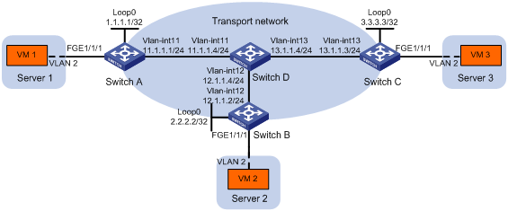
As shown in Figure 9:
· Configure VXLAN 10 as a unicast-mode VXLAN on Switch A, Switch B, and Switch C to provide Layer 2 connectivity for the VMs across the network sites.
· Manually establish VXLAN tunnels and assign the tunnels to VXLAN 10.
· Enable remote-MAC address learning.
Configuration procedure
1. Configure IP addresses and unicast routing settings:
# Assign IP addresses to interfaces, as shown in Figure 9. (Details not shown.)
# Configure OSPF on all transport network switches (Switches A through D). (Details not shown.)
2. Configure Switch A:
# Enable L2VPN.
<SwitchA> system-view
[SwitchA] l2vpn enable
# Create the VSI vpna and VXLAN 10.
[SwitchA] vsi vpna
[SwitchA-vsi-vpna] vxlan 10
[SwitchA-vsi-vpna-vxlan10] quit
[SwitchA-vsi-vpna] quit
# Assign an IP address to Loopback 0. The IP address will be used as the source IP address of the VXLAN tunnels to Switch B and Switch C.
[SwitchA] interface loopback0
[SwitchA-Loopback0] ip address 1.1.1.1 255.255.255.255
[SwitchA-Loopback0] quit
# Create a VXLAN tunnel to Switch B. The tunnel interface name is Tunnel 1.
[SwitchA] interface tunnel 1 mode vxlan
[SwitchA-Tunnel1] source 1.1.1.1
[SwitchA-Tunnel1] destination 2.2.2.2
[SwitchA-Tunnel1] quit
# Create a VXLAN tunnel to Switch C. The tunnel interface name is Tunnel 2.
[SwitchA] interface tunnel 2 mode vxlan
[SwitchA-Tunnel2] source 1.1.1.1
[SwitchA-Tunnel2] destination 3.3.3.3
[SwitchA-Tunnel2] quit
# Assign Tunnel 1 and Tunnel 2 to VXLAN 10.
[SwitchA] vsi vpna
[SwitchA-vsi-vpna] vxlan 10
[SwitchA-vsi-vpna-vxlan10] tunnel 1
[SwitchA-vsi-vpna-vxlan10] tunnel 2
[SwitchA-vsi-vpna-vxlan10] quit
[SwitchA-vsi-vpna] quit
# On FortyGigE 1/1/1, create Ethernet service instance 1000 to match frames from VLAN 2.
[SwitchA] interface fortygige 1/1/1
[SwitchA-FortyGigE1/1/1] service-instance 1000
[SwitchA-FortyGigE1/1/1-srv1000] encapsulation s-vid 2
# Map Ethernet service instance 1000 to the VSI vpna.
[SwitchA-FortyGigE1/1/1-srv1000] xconnect vsi vpna
[SwitchA-FortyGigE1/1/1-srv1000] quit
[SwitchA-FortyGigE1/1/1] quit
3. Configure Switch B:
# Enable L2VPN.
<SwitchB> system-view
[SwitchB] l2vpn enable
# Create the VSI vpna and VXLAN 10.
[SwitchB] vsi vpna
[SwitchB-vsi-vpna] vxlan 10
[SwitchB-vsi-vpna-vxlan10] quit
[SwitchB-vsi-vpna] quit
# Assign an IP address to Loopback 0. The IP address will be used as the source IP address of the VXLAN tunnels to Switch A and Switch C.
[SwitchB] interface loopback0
[SwitchB-Loopback0] ip address 2.2.2.2 255.255.255.255
[SwitchB-Loopback0] quit
# Create a VXLAN tunnel to Switch A. The tunnel interface name is Tunnel 2.
[SwitchB] interface tunnel 2 mode vxlan
[SwitchB-Tunnel2] source 2.2.2.2
[SwitchB-Tunnel2] destination 1.1.1.1
[SwitchB-Tunnel2] quit
# Create a VXLAN tunnel to Switch C. The tunnel interface name is Tunnel 3.
[SwitchB] interface tunnel 3 mode vxlan
[SwitchB-Tunnel3] source 2.2.2.2
[SwitchB-Tunnel3] destination 3.3.3.3
[SwitchB-Tunnel3] quit
# Assign Tunnel 2 and Tunnel 3 to VXLAN 10.
[SwitchB] vsi vpna
[SwitchB-vsi-vpna] vxlan 10
[SwitchB-vsi-vpna-vxlan10] tunnel 2
[SwitchB-vsi-vpna-vxlan10] tunnel 3
[SwitchB-vsi-vpna-vxlan10] quit
[SwitchB-vsi-vpna] quit
# On FortyGigE 1/1/1, create Ethernet service instance 1000 to match frames from VLAN 2.
[SwitchB] interface fortygige 1/1/1
[SwitchB-FortyGigE1/1/1] service-instance 1000
[SwitchB-FortyGigE1/1/1-srv1000] encapsulation s-vid 2
# Map Ethernet service instance 1000 to the VSI vpna.
[SwitchB-FortyGigE1/1/1-srv1000] xconnect vsi vpna
[SwitchB-FortyGigE1/1/1-srv1000] quit
[SwitchB-FortyGigE1/1/1] quit
4. Configure Switch C:
# Enable L2VPN.
<SwitchC> system-view
[SwitchC] l2vpn enable
# Create the VSI vpna and VXLAN 10.
[SwitchC] vsi vpna
[SwitchC-vsi-vpna] vxlan 10
[SwitchC-vsi-vpna-vxlan10] quit
[SwitchC-vsi-vpna] quit
# Assign an IP address to Loopback 0. The IP address will be used as the source IP address of the VXLAN tunnels to Switch A and Switch B.
[SwitchC] interface loopback0
[SwitchC-Loopback0] ip address 3.3.3.3 255.255.255.255
[SwitchC-Loopback0] quit
# Create a VXLAN tunnel to Switch A. The tunnel interface name is Tunnel 1.
[SwitchC] interface tunnel 1 mode vxlan
[SwitchC-Tunnel1] source 3.3.3.3
[SwitchC-Tunnel1] destination 1.1.1.1
[SwitchC-Tunnel1] quit
# Create a VXLAN tunnel to Switch B. The tunnel interface name is Tunnel 3.
[SwitchC] interface tunnel 3 mode vxlan
[SwitchC-Tunnel3] source 3.3.3.3
[SwitchC-Tunnel3] destination 2.2.2.2
[SwitchC-Tunnel3] quit
# Assign Tunnel 1 and Tunnel 3 to VXLAN 10.
[SwitchC] vsi vpna
[SwitchC-vsi-vpna] vxlan 10
[SwitchC-vsi-vpna-vxlan10] tunnel 1
[SwitchC-vsi-vpna-vxlan10] tunnel 3
[SwitchC-vsi-vpna-vxlan10] quit
[SwitchC-vsi-vpna] quit
# On FortyGigE 1/1/1, create Ethernet service instance 1000 to match frames from VLAN 2.
[SwitchC] interface fortygige 1/1/1
[SwitchC-FortyGigE1/1/1] service-instance 1000
[SwitchC-FortyGigE1/1/1-srv1000] encapsulation s-vid 2
# Map Ethernet service instance 1000 to the VSI vpna.
[SwitchC-FortyGigE1/1/1-srv1000] xconnect vsi vpna
[SwitchC-FortyGigE1/1/1-srv1000] quit
[SwitchC-FortyGigE1/1/1] quit
Verifying the configuration
1. Verify the VXLAN settings on the VTEPs. This example uses Switch A.
# Verify that the VXLAN tunnel interfaces on the VTEP are up.
[SwitchA] display interface tunnel 1
Tunnel1
Current state: UP
Line protocol state: UP
Description: Tunnel1 Interface
Bandwidth: 64 kbps
Maximum transmission unit: 1464
Internet protocol processing: Disabled
Last clearing of counters: Never
Tunnel source 1.1.1.1, destination 2.2.2.2
Tunnel protocol/transport UDP_VXLAN/IP
# Verify that the VXLAN tunnels have been assigned to the VXLAN.
[SwitchA] display l2vpn vsi verbose
VSI Name: vpna
VSI Index : 0
VSI State : Up
MTU : 1500
Bandwidth : -
Broadcast Restrain : -
Multicast Restrain : -
Unknown Unicast Restrain: -
MAC Learning : Enabled
MAC Table Limit : -
Drop Unknown : -
Flooding : Enabled
VXLAN ID : 10
Tunnels:
Tunnel Name Link ID State Type Flooding proxy
Tunnel1 0x5000001 Up Manual Disabled
Tunnel2 0x5000002 Up Manual Disabled
ACs:
AC Link ID State
FGE1/1/1 srv1000 0 Up
# Verify that the VTEP has learned the MAC addresses of remote VMs.
<SwitchA> display l2vpn mac-address
MAC Address State VSI Name Link ID/Name Aging
cc3e-5f9c-6cdb Dynamic vpna Tunnel1 Aging
cc3e-5f9c-23dc Dynamic vpna Tunnel2 Aging
--- 2 mac address(es) found ---
2. Verify that VM 1, VM 2, and VM 3 can ping each other. (Details not shown.)
Multicast-mode VXLAN configuration example
Network requirements
As shown in Figure 10:
· Configure VXLAN 10 as a multicast-mode VXLAN on Switch A, Switch B, and Switch C to provide Layer 2 connectivity for the VMs across the network sites.
· Manually establish VXLAN tunnels and assign the tunnels to VXLAN 10.
· Enable remote-MAC address learning.
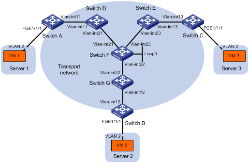
Table 1 IP address assignment
|
Device |
Interface |
IP address |
Device |
Interface |
IP address |
|
Switch A: |
|
|
Switch C: |
|
|
|
|
VLAN-interface 11 |
11.1.1.1/24 |
|
VLAN-interface 13 |
13.1.1.3/24 |
|
Switch D: |
|
|
Switch E: |
|
|
|
|
VLAN-interface 11 |
11.1.1.4/24 |
|
VLAN-interface 13 |
13.1.1.5/24 |
|
|
VLAN-interface 21 |
21.1.1.4/24 |
|
VLAN-interface 23 |
23.1.1.5/24 |
|
Switch F: |
|
|
Switch G: |
|
|
|
|
VLAN-interface 21 |
21.1.1.6/24 |
|
VLAN-interface 12 |
12.1.1.7/24 |
|
|
VLAN-interface 22 |
22.1.1.6/24 |
|
VLAN-interface 22 |
22.1.1.7/24 |
|
|
VLAN-interface 23 |
23.1.1.6/24 |
Switch B: |
|
|
|
|
Loop0 |
6.6.6.6/32 |
|
VLAN-interface 12 |
12.1.1.2/24 |
Configuration procedure
1. Configure IP addresses and unicast routing settings:
# Assign IP addresses to interfaces, as shown in Figure 10. (Details not shown.)
# Configure OSPF on all transport network switches (Switches A through G). (Details not shown.)
2. Configure Switch A:
# Enable L2VPN.
<SwitchA> system-view
[SwitchA] l2vpn enable
# Enable IP multicast routing.
[SwitchA] multicast routing
[SwitchA-mrib] quit
# Create the VSI vpna and VXLAN 10.
[SwitchA] vsi vpna
[SwitchA-vsi-vpna] vxlan 10
[SwitchA-vsi-vpna-vxlan10] quit
[SwitchA-vsi-vpna] quit
# Assign an IP address to VLAN-interface 11, and enable the IGMP host function on the interface. This interface's IP address will be the source IP address of VXLAN packets sent by the VTEP.
[SwitchA] interface vlan-interface 11
[SwitchA-Vlan-interface11] ip address 11.1.1.1 24
[SwitchA-Vlan-interface11] igmp host enable
[SwitchA-Vlan-interface11] quit
# Create a VXLAN tunnel to Switch B. The tunnel interface name is Tunnel 1.
[SwitchA] interface tunnel 1 mode vxlan
[SwitchA-Tunnel1] source 11.1.1.1
[SwitchA-Tunnel1] destination 12.1.1.2
[SwitchA-Tunnel1] quit
# Create a VXLAN tunnel to Switch C. The tunnel interface name is Tunnel 2.
[SwitchA] interface tunnel 2 mode vxlan
[SwitchA-Tunnel2] source 11.1.1.1
[SwitchA-Tunnel2] destination 13.1.1.3
[SwitchA-Tunnel2] quit
# Assign Tunnel 1 and Tunnel 2 to VXLAN 10.
[SwitchA] vsi vpna
[SwitchA-vsi-vpna] vxlan 10
[SwitchA-vsi-vpna-vxlan10] tunnel 1
[SwitchA-vsi-vpna-vxlan10] tunnel 2
# Configure the multicast group address and source IP address for multicast VXLAN packets.
[SwitchA-vsi-vpna-vxlan10] group 225.1.1.1 source 11.1.1.1
[SwitchA-vsi-vpna-vxlan10] quit
[SwitchA-vsi-vpna] quit
# On FortyGigE 1/1/1, create Ethernet service instance 1000 to match frames from VLAN 2.
[SwitchA] interface fortygige 1/1/1
[SwitchA-FortyGigE1/1/1] service-instance 1000
[SwitchA-FortyGigE1/1/1-srv1000] encapsulation s-vid 2
# Map Ethernet service instance 1000 to the VSI vpna.
[SwitchA-FortyGigE1/1/1-srv1000] xconnect vsi vpna
[SwitchA-FortyGigE1/1/1-srv1000] quit
[SwitchA-FortyGigE1/1/1] quit
3. Configure Switch B:
# Enable L2VPN.
<SwitchB> system-view
[SwitchB] l2vpn enable
# Enable IP multicast routing.
[SwitchB] multicast routing
[SwitchB-mrib] quit
# Create the VSI vpna and VXLAN 10.
[SwitchB] vsi vpna
[SwitchB-vsi-vpna] vxlan 10
[SwitchB-vsi-vpna-vxlan10] quit
[SwitchB-vsi-vpna] quit
# Assign an IP address to VLAN-interface 12, and enable the IGMP host function on the interface. This interface's IP address will be the source IP address of VXLAN packets sent by the VTEP.
[SwitchB] interface vlan-interface 12
[SwitchB-Vlan-interface12] ip address 12.1.1.2 24
[SwitchB-Vlan-interface12] igmp host enable
[SwitchB-Vlan-interface12] quit
# Create a VXLAN tunnel to Switch A. The tunnel interface name is Tunnel 2.
[SwitchB] interface tunnel 2 mode vxlan
[SwitchB-Tunnel2] source 12.1.1.2
[SwitchB-Tunnel2] destination 11.1.1.1
[SwitchB-Tunnel2] quit
# Create a VXLAN tunnel to Switch C. The tunnel interface name is Tunnel 3.
[SwitchB] interface tunnel 3 mode vxlan
[SwitchB-Tunnel3] source 12.1.1.2
[SwitchB-Tunnel3] destination 13.1.1.3
[SwitchB-Tunnel3] quit
# Assign Tunnel 2 and Tunnel 3 to VXLAN 10.
[SwitchB] vsi vpna
[SwitchB-vsi-vpna] vxlan 10
[SwitchB-vsi-vpna-vxlan10] tunnel 2
[SwitchB-vsi-vpna-vxlan10] tunnel 3
# Configure the VXLAN multicast group address and the source IP address for VXLAN packets.
[SwitchB-vsi-vpna-vxlan10] group 225.1.1.1 source 12.1.1.2
[SwitchB-vsi-vpna-vxlan10] quit
[SwitchB-vsi-vpna] quit
# On FortyGigE 1/1/1, create Ethernet service instance 1000 to match frames from VLAN 2.
[SwitchB] interface fortygige 1/1/1
[SwitchB-FortyGigE1/1/1] service-instance 1000
[SwitchB-FortyGigE1/1/1-srv1000] encapsulation s-vid 2
# Map Ethernet service instance 1000 to the VSI vpna.
[SwitchB-FortyGigE1/1/1-srv1000] xconnect vsi vpna
[SwitchB-FortyGigE1/1/1-srv1000] quit
[SwitchB-FortyGigE1/1/1] quit
4. Configure Switch C:
# Enable L2VPN.
<SwitchC> system-view
[SwitchC] l2vpn enable
# Enable IP multicast routing.
[SwitchC] multicast routing
[SwitchC-mrib] quit
# Create the VSI vpna and VXLAN 10.
[SwitchC] vsi vpna
[SwitchC-vsi-vpna] vxlan 10
[SwitchC-vsi-vpna-vxlan10] quit
[SwitchC-vsi-vpna] quit
# Assign an IP address to VLAN-interface 13, and enable the IGMP host function on the interface. This interface's IP address will be the source IP address of VXLAN packets sent by the VTEP.
[SwitchC] interface vlan-interface 13
[SwitchC-Vlan-interface13] ip address 13.1.1.3 24
[SwitchC-Vlan-interface13] igmp host enable
[SwitchC-Vlan-interface13] quit
# Create a VXLAN tunnel to Switch A. The tunnel interface name is Tunnel 1.
[SwitchC] interface tunnel 1 mode vxlan
[SwitchC-Tunnel1] source 13.1.1.3
[SwitchC-Tunnel1] destination 11.1.1.1
[SwitchC-Tunnel1] quit
# Create a VXLAN tunnel to Switch B. The tunnel interface name is Tunnel 3 .
[SwitchC] interface tunnel 3 mode vxlan
[SwitchC-Tunnel3] source 13.1.1.3
[SwitchC-Tunnel3] destination 12.1.1.2
[SwitchC-Tunnel3] quit
# Assign Tunnel 1 and Tunnel 3 to VXLAN 10.
[SwitchC] vsi vpna
[SwitchC-vsi-vpna] vxlan 10
[SwitchC-vsi-vpna-vxlan10] tunnel 1
[SwitchC-vsi-vpna-vxlan10] tunnel 3
# Configure the multicast group address and source IP address for VXLAN multicast packets.
[SwitchC-vsi-vpna-vxlan10] group 225.1.1.1 source 13.1.1.3
[SwitchC-vsi-vpna-vxlan10] quit
[SwitchC-vsi-vpna] quit
# On FortyGigE 1/1/1, create Ethernet service instance 1000 to match frames from VLAN 2.
[SwitchC] interface fortygige 1/1/1
[SwitchC-FortyGigE1/1/1] service-instance 1000
[SwitchC-FortyGigE1/1/1-srv1000] encapsulation s-vid 2
# Map Ethernet service instance 1000 to the VSI vpna.
[SwitchC-FortyGigE1/1/1-srv1000] xconnect vsi vpna
[SwitchC-FortyGigE1/1/1-srv1000] quit
[SwitchC-FortyGigE1/1/1] quit
5. Configure Switch D:
# Enable IP multicast routing.
<SwitchD> system-view
[SwitchD] multicast routing
[SwitchD-mrib] quit
# Enable IGMP on VLAN-interface 11.
[SwitchD] interface vlan-interface 11
[SwitchD-Vlan-interface11] igmp enable
[SwitchD-Vlan-interface11] quit
# Enable PIM-SM on VLAN-interface 21.
[SwitchD] interface vlan-interface 21
[SwitchD-Vlan-interface21] pim sm
[SwitchD-Vlan-interface21] quit
# Enable BIDIR-PIM.
[SwitchD] pim
[SwitchD-pim] bidir-pim enable
[SwitchD-pim] quit
6. Configure Switch E:
# Enable IP multicast routing.
<SwitchE> system-view
[SwitchE] multicast routing
[SwitchE-mrib] quit
# Enable IGMP on VLAN-interface 13.
[SwitchE] interface vlan-interface 13
[SwitchE-Vlan-interface13] igmp enable
[SwitchE-Vlan-interface13] quit
# Enable PIM-SM on VLAN-interface 23.
[SwitchE] interface vlan-interface 23
[SwitchE-Vlan-interface23] pim sm
[SwitchE-Vlan-interface23] quit
# Enable BIDIR-PIM.
[SwitchE] pim
[SwitchE-pim] bidir-pim enable
[SwitchE-pim] quit
7. Configure Switch F:
# Enable IP multicast routing.
<SwitchF> system-view
[SwitchF] multicast routing
[SwitchF-mrib] quit
# Enable PIM-SM on VLAN-interface 21, VLAN-interface 22, and VLAN-interface 23.
[SwitchF] interface vlan-interface 21
[SwitchF-Vlan-interface21] pim sm
[SwitchF-Vlan-interface21] quit
[SwitchF] interface vlan-interface 22
[SwitchF-Vlan-interface22] pim sm
[SwitchF-Vlan-interface22] quit
[SwitchF] interface vlan-interface 23
[SwitchF-Vlan-interface23] pim sm
[SwitchF-Vlan-interface23] quit
# Enable BIDIR-PIM.
[SwitchF] pim
[SwitchF-pim] bidir-pim enable
# Configure VLAN-interface 22 as a candidate-BSR, and configure Loopback 0 as a candidate-RP for BIDIR-PIM.
[SwitchF-pim] c-bsr 22.1.1.6
[SwitchF-pim] c-rp 6.6.6.6 bidir
[SwitchF-pim] quit
8. Configure Switch G:
# Enable IP multicast routing.
<SwitchG> system-view
[SwitchG] multicast routing
[SwitchG-mrib] quit
# Enable IGMP on VLAN-interface 12.
[SwitchG] interface vlan-interface 12
[SwitchG-Vlan-interface12] igmp enable
[SwitchG-Vlan-interface12] quit
# Enable PIM-SM on VLAN-interface 22.
[SwitchG] interface vlan-interface 22
[SwitchG-Vlan-interface22] pim sm
[SwitchG-Vlan-interface22] quit
# Enable BIDIR-PIM.
[SwitchG] pim
[SwitchG-pim] bidir-pim enable
[SwitchG-pim] quit
Verifying the configuration
1. Verify the VXLAN settings on the VTEPs. This example uses Switch A.
# Verify that the VXLAN tunnel interfaces on the VTEP are up.
[SwitchA] display interface tunnel 1
Tunnel1
Current state: UP
Line protocol state: UP
Description: Tunnel1 Interface
Bandwidth: 64 kbps
Maximum transmission unit: 1464
Internet protocol processing: Disabled
Last clearing of counters: Never
Tunnel source 11.1.1.1, destination 12.1.1.2
Tunnel protocol/transport UDP_VXLAN/IP
# Verify that the VXLAN tunnels have been assigned to the VXLAN.
[SwitchA] display l2vpn vsi verbose
VSI Name: vpna
VSI Index : 0
VSI State : Up
MTU : 1500
Bandwidth : -
Broadcast Restrain : -
Multicast Restrain : -
Unknown Unicast Restrain: -
MAC Learning : Enabled
MAC Table Limit : -
Drop Unknown : -
Flooding : Enabled
VXLAN ID : 10
Tunnels:
Tunnel Name Link ID State Type Flooding proxy
Tunnel1 0x5000001 Up Manual Disabled
Tunnel2 0x5000002 Up Manual Disabled
MTunnel0 0x6000000 Up Auto Disabled
ACs:
AC Link ID State
FGE1/1/1 srv1000 0 Up
# Verify that the VTEP has learned the MAC addresses of remote VMs.
<SwitchA> display l2vpn mac-address
MAC Address State VSI Name Link ID/Name Aging
cc3e-5f9c-6cdb Dynamic vpna Tunnel1 Aging
cc3e-5f9c-23dc Dynamic vpna Tunnel2 Aging
--- 2 mac address(es) found ---
# Verify that the VTEP has joined the VXLAN multicast group on VLAN-interface 11.
<SwitchA> display igmp host group
IGMP host groups in total: 1
Vlan-interface11(11.1.1.1):
IGMP host groups in total: 1
Group address Member state Expires
225.1.1.1 Idle Off
2. Verify that VM 1, VM 2, and VM 3 can ping each other. (Details not shown.)
Overview
Enhanced Neighbor Discovery Protocol (ENDP) dynamically discovers VTEPs and establish VXLAN tunnels.
Working mechanism
ENDP supports multiple VXLAN networks. ENDP uses network IDs to uniquely identify VXLANs. VTEPs can discover each other if they have the same network ID.
ENDP uses the client/server model.
· ENDS—The enhanced neighbor discovery server collects and maintains all neighbor information for a VXLAN network.
· ENDC—The enhanced neighbor discovery client works with the ENDS to learn neighbor information and sets up VXLAN tunnels to the neighbors.
Enable ENDS on one VTEP, and enable ENDC on all VTEPs. ENDP uses the following process to discover all VTEPs and establish VXLAN tunnels between the VTEPs:
1. The ENDCs register their IP addresses and other data with the ENDS.
2. The ENDS updates its ENDC database with received data, and then sends the updated database to each ENDC.
3. After receiving the register reply, the ENDCs establish a VXLAN tunnel with each other.
For high availability, you can configure a maximum of two ENDSs for a VXLAN network.
ENDP timers
ENDP uses an ENDS probe timer, an ENDC register timer, and a registration aging timer in neighbor discovery.
· ENDS probe timer—Sets the interval for an ENDC to detect an ENDS. This timer is maintained on ENDCs and is fixed at 5 seconds.
· ENDC register timer—Sets the interval for an ENDC to update its registration with an ENDS. This timer defaults to 15 seconds and can be changed by using the vxlan neighbor-discovery client register-interval command on ENDCs.
· Registration aging timer—This timer is five times the ENDC register timer. This timer is maintained on ENDSs. When the registration aging timer for an ENDC expires, the ENDS removes the ENDC from its ENDC database.
When an ENDC sends a register request to join a VXLAN network, a 5-second ENDS probe timer starts. The ENDC sends a register request to the ENDS every 5 seconds until it receives a response from the ENDS.
When the ENDC receives a response from the ENDS, the ENDS probe timer stops, and an ENDC register timer starts. The ENDC regularly sends register updates at the interval set by the register timer.
If the ENDC does not receive a response after sending five consecutive register packets, the ENDC clears its neighbor database and starts the ENDS probe timer.
The ENDC adds the register timer setting to each register packet. The ENDS records this timer setting when it adds the ENDC to the ENDC database. If no register update is received from the ENDC before five times the timer is reached, ENDS removes the ENDC.
ENDP authentication
ENDP authentication prevents malicious registration with an ENDS in an insecure network.
If authentication is disabled on an ENDS, all ENDCs, including authentication-enabled ENDCs, can register with the ENDS without authentication.
If authentication is enabled on an ENDS, only authentication-enabled ENDCs that use the same authentication key as the ENDS can register with the ENDS.
Configuring ENDP
ENDP runs on NVE tunnel interfaces. Before you configure ENDP on a VTEP, you must create an NVE tunnel interface.
For more information about tunneling configuration and commands, see Layer 3—IP Routing Configuration Guide and Layer 3—IP Routing Command Reference.
Configuring the VTEP as an ENDS
|
Step |
Command |
Remarks |
|
1. Enter system view. |
system-view |
N/A |
|
2. Create an NVE tunnel interface and enter tunnel interface view. |
interface tunnel tunnel-number mode nve |
By default, no tunnel interfaces exist. |
|
3. Assign a network ID to the tunnel interface. |
network-id network-id |
By default, no network ID is assigned to a tunnel interface. |
|
4. Configure a source IP address or source interface for the tunnel. |
source { ipv4-address | interface-type interface-number } |
By default, no source IP address or source interface is specified for a tunnel. This step specifies the IP address that the local ENDC registers with the ENDS. If a source interface is specified, its primary IP address is used. |
|
5. Enable ENDS on the tunnel interface. |
vxlan neighbor-discovery server enable |
By default, ENDS is disabled. When you enable ENDS on a tunnel interface, an ENDC is automatically enabled, with the source address of the NVE tunnel as the ENDS address. |
|
6. (Optional.) Enable ENDP authentication. |
vxlan neighbor-discovery authentication { cipher | simple } password |
By default, ENDP authentication is disabled. |
Configuring the VTEP as an ENDC
|
Step |
Command |
Remarks |
|
1. Enter system view. |
system-view |
N/A |
|
2. Create an NVE tunnel interface and enter tunnel interface view. |
interface tunnel tunnel-number mode nve |
By default, no tunnel interfaces exist on the device. |
|
3. Assign a network ID to the tunnel interface. |
network-id network-id |
By default, no network ID is assigned to a tunnel interface. |
|
4. Configure a source IP address or source interface for the tunnel. |
source { ipv4-address | interface-type interface-number } |
By default, no source IP address or source interface is specified for a tunnel. This step specifies the IP address that the local ENDC registers with the ENDS. If a source interface is specified, its primary IP address is used. |
|
5. Enable ENDC on the tunnel interface. |
vxlan neighbor-discovery client enable server-ip |
By default, ENDC is disabled. |
|
6. (Optional.) Enable ENDP authentication. |
vxlan neighbor-discovery authentication { cipher | simple } password |
By default, ENDP authentication is disabled. |
|
7. Configure the interval at which the ENDC updates its registration with the ENDS. |
vxlan neighbor-discovery client register-interval time-value |
By default, an ENDC updates its registration with an ENDS every 15 seconds. |
Displaying and maintaining ENDP
Execute display commands in any view and reset commands in user view.
|
Task |
Command |
|
Display neighbors that an ENDC has learned. |
display vxlan neighbor-discovery client member [ interface tunnel interface-number | local local-ip | remote client-ip | server server-ip ] |
|
Display ENDC statistics. |
display vxlan neighbor-discovery client statistics interface tunnel interface-number |
|
Display ENDC information. |
display vxlan neighbor-discovery client summary |
|
On an ENDS, display neighbors that have registered with the ENDS. |
display vxlan neighbor-discovery server member [ interface tunnel interface-number | local local-ip | remote client-ip ] |
|
On an ENDS, display ENDS statistics. |
display vxlan neighbor-discovery server statistics interface tunnel interface-number |
|
On an ENDS, display ENDS information. |
display vxlan neighbor-discovery server summary |
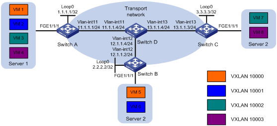
ENDP configuration example
Network requirements
As shown in Figure 11:
· Configure unicast-mode VXLANs on Switch A, Switch B, and Switch C to provide Layer 2 connectivity for the VMs across different sites.
· Configure ENDP to automatically set up VXLAN tunnels.
· Configure VXLAN IS-IS to advertise MAC reachability information and automate VXLAN tunnel assignment.
Table 2 shows the VLAN and VXLAN mapping scheme.
Table 2 VXLAN and VLAN mappings
|
VMs |
VTEPs |
VLAN |
VXLAN |
|
VM 1, VM 5 |
Switch A, Switch B |
VLAN 2 |
VXLAN 10000 |
|
VM 2, VM 6 |
Switch A, Switch B |
VLAN 3 |
VXLAN 10001 |
|
VM 3, VM 7 |
Switch A, Switch C |
VLAN 4 |
VXLAN 10002 |
|
VM 4, VM 8 |
Switch A, Switch C |
VLAN 5 |
VXLAN 10003 |
Configuration procedure
1. Configure IP addresses and routing settings:
# Assign IP addresses to interfaces, as shown in Figure 11.
# Configure OSPF on all transport network switches (Switches A through D). (Details not shown.)
2. Configure switch A:
# Enable L2VPN.
<SwitchA> system-view
[SwitchA] l2vpn enable
# Specify VXLAN 11111 as the reserved VXLAN for VXLAN IS-IS.
[SwitchA] reserved vxlan 11111
|
|
NOTE: The reserved VXLAN must be the same across VTEPs. |
# Create the VSI vpna and VXLAN 10000.
[SwitchA] vsi vpna
[SwitchA-vsi-vpna] vxlan 10000
[SwitchA-vsi-vpna-vxlan10000] quit
[SwitchA-vsi-vpna] quit
# Create the VSI vpnb and VXLAN 10001.
[SwitchA] vsi vpnb
[SwitchA-vsi-vpnb] vxlan 10001
[SwitchA-vsi-vpnb-vxlan10001] quit
[SwitchA-vsi-vpnb] quit
# Create the VSI vpnc and VXLAN 10002.
[SwitchA] vsi vpnc
[SwitchA-vsi-vpnc] vxlan 10002
[SwitchA-vsi-vpnc-vxlan10002] quit
[SwitchA-vsi-vpnc] quit
# Create the VSI vpnd and VXLAN 10003.
[SwitchA] vsi vpnd
[SwitchA-vsi-vpnd] vxlan 10003
[SwitchA-vsi-vpnd-vxlan10003] quit
[SwitchA-vsi-vpnd] quit
# Assign an IP address to Loopback 0. The IP address will be used as the source IP address of the VXLAN tunnels to Switch B and Switch C.
[SwitchA] interface loopback0
[SwitchA-Loopback0] ip address 1.1.1.1 255.255.255.255
[SwitchA-Loopback0] quit
# Configure the NVE tunnel interface Tunnel 0. ENDP will set up VXLAN tunnels by using settings on the NVE tunnel.
[SwitchA] interface tunnel 0 mode nve
[SwitchA-Tunnel0] source 1.1.1.1
[SwitchA-Tunnel0] network-id 1
# Enable ENDS on the NVE tunnel interface.
[SwitchA-Tunnel0] vxlan neighbor-discovery server enable
[SwitchA-Tunnel0] quit
# On FortyGigE 1/1/1, configure Ethernet service instance 1000 to match VLAN 2. Map the service instance to the VSI vpna.
[SwitchA] interface fortygige 1/1/1
[SwitchA-FortyGigE1/1/1] service-instance 1000
[SwitchA-FortyGigE1/1/1-srv1000] encapsulation s-vid 2
[SwitchA-FortyGigE1/1/1-srv1000] xconnect vsi vpna
[SwitchA-FortyGigE1/1/1-srv1000] quit
# On FortyGigE 1/1/1, configure Ethernet service instance 2000 to match VLAN 3. Map the service instance to the VSI vpnb.
[SwitchA-FortyGigE1/1/1] service-instance 2000
[SwitchA-FortyGigE1/1/1-srv2000] encapsulation s-vid 3
[SwitchA-FortyGigE1/1/1-srv2000] xconnect vsi vpnb
[SwitchA-FortyGigE1/1/1-srv2000] quit
# On FortyGigE 1/1/1, configure Ethernet service instance 3000 to match VLAN 4. Map the service instance to the VSI vpnc.
[SwitchA-FortyGigE1/1/1] service-instance 3000
[SwitchA-FortyGigE1/1/1-srv3000] encapsulation s-vid 4
[SwitchA-FortyGigE1/1/1-srv3000] xconnect vsi vpnc
[SwitchA-FortyGigE1/1/1-srv3000] quit
# On FortyGigE 1/1/1, configure Ethernet service instance 4000 to match VLAN 5. Map the service instance to the VSI vpnd.
[SwitchA-FortyGigE1/1/1] service-instance 4000
[SwitchA-FortyGigE1/1/1-srv4000] encapsulation s-vid 5
[SwitchA-FortyGigE1/1/1-srv4000] xconnect vsi vpnd
[SwitchA-FortyGigE1/1/1-srv4000] quit
[SwitchA-FortyGigE1/1/1] quit
# Start the VXLAN IS-IS process. Enable VXLAN autonegotiation and MAC advertisement.
[SwitchA] vxlan-isis
[SwitchA-vxlan-isis] negotiate-vni enable
[SwitchA-vxlan-isis] mac-synchronization enable
[SwitchA-vxlan-isis] quit
3. Configure Switch B:
# Enable L2VPN.
<SwitchB> system-view
[SwitchB] l2vpn enable
# Specify VXLAN 11111 as the reserved VXLAN for VXLAN IS-IS.
[SwitchB] reserved vxlan 11111
# Create the VSI vpna and VXLAN 10000.
[SwitchB] vsi vpna
[SwitchB-vsi-vpna] vxlan 10000
[SwitchB-vsi-vpna-vxlan10000] quit
[SwitchB-vsi-vpna] quit
# Create the VSI vpnb and VXLAN 10001.
[SwitchB] vsi vpnb
[SwitchB-vsi-vpnb] vxlan 10001
[SwitchB-vsi-vpnb-vxlan10001] quit
[SwitchB-vsi-vpna] quit
# Assign an IP address to Loopback 0. The IP address will be used as the source IP address of the VXLAN tunnels to Switch A and Switch C.
[SwitchB] interface loopback0
[SwitchB-Loopback0] ip address 2.2.2.2 255.255.255.255
[SwitchB-Loopback0] quit
# Configure the NVE tunnel interface Tunnel 0. Specify the tunnel interface as an ENDC of the ENDS at 1.1.1.1. ENDP will set up VXLAN tunnels by using settings on the NVE tunnel.
[SwitchB] interface tunnel 0 mode nve
[SwitchB-Tunnel0] source 2.2.2.2
[SwitchB-Tunnel0] network-id 1
[SwitchB-Tunnel0] vxlan neighbor-discovery client enable 1.1.1.1
[SwitchB-Tunnel0] quit
# On FortyGigE 1/1/1, configure Ethernet service instance 1000 to match VLAN 2. Map the service instance to the VSI vpna.
[SwitchB] interface fortygige 1/1/1
[SwitchB-FortyGigE1/1/1] service-instance 1000
[SwitchB-FortyGigE1/1/1-srv1000] encapsulation s-vid 2
[SwitchB-FortyGigE1/1/1-srv1000] xconnect vsi vpna
[SwitchB-FortyGigE1/1/1-srv1000] quit
# On FortyGigE 1/1/1, configure Ethernet service instance 2000 to match VLAN 3. Map the service instance to the VSI vpnb.
[SwitchB-FortyGigE1/1/1] service-instance 2000
[SwitchB-FortyGigE1/1/1-srv2000] encapsulation s-vid 3
[SwitchB-FortyGigE1/1/1-srv2000] xconnect vsi vpnb
[SwitchB-FortyGigE1/1/1-srv2000] quit
[SwitchB-FortyGigE1/1/1] quit
# Start the VXLAN IS-IS process. Enable VXLAN autonegotiation and MAC advertisement.
[SwitchB] vxlan-isis
[SwitchB-vxlan-isis] negotiate-vni enable
[SwitchB-vxlan-isis] mac-synchronization enable
[SwitchB-vxlan-isis] quit
4. Configure Switch C:
# Enable L2VPN.
<SwitchC> system-view
[SwitchC] l2vpn enable
# Specify VXLAN 11111 as the reserved VXLAN for VXLAN IS-IS.
[SwitchC] reserved vxlan 11111
# Create the VSI vpna and VXLAN 10002.
[SwitchC] vsi vpna
[SwitchC-vsi-vpna] vxlan 10002
[SwitchC-vsi-vpna-vxlan10002] quit
[SwitchC-vsi-vpna] quit
# Create the VSI vpnb and VXLAN 10003.
[SwitchC] vsi vpnb
[SwitchC-vsi-vpnb] vxlan 10003
[SwitchC-vsi-vpnb-vxlan10003] quit
[SwitchC-vsi-vpnb] quit
# Assign an IP address to Loopback 0. The IP address will be used as the source IP address of the VXLAN tunnels to Switch A and Switch B.
[SwitchC] interface loopback0
[SwitchC-Loopback0] ip address 3.3.3.3 255.255.255.255
[SwitchC-Loopback0] quit
# Configure the NVE tunnel interface Tunnel 0. Specify the tunnel interface as an ENDC of the ENDS at 1.1.1.1. ENDP will set up VXLAN tunnels by using settings on the NVE tunnel.
[SwitchC] interface tunnel 0 mode nve
[SwitchC-Tunnel0] source 3.3.3.3
[SwitchC-Tunnel0] network-id 1
[SwitchC-Tunnel0] vxlan neighbor-discovery client enable 1.1.1.1
[SwitchC-Tunnel0] quit
# On FortyGigE 1/1/1, configure Ethernet service instance 1000 to match VLAN 4. Map the service instance to the VSI vpna.
[SwitchC] interface fortygige 1/1/1
[SwitchC-FortyGigE1/1/1] service-instance 1000
[SwitchC-FortyGigE1/1/1-srv1000] encapsulation s-vid 4
[SwitchC-FortyGigE1/1/1-srv1000] xconnect vsi vpna
[SwitchC-FortyGigE1/1/1-srv1000] quit
# On FortyGigE 1/1/1, configure Ethernet service instance 2000 to match VLAN 5. Map the service instance to the VSI vpnb.
[SwitchC-FortyGigE1/1/1] service-instance 2000
[SwitchC-FortyGigE1/1/1-srv2000] encapsulation s-vid 5
[SwitchC-FortyGigE1/1/1-srv2000] xconnect vsi vpnb
[SwitchC-FortyGigE1/1/1-srv2000] quit
[SwitchC-FortyGigE1/1/1] quit
# Start the VXLAN IS-IS process. Enable VXLAN autonegotiation and MAC advertisement.
[SwitchC] vxlan-isis
[SwitchC-vxlan-isis] negotiate-vni enable
[SwitchC-vxlan-isis] mac-synchronization enable
[SwitchC-vxlan-isis] quit
Verifying the configuration
1. Verify the configuration on VTEPs (for example, Switch A):
# Verity that the VTEP has learned all neighbors in the VXLAN network.
[SwitchA] display vxlan neighbor-discovery server summary
Interface Local Address Network ID Auth Members
Tunnel0 1.1.1.1 1 enabled 3
[SwitchA] display vxlan neighbor-discovery server member
Interface: Tunnel0 Network ID: 1
IP Address: 1.1.1.1
Client Address System ID Expire Created Time
1.1.1.1 000F-0001-0001 25 2011/01/01 00:00:30
2.2.2.2 000F-0001-0002 25 2011/01/01 00:00:43
3.3.3.3 000F-0001-0003 24 2011/01/01 01:00:46
# Verify that all neighbors are up.
[SwitchA] display vxlan neighbor-discovery client member
Interface: Tunnel0 Network ID: 1
Local Address: 1.1.1.1
Server Address: 1.1.1.1
Neighbor System ID Created Time Expire Status
2.2.2.2 000F-0001-0002 2014/01/01 12:12:12 13 Up
3.3.3.3 000F-0001-0003 2014/01/01 12:12:12 12 Up
# Verify that all VXLAN tunnel interfaces are up.
[SwitchA] display interface tunnel
Tunnel 1
Current state: UP
Line protocol state: UP
Description: Tunnel1 Interface
Bandwidth: 64 kbps
Maximum transmission unit: 1464
Internet protocol processing: Disabled
Last clearing of counters: Never
Tunnel source 1.1.1.1, destination 2.2.2.2
Tunnel protocol/transport UDP_VXLAN/IP
Tunnel 2
Current state: UP
Line protocol state: UP
Description: Tunnel2 Interface
Bandwidth: 64 kbps
Maximum transmission unit: 1464
Internet protocol processing: Disabled
Last clearing of counters: Never
Tunnel source 1.1.1.1, destination 3.3.3.3
Tunnel protocol/transport UDP_VXLAN/IP
# Verify that VXLAN tunnels have been assigned to the correct VXLANs.
[SwitchA] display l2vpn vsi verbose
VSI Name: vpna
VSI Index : 0
VSI State : Up
MTU : 1500
Bandwidth : -
Broadcast Restrain : -
Multicast Restrain : -
Unknown Unicast Restrain: -
MAC Learning : Enabled
MAC Table Limit : -
Drop Unknown : -
Flooding : Enabled
VXLAN ID : 10000
Tunnels:
Tunnel Name Link ID State Type Flooding proxy
Tunnel1 0x5000001 UP Auto Disabled
ACs:
AC Link ID State
FGE1/1/1 srv1000 0 Up
VSI Name: vpnb
VSI Index : 1
VSI State : Up
MTU : 1500
Bandwidth : -
Broadcast Restrain : -
Multicast Restrain : -
Unknown Unicast Restrain: -
MAC Learning : Enabled
MAC Table Limit : -
Drop Unknown : -
Flooding : Enabled
VXLAN ID : 10001
Tunnels:
Tunnel Name Link ID State Type Flooding proxy
Tunnel1 0x5000001 UP Auto Disabled
ACs:
AC Link ID State
FGE1/1/1 srv2000 0 Up
VSI Name: vpnc
VSI Index : 2
VSI State : Up
MTU : 1500
Bandwidth : -
Broadcast Restrain : -
Multicast Restrain : -
Unknown Unicast Restrain: -
MAC Learning : Enabled
MAC Table Limit : -
Drop Unknown : -
Flooding : Enabled
VXLAN ID : 10002
Tunnels:
Tunnel Name Link ID State Type Flooding proxy
Tunnel2 0x5000002 UP Auto Disabled
ACs:
AC Link ID State
FGE1/1/1 srv3000 0 Up
VSI Name: vpnd
VSI Index : 3
VSI State : Up
MTU : 1500
Bandwidth : -
Broadcast Restrain : -
Multicast Restrain : -
Unknown Unicast Restrain: -
MAC Learning : Enabled
MAC Table Limit : -
Drop Unknown : -
Flooding : Enabled
VXLAN ID : 10003
Tunnels:
Tunnel Name Link ID State Type Flooding proxy
Tunnel2 0x5000002 UP Auto Disabled
ACs:
AC Link ID State
FGE1/1/1 srv4000 0 Up
# Verify that the VTEP has learned the MAC addresses of remote VMs to the VSIs.
[SwitchA] display l2vpn mac-address
MAC Address State VSI Name Link ID/Name Aging
cc3e-5f9c-6cdb IS-IS vpna Tunnel1 Aging
cc3e-5f9c-23dc IS-IS vpnc Tunnel2 Aging
--- 1 mac address(es) found ---
# Verify that the VTEP has established adjacencies with all its neighbors.
[SwitchA] display vxlan isis peer
System ID: 4431.9234.2602
Link interface: Tunnel1
Circuit ID: 4431.9234.2602.0001
State: Up
Hold time: 8s
Neighbour DED priority: 64
Uptime: 47:48:34
System ID: 4431.9234.1f68
Link interface: Tunnel2
Circuit ID: 4431.9234.1f68.0000
State: Up
Hold time: 27s
Neighbour DED priority: 64
Uptime: 47:50:30
# Verify that the VXLAN IS-IS LSDB is populated correctly.
[SwitchA] display vxlan isis lsdb
Link state database information for VXLAN ISIS (Tunnel 1)
LSP ID Seq num Checksum Holdtime Length Overload
-----------------------------------------------------------------------------
4431.9234.1f68.0000-00 0x000000c2 0xdc02 656 59 0
4431.9234.2602.0000-00* 0x000000c3 0xd136 326 70 0
4431.9234.2602.0001-00* 0x000000c1 0x73ca 658 57 0
Link state database information for VXLAN ISIS (Tunnel 2)
LSP ID Seq num Checksum Holdtime Length Overload
-----------------------------------------------------------------------------
4431.9234.1f68.0000-00 0x000000c2 0xdc02 656 59 0
4431.9234.2613.0000-00* 0x000000c3 0xd136 326 70 0
4431.9234.2613.0002-00* 0x000000c1 0x73ca 658 57 0
Flags: *-Self LSP, +-Self LSP(Extended)
# Verify that VXLAN IS-IS has learned the MAC addresses of remote VMs.
[SwitchA] display vxlan isis remote-mac
MAC Flags: D-MAC conflict with local dynamic MAC.
F-MAC has been issued to the remote MAC address table.
S-MAC conflict with local static or selective-flooding MAC.
A-Tunnel interface can forward traffic to the MAC.
VXLAN ID: 10000
MAC address: cc3e-5f9c-6cdb
Interface: Tunnel1
Flags: AF
VXLAN ID: 10002
MAC address: cc3e-5f9c-23dc
Interface: Tunnel2
Flags: AF
# Verify that VXLAN IS-IS has learned remote VXLAN information.
[SwitchA] display vxlan isis remote-vxlan
VXLAN Flags: S-VXLAN supported at the local end
F-Association between VXLAN and Tunnels has been flushed to L2VPN
VXLAN ID: 10000
Flags: FS
Tunnel: 1
VXLAN ID: 10001
Flags: FS
Tunnel: 1
VXLAN ID: 10002
Flags: FS
Tunnel: 2
VXLAN ID: 10003
Flags: FS
Tunnel: 2
2. Verify that VMs in different sites can ping each other if they are in the same VLAN. VMs cannot ping each other if they are not in the same VLAN. (Details not shown.)
Use VXLAN IS-IS to automate VXLAN tunnel assignment and MAC reachability information synchronization between VTEPs.
VXLAN IS-IS configuration task list
|
Tasks at a glance |
|
(Required.) Specifying a reserved VXLAN for VXLAN IS-IS |
|
(Required.) Enabling VXLAN autonegotiation to automate VXLAN tunnel assignment |
|
(Required.) Enabling MAC advertisement through VXLAN IS-IS |
|
(Optional.) Tuning VXLAN IS-IS parameters |
Specifying a reserved VXLAN for VXLAN IS-IS
For the VTEP to exchange VXLAN IS-IS packets with remote VTEPs, you must specify a reserved VXLAN. The reserved VXLAN must be the same across the VTEPs.
You can specify only one reserved VXLAN on the VTEP. All VSIs on the VTEP use the reserved VXLAN to transmit and receive VXLAN IS-IS packets. The reserved VXLAN cannot be a VXLAN created on any VSI.
To specify a reserved VXLAN for VXLAN IS-IS:
|
Step |
Command |
Remarks |
|
1. Enter system view. |
system-view |
N/A |
|
2. Specify a VXLAN as the reserved VXLAN. |
reserved vxlan vxlan-id |
By default, no VXLAN is specified as the reserved VXLAN. |
Enabling VXLAN autonegotiation to automate VXLAN tunnel assignment
VXLAN autonegotiation enables the VTEPs to advertise local VXLAN IDs through VXLAN IS-IS. Two VTEPs automatically assign the VXLAN tunnel between them to a VXLAN if both of them have the VXLAN ID.
To automate VXLAN tunnel assignment:
|
Step |
Command |
Remarks |
|
1. Enter system view. |
system-view |
N/A |
|
2. Enter VXLAN IS-IS view. |
vxlan-isis |
By default, the VXLAN IS-IS process is not created. The VTEP creates the VXLAN IS-IS process if it has not been created. |
|
3. Enable VXLAN autonegotiation. |
negotiate-vni enable |
By default, VXLAN IS-IS does not exchange VXLAN IDs. |
Enabling MAC advertisement through VXLAN IS-IS
To advertise and receive MAC reachability information through VXLAN IS-IS:
|
Step |
Command |
Remarks |
|
1. Enter system view. |
system-view |
N/A |
|
2. Enter VXLAN IS-IS view. |
vxlan-isis |
By default, the VXLAN IS-IS process is not created. |
|
3. Enable MAC advertisement through VXLAN IS-IS. |
mac-synchronization enable |
By default, VXLAN IS-IS does not advertise or receive MAC reachability information. |
Tuning VXLAN IS-IS parameters
Tune VXLAN IS-IS parameters on a VXLAN or NVE tunnel interface to optimize the protocol performance.
On an NVE tunnel interface, the VXLAN IS-IS parameter changes apply to all VXLAN tunnels that are set up using the NVE tunnel interface.
Setting the VXLAN IS-IS hello interval and the hello multiplier for calculating the adjacency hold time
VTEPs send VXLAN IS-IS hellos over VXLAN tunnels to establish and maintain adjacencies and elect a DED on each tunnel. A short interval increases the speed of network convergence but requires more system resources.
Adjacency hold time sets the amount of time that the remote VTEPs can retain the adjacency with the local VTEP before an adjacency update.
· If Graceful Restart is disabled, the adjacency hold time equals the VXLAN IS-IS hello interval multiplied by the hello multiplier.
· If Graceful Restart is enabled, the adjacency hold time equals the restart interval or equals the VXLAN IS-IS hello interval multiplied by the hello multiplier, whichever is greater.
VTEPs send their adjacency hold time in hello packets to update the adjacencies with their neighbors. A VTEP removes the adjacency with a neighbor if it does not receive a hello packet from the neighbor before the timer expires.
To set the VXLAN IS-IS hello interval and the hello multiplier on a VXLAN or NVE tunnel interface:
|
Step |
Command |
Remarks |
|
1. Enter system view. |
system-view |
N/A |
|
2. Enter VXLAN or NVE tunnel interface view. |
interface tunnel tunnel-number [ mode { nve | vxlan } ] |
N/A |
|
3. Set the VXLAN IS-IS hello interval. |
overlay isis timer hello seconds |
The default hello interval is 10 seconds. The hello interval of a DED is one-third of the configured hello interval. |
|
4. Set the hello multiplier for calculating the adjacency hold time. |
overlay isis timer holding-multiplier value |
The default multiplier is 3. The maximum adjacency hold time is 65535 seconds. If this value is exceeded, the actual adjacency hold time is set to 65535 seconds. |
Configuring the DED priority and CSNP interval
On each VXLAN tunnel, the VTEP with higher DED priority is elected the DED to send CSNP packets periodically for LSDB synchronization. If the VTEPs have the same DED priority, the one with the higher MAC address is elected.
To set the DED priority and CSNP interval:
|
Step |
Command |
Remarks |
|
1. Enter system view. |
system-view |
N/A |
|
2. Enter VXLAN or NVE tunnel interface view. |
interface tunnel tunnel-number [ mode { nve | vxlan } ] |
N/A |
|
3. Set the DED priority of the VTEP on the VXLAN tunnel interface. |
overlay isis ded-priority value |
The default DED priority is 64. |
|
4. Set the CSNP interval. |
overlay isis timer csnp seconds |
The default CSNP interval is 10 seconds. The setting takes effect if the VTEP is elected the DED on the VXLAN tunnel. |
Tuning LSP timers
Change LSP timer settings depending on network stability to increase the network convergence speed and protect CPU from unnecessary route recalculations.
Table 3 VXLAN IS-IS LSP timers
|
LSP timer |
Functionality |
Tuning guidelines |
|
Minimum LSP transmit interval |
Sets the minimum interval for transmitting LSPs out of an interface. You can also set the number of LSPs that can be sent at each interval. |
Increase the interval to reduce LSP traffic in the network. Decrease the interval for quick LSDB synchronization. |
|
LSP lifetime |
Sets the amount of time that an LSP can be retained in an LSDB. |
Set the lifetime to a higher value than the LSP refresh interval. |
|
LSP refresh interval |
Controls the update interval for an LSP. |
Increase the interval to protect the CPU from frequent LSP generation. Decrease the interval for quick reaction to topology change events. |
Setting the minimum LSP transmit interval and the maximum number of LSPs sent at each interval
When LSDB changes, VXLAN IS-IS sends LSP updates to notify its neighbors.
To control VXLAN IS-IS LSP traffic on the network:
|
Step |
Command |
Remarks |
|
1. Enter system view. |
system-view |
N/A |
|
2. Enter VXLAN or NVE tunnel interface view. |
interface tunnel tunnel-number [ mode { nve | vxlan } ] |
N/A |
|
3. Set the minimum LSP transmit interval and the maximum number of LSP segments sent at each interval. |
overlay isis timer lsp time [ count count ] |
By default, the minimum LSP transmit interval is 100 milliseconds. A maximum of five LSP segments can be sent at each interval. |
Setting the maximum LSP lifetime
VTEPs add a lifetime in each LSP they advertise. A VTEP removes an LSP from the LSDB if it does not receive an update for the LSP before the lifetime expires.
To set the maximum lifetime of the LSPs generated by the VTEP:
|
Step |
Command |
Remarks |
|
1. Enter system view. |
system-view |
N/A |
|
2. Enter VXLAN IS-IS view. |
vxlan-isis |
N/A |
|
3. Set the maximum LSP lifetime. |
timer lsp-max-age seconds |
The default maximum LSP lifetime is 1200 seconds. |
Setting the LSP refresh interval
The VTEP sends LSP updates at the refresh interval to update MAC reachability information.
To set the LSP refresh interval:
|
Step |
Command |
Remarks |
|
1. Enter system view. |
system-view |
N/A |
|
2. Enter VXLAN IS-IS view. |
vxlan-isis |
N/A |
|
3. Set the LSP refresh interval. |
timer lsp-refresh seconds |
The default refresh interval is 900 seconds. To avoid unnecessary age-outs, set the LSP refresh interval to a lower value than the LSP lifetime. |
Enabling adjacency change logging
Adjacency change logging enables the VXLAN IS-IS process to send a log message to the information center when an adjacency change occurs. With the information center, you can set log message filtering and output rules, including output destinations. For more information about using the information center, see Network Management and Monitoring Configuration Guide.
To enable adjacency change logging:
|
Step |
Command |
Remarks |
|
1. Enter system view. |
system-view |
N/A |
|
2. Enter VXLAN IS-IS view. |
vxlan-isis |
N/A |
|
3. Enable VXLAN IS-IS adjacency change logging. |
log-peer-change enable |
By default, VXLAN IS-IS adjacency change logging is enabled. |
Configuring Graceful Restart for VXLAN IS-IS
Graceful Restart guarantees nonstop forwarding while the peer VXLAN IS-IS process are re-establishing their adjacency after a process restart or active/standby switchover occurs.
For the Graceful Restart feature to work, you must enable it on the peer VTEPs.
If Graceful Restart is enabled, the adjacency hold time equals the restart interval or equals the VXLAN IS-IS hello interval multiplied by the hello multiplier, whichever is greater. (For a DED, the hello interval is one-third of the hello interval set using the overlay isis timer hello command.)
To configure Graceful Restart for VXLAN IS-IS:
|
Step |
Command |
Remarks |
|
1. Enter system view. |
system-view |
N/A |
|
2. Enter VXLAN IS-IS view. |
vxlan-isis |
N/A |
|
3. Enable Graceful Restart for VXLAN IS-IS. |
graceful-restart |
By default, VXLAN IS-IS Graceful Restart is disabled. |
|
4. Set the GR restart interval. |
graceful-restart interval interval-value |
The default restart interval is 300 seconds. A GR process fails if the VXLAN IS-IS process fails to complete LSDB synchronization before the restart interval expires. When the GR fails, the peer VTEP removes the VXLAN IS-IS adjacency with the local VTEP. |
Increasing the maximum number of MAC entries in an LSP
The VXLAN IS-IS process advertises all local MAC reachability information in one LSP. By default, an LSP can convey a maximum of 55 x 210 MAC address entries.
To increase this number to include all local MAC address entries, create virtual systems. Each virtual system represents an increase of 55 x 210 MAC address entries. If n virtual systems are created, the maximum number of MAC address entries in an LSP is (n+1) x 55 x 210.
To increase the maximum number of MAC entries in an LSP:
|
Step |
Command |
Remarks |
|
1. Enter system view. |
system-view |
N/A |
|
2. Enter VXLAN IS-IS view. |
vxlan-isis |
N/A |
|
3. Create a VXLAN IS-IS virtual system. |
virtual-system system-id |
By default, no VXLAN IS-IS virtual systems are created.
The virtual system ID must be unique in the network. |
Displaying and maintaining VXLAN IS-IS
Execute display commands in any view and reset commands in user view.
|
Task |
Command |
|
Display brief information about the VXLAN IS-IS process. |
display vxlan isis brief |
|
Display VXLAN IS-IS GR state. |
display vxlan isis graceful-restart status |
|
Display local MAC reachability information maintained by VXLAN IS-IS. |
display vxlan isis local-mac dynamic [ [ vxlan vxlan-id ] [ count ] ] |
|
Display VXLAN IS-IS LSDB information. |
display vxlan isis lsdb [ local | lsp-id lsp-id | verbose ] * [ tunnel tunnel-number ] |
|
Display VXLAN IS-IS neighbors. |
display vxlan isis peer |
|
Display remote MAC reachability information maintained by VXLAN IS-IS. |
display vxlan isis remote-mac [ [ vxlan vxlan-id ] [ count ] ] |
|
Display remote VXLAN information learned through VXLAN IS-IS. |
display vxlan isis remote-vxlan [ vxlan-id | count ] |
|
Display VXLAN IS-IS information for tunnel interfaces. |
display vxlan isis tunnel [ tunnel-number ] |
|
Clear data for the VXLAN IS-IS process. |
reset vxlan isis |
VXLAN IS-IS configuration example
Network requirements
As shown in Figure 12:
· Configure unicast-mode VXLANs on Switch A, Switch B, and Switch C to provide Layer 2 connectivity for the VMs across different sites.
· Manually set up VXLAN tunnels between the VTEPs.
· Configure VXLAN IS-IS to advertise MAC reachability information and automate VXLAN tunnel assignment.
Table 4 shows the VLAN and VXLAN mapping scheme.
Table 4 VXLAN and VLAN mappings
|
VMs |
VTEPs |
VLAN |
VXLAN |
|
VM 1, VM 5 |
Switch A, Switch B |
VLAN 2 |
VXLAN 10000 |
|
VM 2, VM 6 |
Switch A, Switch B |
VLAN 3 |
VXLAN 10001 |
|
VM 3, VM 7 |
Switch A, Switch C |
VLAN 4 |
VXLAN 10002 |
|
VM 4, VM 8 |
Switch A, Switch C |
VLAN 5 |
VXLAN 10003 |

Configuration procedure
1. Configure IP addresses and routing settings:
# Assign IP addresses to interfaces, as shown in Figure 12. (Details not shown.)
# Configure OSPF on all transport network switches (Switches A through D). (Details not shown.)
2. Configure Switch A:
# Enable L2VPN.
<SwitchA> system-view
[SwitchA] l2vpn enable
# Specify VXLAN 11111 as the reserved VXLAN for VXLAN IS-IS.
[SwitchA] reserved vxlan 11111
|
|
NOTE: The reserved VXLAN must be the same across VTEPs. |
# Create the VSI vpna and VXLAN 10000.
[SwitchA] vsi vpna
[SwitchA-vsi-vpna] vxlan 10000
[SwitchA-vsi-vpna-vxlan10000] quit
[SwitchA-vsi-vpna] quit
# Create the VSI vpnb and VXLAN 10001.
[SwitchA] vsi vpnb
[SwitchA-vsi-vpnb] vxlan 10001
[SwitchA-vsi-vpnb-vxlan10001] quit
[SwitchA-vsi-vpnb] quit
# Create the VSI vpnc and VXLAN 10002.
[SwitchA] vsi vpnc
[SwitchA-vsi-vpnc] vxlan 10002
[SwitchA-vsi-vpnc-vxlan10002] quit
[SwitchA-vsi-vpnc] quit
# Create the VSI vpnd and VXLAN 10003.
[SwitchA] vsi vpnd
[SwitchA-vsi-vpnd] vxlan 10003
[SwitchA-vsi-vpnd-vxlan10003] quit
[SwitchA-vsi-vpnd] quit
# Assign an IP address to Loopback 0. The IP address will be used as the source IP address of the VXLAN tunnels to Switch B and Switch C.
[SwitchA] interface loopback0
[SwitchA-Loopback0] ip address 1.1.1.1 255.255.255.255
[SwitchA-Loopback0] quit
# Create a VXLAN tunnel to Switch B. The tunnel interface is Tunnel 1. The tunnel destination is Loopback 0 at 2.2.2.2 on Switch B.
[SwitchA] interface tunnel 1 mode vxlan
[SwitchA-Tunnel1] source 1.1.1.1
[SwitchA-Tunnel1] destination 2.2.2.2
[SwitchA-Tunnel1] quit
# Create a VXLAN tunnel to Switch C. The tunnel interface is Tunnel 2. The tunnel destination is Loopback 0 at 3.3.3.3 on Switch C.
[SwitchA] interface tunnel 2 mode vxlan
[SwitchA-Tunnel2] source 1.1.1.1
[SwitchA-Tunnel2] destination 3.3.3.3
[SwitchA-Tunnel2] quit
# On FortyGigE 1/1/1, configure Ethernet service instance 1000 to match VLAN 2. Map the service instance to the VSI vpna.
[SwitchA] interface fortygige 1/1/1
[SwitchA-FortyGigE1/1/1] service-instance 1000
[SwitchA-FortyGigE1/1/1-srv1000] encapsulation s-vid 2
[SwitchA-FortyGigE1/1/1-srv1000] xconnect vsi vpna
[SwitchA-FortyGigE1/1/1-srv1000] quit
# On FortyGigE 1/1/1, create Ethernet service instance 2000 to match VLAN 3. Map the service instance to the VSI vpnb.
[SwitchA-FortyGigE1/1/1] service-instance 2000
[SwitchA-FortyGigE1/1/1-srv2000] encapsulation s-vid 3
[SwitchA-FortyGigE1/1/1-srv2000] xconnect vsi vpnb
[SwitchA-FortyGigE1/1/1-srv2000] quit
# On FortyGigE 1/1/1, configure Ethernet service instance 3000 to match VLAN 4. Map the service instance to the VSI vpnc.
[SwitchA-FortyGigE1/1/1] service-instance 3000
[SwitchA-FortyGigE1/1/1-srv3000] encapsulation s-vid 4
[SwitchA-FortyGigE1/1/1-srv3000] xconnect vsi vpnc
[SwitchA-FortyGigE1/1/1-srv3000] quit
# On FortyGigE 1/1/1, configure Ethernet service instance 4000 to match VLAN 5. Map the service instance 4000 to the VSI vpnd.
[SwitchA-FortyGigE1/1/1] service-instance 4000
[SwitchA-FortyGigE1/1/1-srv4000] encapsulation s-vid 5
[SwitchA-FortyGigE1/1/1-srv4000] xconnect vsi vpnd
[SwitchA-FortyGigE1/1/1-srv4000] quit
[SwitchA-FortyGigE1/1/1] quit
# Start the VXLAN IS-IS process. Enable VXLAN autonegotiation and MAC advertisement.
[SwitchA] vxlan-isis
[SwitchA-vxlan-isis] negotiate-vni enable
[SwitchA-vxlan-isis] mac-synchronization enable
[SwitchA-vxlan-isis] quit
3. Configure Switch B:
# Enable L2VPN.
<SwitchB> system-view
[SwitchB] l2vpn enable
# Specify VXLAN 11111 as the reserved VXLAN for VXLAN IS-IS.
[SwitchB] reserved vxlan 11111
# Create the VSI vpna and VXLAN 10000.
[SwitchB] vsi vpna
[SwitchB-vsi-vpna] vxlan 10000
[SwitchB-vsi-vpna-vxlan10000] quit
[SwitchB-vsi-vpna] quit
# Create the VSI vpnb and VXLAN 10001.
[SwitchB] vsi vpnb
[SwitchB-vsi-vpnb] vxlan 10001
[SwitchB-vsi-vpnb-vxlan10001] quit
[SwitchB-vsi-vpna] quit
# Assign an IP address to Loopback 0. The IP address will be used as the source IP address of the VXLAN tunnels to Switch A and Switch C.
[SwitchB] interface loopback0
[SwitchB-Loopback0] ip address 2.2.2.2 255.255.255.255
[SwitchB-Loopback0] quit
# Create a VXLAN tunnel to Switch A.
[SwitchB] interface tunnel 1 mode vxlan
[SwitchB-Tunnel1] source 2.2.2.2
[SwitchB-Tunnel1] destination 1.1.1.1
[SwitchB-Tunnel1] quit
# Create a VXLAN tunnel to Switch C.
[SwitchB] interface tunnel 3 mode vxlan
[SwitchB-Tunnel3] source 2.2.2.2
[SwitchB-Tunnel3] destination 3.3.3.3
[SwitchB-Tunnel3] quit
# On FortyGigE 1/1/1, create Ethernet service instance 1000 to match frames from VLAN 2. Map Ethernet service instance 1000 to the VSI vpna.
[SwitchB] interface fortygige 1/1/1
[SwitchB-FortyGigE1/1/1] service-instance 1000
[SwitchB-FortyGigE1/1/1-srv1000] encapsulation s-vid 2
[SwitchB-FortyGigE1/1/1-srv1000] xconnect vsi vpna
[SwitchB-FortyGigE1/1/1-srv1000] quit
# On FortyGigE 1/1/1, create Ethernet service instance 2000 to match frames from VLAN 3. Map Ethernet service instance 2000 to the VSI vpnb.
[SwitchB-FortyGigE1/1/1] service-instance 2000
[SwitchB-FortyGigE1/1/1-srv2000] encapsulation s-vid 3
[SwitchB-FortyGigE1/1/1-srv2000] xconnect vsi vpnb
[SwitchB-FortyGigE1/1/1-srv2000] quit
[SwitchB-FortyGigE1/1/1] quit
# Start the VXLAN IS-IS process. Enable VXLAN autonegotiation and MAC advertisement.
[SwitchB] vxlan-isis
[SwitchB-vxlan-isis] negotiate-vni enable
[SwitchB-vxlan-isis] mac-synchronization enable
[SwitchB-vxlan-isis] quit
4. Configure Switch C:
# Enable L2VPN.
<SwitchC> system-view
[SwitchC] l2vpn enable
# Specify VXLAN 11111 as the reserved VXLAN for VXLAN IS-IS.
[SwitchC] reserved vxlan 11111
# Create the VSI vpna and VXLAN 10002.
[SwitchC] vsi vpna
[SwitchC-vsi-vpna] vxlan 10002
[SwitchC-vsi-vpna-vxlan10002] quit
[SwitchC-vsi-vpna] quit
# Create the VSI vpnb and VXLAN 10003.
[SwitchC] vsi vpnb
[SwitchC-vsi-vpnb] vxlan 10003
[SwitchC-vsi-vpnb-vxlan10003] quit
[SwitchC-vsi-vpnb] quit
# Assign an IP address to Loopback 0. The IP address will be used as the source IP address of the VXLAN tunnels to Switch A and Switch B.
[SwitchC] interface loopback0
[SwitchC-Loopback0] ip address 3.3.3.3 255.255.255.255
[SwitchC-Loopback0] quit
# Create a VXLAN tunnel to Switch A.
[SwitchC] interface tunnel 2 mode vxlan
[SwitchC-Tunnel1] source 3.3.3.3
[SwitchC-Tunnel1] destination 1.1.1.1
[SwitchC-Tunnel1] quit
# Create a VXLAN tunnel to Switch B.
[SwitchC] interface tunnel 3 mode vxlan
[SwitchC-Tunnel1] source 3.3.3.3
[SwitchC-Tunnel1] destination 2.2.2.2
[SwitchC-Tunnel1] quit
# On FortyGigE 1/1/1, create Ethernet service instance 1000 to match frames from VLAN 4. Map Ethernet service instance 1000 to the VSI vpna.
[SwitchC] interface fortygige 1/1/1
[SwitchC-FortyGigE1/1/1] service-instance 1000
[SwitchC-FortyGigE1/1/1-srv1000] encapsulation s-vid 4
[SwitchC-FortyGigE1/1/1-srv1000] xconnect vsi vpna
[SwitchC-FortyGigE1/1/1-srv1000] quit
# On FortyGigE 1/1/1, create Ethernet service instance 2000 to match frames from VLAN 5. Map Ethernet service instance 2000 to the VSI vpnb.
[SwitchC-FortyGigE1/1/1] service-instance 2000
[SwitchC-FortyGigE1/1/1-srv2000] encapsulation s-vid 5
[SwitchC-FortyGigE1/1/1-srv2000] xconnect vsi vpnb
[SwitchC-FortyGigE1/1/1-srv2000] quit
[SwitchC-FortyGigE1/1/1] quit
# Start the VXLAN IS-IS process. Enable VXLAN autonegotiation and MAC advertisement.
[SwitchC] vxlan-isis
[SwitchC-vxlan-isis] negotiate-vni enable
[SwitchC-vxlan-isis] mac-synchronization enable
[SwitchC-vxlan-isis] quit
Verifying the configuration
1. Verify the configuration on the VTEPs (for example, Switch A).
# Verify that all VXLAN tunnel interfaces are up.
[SwitchA] display interface tunnel
Tunnel 1
Current state: UP
Line protocol state: UP
Description: Tunnel1 Interface
Bandwidth: 64 kbps
Maximum transmission unit: 1464
Internet protocol processing: Disabled
Last clearing of counters: Never
Tunnel source 1.1.1.1, destination 2.2.2.2
Tunnel protocol/transport UDP_VXLAN/IP
Tunnel 2
Current state: UP
Line protocol state: UP
Description: Tunnel2 Interface
Bandwidth: 64 kbps
Maximum transmission unit: 1464
Internet protocol processing: Disabled
Last clearing of counters: Never
Tunnel source 1.1.1.1, destination 3.3.3.3
Tunnel protocol/transport UDP_VXLAN/IP
# Verify that the Ethernet service instances are associated to the correct VSIs, and the VXLAN tunnels have been assigned to the correct VXLANs.
[SwitchA] display l2vpn vsi verbose
VSI Name: vpna
VSI Index : 0
VSI State : Up
MTU : 1500
Bandwidth : -
Broadcast Restrain : -
Multicast Restrain : -
Unknown Unicast Restrain: -
MAC Learning : Enabled
MAC Table Limit : -
Drop Unknown : -
Flooding : Enabled
VXLAN ID : 10000
Tunnels:
Tunnel Name Link ID State Type Flooding proxy
Tunnel1 0x5000001 UP Auto Disabled
ACs:
AC Link ID State
FGE1/1/1 srv1000 0 Up
VSI Name: vpnb
VSI Index : 1
VSI State : Up
MTU : 1500
Bandwidth : -
Broadcast Restrain : -
Multicast Restrain : -
Unknown Unicast Restrain: -
MAC Learning : Enabled
MAC Table Limit : -
Drop Unknown : -
Flooding : Enabled
VXLAN ID : 10001
Tunnels:
Tunnel Name Link ID State Type Flooding proxy
Tunnel1 0x5000001 UP Auto Disabled
ACs:
AC Link ID State
FGE1/1/1 srv2000 0 Up
VSI Name: vpnc
VSI Index : 2
VSI State : Up
MTU : 1500
Bandwidth : -
Broadcast Restrain : -
Multicast Restrain : -
Unknown Unicast Restrain: -
MAC Learning : Enabled
MAC Table Limit : -
Drop Unknown : -
Flooding : Enabled
VXLAN ID : 10002
Tunnels:
Tunnel Name Link ID State Type Flooding proxy
Tunnel2 0x5000002 UP Auto Disabled
ACs:
AC Link ID State
FGE1/1/1 srv3000 0 Up
VSI Name: vpnd
VSI Index : 3
VSI State : Up
MTU : 1500
Bandwidth : -
Broadcast Restrain : -
Multicast Restrain : -
Unknown Unicast Restrain: -
MAC Learning : Enabled
MAC Table Limit : -
Drop Unknown : -
Flooding : Enabled
VXLAN ID : 10003
Tunnels:
Tunnel Name Link ID State Type Flooding proxy
Tunnel2 0x5000002 UP Auto Disabled
ACs:
AC Link ID State
FGE1/1/1 srv4000 0 Up
# Verify that the VTEP has learned the MAC addresses of remote VMs to the VSIs.
[SwitchA] display l2vpn mac-address
MAC Address State VSI Name Link ID/Name Aging
cc3e-5f9c-6cdb IS-IS vpna Tunnel1 Aging
cc3e-5f9c-23dc IS-IS vpnc Tunnel2 Aging
--- 1 mac address(es) found ---
# Verify that the VTEP has established adjacencies with all its neighbors.
[SwitchA] display vxlan isis peer
System ID: 4431.9234.2602
Link interface: Tunnel1
Circuit ID: 4431.9234.2602.0001
State: Up
Hold time: 8s
Neighbour DED priority: 64
Uptime: 47:48:34
System ID: 4431.9234.1f68
Link interface: Tunnel2
Circuit ID: 4431.9234.1f68.0000
State: Up
Hold time: 27s
Neighbour DED priority: 64
Uptime: 47:50:30
# Verify that the VXLAN IS-IS LSDB is populated correctly.
[SwitchA] display vxlan isis lsdb
Link state database information for VXLAN ISIS (Tunnel 1)
LSP ID Seq num Checksum Holdtime Length Overload
-----------------------------------------------------------------------------
4431.9234.1f68.0000-00 0x000000c2 0xdc02 656 59 0
4431.9234.2602.0000-00* 0x000000c3 0xd136 326 70 0
4431.9234.2602.0001-00* 0x000000c1 0x73ca 658 57 0
Link state database information for VXLAN ISIS (Tunnel 2)
LSP ID Seq num Checksum Holdtime Length Overload
-----------------------------------------------------------------------------
4431.9234.1f68.0000-00 0x000000c2 0xdc02 656 59 0
4431.9234.2613.0000-00* 0x000000c3 0xd136 326 70 0
4431.9234.2613.0002-00* 0x000000c1 0x73ca 658 57 0
Flags: *-Self LSP, +-Self LSP(Extended)
# Verify that VXLAN IS-IS has learned the MAC addresses of remote VMs.
[SwitchA] display vxlan isis remote-mac
MAC Flags: D-MAC conflict with local dynamic MAC.
F-MAC has been issued to the remote MAC address table.
S-MAC conflict with local static or selective-flooding MAC.
A-Tunnel interface can forward traffic to the MAC.
VXLAN ID: 10000
MAC address: cc3e-5f9c-6cdb
Interface: Tunnel1
Flags: AF
VXLAN ID: 10002
MAC address: cc3e-5f9c-23dc
Interface: Tunnel2
Flags: AF
# Verify that VXLAN IS-IS has learned remote VXLAN information.
[SwitchA] display vxlan isis remote-vxlan
VXLAN Flags: S-VXLAN supported at the local end
F-Association between VXLAN and Tunnels has been flushed to L2VPN
VXLAN ID: 10000
Flags: FS
Tunnel: 1
VXLAN ID: 10001
Flags: FS
Tunnel: 1
VXLAN ID: 10002
Flags: FS
Tunnel: 2
VXLAN ID: 10003
Flags: FS
Tunnel: 2
2. Verify that VMs in different sites can ping each other if they are in the same VLAN. VMs cannot ping each other if they are not in the same VLAN. (Details not shown.)
Overview
An H3C network virtualization controller (NVC) can use the Open vSwitch Database (OVSDB) management protocol to deploy and manage VXLANs on VTEPs. To work with an NVC, you must configure the VTEP as an OVSDB VTEP.
Protocols and standards
RFC 7047, The Open vSwitch Database Management Protocol
OVSDB configuration task list
|
Tasks at a glance |
|
(Required.) Establishing an OVSDB connection with a controller: · Establishing an active SSL connection to a controller · Listening for SSL connection requests from controllers |
|
(Required.) Enabling the OVSDB server |
|
(Required.) Enabling VTEP mode |
|
(Required.) Specifying a global source address for VXLAN tunnels |
|
(Required.) Specifying a VTEP access port |
|
(Optional.) Disabling source MAC check |
|
(Optional.) Disabling remote-MAC address learning |
|
(Optional.) Enabling flood proxy on all multicast VXLAN tunnels |
Configuration prerequisites
Before you configure the VTEP as an OVSDB-VTEP, enable L2VPN by using the l2vpn enable command. For more information, see MPLS L2VPN commands in MPLS Command Reference.
Establishing an OVSDB connection with a controller
The device supports the following types OVSDB connections:
· Active SSL connection—The device initiates an SSL connection to the controller.
· Passive SSL connection—The device accepts the SSL connection from the controller.
· Active TCP connection—The device initiates a TCP connection to the controller.
· Passive TCP connection—The device accepts the TCP connection from the controller.
|
|
NOTE: You must specify the same key file, certificate file, and CA certificate file for all active and passive SSL connection. |
Establishing an active SSL connection to a controller
|
Step |
Command |
Remarks |
|
1. Enter system view. |
system-view |
N/A |
|
2. Specify a key file for SSL. |
ovsdb server private-key key-filename |
By default, no key file is specified. |
|
3. Specify a certificate file for SSL. |
ovsdb server certificate cert-filename |
By default, no certificate file is specified. |
|
4. Specify a CA certificate file for SSL. |
ovsdb server ca-certificate ca-filename [ bootstrap ] |
By default, no CA certificate file is specified. |
|
5. Establish an active SSL connection to a controller. |
ovsdb server ssl ipv4-address port port-number |
By default, the device does not have active OVSDB SSL connections. You can establish active OVSDB SSL connections to a maximum of eight controllers. |
Listening for SSL connection requests from controllers
|
Step |
Command |
Remarks |
|
1. Enter system view. |
system-view |
N/A |
|
2. Specify a key file for SSL. |
ovsdb server private-key key-filename |
By default, no key file is specified. |
|
3. Specify a certificate file for SSL. |
ovsdb server certificate cert-filename |
By default, no certificate file is specified. |
|
4. Specify a CA certificate file for SSL. |
ovsdb server ca-certificate ca-filename [ bootstrap ] |
By default, no CA certificate file is specified. |
|
5. Enable the device to listen for SSL connection requests. |
ovsdb server pssl port [ port-number ] |
By default, the device does not listen for SSL connection requests. You can specify only one port to listen for OVSDB SSL connection requests. |
Establishing an active TCP connection to a controller
|
Step |
Command |
Remarks |
|
1. Enter system view. |
system-view |
N/A |
|
2. Establish an active TCP connection to a controller. |
ovsdb server tcp ipv4-address port port-number |
By default, the device does not have active OVSDB TCP connections. You can establish active OVSDB TCP connections to a maximum of eight controllers. |
Listening for TCP connection requests from controllers
|
Step |
Command |
Remarks |
|
1. Enter system view. |
system-view |
N/A |
|
2. Enable the device to listen for TCP connection requests. |
ovsdb server ptcp port [ port-number ] |
By default, the device does not listen for TCP connection requests. You can specify only one port to listen for OVSDB TCP connection requests. |
Enabling the OVSDB server
|
Step |
Command |
Remarks |
|
1. Enter system view. |
system-view |
N/A |
|
2. Enable the OVSDB server. |
ovsdb server enable |
By default, the OVSDB service is disabled. Before you enable the OVSDB server, establish an OVSDB connection with a minimum of one controller. |
Enabling VTEP mode
To exchange information with the controller for VXLAN configuration, you must enable VTEP mode on the device.
To enable VTEP mode:
|
Step |
Command |
Remarks |
|
1. Enter system view. |
system-view |
N/A |
|
2. Enable VTEP mode. |
vtep enable |
By default, VTEP mode is disabled. |
Specifying a global source address for VXLAN tunnels
|
|
IMPORTANT: For correct VXLAN deployment and VTEP management, do not manually specify tunnel-specific source addresses for VXLAN tunnels if OVSDB is used. |
The VTEP reports the global VXLAN tunnel source address to the controller for VXLAN tunnel setup.
To specify a global source address for VXLAN tunnels:
|
Step |
Command |
Remarks |
|
1. Enter system view. |
system-view |
N/A |
|
2. Specify a global source address for VXLAN tunnels. |
tunnel global source-address ipv4-address |
By default, no global source address is specified for VXLAN tunnels. |
Specifying a VTEP access port
For the controller to manage a site-facing interface, you must specify the interface as a VTEP access port.
Manual configuration might affect controller management. H3C recommends that you do not perform manual configuration on a VTEP access port.
To specify a VTEP access port:
|
Step |
Command |
Remarks |
|
1. Enter system view. |
system-view |
N/A |
|
2. Enter interface view. |
· Enter Layer 2 Ethernet
interface view: · Enter Layer 2 aggregate interface view: |
N/A |
|
3. Specify the interface as a VTEP access port. |
vtep access port |
By default, an interface is not a VTEP access port. |
Disabling source MAC check
You must disable source MAC check on all transport-facing interfaces for a VXLAN if the VXLAN uses a flood proxy server. If the VTEP is an IRF fabric, you must also disable the feature on all IRF ports.
Source MAC check drops an incoming frame if the frame meets both of the following conditions:
· The source MAC address of the frame matches a static MAC address entry.
· The incoming interface of the frame is different from the outgoing interface in the entry.
If source MAC check is disabled, the device forwards a frame, whether or not the frame meets these conditions.
To disable source MAC check:
|
Step |
Command |
Remarks |
|
1. Enter system view. |
system-view |
N/A |
|
2. Enter interface view. |
· Enter Layer 2 Ethernet
interface view: · Enter Layer 2
aggregate interface view: · Enter Layer 3 Ethernet interface or subinterface view: · Enter Layer 3 aggregate interface or subinterface view: |
N/A |
|
3. Disable source MAC check. |
undo mac-address static source-check enable |
By default, source MAC check is enabled. For more information about this command, see MAC address table commands in Layer 2—LAN Switching Command Reference. |
Disabling remote-MAC address learning
You must disable remote-MAC address learning on all VTEPs if a VXLAN uses a flood proxy server. The VTEPs will use the MAC address entries set by the controller to forward traffic.
To disable remote-MAC address learning:
|
Step |
Command |
Remarks |
|
1. Enter system view. |
system-view |
N/A |
|
2. Disable remote-MAC address learning. |
vxlan tunnel mac-learning disable |
By default, remote-MAC address learning is enabled. |
Enabling flood proxy on all multicast VXLAN tunnels
You must enable flood proxy globally on multicast tunnels if you use a flood proxy server.
The VTEP sends broadcast, multicast, and unknown unicast traffic for a VXLAN to the flood proxy server through its multicast tunnel. The flood proxy server replicates and forwards flood traffic to remote VTEPs.
To enable flood proxy on multicast VXLAN tunnels:
|
Step |
Command |
Remarks |
|
1. Enter system view. |
system-view |
N/A |
|
2. Enable flood proxy on multicast VXLAN tunnels. |
vxlan tunnel service node |
By default, flood proxy is disabled on multicast VXLAN tunnels. |
OVSDB VTEP configuration examples
Unicast-mode VXLAN configuration example
Network requirements
As shown in Figure 13, configure the controller to deploy unicast-mode VXLAN 10 to Switch A, Switch B, and Switch C to provide Layer 2 connectivity for the VMs across the network sites.
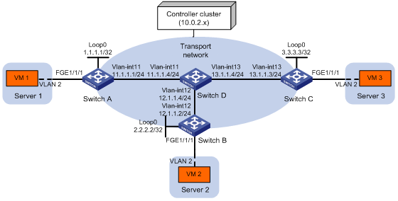
Configuration procedure
1. Configure IP addresses and unicast routing settings:
# Assign IP addresses to interfaces, as shown in Figure 13. (Details not shown.)
# Configure OSPF on all transport network switches (Switches A through D). (Details not shown.)
2. Configure Switch A:
# Enable L2VPN.
<SwitchA> system-view
[SwitchA] l2vpn enable
# Initiate an SSL connection to the controller, and enable the OVSDB service.
[SwitchA] ovsdb server private-key flash:/ovsclient-privkey.pem
[SwitchA] ovsdb server certificate flash:/ovsclient-cert.pem
[SwitchA] ovsdb server ca-certificate flash:/vswitchd.cacert bootstrap
[SwitchA] ovsdb server ssl 10.0.2.15 port 6632
[SwitchA] ovsdb server enable
# Enable VTEP mode.
[SwitchA] vtep enable
# Assign an IP address to Loopback 0. Specify the IP address as the global source address for VXLAN tunnels.
[SwitchA] interface loopback0
[SwitchA-LoopBack0] ip address 1.1.1.1 255.255.255.255
[SwitchA-LoopBack0] quit
[SwitchA] tunnel global source-address 1.1.1.1
# Specify the site-facing interface FortyGigE 1/1/1 as a VTEP access port.
[SwitchA] interface fortygige 1/1/1
[SwitchA-FortyGigE1/1/1] vtep access port
[SwitchA-FortyGigE1/1/1] quit
3. Configure Switch B:
# Enable L2VPN.
<SwitchB> system-view
[SwitchB] l2vpn enable
# Initiate an SSL connection to the controller, and enable the OVSDB service.
[SwitchB] ovsdb server private-key flash:/ovsclient-privkey.pem
[SwitchB] ovsdb server certificate flash:/ovsclient-cert.pem
[SwitchB] ovsdb server ca-certificate flash:/vswitchd.cacert bootstrap
[SwitchB] ovsdb server ssl 10.0.2.15 port 6632
[SwitchB] ovsdb server enable
# Enable VTEP mode.
[SwitchB] vtep enable
# Assign an IP address to Loopback 0. Specify the IP address as the global source address for VXLAN tunnels.
[SwitchB] interface loopback0
[SwitchB-LoopBack0] ip address 2.2.2.2 255.255.255.255
[SwitchB-LoopBack0] quit
[SwitchB] tunnel global source-address 2.2.2.2
# Specify the site-facing interface FortyGigE 1/1/1 as a VTEP access port.
[SwitchB] interface fortygige 1/1/1
[SwitchB-FortyGigE1/1/1] vtep access port
[SwitchB-FortyGigE1/1/1] quit
4. Configure Switch C:
# Enable L2VPN.
<SwitchC> system-view
[SwitchC] l2vpn enable
# Establish an active SSL connection to the controller, and enable the OVSDB service.
[SwitchC] ovsdb server private-key flash:/ovsclient-privkey.pem
[SwitchC] ovsdb server certificate flash:/ovsclient-cert.pem
[SwitchC] ovsdb server ca-certificate flash:/vswitchd.cacert bootstrap
[SwitchC] ovsdb server ssl 10.0.2.15 port 6632
[SwitchC] ovsdb server enable
# Enable VTEP mode.
[SwitchC] vtep enable
# Assign an IP address to Loopback 0. Specify the IP address as the global source address for VXLAN tunnels.
[SwitchC] interface loopback0
[SwitchC-LoopBack0] ip address 3.3.3.3 255.255.255.255
[SwitchC-LoopBack0] quit
[SwitchC] tunnel global source-address 3.3.3.3
# Specify the site-facing interface FortyGigE 1/1/1 as a VTEP access port.
[SwitchC] interface fortygige 1/1/1
[SwitchC-FortyGigE1/1/1] vtep access port
[SwitchC-FortyGigE1/1/1] quit
5. Configure VXLAN settings on the controller. (Details not shown.)
Verifying the configuration
1. Verify the VXLAN settings on the VTEPs. This example uses Switch A.
# Verify that the VXLAN tunnel interfaces on the VTEP are up.
[SwitchA] display interface tunnel 1
Tunnel1
Current state: UP
Line protocol state: UP
Description: Tunnel1 Interface
Bandwidth: 64 kbps
Maximum transmission unit: 1464
Internet protocol processing: Disabled
Last clearing of counters: Never
Tunnel source 1.1.1.1, destination 2.2.2.2
Tunnel protocol/transport UDP_VXLAN/IP
# Verify that the VXLAN tunnels have been assigned to the VXLAN.
[SwitchA] display l2vpn vsi verbose
VSI Name: evpn2014
VSI Index : 0
VSI State : Up
MTU : 1500
Bandwidth : -
Broadcast Restrain : -
Multicast Restrain : -
Unknown Unicast Restrain: -
MAC Learning : Enabled
MAC Table Limit : -
Drop Unknown : -
Flooding : Enabled
Statistics : Disabled
VXLAN ID : 10
Tunnels:
Tunnel Name Link ID State Type Flooding proxy
Tunnel1 0x5000001 Up Manual Disabled
Tunnel2 0x5000002 Up Manual Disabled
ACs:
AC Link ID State
FGE1/1/1 srv2 0 Up
# Verify that the VTEP has learned the MAC addresses of remote VMs.
<SwitchA> display l2vpn mac-address
MAC Address State VSI Name Link ID/Name Aging
cc3e-5f9c-6cdb Dynamic evpn2014 Tunnel1 Aging
cc3e-5f9c-23dc Dynamic evpn2014 Tunnel2 Aging
--- 2 mac address(es) found ---
2. Verify that VM 1, VM 2, and VM 3 can ping each other. (Details not shown.)
Flood proxy configuration example
Network requirements
As shown in Figure 14:
· Configure the controller to deploy VXLAN 10 on Switch A, Switch B, and Switch C to provide Layer 2 connectivity for the VMs across the network sites.
· Configure the controller to deploy remote MAC address entries to VTEPs.
· Use a flood proxy server to forward inter-site flood traffic.
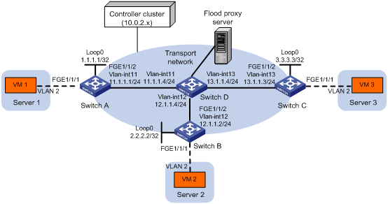
Configuration procedure
1. Configure IP addresses and unicast routing settings:
# Assign IP addresses to interfaces, as shown in Figure 14. (Details not shown.)
# Configure OSPF on all transport network switches (Switches A through D). (Details not shown.)
2. Configure Switch A:
# Enable L2VPN.
<SwitchA> system-view
[SwitchA] l2vpn enable
# Establish an SSL connection to the controller, and enable the OVSDB service.
[SwitchA] ovsdb server private-key flash:/ovsclient-privkey.pem
[SwitchA] ovsdb server certificate flash:/ovsclient-cert.pem
[SwitchA] ovsdb server ca-certificate flash:/vswitchd.cacert bootstrap
[SwitchA] ovsdb server ssl 10.0.2.15 port 6632
[SwitchA] ovsdb server enable
# Enable VTEP mode.
[SwitchA] vtep enable
# Assign an IP address to Loopback 0. Specify the IP address as the global source address for VXLAN tunnels.
[SwitchA] interface loopback 0
[SwitchA-LoopBack0] ip address 1.1.1.1 255.255.255.255
[SwitchA-LoopBack0] quit
[SwitchA] tunnel global source-address 1.1.1.1
# Specify the site-facing interface FortyGigE 1/1/1 as a VTEP access port.
[SwitchA] interface fortygige 1/1/1
[SwitchA-FortyGigE1/1/1] vtep access port
[SwitchA-FortyGigE1/1/1] quit
# Disable source MAC check on the transport-facing interface FortyGigE 1/1/2.
[SwitchA] interface fortygige 1/1/2
[SwitchA-FortyGigE1/1/2] undo mac-address static source-check enable
[SwitchA-FortyGigE1/1/2] quit
# Disable remote-MAC address learning.
[SwitchA] vxlan tunnel mac-learning disable
# Enable flood proxy on all multicast VXLAN tunnels.
[SwitchA] vxlan tunnel service node
3. Configure Switch B:
# Enable L2VPN.
<SwitchB> system-view
[SwitchB] l2vpn enable
# Establish an SSL connection to the controller, and enable the OVSDB service.
[SwitchB] ovsdb server private-key flash:/ovsclient-privkey.pem
[SwitchB] ovsdb server certificate flash:/ovsclient-cert.pem
[SwitchB] ovsdb server ca-certificate flash:/vswitchd.cacert bootstrap
[SwitchB] ovsdb server ssl 10.0.2.15 port 6632
[SwitchB] ovsdb server enable
# Enable VTEP mode.
[SwitchB] vtep enable
# Assign an IP address to Loopback 0. Specify the IP address as the global source address for VXLAN tunnels.
[SwitchB] interface loopback0
[SwitchB-LoopBack0] ip address 2.2.2.2 255.255.255.255
[SwitchB-LoopBack0] quit
[SwitchB] tunnel global source-address 2.2.2.2
# Specify the site-facing interface FortyGigE 1/1/1 as a VTEP access port.
[SwitchB] interface fortygige 1/1/1
[SwitchB-FortyGigE1/1/1] vtep access port
[SwitchB-FortyGigE1/1/1] quit
# Disable source MAC check on the transport-facing interface FortyGigE 1/1/2.
[SwitchB] interface fortygige 1/1/2
[SwitchB-FortyGigE1/1/2] undo mac-address static source-check enable
[SwitchB-FortyGigE1/1/2] quit
# Disable remote-MAC address learning.
[SwitchB] vxlan tunnel mac-learning disable
# Enable flood proxy on all multicast VXLAN tunnels.
[SwitchB] vxlan tunnel service node
4. Configure Switch C:
# Enable L2VPN.
<SwitchC> system-view
[SwitchC] l2vpn enable
# Establish an SSL connection to the controller, and enable the OVSDB service.
[SwitchC] ovsdb server ssl 10.0.2.15 port 6632
[SwitchC] ovsdb server private-key flash:/ovsclient-privkey.pem
[SwitchC] ovsdb server certificate flash:/ovsclient-cert.pem
[SwitchC] ovsdb server ca-certificate flash:/vswitchd.cacert bootstrap
[SwitchC] ovsdb server enable
# Enable VTEP mode.
[SwitchC] vtep enable
# Assign an IP address to Loopback 0. Specify the IP address as the global source address for VXLAN tunnels.
[SwitchC] interface loopback0
[SwitchC-LoopBack0] ip address 3.3.3.3 255.255.255.255
[SwitchC-LoopBack0] quit
[SwitchC] tunnel global source-address 3.3.3.3
# Specify the site-facing interface FortyGigE 1/1/1 as a VTEP access port.
[SwitchC] interface fortygige 1/1/1
[SwitchC-FortyGigE1/1/1] vtep access port
[SwitchC-FortyGigE1/1/1] quit
# Disable source MAC check on the transport-facing interface FortyGigE 1/1/2.
[SwitchC] interface fortygige 1/1/2
[SwitchC-FortyGigE1/1/2] undo mac-address static source-check enable
[SwitchC-FortyGigE1/1/2] quit
# Disable remote-MAC address learning.
[SwitchC] vxlan tunnel mac-learning disable
# Enable flood proxy on all multicast VXLAN tunnels.
[SwitchC] vxlan tunnel service node
5. Configure VXLAN settings on the controller. (Details not shown.)
Verifying the configuration
1. Verify the VXLAN settings on the VTEPs. This example uses Switch A.
# Verify that the VXLAN tunnel interfaces on the VTEP are up.
[SwitchA] display interface tunnel 1
Tunnel1
Current state: UP
Line protocol state: UP
Description: Tunnel1 Interface
Bandwidth: 64 kbps
Maximum transmission unit: 1464
Internet protocol processing: Disabled
Last clearing of counters: Never
Tunnel source 1.1.1.1, destination 2.2.2.2
Tunnel protocol/transport UDP_VXLAN/IP
# Verify that VXLAN tunnels have been established to reach the remote sites and the flood proxy server.
[SwitchA] display l2vpn vsi verbose
VSI Name: evpn2014
VSI Index : 0
VSI State : Up
MTU : 1500
Bandwidth : -
Broadcast Restrain : -
Multicast Restrain : -
Unknown Unicast Restrain: -
MAC Learning : Enabled
MAC Table Limit : -
Drop Unknown : -
Flooding : Enabled
Statistics : Disabled
VXLAN ID : 10
Tunnels:
Tunnel Name Link ID State Type Flooding proxy
Tunnel1 0x5000001 Up Manual Disabled
Tunnel2 0x5000002 Up Manual Disabled
Tunnel3 0x5000003 Up Manual Enabled
ACs:
AC Link ID State
FGE1/1/1 srv2 0 Up
# Verify that the VTEP has obtained the MAC addresses of remote VMs from the controller.
<SwitchA> display l2vpn mac-address
MAC Address State VSI Name Link ID/Name Aging
cc3e-5f9c-6cdb Static evpn2014 Tunnel1 NotAging
cc3e-5f9c-23dc Static evpn2014 Tunnel2 NotAging
--- 2 mac address(es) found ---
2. Verify that VM 1, VM 2, and VM 3 can ping each other. (Details not shown.)