- Table of Contents
- Related Documents
-
| Title | Size | Download |
|---|---|---|
| 01-OpenFlow configuration | 263.99 KB |
Contents
OpenFlow configuration task list
Configuring OpenFlow instances
Configuring the OpenFlow instance mode
Creating flow tables for an OpenFlow instance
Setting the maximum number of flow entries
Configuring inband management VLANs
Configuring OpenFlow to forbid MAC address learning
Forbidding an OpenFlow instance to report the specified types of ports to controllers
Configuring the default action of table-miss flow entries
Activating or reactivating an OpenFlow instance
Configuring controllers for an OpenFlow switch
Configuring controllers and main connections
Setting the connection interruption mode
Configuring OpenFlow to support dynamic MAC addresses
Enabling packet loss prevention for OpenFlow forwarding
Displaying and maintaining OpenFlow
OpenFlow configuration example
Appendixes A Application restrictions
Restrictions for merging the action list into the action set
Packet-out messages restrictions
Packet-in messages restrictions
Flow table modification messages restrictions
Support capabilities of the MAC-IP flow table
MAC-IP flow table restrictions
Table-miss flow entry of MAC-IP flow tables
MAC-IP flow table cooperating with extensibility flow table
Software-Defined Networking (SDN) was developed to meet the growing requirements of virtualization technologies and data networks. SDN uses software to separate controlling functions from data forwarding, and provides simple, flexible device operations and high extensibility.
OpenFlow is the communication interface between a controller and network devices to implement SDN. With OpenFlow, you can perform centralized data forwarding management for physical and virtual devices.
Overview
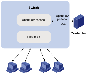
OpenFlow separates the data forwarding and routing decision functions. It keeps the flow-based forwarding function and employs a separate controller to make routing decisions. A switch communicates with the controller through an OpenFlow channel. An OpenFlow channel can be encrypted by using TLS or run directly over TCP. An OpenFlow switch exchanges control messages with the controller through an OpenFlow channel to perform the following operations:
· Receive flow table entries or data from the controller.
· Report information to the controller.
Unless otherwise stated, a switch refers to an OpenFlow switch throughout this document.
Figure 1 OpenFlow network diagram
OpenFlow switch
OpenFlow switches include the following types:
· OpenFlow-only—Supports only OpenFlow operation.
· OpenFlow-hybrid—Supports both OpenFlow operation and traditional Ethernet switching operation. Switches of this series are OpenFlow-hybrid switches.
OpenFlow port
|
|
IMPORTANT: The loopback interfaces cannot be used as OpenFlow ports. |
OpenFlow supports the following types of ports:
· Physical port—Corresponds to a hardware interface of a switch, such as an Ethernet interface. A physical port can be either an ingress port or an output port.
· Logical port—Does not correspond to a hardware interface of a switch and might be defined by non-OpenFlow methods, such as an aggregate interface. A logical port can be either an ingress port or an output port.
· Reserved port—Defined by OpenFlow to specify forwarding actions. Reserved ports include the following types:
? All—All OpenFlow ports that can be used to forward a packet.
? Controller—OpenFlow controller.
? Local—Local CPU.
? Normal—Normal forwarding process.
? Flood—Flooding.
Except the Any type, all reserved ports can be used only as output ports. Only ports of Controller and Local types can be used as input ports.
OpenFlow instance
You can configure one or more OpenFlow instances on the same device. A controller considers each OpenFlow instance as a separate OpenFlow switch and deploys forwarding instructions to it.
In this chapter, an OpenFlow switch is the same as an OpenFlow instance, unless otherwise specified.
Associated VLAN
When an OpenFlow instance is associated with VLANs, the flow tables take effect on packets only within those VLANs.
Activation and reactivation
The configurations for an OpenFlow instance take effect only after the OpenFlow instance is activated.
The controller can deploy flow entries to an OpenFlow instance only after the OpenFlow instance reports the following information to the controller:
· Support capabilities for OpenFlow.
· Ports that belongs to the OpenFlow instance.
An activated OpenFlow instance needs to be reactivated when any of the OpenFlow instance configurations is changed.
After reactivation, the OpenFlow instance is disconnected from all controllers and then reconnected to them.
OpenFlow instance port
An OpenFlow instance sends information about following ports to the controller:
· Physical ports.
· Logical ports.
· Reserved ports of the Local type.
In loosen mode, a port belongs to the OpenFlow instance when VLANs associated with the OpenFlow instance overlap with the port's allowed VLANs. Otherwise, a port belongs to an OpenFlow instance only when VLANs associated with the OpenFlow instance are within the port's allowed VLAN list.
OpenFlow flow table
An OpenFlow switch matches packets with one or more user-defined flow tables. A flow table contains flow entries, and packets are matched based on the matching precedence of flow entries.
OpenFlow flow tables include the following types:
· MAC-IP—Combines the MAC address table and FIB table.
A MAC-IP flow table provides the following match fields:
? Destination MAC address.
? VLAN.
? Destination IP address.
A MAC-IP flow table provides the following actions:
? Modifying the destination MAC address.
? Modifying the source MAC address.
? Modifying the VLAN.
? Specifying the output port.
· Extensibility—Combines Ternary Content Addressable Memory (TCAM) tables and tables programmed by software. An extensibility flow table provides more match fields and actions than a MAC-IP flow table, such as destination MAC address, destination IP address, VLAN priority, TCP source port, and TCP destination port.
Flow entry
Figure 2 Flow entry components
![]()
A flow entry contains the following fields:
· Match fields—Matching rules of the flow entry. These contain the ingress port, packet headers, and metadata specified by the previous table.
· Priority—Matching precedence of the flow entry. When a packet is matched with the flow table, only the highest priority flow entry that matches the packet is selected.
· Counters—Counts of the packets that match the flow entry.
· Instructions—To modify the action set or pipeline processing. These include the following types:
? Meter—Directs the packets to the specified meter to rate-limit the packets.
? Apply-Actions—Applies the specified actions in the action list immediately.
? Clear-Actions—Clears all actions in the action set immediately.
? Write-Actions—Modifies all actions in the action set immediately.
? Write-Metadata—Modifies packets between two flow tables if multiple flow tables exist.
? Goto-Table—Indicates the next flow table in the processing pipeline.
Actions are executed in one of the following ways:
? Action Set—When the instruction set of a flow entry does not contain a Goto-Table instruction, pipeline processing stops and the actions in the action set are executed. An action set contains a maximum of one action of each type.
? Action List—The actions in the action list are executed immediately in the order specified by the action list. The effect of those actions is cumulative.
Actions include the following types:
? (Required.) Output—The Output action forwards a packet to the specified OpenFlow port. OpenFlow switches must support forwarding packets to physical ports, logical ports, and reserved ports.
? (Required.) Drop—No explicit action exists to represent drops. Packets whose action sets have no output actions are dropped. Typically, packets are dropped due to empty instruction sets, empty action sets, or the executing a Clear-Actions instruction.
? (Required.) Group—Process the packet through the specified group. The exact interpretation depends on group type.
? (Optional.) Set-Queue—The Set-Queue action sets the queue ID for a packet. When the packet is forwarded to a port by the output action, the packet is assigned to the queue attached to this port for scheduling and forwarding. The forwarding behavior is dictated by the configuration of the queue and provides basic QoS support.
? (Optional.) Set-Field—The Set-Field actions are identified by their field type and modify the values of corresponding header fields in the packet. Set-Field actions are always applied to the outermost header. For example, a Set VLAN ID action always sets the ID of the outermost VLAN tag.
· Timeouts—Maximum amount of idle time or hard time for the flow entry.
? idle time—The flow entry is removed when it has matched no packets during the idle time.
? hard time—The flow entry is removed when the hard time timeout is exceeded, whether or not it has matched packets.
· Cookie—Flow entry identifier specified by the controller.
Table-miss flow entry
Every flow table must support a table-miss flow entry to process table misses. The table-miss flow entry specifies how to process packets that were not matched by other flow entries in the flow table.
The table-miss flow entry wildcards all match fields (all fields omitted) and has the lowest priority 0.
The table-miss flow entry behaves in most ways like any other flow entry.
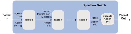
OpenFlow pipeline
The OpenFlow pipeline processing defines how packets interact with flow tables contained by a switch.
The flow tables of an OpenFlow switch are sequentially numbered, starting at 0. The packet is first matched with flow entries of the first flow table, which is flow table 0. A flow entry can only direct a packet to a flow table number that is greater than its own flow table number.
When a packet matches a flow entry, the OpenFlow switch updates the action set for the packet and passes the packet to the next flow table. In the last flow table, the OpenFlow switch executes all actions to modify packet contents and specify the output port for packet forwarding. If the instruction set of one of the flow tables contains an action list, the OpenFlow switch executes the actions to modify a copy of the packet immediately in this table.
Figure 3 OpenFlow forwarding workflow
Group table
The ability for a flow entry to point to a group enables OpenFlow to represent additional methods of forwarding. A group table contains group entries.
Figure 4 Group entry components
![]()
A group entry contains the following fields:
· Group Identifier—A 32 bit unsigned integer uniquely identifying the group.
· Group Type—Type of the group:
? All—Execute all buckets in the group. This group is used for multicast or broadcast forwarding.
· Counters—Updated when packets are processed by a group.
· Action Buckets—An ordered list of action buckets, where each action bucket contains a set of actions to execute and associated parameters.
Meter table
Meters enable OpenFlow to implement various simple QoS operations, such as rate-limiting. A group table contains meter entries.
Figure 5 Meter entry components
![]()
A meter entry contains the following fields:
· Meter Identifier—A 32 bit unsigned integer uniquely identifying the meter.
· Meter Bands—Each meter can have one or more meter bands. Each band specifies the rate at which the band applies and the way packets should be processed. If the current rate of packets exceeds the rate of multiple bands, the band with the highest configured rate is used.
· Counters—Updated when packets are processed by a meter.
Figure 6 Band components
![]()
A meter band contains:
· Band Type—Packet processing methods. Packets that exceed the band rate are dropped.
· Rate—Defines the lowest rate at which the band can apply.
· Counters—Updated when packets are processed by a band.
· Type Specific Arguments—Some band types have optional arguments.
OpenFlow channel
The OpenFlow channel is the interface that connects each OpenFlow switch to a controller. The controller uses the OpenFlow channel to exchange control messages with the switch to perform the following operations:
· Configure and manage the switch.
· Receive events from the switch.
· Send packets out the switch.
The OpenFlow channel is usually encrypted by using TLS. Also, an OpenFlow channel can be run directly over TCP.
The OpenFlow protocol supports the following message types: controller-to-switch, asynchronous, and symmetric. Each message type has its own subtypes.
Controller-to-switch messages
Controller-to-switch messages are initiated by the controller and used to directly manage or inspect the state of the switch. Controller-to-switch messages might or might not require a response from the switch.
The controller-to-switch messages include the following subtypes:
· Features—The controller requests the basic capabilities of a switch by sending a features request. The switch must respond with a features reply that specifies the basic capabilities of the switch.
· Configuration—The controller sets and queries configuration parameters in the switch. The switch only responds to a query from the controller.
· Modify-State—The controller sends Modify-State messages to manage state on the switches. Their primary purpose is to add, delete, and modify flow or group entries in the OpenFlow tables and to set switch port properties.
· Read-State—The controller sends Read-State messages to collect various information from the switch, such as current configuration and statistics.
· Packet-out—These are used by the controller to send packets out of the specified port on the switch, or to forward packets received through packet-in messages. Packet-out messages must contain a full packet or a buffer ID representing a packet stored in the switch. The message must also contain a list of actions to be applied in the order they are specified. An empty action list drops the packet.
· Barrier—Barrier messages are used to confirm the completion of the previous operations. The controller send s Barrier request. The switch must send a Barrier reply when all the previous operations are complete.
· Role-Request—Role-Request messages are used by the controller to set the role of its OpenFlow channel, or query that role. It is typically used when the switch connects to multiple controllers.
· Asynchronous-Configuration—These are used by the controller to set an additional filter on the asynchronous messages that it wants to receive, or to query that filter. It is typically used when the switch connects to multiple controllers.
Asynchronous messages
Switches send asynchronous messages to controllers to inform a packet arrival or switch state change. For example, when a flow entry is removed due to timeout, the switch sends a flow-removed message to inform the controller.
The asynchronous messages include the following subtypes:
· Packet-In—Transfer the control of a packet to the controller. For all packets forwarded to the Controller reserved port using a flow entry or the table-miss flow entry, a packet-in event is always sent to controllers. Other processing, such as TTL checking, can also generate packet-in events to send packets to the controller. The packet-in events can include the full packet or can be configured to buffer packets in the switch. If the packet-in event is configured to buffer packets, the packet-in events contain only some fraction of the packet header and a buffer ID. The controller processes the full packet or the combination of the packet header and the buffer ID. Then, the controller sends a packet-out message to direct the switch to process the packet.
· Flow-Removed—Inform the controller about the removal of a flow entry from a flow table. These are generated due to a controller flow delete request or the switch flow expiry process when one of the flow timeouts is exceeded.
· Port-status—Inform the controller of a state or setting change on a port.
· Error—Inform the controller of a problem or error.
Symmetric messages
Symmetric messages are sent without solicitation, in either direction.
The symmetric messages contain the following subtypes:
· Hello—Hello messages are exchanged between the switch and controller upon connection startup.
· Echo—Echo request or reply messages can be sent from either the switch or the controller, and must return an echo reply. They are mainly used to verify the liveness of a controller-switch connection, and might also be used to measure its latency or bandwidth.
· Experimenter—This is a staging area for features meant for future OpenFlow revisions.
Protocols and standards
OpenFlow Switch Specification Version 1.3.1
OpenFlow configuration task list
Configuring OpenFlow instances
Creating an OpenFlow instance
|
Step |
Command |
Remarks |
|
1. Enter system view. |
system-view |
N/A |
|
2. Create an OpenFlow instance and enter OpenFlow instance view. |
openflow instance instance-id |
By default, no OpenFlow instance exists. |
|
3. (Optional.) Set a description for the OpenFlow instance. |
description text |
By default, an OpenFlow instance does not have a description. |
Configuring the OpenFlow instance mode
An OpenFlow instance operates in one of the following modes:
· VLAN mode—When the VLAN mode is enabled for an OpenFlow instance, the flow entries take effect only on packets within VLANs associated with the OpenFlow instance.
· Global mode—When the global mode is enabled for an OpenFlow instance, the flow entries take effect on packets within the network. All interfaces on the device belong to the OpenFlow instance, including VLAN interfaces and Layer 2 or Layer 3 Ethernet interfaces.
When you associate an OpenFlow instance with VLANs, follow these guidelines:
· Do not associate multiple OpenFlow instances with the same VLAN. Otherwise, VLAN traffic cannot be correctly processed.
· When you activate an OpenFlow instance that is associated with non-existent VLANs, the system automatically creates these VLANs. Do not delete any of the associated VLANs after the OpenFlow instance is activated.
· Do not configure the BFD MAD function on the VLAN interface for a VLAN that is associated with an OpenFlow instance. For more information about the BFD MAD function, see IRF Configuration Guide.
To configure the OpenFlow instance mode:
|
Step |
Command |
Remarks |
|
1. Enter system view. |
system-view |
N/A |
|
2. Enter OpenFlow instance view. |
openflow instance instance-id |
N/A |
|
3. Configure the OpenFlow instance mode. |
· Enable the global mode for the OpenFlow
instance: · Associate the OpenFlow instance with VLANs. |
Use either command. By default, an OpenFlow instance is in the VLAN mode and is not associated with any VLAN. By default, an OpenFlow instance is not associated with any VLAN. If you execute the classification global and classification vlan commands multiple times, the most recent configuration takes effect. |
Creating flow tables for an OpenFlow instance
|
Step |
Command |
Remarks |
|
1. Enter system view. |
system-view |
N/A |
|
2. Enter OpenFlow instance view. |
openflow instance instance-id |
N/A |
|
3. Configure the flow table type and the flow table ID. |
flow-table { extensibility table-id | mac-ip table-id }* |
By default, an OpenFlow instance contains one extensibility flow table with an ID of 0. An OpenFlow instance supports only one MAC-IP flow table and one extensibility flow table. If you execute the command multiple times, the most recent configuration takes effect. The ID of the MAC-IP flow table must be smaller than that of the extensibility flow table. |
Setting the controller mode
An OpenFlow instance can connect to one or more controllers, depending on the controller mode the OpenFlow instance uses:
· Single—The OpenFlow instance connects to only one controller at a time. When communication with the current controller fails, the OpenFlow instance uses another controller. In this mode, an OpenFlow instance attempts to connect to a controller one by one in ascending order of controller ID until it successfully connects to a controller. If multiple controllers that are configured for the OpenFlow instance are unreachable, it might take a long time for the OpenFlow instance to connect to a reachable controller.
· Multiple—The OpenFlow instance can simultaneously connect to multiple controllers. When communication with any controller fails, the OpenFlow instance attempts to reconnect to the controller after a reconnection interval.
To set the controller mode for an OpenFlow instance:
|
Step |
Command |
Remarks |
|
1. Enter system view. |
system-view |
N/A |
|
2. Enter OpenFlow instance view. |
openflow instance instance-id |
N/A |
|
3. Set the controller mode. |
controller mode { multiple | single } |
By default, the controller mode is multiple. |
Setting the maximum number of flow entries
You can set the maximum number of flow entries that an extensibility flow table supports. When the maximum number is reached, the OpenFlow instance does not accept new flow entries for that table and sends a deployment failure notification to the controller.
To set the maximum number of flow entries that an extensibility flow table supports:
|
Step |
Command |
Remarks |
|
1. Enter system view. |
system-view |
N/A |
|
2. Enter OpenFlow instance view. |
openflow instance instance-id |
N/A |
|
3. Set the maximum number of extensibility flow entries. |
flow-entry max-limit limit-value |
By default, an OpenFlow extensibility flow table supports up to 65535 flow entries. |
Configuring inband management VLANs
Inband management VLANs are used to establish connections between an OpenFlow instance and controllers.
When the inband management VLANs are configured, the data packets within the inband management VLANs are not forwarded through OpenFlow. The ports that are assigned to only inband management VLANs are not OpenFlow ports. Before configuring inband management VLANs, you must plan the network.
To configure inband management VLANs:
|
Step |
Command |
Remarks |
|
1. Enter system view. |
system-view |
N/A |
|
2. Enter OpenFlow instance view. |
openflow instance instance-id |
N/A |
|
3. Configure inband management VLANs. |
in-band management vlan vlan-list |
By default, no inband management VLAN is configured. The inband management VLANs of an OpenFlow instance must be within the list of the VLANs that are associated with the OpenFlow instance. This feature is applicable only to OpenFlow instances that are in the VLAN mode. |
Configuring OpenFlow to forbid MAC address learning
|
Step |
Command |
Remarks |
|
1. Enter system view. |
system-view |
N/A |
|
2. Enter OpenFlow instance view. |
openflow instance instance-id |
N/A |
|
3. Forbid MAC address learning for VLANs associated with the OpenFlow instance. |
mac-learning forbidden |
By default, MAC address learning is allowed for VLANs associated with an OpenFlow instance. The configuration does not take effect on inband management VLANs. This feature is applicable only to OpenFlow instances that are in the VLAN mode. |
Forbidding an OpenFlow instance to report the specified types of ports to controllers
|
Step |
Command |
Remarks |
|
1. Enter system view. |
system-view |
N/A |
|
2. Enter OpenFlow instance view. |
openflow instance instance-id |
N/A |
|
3. Forbid the OpenFlow instance to report the specified types of ports to controllers. |
forbidden port { vlan-interface | vsi-interface } * |
By default, all ports that belong to an OpenFlow instance are reported to the controllers. |
Configuring the default action of table-miss flow entries
|
Step |
Command |
Remarks |
|
1. Enter system view. |
system-view |
N/A |
|
2. Enter OpenFlow instance view. |
openflow instance instance-id |
N/A |
|
3. Change the default action of the table-miss flow entry to forward packets to the normal pipeline. |
By default, the default action of the table-miss flow entry is to drop packets after the OpenFlow instance is activated and before the controller deploys flow entries. |
Setting the datapath ID
The datapath ID uniquely identifies an OpenFlow switch (OpenFlow instance). Do not set the same datapath ID for different OpenFlow switches.
To set the datapath ID:
|
Step |
Command |
Remarks |
|
1. Enter system view. |
system-view |
N/A |
|
2. Enter OpenFlow instance view. |
openflow instance instance-id |
N/A |
|
3. Set the datapath ID. |
datapath-id id |
By default, the datapath ID of an OpenFlow instance contains the instance ID and the bridge MAC address of the device. The upper 16 bits are the instance ID and the lower 48 bits are the bridge MAC address of the device. |
Activating or reactivating an OpenFlow instance
|
|
CAUTION: Reactivating an OpenFlow instance refreshes the configuration data and interrupts communication with the controllers. |
To activate or reactivate an OpenFlow instance:
|
Step |
Command |
Remarks |
|
1. Enter system view. |
system-view |
N/A |
|
2. Enter OpenFlow instance view. |
openflow instance instance-id |
N/A |
|
3. Activate or reactivate the OpenFlow instance. |
active instance |
By default, an OpenFlow instance is not activated. |
Configuring controllers for an OpenFlow switch
· Equal—In this role, the controller has full access to the switch and is equal to other controllers in the same role. By default, the controller receives all switch asynchronous messages such as packet-in and flow-removed messages. The controller can send controller-to-switch messages to modify the state of the switch.
· Master—This role is similar to the Equal role and has full access to the switch. The difference is that up to one controller in this role is allowed for a switch.
· Slave—In this role, the controller has read-only access to the switch.
The controller cannot send controller-to-switch messages to perform the following operations:
? Deploy flow entries, group entries, and meter entries.
? Modify the port and switch configurations.
? Send packet-out messages.
By default, the controller does not receive switch asynchronous messages except Port-status messages. The controller can send Asynchronous-Configuration messages to set the asynchronous message types it wants to receive.
When OpenFlow operation is initiated, a switch is simultaneously connected to multiple controllers in Equal state. A controller can request its role to be changed at any time.
Configuring controllers and main connections
An OpenFlow switch supports up to 64 controllers. However, the OpenFlow channel between the OpenFlow switch and each controller can have only one main connection. The main connection processes control messages to complete operations such as deploying entries, obtaining data, and sending information. The main connection must be a reliable connection using TCP or SSL.
To specify a controller for an OpenFlow switch and configure the main connection to the controller:
|
Step |
Command |
Remarks |
|
1. Enter system view. |
system-view |
N/A |
|
2. Enter OpenFlow instance view. |
openflow instance instance-id |
N/A |
|
3. Specify a controller and configure the main connection to the controller. |
controller id address { ip ip-address | ipv6 ipv6-address } [ port port-number ] [ local address { ip ip-address | ipv6 ipv6-address } [ port port-number ] ] [ ssl ssl-policy-name ][ vrf vrf-name ] |
By default, an OpenFlow instance is not configured with any main connection. |
Setting the connection interruption mode
An OpenFlow switch is set to either of the following modes when it is disconnected from all controllers:
· Secure—In this mode, the OpenFlow switch forwards traffic based on flow tables and does not delete unexpired flow entries.
· Standalone—The OpenFlow switch uses the normal forwarding process.
The OpenFlow switch forwards traffic based on flow tables when it reconnects to a controller successfully.
To set the connection interruption mode for an OpenFlow switch:
|
Step |
Command |
Remarks |
|
1. Enter system view. |
system-view |
N/A |
|
2. Enter OpenFlow instance view. |
openflow instance instance-id |
N/A |
|
3. Set the connection interruption mode. |
fail-open mode { secure | standalone } |
By default, the secure mode is used. |
Setting OpenFlow timers
An OpenFlow switch supports the following timers:
· Connection detection interval—Interval at which the OpenFlow switch sends an Echo Request message to a controller. When the OpenFlow switch receives no Echo Reply message within three connection detection intervals, the OpenFlow switch is disconnected from the controller.
· Reconnection interval—Interval for the OpenFlow switch to wait before it attempts to reconnect to a controller.
To set OpenFlow timers for an OpenFlow switch:
|
Step |
Command |
Remarks |
|
1. Enter system view. |
system-view |
N/A |
|
2. Enter OpenFlow instance view. |
openflow instance instance-id |
N/A |
|
3. Set the connection detection interval. |
controller echo-request interval interval-value |
By default, the connection detection interval is 5 seconds. To reduce the CPU load, H3C recommends that you set the connection detection interval to a large value. |
|
4. Set the reconnection interval. |
controller connect interval interval-value |
By default, the reconnection interval is 60 seconds. |
Configuring OpenFlow to support dynamic MAC addresses
You can configure OpenFlow to support querying and deleting dynamic MAC addresses in MAC-IP flow tables.
To configure OpenFlow to support dynamic MAC addresses:
|
Step |
Command |
Remarks |
|
1. Enter system view. |
system-view |
N/A |
|
2. Enter OpenFlow instance view. |
openflow instance instance-id |
N/A |
|
3. Configure OpenFlow to support dynamic MAC addresses. |
mac-ip dynamic-mac aware |
By default, OpenFlow prohibits controllers from querying and deleting dynamic MAC addresses. This feature is applicable only to OpenFlow instances that are in the VLAN mode. |
Enabling packet loss prevention for OpenFlow forwarding
In networks that require high OpenFlow forwarding performance, packet loss might occur on the switch during the flow entry deployment process. The packet loss then causes OpenFlow forwarding to fail. You can enable packet loss prevention to ensure successful OpenFlow forwarding without packet loss.
When this feature is configured, ACLs cannot match packets by IPv6 address.
After you enable or disable packet loss prevention, save the configuration and restart the switch to make the configuration take effect.
To enable packet loss prevention for OpenFlow forwarding:
|
Step |
Command |
Remarks |
|
1. Enter system view. |
system-view |
N/A |
|
2. Enable packet loss prevention for OpenFlow forwarding. |
openflow lossless enable |
By default, the packet loss prevention feature for OpenFlow forwarding is disabled. |
Displaying and maintaining OpenFlow
Execute display commands in any view.
|
Task |
Command |
|
Display the detailed information for an OpenFlow instance. |
display openflow instance [ instance-id ] |
|
Display flow table entries for an OpenFlow instance. |
display openflow instance instance-id flow-table [ table-id ] |
|
Display controller information for an OpenFlow instance. |
display openflow instance instance-id controller |
|
Display group table information for an OpenFlow instance. |
display openflow instance instance-id group [ group-id ] |
|
Display meter information for an OpenFlow instance. |
display openflow instance instance-id meter [ meter-id ] |
|
Display summary OpenFlow instance information. |
display openflow summary |
|
Clear statistics on packets that a controller sends and receives for an OpenFlow instance. |
reset openflow instance instance-id controller [ controller-id ] statistics |
OpenFlow configuration example
Network requirements
As shown in Figure 7, perform the following tasks on the switch to enable OpenFlow communication with the controller in specific VLANs:
· Create OpenFlow instance 1, associate VLANs 4092 and 4094 with the OpenFlow instance, and activate the OpenFlow instance.
· Configure the controller connected to OpenFlow instance 1 to have the controller manage the OpenFlow switch.

Configuration procedure
# Create VLANs 4092 and 4094.
<Switch> system-view
[Switch] vlan 4092
[Switch-vlan4092] port fortygige 1/1/1
[Switch-vlan4092] quit
[Switch] vlan 4094
[Switch-vlan4092] port fortygige 1/1/2
[Switch-vlan4092] quit
# Create OpenFlow instance 1 and associate VLANs with it.
[Switch] openflow instance 1
[Switch-of-inst-1] classification vlan 4092 mask 4093 loosen
# Specify the IP address for controller 1 as 192.168.49.49 and activate the OpenFlow instance.
[Switch-of-inst-1] controller 1 address ip 192.168.49.49
[Switch-of-inst-1] active instance
Verifying the configuration
# Display the detailed information for OpenFlow instance 1.
[Switch-of-inst-1] display openflow instance 1
Instance 1 information:
Configuration information:
Description : --
Active status : Active
Inactive configuration:
None
Active configuration:
Classification VLAN, loosen mode, total VLANs(2)
4092, 4094
In-band management VLAN, total VLANs(0)
Empty VLAN
Connect mode: Multiple
Mac address learning: Enabled
Flow table:
Table ID(type): 0(Extensibility), count: 0
Flow-entry max-limit: 65535
Datapath ID: 0x00010cda415e232e
Default table-miss: Drop
Forbidden port: None
Port information:
FortyGigE1/1/1
FortyGigE1/1/2
Active channel information:
Controller 1 IP address: 192.168.49.49 port: 6633
Appendixes A Application restrictions
Matching restrictions
VLAN matching
Table 1 describes the VLAN matching restrictions when an OpenFlow instance is associated with VLANs.
|
VLAN |
Mask |
Matching packets |
|
- |
- |
All packets in the VLANs that are associated the OpenFlow instance. |
|
0 |
- |
Packets without a VLAN tag. The PVID of the ingress port must be associated the OpenFlow instance. |
|
0 |
Value |
Unsupported. |
|
Valid VLAN |
-/Value |
Unsupported. |
|
0x1000 |
-/Value(except non-0x1000) |
Unsupported. |
|
0x1000 |
0x1000 |
Packets with a VLAN tag. The VLAN ID of the VLAN tag must be associated with the OpenFlow instance. |
|
Valid VLAN | 0x1000 |
-/Value |
Matching packets by the combination of the VLAN ID and VLAN mask. The VLANs obtained through the combination of the VLAN ID and VLAN mask must be associated with the OpenFlow instance. |
|
Other |
Other |
Unsupported. |
Protocol packet matching
If protocols are enabled, protocol packets (except LLDP frames) are processed by the corresponding protocols instead of the OpenFlow protocol.
For more information about LLDP frame matching, see "LLDP frame matching."
Metadata matching
Metadata passes matching information between flow tables. The controller deploys metadata matching entries only to non-first flow tables. If the controller deploys a metadata matching entry to the first flow table, the switch returns an unsupported flow error.
Instruction restrictions
Table 2 Instruction restrictions
|
Instruction type |
Restrictions |
|
Clear-Actions |
The Clear-Actions instruction has the following restrictions: · For the single flow table, the flow entries of the table cannot include this instruction and other instructions at the same time. · For multiple flow tables of the pipeline, the device does not support including this instruction and other instructions at the same time. |
|
Apply-Actions |
The action list of the Apply-Actions instruction cannot include multiple Output actions. When the action list includes only one Output action, the switch processes the action list as described in "Restrictions for merging the action list into the action set." |
|
Write-Metadata/mask |
The flow entries of the last table of the pipeline cannot include this instruction. Otherwise, the switch returns an unsupported flow error. |
|
Goto-Table |
Restrictions for merging the action list into the action set
The switch follows the following restrictions to merge the action list into the action set:
· When the action set and the action list do not contain the Output or Group action, the following rules apply:
? If actions in the action set do not overlap with actions in the action list, the switch merges the action list into the action list.
? If actions in the action set overlap with actions in the action list, actions in the action list are replaced with actions in the action set.
· When the action set and the action list contain the Output action or the Group action, the following rules apply:
? If both the action list and the action set contain an Output action, the Output action in the action list takes precedence. The Output action in the action list does not modify the packet. The Output action in the action set is executed at the last step of the pipeline processing to modify the packet.
? If either the action list or the action set contains an Output action, the port specified by the Output action is treated as the output port. The actions are executed in the order defined by the action set rules.
? If the action list contains an Output action and the action set contains a Group action, the following rules apply:
- The Output action does not modify the packet.
- The Group action is executed.
Packet-out messages restrictions
Ingress port
The ingress port must be a physical or logical port when one of the following reserved ports is the output port in a packet-out message:
· Normal.
· Local.
· In Port.
· Controller.
Buffer ID co-existing with packet
If a packet-out message contains both the packet and the buffer ID representing the packet stored in the switch, the switch processes only the buffered packet. The switch ignores the packet in the message.
Packets without a VLAN tag
If the packet contained in a packet-out message has no VLAN tag, the switch performs the following operations:
· Tags the packet with the PVID of the ingress port.
· Forwards the packet within the VLAN.
The switch processes the packet as follows when the ingress port is a reserved port:
· If the ingress port is a reserved port and the output port is a physical or logical port, the switch tags the packet with the PVID of the output port and forwards the packet within the VLAN.
· If the ingress port is a reserved port and the output port is the Flood or All reserved port, the switch processes the packet as described in "Output port."
Output port
If the output port in a packet-out message is the Flood or All reserved port, the switch processes the packet contained in the packet-out message as follows:
· When the output port is the Flood reserved port:
? If the packet has a VLAN tag, the switch broadcasts the packet within the VLAN.
? If the packet has no VLAN tag and the ingress port is a physical or logical port, the switch tags the packet with the PVID of the ingress port. The switch then forwards the packet within the VLAN.
? If the packet has no VLAN tag and the ingress port is the Controller reserved port, the switch forwards the packet out all OpenFlow ports.
· When the output port is the All reserved port:
? If the packet has a VLAN tag, the switch broadcasts the packet within the VLAN.
? If the packet has no VLAN tag, the switch forwards the packet out of all OpenFlow ports regardless of the ingress port type.
Packet-in messages restrictions
Processing VLAN tags
When sending a packet-in message to the controller, the switch processes the VLAN tag of the packet contained in the packet-out message as follows:
· If the VLAN tag of the packet is the same as the PVID of the ingress port, the switch removes the VLAN tag.
· If the VLAN tag of the packet is different from the PVID of the ingress port, the switch does not remove the VLAN tag.
Packet buffer
If a packet-in message is sent to controller due to no matching flow entry, the switch supports buffering the packet contained in the packet-in message. The buffer size is 1K packets.
If a packet-in message is sent to controller for other reasons, the switch does not support buffering the packet contained in the packet-in message. The switch must send the full packet to the controller, and the cookie field of the packet is set to 0xFFFFFFFFFFFFFFFF.
LLDP frame matching
LLDP is used to perform topology discovery in an OpenFlow network. LLDP must be enabled globally on a device and disabled on ports that belong to OpenFlow instances. A switch sends a LLDP frame to the controller through the packet-in message when the following conditions exist:
· The port that receives the LLDP frame from the controller belongs to an OpenFlow instance.
· The flow tables in the OpenFlow instance have a flow entry that matches the LLDP frame (the output port is the Controller reserved port).
Flow table modification messages restrictions
The flow table modification messages have the following restrictions for the table-miss flow entry and common flow entries:
· Table-miss flow entry
? The controller deploys the table-miss flow entry (the action is Drop) to an OpenFlow instance after the OpenFlow instance is activated.
? The controller cannot query the table-miss flow entry through Multipart messages.
? The controller cannot modify the table-miss flow entry through the Modify request. The controller can only modify the table-miss flow entry through the Add request.
? The controller can modify or delete the table-miss flow entry only through the strict version of the Modify or Delete request. The controller cannot modify or remove the table-miss flow entry through the non-strict version of the Modify or Delete request despite that the match fields are wildcarded.
· Common flow entries
The controller cannot modify or remove all common flow entries through the non-strict version of the Modify or Delete request despite that the match fields are wildcarded.
Appendix B MAC-IP flow table
Support capabilities of the MAC-IP flow table
The controller must include the required match fields and actions and can include the optional match fields and actions in the flow entries deployed to the MAC-IP flow table. If the controller does not include the optional match fields and actions in the flow entries, the switch adds them to the flow entries by default.
The Layer 2 flow entries are implemented by using MAC address entries. Table 3 describes the support capabilities for Layer 2 flow entries.
Table 3 Support capabilities for Layer 2 flow entries
|
Support items |
Capabilities |
|
Required match fields |
The MAC-IP flow table must support the following match fields: · VLAN ID. · Unicast destination MAC address. |
|
Optional match fields |
N/A |
|
Required actions |
Specify the output port. |
|
Optional actions |
The MAC-IP flow table can optionally support the following instructions: · Goto-Table—When the switch has multiple tables, the switch adds this instruction by default if the controller does not deploy it. · Write-Metadata—When the switch has multiple tables, the switch adds this instruction by default if the controller does not deploy it. |
The Layer 3 flow entries are implemented by using routing entries. Table 3 describes the support capabilities for Layer 3 flow entries.
Table 4 Support capabilities for Layer 3 flow entries
|
Support items |
Capabilities |
|
Required match fields |
The MAC-IP flow table must support the following match fields: · VLAN ID. · Unicast destination MAC address, which must be the MAC address of the VLAN interface for the VLAN that is matched. · Unicast destination IP address. |
|
Optional match fields |
N/A |
|
Required actions |
Specify the output port. |
|
Optional actions |
The MAC-IP flow table can optionally support the following actions: · Modify source MAC address—The switch modifies the source MAC address to the MAC address of the virtual interface of the VLAN to which the output port belongs. · Decrement TTL by one. · Goto-Table—When the switch has multiple tables, the switch adds this instruction by default if the controller does not deploy it. · Write-Metadata—When the switch has multiple tables, the switch adds this instruction by default if the controller does not deploy it. |
MAC-IP flow table restrictions
Controller must follow the restrictions in Table 5 and Table 6 to deploy flow entries for MAC-IP flow table. Otherwise, forwarding failure might occur.
Table 5 Restrictions for deploying Layer 2 flow entries for the MAC-IP flow table
|
Items |
Restrictions |
|
Match fields |
The destination MAC address cannot be the MAC address of the switch to which the flow entry is deployed. |
|
Actions |
The output port must belong to the VLAN that is matched. |
Table 6 Restrictions for deploying Layer 3 flow entries for the MAC-IP flow table
|
Items |
Restrictions |
|
Match fields |
The VLAN interface of the VLAN that is matched is in UP state. The destination MAC address cannot be the MAC address of the switch to which the flow entry is deployed. The destination IP address cannot be the IP address of the switch to which the flow entry is deployed. |
|
Actions |
The specified output port must belong to the destination VLAN. The destination MAC address cannot be the MAC address of the switch to which the flow entry is deployed. If the switch modifies the source MAC address, the source MAC address must be the MAC address of the VLAN interface of the VLAN to which the output port belongs. |
To deploy a Layer 3 flow entry, make sure the following requirements are met:
· The VLAN interface of the matched VLAN is in up state.
· The switch sends the controller a packet that indicates the VLAN interface acts as an OpenFlow port. The link state and the MAC address of the VLAN interface are also included in the packet.
The switch reports the VLAN interface deletion to the controller and the controller removes the corresponding Layer 3 flow entry.
The controller ensures the correctness of Layer 3 flow entries. The switch does not check for the restrictions for Lay 3 flow entries.
Table-miss flow entry of MAC-IP flow tables
The table-miss flow entry of a MAC-IP flow table supports the following output actions:
· Goto-Table—Direct the packet to the next table.
· Drop—Drop the packet.
· Controller—Send the packet to the controller.
· Normal—Forward the packet to the normal pipeline.
Dynamic aware
On an OpenFlow switch that supports MAC-IP flow tables, you can configure OpenFlow to support querying and deleting dynamic MAC address flow entries.
The controller can query and delete dynamic MAC address flow entries by specifying a VLAN, a MAC address, or the combination of a MAC address and a VLAN.
MAC-IP flow table cooperating with extensibility flow table
Metadata/mask
The MAC-IP flow table supports the Write Metadata/mask instruction and the extensibility flow table supports Metadata/mask matching. The MAC-IP flow table can cooperate with an extensibility flow table to perform the pipeline process of multiple tables by using Metadata/mask.
Each metadata mask bit has a different meaning. The corresponding metadata bit being set indicates that the metadata mask bit is matched. When the corresponding metadata bit is not set, the metadata mask bit is wildcarded.
Table 7 Metadata mask meanings
|
Metadata mask bit |
Meaning |
Metadata |
|
Bit 0 |
Destination MAC address |
· 1—Set. Matches the destination MAC address. · 0—Not set. Does not match the destination MAC address. |
|
Bit 1 |
Source MAC address |
· 1—Set. Matches the source MAC address. · 0—Not set. Does not match the source MAC address. |
|
Bit 2 |
Destination IP address |
· 1—Set. Matches the destination IP address. · 0—Not set. Does not match the destination IP address. |
|
Others |
Reserved |
Reserved. |
Matching restrictions
When the output action in an extensibility flow table is not Normal, the following rules apply:
· The MAC-IP flow table does not take effect.
· All actions are executed according to the extensibility flow table.
When the output action in an extensibility flow table is Normal, the following rules apply:
· The output action is executed according to the MAC-IP flow table.
· The other actions are executed according to the extensibility flow table.