- Table of Contents
-
- 04 Layer 3 - IP Services Configuration Guide
- 00-Preface
- 01-ARP configuration
- 02-IP addressing configuration
- 03-DHCP configuration
- 04-DNS configuration
- 05-IP forwarding basics configuration
- 06-Fast forwarding configuration
- 07-IRDP configuration
- 08-IP performance optimization configuration
- 09-UDP Helper configuration
- 10-IPv6 basics configuration
- 11-DHCPv6 configuration
- 12-IPv6 fast forwarding configuration
- 13-Tunnel configuration
- 14-GRE configuration
- Related Documents
-
| Title | Size | Download |
|---|---|---|
| 05-IP forwarding basics configuration | 90.49 KB |
Contents
Basic IP forwarding on the device·················································································································································· 1
FIB table························································································································································································ 1
Displaying FIB table entries····················································································································································· 1
Configuring load sharing·································································································································································· 3
Configuration procedure·························································································································································· 3
Enabling local-first load sharing············································································································································ 3
Enabling symmetric load sharing·········································································································································· 3
Displaying the load sharing path selected for a flow····································································································· 4
Load sharing configuration example···································································································································· 4
Network requirements····················································································································································· 4
Configuration procedure················································································································································ 4
Verifying the configuration············································································································································· 5
Basic IP forwarding on the device
The device uses the destination IP address of a received packet to find a match from the forwarding information base (FIB) table. It then uses the matching entry to forward the packet.
FIB table
A device selects optimal routes from the routing table, and puts them into the FIB table. Each FIB entry specifies the next hop IP address and output interface for packets destined for a specific subnet or host.
For more information about the routing table, see Layer 3—IP Routing Configuration Guide.
Use the display fib command to display FIB table entries. The following example displays the entire FIB table.
<Sysname> display fib
Destination count: 4 FIB entry count: 4
Flag:
U:Useable G:Gateway H:Host B:Blackhole D:Dynamic S:Static
R:Relay F:FRR
Destination/Mask Nexthop Flag OutInterface/Token Label
10.2.0.0/16 10.2.1.1 U M-GE0/0/0 Null
10.2.1.1/32 127.0.0.1 UH InLoop0 Null
127.0.0.0/8 127.0.0.1 U InLoop0 Null
127.0.0.1/32 127.0.0.1 UH InLoop0 Null
A FIB entry includes the following items:
· Destination—Destination IP address.
· Mask—Network mask. The mask and the destination address identity the destination network. A logical AND operation between the destination address and the network mask yields the address of the destination network. For example, if the destination address is 192.168.1.40 and the mask 255.255.255.0, the address of the destination network is 192.168.1.0. A network mask comprises a certain number of consecutive 1s. It can be expressed in dotted decimal format or by the number of the 1s.
· Nexthop—IP address of the next hop.
· Flag—Route flag.
· OutInterface—Output interface.
· Token—MPLS Label Switched Path index number.
· Label—Inner label.
Displaying FIB table entries
Execute display commands in any view.
|
Task |
Command |
|
Display FIB entries. |
display fib [ vpn-instance vpn-instance-name ] [ ip-address [ mask | mask-length ] ] |
If a routing protocol finds multiple equal-cost best routes to the same destination, the device forwards packets over the equal-cost routes to implement load sharing.
Configuration procedure
Per-flow load sharing allows the device to forward flows over equal-cost routes. Packets of one flow travel along the same routes. You can configure the device to identify a flow based on the source IP address, destination IP address, source port number, destination port number, IP protocol number, and ingress port.
In a complex network, when these criteria cannot distinguish flows, you can use the algorithm keyword to specify an algorithm to identify flows for load sharing.
To configure per-flow load sharing:
|
Step |
Command |
Remarks |
|
1. Enter system view. |
system-view |
N/A |
|
2. Configure per-flow load sharing. |
ip load-sharing mode per-flow [ tunnel { inner | outer } | algorithm algorithm-number | [ dest-ip | dest-port | ingress-port | ip-pro | src-ip | src-port ] * ] [ slot slot-number ] |
By default, the device performs per-flow load sharing based on the source IP address, destination IP address, source port number, destination port number, IP protocol number, ingress port, and VLAN. |
Enabling local-first load sharing
Use local-first load sharing in an IRF fabric for packet forwarding efficiency. If output interfaces for multiple equal-cost routes are on different member devices, this feature distributes traffic preferentially across the output interfaces on the receiving device.
To enable local-first load sharing:
|
Step |
Command |
Remarks |
|
1. Enter system view. |
system-view |
N/A |
|
2. Enable local-first load sharing. |
ip load-sharing local-first enable |
By default, local-first load sharing is enabled. |
Enabling symmetric load sharing
This feature enables the device to load share a flow and its return traffic on the same path.
To enable symmetric load sharing:
|
Step |
Command |
Remarks |
|
1. Enter system view. |
system-view |
N/A |
|
2. Enable symmetric load sharing. |
ip load-sharing symmetric enable |
By default, symmetric load sharing is disabled. |
Displaying the load sharing path selected for a flow
Execute the display command in any view.
|
Task |
Command |
|
Display the load sharing path selected for a flow. |
display ip load-sharing path ingress-port interface-type interface-number packet-format { ipv4oe dest-ip ip-address [ src-ip ip-address ] | ipv6oe dest-ipv6 ipv6-address [ src-ipv6 ipv6-address ] } [ dest-port port-id | ip-pro protocol-id | src-port port-id | vpn-instance vpn-instance-name ] * |
Load sharing configuration example
Network requirements
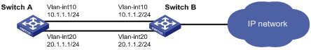
As shown in Figure 1, Switch A has two equal-cost routes to Switch B. Configure load sharing on Switch A to forward packets through Switch B to the destination IP address 1.2.3.4/24.
Configuration procedure
# On Switch A, assign FortyGigE 1/1/5 to VLAN 10, and FortyGigE 1/1/6 to VLAN 20.
<SwitchA> system-view
[SwitchA] vlan 10
[SwitchA-vlan10] port FortyGigE 1/1/5
[SwitchA-vlan10] quit
[SwitchA] vlan 20
[SwitchA-vlan20] port FortyGigE 1/1/6
[SwitchA-vlan20] quit
# On Switch A, configure IP addresses for VLAN-interface 10 and VLAN-interface 20.
[SwitchA] interface vlan-interface 10
[SwitchA-Vlan-interface10] ip address 10.1.1.1 24
[SwitchA-Vlan-interface10] quit
[SwitchA] interface vlan-interface 20
[SwitchA-Vlan-interface20] ip address 20.1.1.1 24
[SwitchA-Vlan-interface20] quit
# On Switch B, assign FortyGigE 1/1/5 to VLAN 10, and FortyGigE 1/1/6 to VLAN 20.
<SwitchB> system-view
[SwitchB] vlan 10
[SwitchB-vlan10] port FortyGigE 1/1/5
[SwitchB-vlan10] quit
[SwitchB] vlan 20
[SwitchB-vlan20] port FortyGigE 1/1/6
[SwitchB-vlan20] quit
# On Switch B, configure IP addresses for VLAN-interface 10 and VLAN-interface 20.
[SwitchB] interface vlan-interface 10
[SwitchB-Vlan-interface10] ip address 10.1.1.2 24
[SwitchB-Vlan-interface10] quit
[SwitchB] interface vlan-interface 20
[SwitchB-Vlan-interface20] ip address 20.1.1.2 24
[SwitchB-Vlan-interface20] quit
# On Switch A, configure two static routes to the destination IP address.
<SwitchA> system-view
[SwitchA] ip route-static 1.2.3.4 24 10.1.1.2
[SwitchA] ip route-static 1.2.3.4 24 20.1.1.2
[SwitchA] quit
# On Switch A, display FIB entries matching the destination IP address 1.2.3.4.
<SwitchA>dis fib 1.2.3.4
Destination count: 1 FIB entry count: 2
Flag:
U:Useable G:Gateway H:Host B:Blackhole D:Dynamic S:Static
R:Relay F:FRR
Destination/Mask Nexthop Flag OutInterface/Token Label
1.2.3.0/24 10.1.1.2 USGR Vlan10 Null
1.2.3.0/24 20.1.1.2 USGR Vlan20 Null
# On Switch A, configure per-flow load sharing based on the source IP address and destination IP address.
<SwitchA> system-view
[SwitchA] ip load-sharing mode per-flow dest-ip src-ip
Verifying the configuration
# Verify that Switch A implements load sharing.
[SwitchA] display counters outbound interface FortyGigE
Interface Total (pkts) Broadcast (pkts) Multicast (pkts) Err (pkts)
FGE1/1/1 0 0 0 0
FGE1/1/2 0 0 0 0
FGE1/1/3 0 0 0 0
FGE1/1/4 0 0 0 0
FGE1/1/5 1045 0 0 0
FGE1/1/6 1044 0 0 0