- Related Documents
-
| Title | Size | Download |
|---|---|---|
| 01-H3C_S7500E_OpenFlow_Configuration_Examples | 1.02 MB |
H3C S7500E OpenFlow Configuration Examples
|
Copyright © 2015 Hangzhou H3C Technologies Co., Ltd. All rights reserved. No part of this manual may be reproduced or transmitted in any form or by any means without prior written consent of Hangzhou H3C Technologies Co., Ltd. The information in this document is subject to change without notice. |
|
Contents
General configuration restrictions and guidelines
Example: Configuring OpenFlow to deploy dynamic flow entries
Example: Example: Configuring OpenFlow to deploy static flow entries
Introduction
This document provides examples for configuring OpenFlow.
OpenFlow separates the control plane and the data forwarding plane. An OpenFlow switch matches packets against one or more flow tables. A flow table contains one or more flow entries deployed by the controller. Packets are matched based on the matching precedence of flow entries.
These examples use VLAN-interface 1.
Prerequisites
The configuration examples in this document were created and verified in a lab environment, and all the devices were started with the factory default configuration. When you are working on a live network, make sure you understand the potential impact of every command on your network.
This document assumes that you have basic knowledge of OpenFlow.
General configuration restrictions and guidelines
When you configure OpenFlow, follow these restrictions and guidelines:
· Enable LLDP globally on OpenFlow switches so that the controller can learn the OpenFlow topology through LLDP.
· Configure each OpenFlow switch with an interface for communicating with the controller so that OpenFlow instances can establish connections with the controller.
· To ensure high availability, use TCP or SSL to establish connections between OpenFlow switches and the controller. This example uses TCP. SSL provides higher availability than TCP.
· For the access ports of switches to belong to an OpenFlow instance, configure the Loosen mode when you associate VLANs 4092 and 4094 with the OpenFlow instance.
Example: Configuring OpenFlow to deploy dynamic flow entries
Network requirements
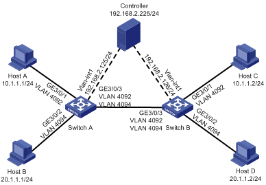
As shown in Figure 1, configure OpenFlow to meet the following requirements:
· The controller can deploy dynamic flow entries.
· Host A and Host C can communicate with each other based on the flow entries deployed by the controller.
· Host B and Host D can communicate with each other based on the flow entries deployed by the controller.
Software version used
This configuration example was created and verified on S7500E-CMW710-R7150.
Configuration procedures
Configuring Switch A
# Create VLAN 4092 and VLAN 4094.
<SwitchA>system-view
[SwitchA]vlan 4092
[SwitchA-vlan4092]quit
[SwitchA]vlan 4094
[SwitchA-vlan4094]quit
# Configure GigabitEthernet 3/0/1, GigabitEthernet 3/0/2, and GigabitEthernet 3/0/3.
[SwitchA]interface GigabitEthernet 3/0/1
[SwitchA-GigabitEthernet3/0/1]port access vlan 4092
[SwitchA-GigabitEthernet3/0/1]quit
[SwitchA]interface GigabitEthernet 3/0/2
[SwitchA-GigabitEthernet3/0/2]port access vlan 4094
[SwitchA-GigabitEthernet3/0/2]quit
[SwitchA]interface GigabitEthernet 3/0/3
[SwitchA-GigabitEthernet3/0/3]port link-type trunk
[SwitchA-GigabitEthernet3/0/3]port trunk permit vlan 4092 4094
[SwitchA-GigabitEthernet3/0/3]quit
# Enable LLDP globally.
[SwitchA] lldp global enable
# Configure VLAN-interface 1 on Switch A for communicating with the controller.
[SwitchA]interface Vlan-interface 1
[SwitchA-Vlan-interface1]ip address 192.168.2.125 255.255.255.0
[SwitchA-Vlan-interface1]quit
# Create OpenFlow instance 1. Associate VLAN 4092 and VLAN 4094 with it in loosen mode.
[SwitchA]openflow instance 1
[SwitchA-of-inst-1]classification vlan 4092 mask 4093 loosen
#Specify controller 0 with IP address 192.168.2.225 for OpenFlow instance 1 and activate the instance..
[SwitchA-of-inst-1]controller 0 address ip 192.168.2.225
[SwitchA-of-inst-1]active instance
[SwitchA-of-inst-1]quit
Configuring Switch B
# Create VLAN 4092 and VLAN 4094.
<SwitchB>system-view
[SwitchB]vlan 4092
[SwitchB-vlan4092]quit
[SwitchB]vlan 4094
[SwitchB-vlan4094]quit
# Configure GigabitEthernet 3/0/1, GigabitEthernet 3/0/2, and GigabitEthernet 3/0/3.
[SwitchB]interface GigabitEthernet 3/0/1
[SwitchB-GigabitEthernet3/0/1]port access vlan 4092
[SwitchB-GigabitEthernet3/0/1]quit
[SwitchB]interface GigabitEthernet 3/0/2
[SwitchB-GigabitEthernet3/0/2]port access vlan 4094
[SwitchB-GigabitEthernet3/0/2]quit
[SwitchB]interface GigabitEthernet 3/0/3
[SwitchB-GigabitEthernet3/0/3]port link-type trunk
[SwitchB-GigabitEthernet3/0/3]port trunk permit vlan 4092 4094
[SwitchB-GigabitEthernet3/0/3]quit
# Enable LLDP globally.
[SwitchB] lldp global enable
# Configure VLAN-interface 1 on Switch B for communicating with the controller.
[SwitchB]interface Vlan-interface 1
[SwitchB-Vlan-interface1]ip address 192.168.2.125 255.255.255.0
[SwitchB-Vlan-interface1]quit
# Create OpenFlow instance 1. Associate VLAN 4092 and VLAN 4094 with it in loosen mode.
[SwitchB]openflow instance 1
[SwitchB-of-inst-1]classification vlan 4092 mask 4093 loosen
#Specify the IP address for controller 0 as 192.168.2.225 for OpenFlow instance 1 and activate the instance.
[SwitchB-of-inst-1]controller 0 address ip 192.168.2.225
[SwitchB-of-inst-1]active instance
[SwitchB-of-inst-1]quit
Verifying the configuration
# Display details for OpenFlow instance 1 on devices, for example, Switch A.
[SwitchA]display openflow instance 1
Instance 1 information:
Configuration information:
Description : --
Active status : Active
Inactive configuration:
None
Active configuration:
Classification VLAN, loosen mode, total VLANs(2)
4092, 4094
In-band management VLAN, total VLANs(0)
Empty VLAN
Connect mode: multiple
MAC address learning: Enabled
Flow table:
Table ID(type): 0(Extensibility), count: 1
Flow-entry max-limit: 8192
Datapath ID: 0x000174258a024c00
Default table-miss: Drop
Forbidden port: None
Port information:
GigabitEthernet3/0/1
GigabitEthernet3/0/2
GigabitEthernet3/0/3
Active channel information:
Controller 0 IP address: 192.168.2.225 port: 6633
The output shows that GigabitEthernet 3/0/1, GigabitEthernet 3/0/2, and GigabitEthernet 3/0/3 belong to OpenFlow instance 1 and can be used to forward packets in the OpenFlow forwarding process.
# Display controller information for OpenFlow instance 1 on devices, for example, Switch A.
<SwitchA>display openflow instance 1 controller
Instance 1 controller information:
Reconnect interval: 60 (s)
Echo interval : 5 (s)
Controller ID : 0
Controller IP address : 192.168.2.225
Controller port : 6633
Controller role : Equal
Connect type : TCP
Connect state : Established
Packets sent : 132
Packets received : 434
SSL policy : --
VRF name : --
The output shows that Switch A has established a connection with the controller.
# Display flow table information for OpenFlow instance 1 on devices, for example, Switch A.
<SwitchA>display openflow instance 1 flow-table
Instance 1 flow table information:
Table 0 information:
Table type: Extensibility, flow entry count: 1, total flow entry count: 1
MissRule (default) flow entry information:
cookie: 0x0, priority: 0, hard time: 0, idle time: 0, flags: flow_send_rem,
byte count: --, packet count: 0
Match information: any
Instruction information:
Write actions:
Output interface: Controller, send length: 65509 bytes
The output shows that Switch A has only one table-miss flow entry with the priority of 0 and the action of outputting packets to the controller.
# Ping Host C from Host A.
Ping 10.1.1.2 (10.1.1.2): 56 data bytes, press CTRL_C to break
56 bytes from 10.1.1.2: icmp_seq=0 ttl=255 time=4.582 ms
56 bytes from 10.1.1.2: icmp_seq=1 ttl=255 time=1.299 ms
56 bytes from 10.1.1.2: icmp_seq=2 ttl=255 time=1.389 ms
56 bytes from 10.1.1.2: icmp_seq=3 ttl=255 time=6.688 ms
56 bytes from 10.1.1.2: icmp_seq=4 ttl=255 time=1.294 ms
--- Ping statistics for 10.1.1.2 ---
5 packet(s) transmitted, 5 packet(s) received, 0.0% packet loss
round-trip min/avg/max/std-dev = 1.294/3.050/6.688/2.213 ms
The output shows that Host A and Host C can reach each other.
# Display flow table information for OpenFlow instance 1 again on devices, for example, Switch A.
<SwitchA>display openflow instance 1 flow-table
Instance 1 flow table information:
Table 0 information:
Table type: Extensibility, flow entry count: 4, total flow entry count: 4
MissRule (default) flow entry information:
cookie: 0x0, priority: 0, hard time: 0, idle time: 0, flags: flow_send_rem,
byte count: --, packet count: 0
Match information: any
Instruction information:
Write actions:
Output interface: Controller, send length: 65509 bytes
Flow entry 1 information:
cookie: 0x2328, priority: 29999, hard time: 0, idle time: 300, flags:
flow_send_rem, byte count: --, packet count: 1
Match information:
Input interface: GE3/0/3
Ethernet destination MAC address: 0cda-41b1-d1c5
Ethernet destination MAC address mask: ffff-ffff-ffff
Ethernet source MAC address: 7425-8a0f-8034
Ethernet source MAC address mask: ffff-ffff-ffff
Ethernet type: 0x0806
Instruction information:
Write actions:
Output interface: GE3/0/1
Flow entry 2 information:
cookie: 0x2328, priority: 29999, hard time: 0, idle time: 300, flags:
flow_send_rem, byte count: --, packet count: 4
Match information:
Input interface: GE3/0/1
Ethernet destination MAC address: 7425-8a0f-8034
Ethernet destination MAC address mask: ffff-ffff-ffff
Ethernet source MAC address: 0cda-41b1-d1c5
Ethernet source MAC address mask: ffff-ffff-ffff
Ethernet type: 0x0800
Instruction information:
Write actions:
Output interface: GE3/0/3
Flow entry 3 information:
cookie: 0x2328, priority: 29999, hard time: 0, idle time: 300, flags:
flow_send_rem, byte count: --, packet count: 4
Match information:
Input interface: GE3/0/3
Ethernet destination MAC address: 0cda-41b1-d1c5
Ethernet destination MAC address mask: ffff-ffff-ffff
Ethernet source MAC address: 7425-8a0f-8034
Ethernet source MAC address mask: ffff-ffff-ffff
Ethernet type: 0x0800
Instruction information:
Write actions:
Output interface: GE3/0/1
The output shows the following information:
· The ARP request/reply packets and ICMP request/replay packets between Host A and Host C successfully trigger the controller to deploy flow entries.
· Switch A forwards packets based on the flow entries that are deployed by the controller.
# Ping Host D from Host B.
Ping 20.1.1.2 (20.1.1.2): 56 data bytes, press CTRL_C to break
56 bytes from 20.1.1.2: icmp_seq=0 ttl=255 time=1.620 ms
56 bytes from 20.1.1.2: icmp_seq=1 ttl=255 time=6.625 ms
56 bytes from 20.1.1.2: icmp_seq=2 ttl=255 time=1.454 ms
56 bytes from 20.1.1.2: icmp_seq=3 ttl=255 time=1.134 ms
56 bytes from 20.1.1.2: icmp_seq=4 ttl=255 time=1.260 ms
--- Ping statistics for 20.1.1.2 ---
5 packet(s) transmitted, 5 packet(s) received, 0.0% packet loss
round-trip min/avg/max/std-dev = 1.134/2.419/6.625/2.110 ms
The output shows that Host B and Host D can reach each other.
# Display flow table information for OpenFlow instance 1 again on devices, for example, Switch A.
<SwitchA>display openflow instance 1 flow-table
Instance 1 flow table information:
Table 0 information:
Table type: Extensibility, flow entry count: 7, total flow entry count: 7
MissRule (default) flow entry information:
cookie: 0x0, priority: 0, hard time: 0, idle time: 0, flags: flow_send_rem,
byte count: --, packet count: 0
Match information: any
Instruction information:
Write actions:
Output interface: Controller, send length: 65509 bytes
Flow entry 1 information:
cookie: 0x2328, priority: 29999, hard time: 0, idle time: 300, flags:
flow_send_rem, byte count: --, packet count: 1
Match information:
Input interface: GE3/0/3
Ethernet destination MAC address: 0cda-41b1-d1c5
Ethernet destination MAC address mask: ffff-ffff-ffff
Ethernet source MAC address: 7425-8a0f-8034
Ethernet source MAC address mask: ffff-ffff-ffff
Ethernet type: 0x0806
Instruction information:
Write actions:
Output interface: GE3/0/1
Flow entry 2 information:
cookie: 0x2328, priority: 29999, hard time: 0, idle time: 300, flags:
flow_send_rem, byte count: --, packet count: 4
Match information:
Input interface: GE3/0/1
Ethernet destination MAC address: 7425-8a0f-8034
Ethernet destination MAC address mask: ffff-ffff-ffff
Ethernet source MAC address: 0cda-41b1-d1c5
Ethernet source MAC address mask: ffff-ffff-ffff
Ethernet type: 0x0800
Instruction information:
Write actions:
Output interface: GE3/0/3
Flow entry 3 information:
cookie: 0x2328, priority: 29999, hard time: 0, idle time: 300, flags:
flow_send_rem, byte count: --, packet count: 4
Match information:
Input interface: GE3/0/3
Ethernet destination MAC address: 0cda-41b1-d1c5
Ethernet destination MAC address mask: ffff-ffff-ffff
Ethernet source MAC address: 7425-8a0f-8034
Ethernet source MAC address mask: ffff-ffff-ffff
Ethernet type: 0x0800
Instruction information:
Write actions:
Output interface: GE3/0/1
Flow entry 4 information:
cookie: 0x2328, priority: 29999, hard time: 0, idle time: 300, flags:
flow_send_rem, byte count: --, packet count: 1
Match information:
Input interface: GE3/0/3
Ethernet destination MAC address: 0cda-41b1-d1c4
Ethernet destination MAC address mask: ffff-ffff-ffff
Ethernet source MAC address: 7425-8a0f-8035
Ethernet source MAC address mask: ffff-ffff-ffff
Ethernet type: 0x0806
Instruction information:
Write actions:
Output interface: GE3/0/2
Flow entry 5 information:
cookie: 0x2328, priority: 29999, hard time: 0, idle time: 300, flags:
flow_send_rem, byte count: --, packet count: 4
Match information:
Input interface: GE3/0/2
Ethernet destination MAC address: 7425-8a0f-8035
Ethernet destination MAC address mask: ffff-ffff-ffff
Ethernet source MAC address: 0cda-41b1-d1c4
Ethernet source MAC address mask: ffff-ffff-ffff
Ethernet type: 0x0800
Instruction information:
Write actions:
Output interface: GE3/0/3
Flow entry 6 information:
cookie: 0x2328, priority: 29999, hard time: 0, idle time: 300, flags:
flow_send_rem, byte count: --, packet count: 4
Match information:
Input interface: GE3/0/3
Ethernet destination MAC address: 0cda-41b1-d1c4
Ethernet destination MAC address mask: ffff-ffff-ffff
Ethernet source MAC address: 7425-8a0f-8035
Ethernet source MAC address mask: ffff-ffff-ffff
Ethernet type: 0x0800
Instruction information:
Write actions:
Output interface: GE3/0/2
The output shows the following information:
· The ARP request/reply packets and ICMP request/replay packets between Host B and Host D successfully trigger the controller to deploy flow entries.
· Switch A forwards packets based on the flow entries that are deployed by the controller.
Configuration files
· Switch A:
#
lldp global enable
#
openflow instance 1
classification vlan 4092 mask 4093 loosen
controller 0 address ip 192.168.2.225
#
interface Vlan-interface1
ip address 192.168.2.125 255.255.255.0
#
interface GigabitEthernet3/0/1
port link-mode bridge
port access vlan 4092
#
interface GigabitEthernet3/0/2
port link-mode bridge
port access vlan 4094
#
interface GigabitEthernet3/0/3
port link-mode bridge
port link-type trunk
port trunk permit vlan 1 4092 4094
#
· Switch B:
#
lldp global enable
#
openflow instance 1
classification vlan 4092 mask 4093 loosen
controller 0 address ip 192.168.2.225
#
interface Vlan-interface1
ip address 192.168.2.126 255.255.255.0
#
interface GigabitEthernet3/0/1
port link-mode bridge
port access vlan 4092
#
interface GigabitEthernet3/0/2
port link-mode bridge
port access vlan 4094
#
interface GigabitEthernet3/0/3
port link-mode bridge
port link-type trunk
port trunk permit vlan 1 4092 4094
#
Example: Example: Configuring OpenFlow to deploy static flow entries
Network requirements
As shown in Figure 2, configure OpenFlow to meet the following requirements:
· The controller deploys static flow entries.
· Host A and Host C can communicate with each other based on the flow entries deployed by the controller.
· Host B and Host D can communicate with each other based on the flow entries deployed by the controller.
Software version used
This configuration example was created and verified on S7500E-CMW710-R7150.
Configuration procedures
Configuring Switch A
# Create VLAN 4092 and VLAN 4094.
<SwitchA>system-view
[SwitchA]vlan 4092
[SwitchA-vlan4092]quit
[SwitchA]vlan 4094
[SwitchA-vlan4094]quit
# Configure GigabitEthernet 3/0/1, GigabitEthernet 3/0/2, and GigabitEthernet 3/0/3.
[SwitchA]interface GigabitEthernet 3/0/1
[SwitchA-GigabitEthernet3/0/1]port access vlan 4092
[SwitchA-GigabitEthernet3/0/1]quit
[SwitchA]interface GigabitEthernet 3/0/2
[SwitchA-GigabitEthernet3/0/2]port access vlan 4094
[SwitchA-GigabitEthernet3/0/2]quit
[SwitchA]interface GigabitEthernet 3/0/3
[SwitchA-GigabitEthernet3/0/3]port link-type trunk
[SwitchA-GigabitEthernet3/0/3]port trunk permit vlan 4092 4094
[SwitchA-GigabitEthernet3/0/3]quit
# Enable LLDP globally.
[SwitchA] lldp global enable
# Configure VLAN-interface 1 on Switch A for communicating with the controller.
[SwitchA]interface Vlan-interface 1
[SwitchA-Vlan-interface1]ip address 192.168.2.125 255.255.255.0
[SwitchA-Vlan-interface1]quit
# Create OpenFlow instance 1. Associate VLAN 4092 and VLAN 4094 with it in loosen mode.
[SwitchA]openflow instance 1
[SwitchA-of-inst-1]classification vlan 4092 mask 4093 loosen
# Specify controller 0 with IP address 192.168.2.225 for OpenFlow instance 1 and activate the instance.
[SwitchA-of-inst-1]controller 0 address ip 192.168.2.225
[SwitchA-of-inst-1]active instance
[SwitchA-of-inst-1]quit
Configuring Switch B
# Create VLAN 4092 and VLAN 4094.
<SwitchB>system-view
[SwitchB]vlan 4092
[SwitchB-vlan4092]quit
[SwitchB]vlan 4094
[SwitchB-vlan4094]quit
# Configure GigabitEthernet 3/0/1, GigabitEthernet 3/0/2, and GigabitEthernet 3/0/3.
[SwitchB]interface GigabitEthernet 3/0/1
[SwitchB-GigabitEthernet3/0/1]port access vlan 4092
[SwitchB-GigabitEthernet3/0/1]quit
[SwitchB]interface GigabitEthernet 3/0/2
[SwitchB-GigabitEthernet3/0/2]port access vlan 4094
[SwitchB-GigabitEthernet3/0/2]quit
[SwitchB]interface GigabitEthernet 3/0/3
[SwitchB-GigabitEthernet3/0/3]port link-type trunk
[SwitchB-GigabitEthernet3/0/3]port trunk permit vlan 4092 4094
[SwitchB-GigabitEthernet3/0/3]quit
# Enable LLDP globally.
[SwitchB] lldp global enable
# Configure VLAN-interface 1 on Switch B for communicating with the controller.
[SwitchB]interface Vlan-interface 1
[SwitchB-Vlan-interface1]ip address 192.168.2.125 255.255.255.0
[SwitchB-Vlan-interface1]quit
# Create OpenFlow instance 1. Associate VLAN 4092 and VLAN 4094 with it in loosen mode.
[SwitchB]openflow instance 1
[SwitchB-of-inst-1]classification vlan 4092 mask 4093 loosen
#Specify the IP address for controller 0 as 192.168.2.225 for OpenFlow instance 1 and activate the instance.
[SwitchB-of-inst-1]controller 0 address ip 192.168.2.225
[SwitchB-of-inst-1]active instance
[SwitchB-of-inst-1]quit
Configuring the controller
Obtaining the DPID and port numbers for OpenFlow instances by logging in to the VCF controller through GUI
The VCF controller uses the following parameters to deploy flow entries:
· DPID—Uniquely identifies an OpenFlow instance.
· Port number—Uniquely identifies a physical interface (for example, a Layer 2 Ethernet interface) or a logical interface (for example, a Layer 2 aggregate interface). The controller can identify a physical interface (for example, GigabitEthernet3/0/3) or a logical interface only through a port number (for example, 159) when deploying flow entries.
To obtain the DPID and port numbers for OpenFlow instance 1:
1. Launch the browser.
2. In the address bar, type the login address in the format https://controller_ip_address:8443/sdn/ui/.
This example uses https://192.168.2.225:8443/sdn/ui/.
The controller_ip_address is the IP address of the server or virtual machine on which your controller is installed. The value of 8443 is the default port number.
3. Press Enter.
The H3C VCF Controller Login page appears, as shown in Figure 3.
Figure 3 H3C VCF Controller Login page
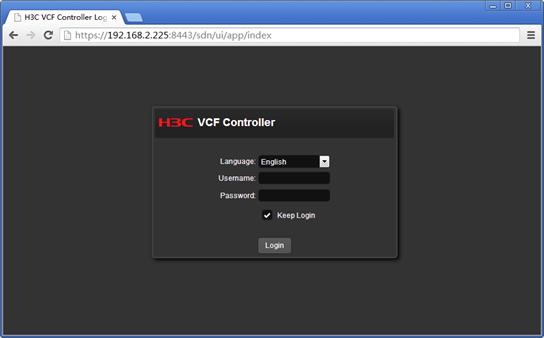
4. On the H3C VCF Controller Login page, select a language from the Language list.
5. Enter the username and password, and click Login. By default, the username is sdn and the password is skyline.
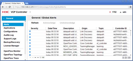
The H3C VCF Controller page appears, as shown in Figure 4.
Figure 4 H3C VCF Controller page
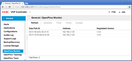
6. From the navigation tree, select OpenFlow Monitor.
The General/OpenFlow Monitor page appears, as shown in Figure 5.
Figure 5 Obtaining the DPIDs for OpenFlow instances
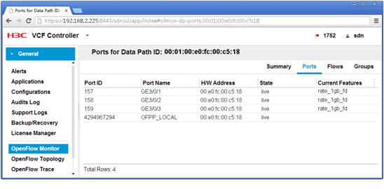
7. Click the datapath ID for the OpenFlow instance on Switch A, and click Port, as shown in Figure 6.
The Port page appears, as shown in Figure 7.
Figure 6 Clicking the datapath ID for the OpenFlow instance on Switch A
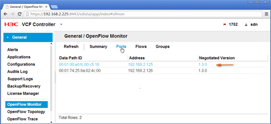
Figure 7 Obtaining port information for the OpenFlow instance on Switch A
8. Obtain the port information for the OpenFlow instance on Switch B in the same way the port information for the OpenFlow instance on Switch A is obtained.
Authenticating the user name and password by logging in to the VCF controller through RSdoc
You can configure the controller to deploy flow entries only after you pass authentication on the RSdoc page. You must authenticate the user name and password each time you log in to the RSdoc page.
To authenticate the user information:
1. Launch the browser.
2. In the address bar, type the login address in the format: https://controller_ip_address:8443/api/.
This example uses https://192.168.221.221:8443/api/.
The controller_ip_address refers to the IP address of the server or virtual machine on which your controller is installed. The value of 8443 is the default port number.
3. Press Enter.
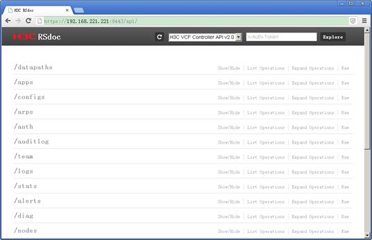
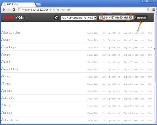
The H3C RSdoc page appears, as shown in Figure 8.
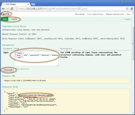
4. Obtain the token for RSdoc authentication, as shown in Figure 9:
a. Click /auth to expand the /auth area.
b. In the Login field, enter {"login":{"user":"username","password":"password","domain":"sdn"}}.
By default, the username is sdn and the password is skyline.
c. Click Try it out.
The token appears in the Response Body area (see Figure 9).
Figure 9 Obtaining the token for RSdoc authentication
5. Copy and paste the token to the X-Auth-Token field in the upper right corner of the H3C RSdoc page, and click Explore, as shown in Figure 10.
If the token is valid, further requests from RSdoc to the controller will be successfully authenticated.
Figure 10 RSdoc authentication
Deploying flow entries
1. On the H3C RSdoc page, click /datapaths to expand the /datapaths area, as shown in Figure 11.
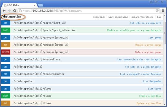
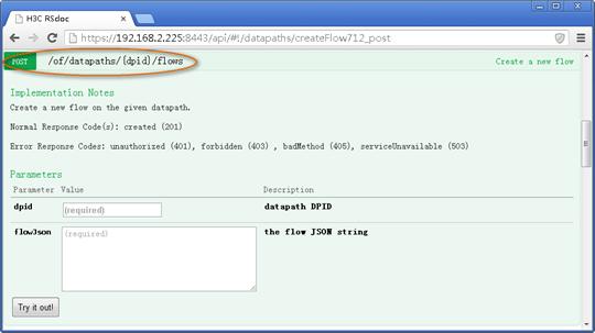
2. Click POST /of/datapaths/(dpid)/flows to expand the POST /of/datapaths/(dpid)/flows area, as shown in Figure 12.
Figure 12 POST /of/datapaths/(dpid)/flows area
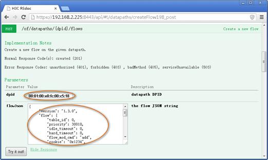
3. Deploy flow entries, as shown in Table 1Figure 13.
a. In the dpid filed, enter the datapath ID you have obtained.
This example uses 00:01:00:e0:fc:00:c5:18.
b. In the flowJson field, enter the following information to configure a flow entry to be deployed:
{
"version": "1.3.0",
"flow": {
"table_id": 0,
"priority": 30010,
"idle_timeout": 0,
"hard_timeout": 0,
"flow_mod_cmd": "add",
"cookie": "0x1234",
"cookie_mask": "0xffff",
"out_port": 159,
"flow_mod_flags": [
"send_flow_rem"
],
"match": [
{"in_port": "157"},
{"vlan_vid": "4092" } ] ,
"instructions": [
{
"write_actions": [
{
"output":159
}
]
}
]
}
}
|
|
NOTE: If the priority and match fields in the flowJson area are the same as those of an existing flow entry, the controller only updates the other parameters of the entry. The controller will not create a new flow entry. |
Table 1 Fields of flowJson flow entry
|
Field |
Description |
|
version |
OpenFlow protocol version. |
|
Table_id |
ID of the flow table. |
|
priority |
Priority of the flow entry. The larger the value, the higher the priority. |
|
idle_timeout |
Idle timeout of the flow entry, in seconds. The value of 0 indicates that the flow entry never times out. The flow entry is removed if the flow entry does not match any data streams during the idle time. |
|
hard_timeout |
Hard timeout of the flow entry, in seconds. The value of 0 indicates that the flow entry never times out. The flow entry is removed when the timer times out, whether or not the flow entry matches any data streams. |
|
flow_mod_cmd |
Flow table modification message type: · add—Adds new flow entries or modifies the existing flow entries. · modify—Modifies the instructions of flow entries. · modify_strict—Modifies the instructions of flow entries strictly. In the strict version, all match fields are strictly matched against an entry. Only an identical flow entry is modified. · delete—Deletes flow entries. · delete_strict—Deletes flow entries strictly. In the strict version, all match fields are strictly matched against an entry. Only an identical flow entry is deleted. |
|
cookie |
Cookie ID of the flow entry. |
|
cookie_mask |
Cookie mask of the flow entry. The cookie value is calculated by a bitwise AND operation on the specified cookie and mask. |
|
out_port |
Output port of packets. When you delete a flow entry, the flow entry must be uniquely identified by the combination of out_port, cookie, and match fields. |
|
flags |
Flags that the flow entry includes: · send_flow_rem—Sends a flow removed message when the flow entry is removed or expires. · no_paket_counts—Does not count packets. · no_byte_counts—Does not count bytes. · none—Does not include any flags. |
|
match |
Contents of the match fields of the flow entry: · In_port—Match packets from the specified input ports. For more information about obtaining port numbers, see "Obtaining the DPID and port numbers for OpenFlow instances by logging in to the VCF controller through GUI." · vlan_vid—Match packets from the specified VLANs. A flow entry matches a packet only when all match fields of the flow entry match the fields of the packet. |
|
Instruction |
Contents of the instruction set of the flow entry: · Set meter—Sends the matched packet to the specified meter. · Write actions—Writes the specified actions into the current action set. · Clear actions—Immediately clears all actions in the action set. · Apply actions—Immediately applies the specified actions in the action set. |
|
Output |
Send packets out the specified ports. For more information about obtaining port numbers, see "Obtaining the DPID and port numbers for OpenFlow instances by logging in to the VCF controller through GUI." |
Figure 13 Configuring flow entries
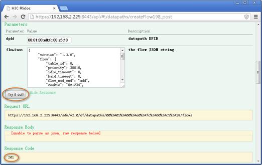
c. Click Try it out, as shown in Figure 14.
The value of the three-digital number that starts with 2 in the Response Code area indicates that the flow entry has been successfully deployed.
Figure 14 Deploying flow entries
4. Verify whether the flow entry has been successfully deployed by performing the follow tasks:
? View whether devices (for example, Switch A) print the following information:
%Jun 28 11:55:05:227 2024 SwitchA OFP/5/OFP_FLOW_ADD: -MDC=1; Openflow instance
1 controller 0: add flow entry 1, xid 0x79, cookie 0x1234, table id 0.
? View flow table information for OpenFlow instance 1 on devices, for example, Switch A.
<SwitchA>display openflow instance 1 flow-table
Instance 1 flow table information:
Table 0 information:
Table type: Extensibility, flow entry count: 2, total flow entry count: 2
MissRule (default) flow entry information:
cookie: 0x0, priority: 0, hard time: 0, idle time: 0, flags: flow_send_rem,
byte count: --, packet count: 0
Match information: any
Instruction information:
Write actions:
Output interface: Controller, send length: 65509 bytes
Flow entry 1 information:
cookie: 0x1234, priority: 30010, hard time: 0, idle time: 0, flags:
flow_send_rem, byte count: --, packet count: 0
Match information:
Input interface: GE3/0/1
VLAN ID: 4092, mask: 0xfff
Instruction information:
Write actions:
Output interface: GE3/0/3
The output shows that the flow entry has been successfully deployed.
5. Deploy the other flow entries in the same way the first flow entry is deployed.
Verifying the configuration
# Display flow table information for OpenFlow instance 1 on devices, for example, Switch A.
<SwitchA>display openflow instance 1 flow-table
Instance 1 flow table information:
Table 0 information:
Table type: Extensibility, flow entry count: 5, total flow entry count: 5
MissRule (default) flow entry information:
cookie: 0x0, priority: 0, hard time: 0, idle time: 0, flags: flow_send_rem,
byte count: --, packet count: 0
Match information: any
Instruction information:
Write actions:
Output interface: Controller, send length: 65509 bytes
Flow entry 1 information:
cookie: 0x1234, priority: 30010, hard time: 0, idle time: 0, flags:
flow_send_rem, byte count: --, packet count: 0
Match information:
Input interface: GE3/0/1
VLAN ID: 4092, mask: 0xfff
Instruction information:
Write actions:
Output interface: GE3/0/3
Flow entry 2 information:
cookie: 0x1234, priority: 30010, hard time: 0, idle time: 0, flags:
flow_send_rem, byte count: --, packet count: 0
Match information:
Input interface: GE3/0/3
VLAN ID: 4092, mask: 0xfff
Instruction information:
Write actions:
Output interface: GE3/0/1
Flow entry 3 information:
cookie: 0x1234, priority: 30010, hard time: 0, idle time: 0, flags:
flow_send_rem, byte count: --, packet count: 0
Match information:
Input interface: GE3/0/2
VLAN ID: 4094, mask: 0xfff
Instruction information:
Write actions:
Output interface: GE3/0/3
Flow entry 4 information:
cookie: 0x1234, priority: 30010, hard time: 0, idle time: 0, flags:
flow_send_rem, byte count: --, packet count: 0
Match information:
Input interface: GE3/0/3
VLAN ID: 4094, mask: 0xfff
Instruction information:
Write actions:
Output interface: GE3/0/2
# Ping Host C from Host A.
Ping 10.1.1.2 (10.1.1.2): 56 data bytes, press CTRL_C to break
56 bytes from 10.1.1.2: icmp_seq=0 ttl=255 time=4.582 ms
56 bytes from 10.1.1.2: icmp_seq=1 ttl=255 time=1.299 ms
56 bytes from 10.1.1.2: icmp_seq=2 ttl=255 time=1.389 ms
56 bytes from 10.1.1.2: icmp_seq=3 ttl=255 time=6.688 ms
56 bytes from 10.1.1.2: icmp_seq=4 ttl=255 time=1.294 ms
--- Ping statistics for 10.1.1.2 ---
5 packet(s) transmitted, 5 packet(s) received, 0.0% packet loss
round-trip min/avg/max/std-dev = 1.294/3.050/6.688/2.213 ms
The output shows that Host A and Host C can reach each other.
# Display flow table information for OpenFlow instance 1 again on devices, for example, Switch A.
<SwitchA>display openflow instance 1 flow-table
Instance 1 flow table information:
Table 0 information:
Table type: Extensibility, flow entry count: 5, total flow entry count: 5
MissRule (default) flow entry information:
cookie: 0x0, priority: 0, hard time: 0, idle time: 0, flags: flow_send_rem,
byte count: --, packet count: 0
Match information: any
Instruction information:
Write actions:
Output interface: Controller, send length: 65509 bytes
Flow entry 1 information:
cookie: 0x1234, priority: 30010, hard time: 0, idle time: 0, flags:
flow_send_rem, byte count: --, packet count: 6
Match information:
Input interface: GE3/0/1
VLAN ID: 4092, mask: 0xfff
Instruction information:
Write actions:
Output interface: GE3/0/3
Flow entry 2 information:
cookie: 0x1234, priority: 30010, hard time: 0, idle time: 0, flags:
flow_send_rem, byte count: --, packet count: 6
Match information:
Input interface: GE3/0/3
VLAN ID: 4092, mask: 0xfff
Instruction information:
Write actions:
Output interface: GE3/0/1
Flow entry 3 information:
cookie: 0x1234, priority: 30010, hard time: 0, idle time: 0, flags:
flow_send_rem, byte count: --, packet count: 0
Match information:
Input interface: GE3/0/2
VLAN ID: 4094, mask: 0xfff
Instruction information:
Write actions:
Output interface: GE3/0/3
Flow entry 4 information:
cookie: 0x1234, priority: 30010, hard time: 0, idle time: 0, flags:
flow_send_rem, byte count: --, packet count: 0
Match information:
Input interface: GE3/0/3
VLAN ID: 4094, mask: 0xfff
Instruction information:
Write actions:
Output interface: GE3/0/2
The output shows that the packets between Host A and Host C are forwarded based on flow entry 1 and flow entry 2.
# Ping Host D from Host B.
Ping 20.1.1.2 (20.1.1.2): 56 data bytes, press CTRL_C to break
56 bytes from 20.1.1.2: icmp_seq=0 ttl=255 time=1.620 ms
56 bytes from 20.1.1.2: icmp_seq=1 ttl=255 time=6.625 ms
56 bytes from 20.1.1.2: icmp_seq=2 ttl=255 time=1.454 ms
56 bytes from 20.1.1.2: icmp_seq=3 ttl=255 time=1.134 ms
56 bytes from 20.1.1.2: icmp_seq=4 ttl=255 time=1.260 ms
--- Ping statistics for 20.1.1.2 ---
5 packet(s) transmitted, 5 packet(s) received, 0.0% packet loss
round-trip min/avg/max/std-dev = 1.134/2.419/6.625/2.110 ms
The output shows that Host B and Host D can reach each other.
# Display flow table information for OpenFlow instance 1 again on devices, for example, Switch A.
<SwitchA>display openflow instance 1 flow-table
Instance 1 flow table information:
Table 0 information:
Table type: Extensibility, flow entry count: 5, total flow entry count: 5
MissRule (default) flow entry information:
cookie: 0x0, priority: 0, hard time: 0, idle time: 0, flags: flow_send_rem,
byte count: --, packet count: 0
Match information: any
Instruction information:
Write actions:
Output interface: Controller, send length: 65509 bytes
Flow entry 1 information:
cookie: 0x1234, priority: 30010, hard time: 0, idle time: 0, flags:
flow_send_rem, byte count: --, packet count: 6
Match information:
Input interface: GE3/0/1
VLAN ID: 4092, mask: 0xfff
Instruction information:
Write actions:
Output interface: GE3/0/3
Flow entry 2 information:
cookie: 0x1234, priority: 30010, hard time: 0, idle time: 0, flags:
flow_send_rem, byte count: --, packet count: 6
Match information:
Input interface: GE3/0/3
VLAN ID: 4092, mask: 0xfff
Instruction information:
Write actions:
Output interface: GE3/0/1
Flow entry 3 information:
cookie: 0x1234, priority: 30010, hard time: 0, idle time: 0, flags:
flow_send_rem, byte count: --, packet count: 6
Match information:
Input interface: GE3/0/2
VLAN ID: 4094, mask: 0xfff
Instruction information:
Write actions:
Output interface: GE3/0/3
Flow entry 4 information:
cookie: 0x1234, priority: 30010, hard time: 0, idle time: 0, flags:
flow_send_rem, byte count: --, packet count: 6
Match information:
Input interface: GE3/0/3
VLAN ID: 4094, mask: 0xfff
Instruction information:
Write actions:
Output interface: GE3/0/2
The output shows that the packets between Host B and Host D are forwarded based on flow entry 3 and flow entry 4.
Configuration files
· Switch A:
#
lldp global enable
#
openflow instance 1
classification vlan 4092 mask 4093 loosen
controller 0 address ip 192.168.2.225
#
interface Vlan-interface1
ip address 192.168.2.125 255.255.255.0
#
interface GigabitEthernet3/0/1
port link-mode bridge
port access vlan 4092
#
interface GigabitEthernet3/0/2
port link-mode bridge
port access vlan 4094
#
interface GigabitEthernet3/0/3
port link-mode bridge
port link-type trunk
port trunk permit vlan 1 4092 4094
#
· Switch B:
#
lldp global enable
#
openflow instance 1
classification vlan 4092 mask 4093 loosen
controller 0 address ip 192.168.2.225
#
interface Vlan-interface1
ip address 192.168.2.126 255.255.255.0
#
interface GigabitEthernet3/0/1
port link-mode bridge
port access vlan 4092
#
interface GigabitEthernet3/0/2
port link-mode bridge
port access vlan 4094
#
interface GigabitEthernet3/0/3
port link-mode bridge
port link-type trunk
port trunk permit vlan 1 4092 4094
#
Related documentation
· H3C S7500E Switch Series OpenFlow Configuration Guide-Release 7150
· H3C S7500E Switch Series OpenFlow Command Reference-Release 7150