- Table of Contents
-
- 03-Layer 2 - LAN Switching Configuration Examples
- 01-H3C_S7500E_MAC_Address_Table_Configuration_Examples
- 02-H3C_S7500E_Ethernet_Link_Aggregation_Configuration_Examples
- 03-H3C_S7500E_Port_Isolation_Configuration_Examples
- 04-H3C_S7500E_Spanning_Tree_Configuration_Examples
- 05-H3C_S7500E_VLAN_Configuration_Examples
- 06-H3C_S7500E_MVRP_Configuration_Examples
- 07-H3C_S7500E_QinQ_Configuration_Examples
- 08-H3C_S7500E_VLAN_Mapping_Configuration_Examples
- Related Documents
-
| Title | Size | Download |
|---|---|---|
| 03-H3C_S7500E_Port_Isolation_Configuration_Examples | 107.2 KB |
H3C S7500E Port Isolation Configuration Examples
|
Copyright © 2015 Hangzhou H3C Technologies Co., Ltd. All rights reserved. No part of this manual may be reproduced or transmitted in any form or by any means without prior written consent of Hangzhou H3C Technologies Co., Ltd. The information in this document is subject to change without notice. |
|
Introduction
This document provides port isolation configuration examples.
Prerequisites
This document is not restricted to specific software or hardware versions.
The configuration examples in this document were created and verified in a lab environment, and all the devices were started with the factory default configuration. When you are working on a live network, make sure you understand the potential impact of every command on your network.
This document assumes that you have basic knowledge of port isolation.
Example: Configuring port isolation
Network requirements
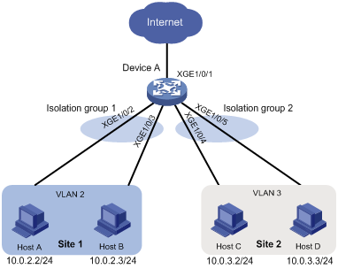
As shown in Figure 1, the company branches Site 1 and Site 2 transfer service traffic in VLAN 2 and VLAN 3. Device A connects to the Internet through Ten-GigabitEthernet 1/0/1.
Configure port isolation on Device A to meet the following requirements:
· All hosts can access the Internet through Device A.
· Host A and Host B are isolated from each other at Layer 2.
· Host C and Host D are isolated from each other at Layer 2.
Software version used
This configuration example was created and verified on S7500E-CMW710-R7150.
Configuration restrictions and guidelines
When you configure port isolation on the device, follow these restrictions and guidelines:
· Before assigning a port to an isolation group, make sure the isolation group already exists.
· You can assign a port to only one isolation group.
Configuration procedure
# Create VLAN 2 and assign ports Ten-GigabitEthernet 1/0/2 and Ten-GigabitEthernet 1/0/3 to the VLAN.
<DeviceA> system-view
[DeviceA] vlan 2
[DeviceA-vlan2] port ten-gigabitethernet 1/0/2
[DeviceA-vlan2] port ten-gigabitethernet 1/0/3
[DeviceA-vlan2] quit
# Create VLAN 3 and assign ports Ten-GigabitEthernet 1/0/4 and Ten-GigabitEthernet 1/0/5 to the VLAN.
[DeviceA] vlan 3
[DeviceA-vlan3] port ten-gigabitethernet 1/0/4
[DeviceA-vlan3] port ten-gigabitethernet 1/0/5
[DeviceA-vlan3] quit
# Configure port Ten-GigabitEthernet 1/0/1 as a trunk port and assign it to VLAN 2 and VLAN 3.
[DeviceA] interface ten-gigabitethernet 1/0/1
[DeviceA-Ten-GigabitEthernet1/0/1] port link-type trunk
[DeviceA-Ten-GigabitEthernet1/0/1] port trunk permit vlan 2 3
[DeviceA-Ten-GigabitEthernet1/0/1] quit
# Create isolation groups 1 and 2.
[DeviceA] port-isolate group 1
[DeviceA-port-isolate-group1] quit
[DeviceA] port-isolate group 2
[DeviceA-port-isolate-group2] quit
# Assign ports Ten-GigabitEthernet 1/0/2 and Ten-GigabitEthernet 1/0/3 to isolation group 1.
[DeviceA] interface ten-gigabitethernet 1/0/2
[DeviceA-Ten-GigabitEthernet1/0/2] port-isolate enable group 1
[DeviceA-Ten-GigabitEthernet1/0/2] quit
[DeviceA] interface ten-gigabitethernet 1/0/3
[DeviceA-Ten-GigabitEthernet1/0/3] port-isolate enable group 1
[DeviceA-Ten-GigabitEthernet1/0/3] quit
# Assign ports Ten-GigabitEthernet 1/0/4 and Ten-GigabitEthernet 1/0/5 to isolation group 2.
[DeviceA] interface ten-gigabitethernet 1/0/4
[DeviceA-Ten-GigabitEthernet1/0/4] port-isolate enable group 2
[DeviceA-Ten-GigabitEthernet1/0/4] quit
[DeviceA] interface ten-gigabitethernet 1/0/5
[DeviceA-Ten-GigabitEthernet1/0/5] port-isolate enable group 2
[DeviceA-Ten-GigabitEthernet1/0/5] quit
Verifying the configuration
# Display information about all isolation groups.
[DeviceA] display port-isolate group
Port isolation group information:
Group ID: 1
Group members:
Ten-GigabitEthernet1/0/2
Ten-GigabitEthernet1/0/3
Group ID: 2
Group members:
Ten-GigabitEthernet1/0/4
Ten-GigabitEthernet1/0/5
The output shows that:
· Ports Ten-GigabitEthernet 1/0/2 and Ten-GigabitEthernet 1/0/3 are in isolation group 1. As a result, Host A and Host B are isolated from each other at Layer 2.
· Ports Ten-GigabitEthernet 1/0/4 and Ten-GigabitEthernet 1/0/4 are in isolation group 2. As a result, Host C and Host D are isolated from each other at Layer 2.
Configuration files
port-isolate group 1
port-isolate group 2
#
vlan 2 to 3
#
interface Ten-GigabitEthernet1/0/1
port link-mode bridge
port link-type trunk
port trunk permit vlan 1 to 3
#
interface Ten-GigabitEthernet1/0/2
port link-mode bridge
port access vlan 2
port-isolate enable group 1
#
interface Ten-GigabitEthernet1/0/3
port link-mode bridge
port access vlan 2
port-isolate enable group 1
#
interface Ten-GigabitEthernet1/0/4
port link-mode bridge
port access vlan 3
port-isolate enable group 2
#
interface Ten-GigabitEthernet1/0/5
port link-mode bridge
port access vlan 3
port-isolate enable group 2
#
Related documentation
· H3C S7500E Switch Series Layer 2—LAN Switching Configuration Guide-Release 7150
· H3C S7500E Switch Series Layer 2—LAN Switching Command Reference-Release 7150