- Table of Contents
-
- 04-Layer 2 - LAN Switching Configuration Guide
- 00-Preface
- 01-VLAN Configuration
- 02-MAC Address Table Configuration
- 03-Spanning Tree Configuration
- 04-Ethernet Link Aggregation Configuration
- 05-Port Isolation Configuration
- 06-QinQ Configuration
- 07-VLAN Mapping Configuration
- 08-BPDU Tunneling Configuration
- 09-GVRP Configuration
- 10-Loopback Detection Configuration
- 11-VLAN Termination Configuration
- 12-MAC-in-MAC Configuration
- 13-LLDP Configuration
- 14-MVRP Configuration
- Related Documents
-
| Title | Size | Download |
|---|---|---|
| 05-Port Isolation Configuration | 173.02 KB |
Contents
Configuration restrictions and guidelines
Port isolation configuration task list
Assigning ports to an isolation group
Specifying the uplink port for an isolation group
Displaying and maintaining port isolation
Port isolation configuration examples
Port isolation without community VLAN configuration example
Port isolation with community VLAN configuration example
Overview
Assigning access ports to different VLANs is a typical way to isolate Layer 2 traffic for data privacy and security, but this method is VLAN resource demanding. To save VLAN resources, you can use the port isolation feature, which can isolate ports on the switch or IRF member switch basis without using VLANs and allows for flexibility and security.
Operating mechanism
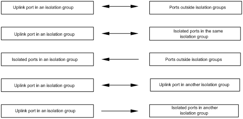
The feature isolates ports regardless of the VLANs that the ports are assigned to. In an isolation group, only one isolated port can unidirectionally connect to the uplink port, whereas all other ports are isolated at Layer 2. To enable ports in the isolation group to communicate with outside ports that belong to the same VLAN as the isolation group ports, follow these guidelines:
· When the switch is operating in hybrid mode, you must specify an uplink port for the isolation group. Figure 1 shows traffic communication among those ports.
· When the switch is operating in non-hybrid mode, the isolation group ports can communicate with the outside ports at Layer 2 bidirectionally without other configuration requirements.
Figure 1 Communication between ports in the same VLAN in port isolation
|
|
NOTE: The arrows in the previous figure indicate the directions that Layer 2 traffic is permitted to flow. |
|
|
IMPORTANT: · The isolated ports in an isolation group support the following functions only: MAC address learning, QoS actions (such as accounting, filter deny, car cir committed-information-rate red discard, and traffic mirroring) in the incoming direction of the ports, and link aggregation. · Do not configure Layer 2 protocols (such as GVRP) or Layer 3 protocols (such as multicast and routing) on the isolated ports in an isolation group. Doing so can cause network malfunction. |
Community VLAN
A community VLAN allows the ports in an isolation group to communicate with each other within the VLAN at Layer 2.
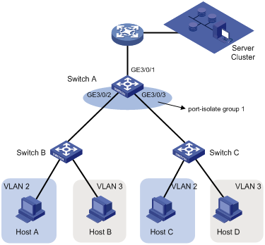
Figure 2 shows a network scenario that requires the community VLAN configuration.
· Switch B and Switch C communicate with a public server cluster through Switch A.
· Switch A connects to Switch B through GigabitEthernet 3/0/2, and connects to Switch C through GigabitEthernet 3/0/3.
· Both GigabitEthernet 3/0/2 and GigabitEthernet 3/0/3 are assigned to VLAN 2 and VLAN 3.
After GigabitEthernet 3/0/2 and GigabitEthernet 3/0/3 are assigned to isolation group 1, Switch B cannot communicate with Switch C at Layer 2, Host A cannot communicate with Host C although they both belong to VLAN 2, and Host B cannot communicate with Host D although they both belong to VLAN 3.
To enable Layer 2 communication between Host B and Host D, you can configure VLAN 3 as a community VLAN for isolation group 1.
Figure 2 Community VLAN in an isolation group
Configuration restrictions and guidelines
· Port isolation is available when the switch is operating in standalone mode or in IRF mode with enhanced-IRF disabled. For more information about IRF, see IRF Configuration Guide.
· You cannot configure the port isolation feature together with the MAC-based VLAN feature when the switch is operating in non-hybrid mode. For more information about MAC-based VLANs, see "Configuring VLANs." For more information about the system working modes, see Fundamentals Configuration Guide.
Port isolation configuration task list
|
Task |
Remarks |
|
Required. |
|
|
Required only when the switch is operating in hybrid mode. |
|
|
Optional. |
Assigning ports to an isolation group
|
Step |
Command |
Remarks |
|
1. Enter system view. |
system-view |
N/A |
|
2. Create an isolation group and enter isolation group view when the switch is operating in non-hybrid mode. |
port-isolate group group-number |
When the switch is operating in non-hybrid mode, you can use this command to directly enter the view of an existing isolation group. |
|
3. Exit isolation group view. |
quit |
This operation is required only when the switch is operating in non-hybrid mode. |
|
4. Enter interface view. |
· Enter Ethernet interface view: · Enter Layer 2 aggregate interface view: · Enter port group view: |
Use one of the commands. |
|
5. Assign the ports to the isolation group as isolated ports. |
port-isolate enable group group-number |
No ports are assigned to an isolation group by default. |
|
|
NOTE: The number of ports that can be assigned to an isolation group is not limited. |
Specifying the uplink port for an isolation group
When you specify the uplink port for an isolation group, follow these guidelines:
· Specify the uplink port for an isolation group when the switch is operating in hybrid mode.
· An isolation group can have only one uplink port. The uplink port you configured for an isolation group can overwrite the previous one, if any.
· You cannot configure an isolated port in an isolation group as the uplink port of any isolation group. However, you can assign the port in one isolation group to another isolation group. In this case, the port leaves the previous group and joins the new one.
· You cannot configure the uplink port of an isolation group as an isolated or uplink port of any other isolation group.
· The member port of an aggregation group cannot be configured as the uplink port of an isolation group and vice versa. If you assign a port to an aggregation group and to an isolation group as the uplink port at the same time, the aggregation group configuration will take effect and the isolation group configuration will be removed for backward configuration file compatibility. For more information about link aggregation, see "Configuring Ethernet link aggregation."
To specify the uplink port for an isolation group:
|
Step |
Command |
Remarks |
|
1. Enter system view. |
system-view |
N/A |
|
2. Enter interface view. |
· Enter Ethernet interface view: · Enter Layer 2 aggregate interface view: |
Use either command. |
|
3. Configure the port as the uplink port of an isolation group. |
port-isolate uplink-port group group-number |
An isolation group has no uplink port by default. |
Configuring community VLANs
The community VLAN configuration is available only when the switch is operating in non-hybrid mode.
To configure community VLANs for an isolation group:
|
Step |
Command |
Remarks |
|
1. Enter system view. |
system-view |
N/A |
|
2. Create an isolation group and enter isolation group view. |
port-isolate group group-number |
You can use this command to directly enter the view of an existing isolation group. |
|
3. Configure community VLANs. |
community-vlan vlan { vlan-id-list | all } |
By default, an isolation group does not contain any community VLANs. |
Displaying and maintaining port isolation
|
Task |
Command |
Remarks |
|
Display the port isolation information. |
display port-isolate group [ group-number ] [ | { begin | exclude | include } regular-expression ] |
Available in any view. |
Port isolation configuration examples
|
|
IMPORTANT: By default, Ethernet interfaces, VLAN interfaces, and aggregate interfaces are in DOWN state. Before configuring these interfaces, bring them up with the undo shutdown command. |
Port isolation without community VLAN configuration example
Network requirements
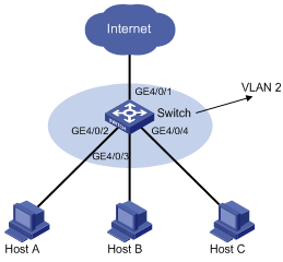
As shown in Figure 3, the switch is operating in hybrid mode and provides access to the Internet through GigabitEthernet 4/0/1. Ports GigabitEthernet 4/0/1 through GigabitEthernet 4/0/4 belong to VLAN 2.
Configure port isolation, so the switch prevents Host A, Host B, and Host C from communicating with one another at Layer 2, but allows them to access the Internet.
Configuration procedure
# Create VLAN 2 and assign ports to the VLAN.
<Switch> system-view
[Switch] vlan 2
[Switch-vlan2] port gigabitethernet 4/0/1 to gigabitethernet 4/0/4
[Switch-vlan2] quit
# Create isolation group 2.
[Switch] port-isolate group 2
# Assign ports GigabitEthernet 4/0/2, GigabitEthernet 4/0/3, and GigabitEthernet 4/0/4 to isolation group 2 as isolated ports.
[Switch] interface gigabitethernet 4/0/2
[Switch-GigabitEthernet4/0/2] port-isolate enable group 2
[Switch-GigabitEthernet4/0/2] quit
[Switch] interface gigabitethernet 4/0/3
[Switch-GigabitEthernet4/0/3] port-isolate enable group 2
[Switch-GigabitEthernet4/0/3] quit
[Switch] interface gigabitethernet 4/0/4
[Switch-GigabitEthernet4/0/4] port-isolate enable group 2
[Switch-GigabitEthernet4/0/4] quit
# Configure port GigabitEthernet 4/0/1 as the uplink port of isolation group 2.
[Switch] interface gigabitethernet 4/0/1
[Switch-GigabitEthernet4/0/1] port-isolate uplink-port group 2
[Switch-GigabitEthernet4/0/1] quit
Verifying the configuration
# Display information about isolation group 2.
[Switch] display port-isolate group 2
Port-isolate group information:
Uplink port support: YES
Group ID: 2
Uplink port: GigabitEthernet4/0/1
Group members:
GigabitEthernet4/0/2 GigabitEthernet4/0/3 GigabitEthernet4/0/4
Port isolation with community VLAN configuration example
Network requirements
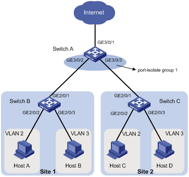
As shown in Figure 4, Switch A is operating in non-hybrid mode and accesses the Internet through GigabitEthernet 3/0/1. The company branches Site 1 and Site 2 transfer service traffic in VLAN 2 and VLAN 3, and are connected to Switch A through Switch B and Switch C, respectively.
Configure port isolation and community VLANs, so the switches allow the company hosts to access the Internet, enable Host B and Host D to exchange video conferencing traffic in VLAN 3, and isolate other Layer 2 traffic between Switch B and Switch C.
Configuration procedure
1. Configuring Switch A:
# Create VLAN 2 and VLAN 3, and assign trunk ports GigabitEthernet 3/0/2 and GigabitEthernet 3/0/3 to the VLANs.
<SwitchA> system-view
[SwitchA] vlan 2 to 3
[SwitchA] interface GigabitEthernet 3/0/2
[SwitchA-GigabitEthernet3/0/2] port link-type trunk
[SwitchA-GigabitEthernet3/0/2] port trunk permit vlan 2 3
[SwitchA-GigabitEthernet3/0/2] quit
[SwitchA] interface GigabitEthernet 3/0/3
[SwitchA-GigabitEthernet3/0/3] port link-type trunk
[SwitchA-GigabitEthernet3/0/3] port trunk permit vlan 2 3
[SwitchA-GigabitEthernet3/0/3] quit
# Create isolation group 1.
[SwitchA] port-isolate group 1
[SwitchA-port-isolate-group1] quit
# Assign ports GigabitEthernet 3/0/2 and GigabitEthernet 3/0/3 that connect to Switch B and Switch C to isolation group 1.
[SwitchA] interface GigabitEthernet 3/0/2
[SwitchA-GigabitEthernet3/0/2] port-isolate enable group 1
[SwitchA-GigabitEthernet3/0/2] quit
[SwitchA] interface GigabitEthernet 3/0/3
[SwitchA-GigabitEthernet3/0/3] port-isolate enable group 1
[SwitchA-GigabitEthernet3/0/3] quit
# Configure VLAN 3 as a community VLAN in isolation group 1.
[SwitchA] port-isolate group 1
[SwitchA-port-isolate-group1] community-vlan vlan 3
[SwitchA-port-isolate-group1] quit
2. Configuring Switch B:
# Create VLAN 2 and VLAN 3, assign GigabitEthernet 2/0/2 to VLAN 2, and assign GigabitEthernet 2/0/3 to VLAN 3.
<SwitchB> system-view
[SwitchB] vlan 2
[SwitchB-vlan2] port GigabitEthernet 2/0/2
[SwitchB-vlan2] vlan 3
[SwitchB-vlan3] port GigabitEthernet 2/0/3
[SwitchB-vlan3] quit
# Configure GigabitEthernet 2/0/1 as a trunk port and assign the port to VLAN 2 and VLAN 3.
[SwitchB] interface GigabitEthernet 2/0/1
[SwitchB-GigabitEthernet2/0/1] port link-type trunk
[SwitchB-GigabitEthernet2/0/1] port trunk permit vlan 2 3
3. Configure Switch C in the same way Switch B is configured.
Verifying the configuration
# Display information about isolation group 1 on Switch A.
[SwitchA] display port-isolate group 1
Port-isolate group information:
Uplink port support: NO
Group ID: 1
Group members:
GigabitEthernet3/0/2 GigabitEthernet3/0/3
The output shows that ports GigabitEthernet 3/0/2 and GigabitEthernet 3/0/3 are assigned to isolation group 1.
# Display the configuration of isolation group 1.
[SwitchA] port-isolate group 1
[SwitchA -port-isolate-group1] display this
#
port-isolate group 1
community-vlan vlan 3
#
return
The output shows that Switch A contains isolation group 1, in which VLAN 3 is a community VLAN.