- Table of Contents
- Related Documents
-
| Title | Size | Download |
|---|---|---|
| 01-IRF Configuration | 656.05 KB |
Contents
Multi-active handling procedure
General restrictions and configuration guidelines
Feature and IRF mode compatibility
Other configuration guidelines
Setup and configuration task list
Preconfiguring IRF member devices in standalone mode
Assigning a member ID to each IRF member device
Specifying a priority for each member device
Binding physical ports to IRF ports
Enabling enhanced IRF mode in standalone mode
Saving configuration to the next-startup configuration file
Setting the operating mode to IRF mode
Accessing the global active MPU of the IRF fabric
Accessing a standby MPU in the IRF fabric
Configuring IRF member devices in IRF mode
Assigning an IRF domain ID to the IRF fabric
Changing the member ID of a device
Changing the priority of a member device
Adding physical ports to an IRF port
Enabling enhanced IRF mode in IRF mode
Enabling auto reboot for IRF fabric merge
Configuring a member device description
Configuring IRF bridge MAC persistence
Enabling software auto-update for system software image synchronization
Setting the IRF link down report delay
Enabling IRF link failure detection and auto-recovery
Fast-restoring IRF configuration for a one-MPU member
Displaying and maintaining an IRF fabric
IRF fabric configuration examples
LACP MAD-enabled IRF configuration example
BFD MAD-enabled IRF configuration example
ARP MAD-enabled IRF configuration example
Four-chassis IRF fabric configuration example
H3C Intelligent Resilient Framework (IRF) technology creates a large IRF fabric from multiple devices to provide data center class availability and scalability. IRF virtualization technology offers processing power, interaction, unified management, and uninterrupted maintenance of multiple devices.
This book describes IRF concepts and guides you through the IRF setup procedure.
Hardware compatibility
An H3C S9500E switch can form an IRF fabric only with devices in the same series.
IRF benefits
IRF provides the following benefits:
· Simplified topology and easy management—An IRF fabric appears as one node and is accessible at a single IP address on the network. You can use this IP address to log in at any member device to manage all the members of the IRF fabric. In addition, you do not need to run the spanning tree feature among the IRF members.
· 1:N redundancy—In an IRF fabric, one member works as the master to manage and control the entire IRF fabric, and all the other members process services while backing up the master. When the master fails, all the other member devices elect a new master from among them to take over without interrupting services.
· IRF link aggregation—You can assign several physical links between neighboring members to their IRF ports to create a load-balanced aggregate IRF connection with redundancy.
· Multiple-chassis link aggregation—You can use the Ethernet link aggregation feature to aggregate the physical links between the IRF fabric and its upstream or downstream devices across the IRF members.
· Network scalability and resiliency—Processing capacity of an IRF fabric equals the total processing capacities of all the members. You can increase ports, network bandwidth, and processing capacity of an IRF fabric simply by adding member devices without changing the network topology.
Application scenario
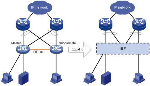
Figure 1 shows an IRF fabric that has two devices, which appear as a single node to the upper and lower layer devices.
Figure 1 IRF application scenario
Basic concepts
This section uses Figure 2 to describe the basic concepts that you might encounter when you work with IRF.
Figure 2 Two-chassis IRF fabric implementation schematic diagram
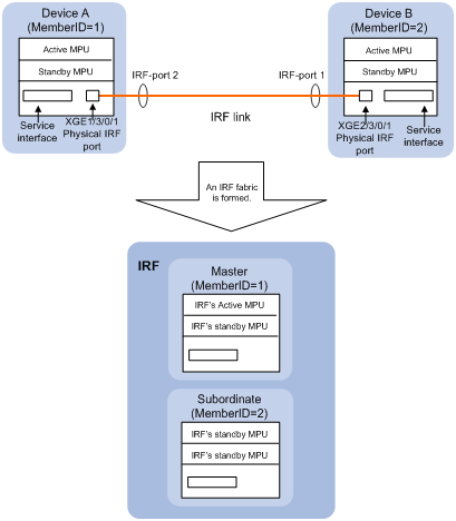
In this figure, Device A and Device B form a two-chassis IRF fabric that has four MPUs (one active and three standbys) and two times the number of interface cards that a single device provides. The IRF fabric manages both the physical and software resources of Device A and Device B in a centralized manner.
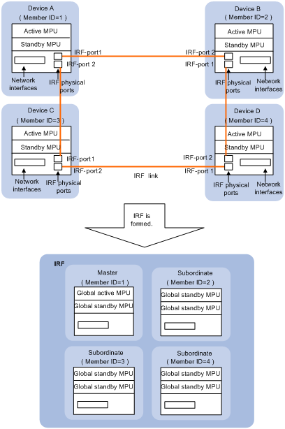
You can scale this two-chassis IRF fabric to a four-chassis IRF fabric for higher port density and availability, as shown in Figure 3.
Figure 3 Four-chassis IRF fabric implementation schematic diagram
Operating mode
A device operates in one of the following modes:
· Standalone mode—The device cannot form an IRF fabric with other devices.
· IRF mode—The device can form an IRF fabric with other devices.
IRF member roles
IRF uses two member roles: master and slave (called "subordinate" throughout the documentation).
When devices form an IRF fabric, they elect a master to manage the IRF fabric, and all other devices back up the master. When the master device fails, the other devices elect a new master automatically. For more information about master election, see "Master election."
MPU roles
Each IRF member device has one or two MPUs, which play different roles, as follows:
|
Role |
Description |
|
Global active MPU |
Active MPU of the master device. You configure and manage the entire IRF fabric at the CLI of the global active MPU. |
|
Local active MPU |
Active MPU that manages the local device. This MPU has the following responsibilities: · Manages the local device, including synchronizing configuration between the local active MPU and the local standby MPU, processing protocol packets, and creating and maintaining route entries. · Handles IRF related events, such as master election and topology collection. |
|
Standby MPU |
For the global active MPU, all other MPUs, including local active MPUs, are global standby MPUs. If a member device has two MPUs, the one backing up the local MPU is the local standby MPU from the perspective of the member device. |
IRF member ID
An IRF fabric uses member IDs to uniquely identify and manage its members. This member ID information is included as the first part of interface numbers and file paths to uniquely identify interfaces and files in an IRF fabric. For example, after you assign a device with member ID 2 to an IRF fabric, the name of interface GigabitEthernet 3/0/1 changes to GigabitEthernet 2/3/0/1, and the file path slot1#flash:/test.cfg changes to chassis2#slot1#flash:/test.cfg.
If two devices have the same IRF member ID, they cannot form an IRF fabric. If the IRF member ID of a device has been used in an IRF fabric, the device cannot join the fabric.
By default, the standby MPU is automatically assigned the same ID as the active MPU. You can change the standby MPU ID of a member device to quickly recover IRF configuration for a device that has only one MPU as described in "Fast-restoring IRF configuration for a one-MPU member."
IRF port
An IRF port is a logical interface for the connection between IRF member devices. Each IRF-capable device supports two IRF ports.
In standalone mode, the IRF ports are named IRF-port 1 and IRF-port 2.
In IRF mode, the IRF ports are named IRF-port n/1 and IRF-port n/2, where n is the member ID of the device. The two IRF ports are referred to as "IRF-port 1" and "IRF-port 2" in this book for simplicity.
An IRF port is activated when you bind a physical port to it. A maximum of 12 physical ports can be bound to an IRF port to increase the bandwidth and reliability of the IRF port. The physical ports assigned to the IRF port automatically form an aggregate IRF link. An IRF port goes down only if all its physical IRF ports are down.
For two neighboring devices, their IRF physical links must be bound to IRF-port 1 on one device and to IRF-port 2 on the other.
Physical IRF port
Physical IRF ports connect IRF member devices and must be bound to an IRF port. They forward the IRF protocol packets between IRF member devices and the data packets that must travel across IRF member devices.
IRF domain ID
One IRF fabric forms one IRF domain. IRF uses IRF domain IDs to uniquely identify IRF fabrics and prevent IRF fabrics from interfering with one another.
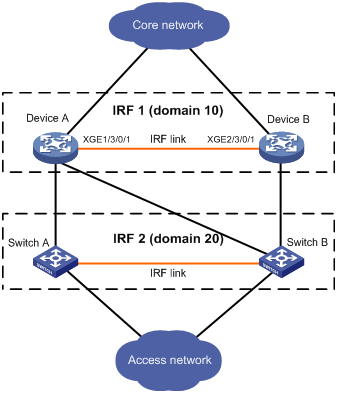
As shown in Figure 4, Device A and Device B form IRF fabric 1, and Switch A and Switch B form IRF fabric 2. The fabrics have LACP MAD detection links between them. When a member device in one IRF fabric receives an extended LACP packet for MAD detection, it looks at the domain ID in the packet to see whether the packet is from the local IRF fabric or from a different IRF fabric. Then, the device can handle the packet correctly.
Figure 4 A network that comprises two IRF domains
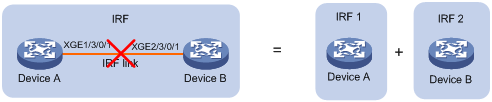
IRF split
IRF split occurs when an IRF fabric breaks up into two or more IRF fabrics because of IRF link failures, as shown in Figure 5. The split IRF fabrics operate with the same IP address and cause routing and forwarding problems on the network.
When you install the card where a physical IRF port resides, IRF split might occur. When you remove this kind of card, make sure there are at least two physical IRF ports in UP state on the member device, and they are not on the same card.
To quickly detect a multi-active collision, configure at least one MAD mechanisms (see "IRF multi-active detection").
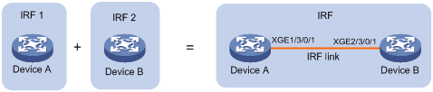
IRF merge
IRF merge occurs when two split IRF fabrics reunite or when you configure and connect two independent IRF fabrics to be one IRF fabric, as shown in Figure 6.
Member priority
Member priority determines the possibility of a member device to be elected the master. A member with higher priority is more likely to be elected the master.
The default member priority is 1. You can change the member priority of a member device to affect the master election result.
Master election
Master election is held each time the IRF fabric topology changes, for example, when the IRF fabric is established, the master device fails or is removed, or the IRF fabric splits, or IRF fabrics merge. Master election does not occur when two split IRF fabrics merge.
Master election uses the following rules in descending order:
1. Current master, even if a new member has higher priority.
When an IRF fabric is being formed, all member devices consider themselves as the master, and this rule is skipped.
2. Member with higher priority.
3. Member with the longest system uptime.
4. Member with the lowest bridge MAC address.
The IRF fabric is formed on election of the master.
During an IRF merge, the members of the IRF fabric that fails the master election must reboot to rejoin the IRF fabric that wins the election. The reboot can be performed automatically or manually, depending on the configuration. See "Enabling auto reboot for IRF fabric merge."
After a master election, all subordinate devices reboot with the configuration on the master. The configuration files of the subordinate members are still retained, but these files do not take effect in the IRF fabric. A subordinate member reboots with its own startup configuration file only when it is converted to the standalone mode.
IRF multi-active detection
An IRF link failure causes an IRF fabric to split in two IRF fabrics operating with the same Layer 3 configurations, including the same IP address. To avoid IP address collision and network problems, IRF uses the multi-active detection (MAD) mechanism to detect the presence of multiple identical IRF fabrics, handle collisions, and recover from faults.
Multi-active handling procedure
The multi-active handling procedure includes detection, collision handling, and failure recovery.
Detection
The MAD implementation of this device detects active IRF fabrics with the same Layer 3 global configuration by extending the Link Aggregation Control Protocol (LACP), the Bidirectional Forwarding Detection (BFD) protocol, or the Gratuitous Address Resolution (ARP) protocol.
These MAD mechanisms identify each IRF fabric with a domain ID and an active ID (the member ID of the master). If multiple active IDs are detected in a domain, MAD determines that an IRF collision or split has occurred.
You can use at least one of these mechanisms in an IRF fabric, depending on your network topology.
|
|
IMPORTANT: LACP MAD handles collisions in a different way than BFD MAD and ARP MAD. To avoid conflicts, do not use LACP MAD together with BFD MAD or ARP MAD. However, you can use BFD MAD and ARP MAD together. |
For a comparison of these MAD mechanisms, see "Configuring MAD."
Collision handling
MAD mechanisms remove multi-active collisions by setting one IRF fabric to the Detect state and other IRF fabrics to the Recovery state. The Detect-state IRF fabric is active. The Recovery-state IRF fabric is inactive. Only members in the Detect-state fabric can continue to forward traffic.
LACP MAD handles a multi-active collision in the following procedure:
1. Compares the number of members in each fabric.
2. Sets the fabric that has the most members to the Detect state and all other fabrics to the Recovery state.
3. If all IRF fabrics have the same number of members, compares the member IDs of their masters.
4. Sets the IRF fabric that has the lowest numbered master to the Detect state and all other fabrics to the Recovery (disabled) state.
5. Shuts down all physical network ports in the Recovery-state fabrics except their physical IRF ports and any ports you have specified with the mad exclude interface command.
In contrast, BFD MAD and ARP MAD do not compare the number of members in fabrics. They directly set the IRF fabric that has the lowest numbered master to the Detect state, set all other fabrics to the Recovery state, and take the same action on the network ports in Recovery-state fabrics as LACP MAD does.
To reduce the impact of IRF splits, H3C recommends that you specify the member device with the lowest member ID as the master in a two-chassis IRF fabric.
Failure recovery
To merge two split IRF fabrics, first repair the failed IRF link and remove the IRF link failure.
If the IRF fabric in Recovery state fails before the failure is recovered, repair the failed IRF fabric and the failed IRF link.
If the active IRF fabric fails before the failure is recovered, first enable the inactive IRF fabric to take over the active IRF fabric and protect services from being affected. After that, recover the MAD failure.
LACP MAD
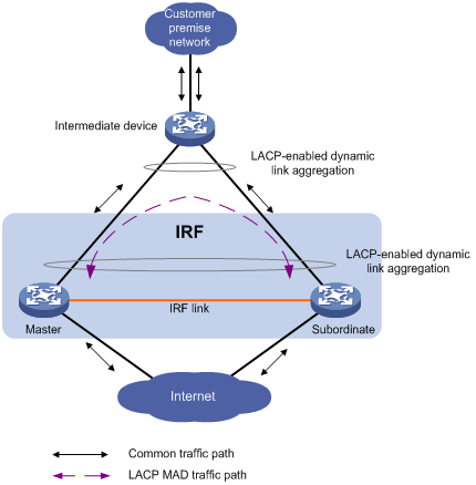
LACP MAD requires that every IRF member have a link with an intermediate device, and all these links form a dynamic link aggregation group, as shown in Figure 7. In addition, the intermediate device must be an H3C device that supports extended LACP for MAD.
The IRF member devices send extended LACP data units (LACPDUs) with type length values (TLVs) that convey the domain ID and active ID of the IRF fabric. The domain ID uniquely identifies an IRF device in the network, and the active ID is identical to the member ID of the master device in the IRF fabric. The intermediate device transparently forwards the extended LACPDUs received from one member device to all the other member devices:
· If the domain IDs and the active IDs in the extended LACPDUs sent by all the member devices are the same, the IRF fabric is integrated.
· If the extended LACPDUs convey the same domain ID but different active IDs, a split has occurred.
LACP MAD handles this situation as described in "Collision handling."
Figure 7 LACP MAD application scenario
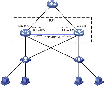
BFD MAD
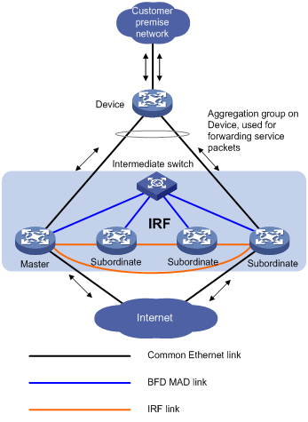
If the IRF fabric has only two member devices, BFD MAD detection can work with or without an intermediate device. If the IRF fabric has three or four member devices, there must be an intermediate device. Figure 8 and Figure 9 show two typical BFD MAD application scenarios.
To use BFD MAD:
· Set up dedicated BFD MAD link between each pair of IRF members or between each IRF member and the intermediate device. Only use the BFD MAD links for BFD MAD.
· Assign the ports connected by BFD MAD links to the same VLAN, create a VLAN interface for the VLAN, and assign a MAD IP address to each member on the VLAN interface.
The MAD IP addresses identify the member devices and must belong to the same subnet.
With BFD MAD, the master tries to establish BFD sessions with the other member devices by using its MAD IP address as the source IP address:
· If the IRF fabric is integrated, only the MAD IP address of the master is effective, and the master cannot establish a BFD session with any other member. If you perform the display bfd session command, the state of the BFD sessions is Down.
· When the IRF fabric splits, the IP addresses of the masters in the split IRF fabrics take effect, and the two masters can establish a BFD session. If you use the display bfd session command, the state of the BFD session between the two devices is Up.
Figure 8 BFD MAD application scenario (without an intermediate device)
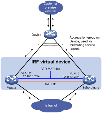
Figure 9 BFD MAD application scenario (with an intermediate device)
ARP MAD
ARP MAD detects multi-active collisions by using extended gratuitous ARP packets that convey the IRF domain ID and the active ID.
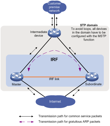
You can set up ARP MAD links between neighbor IRF member devices, or between each IRF member device and an intermediate device (see Figure 10). If an intermediate device is used, you must also run the spanning tree feature between the IRF fabric and the intermediate device.
Figure 10 ARP MAD application scenario
Each IRF member device compares the domain ID and the active ID in incoming extended gratuitous ARP packets with its domain ID and active ID:
· If the domain IDs are different, the extended gratuitous ARP packet is from a different IRF fabric, and the device does not continue to process the packet with the MAD mechanism.
· If the domain IDs are the same, the device compares the active IDs:
¡ If the active IDs are different, the IRF fabric has split.
¡ If the active IDs are the same, the IRF fabric is integrated.
To ensure a successful IRF setup, read the configuration restrictions and guidelines carefully before you connect and set up an IRF fabric.
General restrictions and configuration guidelines
Software requirements
All IRF member devices must run the same system software image version.
IRF size
An S9500E IRF fabric can have up to four chassis.
MPU and IRF port restrictions
· Make sure every IRF member has at least one MPU.
· Except for combo ports, any fiber or copper Ethernet ports can be used for IRF connection. H3C recommends using 10-GE fiber ports for high performance.
· When you connect two neighboring IRF members, connect IRF-port 1 on one member to IRF-port 2 on the other.
Suppose you have four chassis: A, B, C, and D. IRF-port 1 and IRF-port 2 are represented by A1 and A2 on chassis A, represented by B1 and B2 on chassis B, and so on. To connect the four chassis into a ring topology of A-B-C-D(A), the IRF link cabling scheme must be one of the following:
¡ A1-B2, B1-C2, C1-D2, and D1-A2.
¡ A2-B1, B2-C1, C2-D1, and D2-A1.
· Member devices can use different MPU models. An IRF fabric can have a mix of C1-suffix and C2-suffix MPUs or a mix of B1-suffix and B2-suffix MPUs, but it cannot have a mix of C1-/C2-suffix and B1-/B2-suffix MPUs (see Table 1). For example, devices that use the LSR1SRP2C1 MPU and devices that use the LSR1SRP2B1 MPU cannot form an IRF fabric.
Table 1 Support for IRF by S9500E members
|
MPU model suffix on member 1 (right) |
B1 |
B2 |
C1 |
C2 |
D1 |
|
MPU model suffix on member 2 (below) |
|||||
|
B1 |
√ |
√ |
× |
× |
× |
|
B2 |
√ |
√ |
× |
× |
× |
|
C1 |
× |
× |
√ |
√ |
× |
|
C2 |
× |
× |
√ |
√ |
× |
|
D1 |
× |
× |
× |
× |
√ |
|
|
NOTE: · In this table, the check mark (√) indicates that the IRF fabric can be formed and the cross mark (×) indicates that the IRF fabric cannot be formed. · If a device has two MPUs, the two MPUs must be the same model. |
IRF link redundancy
· For link redundancy and load sharing, bind up to 12 physical ports to one IRF port.
· Physical ports bound to an IRF port can be located on different cards.
· H3C recommends using multicard IRF links to avoid a card removal causing an IRF split.
Feature and IRF mode compatibility
To form an IRF fabric:
· All member devices in the IRF fabric must work in the same system operating mode and the mode cannot be the hybrid mode. For more information about the system operating mode, see Fundamentals Configuration Guide.
· All member devices in the IRF fabric must have the same acl ipv6 enable (or acl ipv6 disable) command setting. For more information about acl ipv6, see ACL and QoS Configuration Guide.
· All member devices in the IRF fabric must have the same setting for the acl mode command. For more information about acl mode, see ACL and QoS Configuration Guide.
· All member devices in the IRF fabric must have the same vpn popgo command setting. For more information about vpn popgo, see MPLS Configuration Guide.
· All member devices in the IRF fabric must have the same portal-roaming enable command setting. For more information about Portal, see Security Configuration Guide.
· All member devices in the IRF fabric must have the same irf mode enhanced command configuration. For more information about enhanced IRF mode, see "Enabling enhanced IRF mode in standalone mode" and "Enabling enhanced IRF mode in IRF mode."
MAD
· LACP MAD handles collisions in a different way than BFD MAD and ARP MAD. To avoid conflicts, do not use LACP MAD together with BFD MAD and ARP MAD. However, you can configure BFD MAD and ARP MAD together for prompt IRF split detection.
· If LACP or ARP MAD runs between two IRF fabrics, assign each fabric a unique IRF domain ID. For BFD MAD, this task is optional.
· To exclude a port from the shutdown action that is executed when an IRF fabric transits to the Recovery state, use the mad exclude interface command. To bring up a port after the IRF fabric transits to the Recovery state, you must use the mad restore command instead of the undo shutdown command to activate the entire IRF fabric.
Other configuration guidelines
· If a subordinate device uses the same next-startup configuration file name as the master device, the file might be overwritten depending on your configuration file management settings. To continue to use the configuration file after removing the device from the IRF fabric, back up the file before setting up the IRF fabric.
· Strictly follow the IRF fabric setup procedure described in "Setup and configuration task list" to plan the IRF fabric, identify IRF physical ports, connect IRF member devices, and configure basic settings.
· Assign each member a unique IRF member ID to make sure they can merge. You must reboot the members to validate the IRF member ID settings.
· If two IRF fabrics have the same bridge MAC address, they cannot merge.
· Assign the highest member priority to the device you want to use as the master.
· Assign the IRF fabric a unique IRF domain ID in a multi-IRF network.
· Save any configuration you have made to the startup configuration file before rebooting the IRF member devices.
Setup and configuration task list
H3C recommends the following IRF fabric setup and configuration procedure:
|
Task |
Remarks |
|
Required. |
|
|
2. Preconfiguring IRF member devices in standalone mode: ¡ Assigning a member ID to each IRF member device |
Required. |
|
Optional. If more than two devices are used to form one IRF fabric, this step is required. |
|
|
4. Saving configuration to the next-startup configuration file |
Required. |
|
Required. Make sure that they are interoperable. |
|
|
Required. |
|
|
Login to the global active MPU is required. From the active MPU, you can log in to a standby MPU to execute a limited set of maintenance commands. |
|
|
8. Configuring IRF member devices in IRF mode: ¡ Assigning an IRF domain ID to the IRF fabric ¡ Changing the member ID of a device ¡ Changing the priority of a member device ¡ Adding physical ports to an IRF port ¡ Enabling enhanced IRF mode in IRF mode ¡ Enabling auto reboot for IRF fabric merge ¡ Configuring a member device description ¡ Configuring IRF bridge MAC persistence ¡ Enabling software auto-update for system software image synchronization ¡ Setting the IRF link down report delay |
All these tasks are optional. Adding physical ports to an IRF port is required if you did not configure IRF port bindings in standalone mode.
Changing member IDs in an IRF fabric can void member ID-related configuration and cause unexpected problems. Before doing that, make sure you understand the impact on your live network. |
|
Optional. This task helps you fast-restore IRF configuration for one-MPU members before an MPU replacement. |
Planning the IRF fabric setup
Consider the following items when you plan an IRF fabric:
· Hardware compatibility and restrictions
· IRF fabric size
· Master device
· IRF physical ports
· Member ID and priority assignment scheme
· Fabric topology and cabling scheme
For more information about hardware and cabling, see the device installation guide.
Preconfiguring IRF member devices in standalone mode
Perform the tasks in this section on every IRF member device. These settings take effect on each member device after their operating mode changes to IRF.
Assigning a member ID to each IRF member device
A device by default operates in standalone mode without an IRF member ID. You must assign it a unique IRF member ID before changing its operating mode to IRF.
Execute the display irf configuration command and look at the MemberID field. If the device has no IRF member ID, the field displays two hyphens (--).
The member ID assigned to a device is saved in both active and standby MPUs of the device. If the standby MPU has a different member ID than the active MPU, for example, because of an MPU replacement, the member ID in the active MPU takes effect and is automatically updated to the standby MPU.
To set a member ID for the device in standalone mode:
|
Step |
Command |
Remarks |
|
1. Enter system view. |
system-view |
N/A |
|
2. Assign an IRF member ID to the device. |
irf member member-id |
By default, the device has no IRF member ID. |
Specifying a priority for each member device
IRF member priority represents the possibility for a device to be elected the master in an IRF fabric. The higher the priority, the higher the possibility.
To specify a priority for the device in standalone mode:
|
Step |
Command |
Remarks |
|
1. Enter system view. |
system-view |
N/A |
|
2. Specify a priority for the device. |
irf priority priority |
Optional. The default IRF member priority is 1. |
Binding physical ports to IRF ports
To establish an IRF connection between two devices, you must bind at least one physical port to IRF port 1 on one device and to IRF port 2 on the other. For link redundancy and load sharing, bind multiple physical ports to one IRF port.
A combo port cannot be bound to an IRF port. For information about combo ports, see Interface Configuration Guide.
Make sure the IRF physical ports are operating as Layer 2 interfaces. Layer 3 interfaces cannot be bound to IRF ports. You can set a physical port as a Layer 2 or Layer 3 interface by using the port link-mode { bridge | route } command (see Interface Configuration Guide).
In standalone mode, binding a physical port to an IRF port does not affect the running configuration of the port. However, when the operating mode changes to IRF mode, the default configuration of the physical IRF port restores, and you can only execute the shutdown and description commands on the physical port. For more information about the shutdown and description commands, see Interface Command Reference.
To bind physical ports to IRF ports:
|
Step |
Command |
Remarks |
|
1. Enter system view. |
system-view |
N/A |
|
2. Enter IRF port view. |
irf-port port-number |
N/A |
|
3. Bind a physical IRF port to the IRF port. |
port group interface interface-type interface-number |
By default, no physical ports are bound to any IRF port. Repeat this step to assign more physical ports to an IRF port. Every IRF port can have up to 12 physical ports. |
Enabling enhanced IRF mode in standalone mode
The enhanced IRF mode allows you to create an IRF fabric that has up to four member devices. You can enable enhanced IRF mode in both standalone and IRF modes.
Follow these guidelines when you configure the enhanced IRF mode in standalone mode:
· Each member device must have two MPUs.
· The member devices must be in ring topology and have no relay device in between. See Figure 12 and Figure 13.
· Connect every downstream device to each IRF member device and assign these links to one link aggregation group. See Figure 22.
· Use the save command to save the configuration after you enable the enhanced IRF mode.
Use undo irf mode enhanced to disable enhanced IRF mode.
· To successfully merge devices into an IRF fabric, make sure that the enhanced IRF mode is enabled or disabled on all the devices. Devices that use different enhanced IRF mode settings cannot form an IRF fabric.
· If the enhanced IRF mode is used, you must reboot all but one member device to complete IRF merge.
To enable enhanced IRF mode in standalone mode:
|
Step |
Command |
Remarks |
|
1. Enter system view. |
system-view |
N/A |
|
2. Enable enhanced IRF mode. |
irf mode enhanced |
By default, enhanced IRF mode is disabled. After the enhanced IRF mode is enabled, you cannot create Layer 3 Ethernet interfaces or subinterfaces or Layer 3 aggregation interfaces or subinterfaces. |
Saving configuration to the next-startup configuration file
Save the running configuration before converting to the IRF mode. The mode change requires a reboot, which can cause all unsaved settings to be lost.
Perform the following task in any view:
|
Task |
Command |
|
Save the running configuration to the next-startup configuration file. |
save [ safely ] [ force ] |
Connecting physical IRF ports
A good practice is to use 10-GE fiber ports as physical IRF ports.
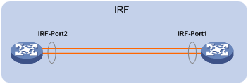
When you connect two neighboring IRF members, connect the physical ports of IRF-port 1 on one member to the physical ports of IRF-port 2 on the other, as shown in Figure 11.
If copper Ethernet ports are used, use straight-through or crossover copper Ethernet cables to connect them.
If fiber Ethernet ports are used, install transceiver modules and use fibers to connect them. For more information about transceiver modules, see the device installation guide.
To connect two IRF member devices through SFP+ ports, you can also use an SFP+ cable.
Figure 11 Connecting IRF physical ports
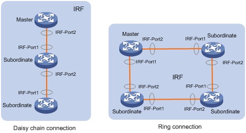
Connect the devices into a daisy chain topology or a ring topology. A ring topology is more reliable (see Figure 12).In ring topology, the failure of one IRF link does not cause the IRF fabric to split as in daisy chain topology. Instead, the IRF fabric changes to a daisy chain topology without interrupting network services.
Figure 12 Daisy chain topology vs. ring topology
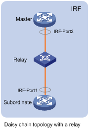
If two IRF member devices are far away from each other (for example, if they are in different cities), you can use a relay device to connect them, as shown in Figure 13.
Figure 13 Daisy chain topology with a relay
Setting the operating mode to IRF mode
By default, the device is operating in standalone mode. To assign the device to an IRF fabric, you must change its operating mode to IRF mode.
Before changing to IRF mode, use the display irf configuration command to verify that a member ID has been assigned to the device. If the MemberID field displays two hyphens (--), first assign a member ID to the device.
Base cards and the subcards can operate only when the device operates in standalone mode. Before switching the operating mode of the device, check whether the related services will be affected. For more information about base cards and subcards, see H3C S9500E Series Routing Switches Installation Guide.
For a device operating in IRF mode, you cannot configure the system operating mode to hybrid. For more information about the system operating mode, see Fundamentals Configuration Guide.
To set the operating mode of a device to IRF mode:
|
Step |
Command |
Remarks |
|
1. Enter system view. |
system-view |
N/A |
|
2. Set the operating mode to IRF mode. |
chassis convert mode irf |
The default operating mode is standalone mode. |
After you change the operating mode, the device automatically reboots to validate the change.
During the reboot, you can choose to have the system convert the startup configuration file automatically to prevent some slot- or interface-related configurations from becoming invalid. For example, the system can convert the slot slot-number parameter set in standalone mode to the chassis chassis-number slot slot-number parameter in IRF mode, and add the chassis ID in an interface number.
To restore the standalone mode, use the undo chassis convert mode irf command.
|
|
TIP: IRF generates packets on a device in IRF mode even if the device does not form an IRF fabric with any other device. To protect system resources, set a device to operate in standalone mode after removing it from an IRF fabric. |
Accessing the IRF fabric
The IRF fabric appears as one device after it is formed. You configure and manage all IRF members at the CLI of the global active MPU. All settings you made are automatically propagated to the IRF members.
When you log in to an IRF fabric, you are placed at the CLI of the global active MPU, regardless of at which member device you are logged in. After that, you can access the CLI of a standby MPU to execute a limited set of maintenance commands.
Accessing the global active MPU of the IRF fabric
Access an IRF fabric in one of the following ways:
· Local login—Log in through the AUX or console port of a member device.
· Remote login—Remotely log in at a Layer 3 Ethernet interface on any member devices by using methods including Telnet, the Web, or SNMP.
When you log in to an IRF fabric, you are placed at the CLI of its global active MPU, regardless of at which member device you are logged in. The global active MPU of the IRF fabric is the configuration and control center of the IRF fabric. You make configuration for the IRF fabric on the global active MPU, and the IRF fabric synchronizes the configurations to all standby MPUs in the virtual IRF device.
Accessing a standby MPU in the IRF fabric
You can log in to the CLI of a standby MPU for maintenance or debugging. When you change from the global active MPU's CLI to the standby MPU's CLI, you are placed in user view and the command prompt changes to <Sysname-Slave#member-ID/slot-number>, for example, <Sysname-Slave#1/0>. You can execute the following commands at a standby MPU's CLI:
· display
· quit
· return
· system-view
· debugging
· terminal debugging
· terminal logging
· terminal monitor
· terminal trapping
Perform the following task in user view:
|
Task |
Command |
Remarks |
|
Log in to a standby MPU in the IRF fabric. |
irf switch-to chassis chassis-number slot slot-number |
By default, you are placed at the global active MPU's CLI. |
To return to the CLI of the global active MPU, use the quit command.
Configuring IRF member devices in IRF mode
After you access the global active MPU's CLI, you can perform the tasks in this section or configure features in all other configuration guides for the device.
Assigning an IRF domain ID to the IRF fabric
This task is required for running LACP MAD or ARP MAD between two IRF fabrics. For BFD MAD, this task is optional.
One IRF fabric forms one IRF domain. IRF domain IDs prevent IRF fabrics from interfering with one another.
As shown in Figure 14, Device A and Device B form IRF fabric 1, and Switch A and Switch B form IRF fabric 2. The fabrics have LACP MAD detection links between them. When a member device in one IRF fabric receives an extended LACP packet for MAD detection, it looks at the domain ID in the packet to see whether the packet is from the local IRF fabric or from a different IRF fabric. Then, the device can handle the packet correctly.
Figure 14 A network that comprises two IRF domains
To assign a domain ID to an IRF fabric:
|
Step |
Command |
Remarks |
|
1. Enter system view. |
system-view |
N/A |
|
2. Assign a domain ID to the IRF fabric. |
irf domain domain-id |
Required if LACP MAD or ARP MAD is used, and optional if BFD MAD is used. By default, the domain ID of an IRF fabric is 0. |
Changing the member ID of a device
|
|
CAUTION: In IRF mode, an IRF member ID change can invalidate member ID-related settings and cause data loss. Be sure you fully understand its impact on your live network. |
The new member ID takes effect at reboot. After the device reboots, the settings on all member ID related physical resources (including common physical network ports) are removed and require reconfiguration, regardless of whether you have saved the configuration. In the configuration file, only the IRF port numbers, configurations on IRF ports, and priority of the device still take effect.
To change the member ID of a member device:
|
Step |
Command |
Remarks |
|
1. Enter system view. |
system-view |
N/A |
|
2. Change the member ID of a member device. |
irf member member-id renumber new-member-id |
N/A |
|
3. Save the running configuration. |
save [ safely ] [ force ] |
N/A |
|
4. Reboot the member device. |
reboot chassis chassis-number |
The chassis-number must be the same as the member-id specified in the irf member member-id renumber new-member-id command. |
Changing the priority of a member device
You can change the priority of a member device so it can be elected as the master at the next master election.
A member priority change can affect the master re-election result, but does not cause immediate master re-election.
To change the priority of a member device:
|
Step |
Command |
Remarks |
|
1. Enter system view. |
system-view |
N/A |
|
2. Specify a priority for a member device. |
irf member member-id priority priority |
Optional. The default IRF member priority is 1. |
Adding physical ports to an IRF port
An IRF port can have up to 12 physical ports. In IRF mode, you can add more physical ports (except for the combo port) to an IRF port. This task does not affect the ongoing traffic on the IRF port.
When you perform this task, follow the IRF physical port restrictions and configuration guidelines in "MPU and IRF port restrictions" and "Binding physical ports to IRF ports."
If a common Ethernet interface functions as a physical IRF port and is bound to an IRF port, you can execute the shutdown, description, flow-control, oam enable, oam loopback, and oam mode commands only on the physical IRF port. For more information about the shutdown, description, and flow-control commands, see Interface Command Reference.
To make sure that the configuration takes effect at the next device startup, save configurations to the startup configuration file that will be used at the next startup after binding a physical port to an IRF port or canceling the binding.
To configure IRF ports:
|
Step |
Command |
Remarks |
|
1. Enter system view. |
system-view |
N/A |
|
2. Enter Ethernet interface view or interface range view. |
· Enter interface range view: ¡ Method 1: ¡ Method 2: · Enter interface view: |
To shut down a range of physical IRF ports, enter interface range view. To shut down one physical IRF port, enter its interface view. |
|
3. Shut down the port or ports. |
shutdown |
If the system does not allow you to shut down a physical port, follow the system instruction to shut down its remote peer port. By default, the physical IRF ports are shut down. |
|
4. Return to system view. |
quit |
N/A |
|
5. Enter IRF port view. |
irf-port member-id/port-number |
N/A |
|
6. Bind each physical port to the IRF port. |
port group interface interface-type interface-number |
By default, no physical ports are bound to any IRF port. Repeat this step to assign multiple physical ports to the IRF port for link redundancy. Combo ports cannot be bound to IRF ports. |
|
7. Verify the binding configuration. |
display irf configuration [ | { begin | exclude | include } regular-expression ] |
Optional. Make sure that the binding is as expected. If the binding is incorrect, IRF cabling errors might occur, resulting in IRF establishment failure. |
|
8. Return to system view. |
quit |
N/A |
|
9. Enter physical IRF port view or interface range view. |
· Enter interface range view: ¡ Method 1: ¡ Method 2: · Enter interface view: |
N/A |
|
10. Bring up the port or ports. |
undo shutdown |
N/A |
|
11. Return to system view. |
quit |
N/A |
Enabling enhanced IRF mode in IRF mode
You can enable enhanced IRF mode in both standalone and IRF modes. To enable enhanced IRF mode in IRF mode, you should follow these guidelines:
· Each member device must have two MPUs.
· The member devices must be in ring topology and have no relay device in between. See Figure 12 and Figure 13.
· Connect every downstream device to each IRF member device and assign these links to one link aggregation group. See Figure 22.
· If neither Layer 3 (route mode) Ethernet interfaces nor VPLS and MAC-in-MAC instances exist, you can enable enhanced IRF mode directly.
· If Layer 3 Ethernet interfaces exist, you must first change them to Layer 2 (bridge mode) Ethernet interfaces at the prompt.
· If VPLS or MAC-in-MAC instances exist but no Layer 3 Ethernet interfaces exist, you must first reboot the device at the prompt.
For more information about Layer 3 Ethernet interfaces, see Interface Configuration Guide. For more information about VPLS, see MPLS Configuration Guide. For more information about MAC-in-MAC, see Layer 2—LAN Switching Configuration Guide.
· Use the save command to save the configuration after you enable the enhanced IRF mode.
· To successfully disable enhanced IRF mode with the undo irf mode enhanced command after you enable it in IRF mode, make sure that the IRF fabric has only up to two member devices and each member device has only one IRF port.
· To successfully merge IRF fabrics, make sure the enhanced IRF mode is enabled or disabled on each of the IRF fabrics. IRF fabrics that use different enhanced IRF mode settings cannot merge into one IRF fabric.
· If the enhanced IRF mode is used, you must reboot all but one member device to complete IRF merge.
To enable enhanced IRF mode:
|
Step |
Command |
Remarks |
|
1. Enter system view. |
system-view |
N/A |
|
2. Enable enhanced IRF mode. |
irf mode enhanced |
By default, enhanced IRF mode is disabled. After the enhanced IRF mode is enabled, you cannot create Layer 3 Ethernet interfaces or subinterfaces or Layer 3 aggregation interfaces or subinterfaces. |
Enabling auto reboot for IRF fabric merge
When two IRF fabrics merge, you must reboot the member devices in the IRF fabric that fails in the master election. The auto reboot function enables the IRF fabric to automatically reboot all its member devices to complete the merge.
This function can work only when it is enabled on both IRF fabrics that are merging.
This function does not take effect on the IRF fabric merge caused by binding a physical port to an IRF port in IRF mode. You must manually reboot the devices that have failed in the master selection to complete the merge.
To enable auto reboot for IRF fabric merge:
|
Step |
Command |
Remarks |
|
1. Enter system view. |
system-view |
N/A |
|
2. Enable auto reboot for IRF fabric merge. |
irf auto-merge enable |
Optional. By default, this function is disabled. |
Configuring a member device description
You can configure a description to describe the location or purpose of a member device.
To configure a description for a member device:
|
Step |
Command |
Remarks |
|
1. Enter system view. |
system-view |
N/A |
|
2. Configure the description of a member. |
irf member member-id description text |
Optional. By default, no member device description is configured. |
Configuring IRF bridge MAC persistence
An IRF fabric by default uses the bridge MAC address of the master device as its bridge MAC address. Layer 2 protocols, such as LACP, use this bridge MAC address to identify the IRF fabric. On a switched LAN, the bridge MAC address must be unique.
To avoid duplicate bridge MAC addresses, an IRF fabric can change its bridge MAC address automatically after its master leaves, but the change can cause transient traffic disruption.
Depending on your network condition, enable the IRF fabric to preserve or change its bridge MAC address after the master leaves. Available options include:
· irf mac-address persistent timer—Bridge MAC address of the IRF fabric is retained for 6 minutes after the master leaves. If the master does not return before the timer expires, the IRF fabric uses the bridge MAC address of the new master as its bridge MAC address. This option avoids unnecessary bridge MAC address change due to a device reboot, transient link failure, or purposeful link disconnection.
· irf mac-address persistent always—Bridge MAC address of the IRF fabric does not change after the master leaves.
· undo irf mac-address persistent—Bridge MAC address of the new master replaces the original one as soon as the old master leaves.
|
|
IMPORTANT: If ARP MAD is used, configure the undo irf mac-address persistent command to enable immediate bridge MAC address change after a master leaves. If VRRP load balancing or RPR is used, configure the the irf mac-address persistent always command to prevent the IRF bridge MAC address from changing. |
If two IRF fabrics have the same bridge MAC address, they cannot merge.
To configure the IRF bridge MAC persistence setting:
|
Step |
Command |
Remarks |
|
1. Enter system view. |
system-view |
N/A |
|
2. Configure IRF bridge MAC persistence. |
· Retain the bridge MAC
address even if the master has changed: · Preserve the bridge MAC address for 6 minutes after the master leaves: · Change the bridge MAC address as soon as the master leaves: |
By default, the IRF fabric's bridge MAC address is retained permanently even after the master leaves. |
Enabling software auto-update for system software image synchronization
The software auto-update function automatically propagates the system software image of the master to all members in the IRF fabric.
To join an IRF fabric, a device must use the same system software image as the master in the fabric.
When you add a device to the IRF fabric, the software auto-update function compares the system software versions of the device and the IRF master. If the versions are different, the device automatically downloads the system software image from the master, sets the downloaded image as the system software for the next reboot, and automatically reboots with the new system software image to rejoin the IRF fabric.
If software auto-update is disabled, you must manually update the device with the system software image of the master.
Configuration guidelines
Before you use the software auto-update function, follow these configuration prerequisites:
· The device you are adding to the IRF fabric is compatible with the software version running on the master. If it is not compatible, the automatic system software upgrading function cannot correctly work.
· The flash memory or CF card on the device you are adding to the IRF fabric has sufficient space for the new system software image.
· During auto upgrade of system software image, make sure all IRF links are OK and do not install, remove, or reboot the MPUs of member devices.
Configuration procedure
To enable an IRF fabric to automatically synchronize the software image of the master to the devices you are adding to the IRF fabric:
|
Step |
Command |
Remarks |
|
1. Enter system view. |
system-view |
N/A |
|
2. Enable software auto-update. |
irf auto-update enable |
Optional. By default, this function is enabled. |
Setting the IRF link down report delay
You can avoid link flapping causing frequent IRF splits and merges during a short time by configuring the IRF ports to delay reporting link down events. An IRF port works as follows:
· When the IRF link changes from up to down, the port does not immediately report the change to the IRF fabric. If the IRF link state is still down when the delay time is reached, the port reports the change to the IRF fabric.
· When the IRF link changes from down to up, the link layer immediately reports the event to the IRF fabric.
To set the IRF link down report delay:
|
Step |
Command |
Remarks |
|
1. Enter system view. |
system-view |
N/A |
|
2. Set the IRF link down report delay. |
irf link-delay interval |
Optional. The default IRF link down report delay is 0 millisecond. The recommended value range is 200 to 500 milliseconds. The greater the interval, the slower the service recovery. |
Enabling IRF link failure detection and auto-recovery
IRF link failure detection and auto-recovery automatically check the health of IRF links and make link recovery attempts when a failed IRF link is detected. The two functions are helpful for IRF fabrics that have more than one IRF link.
To enable IRF link failure detection and auto-recovery:
|
Step |
Command |
Remarks |
|
1. Enter system view. |
system-view |
N/A |
|
2. Enable IRF link failure detection. |
irf link-status detect enable |
Optional. By default, this function is enabled. IRF link failure detection must be enabled when a relay device is present between two member devices. |
|
3. Enable IRF link auto-recovery. |
irf link-status auto-recover enable |
Optional. By default, this function is enabled. You can enable IRF link auto-recovery only if IRF link failure detection has been enabled. |
When detecting an IRF link failure, the IRF link failure detection function handles the physical IRF port depending on the status of IRF link auto-recovery:
· If IRF link auto-recovery is enabled, the IRF link failure detection feature disables the physical IRF port to receive packets, and outputs a log message every 10 seconds (for example, "IRF member port GigabitEthernet1/4/0/1 does not work in receive direction").
¡ If the IRF fabric splits after the disable action, the physical IRF port can continue to receive packets.
¡ If you disable IRF link failure detection or auto-recovery after the disable action, the physical IRF port shuts down. To bring the port up, use the undo shutdown command.
· If IRF link auto-recovery is disabled, the IRF link failure detection feature shuts down the physical IRF port.
¡ The port stays in DOWN state even if you enable the IRF link auto-recovery function. To bring the port up, use the undo shutdown command.
¡ If the IRF fabric splits, the physical IRF ports in DOWN state change to the previous state.
Configuring MAD
The following MAD mechanisms are available for detecting multi-active collisions in different network scenarios:
· LACP MAD
· BFD MAD
· ARP MAD.
LACP MAD handles collisions in a different way than BFD MAD and ARP MAD. To avoid conflicts, do not use LACP MAD together with BFD MAD and ARP MAD. However, you can use BFD MAD and ARP MAD together.
Table 2 provides a reference for you to make a MAD mechanism selection decision.
Table 2 A comparison of the MAD mechanisms
|
MAD mechanism |
Advantages |
Disadvantages |
Application scenario |
|
LACP MAD |
· Detection speed is fast. · Requires no MAD-dedicated physical ports or interfaces. |
Requires an intermediate H3C device that supports LACP MAD packets. |
Link aggregation is used between the IRF fabric and its upstream or downstream device. For information about LACP, see Layer 2—LAN Switching Configuration Guide. |
|
BFD MAD |
· Detection speed is fast. · No intermediate device is required. · Intermediate device, if used, can come from any vendor. |
· Requires MAD dedicated physical ports and Layer 3 interfaces, which cannot be used for transmitting user traffic. · If no intermediate device is used, the IRF members must be fully meshed. · If an intermediate device is used, every IRF member must connect to the intermediate device. |
· No special requirements for network scenarios. · If no intermediate device is used, this mechanism is only suitable for IRF fabrics that have a small number of members that are geographically close to one another. For information about BFD, see High Availability Configuration Guide. |
|
ARP MAD |
· No intermediate device is required. · Intermediate device, if used, can come from any vendor. · Requires no MAD dedicated ports. |
· Detection speed is slower than BFD MAD and LACP MAD. · The spanning tree feature must be enabled. |
Spanning tree-enabled non-link aggregation IPv4 network scenario. For information about ARP, see Layer 3—IP Services Configuration Guide. |
Configuring LACP MAD
When you use LACP MAD, follow these guidelines:
· The intermediate device must be an H3C device that support extended LACP for MAD.
· If the intermediate device is an IRF fabric, assign the two IRF fabrics different domain IDs for correct split detection. False split detection causes IRF splits.
· Use dynamic link aggregation mode. MAD is LACP dependent. Even though LACP MAD can be configured on both static and dynamic aggregate interfaces, it takes effect only on dynamic aggregate interfaces.
· Configure link aggregation settings also on the intermediate device.
To configure LACP MAD:
|
Step |
Command |
Remarks |
|
1. Enter system view. |
system-view |
N/A |
|
2. Assign a domain ID to the IRF fabric. |
irf domain domain-id |
By default, the domain ID of an IRF fabric is 0. |
|
3. Create an aggregate interface. |
interface bridge-aggregation interface-number |
Perform this step also on the intermediate device. |
|
4. Configure the aggregation group to operate in dynamic aggregation mode. |
link-aggregation mode dynamic |
By default, the aggregation group operates in static aggregation mode. Perform this step also on the intermediate device. |
|
5. Enable LACP MAD detection. |
mad enable |
By default, LACP MAD is disabled. This command can be configured on both static and dynamic aggregate interfaces, but it takes effect only on dynamic aggregate interfaces. This is because this detection method depends on LACP. |
|
6. Return to system view. |
quit |
N/A |
|
7. Enter Ethernet interface view or interface range view. |
· Enter interface range view: ¡ Method 1: ¡ Method 2: · Enter Ethernet interface view: |
To assign a range of ports to the aggregation group, enter interface range view. To assign one port to the aggregation group, enter Ethernet interface view. |
|
8. Assign the port or port range to the specified aggregation group. |
port link-aggregation group number |
Multichassis link aggregation is allowed. Perform this step on the intermediate device as well. |
Configuring BFD MAD
When you configure BFD MAD, follow these guidelines:
|
Category |
Restrictions and guidelines |
|
BFD MAD VLAN |
· Do not enable BFD MAD on VLAN-interface 1. · If you are using an intermediate device, assign the ports of BFD MAD links to the BFD MAD VLAN on the device. · The IRF fabrics in a network must use different BFD MAD VLANs. |
|
BFD MAD VLAN and feature compatibility |
· Do not use the BFD MAD VLAN for any purpose other than configuring BFD MAD. Layer 2 or Layer 3 features, including ARP and LACP, cannot work on the BFD MAD-enabled VLAN interface or any port in the VLAN. If you configure any other feature on the VLAN, neither the configured feature nor the BFD MAD function will work correctly. · Disable the spanning tree feature on any port in the BFD MAD VLAN. The MAD function is mutually exclusive with the spanning tree feature. · Do not bind a BFD MAD-enabled VLAN interface to any VPN instance. The MAD function is mutually exclusive with VPN. |
|
MAD IP address |
· To avoid problems, only use the mad ip address command to configure IP addresses on the BFD MAD-enabled VLAN interface. Do not configure an IP address with the ip address command or configure a VRRP virtual address on the BFD MAD-enabled VLAN interface. · All MAD IP addresses on the BFD MAD-enabled VLAN interface must be on the same subnet. |
To configure BFD MAD:
|
Step |
Command |
Remarks |
|
1. Enter system view. |
system-view |
N/A |
|
2. Create a new VLAN dedicated to BFD MAD detection. |
vlan vlan-id |
The default VLAN on the device is VLAN 1. |
|
3. Return to system view. |
quit |
N/A |
|
4. Enter Ethernet interface view or interface range view. |
· Enter interface range view: ¡ Method 1: ¡ Method 2: · Enter Ethernet interface view: |
To assign a range of ports to the BFD MAD VLAN, enter interface range view. To assign one port to the BFD MAD VLAN, enter Ethernet interface view. |
|
5. Assign the port or the port range to the BFD MAD VLAN. |
· Assign the port to the VLAN as an access port: · Assign the port to the VLAN as a trunk port: · Assign the port to the VLAN as a hybrid port: |
Choose one command depending on the port type. BFD MAD has no requirement for the link type of the detection port. The default link type of a port is access. |
|
6. Return to system view. |
quit |
N/A |
|
7. Enter VLAN interface view. |
interface vlan-interface interface-number |
N/A |
|
8. Enable BFD MAD. |
mad bfd enable |
By default, BFD MAD is disabled. |
|
9. Configure a MAD IP address for the VLAN interface on the specified member. |
mad ip address ip-address { mask | mask-length } member member-id |
By default, no MAD IP address is configured on any VLAN interface. Repeat this step to assign a MAD IP address to each member device on the VLAN interface. The MAD IP address must not be on the same subnet as any IP address configured on any member device. |
Configuring ARP MAD
When you configure ARP MAD, follow these guidelines:
· Use a VLAN dedicated to ARP MAD.
· If an intermediate device is used, you can use common data links as ARP MAD links. If no intermediate device is used, set up dedicated ARP MAD links between IRF member devices.
· If an intermediate device is used, make sure the following requirements are met:
¡ Run the spanning tree feature between the IRF fabric and the intermediate device.
¡ Enable the IRF fabric to change its bridge MAC address as soon as the master leaves.
¡ Create an ARP MAD VLAN and assign the ports on the ARP MAD links to the VLAN.
¡ If the intermediate device is in an IRF fabric, assign this fabric a different domain ID than the ARP MAD-enabled fabric to avoid false detection of IRF split.
To configure ARP MAD:
|
Step |
Command |
Remarks |
|
1. Enter system view. |
system-view |
N/A |
|
2. Assign a domain ID to the IRF fabric. |
irf domain domain-id |
By default, the domain ID of an IRF fabric is 0. |
|
3. Configure the IRF bridge MAC address to change as soon as the master leaves. |
undo irf mac-address persistent |
By default, the IRF fabric's bridge MAC address is retained permanently even after the master leaves. |
|
4. Create a VLAN dedicated to ARP MAD. |
vlan vlan-id |
The default VLAN on the device is VLAN 1. |
|
5. Return to system view. |
quit |
N/A |
|
6. Enter Ethernet interface view or interface range view. |
· Enter interface range view: ¡ Method 1: ¡ Method 2: · Enter Ethernet interface view: |
To assign a range of ports to the ARP MAD VLAN, enter interface range view. To assign one port to the ARP MAD VLAN, enter Ethernet interface view. |
|
7. Assign the port or port range to the ARP MAD VLAN. |
· Assign the port to the VLAN as an access port: · Assign the port to the VLAN as a trunk port: · Assign the port to the VLAN as a hybrid port: |
Choose one command depending on the port type. ARP MAD has no requirement for the link type. The default link type of a port is access. |
|
8. Return to system view. |
quit |
N/A |
|
9. Enter VLAN interface view. |
interface vlan-interface interface-number |
N/A |
|
10. Assign the interface an IP address. |
ip address ip-address { mask | mask-length } |
By default, no IP address is assigned to any VLAN interface. |
|
11. Enable ARP MAD. |
mad arp enable |
By default, ARP MAD is disabled. |
Excluding a port from the shut down action upon detection of multi-active collision
|
|
CAUTION: Excluding a VLAN interface and its Layer 2 ports from the shutdown action introduces IP collision risks because the VLAN interface might be active on both the active and inactive IRF fabrics. |
By default, all ports (except the console and physical IRF ports) shut down automatically when the IRF fabric transits to Recovery state.
You can exclude a port from the shut down action for management or other special purposes. For example:
· Exclude a port from the shut down action, so you can Telnet to the port for managing the device.
· Exclude a VLAN interface and its Layer 2 Ethernet interface from the shut down action, so you can log in through the VLAN interface.
To configure a port to not shut down when the IRF fabric changes to the Recovery state:
|
Step |
Command |
Remarks |
|
1. Enter system view. |
system-view |
N/A |
|
2. Configure a port to not shut down when the IRF fabric transits to the Recovery state. |
mad exclude interface interface-type interface-number |
By default, all network ports on a Recovery-state IRF fabric are shut down, except for the IRF physical ports and console port. |
Recovering an IRF fabric
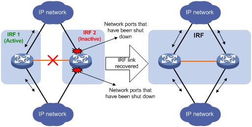
After the failed IRF link between two split IRF fabrics is recovered, log in to the inactive IRF fabric, and use the reboot command to reboot all its members. If the irf auto-merge enable command has been configured, the inactive IRF member devices automatically reboot after the failed link is recovered. After these member devices join the active IRF fabric as subordinates, IRF merge is complete, as shown in Figure 15
Figure 15 Recovering the IRF fabric
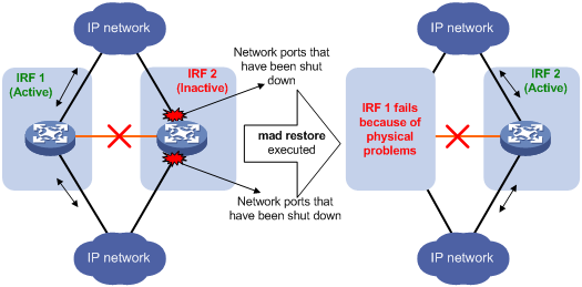
If the active IRF fabric has failed, for example, because of device or link failures, before the IRF link is recovered (see Figure 16), use the mad restore command on the inactive IRF fabric to change its MAD state to Detect and bring up all physical ports that were shut down by MAD. After you repair the IRF link, the two parts merge into a unified IRF fabric.
Figure 16 Active IRF fabric fails before the IRF link is recovered
To manually recover an inactive IRF fabric:
|
Step |
Command |
|
1. Enter system view. |
system-view |
|
2. Recover the inactive IRF fabric. |
mad restore |
After the IRF fabric is recovered, all ports that have been shut down by MAD come up automatically.
Fast-restoring IRF configuration for a one-MPU member
|
|
CAUTION: Use the set irf commands only for fast-restoring IRF configuration. This command might cause unknown errors in other application scenarios. |
If a member device has only one MPU, you must reconfigure the basic IRF settings for the device after its MPU is damaged. This section describes a fast method for restoring IRF configuration for one-MPU member devices.
|
|
NOTE: H3C recommends performing fast IRF configuration restoration in IRF mode. |
The recovery procedure differs depends on whether a two-chassis device is available. This section assumes that the failed member device is Device A.
If a two-MPU member device (Device B in this example) is available, use the following procedure:
|
Step |
Command |
|
1. Save the running configuration to the configuration file used at the next startup. |
save [ safely ] [ force ] |
|
2. Change Device B's member ID on the standby MPU to be the same as that of Device A. |
· In IRF mode: · In standalone mode: |
|
3. Remove the damaged MPU from Device A, and insert Device B's standby MPU into Device A. |
N/A |
If each member device has only one MPU, use the following procedure:
|
Step |
Command |
|
1. Save the running configuration to the configuration file used at the next startup. |
save [ safely ] [ force ] |
|
2. Insert a new MPU into the member device working correctly, for example, Device B. |
N/A |
|
3. Copy the configuration file on Device B's active MPU to the standby MPU. |
copy fileurl-source fileurl-dest |
|
4. Set the configuration file for next startup. |
startup saved-configuration cfgfile |
|
5. Change Device B's member ID on the standby MPU to be the same as that of Device A. |
· In IRF mode: · In standalone mode: |
|
6. Remove the damaged MPU from Device A, and insert Device B's standby MPU into Device A. |
N/A |
Displaying and maintaining an IRF fabric
|
Task |
Command |
Remarks |
|
Display information about the IRF fabric. |
display irf [ | { begin | exclude | include } regular-expression ] |
Available in any view. |
|
Display the IRF fabric topology. |
display irf topology [ | { begin | exclude | include } regular-expression ] |
Available in any view. |
|
Display IRF configuration. |
display irf configuration [ | { begin | exclude | include } regular-expression ] |
Available in any view. |
|
Display IRF link information. |
display irf link |
Available in any view. |
|
Display MAD configuration. |
display mad [ verbose ] [ | { begin | exclude | include } regular-expression ] |
Available in any view. |
|
Display restricted ports. |
display restricted port [ chassis chassis-number slot slot-number ] [ | { begin | exclude | include } regular-expression ] |
Available in any view. A restricted port does not receive or forward multicast packets. |
IRF fabric configuration examples
By default, Ethernet, VLAN, and aggregate interfaces are down. To configure these types of interfaces, execute the undo shutdown command to bring them up.
LACP MAD-enabled IRF configuration example
Network requirements
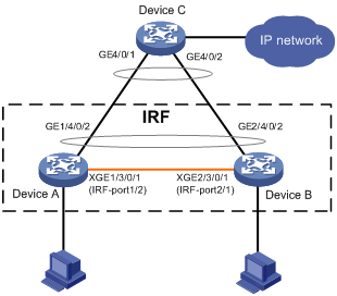
Set up a two-chassis IRF fabric at the access layer of the enterprise network in Figure 17.
Configure LACP MAD on the multichassis aggregation to Device C, an H3C device that supports extended LACP.
Configuration procedure
1. Configure Device A:
# Assign member ID 1 to Device A, and bind Ten-GigabitEthernet 3/0/1 to IRF-port 2.
<Sysname> system-view
[Sysname] irf member 1
Info: Member ID change will take effect after the switch reboots and operates in IRF mode.
[Sysname] irf-port 2
[Sysname-irf-port2] port group interface ten-gigabitethernet 3/0/1
[Sysname-irf-port2] quit
[Sysname] interface ten-gigabitethernet 3/0/1
[Sysname-Ten-GigabitEthernet3/0/1] undo shutdown
[Sysname-Ten-GigabitEthernet3/0/1] quit
# Save the configuration.
[Sysname] save
The current configuration will be written to the device. Are you sure? [Y/N]:y
Please input the file name(*.cfg)[flash:/startup.cfg]
(To leave the existing filename unchanged, press the enter key):
flash:/startup.cfg exists, overwrite? [Y/N]:y
Validating file. Please wait.....................................
The current configuration is saved to the active main board successfully.
Configuration is saved to device successfully.
# Enable IRF mode.
[Sysname] chassis convert mode irf
The device will switch to IRF mode and reboot. You are recommended to save the current running configuration and specify the configuration file for the next startup. Continue? [Y/N]:y
Do you want to convert the content of the next startup configuration file flash:/startup.cfg to make it available in IRF mode? [Y/N]:y
Please wait...
Saving the converted configuration file to the main board succeeded.
Slot 1:
Saving the converted configuration file succeeded.
Now rebooting, please wait...
2. Configure Device B:
# Assign member ID 2 to Device B, and bind Ten-GigabitEthernet 3/0/1 to IRF-port 1.
<Sysname> system-view
[Sysname] irf member 2
Info: Member ID change will take effect after the switch reboots and operates in IRF mode.
[Sysname] irf-port 1
[Sysname-irf-port1] port group interface ten-gigabitethernet 3/0/1
[Sysname-irf-port1] quit
[Sysname] interface ten-gigabitethernet 3/0/1
[Sysname-Ten-GigabitEthernet3/0/1] undo shutdown
[Sysname-Ten-GigabitEthernet3/0/1] quit
# Save the configuration.
[Sysname] save
The current configuration will be written to the device. Are you sure? [Y/N]:y
Please input the file name(*.cfg)[flash:/startup.cfg]
(To leave the existing filename unchanged, press the enter key):
flash:/startup.cfg exists, overwrite? [Y/N]:y
Validating file. Please wait.....................................
The current configuration is saved to the active main board successfully.
Configuration is saved to device successfully.
# Connect the two devices as shown in Figure 17. Log in to Device B.
# Enable IRF mode.
[Sysname] chassis convert mode irf
The device will switch to IRF mode and reboot. You are recommended to save the current running configuration and specify the configuration file for the next startup. Continue? [Y/N]:y
Do you want to convert the content of the next startup configuration file flash:/startup.cfg to make it available in IRF mode? [Y/N]:y
Please wait...
Saving the converted configuration file to the main board succeeded.
Slot 1:
Saving the converted configuration file succeeded.
Now rebooting, please wait...
Device B and Device A form an IRF fabric after Device B reboots.
3. Configure LACP MAD:
# Assign domain ID 1 to the IRF fabric.
<Sysname> system-view
[Sysname] irf domain 1
# Create a dynamic aggregate interface, and enable LACP MAD.
<Sysname> system-view
[Sysname] interface bridge-aggregation 2
[Sysname-Bridge-Aggregation2] link-aggregation mode dynamic
[Sysname-Bridge-Aggregation2] mad enable
This command will enable LACP MAD on the aggregate interface. Continue? [Y/N]: Y
You need to assign a domain ID (range: 0-4294967295)
[Current domain is: 1]:
The assigned domain ID is: 1
Info: MAD LACP only enable on dynamic aggregation interface
[Sysname-Bridge-Aggregation2] quit
# Assign GigabitEthernet 1/4/0/2 and GigabitEthernet 2/4/0/2 to the aggregate interface.
Sysname] interface gigabitethernet 1/4/0/2
[Sysname-GigabitEthernet1/4/0/2] port link-aggregation group 2
[Sysname-GigabitEthernet1/4/0/2] quit
[Sysname] interface gigabitethernet 2/4/0/2
[Sysname-GigabitEthernet2/4/0/2] port link-aggregation group 2
[Sysname-GigabitEthernet2/4/0/2] quit
4. Configure Device C as the intermediate device:
|
|
IMPORTANT: If the intermediate device is also an IRF fabric, assign the two IRF fabrics different domain IDs for correct split detection. False detection causes IRF split. |
# Create a dynamic aggregate interface.
<Sysname> system-view
[Sysname] interface bridge-aggregation 2
[Sysname-Bridge-Aggregation2] link-aggregation mode dynamic
[Sysname-Bridge-Aggregation2] quit
# Assign ports GigabitEthernet 4/0/1 and GigabitEthernet 4/0/2 to the dynamic aggregate interface.
[Sysname] interface gigabitethernet 4/0/1
[Sysname-GigabitEthernet4/0/1] port link-aggregation group 2
[Sysname-GigabitEthernet4/0/1] quit
[Sysname] interface gigabitethernet 4/0/2
[Sysname-GigabitEthernet4/0/2] port link-aggregation group 2
[Sysname-GigabitEthernet4/0/2] quit
When the IRF links fail, the system outputs IRF link problem and card failure error messages. Because it has a lower member ID than Device A, Device B transits to the Recovery state and shuts down all its ports except those excluded from the shutdown action.
BFD MAD-enabled IRF configuration example
Network requirements
Set up an IRF fabric at the distribution layer of the network as shown in Figure 18.
Configure BFD MAD in the IRF fabric and set up BFD MAD links between the member devices.
Disable the spanning tree feature on the ports used for BFD MAD, because the two features conflict with each other.
Assign the highest member priority to Device A so it can be elected the master.
Configuration procedure
1. Configure Device A:
# Set the member ID 1 to Device A, and bind port Ten-GigabitEthernet 3/0/1 to IRF-port 2.
<Sysname> system-view
[Sysname] irf member 1
Info: Member ID change will take effect after the switch reboots and operates in IRF mode.
[Sysname] irf-port 2
[Sysname-irf-port2] port group interface ten-gigabitethernet 3/0/1
[Sysname-irf-port2] quit
[Sysname] interface ten-gigabitethernet 3/0/1
[Sysname-Ten-GigabitEthernet3/0/1] undo shutdown
[Sysname-Ten-GigabitEthernet3/0/1] quit
# Specify the priority of Device A as 12 to make sure it is elected as the master when the IRF fabric is established.
[Sysname] irf priority 12
# Save the configuration.
[Sysname] save
The current configuration will be written to the device. Are you sure? [Y/N]:y
Please input the file name(*.cfg)[flash:/startup.cfg]
(To leave the existing filename unchanged, press the enter key):
flash:/startup.cfg exists, overwrite? [Y/N]:y
Validating file. Please wait.....................................
The current configuration is saved to the active main board successfully.
Configuration is saved to device successfully.
# Enable IRF mode.
<Sysname> system-view
[Sysname] chassis convert mode irf
The device will switch to IRF mode and reboot. You are recommended to save the current running configuration and specify the configuration file for the next startup. Continue? [Y/N]:y
Do you want to convert the content of the next startup configuration file flash:/startup.cfg to make it available in IRF mode? [Y/N]:y
Please wait...
Saving the converted configuration file to the main board succeeded.
Slot 1:
Saving the converted configuration file succeeded.
Now rebooting, please wait...
2. Configure Device B:
# Set the member ID 2 to Device B, and bind port Ten-GigabitEthernet 3/0/1 to IRF-port 1.
<Sysname> system-view
[Sysname] irf member 2
Info: Member ID change will take effect after the switch reboots and operates in IRF mode.
[Sysname] irf-port 1
[Sysname-irf-port1] port group interface ten-gigabitethernet 3/0/1
[Sysname-irf-port1] quit
[Sysname] interface ten-gigabitethernet 3/0/1
[Sysname-Ten-GigabitEthernet3/0/1] undo shutdown
[Sysname-Ten-GigabitEthernet3/0/1] quit
# Specify the priority of Device B as 26.
[Sysname] irf priority 26
# Save the configuration.
[Sysname] save
The current configuration will be written to the device. Are you sure? [Y/N]:y
Please input the file name(*.cfg)[flash:/startup.cfg]
(To leave the existing filename unchanged, press the enter key):
flash:/startup.cfg exists, overwrite? [Y/N]:y
Validating file. Please wait.....................................
The current configuration is saved to the active main board successfully.
Configuration is saved to device successfully.
# Connect the two devices as shown in Figure 18. Log in to Device B.
# Enable IRF mode.
<Sysname> system-view
[Sysname] chassis convert mode irf
The device will switch to IRF mode and reboot. You are recommended to save the current running configuration and specify the configuration file for the next startup. Continue? [Y/N]:y
Do you want to convert the content of the next startup configuration file flash:/startup.cfg to make it available in IRF mode? [Y/N]:y
Please wait...
Saving the converted configuration file to the main board succeeded.
Slot 1:
Saving the converted configuration file succeeded.
Now rebooting, please wait...
Device B and Device A form an IRF fabric after Device B reboots.
3. Configure BFD MAD:
# Create VLAN 3, and add port GigabitEthernet 1/4/0/1 (located on Device A) and port GigabitEthernet 2/4/0/1 (located on Device B) to VLAN 3.
<Sysname> system-view
[Sysname] interface range gigabitethernet 1/4/0/1 gigabitethernet 2/4/0/1
[Sysname-if-range] port link-mode bridge
[Sysname-if-range] quit
[Sysname] vlan 3
[Sysname-vlan3] port gigabitethernet 1/4/0/1 gigabitethernet 2/4/0/1
[Sysname-vlan3] quit
# Create VLAN-interface 3, and configure a MAD IP address for each member device on the VLAN interface.
[Sysname] interface vlan-interface 3
[Sysname-Vlan-interface3] mad bfd enable
This command will enable BFD MAD on the VLAN interface. Continue? [Y/N]: Y
[Sysname-Vlan-interface3] mad ip address 192.168.2.1 24 member 1
[Sysname-Vlan-interface3] mad ip address 192.168.2.2 24 member 2
[Sysname-Vlan-interface3] quit
# Disable the spanning tree feature on ports GigabitEthernet 1/4/0/1 and GigabitEthernet 2/4/0/1.
[Sysname] interface gigabitethernet 1/4/0/1
[Sysname-Gigabitethernet1/4/0/1] undo stp enable
[Sysname-Gigabitethernet1/4/0/1] quit
[Sysname] interface gigabitethernet 2/4/0/1
[Sysname-Gigabitethernet2/4/0/1] undo stp enable
[Sysname-Gigabitethernet2/4/0/1] quit
ARP MAD-enabled IRF configuration example
Network requirements
Set up a two-chassis IRF fabric at the distribution layer of the enterprise network in Figure 19.
Configure ARP MAD for the IRF fabric and use Device C as an intermediate device. Device C can come from any vendor.
To prevent loops, enable the spanning tree feature between the IRF fabric and Device C.

Configuration procedure
1. Configure Device A:
# Assign member ID 1 to Device A, and bind Ten-GigabitEthernet 3/0/1 to IRF-port 2.
<Sysname> system-view
[Sysname] irf member 1
Info: Member ID change will take effect after the switch reboots and operates in IRF mode.
[Sysname] irf-port 2
[Sysname-irf-port2] port group interface ten-gigabitethernet 3/0/1
[Sysname-irf-port2] quit
[Sysname] interface ten-gigabitethernet 3/0/1
[Sysname-Ten-GigabitEthernet3/0/1] undo shutdown
[Sysname-Ten-GigabitEthernet3/0/1] quit
# Save the configuration.
[Sysname] save
The current configuration will be written to the device. Are you sure? [Y/N]:y
Please input the file name(*.cfg)[flash:/startup.cfg]
(To leave the existing filename unchanged, press the enter key):
flash:/startup.cfg exists, overwrite? [Y/N]:y
Validating file. Please wait.....................................
The current configuration is saved to the active main board successfully.
Configuration is saved to device successfully.
# Enable IRF mode.
<Sysname> system-view
[Sysname] chassis convert mode irf
The device will switch to IRF mode and reboot. You are recommended to save the current running configuration and specify the configuration file for the next startup. Continue? [Y/N]:y
Do you want to convert the content of the next startup configuration file flash:/startup.cfg to make it available in IRF mode? [Y/N]:y
Please wait...
Saving the converted configuration file to the main board succeeded.
Slot 1:
Saving the converted configuration file succeeded.
Now rebooting, please wait...
2. Configure Device B:
# Assign member ID 2 to Device B, and bind Ten-GigabitEthernet 3/0/1 to IRF-port 1.
<Sysname> system-view
[Sysname] irf member 2
Info: Member ID change will take effect after the switch reboots and operates in IRF mode.
[Sysname] irf-port 1
[Sysname-irf-port1] port group interface ten-gigabitethernet 3/0/1
[Sysname-irf-port1] quit
[Sysname] interface ten-gigabitethernet 3/0/1
[Sysname-Ten-GigabitEthernet3/0/1] undo shutdown
[Sysname-Ten-GigabitEthernet3/0/1] quit
# Save the configuration.
[Sysname] save
The current configuration will be written to the device. Are you sure? [Y/N]:y
Please input the file name(*.cfg)[flash:/startup.cfg]
(To leave the existing filename unchanged, press the enter key):
flash:/startup.cfg exists, overwrite? [Y/N]:y
Validating file. Please wait.....................................
The current configuration is saved to the active main board successfully.
Configuration is saved to device successfully.
# Connect the two devices as shown in Figure 19. Log in to Device B.
# Enable IRF mode.
<Sysname> system-view
[Sysname] chassis convert mode irf
The device will switch to IRF mode and reboot. You are recommended to save the current running configuration and specify the configuration file for the next startup. Continue? [Y/N]:y
Do you want to convert the content of the next startup configuration file flash:/startup.cfg to make it available in IRF mode? [Y/N]:y
Please wait...
Saving the converted configuration file to the main board succeeded.
Slot 1:
Saving the converted configuration file succeeded.
Now rebooting, please wait...
Device B and Device A form an IRF after Device B reboots.
3. Configure the IRF fabric:
# Enable the spanning tree feature globally on the IRF fabric.
<Sysname> system-view
[Sysname] stp enable
# Set the domain ID of the IRF fabric to 1.
[Sysname] irf domain 1
# Configure the bridge MAC address of the IRF fabric to change as soon as the master leaves.
[Sysname] undo irf mac-address persistent
4. Configure ARP MAD:
# Create VLAN 3, and add port GigabitEthernet 1/4/0/2 (located on Device A) and port GigabitEthernet 2/4/0/2 (located on Device B) to VLAN 3.
<Sysname> system-view
[Sysname] vlan 3
[Sysname-vlan3] port gigabitethernet 1/4/0/2 gigabitethernet 2/4/0/2
[Sysname-vlan3] quit
# Create VLAN-interface 3, assign it an IP address, and enable ARP MAD on the interface.
[Sysname] interface vlan-interface 3
[Sysname-Vlan-interface3] mad arp enable
You need to assign a domain ID (range: 0-4294967295)
This command will enable ARP MAD on the VLAN interface. Continue? [Y/N]: Y
[Current domain is: 1]:
The assigned domain ID is: 1
[Sysname-Vlan-interface3] ip address 192.168.2.1 24
5. Configure Device C as the intermediate device:
|
|
IMPORTANT: If the intermediate device is also an IRF fabric, assign the two IRF fabrics different domain IDs for correct split detection. False detection causes IRF split. |
# Enable the spanning tree function globally on Device C.
<DeviceC> system-view
[DeviceC] stp enable
# Create VLAN 3, and add port GigabitEthernet 4/0/1 and port GigabitEthernet 4/0/2 to VLAN 3.
[DeviceC] vlan 3
[DeviceC-vlan3] port gigabitethernet 4/0/1 gigabitethernet 4/0/2
[DeviceC-vlan3] quit
Restoring standalone mode
Network requirements
Dismantle the IRF fabric in Figure 20, and change the operating mode of Device A and Device B from IRF to standalone.
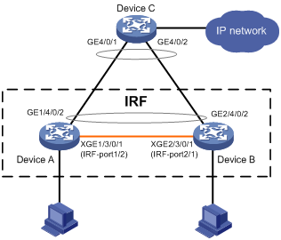
Configuration procedure
1. Identify the master.
<IRF> display irf
Switch Slot Role Priority CPU-Mac Description
*+1 0 Master 1 00e0-fc0a-15e0 DeviceA
1 1 Slave 1 00e0-fc0f-8c02 DeviceA
2 0 Slave 1 00e0-fc0f-15e1 DeviceB
2 1 Slave 1 00e0-fc0f-15e2 DeviceB
--------------------------------------------------
* indicates the device is the master.
+ indicates the device through which the user logs in.
The Bridge MAC of the IRF is: 000f-e26a-58ed
Auto upgrade : no
Mac persistent : always
Domain ID : 0
The output shows that Device A is the master.
2. Examine the configuration for VLAN interfaces.
If a VLAN interface has member ports on different member devices, change the IP address for the VLAN interface on each device to be unique after their operating mode is changed to standalone.
3. Shut down IRF physical ports to disconnect all IRF links. In this example, shut down Ten-Gigabitethernet 1/3/0/1.
<IRF> system-view
[IRF] interface ten-gigabitethernet 1/3/0/1
[IRF-Ten-Gigabitethernet1/3/0/1] shutdown
[IRF-Ten-Gigabitethernet1/3/0/1] quit
4. Save the configuration.
[IRF] save
The current configuration will be written to the device. Are you sure? [Y/N]:y
Please input the file name(*.cfg)[flash:/startup.cfg]
(To leave the existing filename unchanged, press the enter key):
flash:/startup.cfg exists, overwrite? [Y/N]:y
Validating file. Please wait.....................................
The current configuration is saved to the active main board successfully.
Configuration is saved to device successfully.
5. Change the operating mode of Device A to standalone.
[IRF] undo chassis convert mode
The device will switch to stand-alone mode and reboot. You are recommended to save the current running configuration and specify the configuration file for the next startup. Continue? [Y/N]:y
Do you want to convert the content of the next startup configuration file flash:/startup.cfg to make it available in stand-alone mode? [Y/N]:y
Please wait.............
Saving the converted configuration file to main board succeeded.
Chassis 1 Slot 1:
Saving the converted configuration file succeeded.
Now rebooting, please wait...
Device A automatically reboots to complete the operating mode change.
6. Log in to Device B, and change its operating mode to standalone.
<IRF> system-view
[IRF] undo chassis convert mode
The device will switch to stand-alone mode and reboot. You are recommended to save the current running configuration and specify the configuration file for the next startup. Continue? [Y/N]:y
Do you want to convert the content of the next startup configuration file flash:/startup.cfg to make it available in stand-alone mode? [Y/N]:y
Please wait.............
Saving the converted configuration file to main board succeeded.
Chassis 2 Slot 1:
Saving the converted configuration file succeeded.
Now rebooting, please wait...
Device B automatically reboots to complete the operating mode change.
Four-chassis IRF fabric configuration example
Network requirements
As shown in Figure 21, Device A cannot provide enough access bandwidth.
To increase access bandwidth, add three devices and configure them and Device A to form an IRF fabric, as shown in Figure 22.
Configure at least one MAD mechanisms in the IRF fabric.
Figure 21 Network diagram before IRF configuration
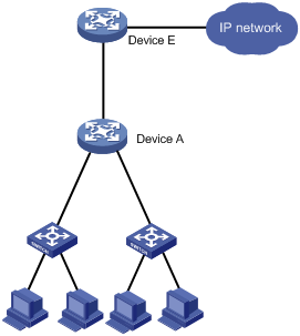
Figure 22 Network diagram for IRF configuration
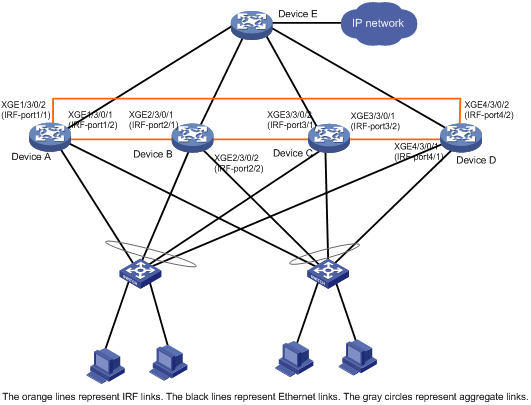
Configuration procedure
1. Configure Device A:
# Set the member ID to 1 and the priority to 12.
<Sysname> system-view
[Sysname] irf member 1
Info: Member ID change will take effect after the switch reboots and operates in IRF mode.
[Sysname] irf priority 12
# Bind Ten-GigabitEthernet 3/0/2 to IRF-port 1.
[Sysname] irf-port 1
[Sysname-irf-port1] port group interface ten-gigabitethernet 3/0/2
[Sysname-irf-port1] quit
[Sysname] interface ten-gigabitethernet 3/0/2
[Sysname-Ten-GigabitEthernet3/0/2] undo shutdown
[Sysname-Ten-GigabitEthernet3/0/2] quit
# Bind Ten-GigabitEthernet 3/0/1 to IRF-port 2.
[Sysname] irf-port 2
[Sysname-irf-port2] port group interface ten-gigabitethernet 3/0/1
[Sysname-irf-port2] quit
[Sysname] interface ten-gigabitethernet 3/0/1
[Sysname-Ten-GigabitEthernet3/0/1] undo shutdown
[Sysname-Ten-GigabitEthernet3/0/1] quit
# Enable enhanced IRF mode.
[Sysname] irf mode enhanced
# Save the configuration to the next-startup configuration file.
[Sysname] save
The current configuration will be written to the device. Are you sure? [Y/N]:y
Please input the file name(*.cfg)[flash:/startup.cfg]
(To leave the existing filename unchanged, press the enter key):
flash:/startup.cfg exists, overwrite? [Y/N]:y
Validating file. Please wait.....................................
The current configuration is saved to the active main board successfully.
Configuration is saved to device successfully
# Enable IRF mode.
<Sysname> system-view
[Sysname] chassis convert mode irf
The device will switch to IRF mode and reboot. You are recommended to save the current running configuration and specify the configuration file for the next startup. Continue? [Y/N]:y
Do you want to convert the content of the next startup configuration file flash:/startup.cfg to make it available in IRF mode? [Y/N]:y
Please wait...
Saving the converted configuration file to the main board succeeded.
Slot 1:
Saving the converted configuration file succeeded.
Now rebooting, please wait...
2. Configure Device B:
# Set the member ID to 2 and the priority to 26.
<Sysname> system-view
[Sysname] irf member 2
Info: Member ID change will take effect after the switch reboots and operates in IRF mode.
[Sysname] irf priority 26
# Bind Ten-GigabitEthernet 3/0/1 to IRF-port 1.
[Sysname] irf-port 1
[Sysname-irf-port1] port group interface ten-gigabitethernet 3/0/1
[Sysname-irf-port1] quit
[Sysname] interface ten-gigabitethernet 3/0/1
[Sysname-Ten-GigabitEthernet3/0/1] undo shutdown
[Sysname-Ten-GigabitEthernet3/0/1] quit
# Bind Ten-GigabitEthernet 3/0/2 to IRF-port 2.
[Sysname] irf-port 2
[Sysname-irf-port2] port group interface ten-gigabitethernet 3/0/2
[Sysname-irf-port2] quit
[Sysname] interface ten-gigabitethernet 3/0/2
[Sysname-Ten-GigabitEthernet3/0/2] undo shutdown
[Sysname-Ten-GigabitEthernet3/0/2] quit
# Enable enhanced IRF mode.
[Sysname] irf mode enhanced
# Save the configuration to the next-startup configuration file.
[Sysname] save
The current configuration will be written to the device. Are you sure? [Y/N]:y
Please input the file name(*.cfg)[flash:/startup.cfg]
(To leave the existing filename unchanged, press the enter key):
flash:/startup.cfg exists, overwrite? [Y/N]:y
Validating file. Please wait.....................................
The current configuration is saved to the active main board successfully.
Configuration is saved to device successfully
# Connect the devices as shown in Figure 22. Log in to Device B.
# Change the operating mode to IRF.
<Sysname> system-view
[Sysname] chassis convert mode irf
The device will switch to IRF mode and reboot. You are recommended to save the current running configuration and specify the configuration file for the next startup. Continue? [Y/N]:y
Do you want to convert the content of the next startup configuration file flash:/startup.cfg to make it available in IRF mode? [Y/N]:y
Please wait...
Saving the converted configuration file to the main board succeeded.
Slot 1:
Saving the converted configuration file succeeded.
Now rebooting, please wait...
Device B reboots to join the IRF fabric.
3. Configure Device C:
# Set the member ID to 3 and the priority to 6.
<Sysname> system-view
[Sysname] irf member 3
Info: Member ID change will take effect after the switch reboots and operates in IRF mode.
[Sysname] irf priority 6
# Bind Ten-GigabitEthernet 3/0/2 to IRF-port 1.
[Sysname] irf-port 1
[Sysname-irf-port1] port group interface ten-gigabitethernet 3/0/2
[Sysname-irf-port1] quit
[Sysname] interface ten-gigabitethernet 3/0/2
[Sysname-Ten-GigabitEthernet3/0/2] undo shutdown
[Sysname-Ten-GigabitEthernet3/0/2] quit
# Bind Ten-GigabitEthernet 3/0/1 to IRF-port 2.
[Sysname] irf-port 2
[Sysname-irf-port2] port group interface ten-gigabitethernet 3/0/1
[Sysname-irf-port2] quit
[Sysname] interface ten-gigabitethernet 3/0/1
[Sysname-Ten-GigabitEthernet3/0/1] undo shutdown
[Sysname-Ten-GigabitEthernet3/0/1] quit
# Enable enhanced IRF mode.
[Sysname] irf mode enhanced
# Save the configuration to the next-startup configuration file.
[Sysname] save
The current configuration will be written to the device. Are you sure? [Y/N]:y
Please input the file name(*.cfg)[flash:/startup.cfg]
(To leave the existing filename unchanged, press the enter key):
flash:/startup.cfg exists, overwrite? [Y/N]:y
Validating file. Please wait.....................................
The current configuration is saved to the active main board successfully.
Configuration is saved to device successfully
# Connect the devices as shown in Figure 22. Log in to Device C.
# Change the operating mode to IRF.
<Sysname> system-view
[Sysname] chassis convert mode irf
The device will switch to IRF mode and reboot. You are recommended to save the current running configuration and specify the configuration file for the next startup. Continue? [Y/N]:y
Do you want to convert the content of the next startup configuration file flash:/startup.cfg to make it available in IRF mode? [Y/N]:y
Please wait...
Saving the converted configuration file to the main board succeeded.
Slot 1:
Saving the converted configuration file succeeded.
Now rebooting, please wait...
Device C reboots to join the IRF fabric.
4. Configure Device D:
# Set the member ID to 4 and the priority to 2.
<Sysname> system-view
[Sysname] irf member 4
Info: Member ID change will take effect after the switch reboots and operates in IRF mode.
[Sysname] irf priority 2
# Bind Ten-GigabitEthernet 3/0/1 to IRF-port 1.
[Sysname] irf-port 1
[Sysname-irf-port1] port group interface ten-gigabitethernet 3/0/1
[Sysname-irf-port1] quit
[Sysname] interface ten-gigabitethernet 3/0/1
[Sysname-Ten-GigabitEthernet3/0/1] undo shutdown
[Sysname-Ten-GigabitEthernet3/0/1] quit
# Bind Ten-GigabitEthernet 3/0/2 to IRF-port 2.
[Sysname] irf-port 2
[Sysname-irf-port2] port group interface ten-gigabitethernet 3/0/2
[Sysname-irf-port2] quit
[Sysname] interface ten-gigabitethernet 3/0/2
[Sysname-Ten-GigabitEthernet3/0/2] undo shutdown
[Sysname-Ten-GigabitEthernet3/0/2] quit
# Enable enhanced IRF mode.
[Sysname] irf mode enhanced
# Save the configuration to the next-startup configuration file.
[Sysname] save
The current configuration will be written to the device. Are you sure? [Y/N]:y
Please input the file name(*.cfg)[flash:/startup.cfg]
(To leave the existing filename unchanged, press the enter key):
flash:/startup.cfg exists, overwrite? [Y/N]:y
Validating file. Please wait.....................................
The current configuration is saved to the active main board successfully.
Configuration is saved to device successfully
# Connect the devices as shown in Figure 22. Log in to Device D.
# Change the operating mode to IRF.
<Sysname> system-view
[Sysname] chassis convert mode irf
The device will switch to IRF mode and reboot. You are recommended to save the current running configuration and specify the configuration file for the next startup. Continue? [Y/N]:y
Do you want to convert the content of the next startup configuration file flash:/startup.cfg to make it available in IRF mode? [Y/N]:y
Please wait...
Saving the converted configuration file to the main board succeeded.
Slot 1:
Saving the converted configuration file succeeded.
Now rebooting, please wait...
Device D reboots to join the IRF fabric. A four-chassis IRF fabric is formed.
5. Configure LACP MAD, BFD MAD, or ARP MAD in the IRF fabric as shown in previous configuration examples.