- Table of Contents
- Related Documents
-
| Title | Size | Download |
|---|---|---|
| 05-MPLS L3VPN Configuration | 1.87 MB |
MPLS L3VPN routing information advertisement
BGP AS number substitution and SoO
MPLS L3VPN configuration task list
Configuring routing between PE and CE
Configuring routing between PEs
Configuring routing features for BGP VPNv4 subaddress family
Configuring and applying policy routing
Configuring a loopback interface
Redistributing the loopback interface route and OSPF routes into BGP
Configuring routing between MCE and VPN site
Configuring routing between MCE and PE
Specifying the VPN label processing mode
Configuring BGP AS number substitution and SoO
Displaying and maintaining MPLS L3VPN
Displaying and maintaining MPLS L3VPN
MPLS L3VPN configuration examples
Configuring MPLS L3VPNs using EBGP between PE and CE
Configuring MPLS L3VPNs using IBGP between PE and CE
Configuring a hub-spoke network
Configuring carrier’s carrier in LDP mode
Configuring carrier’s carrier in BGP mode
Configuring BGP AS number substitution
Configuring BGP AS number substitution and SoO
IPv6 MPLS L3VPN packet forwarding
IPv6 MPLS L3VPN routing information advertisement
IPv6 MPLS L3VPN networking schemes and functions
IPv6 MPLS L3VPN configuration task list
Configuring basic IPv6 MPLS L3VPN
Basic IPv6 MPLS L3VPN configuration task list
Configuring route related attributes for a VPN instance
Configuring routing between PE and CE
Configuring routing between PEs
Configuring routing features for the BGP-VPNv6 subaddress family
Configuring inter-AS IPv6 VPN option A
Configuring inter-AS IPv6 VPN option C
Configuring routing between MCE and VPN site
Configuring routing between MCE and PE
Displaying and maintaining IPv6 MPLS L3VPN
Displaying information about IPv6 MPLS L3VPN
IPv6 MPLS L3VPN configuration examples
Configuring inter-AS IPv6 VPN option A
Configuring inter-AS IPv6 VPN option C
|
|
NOTE: This chapter covers only introduction to and configuration of MPLS L3VPN. For information about MPLS basics, see the chapter “Configuring basic MPLS.” For information about BGP, see Layer 3—IP Routing Configuration Guide. |
MPLS L3VPN overview
Introduction to MPLS L3VPN
MPLS L3VPN is a kind of PE-based L3VPN technology for service provider VPN solutions. It uses BGP to advertise VPN routes and uses MPLS to forward VPN packets on service provider backbones.
MPLS L3VPN is widely used because it provides flexible networking modes, excellent scalability, and convenient support for MPLS QoS and MPLS TE.
The MPLS L3VPN model consists of the following kinds of devices:
· Customer edge (CE) device—A CE resides on a customer network and has one or more interfaces directly connected with service provider networks. It can be a router, a switch, or a host. It neither can "sense" the existence of any VPN nor must it support MPLS.
· Provider edge (PE) device—A PE resides on a service provider network and connects one or more CEs to the network. On an MPLS network, all VPN processing occurs on the PEs.
· Provider (P) device—A P device is a backbone router on a service provider network. It is not directly connected to any CE. It only must be equipped with basic MPLS forwarding capability.
Figure 1 Network diagram for MPLS L3VPN model
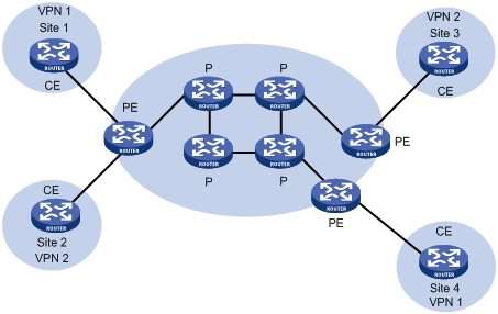
CEs and PEs mark the boundary between the service providers and the customers.
A CE is usually a router. After a CE establishes adjacency with a directly connected PE, it advertises its VPN routes to the PE and learns remote VPN routes from the PE. A CE and a PE use BGP/IGP to exchange routing information. You can also configure static routes between them.
After a PE learns the VPN routing information of a CE, it uses BGP to exchange VPN routing information with other PEs. A PE maintains routing information about only VPNs that are directly connected, rather than all VPN routing information on the provider network.
A P router maintains only routes to PEs. It does not need to know anything about VPN routing information.
When VPN traffic travels over the MPLS backbone, the ingress PE functions as the ingress LSR, the egress PE functions as the egress LSR, while P routers function as the transit LSRs.
MPLS L3VPN concepts
Site
Site is often mentioned in the VPN. Its meanings are described as follows:
· A site is a group of IP systems with IP connectivity that does not rely on any service provider network to implement.
· The classification of a site depends on the topology relationship of the devices, rather than the geographical positions, though the devices at a site are adjacent to each other geographically in most cases.
· The devices at a site can belong to multiple VPNs.
· A site is connected to a provider network through one or more CEs. A site can contain many CEs, but a CE can belong to only one site.
Sites connected to the same provider network can be classified into different sets by policies. Only the sites in the same set can access each other through the provider network. Such a set is called a VPN.
Address space overlapping
Each VPN independently manages the addresses that it uses. The assembly of such addresses for a VPN is called an address space.
The address spaces of VPNs may overlap. For example, if both VPN 1 and VPN 2 use the addresses on network segment 10.110.10.0/24, address space overlapping occurs.
VPN instance
In MPLS VPN, routes of different VPNs are identified by VPN instance.
A PE creates and maintains a separate VPN instance for each VPN at a directly connected site. Each VPN instance contains the VPN membership and routing rules of the corresponding site. If a user at a site belongs to multiple VPNs at the same time, the VPN instance of the site contains information about all the VPNs.
For independency and security of VPN data, each VPN instance on a PE maintains a relatively independent routing table and a separate label forwarding information base (LFIB). VPN instance information contains these items: the LFIB, IP routing table, interfaces bound to the VPN instance, and administration information of the VPN instance. The administration information of the VPN instance includes the route distinguisher (RD), route filtering policy, and member interface list.
VPN-IPv4 address
Traditional BGP cannot process VPN routes which have overlapping address spaces. If, for example, both VPN 1 and VPN 2 use addresses on the subnet 10.110.10.0/24 and each advertise a route to the subnet, BGP selects only one of them, which results in loss of the other route.
PEs use MP-BGP to advertise VPN routes, and use VPN-IPv4 address family to solve the problem with traditional BGP.
A VPN-IPv4 address consists of 12 bytes. The first eight bytes represent the RD, followed by a 4-byte IPv4 address prefix, as shown in Figure 2.
Figure 2 VPN-IPv4 address structure
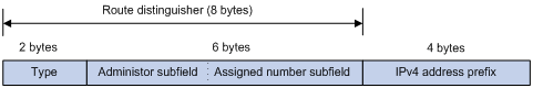
When a PE receives an ordinary IPv4 route from a CE, it must advertise the VPN route to the peer PE. The uniqueness of a VPN route is implemented by adding an RD to the route.
A service provider can independently assign RDs provided the assigned RDs are unique. So, a PE can advertise different routes to VPNs even if the VPNs are from different service providers and are using the same IPv4 address space.
H3C recommends that you configure a distinct RD for each VPN instance on a PE, guaranteeing that routes to the same CE use the same RD. The VPN-IPv4 address with an RD of 0 is in fact a globally unique IPv4 address.
By prefixing a distinct RD to a specific IPv4 address prefix, you get a globally unique VPN IPv4 address prefix.
An RD can be related to an autonomous system (AS) number, in which case it is the combination of the AS number and a discretionary number; or be related to an IP address, in which case it is the combination of the IP address and a discretionary number.
An RD can be in one of the following formats distinguished by the Type field:
· When the value of the Type field is 0, the Administrator subfield occupies two bytes, the Assigned number subfield occupies four bytes, and the RD format is 16-bit AS number:32-bit user-defined number. For example, 100:1.
· When the value of the Type field is 1, the Administrator subfield occupies four bytes, the Assigned number subfield occupies two bytes, and the RD format is 32-bit IPv4 address:16-bit user-defined number. For example, 172.1.1.1:1.
· When the value of the Type field is 2, the Administrator subfield occupies four bytes, the Assigned number subfield occupies two bytes, and the RD format is 32-bit AS number:16-bit user-defined number, where the minimum value of the AS number is 65536. For example, 65536:1.
For the global uniqueness of an RD, do not set the Administrator subfield to any private AS number or private IP address.
BGP extended community attirubtes
· VPN target attributes
MPLS L3VPN uses the BGP extended community attributes called VPN target attributes, or route target attributes, to control the advertisement of VPN routing information.
A VPN instance on a PE supports two types of VPN target attributes:
? Export target attribute—A local PE sets this type of VPN target attribute for VPN-IPv4 routes learned from directly connected sites before advertising them to other PEs.
? Import target attribute—A PE checks the export target attribute of VPN-IPv4 routes advertised by other PEs. If the export target attribute matches the import target attribute of the VPN instance, the PE adds the routes to the VPN routing table.
In other words, VPN target attributes define which sites can receive VPN-IPv4 routes, and from which sites that a PE can receive routes.
Like RDs, VPN target attributes can be the following formats:
? 16-bit AS number:32-bit user-defined number. For example, 100:1.
? 32-bit IPv4 address:16-bit user-defined number. For example, 172.1.1.1:1.
? 32-bit AS number:16-bit user-defined number, where the minimum value of the AS number is 65536. For example, 65536:1.
The Site of Origin (SoO) attribute specifies the site where the route update is originated. It prevents the receiving router from advertising the route update back to the originating site. If the AS-path attribute is lost, the router can use the SoO attribute to avoid routing loops.
The SoO attribute has the following formats:
? 16-bit AS number:32-bit user-defined number. For example, 100:1.
? 32-bit IPv4 address:16-bit user-defined number. For example, 172.1.1.1:1.
? 32-bit AS number:16-bit user-defined number, where the minimum value of the AS number is 65536. For example, 65536:1.
|
|
NOTE: A route update can contain one SoO attribute at most. |
MP-BGP
Multiprotocol extensions for BGP-4 (MP-BGP) advertises VPN composition information and routes between PEs. It is backward compatible and supports both traditional IPv4 address family and other address families, such as VPN-IPv4 address family.
Using MP-BGP can guarantee that private routes of a VPN are advertised only in the VPN and implement communications between MPLS VPN members.
Routing policy
In addition to the import and export extended communities for controlling VPN route advertisement, you can also configure import and export routing policies to control the injection and advertisement of VPN routes more precisely.
An import routing policy can further filter the routes that can be advertised to a VPN instance by using the VPN target attribute of import target attribute. It can reject the routes selected by the communities in the import target attribute. An export routing policy can reject the routes selected by the communities in the export target attribute.
After a VPN instance is created, you can configure import and/or export routing policies as needed.
Tunneling policy
A tunneling policy is used to select the tunnel for the packets of a specific VPN instance to use.
After a VPN instance is created, you can optionally configure a tunneling policy. By default, only one tunnel is selected (no load balancing) in this order: LSP tunnel, CR-LSP tunnel. A tunneling policy takes effect only within the local AS.
MPLS L3VPN packet forwarding
For basic MPLS L3VPN applications in a single AS, VPN packets are forwarded with two layers of labels:
· Layer 1 labels: Outer labels, used for label switching inside the backbone. They indicate LSPs from the local PEs to the remote PEs. Based on layer 1 labels, VPN packets can be label switched along the LSPs to the remote PEs.
· Layer 2 labels: Inner labels, used for forwarding packets from the remote PEs to the CEs. An inner label indicates to which site, or more precisely, to which CE the packet should be sent. A PE finds the interface for forwarding a packet according to the inner label.
If two sites (CEs) belong to the same VPN and are connected to the same PE, each CE only needs to know how to reach the other CE.
The following takes Figure 3 as an example to illustrate the VPN packet forwarding procedure.
Figure 3 VPN packet forwarding
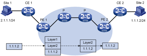
1. Site 1 sends an IP packet with the destination address of 1.1.1.2. CE 1 transmits the packet to PE 1.
2. PE 1 searches VPN instance entries based on the inbound interface and destination address of the packet. Once finding a matching entry, PE 1 labels the packet with both inner and outer labels and forwards the packet out.
3. The MPLS backbone transmits the packet to PE 2 by outer label. The outer label is removed from the packet at the penultimate hop.
4. PE 2 searches VPN instance entries according to the inner label and destination address of the packet to determine the outbound interface and then forwards the packet out the interface to CE 2.
5. CE 2 transmits the packet to the destination by IP forwarding.
MPLS L3VPN networking schemes
In MPLS L3VPNs, VPN target attributes are used to control the advertisement and reception of VPN routes between sites. They work independently and can be configured with multiple values to support flexible VPN access control and implement multiple types of VPN networking schemes.
Basic VPN networking scheme
In the simplest case, all users in a VPN form a closed user group. They can forward traffic to each other but cannot communicate with any user outside the VPN.
For this networking scheme, the basic VPN networking scheme, you need to assign a VPN target to each VPN for identifying the export target attribute and import target attribute of the VPN. Moreover, this VPN target cannot be used by any other VPNs.
Figure 4 Network diagram for basic VPN networking scheme
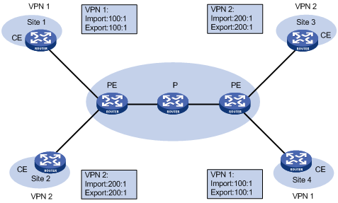
In Figure 4, for example, the VPN target for VPN 1 is 100:1 on the PEs, while that for VPN 2 is 200:1. The two VPN 1 sites can communicate with each other, and the two VPN 2 sites can communicate with each other. However, the VPN 1 sites cannot communicate with the VPN 2 sites.
Hub and spoke networking scheme
For a VPN where a central access control device is required and all users must communicate with each other through the access control device, the hub and spoke networking scheme can be used to implement the monitoring and filtering of user communications.
This networking scheme requires two VPN targets: one for the "hub" and the other for the "spoke".
The VPN target setting rules for VPN instances of all sites on PEs are as follows:
· On spoke PEs (that is, the PEs connected with spoke sites), set the export target attribute to Spoke and the import target attribute to Hub.
· On the hub PE (that is, the PE connected to the hub site), specify two interfaces or subinterfaces, one for receiving routes from spoke PEs, and the other for advertising routes to spoke PEs. Set the import target attribute of the VPN instance for the former to Spoke, and the export target attribute of the VPN instance for the latter to Hub.
Figure 5 Network diagram for hub and spoke networking scheme
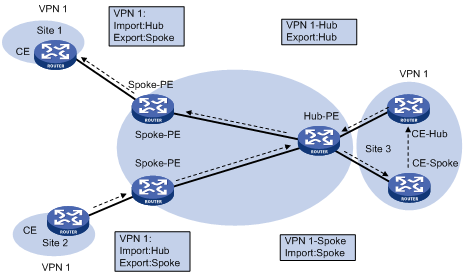
In Figure 5, the spoke sites communicate with each other through the hub site. The arrows in the figure indicate the advertising path of routes from Site 2 to Site 1:
· The hub PE can receive all the VPN-IPv4 routes advertised by spoke PEs.
· All spoke PEs can receive the VPN-IPv4 routes advertised by the hub PE.
· The hub PE advertises the routes learned from a spoke PE to the other spoke PEs. Thus, the spoke sites can communicate with each other through the hub site.
· The import target attribute of any spoke PE is distinct from the export VPN targets of the other spoke PEs. Therefore, any two spoke PEs can neither directly advertise VPN-IPv4 routes to each other nor directly access each other.
Extranet networking scheme
The extranet networking scheme can be used when some resources in a VPN are to be accessed by users that are not in the VPN.
In this kind of networking scheme, if a VPN must access a shared site, the export target attribute and the import target attribute of the VPN must be contained respectively in the import target attribute and the export target attribute of the VPN instance of the shared site.
Figure 6 Network diagram for extranet networking scheme
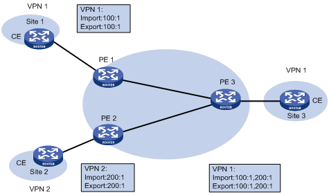
In Figure 6, VPN 1 and VPN 2 can access Site 3 of VPN 1.
· PE 3 can receive the VPN-IPv4 routes advertised by PE 1 and PE 2.
· PE 1 and PE 2 can receive the VPN-IPv4 routes advertised by PE 3.
· Based on the previous, Site 1 and Site 3 of VPN 1 can communicate with each other, and Site 2 of VPN 2 and Site 3 of VPN 1 can communicate with each other.
· PE 3 advertises neither the VPN-IPv4 routes received from PE 1 to PE 2, nor the VPN-IPv4 routes received from PE 2 to PE 1 (that is, route entries learned from an IBGP neighbor will not be advertised to any other IBGP neighbor). Therefore, Site 1 of VPN 1 and Site 2 of VPN 2 cannot communicate with each other.
MPLS L3VPN routing information advertisement
In basic MPLS L3VPN networking, the advertisement of VPN routing information involves CEs and PEs. A P router maintains only the routes of the backbone and does not need to know any VPN routing information. A PE maintains only the routing information of the VPNs directly connected to it, rather than that of all VPNs. Therefore, MPLS L3VPN has excellent scalability.
The VPN routing information of a local CE is advertised in the following phases:
1. Advertised from the local CE to the ingress PE.
2. Advertised from the ingress PE to the egress PE.
3. Advertised from the egress PE to the remote CE.
Then, a route is available between the local CE and the remote CE, and the VPN routing information can be advertised on the backbone.
The following are descriptions of these phases in detail.
Routing information exchange from the local CE to the ingress PE
After establishing an adjacency with the directly connected PE, a CE advertises its VPN routing information to the PE.
The route between the CE and the PE can be a static route, RIP route, OSPF route, IS-IS route, EBGP, or IBGP route. No matter which routing protocol is used, the CE always advertises standard IPv4 routes to the PE.
Routing information exchange from the ingress PE to the egress PE
After learning the VPN routing information from the CE, the ingress PE adds RDs and VPN targets for these standard IPv4 routes to form VPN-IPv4 routes, saves them to the routing table of the VPN instance that is created for the CE, and then triggers MPLS to assign VPN labels for them.
Then, the ingress PE advertises the VPN-IPv4 routes to the egress PE through MP-BGP.
Finally, the egress PE compares the export target attribute of the VPN-IPv4 routes with the import target attribute that it maintains for the VPN instance and determines whether to add the routes to the routing table of the VPN instance.
PEs use IGP to ensure the connectivity between them.
Routing information exchange from the egress PE to the remote CE
A remote CE can learn VPN routes from the egress PE in a number of ways. The routes can be static routes, RIP routes, OSPF routes, IS-IS routes, EBGP routes, and IBGP routes. The exchange of routing information between the egress PE and the remote CE is the same as that between the local CE and the ingress PE.
Inter-AS VPN
In some networking scenarios, multiple sites of a VPN may be connected to multiple ISPs in different ASs, or to multiple ASs of an ISP. Such an application is called inter-AS VPN.
RFC 2547bis presents the following inter-AS VPN solutions:
· VRF-to-VRF—ASBRs manage VPN routes between them through VLAN interfaces. This solution is also called inter-AS option A.
· EBGP advertisement of labeled VPN-IPv4 routes—ASBRs advertise labeled VPN-IPv4 routes to each other through MP-EBGP. This solution is also called inter-AS option B.
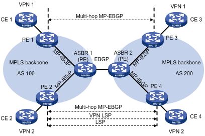
· Multi-hop EBGP advertisement of labeled VPN-IPv4 routes—PEs advertise labeled VPN-IPv4 routes to each other through MP-EBGP. This solution is also called inter-AS option C.
The following describes these solutions.
Inter-AS option A
In this kind of solution, PEs of two ASs are directly connected and each PE is also the ASBR of its AS.
The PEs acting as ASBRs are connected through multiple VLAN interfaces. Each of them treats the other as a CE of its own and advertises IPv4 routes through conventional EBGP. Within an AS, packets are forwarded using two-level label forwarding as VPN packets. Between ASBRs, conventional IP forwarding is used.
Ideally, each inter-AS has a pair of VLAN interfaces to exchange VPN routing information.
Figure 7 Network diagram for inter-AS option A
This kind of solution is easy to carry out because no special configuration is required on the PEs acting as the ASBRs.
However, it has limited scalability because the PEs acting as the ASBRs must manage all the VPN routes and create VPN instances on a per-VPN basis. This leads to excessive VPN-IPv4 routes on the PEs. Moreover, the requirement to create a separate VLAN interface for each VPN also calls for higher performance of the PEs.
Inter-AS option B
In this kind of solution, two ASBRs use MP-EBGP to exchange labeled VPN-IPv4 routes that they have obtained from the PEs in their respective ASs.
As shown in Figure 8, the routes are advertised through the following steps:
1. PEs in AS 100 advertise labeled VPN-IPv4 routes to the ASBR PE of AS 100 or the route reflector (RR) for the ASBR PE through MP-IBGP.
2. The ASBR PE advertises labeled VPN-IPv4 routes to the ASBR PE of AS 200 through MP-EBGP.
3. The ASBR PE of AS 200 advertises labeled VPN-IPv4 routes to PEs in AS 200 or to the RR for the PEs through MP-IBGP.
|
|
NOTE: For information about RR, see Layer 3—IP Routing Configuration Guide. |
The ASBRs must perform the special processing on the labeled VPN-IPv4 routes, which is also called ASBR extension method.
Figure 8 Network diagram for inter-AS option B
In terms of scalability, inter-AS option B is better than option A.
When adopting MP-EBGP method, note the following:
· ASBRs perform no VPN target filtering on VPN-IPv4 routes that they receive from each other. Therefore, the ISPs in different ASs that exchange VPN-IPv4 routes need to agree on the route exchange.
· VPN-IPv4 routes are exchanged only between VPN peers. A VPN user can exchange VPN-IPv4 routes neither with the public network nor with MP-EBGP peers with whom it has not reached agreement on the route exchange.
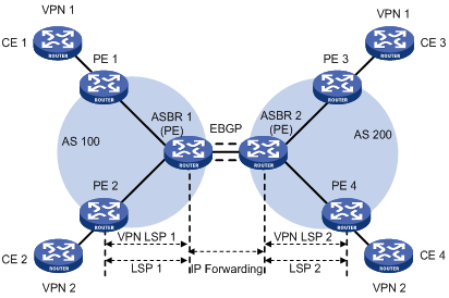
Inter-AS option C
The inter-AS option A and B solutions can satisfy the needs for inter-AS VPNs. However, they require that the ASBRs maintain and advertise VPN-IPv4 routes. When every AS must exchange a great amount of VPN routes, the ASBRs may become bottlenecks hindering network extension.
One way to solve the previous problem is to make PEs directly exchange VPN-IPv4 routes without the participation of ASBRs:
· Two ASBRs advertise labeled IPv4 routes to PEs in their respective ASs through MP-IBGP.
· The ASBRs neither maintain VPN-IPv4 routes nor advertise VPN-IPv4 routes to each other.
· An ASBR maintains labeled IPv4 routes of the PEs in the AS and advertises them to the peers in the other ASs. The ASBR of another AS also advertises labeled IPv4 routes. So, an LSP is established between the ingress PE and egress PE.
· Between PEs of different ASs, Multi-hop EBGP connections are established to exchange VPN-IPv4 routes.
Figure 9 Network diagram for inter-AS option C
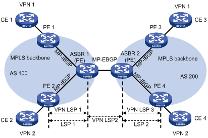
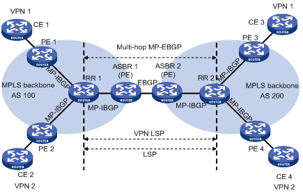
To improve the scalability, you can specify an RR in each AS, making it maintain all VPN-IPv4 routes and exchange VPN-IPv4 routes with PEs in the AS. The RRs in two ASs establish an inter-AS VPNv4 connection to advertise VPN-IPv4 routes, as shown in Figure 10.
Figure 10 Network diagram for inter-AS option C using RRs
Carrier’s carrier
Introduction to carrier's carrier
It is possible that a customer of the MPLS L3VPN service provider is also a service provider. In this case, the MPLS L3VPN service provider is called the provider carrier or the Level 1 carrier, while the customer is called the customer carrier or the Level 2 carrier. This networking model is referred to as carrier’s carrier. In this model, the Level 2 service provider serves as a CE of the Level 1 service provider.
For good scalability, the Level 1 carrier does not redistribute the routes of the customer network connected to a Level 2 carrier; it only redistributes the routes for delivering packets between different sites of the Level 2 carrier. Routes of the customer networks connected to a Level 2 carrier are exchanged through BGP sessions established between the routers of the Level 2 carrier. This can greatly reduce the number of routes maintained by the Level 1 carrier network.
Implementation of carrier’s carrier
Compared with the common MPLS L3VPN, the carrier’s carrier is different because of the way in which a CE of a Level 1 carrier, that is, a Level 2 carrier, accesses a PE of the Level 1 carrier:
· If the PE and the CE are in a same AS, you need to configure IGP and LDP between them.
· If the PE and the CE are not in the same AS, you need to configure MP-EBGP to label the routes exchanged between them.
In either case, you need to enable MPLS on the CE of the Level 1 carrier. Moreover, the CE holds the VPN routes of the Level 2 carrier, but it does not advertise the routes to the PE of the Level 1 carrier; it only exchanges the routes with other PEs of the Level 2 carrier.
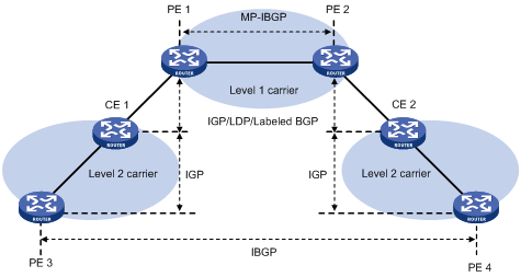
A Level 2 carrier can be an ordinary ISP or an MPLS L3VPN service provider.
When the Level 2 carrier is an ordinary ISP, its PEs run IGP to communicate with the CEs, rather than MPLS. As shown in Figure 11, PE 3 and PE 4 exchange VPN routes of the Level 2 carrier through IBGP sessions.
Figure 11 Scenario where the Level 2 carrier is an ISP
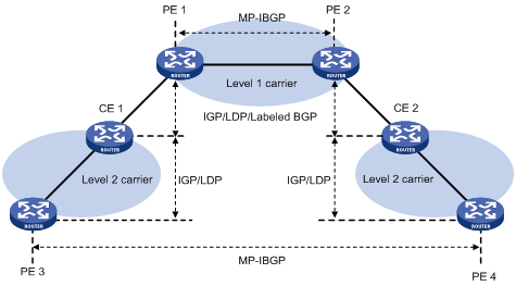
When the Level 2 carrier is an MPLS L3VPN service provider, its PEs must run IGP and LDP to communicate with CEs. As shown in Figure 12, PE 3 and PE 4 exchange VPN routes of the Level 2 carrier through MP-IBGP sessions.
Figure 12 Scenario where the Level 2 carrier is an MPLS L3VPN service provider
|
|
NOTE: If there are equal cost routes between the Level 1 carrier and the Level 2 carrier, H3C recommends establishing equal cost LSPs between them accordingly. |
Nested VPN
Background
In an MPLS L3VPN network, generally a service provider runs an MPLS L3VPN backbone and provides VPN services through PEs. Different sites of a VPN customer are connected to the PEs through CEs to implement communication. In this scenario, a customer’s networks are ordinary IP networks and cannot be further divided into sub-VPNs.
However, in actual applications, customer networks can be dramatically different in form and complexity, and a customer network may need to use VPNs to further group its users. The traditional solution to this request is to implement internal VPN configuration on the service provider’s PEs. This solution is easy to deploy, but it increases the network operation cost and brings issues on management and security because:
· The number of VPNs that PEs must support will increase sharply.
· Any modification of an internal VPN must be done through the service provider.
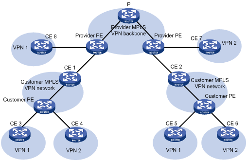
The nested VPN technology offers a better solution. It exchanges VPNv4 routes between PEs and CEs of the ISP MPLS L3VPN and allows a customer to manage its own internal VPNs. Figure 13 depicts a nested VPN network. On the service provider’s MPLS VPN network, there is a customer VPN named VPN A. The customer VPN contains two sub-VPNs, VPN A-1 and VPN A-2. The service provider PEs treat the customer’s network as a common VPN user and do not join any sub-VPNs. The customer’s CE devices (CE 1, CE 2, CE 7 and CE 8) exchange VPNv4 routes that carry the sub-VPN routing information with the service provider PEs, implementing the propagation of the sub-VPN routing information throughout the customer network.
Figure 13 Network diagram for nested VPN
Propagation of routing information
In a nested VPN network, routing information is propagated in the following process:
1. A provider PE and its CEs exchange VPNv4 routes, which carry information about users’ internal VPNs.
2. After receiving a VPNv4 route, a provider PE keeps the user’s internal VPN information, and appends the user’s MPLS VPN attributes on the service provider network. That is, it replaces the RD of the VPNv4 route with the RD of the user’s MPLS VPN on the service provider network and adds the export route-target (ERT) attribute of the user’s MPLS VPN on the service provider network to the extended community attribute list of the route. The internal VPN information of the user is maintained on the provider PE.
3. The provider PE advertises VPNv4 routes which carry the comprehensive VPN information to the other PEs of the service provider.
4. After another provider PE receives the VPNv4 routes, it matches the VPNv4 routes based on its local VPNs. Each local VPN accepts routes of its own and advertises them to its connected sub-VPN CEs (such as CE 3 and CE 4, or CE 5 and CE 6 in Figure 13). If a CE is connected to a provider PE through an IPv4 connection, the PE advertises IPv4 routes to the CE; If a CE is connected to a provider PE through a VPNv4 connection (a user MPLS VPN network), the PE advertises VPNv4 routes to the CE.
Benefits
The nested VPN technology features the following main benefits:
· Support for VPN aggregation. It can aggregate a customer’s internal VPNs into one VPN on the service provider’s MPLS VPN network.
· Support for both symmetric networking and asymmetric networking. Sites of the same VPN can have the same number or different numbers of internal VPNs.
· Support for multiple levels of nesting of internal VPNs.
Nested VPN is flexible and easy to implement and can reduce the cost because a customer only needs to pay for one MPLS VPN to have multiple internal VPNs connected. Nested VPN provides diversified VPN networking methods for a customer, and allows for multi-level hierarchical access control over the internal VPNs.
Multi-role host
The VPN attributes of the packets forwarded from a CE to a PE depend on the VPN instance bound to the inbound interface. Therefore, all CEs whose packets are forwarded through the same inbound interface of a PE must belong to the same VPN.
In a real networking environment, however, a CE may need to access multiple VPNs through a single physical interface. In this case, you can set multiple logical interfaces to satisfy the requirement. But this needs extra configurations and brings limitations to the application.
Using multi-role host, you can configure static routing on the PE to allow packets from the CE to access multiple VPNs.
To allow information from other VPNs to reach the CE from the PE, you must configure static routes on other VPNs that take the interface connected to the CE as the next hop.
|
|
NOTE: All IP addresses associated with the PE must be unique to implement the multi-role host feature. |
In practice, H3C recommends centralizing the addresses of each VPN to improve the forwarding efficiency.
HoVPN
Why HoVPN?
In MPLS L3VPN solutions, PEs are the key devices. They provide two functions:
· User access. This means that the PEs must have a large amount of interfaces.
· VPN route managing and advertising, and user packet processing. These require that a PE must have a large-capacity memory and high forwarding capability.
Most of the current network schemes use the typical hierarchical architecture. For example, the MAN architecture contains typically three layers, namely, the core layer, distribution layer, and access layer. From the core layer to the access layer, the performance requirements on the devices decrease while the network expands.
MPLS L3VPN, on the contrary, is a plane model where performance requirements are the same for all PEs. If a certain PE has limited performance or scalability, the performance or scalability of the whole network is influenced.
Due to the previous difference, you are faced with the scalability problem when deploying PEs at any of the three layers. Therefore, the plane model is not applicable to the large-scale VPN deployment.
To solve the scalability problem of the plane model, MPLS L3VPN must transition to the hierarchical model. In MPLS L3VPN, hierarchy of VPN (HoVPN) was proposed to meet that requirement. With HoVPN, the PE functions can be distributed among multiple PEs, which take different roles for the same functions and form a hierarchical architecture.
As in the typical hierarchical network model, HoVPN has different requirements on the devices at different layers of the hierarchy.
Basic architecture of HoVPN
Figure 14 Basic architecture of HoVPN
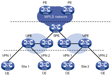
As shown in Figure 14, routers directly connected to CEs are called underlayer PEs (UPEs) or user-end PEs, whereas routers that are connected with UPEs and are in the internal network are called superstratum PEs (SPE) or service provider-end PEs.
The hierarchical PE consists of multiple UPEs and SPEs, which function together as a traditional PE.
|
|
NOTE: With the HoVPN solution, PE functions are implemented hierarchically. Hence, the solution is also called hierarchy of PE (HoPE). |
UPEs and SPEs play the following different roles:
· A UPE allows user access. It maintains the routes of the VPN sites that are directly connected with it, It does not maintain the routes of the remote sites in the VPN, or only maintains their summary routes. A UPE assigns inner labels to the routes of its directly connected sites, and advertises the labels to the SPE along with VPN routes through MP-BGP.
· An SPE manages and advertises VPN routes. It maintains all the routes of the VPNs connected through UPEs, including the routes of both the local and remote sites. An SPE advertises routes along with labels to UPEs, including the default routes of VPN instances or summary routes and the routes permitted by the routing policy. By using routing policies, you can control which nodes in a VPN can communicate with each other.
Different roles mean the following different requirements:
· SPE: An SPE is required to have large-capacity routing table, high forwarding performance, and fewer interface resources.
· UPE: A UPE is required to have small-capacity routing table, low forwarding performance, but higher access capability.
HoVPN takes full use of both the high performance of SPEs and the high access capability of UPEs.
The concepts of SPE and UPE are relative. In the hierarchical PE architecture, a PE may be the SPE of its underlayer PEs and a UPE of its SPE at the same time.
The HoPE and common PEs can coexist in an MPLS network.
SPE-UPE
The MP-BGP running between SPE and UPE can be either MP-IBGP or MP-EBGP. Which one to use depends on whether the UPE and SPE belong to a same AS.
With MP-IBGP, in order to advertise routes between IBGP peers, the SPE acts as the RR and advertises routes from IBGP peer UPE to IBGP peer SPE. However, it does not act as the RR of the other PEs.
Recursion and extension of HoVPN
HoVPN supports HoPE recursion:
· A HoPE can act as a UPE to form a new HoPE with an SPE.
· A HoPE can act as an SPE to form a new HoPE with multiple UPEs.
· HoVPN supports multi-level recursion.
With recursion of HoPEs, a VPN can be extended infinitely in theory.
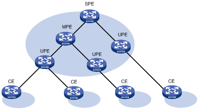
Figure 15 shows a three-level HoPE. The PE in the middle is called the middle-level PE (MPE). MP-BGP runs between SPE and MPE, as well as between MPE and UPE.
|
|
NOTE: The term of MPE does not really exist in a HoVPN model. It is used here just for the convenience of description. |
MP-BGP advertises all the VPN routes of the UPEs to the SPEs, and advertises the default routes of the VPN instance of the SPEs or the VPN routes permitted by the routing policies to the UPEs.
The SPE maintains the VPN routes of all sites in the HoVPN, while each UPE maintains only VPN routes of its directly connected sites. The number of routes maintained by the MPE is between the previous two.
OSPF VPN extension
|
|
NOTE: This section focuses on the OSPF VPN extension. For more information about OSPF, see Layer 3—IP Routing Configuration Guide. |
OSPF for VPNs on a PE
OSPF is a prevalent IGP protocol. It often runs between PE and CE to simplify CE configuration and management because the CEs only need to support OSPF. In addition, if the customers require MPLS L3VPN services through conventional OSPF backbone, using OSPF between PE and CE can simplify the transition.
For OSPF to run between CE and PE, the PE must support multiple OSPF processes. Each OSPF process must correspond to a VPN instance and have its own interface and routing table.
The following describes details of OSPF configuration between PE and CE.
· Configuration of OSPF areas between PE and CE
The OSPF area between a PE and a CE can be either a non-backbone area or a backbone area.
In the OSPF VPN extension application, the MPLS VPN backbone is considered the backbone area (area 0). The area 0 of each VPN site must be connected to the MPLS VPN backbone because OSPF requires that the backbone area be contiguous.
If a VPN site contains an OSPF area 0, the connected PE must be connected to the backbone area of the VPN site through area 0. You can configure a logical connection by using a virtual link.
· BGP/OSPF interaction
PEs advertise VPN routes to each other through BGP and to CEs through OSPF.
Conventional OSPF considers two sites to be in different ASs even if they belong to the same VPN. Therefore, the routes that one site learns are advertised to the other as external routes. This results in more OSPF traffic and network management problems.
The extended OSPF protocol supports multiple instances to address the previous problems. Properly configured, OSPF sites are considered directly connected, and PEs can exchange OSPF routing information as they are using dedicated lines. This improves the network management and makes OSPF applications more effective.
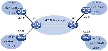
As shown in Figure 16, PE 1 and PE 2 are connected through the MPLS backbone, while CE 11, CE 21, and CE 22 belong to VPN 1. Assumes that CE 11, CE 21, and CE 22 belong to the same OSPF domain. PEs advertise VPN 1 routes in the following procedure:
a. PE 1 redistributes OSPF routes from CE 11 into BGP.
b. PE 1 advertises the VPN routes to PE 2 through BGP.
c. PE 2 redistributes the BGP VPN routes into OSPF and advertises them to CE 21 and CE 22.
Figure 16 Application of OSPF in VPN
With the standard BGP/OSPF interaction, PE 2 advertises the BGP VPN routes to CE 21 and CE 22 through Type 5 LSAs (ASE LSAs). However, CE 11, CE 21, and CE 22 belong to the same OSPF domain, and the route advertisement between them should use Type 3 LSAs (inter-AS routes).
To solve the problem, the PE uses an extended BGP/OSPF interaction process called BGP/OSPF interoperability to advertise routes from one site to another, differentiating the routes from real AS-External routes. The process requires that extended BGP community attributes carry the information for identifying the OSPF attributes.
Each OSPF domain must have a configurable domain ID. H3C recommends that you configure the same domain ID or adopt the default ID for all OSPF processes of the same VPN, so the system can know that all VPN routes with the same domain ID are from the same VPN.
· Routing loop detection
If OSPF runs between CEs and PEs and a VPN site is connected to multiple PEs, when a PE advertises the BGP VPN routes learned from MPLS/BGP to the VPN site through LSAs, the LSAs may be received by another PE, resulting in a routing loop.
To avoid routing loops, when creating Type 3 LSAs, the PE always sets the flag bit DN for BGP VPN routes learned from MPLS/BGP, regardless of whether the PE and the CEs are connected through the OSPF backbone. When performing route calculation, the OSPF process of the PE ignores the Type 3 LSAs whose DN bit is set.
If the PE must advertise to a CE the routes from other OSPF domains, it must indicate that it is the ASBR, and advertise the routes using Type 5 LSAs.
Sham link
Generally, BGP peers carry routing information on the MPLS VPN backbone through the BGP extended community attributes. The OSPF that runs on the remote PE can use the information to create Type 3 summary LSAs to be transmitted to the CEs. As shown in Figure 17, both site 1 and site 2 belong to VPN 1 and OSPF area1. They are connected to different PEs, PE 1 and PE 2. There is an intra-area OSPF link called backdoor link between them. In this case, the route connecting the two sites through PEs is an inter-area route. It is not preferred by OSPF because its preference is lower than that of the intra-area route across the backdoor link.
Figure 17 Network diagram for sham link
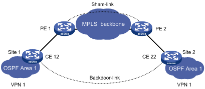
To solve the problem, you can establish a sham link between the two PEs so the routes between them over the MPLS VPN backbone become an intra-area route.
The sham link acts as an intra-area point-to-point link and is advertised through the Type 1 LSA. You can select a route between the sham link and backdoor link by adjusting the metric.
The sham link is considered the link between the two VPN instances with one endpoint address in each VPN instance. The endpoint address is a loopback interface address with a 32-bit mask in the VPN address space on the PE. Different sham links of the same OSPF process can share an endpoint address, but that of different OSPF processes cannot.
BGP advertises the endpoint addresses of sham links as VPN-IPv4 addresses. A route across the sham link cannot be redistributed into BGP as a VPN-IPv4 route.
A sham link can be configured in any area. You need to configure it manually. In addition, the local VPN instance must have a route to the destination of the sham link.
|
|
NOTE: When configuring an OSPF sham link, redistribute OSPF VPN routes to BGP, but do not redistribute BGP routes to OSPF to avoid route loops. |
BGP AS number substitution and SoO
Since BGP detects routing loops by AS number, if EBGP runs between PEs and CEs, you must assign different AS numbers to geographically different sites to ensure correct transmission of the routing information.
The BGP AS number substitution function allows physically dispersed CEs to use the same AS number. The function is a BGP outbound policy and functions on routes to be advertised.
With the BGP AS number substitution function, when a PE advertises a route to a CE of the specified peer, if an AS number identical to that of the CE exist in the AS_PATH of the route, it will be replaced with that of the PE.
|
|
NOTE: After you enable the BGP AS number substitution function, the PE re-advertises all routing information to the connected CEs in the peer group, performing BGP AS number substitution based on the previous principle. |
Figure 18 Application of BGP AS number substitution and SoO
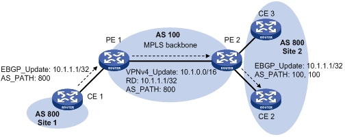
In Figure 18, both Site 1 and Site 2 use the AS number of 800. AS number substitution is enabled on PE 2 for CE 2. Before advertising updates received from CE 1 to CE 2, PE 2 finds that an AS number in the AS_PATH is the same as that of CE 2 and hence substitutes its own AS number 100 for the AS number. In this way, CE 2 can normally receive the routing information from CE 1.
However, the AS number substitution function also introduces a routing loop in Site 2 because route updates originated from CE3 can be advertised back to Site 2 through PE 2 and CE2. To remove the routing loop, you can configure a routing policy on PE2 to add the SoO attribute to route updates received from CE 2 and CE 3 so that PE 2 will not advertise route updates from CE 3 to CE 2.
Multi-VPN-instance CE
Using tunnels, MPLS L3VPN implements private network data transmission over the public network. However, the traditional MPLS L3VPN architecture requires that each VPN instance exclusively use a CE to connect with a PE, as shown in Figure 1.
For better services and higher security, a private network is usually divided into multiple VPNs to isolate services. To meet the requirements, you can configure a CE for each VPN, which increases users’ device expenses and maintenance costs. Or, you can configure multiple VPNs to use the same CE and the same routing table, which cannot ensure the data security.
Using the Multi-VPN-Instance CE (MCE) function of the Ethernet switches, you can remove the contradiction of low cost and high security in multi-VPN networks. With MCE configured, a CE can bind each VPN in a network with a VLAN interface on the CE, and create and maintain a separate routing table (multi-VRF) for each VPN. This separates the forwarding paths of packets of different VPNs and, in conjunction with the PE, can correctly advertise the routes of each VPN to the peer PE, ensuring the normal transmission of VPN packets over the public network.
The following takes the networking illustrated in Figure 19 as an example to introduce how an MCE maintains the routing entries of multiple VPNs and how an MCE exchanges VPN routes with PEs.
Figure 19 Network diagram for the MCE function
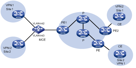
As shown in Figure 19, on the left-side network, there are two VPN sites, both of which are connected to the MPLS backbone through the MCE. VPN 1 and VPN 2 on the left-side network need to establish a tunnel with VPN 1 and VPN 2 on the right-side network respectively.
With the MCE function, you can create a routing table for VPN 1 and VPN 2 respectively on the MCE, and bind VLAN-interface 2 with VPN 1 and VLAN-interface 3 with VPN 2. When receiving a routing message, the MCE can determine the source of the routing information according to the inbound interface, and then update the routing table of the corresponding VPN.
In addition, you need to perform configurations on PE 1 to bind the interface connected to the MCE with the VPNs in the same way as you do on the MCE. The MCE device and PE 1 must be connected through a trunk link to allow packets of VLAN 2 and VLAN 3 to pass through with tags carried. In this way, when receiving a packet, PE 1 can determine which VPN the packet belongs to and then passes the packet to the right tunnel.
You can configure static routes, RIP, OSPF, IS-IS, EBGP, or IBGP between MCE and VPN site and between MCE and PE.
|
|
NOTE: To implement dynamic IP assignment for DHCP clients in private networks, you can configure DHCP server or DHCP relay agent on the MCE. The IP address spaces for different private networks cannot overlap. |
MPLS L3VPN configuration task list
Complete the following tasks to configure MPLS L3VPN:
|
Task |
Remarks |
|
By configuring basic MPLS L3VPN, you can construct simple VPN networks over an MPLS backbone. To deploy special MPLS L3VPN networks, such as inter-AS VPN, nested VPN, and multi-role host, you also need to perform some specific configurations in addition to the basic MPLS L3VPN configuration. For more information, see the related sections. |
|
Configuring basic MPLS L3VPN
The key task in MPLS L3VPN configuration is to manage the advertisement of VPN routes on the MPLS backbone, including PE-CE route exchange and PE-PE route exchange.
Complete the following tasks to configure basic MPLS L3VPN:
|
Task |
Remarks |
|
|
Required |
||
|
Required |
||
|
Optional |
||
|
Optional |
||
|
Optional |
||
|
Required |
||
|
Required |
||
|
Configuring routing features for BGP VPNv4 subaddress family |
Optional |
|
Configuration prerequisites
Before you configure basic MPLS L3VPN, complete the following tasks:
· Configure an IGP for the MPLS backbone (on the PEs and Ps) to ensure IP connectivity
· Configure basic MPLS for the MPLS backbone
· Configure MPLS LDP for the MPLS backbone so that LDP LSPs can be established
Configuring VPN instances
By configuring VPN instances on a PE, you can isolate not only VPN routes from public network routes, but also routes of a VPN from those of another VPN. This feature allows VPN instances to be used in network scenarios besides MPLS L3VPNs.
All VPN instance configurations are performed on PEs or MCEs.
Creating a VPN instance
A VPN instance is associated with a site. It is a collection of the VPN membership and routing rules of its associated site. A VPN instance does not necessarily correspond to one VPN.
When you configure a VPN instance, follow these guidelines:
· The reserved VLAN configuration can take effect only when the system works in standard mode. For more information about system working modes, see Fundamentals Configuration Guide.
· When the system works in standard mode, you must configure a reserved VLAN for a created VPN instance in the following cases: a) the VPN instance is connected with no CEs; b) there is no need to configure the multicast VPN function for the VPN instance; c) there is no need to bind the VPN instance with an IP tunnel.
· To configure a reserved VLAN for a VPN instance, you must configure it before configuring an RD for the VPN instance. Otherwise, the VPN cannot function normally and you must delete the VPN instance, and then re-create the VPN instance in the right configuration order. Before configuring an RD, you cannot configure any other parameters for the VPN instance except a reserved VLAN.
· Do not configure services on a reserved VLAN. Otherwise, the corresponding MPLS L3VPN will be affected, and you must delete the VPN instance, and then re-create the VPN instance in the right configuration order.
· A reserved VLAN does not implement the common VLAN functions, such as VLAN mapping.
· When the system works in standard mode, if a VPN instance is not configured with a reserved VLAN, you cannot configure URPF on the private network VLAN interface bound with the VPN instance.
· Once established, the association between a VPN instance and its reserved VLAN cannot be removed. To modify the association, you need to delete the VPN instance, recreate it, and then specify another reserved VLAN for it.
To create and configure a VPN instance:
|
Step |
Command |
Remarks |
|
1. Enter system view. |
system-view |
N/A |
|
2. Create a VPN instance and enter VPN instance view. |
ip vpn-instance vpn-instance-name |
N/A |
|
3. Specify a reserved VLAN for the VPN instance. |
reserve-vlan vlan-id |
N/A |
|
4. Configure an RD for the VPN instance. |
route-distinguisher route-distinguisher |
A VPN instance takes effect only after you configure an RD for it. |
|
5. Configure a description for the VPN instance. |
description text |
Optional. The description should contain the VPN instance’s related information, such as its relationship with a certain VPN. |
Associating a VPN instance with an interface
After creating and configuring a VPN instance, you need to associate the VPN instance with the interface for connecting the CE. Any LDP-capable interface can be associated with a VPN instance. For information about LDP-capable interfaces, see the chapter “Configuring basic MPLS.”
To associate a VPN instance with an interface:
|
Step |
Command |
Remarks |
|
1. Enter system view. |
system-view |
N/A |
|
2. Enter interface view. |
interface interface-type interface-number |
N/A |
|
3. Associate a VPN instance with the interface. |
ip binding vpn-instance vpn-instance-name |
No VPN instance is associated with an interface by default. |
|
|
NOTE: The ip binding vpn-instance command clears the IP address of the interface on which it is configured. Be sure to re-configure an IP address for the interface after configuring the command. |
Configuring route related attributes for a VPN instance
The control process of VPN route advertisement is as follows:
· When a VPN route learned from a CE gets redistributed into BGP, BGP associates it with a VPN target extended community attribute list, which is usually the export target attribute of the VPN instance associated with the CE.
· The VPN instance determines which routes it can accept and redistribute according to the import-extcommunity in the VPN target.
· The VPN instance determines how to change the VPN targets attributes for routes to be advertised according to the export-extcommunity in the VPN target.
To configure route related attributes for a VPN instance:
|
Step |
Command |
Remarks |
|
1. Enter system view. |
system-view |
N/A |
|
2. Enter VPN instance view. |
ip vpn-instance vpn-instance-name |
N/A |
|
3. Enter IPv4 VPN view. |
ipv4-family |
Optional. |
|
4. Configure VPN targets. |
vpn-target vpn-target&<1-8> [ both | export-extcommunity | import-extcommunity ] |
N/A |
|
5. Set the maximum number of routes allowed. |
routing-table limit number { warn-threshold | simply-alert } |
Optional. |
|
6. Apply an import routing policy. |
import route-policy route-policy |
Optional. By default, all routes matching the import target attribute are accepted. |
|
7. Apply an export routing policy. |
export route-policy route-policy |
Optional. By default, routes to be advertised are not filtered. |
|
|
NOTE: · Route related attributes configured in VPN instance view are applicable to both IPv4 VPNs and IPv6 VPNs. · You can configure route related attributes for IPv4 VPNs in both VPN instance view and IPv4 VPN view. Those configured in IPv4 VPN view take precedence. · A single vpn-target command can configure up to eight VPN targets. You can configure up to 64 VPN targets for a VPN instance. · You can define the maximum number of routes for a VPN instance to support, preventing too many routes from being redistributed into the PE. · The routing policy associated with a VPN instance must have been configured. Otherwise route filtering does not take effect. |
Configuring a tunneling policy for a VPN instance
When multiple tunnels exist in an MPLS L3VPN network, you can configure a tunneling policy to specify the type and number of tunnels to be used by using the tunnel select-seq command or the preferred-path command.
With the tunnel select-seq command, you can specify the tunnel selection preference order and the number of tunnels for load balancing.
With the preferred-path command, you can configure preferred tunnels that each correspond to a tunnel interface.
After a tunneling policy is applied on a PE, the PE selects tunnels in this order:
· The PE matches the peer PE address against the destination addresses of preferred tunnels, starting from the tunnel with the smallest number. If no match is found, the local PE selects tunnels as configured by the tunnel select-seq command or the default tunneling policy if the tunnel select-seq command is not configured. The default tunneling policy selects only one tunnel (no load balancing) in this order: LSP tunnel, CR-LSP tunnel.
· If a matching tunnel is found and the tunnel is available, the local PE stops matching other tunnels and forwards the traffic to the specified tunnel interface.
· If the matching tunnel is unavailable (for example, the tunnel is down or the tunnel’s ACL does not permit the traffic) and is not specified with the disable-fallback keyword, the local PE continues to match other preferred tunnels; if the tunnel is specified with the disable-fallback keyword, the local PE stops matching and tunnel selection fails.
To configure a tunneling policy for a VPN instance:
|
Step |
Command |
Remarks |
|
1. Enter system view. |
system-view |
N/A |
|
2. Create a tunneling policy and enter tunneling policy view. |
tunnel-policy tunnel-policy-name |
N/A |
|
3. Configure a preferred tunnel and specify a tunnel interface for it. |
preferred-path number interface tunnel tunnel-number [ disable-fallback ] |
Optional. By default, no preferred tunnel is configured. |
|
4. Specify the tunnel selection preference order and the number of tunnels for load balancing. |
tunnel select-seq { cr-lsp | lsp } * load-balance-number number |
Optional. By default, only one tunnel is selected (no load balancing) in this order: LSP tunnel, CR-LSP tunnel. |
|
5. Return to system view. |
quit |
N/A |
|
6. Enter VPN instance view. |
ip vpn-instance vpn-instance-name |
N/A |
|
7. Enter IPv4 VPN view. |
ipv4-family |
Optional. |
|
8. Apply the tunnel policy to the VPN instance. |
tnl-policy tunnel-policy-name |
By default, only one tunnel is selected (no load balancing) in this order: LSP tunnel, CR-LSP tunnel. |
|
|
NOTE: · In a tunneling policy, you can configure up to 64 preferred tunnels. The tunnel interfaces specified for the preferred tunnels can have the same destination address and the tunnel encapsulation type must be MPLS TE. · When you configure the tunnel selection preference order by using the tunnel select-seq command, a tunnel type closer to the select-seq keyword has a higher priority. For example, with the tunnel select-seq cr-lsp lsp load-balance-number 1 command configured, VPN uses an LSP tunnel when no CR-LSP exists. After a CR-LSP is created, the VPN uses the CR-LSP tunnel instead. · A tunneling policy configured in VPN instance view is applicable to both IPv4 VPNs and IPv6 VPNs. · You can configure a tunneling policy for IPv4 VPNs in both VPN instance view and IPv4 VPN view. A tunneling policy configured in IPv4 VPN view takes precedence. · Create a tunneling policy before associating it with a VPN instance. Otherwise, the default tunneling policy is used. The default tunneling policy selects only one tunnel (no load balancing) in this order: LSP tunnel, CR-LSP tunnel. |
Configuring an LDP instance
LDP instances are for carrier’s carrier network applications.
This task is to configure the LDP capability for an existing VPN instance, create an LDP instance for the VPN instance, and configure LDP parameters for the LDP instance.
To configure an LDP instance:
|
Step |
Command |
Remarks |
|
1. Enter system view. |
system-view |
N/A |
|
2. Enable LDP for a VPN instance, create an LDP instance, and enter MPLS LDP VPN instance view. |
mpls ldp vpn-instance vpn-instance-name |
Disabled by default. |
|
3. Configure LDP parameters except LDP GR for the instance. |
For configuration information, see the chapter “Configuring basic MPLS.” |
Optional. |
|
|
NOTE: · Except the command for LDP GR, all commands available in MPLS LDP view can be configured in MPLS LDP VPN instance view. For more information about MPLS LDP, see the chapter “Configuring basic MPLS.” · Configurations in MPLS LDP VPN instance view affect only the LDP-enabled interface bound to the VPN instance, while configurations in MPLS LDP view do not affect interfaces bound to VPN instances. When configuring the transport address of an LDP instance, you need to use the IP address of the interface bound to the VPN instance. · By default, LDP adjacencies on a private network are established by using addresses of the LDP-enabled interfaces, while those on the public network are established by using the LDP LSR ID. |
Configuring routing between PE and CE
You can configure static routing, RIP, OSPF, IS-IS, EBGP, or IBGP between PE and CE.
Configuration prerequisites
Before you configure routing between PE and CE, complete the following tasks:
· Assign an IP address to the CE-PE interface of the CE.
· Assign an IP address to the PE-CE interface of the PE.
Configuring static routing between PE and CE
To configure static routing between PE and CE:
|
Step |
Command |
Remarks |
|
1. Enter system view. |
system-view |
N/A |
|
2. Configure a static route for a VPN instance. |
·
Approach 1: ·
Approach 2: |
Use either approach as needed. Perform this configuration on PEs. On CEs, configure normal static routes. |
|
|
NOTE: For information about static routing, see Layer 3—IP Routing Configuration Guide. |
Configuring RIP between PE and CE
A RIP process belongs to the public network or a single VPN instance. If you create a RIP process without binding it to a VPN instance, the process belongs to the public network.
To configure RIP between PE and CE:
|
Step |
Command |
Remarks |
|
1. Enter system view. |
system-view |
N/A |
|
2. Create a RIP process for a VPN instance and enter RIP view. |
rip [ process-id ] vpn-instance vpn-instance-name |
Perform this configuration on PEs. On CEs, create a normal RIP process. |
|
3. Enable RIP on the interface attached to the specified network. |
network network-address |
By default, RIP is disabled on an interface. |
|
|
NOTE: For more information about RIP, see Layer 3—IP Routing Configuration Guide. |
Configuring OSPF between PE and CE
An OSPF process that is bound to a VPN instance does not use the public network router ID configured in system view. Therefore, you must specify the router ID when starting a process or to configure the IP address for at least one interface of the VPN instance.
An OSPF process belongs to the public network or a single VPN instance. If you create an OSPF process without binding it to a VPN instance, the process belongs to the public network.
To configure OSPF between PE and CE:
|
Step |
Command |
Remarks |
|
1. Enter system view. |
system-view |
N/A |
|
2. Create an OSPF process for a VPN instance and enter the OSPF view. |
ospf [ process-id | router-id router-id | vpn-instance vpn-instance-name ] * |
Perform the configurations on PEs. On CEs, create a normal OSPF process. |
|
3. Configure the OSPF domain ID. |
domain-id domain-id [ secondary ] |
Optional. 0 by default |
|
4. Configure the type codes of OSPF extended community attributes. |
ext-community-type { domain-id type-code1 | router-id type-code2 | route-type type-code3 } |
Optional. The defaults are as follows: 0x0005 for Domain ID, 0x0107 for Router ID, and 0x0306 for Route Type. Perform this configuration on PEs. |
|
5. Create an OSPF area and enter area view. |
area area-id |
By default, no OSPF area is created. |
|
6. Enable OSPF on the interface attached to the specified network in the area. |
network ip-address wildcard-mask |
By default, an interface neither belongs to any area nor runs OSPF. |
|
|
NOTE: Deleting a VPN instance also deletes all the related OSPF processes. |
An OSPF process can be configured with only one domain ID. Domain IDs of different OSPF processes are independent of each other.
All OSPF processes of a VPN must be configured with the same domain ID for routes to be correctly advertised, while OSPF processes on PEs in different VPNs can be configured with domain IDs as desired.
The domain ID of an OSPF process is included in the routes generated by the process. When an OSPF route is redistributed into BGP, the OSPF domain ID is included in the BGP VPN route and delivered as a BGP extended community attribute.
|
|
NOTE: For more information about OSPF, see Layer 3—IP Routing Configuration Guide. |
Configuring IS-IS between PE and CE
An IS-IS process belongs to the public network or a single VPN instance. If you create an IS-IS process without binding it to a VPN instance, the process belongs to the public network.
To configure IS-IS between PE and CE:
|
Step |
Command |
Remarks |
|
1. Enter system view. |
system-view |
N/A |
|
2. Create an IS-IS process for a VPN instance and enter IS-IS view. |
isis [ process-id ] vpn-instance vpn-instance-name |
N/A |
|
3. Configure a network entity title for the IS-IS process. |
network-entity net |
Not configured by default |
|
4. Return to system view. |
quit |
N/A |
|
5. Enter interface view. |
interface interface-type interface-number |
N/A |
|
6. Enable the IS-IS process on the interface. |
isis enable [ process-id ] |
Disabled by default |
|
|
NOTE: For more information about IS-IS, see Layer 3—IP Routing Configuration Guide. |
Configuring EBGP between PE and CE
1. Configure the PE
To configure the PE:
|
Step |
Command |
Remarks |
|
1. Enter system view. |
system-view |
N/A |
|
2. Enable BGP and enter BGP view. |
bgp as-number |
N/A |
|
3. Enter BGP VPN instance view. |
ipv4-family vpn-instance vpn-instance-name |
N/A |
|
4. Configure the CE as the VPN EBGP peer. |
peer { group-name | ip-address } as-number as-number |
N/A |
|
5. Redistribute the routes of the local CEs. |
import-route protocol [ process-id ] [ med med-value | route-policy route-policy-name ] * |
A PE must redistribute the routes of the local CEs into its VPN routing table so it can advertise them to the peer PE. |
|
6. Configure BGP to filter routes to be advertised. |
filter-policy { acl-number | ip-prefix ip-prefix-name } export [ direct | isis process-id | ospf process-id | rip process-id | static ] |
Optional. By default, BGP does not filter routes to be advertised. |
|
7. Configure BGP to filter received routes. |
filter-policy { acl-number | ip-prefix ip-prefix-name } import |
Optional. By default, BGP does not filter received routes. |
|
8. Allow the local AS number to appear in the AS_PATH attribute of a received route and set the maximum number of repetitions. |
peer { group-name | ip-address } allow-as-loop [ number ] |
Optional. For the hub and spoke network scheme |
|
|
NOTE: Normally, BGP detects routing loops by AS number. In the hub and spoke network scheme, however, with EBGP running between PE and CE, the routing information the PE advertises to a CE carries the number of the AS where the PE resides. Therefore, the route updates that the PE receives from the CE also include the number of the AS where the PE resides. This causes the PE unable to receive the route updates. In this case, routing loops must be allowed. |
2. Configure the CE
To configure the CE:
|
Step |
Command |
Remarks |
|
1. Enter system view. |
system-view |
N/A |
|
2. Enter BGP view. |
bgp as-number |
N/A |
|
3. Configure the PE as the EBGP peer. |
peer { group-name | ip-address } as-number as-number |
N/A |
|
4. Configure the route redistribution and advertisement behavior. |
import-route protocol [ process-id ] [ med med-value | route-policy route-policy-name ] * |
Optional. A CE must advertise its routes to the connected PE so the PE can advertise them to the peer CE. |
|
|
NOTE: · Exchange of BGP routes for a VPN instance is the same as that of ordinary BGP routes. · The BGP configuration task in BGP-VPN instance view is the same as that in BGP view. For more information, see Layer 3—IP Routing Configuration Guide. · For information about BGP peer and peer group configuration, see Layer 3—IP Routing Configuration Guide. This chapter does not differentiate between peer and peer group. |
Configuring IBGP between PE and CE
|
|
NOTE: IBGP can be used between PE and CE devices in only common MPLS L3VPN networks. In networks such as Extranet, inter-AS VPN, carrier’s carrier, nested VPN, and HoVPN, you cannot use IBGP between PE and CE devices. |
1. Configure the PE
To configure IBGP between PE and CE:
|
Step |
Command |
Remarks |
|
1. Enter system view. |
system-view |
N/A |
|
2. Enter BGP view. |
bgp as-number |
N/A |
|
3. Enter BGP VPN instance view. |
ipv4-family vpn-instance vpn-instance-name |
N/A |
|
4. Configure the CE as the VPN IBGP peer. |
peer { group-name | ip-address } as-number as-number |
N/A |
|
5. Configure the system to be the RR and specify the CE as the client of the RR. |
peer { group-name | ip-address } reflect-client |
Optional. By default, no RR or RR client is configured. |
|
6. Enable route reflection between clients. |
reflect between-clients |
Optional. Enabled by default. If the clients are fully meshed, you do not need to enable route reflection. |
|
7. Configure the cluster ID for the RR. |
reflector cluster-id { cluster-id | ip-address } |
Optional. By default, each RR in a cluster uses its own router ID as the cluster ID. If more than one RR exists in a cluster, use this command to configure the same cluster ID for all RRs in the cluster to avoid routing loops. |
|
8. Configure BGP to filter routes to be advertised. |
filter-policy { acl-number | ip-prefix ip-prefix-name } export [ direct | isis process-id | ospf process-id | rip process-id | static ] |
Optional. By default, BGP does not filter routes to be advertised. |
|
9. Configure BGP to filter received routes. |
filter-policy { acl-number | ip-prefix ip-prefix-name } import |
Optional. By default, BGP does not filter received routes. |
|
|
NOTE: · By default, a PE does not advertise routes learned from IBGP peer CEs to IBGP peers, including VPNv4 IBGP peers. Only when you configure an IBGP peer CE as a client of the RR, does the PE advertise routes learned from it to other IBGP peers. · You can execute the reflect between-clients command and the reflector cluster-id command in multiple views, such as BGP-VPN instance view and BGP-VPNv4 subaddress family view. The two commands take effect for only the RR in the view where they are executed. For RRs in other views, they do not take effect. · Configuring an RR does not change the next hop of a route. To change the next hop of a route, configure an inbound policy on the receiving side of the route. |
2. Configure the CE
To configure the CE:
|
Step |
Command |
Remarks |
|
1. Enter system view. |
system-view |
N/A |
|
2. Enter BGP view. |
bgp as-number |
N/A |
|
3. Configure the PE as the IBGP peer. |
peer { group-name | ip-address } as-number as-number |
N/A |
|
4. Configure route redistribution. |
import-route protocol [ process-id ] [ med med-value | route-policy route-policy-name ] * |
Optional. A CE must advertise its routes to the connected PE so that the PE can advertise them to the peer CE. |
|
|
NOTE: · Exchange of BGP routes of a VPN instance is the same as that of ordinary BGP routes. · The BGP configuration task in BGP VPN instance view is the same as that in BGP view. For more information, see Layer 3—IP Routing Configuration Guide. · For information about BGP peer and BGP peer group configuration, see Layer 3—IP Routing Configuration Guide. This chapter does not differentiate between peer and peer group. |
Configuring routing between PEs
Perform the following configurations on PEs.
To configure routing between PEs:
|
Step |
Command |
Remarks |
|
1. Enter system view. |
system-view |
N/A |
|
2. Enter BGP view. |
bgp as-number |
N/A |
|
3. Configure the remote PE as the peer. |
peer { group-name | ip-address } as-number as-number |
N/A |
|
4. Specify the source interface for route updates. |
peer { group-name | ip-address } connect-interface interface-type interface-number |
By default, BGP uses the source interface of the optimal route update packet. |
|
5. Enter BGP-VPNv4 subaddress family view. |
ipv4-family vpnv4 |
N/A |
|
6. Enable the exchange of BGP-VPNv4 routing information with the specified peer. |
peer { group-name | ip-address } enable |
By default, BGP peers exchange IPv4 routing information only. |
Configuring routing features for BGP VPNv4 subaddress family
With BGP VPNv4 subaddress family, there are a variety of routing features that are the same as those for BGP IPv4 unicast routing. You can select any of the features as required.
Configuring common routing features for all types of subaddress families
For VPN applications, BGP address families include BGP VPN-IPv4 address family, and VPLS address family. Every command in the following table has the same function on BGP routes for each type of the address families and only takes effect for the BGP routes in the address family view where the command is executed.
To configure common routing features for all types of subaddress families:
|
Step |
Command |
Remarks |
|
1. Enter system view. |
system-view |
N/A |
|
2. Enter BGP view. |
bgp as-number |
N/A |
|
3. Configure the remote PE as the peer. |
peer ip-address as-number as-number |
N/A |
|
4. Specify the interface for TCP connection. |
peer ip-address connect-interface interface-type interface-number |
N/A |
|
5. Enter address family view. |
· ipv4-family vpnv4 · vpls-family |
Use either command as needed. |
|
6. Allow the local AS number to appear in the AS_PATH attribute of a received route and set the maximum number of repetitions. |
peer { group-name | ip-address } allow-as-loop [ number ] |
Optional. |
|
7. Enable a peer or peer group for an address family and enable the exchange of BGP routing information of the address family. |
peer { group-name | ip-address } enable |
By default, only IPv4 routing information is exchanged between BGP peers. |
|
8. Add a peer into an existing peer group. |
peer ip-address group group-name |
Optional. |
|
9. Configure the system to use the local address as the next hop of a route to be advertised to a specific peer or peer group. |
peer { group-name | ip-address } next-hop-local |
Optional. By default, the system uses the local address as the next hop of a route to be advertised to an EBGP peer. In the inter-AS option C solution, you must configure the peer { group-name | ip-address } next-hop-invariable command on the RR for multi-hop EBGP neighbors and reflector clients to make sure that the next hop of a VPN route will not be changed. |
|
10. Configure the system to be the RR and set a peer or peer group as the client of the RR. |
peer { group-name | ip-address } reflect-client |
Optional. By default, no RR or RR client is configured. |
|
11. Enable the Outbound Route Filtering (ORF) capability for a BGP peer or peer group. |
peer { group-name | ip-address } capability-advertise orf ip-prefix { both | receive | send } |
Optional. By default, the ORF capability is disabled on a BGP peer or peer group. |
|
12. Enable VPN target filtering for received VPNv4 routes. |
policy vpn-target |
Optional. Enabled by default. |
|
13. Enable route reflection between clients. |
reflect between-clients |
Optional. Enabled by default. |
|
14. Specify the cluster ID of the RR. |
reflector cluster-id { cluster-id | ip-address } |
Optional. Router ID of an RR in the cluster by default. |
|
15. Create an RR reflection policy. |
rr-filter extended-community-list-number |
Optional. By default, an RR does not filter the reflected routes. With an RR reflection policy, only IBGP routes whose Extended Communities attribute matches the specified one are reflected. By configuring different RR reflection policies on different RRs, you can implement load balancing among the RRs. |
|
|
NOTE: For information about VPLS address family, see MPLS Command Reference. |
Configuring specific routing features for BGP-VPNv4 subaddress family
To configure specific routing features for BGP-VPNv4 subaddress family:
|
Step |
Command |
Remarks |
|
1. Enter system view. |
system-view |
N/A |
|
2. Enter BGP view. |
bgp as-number |
N/A |
|
3. Configure the remote PE as the peer. |
peer ip-address as-number as-number |
N/A |
|
4. Specify the interface for TCP connection. |
peer ip-address connect-interface interface-type interface-number |
N/A |
|
5. Enter BGP-VPNv4 subaddress family view. |
ipv4-family vpnv4 |
N/A |
|
6. Set the default value of the local preference. |
default local-preference value |
Optional. 100 by default. |
|
7. Set the default value for the system MED. |
default med med-value |
Optional. By default, the default value of the system MED is 0. |
|
8. Filter all or certain types of routes to be advertised. |
filter-policy { acl-number | ip-prefix ip-prefix-name } export [ direct | isis process-id | ospf process-id | rip process-id | static ] |
Optional. By default, BGP does not filter routes to be advertised. |
|
9. Filter received routes. |
filter-policy { acl-number | ip-prefix ip-prefix-name } import |
Optional. By default, BGP does not filter received routes. |
|
10. Advertise community attributes to a peer or peer group. |
peer { group-name | ip-address } advertise-community |
Optional. By default, no community attributes are advertised to any peer or peer group. |
|
11. Filter routes received from or to be advertised to a peer or peer group based on an AS_PATH list. |
peer { group-name | ip-address } as-path-acl aspath-filter-number { import | export } |
Optional. By default, no AS filtering list is applied to a peer or peer group. |
|
12. Advertise a default VPN route to a peer or peer group. |
peer { group-name | ip-address } default-route-advertise vpn-instance vpn-instance-name |
Optional. By default, no default VPN route is advertised to a peer or peer group. |
|
13. Apply a filtering policy to a peer or peer group. |
peer { group-name | ip-address } filter-policy acl-number { export | import } |
Optional. By default, no filtering policy is applied to a peer or peer group. |
|
14. Apply a route filtering policy based on IP prefix list to a peer or peer group. |
peer { group-name | ip-address } ip-prefix prefix-name { export | import } |
Optional. By default, no route filtering policy based on IP prefix list is applied to a peer or peer group. |
|
15. Specify not to change the next hop of a route when advertising it to an EBGP peer. |
peer { group-name | ip-address } next-hop-invariable |
Optional. By default, a device uses its address as the next hop when advertising a route to its EBGP peer. |
|
16. Specify the preference value for the routes received from the peer or peer group. |
peer { group-name | ip-address } preferred-value value |
Optional. 0 by default. |
|
17. Make BGP updates to be sent carry no private AS numbers. |
peer { group-name | ip-address } public-as-only |
Optional. By default, a BGP update carries private AS numbers. |
|
18. Apply a routing policy to a peer or peer group. |
peer { group-name | ip-address } route-policy route-policy-name { export | import } |
Optional. By default, no routing policy is applied to a peer or peer group. |
|
|
NOTE: For information about BGP routing, see Layer 3—IP Routing Configuration Guide. |
Configuring inter-AS VPN
If the MPLS backbone on which the VPN routes rely spans multiple ASs, you must configure inter-AS VPN.
There are three inter-AS VPN solutions. You can choose them as required.
Configuration prerequisites
Before configuring multi-provider VPN, complete the following tasks:
· Configure an IGP for the MPLS backbones in each AS to implement IP connectivity of the backbones in the AS
· Configure basic MPLS capabilities for the MPLS backbones of each AS
· Configure MPLS LDP for the MPLS backbones so that LDP LSPs can be established
· Configure basic MPLS L3VPN for each AS
|
|
NOTE: When configuring basic MPLS L3VPN for each AS, specific configurations may be required on PEs or ASBR-PEs. This depends on the inter-AS VPN solution selected. |
Configuring inter-AS option A
Inter-AS option A applies to scenarios where the number of VPNs and that of VPN routes on the PEs are relatively small. It is simple to implement.
To configure inter-AS option A, you only need to do the following:
· Configure basic MPLS L3VPN on each AS.
· Configure each ASBR, taking the peer ASBR PE as its CE.
In other words, configure VPN instances for PEs and ASBR PEs respectively. The VPN instance for PE is used to allow CEs to access the network, while that for ASBR-PE is used to access its peer ASBR-PE.
For more information, see “Configuring basic MPLS L3VPN.”
|
|
NOTE: In the inter-AS option A solution, for the same VPN, the VPN targets configured on the PEs must match those configured on the ASBR-PEs in the same AS to make sure that VPN routes sent by the PEs (or ASBR-PEs) can be received by the ASBR-PEs (or PEs). VPN targets configured on the PEs in different ASs do not have such requirements. |
Configuring inter-AS option B
To configure inter-AS option B on ASBR PEs:
|
Step |
Command |
Remarks |
|
1. Enter system view. |
system-view |
N/A |
|
2. Enter interface view for the interface connecting to the remote ASBR-PE. |
interface interface-type interface-number |
N/A |
|
3. Configure the IP address of the interface. |
ip address ip-address { mask | mask-length } |
N/A |
|
4. Return to system view. |
quit |
N/A |
|
5. Enter BGP view. |
bgp as-number |
N/A |
|
6. Enter BGP-VPNv4 subaddress family view. |
ipv4-family vpnv4 |
N/A |
|
7. Disable VPN target filtering for VPNv4 routes. |
undo policy vpn-target |
By default, PE performs VPN target filtering of the received VPNv4 routes. The routes surviving the filtering will be added to the routing table, and the others are discarded. |
In the inter-AS option B solution, the ASBR PEs must maintain all VPNv4 routing information and advertise the information to peer ASBR PEs. In this case, the ASBR PEs must receive all VPNv4 routing information without performing VPN target based filtering.
|
|
NOTE: In the inter-AS option B solution, for the same VPN, the VPN targets for the VPN instances on the PEs in different ASs must match. |
|
|
CAUTION: For inter-AS option B, the following configuration methods are available: · Do not change the next hop on an ASBR. With this method, you still need to configure MPLS LDP between ASBRs. · Change the next hop on an ASBR. With this method, MPLS LDP is not required between ASBRs. The switch supports only the second method. Therefore, MP-EBGP routes will get their next hops changed by default before being redistributed to MP-IBGP. However, normal EBGP routes to be advertised to IBGP do not have their next hops changed by default. To change the next hops to local addresses, use the peer { ip-address | group-name } next-hop-local command. For information about the command, see Layer 3—IP Routing Configuration Guide. |
Configuring inter-AS option C
Configuring the PEs
You need to establish ordinary IBGP peer relationships between PEs and ASBR PEs in an AS and MP-EBGP peer relationships between PEs of different ASs.
The PEs and ASBR PEs in an AS must be able to exchange labeled IPv4 routes.
To configure a PE for inter-AS option C:
|
Step |
Command |
Remarks |
|
1. Enter system view. |
system-view |
N/A |
|
2. Enter BGP view. |
bgp as-number |
N/A |
|
3. Configure the ASBR PE in the same AS as the IBGP peer. |
peer { group-name | ip-address } as-number as-number |
N/A |
|
4. Enable the PE to exchange labeled IPv4 routes with the ASBR PE in the same AS. |
peer { group-name | ip-address } label-route-capability |
By default, the switch does not advertise labeled routes to the IPv4 peer or peer group. |
|
5. Configure the PE of another AS as the EBGP peer. |
peer { group-name | ip-address } as-number as-number |
N/A |
|
6. Enter BGP-VPNv4 subaddress family view. |
ipv4-family vpnv4 |
N/A |
|
7. Enable the PE to exchange BGP VPNv4 routing information with the EBGP peer. |
peer { group-name | ip-address } enable |
N/A |
|
8. Configure the PE not to change the next hop of a route when advertising it to the EBGP peer. |
peer { group-name | ip-address } next-hop-invariable |
Optional. Required only when RRs are used to advertise VPNv4 routes, where the next hop of a route advertised between RRs cannot be changed. |
Configuring the ASBR PEs
In the inter-AS option C solution, an inter-AS LSP is required, and the routes advertised between the relevant PEs and ASBRs must carry MPLS label information.
An ASBR-PE establishes common IBGP peer relationships with PEs in the same AS, and a common EBGP peer relationship with the peer ASBR PE. All of them exchange labeled IPv4 routes.
|
|
NOTE: On an ASBR-PE, do not configure the peer ebgp-max-hop command. Otherwise, the MPLS tunnel cannot be established. |
The public routes carrying MPLS labels are advertised through MP-BGP. According to RFC 3107 “Carrying Label Information in BGP-4”, the label mapping information for a particular route is piggybacked in the same BGP update message that is used to distribute the route itself. This capability is implemented through BGP extended attributes and requires that the BGP peers can handle labeled IPv4 routes.
To configure an ASBR PE for inter-AS option C:
|
Step |
Command |
Remarks |
|
1. Enter system view. |
system-view |
N/A |
|
2. Enter BGP view. |
bgp as-number |
N/A |
|
3. Configure each PE in the same AS as the IBGP peer. |
peer { group-name | ip-address } as-number as-number |
N/A |
|
4. Enable the ASBR PE to exchange labeled IPv4 routes with the PEs in the same AS. |
peer { group-name | ip-address } label-route-capability |
By default, the switch does not advertise labeled routes to the IPv4 peer or peer group. |
|
5. Configure the ASBR PE to change the next hop to itself when advertising routes to PEs in the same AS. |
peer { group-name | ip-address } next-hop-local |
By default, a BGP speaker does not use its address as the next hop when advertising a route to its IBGP peer or peer group. |
|
6. Configure the remote ASBR PE as the EBGP peer. |
peer { group-name | ip-address } as-number as-number |
N/A |
|
7. Enable the ASBR PE to exchange labeled IPv4 routes with the peer ASBR PE. |
peer { group-name | ip-address } label-route-capability |
By default, the switch does not advertise labeled routes to the IPv4 peer. |
|
8. Apply a routing policy to the routes advertised by peer ASBR PE. |
peer { group-name | ip-address } route-policy route-policy-name export |
By default, no routing policy is applied to a peer or peer group. |
Configuring the routing policy
After you configure and apply a routing policy on an ASBR PE, it does the following:
· Assigns MPLS labels to the routes received from the PEs in the same AS before advertising them to the peer ASBR PE.
· Assigns new MPLS labels to the labeled IPv4 routes to be advertised to the PEs in the same AS.
Which IPv4 routes are to be assigned with MPLS labels depends on the routing policy. Only routes that satisfy the criteria are assigned with labels. All the other routes are still common IPv4 routes.
To configure a routing policy for inter-AS option C on an ASBR PE:
|
Step |
Command |
Remarks |
|
1. Enter system view. |
system-view |
N/A |
|
2. Enter routing policy view. |
route-policy policy-name permit node seq-number |
N/A |
|
3. Configure the switch to match IPv4 routes with labels. |
if-match mpls-label |
N/A |
|
4. Configure the switch to assign labels to IPv4 routes. |
apply mpls-label |
By default, an IPv4 route does not carry any label. |
|
|
NOTE: For information about routing policy configuration, see Layer 3—IP Routing Configuration Guide. |
Configuring nested VPN
For a network with many VPNs, if you want to implement layered management of VPNs and to conceal the deployment of internal VPNs, nested VPN is a good solution. By using nested VPN, you can implement layered management of internal VPNs easily with a low cost and simple management operation.
Configuration prerequisites
Before configuring nested VPN, configure the basic MPLS L3VPN capability (see “Configuring basic MPLS L3VPN”).
Configuring nested VPN
To configure nested VPN:
|
Step |
Command |
Remarks |
|
1. Enter system view. |
system-view |
N/A |
|
2. Enter BGP view. |
bgp as-number |
N/A |
|
3. Enter BGP VPN instance view. |
ipv4-family vpn-instance vpn-instance-name |
N/A |
|
4. Configure a CE peer or peer group. |
peer { group-name | peer-address } as-number number |
N/A |
|
5. Return to BGP view. |
quit |
N/A |
|
6. Enter BGP-VPNv4 subaddress family view. |
ipv4-family vpnv4 |
N/A |
|
7. Enable nested VPN. |
nesting-vpn |
Disabled by default. |
|
8. Activate a nested VPN peer or peer group, and enable the BGP-VPNv4 route exchange capability. |
peer { group-name | peer-address } vpn-instance vpn-instance-name enable |
By default, only IPv4 routes and no BGP-VPNv4 routes can be exchanged between nested VPN peers/peer groups. |
|
9. Add a peer to the nested VPN peer group. |
peer peer-address vpn-instance vpn-instance-name group group-name |
Optional. By default, a peer is not in any nested VPN peer group. |
|
10. Apply a routing policy to routes received from a nested VPN peer or peer group. |
peer { group-name | peer-address } vpn-instance vpn-instance-name route-policy route-policy-name import |
Optional. By default, no routing policy is applied to routes received from a nested VPN peer or peer group. |
|
|
NOTE: · The address ranges for sub-VPNs of a VPN cannot overlap. · H3C does not recommend giving nested VPN peers addresses that public network peers use. · Before specifying a nested VPN peer or peer group, be sure to configure the corresponding CE peer or peer group in BGP VPN instance view. · Nested VPN does not support multi-hop EBGP networking. Therefore, a service provider PE and its peer must use the addresses of the directly connected interfaces to establish a neighbor relationship. |
Configuring multi-role host
To allow a CE to access multiple VPNs, you need to configure the multi-role host feature on the PE connecting the CE.
|
|
NOTE: For more information about policy routing, see Layer 3—IP Routing Configuration Guide. |
Configuration prerequisites
Before you configure the multi-role host feature, complete the following tasks on the PE:
· Create VPN instances for the VPNs
· Configure basic MPLS L3VPN
Configuring and applying policy routing
To configure and apply policy routing:
|
Step |
Command |
|
1. Enter system view. |
system-view |
|
2. Create a policy and enter policy routing view. |
policy-based-route policy-name { deny | permit } node node-number |
|
3. Specify the VPN instances for forwarding packets. |
apply access-vpn vpn-instance vpn-instance-name&<1-6> |
|
4. Return to system view. |
quit |
|
5. Enter the view of the interface connecting a CE. |
interface interface-type interface-number |
|
6. Apply policy routing to the interface. |
ip policy-based-route policy-name |
Configuring a static route
For configuration steps, see “Configuring static routing between PE and CE.”
You can configure a private network static route on a PE, specifying the egress of another private network or public network as the egress of the static route. Thus, packets from the multi-role host for accessing a certain VPN can return based on the routing table that does not belong to the VPN.
Configuring HoVPN
For hierarchical VPNs, you can adopt HoVPN to reduce the performance requirements for PEs.
Configuration prerequisites
Before configuring HoVPN, complete the basic MPLS L3VPN configuration on UPE and SPE and use the undo vpn l2vpn mix command to disable the MPLS L2VPN mix function.
Configuring HoVPNs
To configure HoVPN:
|
Step |
Command |
Remarks |
|
1. Enter system view. |
system-view |
N/A |
|
2. Enter BGP view. |
bgp as-number |
N/A |
|
3. Enter BGP-VPNv4 subaddress family view. |
ipv4-family vpnv4 |
N/A |
|
4. Enable the exchange of BGP-VPNv4 routing information with a peer or peer group. |
peer { group-name | ip-address } enable |
N/A |
|
5. Specify the BGP peer or peer group as a UPE. |
peer { group-name | ip-address } upe |
N/A |
|
6. Advertise routes to the UPE. |
·
(Approach 1) Advertise a default VPN route: ·
(Approach 2) Advertise routes permitted by a
routing policy: |
Use either approach. By default, BGP does not advertise routes to a VPNv4 peer. |
With the peer default-route-advertise vpn-instance command configured, the SPE always advertises a default route using the local address as the next hop address to the UPE, regardless of whether the default route is present in the local routing table or not.
|
|
NOTE: · The default routes of a VPN instance can be advertised to only a BGP peer or peer group that is UPE. · Do not configure both the peer default-route-advertise vpn-instance command and the peer upe route-policy command. · H3C does not recommend connecting an SPE to a CE directly. If an SPE must be directly connected to a CE, the VPN instance on the SPE and that on the UPE must be configured with different RDs. |
Configuring an OSPF sham link
The sham link is considered an OSPF intra-area route. It is used to make sure that the VPN traffic is transmitted over the backbone instead of the backdoor link between two CEs.
The source and destination addresses of the sham link must be loopback interface addresses with 32-bit masks. Besides, the loopback interfaces must be bound to the VPN instances and be advertised through BGP.
Configuration prerequisites
Before configuring OSPF sham link, complete the following tasks:
· Configure basic MPLS L3VPN (OSPF is used between PE and CE)
· Configure OSPF in the LAN where CEs reside
Configuring a loopback interface
To configure a loopback interface:
|
Step |
Command |
Remarks |
|
1. Enter system view. |
system-view |
N/A |
|
2. Create a loopback interface and enter loopback interface view. |
interface loopback interface-number |
N/A |
|
3. Bind the loopback interface to VPN instance. |
ip binding vpn-instance vpn-instance-name |
By default, an interface is associated with no VPN instance. |
|
4. Configure the address of the loopback interface. |
ip address ip-address { mask | mask-length } |
N/A |
Redistributing the loopback interface route and OSPF routes into BGP
To redistribute the loopback interface route and OSPF routes into BGP:
|
Step |
Command |
|
1. Enter system view. |
system-view |
|
2. Enter BGP view. |
bgp as-number |
|
3. Enter BGP VPN instance view. |
ipv4-family vpn-instance vpn-instance-name |
|
4. Redistribute direct routes into BGP (to redistribute the loopback interface route into BGP). |
import-route direct [ med med-value | route-policy route-policy-name ] * |
|
5. Redistribute OSPF VPN routes. |
import-route ospf [ { process-id | all-processes } [ allow-direct | med med-value | route-policy route-policy-name ] * ] |
Creating a sham link
To create a sham link:
|
Step |
Command |
Remarks |
|
1. Enter system view. |
system-view |
N/A |
|
2. Enter OSPF view. |
ospf [ process-id | router-id router-id | vpn-instance vpn-instance-name ] * |
N/A |
|
3. Configure the external route tag for imported VPN routes. |
route-tag tag-value |
N/A |
|
4. Enter OSPF area view. |
area area-id |
N/A |
|
5. Configure a sham link. |
sham-link source-ip-address destination-ip-address [ cost cost | dead dead-interval | hello hello-interval | retransmit retrans-interval | trans-delay delay | simple [ cipher | plain ] password | { md5 | hmac-md5 } key-id [ cipher | plain ] password ]* |
By default, no sham link is configured. |
|
|
NOTE: · If you start OSPF but do not configure the router ID, the system will automatically elect one. However, the same election rules produce the same router ID. H3C recommends that you configure the router ID when starting an OSPF process. For the election rules, see Layer 3—IP Routing Configuration Guide. · If you configure multiple OSPF VPN instances but do not configure the route tag, the system will automatically create one based on the AS number configured. If you do not configure BGP, the tag will be 0. However, the same calculation rule produces the same tag, and hence the same tag will be created for multiple OSPF VPN instances on the same PE or PEs with the same AS number. Therefore, H3C recommends configuring different tags for different OSPF VPN instance. |
Configuring routing on an MCE
MCE implements service isolation through route isolation. MCE routing configuration includes:
· MCE-VPN site routing configuration
· MCE-PE routing configuration
On the PE in an MCE network environment, disable routing loop detection to avoid route loss during route calculation and disable route redistribution between routing protocols to save system resources.
Configuration prerequisites
Before you configure routing on an MCE, complete the following tasks:
· On the MCE, configure VPN instances, and bind the VPN instances with the interfaces connected to the VPN sites and those connected to the PE.
· Configure the link layer and network layer protocols on related interfaces to ensure IP connectivity.
Configuring routing between MCE and VPN site
Configuring static routing betweem MCE and VPN site
An MCE can reach a VPN site through a static route. Static routing on a traditional CE is globally effective and thus does not support address overlapping among VPNs. An MCE supports binding a static route with a VPN instance, so that the static routes of different VPN instances can be isolated from each other.
To configure static routing between MCE and VPN site:
|
Step |
Command |
Remarks |
|
1. Enter system view. |
system-view |
N/A |
|
2. Configure a static route for a VPN instance. |
· ip route-static dest-address { mask | mask-length } { gateway-address | interface-type interface-number [ gateway-address ] | vpn-instance d-vpn-instance-name gateway-address } [ preference preference-value ] [ tag tag-value ] [ description description-text ] · ip route-static vpn-instance s-vpn-instance-name&<1-6> dest-address { mask | mask-length } { gateway-address [ public ] | interface-type interface-number [ gateway-address ] | vpn-instance d-vpn-instance-name gateway-address } [ preference preference-value ] [ tag tag-value ] [ description description-text ] |
Use either command as needed. Perform this configuration on the MCE. On a VPN site, configure a normal static route. |
|
3. Configure the default precedence for static routes. |
ip route-static default-preference default-preference-value |
Optional. 60 by default. |
Configuring RIP between MCE and VPN site
A RIP process belongs to the public network or a single VPN instance. If you create a RIP process without binding it to a VPN instance, the process belongs to the public network. By configuring RIP process-to-VPN instance bindings on a MCE, you allow routes of different VPNs to be exchanged between the MCE and the sites through different RIP processes, ensuring the separation and security of VPN routes.
To configure RIP between MCE and VPN site:
|
Step |
Command |
Remarks |
|
1. Enter system view. |
system-view |
N/A |
|
2. Create a RIP process for a VPN instance and enter RIP view. |
rip [ process-id ] vpn-instance vpn-instance-name |
Perform this configuration on the MCE. On a VPN site, create a normal RIP process. |
|
3. Enable RIP on the interface attached to the specified network. |
network network-address |
By default, RIP is disabled on an interface. |
|
4. Redistribute remote site routes advertised by the PE. |
import-route protocol [ process-id ] [ allow-ibgp ] [ cost cost | route-policy route-policy-name | tag tag ] * |
By default, no route is redistributed into RIP. |
|
5. Configure the default cost value for the redistributed routes. |
default cost value |
Optional. If you do not configure a default cost value, the device uses 0 as the default cost value. |
|
|
NOTE: For more information about RIP, see Layer 3—IP Routing Configuration Guide. |
Configuring OSPF between MCE and VPN site
An OSPF process belongs to the public network or a single VPN instance. If you create an OSPF process without binding it to a VPN instance, the process belongs to the public network.
By configuring OSPF process-to-VPN instance bindings on a MCE, you allow routes of different VPNs to be exchanged between the MCE and the sites through different OSPF processes, ensuring the separation and security of VPN routes.
To configure OSPF between MCE and VPN site:
|
Step |
Command |
Remarks |
|
1. Enter system view. |
system-view |
N/A |
|
2. Create an OSPF process for a VPN instance and enter OSPF view. |
ospf [ process-id | router-id router-id | vpn-instance vpn-instance-name ] * |
Perform this configuration on the MCE. On a VPN site, create a normal OSPF process. |
|
3. Configure the OSPF domain ID. |
domain-id domain-id [ secondary ] |
Optional. By default, the OSPF domain ID is 0. Perform this configuration only on the MCE. |
|
4. Redistribute remote site routes advertised by the PE. |
import-route protocol [ process-id | allow-ibgp ] [ cost cost | type type | tag tag | route-policy route-policy-name ] * |
By default, no route of any other routing protocol is redistributed into OSPF. |
|
5. Create an OSPF area and enter OSPF area view. |
area area-id |
By default, no OSPF area is created. |
|
6. Enable OSPF on the interface attached to the specified network in the area. |
network ip-address wildcard-mask |
By default, an interface neither belongs to any area nor runs OSPF. |
|
|
NOTE: · An OSPF process that is bound with a VPN instance does not use the public network router ID configured in system view. Therefore, you need to configure a router ID when starting the OSPF process. All OSPF processes for the same VPN must be configured with the same OSPF domain ID to ensure correct route advertisement. · An OSPF process can belong to only one VPN instance, but one VPN instance can use multiple OSPF processes to advertise the VPN routes. · For more information about OSPF, see Layer 3—IP Routing Configuration Guide. |
Configuring IS-IS between MCE and VPN site
An IS-IS process belongs to the public network or a single VPN instance. If you create an IS-IS process without binding it to a VPN instance, the process belongs to the public network.
By configuring IS-IS process-to-VPN instance bindings on a MCE, you allow routes of different VPNs to be exchanged between the MCE and the sites through different IS-IS processes, ensuring the separation and security of VPN routes.
To configure IS-IS between MCE and VPN site:
|
Step |
Command |
Remarks |
|
1. Enter system view. |
system-view |
N/A |
|
2. Create an IS-IS process for a VPN instance and enter IS-IS view. |
isis [ process-id ] vpn-instance vpn-instance-name |
Perform this configuration on the MCE. On a VPN site, configure a normal IS-IS process. |
|
3. Configure a network entity title. |
network-entity net |
Not configured by default. |
|
4. Redistribute remote site routes advertised by the PE. |
import-route { isis [ process-id ] | ospf [ process-id ] | rip [ process-id ] | bgp [ allow-ibgp ] | direct | static } [ cost cost | cost-type { external | internal } | [ level-1 | level-1-2 | level-2 ] | route-policy route-policy-name | tag tag ] * |
Optional. By default, IS-IS does not redistribute routes of any other routing protocol. If you do not specify the route level in the command, the command will redistribute routes to the level-2 routing table by default. |
|
5. Return to system view. |
quit |
N/A |
|
6. Enter interface view. |
interface interface-type interface-number |
N/A |
|
7. Enable the IS-IS process on the interface. |
isis enable [ process-id ] |
Disabled by default. |
|
|
NOTE: For more information about IS-IS, see Layer 3—IP Routing Configuration Guide. |
Configuring EBGP between MCE and VPN site
To use EBGP for exchanging routing information between an MCE and VPN sites, you must configure a BGP peer for each VPN instance on the MCE, and redistribute the IGP routes of each VPN instance on the VPN sites.
If EBGP is used for route exchange, you also can configure filtering policies to filter the received routes and the routes to be advertised.
1. Configure the MCE
To configure the MCE:
|
Step |
Command |
Remarks |
|
1. Enter system view. |
system-view |
N/A |
|
2. Enter BGP view. |
bgp as-number |
N/A |
|
3. Enter BGP-VPN instance view. |
ipv4-family vpn-instance vpn-instance-name |
N/A |
|
4. Configure an EBGP peer. |
peer { group-name | ip-address } as-number as-number |
N/A |
|
5. Allow the local AS number to appear in the AS_PATH attribute of a received route and set the maximum number of times that such case is allowed to appear. |
peer { group-name | ip-address } allow-as-loop [ number ] |
Optional. |
|
6. Redistribute remote site routes advertised by the PE. |
import-route protocol [ process-id | all-processes ] [ med med-value | route-policy route-policy-name ] * |
By default, no route redistribution is configured. |
|
7. Configure a filtering policy to filter the routes to be advertised. |
filter-policy { acl-number | ip-prefix ip-prefix-name } export [ direct | isis process-id | ospf process-id | rip process-id | static ] |
Optional. By default, BGP does not filter the routes to be advertised. |
|
8. Configure a filtering policy to filter the received routes. |
filter-policy { acl-number | ip-prefix ip-prefix-name } import |
Optional. By default, BGP does not filter the received routes. |
Normally, BGP checks routing loops by examining AS numbers. If EBGP is used between the MCE and a site, when the MCE advertises its routing information with its AS number to the site and then receives routing update information from the site, the route update message will carry the AS number of the MCE, making the MCE unable to receive this route update message. In this case, to enable the MCE to receive route updates normally, configure the MCE to allow routing loops.
In standard BGP/OSPF route redistribution, when a route is redistributed from OSPF to BGP on the MCE, the route’s original OSPF attribute cannot be restored, making the route unable to be distinguished from routes redistributed from other domains. To distinguish routes of different OSPF domains, you can specify an OSPF domain ID for an OSPF process by using the domain-id command in OSPF view. The domain ID of an OSPF process is carried in the routes generated by the process. When an OSPF route is redistributed into BGP, the OSPF domain ID is included in the BGP VPN route and delivered as a BGP extended community attribute.
After you configure a BGP VPN instance, the BGP route exchange for the VPN instance is the same with the normal BGP VPN route exchange. For more information about BGP, see Layer 3—IP Routing Configuration Guide.
2. Configure a VPN site
To configure the VPN site:
|
Step |
Command |
Remarks |
|
1. Enter system view. |
system-view |
N/A |
|
2. Enter BGP view. |
bgp as-number |
N/A |
|
3. Configure the MCE as the EBGP peer. |
peer { group-name | ip-address } [ as-number as-number ] |
N/A |
|
4. Redistribute the IGP routes of the VPN. |
import-route protocol [ process-id ] [ med med-value | route-policy route-policy-name ] * |
Optional. A VPN site must advertise the VPN network addresses it can reach to the connected MCE. |
Configuring IBGP beween MCE and VPN site
If IBGP is used for exchanging routing information between an MCE and VPN sites, you must configure a BGP peer for each VPN instance respectively, and redistribute the IGP routes of each VPN instance on the VPN sites.
1. Configure the MCE
To configure the MCE:
|
Step |
Command |
Remarks |
|
1. Enter system view. |
system-view |
N/A |
|
2. Enter BGP view. |
bgp as-number |
N/A |
|
3. Enter BGP-VPN instance view. |
ipv4-family vpn-instance vpn-instance-name |
N/A |
|
4. Configure an IBGP peer. |
peer { group-name | ip-address } [ as-number as-number ] |
N/A |
|
5. Configure the system to be the RR and specify the peer as the client of the RR. |
peer { group-name | ip-address } reflect-client |
Optional. By default, no RR or RR client is configured. |
|
6. Redistribute remote site routes advertised by the PE. |
import-route protocol [ process-id | all-processes ] [ med med-value | route-policy route-policy-name ] * |
By default, no route redistribution is configured. |
|
7. Configure a filtering policy to filter the routes to be advertised. |
filter-policy { acl-number | ip-prefix ip-prefix-name } export [ direct | isis process-id | ospf process-id | rip process-id | static ] |
Optional. By default, BGP does not filter the routes to be advertised. |
|
8. Configure a filtering policy to filter the received routes. |
filter-policy { acl-number | ip-prefix ip-prefix-name } import |
Optional. By default, BGP does not filter the received routes. |
|
|
NOTE: After you configure a VPN site as an IBGP peer of the MCE, the MCE does not advertise the BGP routes learned from the VPN site to other IBGP peers, including VPNv4 peers. Only when you configure the VPN site as a client of the RR (the MCE), does the MCE advertise routes learned from it to other IBGP peers. |
2. Configure a VPN site
To configure a VPN site:
|
Step |
Command |
Remarks |
|
1. Enter system view. |
system-view |
N/A |
|
2. Enter BGP view. |
bgp as-number |
N/A |
|
3. Configure the MCE as the IBGP peer. |
peer { group-name | ip-address } [ as-number as-number ] |
N/A |
|
4. Redistribute the IGP routes of the VPN. |
import-route protocol [ process-id ] [ med med-value | route-policy route-policy-name ] * |
Optional. A VPN site must advertise the VPN network addresses it can reach to the connected MCE. |
Configuring routing between MCE and PE
MCE-PE routing configuration includes these tasks:
· Bind the MCE-PE interfaces to VPN instances
· Perform route configurations
· Redistribute VPN routes into the routing protocol running between the MCE and the PE.
|
|
NOTE: Configurations in this section are configured on the MCE. Configurations on the PE are similar to those on the PE in common MPLS L3VPN network solutions (see “Configuring routing between PE and CE”). |
Configuring static routing between MCE and PE
To configure static routing between MCE and PE:
|
Step |
Command |
Remarks |
|
1. Enter system view. |
system-view |
N/A |
|
2. Configure a static route for a VPN instance. |
· ip route-static dest-address { mask | mask-length } { gateway-address | interface-type interface-number [ gateway-address ] | vpn-instance d-vpn-instance-name gateway-address } [ preference preference-value ] [ tag tag-value ] [ description description-text ] · ip route-static vpn-instance s-vpn-instance-name&<1-6> dest-address { mask | mask-length } { gateway-address [ public ] | interface-type interface-number [ gateway-address ] | vpn-instance d-vpn-instance-name gateway-address } [ preference preference-value ] [ tag tag-value ] [ description description-text ] |
Use either command as needed. |
|
3. Configure the default precedence for static routes. |
ip route-static default-preference default-preference-value |
Optional. 60 by default |
Configuring RIP between MCE and PE
To configure RIP between MCE and PE:
|
Step |
Command |
Remarks |
|
1. Enter system view. |
system-view |
N/A |
|
2. Create a RIP process for a VPN instance and enter RIP view. |
rip [ process-id ] vpn-instance vpn-instance-name |
N/A |
|
3. Enable RIP on the interface attached to the specified network. |
network network-address |
By default, RIP is disabled on an interface. |
|
4. Redistribute the VPN routes. |
import-route protocol [ process-id ] [ allow-ibgp ] [ cost cost | route-policy route-policy-name | tag tag ] * |
By default, no route of any other routing protocol is redistributed into RIP. |
|
5. Configure the default cost value for the redistributed routes. |
default cost value |
Optional. 0 by default. |
|
|
NOTE: For more information about RIP, see Layer 3—IP Routing Configuration Guide. |
Configuring OSPF between MCE and PE
To configure OSPF between MCE and PE:
|
Step |
Command |
Remarks |
|
1. Enter system view. |
system-view |
N/A |
|
2. Create an OSPF process for a VPN instance and enter OSPF view. |
ospf [ process-id | router-id router-id | vpn-instance vpn-instance-name ] * |
N/A |
|
3. Disable routing loop detection. |
vpn-instance-capability simple |
Disabled by default. You must disable routing loop detection for a VPN OSPF process on the MCE. Otherwise, the MCE does not receive OSPF routes from the PE. |
|
4. Configure the OSPF domain ID. |
domain-id domain-id [ secondary ] |
Optional. 0 by default. |
|
5. Redistribute the VPN routes. |
import-route protocol [ process-id | allow-ibgp ] [ cost cost | type type | tag tag | route-policy route-policy-name ] * |
By default, no route of any other routing protocol is redistributed into OSPF. |
|
6. Configure a filtering policy to filter the redistributed routes. |
filter-policy { acl-number | ip-prefix ip-prefix-name } export [ protocol [ process-id ] ] |
Optional. By default, redistributed routes are not filtered. |
|
7. Configure the default parameters for redistributed routes (cost, route number, tag, and type). |
default { cost cost | limit limit | tag tag | type type } * |
Optional. The default cost is 1, the default maximum number of routes redistributed per time is 1000, the default tag is 1, and default type of redistributed routes is Type-2. |
|
8. Create an OSPF area and enter OSPF area view. |
area area-id |
By default, no OSPF area is created. |
|
9. Enable OSPF on the interface attached to the specified network in the area. |
network ip-address wildcard-mask |
By default, an interface neither belongs to any area nor runs OSPF. |
|
|
NOTE: For more information about OSPF, see Layer 3—IP Routing Configuration Guide. |
Configuring IS-IS between MCE and PE
To configure IS-IS between MCE and PE:
|
Step |
Command |
Remarks |
|
1. Enter system view. |
system-view |
N/A |
|
2. Create an IS-IS process for a VPN instance and enter IS-IS view. |
isis [ process-id ] vpn-instance vpn-instance-name |
N/A |
|
3. Configure a network entity title. |
network-entity net |
Not configured by default. |
|
4. Redistribute the VPN routes. |
import-route { isis [ process-id ] | ospf [ process-id ] | rip [ process-id ] | bgp [ allow-ibgp ] | direct | static } [ cost cost | cost-type { external | internal } | [ level-1 | level-1-2 | level-2 ] | route-policy route-policy-name | tag tag ] * |
Optional. By default, IS-IS does not redistribute routes of any other routing protocol. If you do not specify the route level in the command, the command will redistribute routes to the level-2 routing table by default. |
|
5. Configure a filtering policy to filter the redistributed routes. |
filter-policy { acl-number | ip-prefix ip-prefix-name | route-policy route-policy-name } export [ isis process-id | ospf process-id | rip process-id | bgp | direct | static ] |
Optional. By default, IS-IS does not filter redistributed routes. |
|
6. Return to system view. |
quit |
N/A |
|
7. Enter interface view. |
interface interface-type interface-number |
N/A |
|
8. Enable the IS-IS process on the interface. |
isis enable [ process-id ] |
Disabled by default. |
|
|
NOTE: For more information about IS-IS, see Layer 3—IP Routing Configuration Guide. |
Configuring EBGP between MCE and PE
To configure EBGP between MCE and PE:
|
Step |
Command |
Remarks |
|
1. Enter system view. |
system-view |
N/A |
|
2. Enter BGP view. |
bgp as-number |
N/A |
|
3. Enter BGP-VPN instance view. |
ipv4-family vpn-instance vpn-instance-name |
N/A |
|
4. Configure the PE as the EBGP peer. |
peer { group-name | ip-address } [ as-number as-number ] |
N/A |
|
5. Redistribute the VPN routes of the VPN site. |
import-route protocol [ process-id | all-processes ] [ med med-value | route-policy route-policy-name ] * |
By default, no route redistribution is configured. |
|
6. Configure a filtering policy to filter the routes to be advertised. |
filter-policy { acl-number | ip-prefix ip-prefix-name } export [ direct | isis process-id | ospf process-id | rip process-id | static ] |
Optional. By default, BGP does not filter the routes to be advertised. |
|
7. Configure a filtering policy to filter the received routes. |
filter-policy { acl-number | ip-prefix ip-prefix-name } import |
Optional. By default, BGP does not filter the received routes. |
|
|
NOTE: BGP runs within a VPN in the same way as it runs within a public network. For more information about BGP, see Layer 3—IP Routing Configuration Guide. |
Configuring IBGP between MCE and PE
To configure IBGP between MCE and PE:
|
Step |
Command |
Remarks |
|
1. Enter system view. |
system-view |
N/A |
|
2. Enter BGP view. |
bgp as-number |
N/A |
|
3. Enter BGP-VPN instance view. |
ipv4-family vpn-instance vpn-instance-name |
N/A |
|
4. Configure the PE as the IBGP peer. |
peer { group-name | ip-address } [ as-number as-number ] |
N/A |
|
5. Redistribute the VPN routes of the VPN site. |
import-route protocol [ process-id | all-processes ] [ med med-value | route-policy route-policy-name ] * |
By default, No route redistribution is configured. |
|
6. Configure a filtering policy to filter the routes to be advertised. |
filter-policy { acl-number | ip-prefix ip-prefix-name } export [ direct | isis process-id | ospf process-id | rip process-id | static ] |
Optional. By default, BGP does not filter the routes to be advertised. |
|
7. Configure a filtering policy to filter the received routes. |
filter-policy { acl-number | ip-prefix ip-prefix-name } import |
Optional. By default, BGP does not filter the received routes. |
Specifying the VPN label processing mode
The VPN label processing mode of an egress PE can be either of the following:
· POPGO forwarding: Pop the label, and then search for the outbound interface according to the label and forward the packet out the interface.
· POP forwarding: Pop the label, and then search the FIB to find the outbound interface and forward the packet out the interface.
To specify the VPN label processing mode on an egress PE:
|
Step |
Command |
Remarks |
|
1. Enter system view. |
system-view |
N/A |
|
2. Specify the VPN label processing mode as POPGO forwarding. |
vpn popgo |
POP forwarding by default |
|
|
NOTE: · To add two switches to an IRF fabric, configure the same VPN label processing mode (POPGO by using vpn popgo or POP by using undo vpn popgo) for the two switches. Otherwise, the two switches cannot form an IRF fabric. For more information about IRF, see IRF Configuration Guide. · After you execute the vpn popgo command, you must reboot the switch to validate the configuration. After the command is executed successfully, the switch does not inform you of the current VPN label processing mode. You can use the display vpn label operation command to view the current VPN label processing mode. |
Configuring BGP AS number substitution and SoO
Configuration prerequisites
Before configuring BGP AS number substitution and SoO, complete the following tasks:
· Configure basic MPLS L3VPN
· Ensure CEs at different sites to have the same AS number
Configuration procedure
When CEs at different sites have the same AS number, you need to configure the BGP AS number substitution function to avoid route loss.
With the BGP AS number substitution function, when a PE advertises a route to the specified peer (CE), if an AS number identical to that of the CE exist in the AS_PATH of the route, it will be replaced with that of the PE before the route is advertised.
If the PE connects to multiple CEs in the same site, use a routing policy to add the SoO attribute to the routes received from the CEs.
To configure BGP AS number substitution and SoO:
|
Step |
Command |
Remarks |
|
1. Enter system view. |
system-view |
N/A |
|
2. Create a routing policy and enter routing policy view. |
route-policy route-policy-name permit node node-number |
Optional. No routing policy is created by default. |
|
3. Specify an SoO attribute value. |
apply extcommunity soo site-of-origin additive |
Optional. Not specified by default. |
|
4. Return to system view. |
quit |
N/A |
|
5. Enter BGP view. |
bgp as-number |
N/A |
|
6. Enter BGP VPN instance view. |
ipv4-family vpn-instance vpn-instance-name |
N/A |
|
7. Enable the BGP AS number substitution function. |
peer { ip-address | group-name } substitute-as |
Disabled by default. |
|
8. Apply the routing policy to routes received from the specified peer. |
peer { ip-address | group-name } route-policy route-policy-name import |
Optional. Not applied by default. |
|
|
NOTE: For more information about the apply extcommunity, peer substitute-as and peer route-policy commands, see Layer 3—IP Routing Command Reference. |
Displaying and maintaining MPLS L3VPN
Resetting BGP connections
When BGP configuration changes, you can use the soft reset function or reset BGP connections to make new configurations take effect. Soft reset requires that BGP peers have route refreshment capability (supporting Route-Refresh messages).
|
|
NOTE: Soft reset of BGP connections refers to updating BGP routing information without breaking BGP neighbor relationships. Hard reset of BGP connections refers to updating BGP routing information by breaking and then reestablishing BGP neighbor relationships. |
To hard reset or soft reset BGP connections:
|
Step |
Command |
Remarks |
|
1. Soft reset the BGP connections in a specific VPN instance. |
refresh bgp vpn-instance vpn-instance-name { ip-address | all | external | group group-name } { export | import } |
Available in user view |
|
2. Soft reset BGP VPNv4 connections. |
refresh bgp vpnv4 { ip-address | all | external | group group-name | internal } { export | import } |
Available in user view |
|
3. Hard reset BGP connections of a VPN instance. |
reset bgp vpn-instance vpn-instance-name { as-number | ip-address | all | external | group group-name } |
Available in user view |
|
4. Hard reset BGP VPNv4 connections. |
reset bgp vpnv4 { as-number | ip-address | all | external | internal | group group-name } |
Available in user view |
Displaying and maintaining MPLS L3VPN
|
Task |
Command |
Remarks |
|
Display information about the routing table associated with a VPN instance. |
display ip routing-table vpn-instance vpn-instance-name [ verbose ] [ | { begin | exclude | include } regular-expression ] |
Available in any view |
|
Display information about a specific or all VPN instances. |
display ip vpn-instance [ instance-name vpn-instance-name ] [ | { begin | exclude | include } regular-expression ] |
Available in any view |
|
Display information about the FIB of a VPN instance. |
display fib vpn-instance vpn-instance-name [ acl acl-number | ip-prefix ip-prefix-name ] [ | { begin | exclude | include } regular-expression ] |
Available in any view |
|
Display information about the FIB of a VPN instance that matches the specified destination IP address. |
display fib vpn-instance vpn-instance-name ip-address [ mask | mask-length ] [ | { begin | exclude | include } regular-expression ] |
Available in any view |
|
Display information about labeled routes in the BGP routing table. |
display bgp vpnv4 { all | vpn-instance vpn-instance-name } routing-table label [ | { begin | exclude | include } regular-expression ] |
Available in any view |
|
Display information about a specific or all BGP VPNv4 peer group. |
display bgp vpnv4 { all | vpn-instance vpn-instance-name } group [ group-name ] [ | { begin | exclude | include } regular-expression ] |
Available in any view |
|
Display information about BGP VPNv4 routes injected into a specific or all VPN instances. |
display bgp vpnv4 { all | vpn-instance vpn-instance-name } network [ | { begin | exclude | include } regular-expression ] |
Available in any view |
|
Display BGP VPNv4 AS path information. |
display bgp vpnv4 { all | vpn-instance vpn-instance-name } paths [ as-regular-expression | { | { begin | exclude | include } regular-expression } ] |
Available in any view |
|
Display information about BGP VPNv4 peers. |
display bgp vpnv4 all peer [ ip-address verbose | verbose ] [ | { begin | exclude | include } regular-expression ] display bgp vpnv4 vpn-instance vpn-instance-name peer [ group-name log-info | ip-address { log-info | verbose } | verbose ] [ | { begin | exclude | include } regular-expression ] |
Available in any view |
|
Display the IP prefix information of the ORF packets received from the specified BGP peer. |
display bgp vpnv4 { all | vpn-instance vpn-instance-name } peer ip-address received ip-prefix [ | { begin | exclude | include } regular-expression ] |
Available in any view |
|
Display all BGP VPNv4 routing information. |
display bgp vpnv4 all routing-table [ [ network-address [ { mask | mask-length } [ longer-prefixes ] ] | as-path-acl as-path-acl-number | cidr | community [ aa:nn ]&<1-13> [ no-advertise | no-export | no-export-subconfed ] * [ whole-match ] | community-list { { basic-community-list-number | comm-list-name } [ whole-match ] | adv-community-list-number } | different-origin-as | peer ip-address { advertised-routes | received-routes } [ statistic ] | statistic ] [ | { begin | exclude | include } regular-expression ] | regular-expression as-regular-expression ] |
Available in any view |
|
Display the BGP VPNv4 routing information of a specific RD. |
display bgp vpnv4 route-distinguisher route-distinguisher routing-table [ [ network-address [ mask | mask-length ] | as-path-acl as-path-acl-number | cidr | community [ aa:nn ]&<1-13> [ no-advertise | no-export | no-export-subconfed ] * [ whole-match ] | community-list { { basic-community-list-number | comm-list-name } [ whole-match ] | adv-community-list-number } | different-origin-as ] [ | { begin | exclude | include } regular-expression ] | regular-expression as-regular-expression ] |
Available in any view |
|
Display the BGP VPNv4 routing information of a specific VPN instance. |
display bgp vpnv4 vpn-instance vpn-instance-name routing-table [ [ network-address [ { mask | mask-length } [ longer-prefixes ] ] | as-path-acl as-path-acl-number | cidr | community [ aa:nn ]&<1-13> [ no-advertise | no-export | no-export-subconfed ] * [ whole-match ] | community-list { { basic-community-list-number | comm-list-name } [ whole-match ] | adv-community-list-number } | dampened | dampening parameter | different-origin-as | flap-info [ network-address [ { mask | mask-length } [ longer-match ] ] | as-path-acl as-path-acl-number ] | peer ip-address { advertised-routes | received-routes } | statistic ] [ | { begin | exclude | include } regular-expression ] | [ flap-info ] regular-expression as-regular-expression ] |
Available in any view |
|
Display information about OSPF sham links. |
display ospf [ process-id ] sham-link [ area area-id ] [ | { begin | exclude | include } regular-expression ] |
Available in any view |
|
Display information about a specific or all tunnel policies. |
display tunnel-policy { all | policy-name tunnel-policy-name } [ | { begin | exclude | include } regular-expression ] |
Available in any view |
|
Display the VPN label processing mode on an egress PE. |
display vpn label operation [ | { begin | exclude | include } regular-expression ] |
Available in any view |
|
Display information about the specified LDP instance. |
display mpls ldp vpn-instance vpn-instance-name [ | { begin | exclude | include } regular-expression ] |
Available in any view |
|
Clear the route flap dampening information of a VPN instance. |
reset bgp vpn-instance vpn-instance-name dampening [ network-address [ mask | mask-length ] |
Available in user view |
|
Clear route flap history information about a BGP peer of a VPN instance. |
reset bgp vpn-instance vpn-instance-name ip-address flap-info reset bgp vpn-instance vpn-instance-name flap-info [ ip-address [ mask | mask-length ] | as-path-acl as-path-acl-number | regexp as-path-regexp ] |
Available in user view |
|
|
NOTE: For commands to display information about a routing table, see Layer 3—IP Routing Command Reference. |
MPLS L3VPN configuration examples
|
|
NOTE: By default, Ethernet interfaces, VLAN interfaces, and aggregate interfaces are in DOWN state. To configure such an interface, first use the undo shutdown command to bring the interface up. |
Configuring MPLS L3VPNs using EBGP between PE and CE
Network requirements
CE 1 and CE 3 belong to VPN 1. CE 2 and CE 4 belong to VPN 2. Users of different VPNs cannot access each other.
Specify the import and export route targets as 111:1 for VPN 1 and 222:2 for VPN 2.
Use EBGP to exchange VPN routing information between CE and PE.
In the MPLS backbone, use OSPF to ensure IP connectivity and use MP-IBGP to exchange VPN routing information.
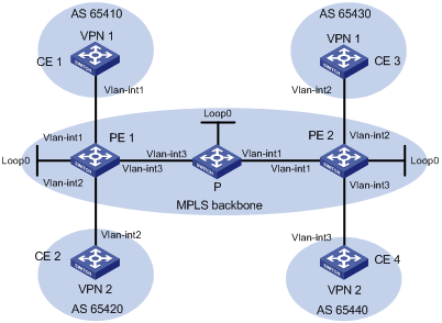
|
Interface |
IP address |
Device |
Interface |
IP address |
|
|
CE 1 |
Vlan-int1 |
10.1.1.1/24 |
P |
Loop0 |
2.2.2.9/32 |
|
PE 1 |
Loop0 |
1.1.1.9/32 |
|
Vlan-int1 |
172.2.1.1/24 |
|
|
Vlan-int1 |
10.1.1.2/24 |
|
Vlan-int3 |
172.1.1.2/24 |
|
|
Vlan-int3 |
172.1.1.1/24 |
PE 2 |
Loop0 |
3.3.3.9/32 |
|
|
Vlan-int2 |
10.2.1.2/24 |
|
Vlan-int1 |
172.2.1.2/24 |
|
CE 2 |
Vlan-int2 |
10.2.1.1/24 |
|
Vlan-int2 |
10.3.1.2/24 |
|
CE 3 |
Vlan-int2 |
10.3.1.1/24 |
|
Vlan-int3 |
10.4.1.2/24 |
|
CE 4 |
Vlan-int3 |
10.4.1.1/24 |
|
|
|
Configuration procedure
1. Configure an IGP on the MPLS backbone to ensure IP connectivity within the backbone.
# Configure PE 1.
<PE1> system-view
[PE1] interface loopback 0
[PE1-LoopBack0] ip address 1.1.1.9 32
[PE1-LoopBack0] quit
[PE1] interface vlan-interface 3
[PE1-Vlan-interface3] ip address 172.1.1.1 24
[PE1- Vlan-interface3] quit
[PE1] ospf
[PE1-ospf-1] area 0
[PE1-ospf-1-area-0.0.0.0] network 172.1.1.0 0.0.0.255
[PE1-ospf-1-area-0.0.0.0] network 1.1.1.9 0.0.0.0
[PE1-ospf-1-area-0.0.0.0] quit
[PE1-ospf-1] quit
# Configure the P switch.
<P> system-view
[P] interface loopback 0
[P-LoopBack0] ip address 2.2.2.9 32
[P-LoopBack0] quit
[P] interface vlan-interface 3
[P-Vlan-interface3] ip address 172.1.1.2 24
[P- Vlan-interface3] quit
[P] interface vlan-interface 1
[P-Vlan-interface1] ip address 172.2.1.1 24
[P-Vlan-interface1] quit
[P] ospf
[P-ospf-1] area 0
[P-ospf-1-area-0.0.0.0] network 172.1.1.0 0.0.0.255
[P-ospf-1-area-0.0.0.0] network 172.2.1.0 0.0.0.255
[P-ospf-1-area-0.0.0.0] network 2.2.2.9 0.0.0.0
[P-ospf-1-area-0.0.0.0] quit
[P-ospf-1] quit
# Configure PE 2.
<PE2> system-view
[PE2] interface loopback 0
[PE2-LoopBack0] ip address 3.3.3.9 32
[PE2-LoopBack0] quit
[PE2] interface vlan-interface 1
[PE2-Vlan-interface1] ip address 172.2.1.2 24
[PE2-Vlan-interface1] quit
[PE2] ospf
[PE2-ospf-1] area 0
[PE2-ospf-1-area-0.0.0.0] network 172.2.1.0 0.0.0.255
[PE2-ospf-1-area-0.0.0.0] network 3.3.3.9 0.0.0.0
[PE2-ospf-1-area-0.0.0.0] quit
[PE2-ospf-1] quit
After you complete the configuration, OSPF adjacencies are established between PE 1, P, and PE 2. Issue the display ospf peer command. You can see that the adjacency status is Full. Issue the display ip routing-table command. You can see that the PEs have learned the loopback route of each other. The following takes PE 1 as an example:
[PE1] display ip routing-table
Routing Tables: Public
Destinations : 8 Routes : 8
Destination/Mask Proto Pre Cost NextHop Interface
1.1.1.9/32 Direct 0 0 127.0.0.1 InLoop0
2.2.2.9/32 OSPF 10 1 172.1.1.2 Vlan3
3.3.3.9/32 OSPF 10 2 172.1.1.2 Vlan3
127.0.0.0/8 Direct 0 0 127.0.0.1 InLoop0
127.0.0.1/32 Direct 0 0 127.0.0.1 InLoop0
172.1.1.0/24 Direct 0 0 172.1.1.1 Vlan3
172.1.1.1/32 Direct 0 0 127.0.0.1 InLoop0
172.2.1.0/24 OSPF 10 1 172.1.1.2 Vlan3
[PE1] display ospf peer verbose
OSPF Process 1 with Router ID 1.1.1.9
Neighbors
Area 0.0.0.0 interface 172.1.1.1(Vlan-interface3)'s neighbors
Router ID: 172.1.1.2 Address: 172.1.1.2 GR State: Normal
State: Full Mode:Nbr is Master Priority: 1
DR: 172.1.1.1 BDR: 172.1.1.2 MTU: 0
Dead timer due in 38 sec
Neighbor is up for 00:02:44
Authentication Sequence: [ 0 ]
Neighbor state change count: 5
2. Configure basic MPLS configuration and MPLS LDP on the MPLS backbone to establish LDP LSPs.
# Configure PE 1.
[PE1] mpls lsr-id 1.1.1.9
[PE1] mpls
[PE1-mpls] quit
[PE1] mpls ldp
[PE1-mpls-ldp] quit
[PE1] interface vlan-interface 3
[PE1-Vlan-interface3] mpls
[PE1-Vlan-interface3] mpls ldp
[PE1-Vlan-interface3] quit
# Configure the P switch.
[P] mpls lsr-id 2.2.2.9
[P] mpls
[P-mpls] quit
[P] mpls ldp
[P-mpls-ldp] quit
[P] interface vlan-interface 3
[P-Vlan-interface3] mpls
[P-Vlan-interface3] mpls ldp
[P-Vlan-interface3] quit
[P] interface vlan-interface 1
[P-Vlan-interface1] mpls
[P-Vlan0interface1] mpls ldp
[P-Vlan-interface1] quit
# Configure PE 2.
[PE2] mpls lsr-id 3.3.3.9
[PE2] mpls
[PE2-mpls] quit
[PE2] mpls ldp
[PE2-mpls-ldp] quit
[PE2] interface vlan-interface 1
[PE2-Vlan-interface1] mpls
[PE2-Vlan-interface1] mpls ldp
[PE2-Vlan-interface1] quit
After you complete the previous configuration, LDP sessions are established between PE 1, P, and PE 2. Issue the display mpls ldp session command. You can see that the Status field has a value of Operational. Issue the display mpls ldp lsp command. You can see the LSPs established by LDP. The following takes PE 1 as an example:
[PE1] display mpls ldp session
LDP Session(s) in Public Network
Total number of sessions: 1
----------------------------------------------------------------
Peer-ID Status LAM SsnRole FT MD5 KA-Sent/Rcv
---------------------------------------------------------------
2.2.2.9:0 Operational DU Passive Off Off 5/5
---------------------------------------------------------------
LAM : Label Advertisement Mode FT : Fault Tolerance
[PE1] display mpls ldp lsp
LDP LSP Information
------------------------------------------------------------------
SN DestAddress/Mask In/OutLabel Next-Hop In/Out-Interface
------------------------------------------------------------------
1 1.1.1.9/32 3/NULL 127.0.0.1 -------/InLoop0
2 2.2.2.9/32 NULL/3 172.1.1.2 -------/Vlan-interface3
3 3.3.3.9/32 NULL/1024 172.1.1.2 -------/Vlan-interface3
------------------------------------------------------------------
A '*' before an LSP means the LSP is not established
A '*' before a Label means the USCB or DSCB is stale
3. Configure VPN instances on PEs to allow CEs to access.
# Configure PE 1.
[PE1] ip vpn-instance vpn1
[PE1-vpn-instance-vpn1] route-distinguisher 100:1
[PE1-vpn-instance-vpn1] vpn-target 111:1
[PE1-vpn-instance-vpn1] quit
[PE1] ip vpn-instance vpn2
[PE1-vpn-instance-vpn2] route-distinguisher 100:2
[PE1-vpn-instance-vpn2] vpn-target 222:2
[PE1-vpn-instance-vpn2] quit
[PE1] interface vlan-interface 1
[PE1-Vlan-interface1] ip binding vpn-instance vpn1
[PE1-Vlan-interface1] ip address 10.1.1.2 24
[PE1-Vlan-interface1] quit
[PE1] interface vlan-interface 2
[PE1-Vlan-interface2] ip binding vpn-instance vpn2
[PE1-Vlan-interface2] ip address 10.2.1.2 24
[PE1-Vlan-interface2] quit
# Configure PE 2.
[PE2] ip vpn-instance vpn1
[PE2-vpn-instance-vpn1] route-distinguisher 200:1
[PE2-vpn-instance-vpn1] vpn-target 111:1
[PE2-vpn-instance-vpn1] quit
[PE2] ip vpn-instance vpn2
[PE2-vpn-instance-vpn2] route-distinguisher 200:2
[PE2-vpn-instance-vpn2] vpn-target 222:2
[PE2-vpn-instance-vpn2] quit
[PE2] interface vlan-interface 2
[PE2-Vlan-interface2] ip binding vpn-instance vpn1
[PE2-Vlan-interface2] ip address 10.3.1.2 24
[PE2-Vlan-interface2] quit
[PE2] interface vlan-interface 3
[PE2-Vlan-interface3] ip binding vpn-instance vpn2
[PE2-Vlan-interface3] ip address 10.4.1.2 24
[PE2-Vlan-interface3] quit
# Configure IP addresses for the CEs as required in Figure 20. (Details not shown)
After you complete the configuration, issue the display ip vpn-instance command on the PEs to view the configuration of the VPN instance. The PEs can their respective CEs. The following takes PE 1 as an example:
[PE1] display ip vpn-instance
Total VPN-Instances configured : 2
VPN-Instance Name RD Create time
vpn1 100:1 2009/01/22 13:02:21
vpn2 100:2 2009/01/22 13:02:40
[PE1] ping -vpn-instance vpn1 10.1.1.1
PING 10.1.1.1: 56 data bytes, press CTRL_C to break
Reply from 10.1.1.1: bytes=56 Sequence=1 ttl=255 time=56 ms
Reply from 10.1.1.1: bytes=56 Sequence=2 ttl=255 time=4 ms
Reply from 10.1.1.1: bytes=56 Sequence=3 ttl=255 time=4 ms
Reply from 10.1.1.1: bytes=56 Sequence=4 ttl=255 time=52 ms
Reply from 10.1.1.1: bytes=56 Sequence=5 ttl=255 time=3 ms
--- 10.1.1.1 ping statistics ---
5 packet(s) transmitted
5 packet(s) received
0.00% packet loss
round-trip min/avg/max = 3/23/56 ms
4. Establish EBGP peer relationships between PEs and CEs to allow VPN routes to be redistributed.
# Configure CE 1.
<CE1> system-view
[CE1] bgp 65410
[CE1-bgp] peer 10.1.1.2 as-number 100
[CE1-bgp] import-route direct
[CE1-bgp] quit
|
|
NOTE: The configurations for the other three CEs are similar to those for CE 1. (Details not shown) |
# Configure PE 1.
[PE1] bgp 100
[PE1-bgp] ipv4-family vpn-instance vpn1
[PE1-bgp-vpn1] peer 10.1.1.1 as-number 65410
[PE1-bgp-vpn1] import-route direct
[PE1-bgp-vpn1] quit
[PE1-bgp] ipv4-family vpn-instance vpn2
[PE1-bgp-vpn2] peer 10.2.1.1 as-number 65420
[PE1-bgp-vpn2] import-route direct
[PE1-bgp-vpn2] quit
[PE1-bgp] quit
|
|
NOTE: The configurations for PE 2 are similar to those for PE 1. (Details not shown) |
After you complete the configuration, issue the display bgp vpnv4 vpn-instance peer command on the PEs. You will see that BGP peer relationships have been established between PEs and CEs, and have reached Established state. Take PE 1 for example:
[PE1] display bgp vpnv4 vpn-instance vpn1 peer
BGP local router ID : 1.1.1.9
Local AS number : 100
Total number of peers : 1 Peers in established state : 1
Peer AS MsgRcvd MsgSent OutQ PrefRcv Up/Down State
10.1.1.1 65410 11 9 0 1 00:06:37 Established
5. Configure MP-IBGP peers between PEs.
# Configure PE 1.
[PE1] bgp 100
[PE1-bgp] peer 3.3.3.9 as-number 100
[PE1-bgp] peer 3.3.3.9 connect-interface loopback 0
[PE1-bgp] ipv4-family vpnv4
[PE1-bgp-af-vpnv4] peer 3.3.3.9 enable
[PE1-bgp-af-vpnv4] quit
[PE1-bgp] quit
# Configure PE 2.
[PE2] bgp 100
[PE2-bgp] peer 1.1.1.9 as-number 100
[PE2-bgp] peer 1.1.1.9 connect-interface loopback 0
[PE2-bgp] ipv4-family vpnv4
[PE2-bgp-af-vpnv4] peer 1.1.1.9 enable
[PE2-bgp-af-vpnv4] quit
[PE2-bgp] quit
After you complete the configuration, issue the display bgp peer command or the display bgp vpnv4 all peer command on the PEs. You will see that a BGP peer relationship in Established state has been established between the PEs. Take PE 1 for example:
[PE1] display bgp peer
BGP local router ID : 1.1.1.9
Local AS number : 100
Total number of peers : 1 Peers in established state : 1
Peer AS MsgRcvd MsgSent OutQ PrefRcv Up/Down State
3.3.3.9 100 2 6 0 0 00:00:12 Established
6. Verify your configuration.
Issue the display ip routing-table vpn-instance command on the PEs. You will see the routes to the CEs. The following takes PE 1 as an example:
[PE1] display ip routing-table vpn-instance vpn1
Routing Tables: vpn1
Destinations : 5 Routes : 5
Destination/Mask Proto Pre Cost NextHop Interface
10.1.1.0/24 Direct 0 0 10.1.1.2 Vlan11
10.1.1.2/32 Direct 0 0 127.0.0.1 InLoop0
10.3.1.0/24 BGP 255 0 3.3.3.9 NULL0
127.0.0.0/8 Direct 0 0 127.0.0.1 InLoop0
127.0.0.1/32 Direct 0 0 127.0.0.1 InLoop0
[PE1] display ip routing-table vpn-instance vpn2
Routing Tables: vpn2
Destinations : 5 Routes : 5
Destination/Mask Proto Pre Cost NextHop Interface
10.2.1.0/24 Direct 0 0 10.2.1.2 Vlan12
10.2.1.2/32 Direct 0 0 127.0.0.1 InLoop0
10.4.1.0/24 BGP 255 0 3.3.3.9 NULL0
127.0.0.0/8 Direct 0 0 127.0.0.1 InLoop0
127.0.0.1/32 Direct 0 0 127.0.0.1 InLoop0
CEs of the same VPN can ping each other, whereas those of different VPNs are not. For example, CE 1 can ping CE 3 (10.3.1.1), but it cannot ping CE 4 (10.4.1.1):
[CE1] ping 10.3.1.1
PING 10.3.1.1: 56 data bytes, press CTRL_C to break
Reply from 10.3.1.1: bytes=56 Sequence=1 ttl=253 time=72 ms
Reply from 10.3.1.1: bytes=56 Sequence=2 ttl=253 time=34 ms
Reply from 10.3.1.1: bytes=56 Sequence=3 ttl=253 time=50 ms
Reply from 10.3.1.1: bytes=56 Sequence=4 ttl=253 time=50 ms
Reply from 10.3.1.1: bytes=56 Sequence=5 ttl=253 time=34 ms
--- 10.3.1.1 ping statistics ---
5 packet(s) transmitted
5 packet(s) received
0.00% packet loss
round-trip min/avg/max = 34/48/72 ms
[CE1] ping 10.4.1.1
PING 10.4.1.1: 56 data bytes, press CTRL_C to break
Request time out
Request time out
Request time out
Request time out
Request time out
--- 10.4.1.1 ping statistics ---
5 packet(s) transmitted
0 packet(s) received
100.00% packet loss
Configuring MPLS L3VPNs using IBGP between PE and CE
Network requirements
CE 1 and CE 3 belong to VPN 1. CE 2 and CE 4 belong to VPN 2. Users of different VPNs cannot access each other.
Specify the import and export route targets as 111:1 for VPN 1 and as 222:2 for VPN 2.
Use IBGP to exchange VPN routing information between CE and PE.
In the MPLS backbone, use OSPF to ensure IP connectivity use MP-IBGP to exchange VPN routing information.
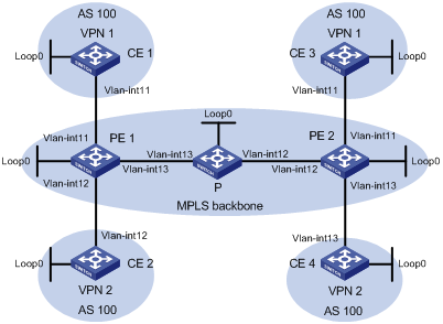
|
Device |
Interface |
IP address |
Device |
Interface |
IP address |
|
PE 1 |
Loop0 |
1.1.1.9/32 |
PE 2 |
Loop0 |
3.3.3.9/32 |
|
|
Vlan-int11 |
10.1.1.2/24 |
|
Vlan-int12 |
172.2.1.2/24 |
|
|
Vlan-int13 |
172.1.1.1/24 |
|
Vlan-int11 |
10.3.1.2/24 |
|
|
Vlan-int12 |
10.2.1.2/24 |
|
Vlan-int13 |
10.4.1.2/24 |
|
CE 1 |
Loop0 |
4.4.4.9/32 |
P |
Loop0 |
2.2.2.9/32 |
|
|
Vlan-int11 |
10.1.1.1/24 |
|
Vlan-int12 |
172.2.1.1/24 |
|
CE 2 |
Loop0 |
5.5.5.9/32 |
|
Vlan-int13 |
172.1.1.2/24 |
|
|
Vlan-int12 |
10.2.1.1/24 |
CE 4 |
Loop0 |
7.7.7.9/32 |
|
CE 3 |
Loop0 |
6.6.6.9/32 |
|
Vlan-int13 |
10.4.1.1/24 |
|
|
Vlan-int11 |
10.3.1.1/24 |
|
|
|
|
|
|
|
|
|
|
Configuration procedure
1. Configure an IGP on the MPLS backbone to ensure IP connectivity within the backbone.
# Configure PE 1.
<PE1> system-view
[PE1] interface loopback 0
[PE1-LoopBack0] ip address 1.1.1.9 32
[PE1-LoopBack0] quit
[PE1] interface vlan-interface 13
[PE1-Vlan-interface13] ip address 172.1.1.1 24
[PE1-Vlan-interface13] quit
[PE1] ospf
[PE1-ospf-1] area 0
[PE1-ospf-1-area-0.0.0.0] network 172.1.1.0 0.0.0.255
[PE1-ospf-1-area-0.0.0.0] network 1.1.1.9 0.0.0.0
[PE1-ospf-1-area-0.0.0.0] quit
[PE1-ospf-1] quit
# Configure the P switch.
<P> system-view
[P] interface loopback 0
[P-LoopBack0] ip address 2.2.2.9 32
[P-LoopBack0] quit
[P] interface vlan-interface 13
[P-Vlan-interface13] ip address 172.1.1.2 24
[P-Vlan-interface13] quit
[P] interface vlan-interface 12
[P-Vlan-interface12] ip address 172.2.1.1 24
[P-Vlan-interface12] quit
[P] ospf
[P-ospf-1] area 0
[P-ospf-1-area-0.0.0.0] network 172.1.1.0 0.0.0.255
[P-ospf-1-area-0.0.0.0] network 172.2.1.0 0.0.0.255
[P-ospf-1-area-0.0.0.0] network 2.2.2.9 0.0.0.0
[P-ospf-1-area-0.0.0.0] quit
[P-ospf-1] quit
# Configure PE 2.
<PE2> system-view
[PE2] interface loopback 0
[PE2-LoopBack0] ip address 3.3.3.9 32
[PE2-LoopBack0] quit
[PE2] interface vlan-interface 12
[PE2-Vlan-interface12] ip address 172.2.1.2 24
[PE2-Vlan-interface12] quit
[PE2] ospf
[PE2-ospf-1] area 0
[PE2-ospf-1-area-0.0.0.0] network 172.2.1.0 0.0.0.255
[PE2-ospf-1-area-0.0.0.0] network 3.3.3.9 0.0.0.0
[PE2-ospf-1-area-0.0.0.0] quit
[PE2-ospf-1] quit
After you complete the configuration, P establishes an OSPF adjacency with PE 1 and PE 2 respectively. Issue the display ospf peer command. The output shows that the adjacency status is Full. Issue the display ip routing-table command. The output shows that the PEs have learned the routes to the loopback interfaces of each other. Take PE 1 as an example:
[PE1] display ip routing-table
Routing Tables: Public
Destinations : 8 Routes : 8
Destination/Mask Proto Pre Cost NextHop Interface
1.1.1.9/32 Direct 0 0 127.0.0.1 InLoop0
2.2.2.9/32 OSPF 10 1 172.1.1.2 Vlan13
3.3.3.9/32 OSPF 10 2 172.1.1.2 Vlan13
127.0.0.0/8 Direct 0 0 127.0.0.1 InLoop0
127.0.0.1/32 Direct 0 0 127.0.0.1 InLoop0
172.1.1.0/24 Direct 0 0 172.1.1.1 Vlan13
172.1.1.1/32 Direct 0 0 127.0.0.1 InLoop0
172.2.1.0/24 OSPF 10 1 172.1.1.2 Vlan13
[PE1] display ospf peer verbose
OSPF Process 1 with Router ID 1.1.1.9
Neighbors
Area 0.0.0.0 interface 172.1.1.1(Vlan-interface13)'s neighbors
Router ID: 172.1.1.2 Address: 172.1.1.2 GR State: Normal
State: Full Mode:Nbr is Master Priority: 1
DR: 172.1.1.1 BDR: 172.1.1.2 MTU: 0
Dead timer due in 38 sec
Neighbor is up for 00:02:44
Authentication Sequence: [ 0 ]
Neighbor state change count: 5
2. Configure basic MPLS and MPLS LDP on the MPLS backbone to establish LDP LSPs.
# Configure PE 1.
[PE1] mpls lsr-id 1.1.1.9
[PE1] mpls
[PE1-mpls] quit
[PE1] mpls ldp
[PE1-mpls-ldp] quit
[PE1] interface vlan-interface 13
[PE1-Vlan-interface13] mpls
[PE1-Vlan-interface13] mpls ldp
[PE1-Vlan-interface13] quit
# Configure the P switch.
[P] mpls lsr-id 2.2.2.9
[P] mpls
[P-mpls] quit
[P] mpls ldp
[P-mpls-ldp] quit
[P] interface vlan-interface 13
[P-Vlan-interface13] mpls
[P-Vlan-interface13] mpls ldp
[P-Vlan-interface13] quit
[P] interface vlan-interface 12
[P-Vlan-interface12] mpls
[P-Vlan0interface12] mpls ldp
[P-Vlan-interface12] quit
# Configure PE 2.
[PE2] mpls lsr-id 3.3.3.9
[PE2] mpls
[PE2-mpls] quit
[PE2] mpls ldp
[PE2-mpls-ldp] quit
[PE2] interface vlan-interface 12
[PE2-Vlan-interface12] mpls
[PE2-Vlan-interface12] mpls ldp
[PE2-Vlan-interface12] quit
After you complete the configuration, P establishes an LDP session with PE 1 and PE 2, respectively. Issue the display mpls ldp session command. The output shows that the session status is Operational. Issue the display mpls ldp lsp command. The output shows the LSPs established by LDP. Take PE 1 as an example:
[PE1] display mpls ldp session
LDP Session(s) in Public Network
Total number of sessions: 1
----------------------------------------------------------------
Peer-ID Status LAM SsnRole FT MD5 KA-Sent/Rcv
---------------------------------------------------------------
2.2.2.9:0 Operational DU Passive Off Off 5/5
---------------------------------------------------------------
LAM : Label Advertisement Mode FT : Fault Tolerance
[PE1] display mpls ldp lsp
LDP LSP Information
------------------------------------------------------------------
SN DestAddress/Mask In/OutLabel Next-Hop In/Out-Interface
------------------------------------------------------------------
1 1.1.1.9/32 3/NULL 127.0.0.1 -------/InLoop0
2 2.2.2.9/32 NULL/3 172.1.1.2 -------/Vlan-interface13
3 3.3.3.9/32 NULL/1024 172.1.1.2 -------/Vlan-interface13
------------------------------------------------------------------
A '*' before an LSP means the LSP is not established
A '*' before a Label means the USCB or DSCB is stale
3. Configure VPN instances on PEs to allow CEs to access.
# Configure PE 1.
[PE1] ip vpn-instance vpn1
[PE1-vpn-instance-vpn1] route-distinguisher 100:1
[PE1-vpn-instance-vpn1] vpn-target 111:1
[PE1-vpn-instance-vpn1] quit
[PE1] ip vpn-instance vpn2
[PE1-vpn-instance-vpn2] route-distinguisher 100:2
[PE1-vpn-instance-vpn2] vpn-target 222:2
[PE1-vpn-instance-vpn2] quit
[PE1] interface vlan-interface 11
[PE1-Vlan-interface11] ip binding vpn-instance vpn1
[PE1-Vlan-interface11] ip address 10.1.1.2 24
[PE1-Vlan-interface11] quit
[PE1] interface vlan-interface 12
[PE1-Vlan-interface12] ip binding vpn-instance vpn2
[PE1-Vlan-interface12] ip address 10.2.1.2 24
[PE1-Vlan-interface12] quit
# Configure PE 2.
[PE2] ip vpn-instance vpn1
[PE2-vpn-instance-vpn1] route-distinguisher 200:1
[PE2-vpn-instance-vpn1] vpn-target 111:1
[PE2-vpn-instance-vpn1] quit
[PE2] ip vpn-instance vpn2
[PE2-vpn-instance-vpn2] route-distinguisher 200:2
[PE2-vpn-instance-vpn2] vpn-target 222:2
[PE2-vpn-instance-vpn2] quit
[PE2] interface vlan-interface 11
[PE2-Vlan-interface11] ip binding vpn-instance vpn1
[PE2-Vlan-interface11] ip address 10.3.1.2 24
[PE2-Vlan-interface11] quit
[PE2] interface vlan-interface 13
[PE2-Vlan-interface13] ip binding vpn-instance vpn2
[PE2-Vlan-interface13] ip address 10.4.1.2 24
[PE2-Vlan-interface13] quit
# Configure IP addresses for the CEs as per in Figure 21. (Details not shown)
After completing the configurations, issue the display ip vpn-instance command on the PEs to view the configuration of the VPN instances. Use the ping command to test connectivity between the PEs and their attached CEs. The PEs can ping their attached CEs. Take PE 1 and CE 1 as examples:
[PE1] display ip vpn-instance
Total VPN-Instances configured : 2
VPN-Instance Name RD Create time
vpn1 100:1 2009/01/22 13:02:21
vpn2 100:2 2009/01/22 13:02:40
[PE1] ping -vpn-instance vpn1 10.1.1.1
PING 10.1.1.1: 56 data bytes, press CTRL_C to break
Reply from 10.1.1.1: bytes=56 Sequence=1 ttl=255 time=56 ms
Reply from 10.1.1.1: bytes=56 Sequence=2 ttl=255 time=4 ms
Reply from 10.1.1.1: bytes=56 Sequence=3 ttl=255 time=4 ms
Reply from 10.1.1.1: bytes=56 Sequence=4 ttl=255 time=52 ms
Reply from 10.1.1.1: bytes=56 Sequence=5 ttl=255 time=3 ms
--- 10.1.1.1 ping statistics ---
5 packet(s) transmitted
5 packet(s) received
0.00% packet loss
round-trip min/avg/max = 3/23/56 ms
4. Establish IBGP peer relationships between PEs and CEs to redistribute VPN routes, and configure routing policies to change the next hop of the routes.
# On CE 1, configure PE 1 as the IBGP peer, and configure a routing policy for the routes received from PE 1, changing the next hop address of the routes to the IP address of PE 1.
<CE1> system-view
[CE1] route-policy ce-ibgp permit node 0
[CE1-route-policy] apply ip-address next-hop 10.1.1.2
[CE1-route-policy] quit
[CE1] bgp 100
[CE1-bgp] peer 10.1.1.2 as-number 100
[CE1-bgp] peer 10.1.1.2 route-policy ce-ibgp import
[CE1-bgp] import-route direct
[CE1-bgp] quit
|
|
NOTE: The configurations for the other three CEs (CE 2 through CE 4) are similar to those for CE 1. (Details not shown) |
# On PE 1, configure the CE 1 and CE 2 as the IBGP peers, and configure PE 1 as the route reflector.
[PE1] bgp 100
[PE1-bgp] ipv4-family vpn-instance vpn1
[PE1-bgp-vpn1] peer 10.1.1.1 as-number 100
[PE1-bgp-vpn1] peer 10.1.1.1 reflect-client
[PE1-bgp-vpn1] import-route direct
[PE1-bgp-vpn1] quit
[PE1-bgp] ipv4-family vpn-instance vpn2
[PE1-bgp-vpn2] peer 10.2.1.1 as-number 100
[PE1-bgp-vpn2] peer 10.2.1.1 reflect-client
[PE1-bgp-vpn2] import-route direct
[PE1-bgp-vpn2] quit
[PE1-bgp] quit
|
|
NOTE: The configurations for PE 2 are similar to those for PE 1. (Details not shown) |
Issue the display bgp vpnv4 vpn-instance peer command on the PEs. The output shows that BGP peer relationships have been established between the PEs and CEs, and have reached the Established state. Take the BGP peer relationship between PE 1 and CE 1 as an example:
[PE1] display bgp vpnv4 vpn-instance vpn1 peer
BGP local router ID : 1.1.1.9
Local AS number : 100
Total number of peers : 1 Peers in established state : 1
Peer AS MsgRcvd MsgSent OutQ PrefRcv Up/Down State
10.1.1.1 100 26 21 0 2 00:11:08 Established
5. Configure an MP-IBGP peer relationship between PEs.
# On PE 1, configure PE 2 as the MP-IBGP peer, and configure a routing policy for the routes received from PE 2, changing the next hop address of the routes as the loopback interface address of PE 2.
[PE1] route-policy pe-ibgp permit node 0
[PE1-route-policy] apply ip-address next-hop 3.3.3.9
[PE1-route-policy] quit
[PE1] bgp 100
[PE1-bgp] peer 3.3.3.9 as-number 100
[PE1-bgp] peer 3.3.3.9 connect-interface loopback 0
[PE1-bgp] ipv4-family vpnv4
[PE1-bgp-af-vpnv4] peer 3.3.3.9 route-policy pe-ibgp import
[PE1-bgp-af-vpnv4] peer 3.3.3.9 enable
[PE1-bgp-af-vpnv4] quit
[PE1-bgp] quit
# On PE 2, configure PE 1 as the MP-IBGP peer, and configure a routing policy for the routes received from PE 1, changing the next hop address of the routes as the loopback interface address of PE 1.
[PE2] route-policy pe-ibgp permit node 0
[PE2-route-policy] apply ip-address next-hop 1.1.1.9
[PE2-route-policy] quit
[PE2] bgp 100
[PE2-bgp] peer 1.1.1.9 as-number 100
[PE2-bgp] peer 1.1.1.9 connect-interface loopback 0
[PE2-bgp] ipv4-family vpnv4
[PE2-bgp-af-vpnv4] peer 1.1.1.9 route-policy pe-ibgp import
[PE2-bgp-af-vpnv4] peer 1.1.1.9 enable
[PE2-bgp-af-vpnv4] quit
[PE2-bgp] quit
Issue the display bgp peer command or the display bgp vpnv4 all peer command on the PEs. The output shows that a BGP peer relationship has been established between the PEs, and has reached the Established state. Take PE 1 as an example:
[PE1] display bgp peer
BGP local router ID : 1.1.1.9
Local AS number : 100
Total number of peers : 1 Peers in established state : 1
Peer AS MsgRcvd MsgSent OutQ PrefRcv Up/Down State
3.3.3.9 100 4 8 0 0 00:00:09 Established
6. Verify your configuration.
Issue the display ip routing-table vpn-instance command on the PEs. The output shows the routes to the peer CEs. Take PE 1 as an example:
[PE1] display ip routing-table vpn-instance vpn1
Routing Tables: vpn1
Destinations : 7 Routes : 7
Destination/Mask Proto Pre Cost NextHop Interface
4.4.4.9/32 BGP 255 0 10.1.1.1 Vlan11
6.6.6.9/32 BGP 255 0 3.3.3.9 NULL0
10.1.1.0/24 Direct 0 0 10.1.1.2 Vlan11
10.1.1.2/32 Direct 0 0 127.0.0.1 InLoop0
10.3.1.0/24 BGP 255 0 3.3.3.9 NULL0
127.0.0.0/8 Direct 0 0 127.0.0.1 InLoop0
127.0.0.1/32 Direct 0 0 127.0.0.1 InLoop0
[PE1] display ip routing-table vpn-instance vpn2
Routing Tables: vpn2
Destinations : 5 Routes : 5
Destination/Mask Proto Pre Cost NextHop Interface
5.5.5.9/32 BGP 255 0 10.2.1.1 Vlan12
7.7.7.9/32 BGP 255 0 3.3.3.9 NULL0
10.2.1.0/24 Direct 0 0 10.2.1.2 Vlan12
10.2.1.2/32 Direct 0 0 127.0.0.1 InLoop0
10.4.1.0/24 BGP 255 0 3.3.3.9 NULL0
127.0.0.0/8 Direct 0 0 127.0.0.1 InLoop0
127.0.0.1/32 Direct 0 0 127.0.0.1 InLoop0
CEs of the same VPN can ping each other, whereas those of different VPNs can not. For example, CE 1 can ping CE 3 (6.6.6.9), but cannot ping CE 4 (7.7.7.9):
[CE1] ping 6.6.6.9
PING 6.6.6.9: 56 data bytes, press CTRL_C to break
Reply from 6.6.6.9: bytes=56 Sequence=1 ttl=253 time=72 ms
Reply from 6.6.6.9: bytes=56 Sequence=2 ttl=253 time=34 ms
Reply from 6.6.6.9: bytes=56 Sequence=3 ttl=253 time=50 ms
Reply from 6.6.6.9: bytes=56 Sequence=4 ttl=253 time=50 ms
Reply from 6.6.6.9: bytes=56 Sequence=5 ttl=253 time=34 ms
--- 6.6.6.9 ping statistics ---
5 packet(s) transmitted
5 packet(s) received
0.00% packet loss
round-trip min/avg/max = 34/48/72 ms
[CE1] ping 7.7.7.9
PING 7.7.7.9: 56 data bytes, press CTRL_C to break
Request time out
Request time out
Request time out
Request time out
Request time out
--- 7.7.7.9 ping statistics ---
5 packet(s) transmitted
0 packet(s) received
100.00% packet loss
Configuring a hub-spoke network
Network requirements
The spoke-CEs are not permitted to communicate with each other directly. Data transmission between them depends on the hub-CE.
Configure EBGP to exchange VPN routing information between spoke-CE and spoke-PE, and between hub-CE and hub-PE.
Configure OSPF between spoke-PE and hub-PE to ensure IP connectivity between PEs, and configure MP-IBGP to exchange VPN routing information.
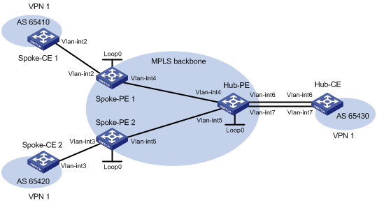
|
Device |
Interface |
IP address |
Device |
Interface |
IP address |
|
Spoke-CE 1 |
Vlan-int2 |
10.1.1.1/24 |
Hub-CE |
Vlan-int6 |
10.3.1.1/24 |
|
Spoke-PE 1 |
Loop0 |
1.1.1.9/32 |
|
Vlan-int7 |
10.4.1.1/24 |
|
|
Vlan-int2 |
10.1.1.2/24 |
Hub-PE |
Loop0 |
2.2.2.9/32 |
|
|
Vlan-int4 |
172.1.1.1/24 |
|
Vlan-int4 |
172.1.1.2/24 |
|
Spoke-CE 2 |
Vlan-int3 |
10.2.1.1/24 |
|
Vlan-int5 |
172.2.1.2/24 |
|
Spoke-PE 2 |
Loop0 |
3.3.3.9/32 |
|
Vlan-int6 |
10.3.1.2/24 |
|
|
Vlan-int3 |
10.2.1.2/24 |
|
Vlan-int7 |
10.4.1.2/24 |
|
|
Vlan-int5 |
172.2.1.1/24 |
|
|
|
Configuration procedure
1. Configure an IGP in the MPLS backbone to ensure IP connectivity between spoke-PE and hub-PE.
# Configure Spoke-PE 1.
<Spoke-PE1> system-view
[Spoke-PE1] interface loopback 0
[Spoke-PE1-LoopBack0] ip address 1.1.1.9 32
[Spoke-PE1-LoopBack0] quit
[Spoke-PE1] interface vlan-interface 4
[Spoke-PE1-Vlan-interface4] ip address 172.1.1.1 24
[Spoke-PE1-Vlan-interface4] quit
[Spoke-PE1] ospf
[Spoke-PE1-ospf-1] area 0
[Spoke-PE1-ospf-1-area-0.0.0.0] network 172.1.1.0 0.0.0.255
[Spoke-PE1-ospf-1-area-0.0.0.0] network 1.1.1.9 0.0.0.0
[Spoke-PE1-ospf-1-area-0.0.0.0] quit
[Spoke-PE1-ospf-1] quit
# Configure Spoke-PE 2.
<Spoke-PE2> system-view
[Spoke-PE2] interface loopback 0
[Spoke-PE2-LoopBack0] ip address 3.3.3.9 32
[Spoke-PE2-LoopBack0] quit
[Spoke-PE2] interface vlan-interface 5
[Spoke-PE2-Vlan-interface5] ip address 172.2.1.1 24
[Spoke-PE2-Vlan-interface5] quit
[Spoke-PE2] ospf
[Spoke-PE2-ospf-1] area 0
[Spoke-PE2-ospf-1-area-0.0.0.0] network 172.2.1.0 0.0.0.255
[Spoke-PE2-ospf-1-area-0.0.0.0] network 3.3.3.9 0.0.0.0
[Spoke-PE2-ospf-1-area-0.0.0.0] quit
[Spoke-PE2-ospf-1] quit
# Configure the Hub-PE.
<Hub-PE> system-view
[Hub-PE] interface loopback 0
[Hub-PE-LoopBack0] ip address 2.2.2.9 32
[Hub-PE-LoopBack0] quit
[Hub-PE] interface vlan-interface 4
[Hub-PE-Vlan-interface4] ip address 172.1.1.2 24
[Hub-PE-Vlan-interface4] quit
[Hub-PE] interface vlan-interface 5
[Hub-PE-Vlan-interface5] ip address 172.2.1.2 24
[Hub-PE-Vlan-interface5] quit
[Hub-PE] ospf
[Hub-PE-ospf-1] area 0
[Hub-PE-ospf-1-area-0.0.0.0] network 172.1.1.0 0.0.0.255
[Hub-PE-ospf-1-area-0.0.0.0] network 172.2.1.0 0.0.0.255
[Hub-PE-ospf-1-area-0.0.0.0] network 2.2.2.9 0.0.0.0
[Hub-PE-ospf-1-area-0.0.0.0] quit
[Hub-PE-ospf-1] quit
After the configuration, OSPF adjacencies are established between Spoke-PE 1 and Hub-PE, and between Spoke-PE 2 and Hub-PE. Issue the display ospf peer command. The output shows that the adjacency status is Full. Issue the display ip routing-table command. The output shows that the PEs have learned the routes to the loopback interfaces of each other.
Take Spoke-PE 1 as an example:
[Spoke-PE1] display ip routing-table
Routing Tables: Public
Destinations : 10 Routes : 10
Destination/Mask Proto Pre Cost NextHop Interface
1.1.1.9/32 Direct 0 0 127.0.0.1 InLoop0
2.2.2.9/32 OSPF 10 1 172.1.1.2 Vlan4
3.3.3.9/32 OSPF 10 2 172.1.1.2 Vlan4
10.1.1.0/24 Direct 0 0 10.1.1.2 Vlan2
10.1.1.2/32 Direct 0 0 127.0.0.1 InLoop0
127.0.0.0/8 Direct 0 0 127.0.0.1 InLoop0
127.0.0.1/32 Direct 0 0 127.0.0.1 InLoop0
172.1.1.0/24 Direct 0 0 172.1.1.1 Vlan4
172.1.1.1/32 Direct 0 0 127.0.0.1 InLoop0
172.2.1.0/24 OSPF 10 1 172.1.1.2 Vlan4
[Spoke-PE1] display ospf peer verbose
OSPF Process 1 with Router ID 1.1.1.9
Neighbors
Area 0.0.0.0 interface 172.1.1.1(Vlan-interface4)'s neighbors
Router ID: 2.2.2.9 Address: 172.1.1.2 GR State: Normal
State: Full Mode:Nbr is Master Priority: 1
DR: 172.1.1.1 BDR: 172.1.1.2 MTU: 0
Dead timer due in 38 sec
Neighbor is up for 00:02:44
Authentication Sequence: [ 0 ]
Neighbor state change count: 5
2. Configure basic MPLS and MPLS LDP in the MPLS backbone to establish LDP LSPs.
# Configure Spoke-PE 1.
[Spoke-PE1] mpls lsr-id 1.1.1.9
[Spoke-PE1] mpls
[Spoke-PE1-mpls] quit
[Spoke-PE1] mpls ldp
[Spoke-PE1-mpls-ldp] quit
[Spoke-PE1] interface vlan-interface 4
[Spoke-PE1-Vlan-interface4] mpls
[Spoke-PE1-Vlan-interface4] mpls ldp
[Spoke-PE1-Vlan-interface4] quit
# Configure Spoke-PE 2.
[Spoke-PE2] mpls lsr-id 3.3.3.9
[Spoke-PE2] mpls
[Spoke-PE2-mpls] quit
[Spoke-PE2] mpls ldp
[Spoke-PE2-mpls-ldp] quit
[Spoke-PE2] interface vlan-interface 5
[Spoke-PE2-Vlan-interface5] mpls
[Spoke-PE2-Vlan-interface5] mpls ldp
[Spoke-PE2-Vlan-interface5] quit
# Configure the Hub-PE.
[Hub-PE] mpls lsr-id 2.2.2.9
[Hub-PE] mpls
[Hub-PE-mpls] quit
[Hub-PE] mpls ldp
[Hub-PE-mpls-ldp] quit
[Hub-PE] interface vlan-interface 4
[Hub-PE-Vlan-interface4] mpls
[Hub-PE-Vlan-interface4] mpls ldp
[Hub-PE-Vlan-interface4] quit
[Hub-PE] interface vlan-interface 5
[Hub-PE-Vlan-interface5] mpls
[Hub-PE-Vlan-interface5] mpls ldp
[Hub-PE-Vlan-interface5] quit
After the configuration, LDP sessions are established between Spoke-PE 1 and Hub-PE, and between Spoke-PE 2 and Hub-PE. Issue the display mpls ldp session command. The output shows that the session status is Operational. Issue the display mpls ldp lsp command.
Takes Spoke-PE 1 as an example:
[Spoke-PE1] display mpls ldp session
LDP Session(s) in Public Network
Total number of sessions: 1
----------------------------------------------------------------
Peer-ID Status LAM SsnRole FT MD5 KA-Sent/Rcv
---------------------------------------------------------------
2.2.2.9:0 Operational DU Passive Off Off 5/5
---------------------------------------------------------------
LAM : Label Advertisement Mode FT : Fault Tolerance
[Spoke-PE1] display mpls ldp lsp
LDP LSP Information
------------------------------------------------------------------
SN DestAddress/Mask In/OutLabel Next-Hop In/Out-Interface
------------------------------------------------------------------
1 1.1.1.9/32 3/NULL 127.0.0.1 -------/InLoop0
2 2.2.2.9/32 NULL/3 172.1.1.2 -------/Vlan-interface4
3 3.3.3.9/32 NULL/1024 172.1.1.2 -------/Vlan-interface4
------------------------------------------------------------------
A '*' before an LSP means the LSP is not established
A '*' before a Label means the USCB or DSCB is stale
3. Configure VPN instances on the spoke-PEs and the hub-PE to allow CEs to access the PEs.
# Configure Spoke-PE 1.
[Spoke-PE1] ip vpn-instance vpn1
[Spoke-PE1-vpn-instance-vpn1] route-distinguisher 100:1
[Spoke-PE1-vpn-instance-vpn1] vpn-target 111:1 import-extcommunity
[Spoke-PE1-vpn-instance-vpn1] vpn-target 222:2 export-extcommunity
[Spoke-PE1-vpn-instance-vpn1] quit
[Spoke-PE1] interface vlan-interface 2
[Spoke-PE1-Vlan-interface2] ip binding vpn-instance vpn1
[Spoke-PE1-Vlan-interface2] ip address 10.1.1.2 24
[Spoke-PE1-Vlan-interface2] quit
# Configure the Spoke-PE 2.
[Spoke-PE2] ip vpn-instance vpn1
[Spoke-PE2-vpn-instance-vpn1] route-distinguisher 100:2
[Spoke-PE2-vpn-instance-vpn1] vpn-target 111:1 import-extcommunity
[Spoke-PE2-vpn-instance-vpn1] vpn-target 222:2 export-extcommunity
[Spoke-PE2-vpn-instance-vpn1] quit
[Spoke-PE2] interface vlan-interface 3
[Spoke-PE2-Vlan-interface3] ip binding vpn-instance vpn1
[Spoke-PE2-Vlan-interface3] ip address 10.2.1.2 24
[Spoke-PE2-Vlan-interface3] quit
# Configure the Hub-PE.
[Hub-PE] ip vpn-instance vpn1-in
[Hub-PE-vpn-instance-vpn1-in] route-distinguisher 100:3
[Hub-PE-vpn-instance-vpn1-in] vpn-target 222:2 import-extcommunity
[Hub-PE-vpn-instance-vpn1-in] quit
[Hub-PE] ip vpn-instance vpn1-out
[Hub-PE-vpn-instance-vpn1-out] route-distinguisher 100:4
[Hub-PE-vpn-instance-vpn1-out] vpn-target 111:1 export-extcommunity
[Hub-PE-vpn-instance-vpn1-out] quit
[Hub-PE] interface vlan-interface 6
[Hub-PE-Vlan-interface6] ip binding vpn-instance vpn1-in
[Hub-PE-Vlan-interface6] ip address 10.3.1.2 24
[Hub-PE-Vlan-interface6] quit
[Hub-PE] interface vlan-interface 7
[Hub-PE-Vlan-interface7] ip binding vpn-instance vpn1-out
[Hub-PE-Vlan-interface7] ip address 10.4.1.2 24
[Hub-PE-Vlan-interface7] quit
# Configure IP addresses for the CEs as per Figure 22. (Details not shown)
After you complete the configurations, issue the display ip vpn-instance command on the PEs to view the VPN instance configurations. Use the ping command to test connectivity between the PEs and their attached CEs. The PEs can ping their attached CEs.
Take Spoke-PE 1 as an example:
[Spoke-PE1] display ip vpn-instance
Total VPN-Instances configured : 1
VPN-Instance Name RD Create time
vpn1 100:1 2009/04/08 10:55:07
Spoke-PE 1 can ping Spoke-CE successfully:
[Spoke-PE1] ping -vpn-instance vpn1 10.1.1.1
PING 10.1.1.1: 56 data bytes, press CTRL_C to break
Reply from 10.1.1.1: bytes=56 Sequence=1 ttl=255 time=56 ms
Reply from 10.1.1.1: bytes=56 Sequence=2 ttl=255 time=4 ms
Reply from 10.1.1.1: bytes=56 Sequence=3 ttl=255 time=4 ms
Reply from 10.1.1.1: bytes=56 Sequence=4 ttl=255 time=52 ms
Reply from 10.1.1.1: bytes=56 Sequence=5 ttl=255 time=3 ms
--- 10.1.1.1 ping statistics ---
5 packet(s) transmitted
5 packet(s) received
0.00% packet loss
round-trip min/avg/max = 3/23/56 ms
4. Establish EBGP peer relationships between PEs and CEs.
# Configure Spoke-CE 1.
<Spoke-CE1> system-view
[Spoke-CE1] bgp 65410
[Spoke-CE1-bgp] peer 10.1.1.2 as-number 100
[Spoke-CE1-bgp] import-route direct
[Spoke-CE1-bgp] quit
# Configure Spoke-CE 2.
<Spoke-CE2> system-view
[Spoke-CE2] bgp 65420
[Spoke-CE2-bgp] peer 10.2.1.2 as-number 100
[Spoke-CE2-bgp] import-route direct
[Spoke-CE2-bgp] quit
# Configure the Hub-CE.
<Hub-CE> system-view
[Hub-CE] bgp 65430
[Hub-CE-bgp] peer 10.3.1.2 as-number 100
[Hub-CE-bgp] peer 10.4.1.2 as-number 100
[Hub-CE-bgp] import-route direct
[Hub-CE-bgp] quit
# Configure Spoke-PE 1.
[Spoke-PE1] bgp 100
[Spoke-PE1-bgp] ipv4-family vpn-instance vpn1
[Spoke-PE1-bgp-vpn1] peer 10.1.1.1 as-number 65410
[Spoke-PE1-bgp-vpn1] import-route direct
[Spoke-PE1-bgp-vpn1] quit
[Spoke-PE1-bgp] quit
# Configure Spoke-PE 2.
[Spoke-PE2] bgp 100
[Spoke-PE2-bgp] ipv4-family vpn-instance vpn1
[Spoke-PE2-bgp-vpn1] peer 10.2.1.1 as-number 65420
[Spoke-PE2-bgp-vpn1] import-route direct
[Spoke-PE2-bgp-vpn1] quit
[Spoke-PE2-bgp] quit
# Configure the Hub-PE.
[Hub-PE] bgp 100
[Hub-PE-bgp] ipv4-family vpn-instance vpn1-in
[Hub-PE-bgp-vpn1-in] peer 10.3.1.1 as-number 65430
[Hub-PE-bgp-vpn1-in] import-route direct
[Hub-PE-bgp-vpn1-in] quit
[Hub-PE-bgp] ipv4-family vpn-instance vpn1-out
[Hub-PE-bgp-vpn1-out] peer 10.4.1.1 as-number 65430
[Hub-PE-bgp-vpn1-out] peer 10.4.1.1 allow-as-loop
[Hub-PE-bgp-vpn1-out] import-route direct
[Hub-PE-bgp-vpn1-out] quit
[Hub-PE-bgp] quit
After you complete the configurations, issue the display bgp vpnv4 vpn-instance peer command on the PEs. The output shows that a BGP peer relationship has been established between PE and CE, and has reached the Established state.
Take the peer relationship between Spoke-PE 1 and Spoke-CE 1 as an example:
[Spoke-PE1] display bgp vpnv4 vpn-instance vpn1 peer
BGP local router ID : 1.1.1.9
Local AS number : 100
Total number of peers : 1 Peers in established state : 1
Peer AS MsgRcvd MsgSent OutQ PrefRcv Up/Down State
10.1.1.1 65410 6 7 0 2 00:03:16 Established
5. Configure an MP-IBGP peer relationship between a spoke-PE and the hub-PE.
# Configure Spoke-PE 1.
[Spoke-PE1] bgp 100
[Spoke-PE1-bgp] peer 2.2.2.9 as-number 100
[Spoke-PE1-bgp] peer 2.2.2.9 connect-interface loopback 0
[Spoke-PE1-bgp] ipv4-family vpnv4
[Spoke-PE1-bgp-af-vpnv4] peer 2.2.2.9 enable
[Spoke-PE1-bgp-af-vpnv4] quit
[Spoke-PE1-bgp] quit
# Configure Spoke-PE 2.
[Spoke-PE2] bgp 100
[Spoke-PE2-bgp] peer 2.2.2.9 as-number 100
[Spoke-PE2-bgp] peer 2.2.2.9 connect-interface loopback 0
[Spoke-PE2-bgp] ipv4-family vpnv4
[Spoke-PE2-bgp-af-vpnv4] peer 2.2.2.9 enable
[Spoke-PE2-bgp-af-vpnv4] quit
[Spoke-PE2-bgp] quit
# Configure the Hub-PE.
[Hub-PE] bgp 100
[Hub-PE-bgp] peer 1.1.1.9 as-number 100
[Hub-PE-bgp] peer 1.1.1.9 connect-interface loopback 0
[Hub-PE-bgp] peer 3.3.3.9 as-number 100
[Hub-PE-bgp] peer 3.3.3.9 connect-interface loopback 0
[Hub-PE-bgp] ipv4-family vpnv4
[Hub-PE-bgp-af-vpnv4] peer 1.1.1.9 enable
[Hub-PE-bgp-af-vpnv4] peer 3.3.3.9 enable
[Hub-PE-bgp-af-vpnv4] quit
[Hub-PE-bgp] quit
After you complete the configurations, issue the display bgp peer command or the display bgp vpnv4 all peer command on the PEs. The output shows that a BGP peer relationship has been established between the PEs, and has reached the Established state.
[Spoke-PE1] display bgp peer
BGP local router ID : 1.1.1.9
Local AS number : 100
Total number of peers : 1 Peers in established state : 1
Peer AS MsgRcvd MsgSent OutQ PrefRcv Up/Down State
2.2.2.9 100 6 5 0 0 00:00:32 Established
6. Verify your configuration.
# Issue the display ip routing-table vpn-instance command on a PE. The output shows that the PE has learned routes to each CE, and for a spoke-PE, the next hop of the route to the peer spoke-CE is the Hub-PE.
[Spoke-PE1] display ip routing-table vpn-instance vpn1
Routing Tables: vpn1
Destinations : 8 Routes : 8
Destination/Mask Proto Pre Cost NextHop Interface
10.0.0.0/24 BGP 255 0 2.2.2.9 NULL0
10.1.1.0/24 Direct 0 0 10.1.1.2 Vlan2
10.1.1.2/32 Direct 0 0 127.0.0.1 InLoop0
10.2.1.0/24 BGP 255 0 2.2.2.9 NULL0
10.3.1.0/24 BGP 255 0 2.2.2.9 NULL0
10.4.1.0/24 BGP 255 0 2.2.2.9 NULL0
127.0.0.0/8 Direct 0 0 127.0.0.1 InLoop0
127.0.0.1/32 Direct 0 0 127.0.0.1 InLoop0
# Spoke-CE 1 and Spoke-CE 2 can ping each other. The TTL value indicates that traffic from Spoke-CE 1 to Spoke-CE 2 passes six hops (255-250+1) and is forwarded through the Hub-CE.
Take Spoke-CE 1 as an example:
[Spoke-CE1] ping 10.2.1.1
PING 10.2.1.1: 56 data bytes, press CTRL_C to break
Reply from 10.2.1.1: bytes=56 Sequence=1 ttl=250 time=3 ms
Reply from 10.2.1.1: bytes=56 Sequence=2 ttl=250 time=3 ms
Reply from 10.2.1.1: bytes=56 Sequence=3 ttl=250 time=2 ms
Reply from 10.2.1.1: bytes=56 Sequence=4 ttl=250 time=2 ms
Reply from 10.2.1.1: bytes=56 Sequence=5 ttl=250 time=2 ms
--- 10.2.1.1 ping statistics ---
5 packet(s) transmitted
5 packet(s) received
0.00% packet loss
round-trip min/avg/max = 2/2/3 ms
Configuring inter-AS option A
Network requirements
CE 1 is connected to PE 1 and CE 2 is connected to PE 2. PE 1 and PE 2 are in different ASs.
Configure OSPF in each MPLS backbone.
Configure an inter-AS IPv6 MPLS L3VPN using option A, so CE 1 and CE 2 can communicate with each other within the VPN.
Figure 23 Network diagram
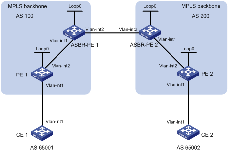
|
Device |
Interface |
IP address |
Device |
Interface |
IP address |
|
CE 1 |
Vlan-int1 |
10.1.1.1/24 |
CE 2 |
Vlan-int1 |
10.2.1.1/24 |
|
PE 1 |
Loop0 |
1.1.1.9/32 |
PE 2 |
Loop0 |
4.4.4.9/32 |
|
|
Vlan-int1 |
10.1.1.2/24 |
|
Vlan-int1 |
10.2.1.2/24 |
|
|
Vlan-int2 |
172.1.1.2/24 |
|
Vlan-int2 |
162.1.1.2/24 |
|
ASBR-PE 1 |
Loop0 |
2.2.2.9/32 |
ASBR-PE 2 |
Loop0 |
3.3.3.9/32 |
|
|
Vlan-int1 |
172.1.1.1/24 |
|
Vlan-int1 |
162.1.1.1/24 |
|
|
Vlan-int2 |
192.1.1.1/24 |
|
Vlan-int2 |
192.1.1.2/24 |
Configuration procedure
1. Configure an IGP on the MPLS backbone to ensure IP connectivity in the backbone.
This example uses OSPF. (Details not shown)
|
|
NOTE: The 32-bit loopback interface address used as the LSR ID needs to be advertised by OSPF. |
After you complete the previous configurations, each ASBR PE and the PE in the same AS are able to establish OSPF adjacencies. Issuing the display ospf peer command, you can see that the adjacencies reach the state of Full, and that PEs can learn the loopback addresses of each other.
Each ASBR PE and the PE in the same AS should be able to ping each other.
2. Configure basic MPLS and MPLS LDP on the MPLS backbone to establish LDP LSPs.
# Configure basic MPLS on PE 1 and enable MPLS LDP on the interface connected to ASBR PE 1.
<PE1> system-view
[PE1] mpls lsr-id 1.1.1.9
[PE1] mpls
[PE1-mpls] quit
[PE1] mpls ldp
[PE1-mpls-ldp] quit
[PE1] interface vlan-interface 1
[PE1-Vlan-interface1] mpls
[PE1-Vlan-interface1] mpls ldp
[PE1-Vlan-interface1] quit
# Configure basic MPLS on ASBR PE 1 and enable MPLS LDP on the interface connected to PE 1.
<ASBR-PE1> system-view
[ASBR-PE1] mpls lsr-id 2.2.2.9
[ASBR-PE1] mpls
[ASBR-PE1-mpls] quit
[ASBR-PE1] mpls ldp
[ASBR-PE1-mpls-ldp] quit
[ASBR-PE1] interface vlan-interface 1
[ASBR-PE1-Vlan-interface1] mpls
[ASBR-PE1-Vlan-interface1] mpls ldp
[ASBR-PE1-Vlan-interface1] quit
# Configure basic MPLS on ASBR PE 2 and enable MPLS LDP on the interface connected to PE 2.
<ASBR-PE2> system-view
[ASBR-PE2] mpls lsr-id 3.3.3.9
[ASBR-PE2] mpls
[ASBR-PE2-mpls] quit
[ASBR-PE2] mpls ldp
[ASBR-PE2-mpls-ldp] quit
[ASBR-PE2] interface vlan-interface 1
[ASBR-PE2-Vlan-interface1] mpls
[ASBR-PE2-Vlan-interface1] mpls ldp
[ASBR-PE2-Vlan-interface1] quit
# Configure basic MPLS on PE 2 and enable MPLS LDP on the interface connected to ASBR PE 2.
<PE2> system-view
[PE2] mpls lsr-id 4.4.4.9
[PE2] mpls
[PE2-mpls] quit
[PE2] mpls ldp
[PE2-mpls-ldp] quit
[PE2] interface vlan-interface 2
[PE2-Vlan-interface2] mpls
[PE2-Vlan-interface2] mpls ldp
[PE2-Vlan-interface2] quit
After you complete the previous configurations, each PE and the ASBR PE in the same AS are able to establish a neighbor relationship. Issuing the display mpls ldp session command on the switches, you can see that the Status field has a value of Operational in the output information.
3. Configure VPN instances on PEs to allow CEs to access.
|
|
NOTE: The VPN targets for the VPN instances of the PEs must match those for the VPN instances of the ASBR-PEs in the same AS. It is not required for PEs in different ASs. |
# Configure CE 1.
<CE1> system-view
[CE1] interface vlan-interface 1
[CE1-Vlan-interface1] ip address 10.1.1.1 24
[CE1-Vlan-interface1] quit
# Configure PE 1.
[PE1] ip vpn-instance vpn1
[PE1-vpn-instance-vpn1] route-distinguisher 100:1
[PE1-vpn-instance-vpn1] vpn-target 100:1 both
[PE1-vpn-instance-vpn1] quit
[PE1] interface vlan-interface 1
[PE1-Vlan-interface1] ip binding vpn-instance vpn1
[PE1-Vlan-interface1] ip address 10.1.1.2 24
[PE1-Vlan-interface1] quit
# Configure CE 2.
<CE2> system-view
[CE2] interface vlan-interface 1
[CE2-Vlan-interface1] ip address 10.2.1.1 24
[CE2-Vlan-interface1] quit
# Configure PE 2.
[PE2] ip vpn-instance vpn1
[PE2-vpn-instance] route-distinguisher 200:2
[PE2-vpn-instance] vpn-target 100:1 both
[PE2-vpn-instance] quit
[PE2] interface vlan-interface 1
[PE2-Vlan-interface1] ip binding vpn-instance vpn1
[PE2-Vlan-interface1] ip address 10.2.1.2 24
[PE2-Vlan-interface1] quit
# Configure ASBR PE 1, creating a VPN instance and binding the instance to the interface connected with ASBR PE 2. (ASBR PE 1 considers ASBR PE 2 its CE.)
[ASBR-PE1] ip vpn-instance vpn1
[ASBR-PE1-vpn-instance-vpn1] route-distinguisher 100:1
[ASBR-PE1-vpn-instance-vpn1] vpn-target 100:1 both
[ASBR-PE1-vpn-instance-vpn1] quit
[ASBR-PE1] interface vlan-interface 2
[ASBR-PE1-Vlan-interface2] ip binding vpn-instance vpn1
[ASBR-PE1-Vlan-interface2] ip address 192.1.1.1 24
[ASBR-PE1-Vlan-interface2] quit
# Configure ASBR PE 2, creating a VPN instance and binding the instance to the interface connected with ASBR PE 1. (ASBR PE 2 considers ASBR PE 1 its CE.)
[ASBR-PE2] ip vpn-instance vpn1
[ASBR-PE2-vpn-vpn-vpn1] route-distinguisher 200:1
[ASBR-PE2-vpn-vpn-vpn1] vpn-target 100:1 both
[ASBR-PE2-vpn-vpn-vpn1] quit
[ASBR-PE2] interface vlan-interface 2
[ASBR-PE2-Vlan-interface2] ip binding vpn-instance vpn1
[ASBR-PE2-Vlan-interface2] ip address 192.1.1.2 24
[ASBR-PE2-Vlan-interface2] quit
After completing the previous configurations, you can see the VPN instance configurations by issuing the display ip vpn-instance command.
The PEs should be able to ping the CEs and the ASBR PEs should be able to ping each other.
4. Establish EBGP peer relationships between PEs and CEs to allow VPN routes to be redistributed.
# Configure CE 1.
[CE1] bgp 65001
[CE1-bgp] peer 10.1.1.2 as-number 100
[CE1-bgp] import-route direct
[CE1-bgp] quit
# Configure PE 1.
[PE1] bgp 100
[PE1-bgp] ipv4-family vpn-instance vpn1
[PE1-bgp-vpn1] peer 10.1.1.1 as-number 65001
[PE1-bgp-vpn1] import-route direct
[PE1-bgp-vpn1] quit
[PE1-bgp] quit
# Configure CE 2.
[CE2] bgp 65002
[CE2-bgp] peer 10.2.1.2 as-number 200
[CE2-bgp] import-route direct
[CE2-bgp] quit
# Configure PE 2.
[PE2] bgp 200
[PE2-bgp] ipv4-family vpn-instance vpn1
[PE2-bgp-vpn1] peer 10.2.1.1 as-number 65002
[PE2-bgp-vpn1] import-route direct
[PE2-bgp-vpn1] quit
[PE2-bgp] quit
5. Establish IBGP peer relationships between each PE and the ASBR PE in the same AS and an EBGP peer relationship between the ASBR PEs.
# Configure PE 1.
[PE1] bgp 100
[PE1-bgp] peer 2.2.2.9 as-number 100
[PE1-bgp] peer 2.2.2.9 connect-interface loopback 0
[PE1-bgp] ipv4-family vpnv4
[PE1-bgp-af-vpnv4] peer 2.2.2.9 enable
[PE1-bgp-af-vpnv4] peer 2.2.2.9 next-hop-local
[PE1-bgp-af-vpnv4] quit
[PE1-bgp] quit
# Configure ASBR PE 1.
[ASBR-PE1] bgp 100
[ASBR-PE1-bgp] ipv4-family vpn-instance vpn1
[ASBR-PE1-bgp-vpn1] peer 192.1.1.2 as-number 200
[ASBR-PE1-bgp-vpn1] quit
[ASBR-PE1-bgp] peer 1.1.1.9 as-number 100
[ASBR-PE1-bgp] peer 1.1.1.9 connect-interface loopback 0
[ASBR-PE1-bgp] ipv4-family vpnv4
[ASBR-PE1-bgp-af-vpnv4] peer 1.1.1.9 enable
[ASBR-PE1-bgp-af-vpnv4] peer 1.1.1.9 next-hop-local
[ASBR-PE1-bgp-af-vpnv4] quit
[ASBR-PE1-bgp] quit
# Configure ASBR PE 2.
[ASBR-PE2] bgp 200
[ASBR-PE2-bgp] ipv4-family vpn-instance vpn1
[ASBR-PE2-bgp-vpn1] peer 192.1.1.1 as-number 100
[ASBR-PE2-bgp-vpn1] quit
[ASBR-PE2-bgp] peer 4.4.4.9 as-number 200
[ASBR-PE2-bgp] peer 4.4.4.9 connect-interface loopback 0
[ASBR-PE2-bgp] ipv4-family vpnv4
[ASBR-PE2-bgp-af-vpnv4] peer 4.4.4.9 enable
[ASBR-PE2-bgp-af-vpnv4] peer 4.4.4.9 next-hop-local
[ASBR-PE2-bgp-af-vpnv4] quit
[ASBR-PE2-bgp] quit
# Configure PE 2.
[PE2] bgp 200
[PE2-bgp] peer 3.3.3.9 as-number 200
[PE2-bgp] peer 3.3.3.9 connect-interface loopback 0
[PE2-bgp] ipv4-family vpnv4
[PE2-bgp-af-vpnv4] peer 3.3.3.9 enable
[PE2-bgp-af-vpnv4] peer 3.3.3.9 next-hop-local
[PE2-bgp-af-vpnv4] quit
[PE2-bgp] quit
6. Verify your configuration.
After you complete the previous configurations, the CEs should be able to learn the interface routes from each other and ping each other.
Configuring inter-AS option B
Network requirements
Site 1 and Site 2 belong to the same VPN. CE 1 of Site 1 accesses the network through PE 1 and CE 2 of Site 2 accesses the network through PE 2. PE 1 and PE 2 are different ASs. PEs in the same AS runs IS-IS between them.
PE 1 and ASBR-PE 1 exchange labeled IPv4 routes by MP-IBGP. PE 2 and ASBR-PE 2 exchange labeled IPv4 routes by MP-IBGP. ASBR-PE 1 and ASBR-PE 2 exchange labeled IPv4 routes by MP-EBGP.
ASBRs do not perform VPN target filtering for received VPN-IPv4 routes.
Figure 24 Network diagram
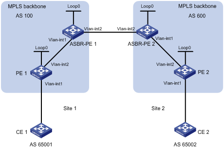
|
Device |
Interface |
IP address |
Device |
Interface |
IP address |
|
PE 1 |
Loop0 |
2.2.2.9/32 |
PE 2 |
Loop0 |
5.5.5.9/32 |
|
|
Vlan-int1 |
30.0.0.1/8 |
|
Vlan-int1 |
20.0.0.1/8 |
|
|
Vlan-int2 |
1.1.1.2/8 |
|
Vlan-int2 |
9.1.1.2/8 |
|
ASBR-PE 1 |
Loop0 |
3.3.3.9/32 |
ASBR-PE 2 |
Loop0 |
4.4.4.9/32 |
|
|
Vlan-int1 |
1.1.1.1/8 |
|
Vlan-int1 |
9.1.1.1/8 |
|
|
Vlan-int2 |
11.0.0.2/8 |
|
Vlan-int2 |
11.0.0.1/8 |
Configuration procedure
1. Configure PE 1.
# Run IS-IS on PE 1.
<PE1> system-view
[PE1] isis 1
[PE1-isis-1] network-entity 10.1111.1111.1111.1111.00
[PE1-isis-1] quit
# Configure LSR ID, enable MPLS and LDP.
[PE1] mpls lsr-id 2.2.2.9
[PE1] mpls
[PE1-mpls] quit
[PE1] mpls ldp
[PE1-mpls-ldp] quit
# Configure interface VLAN-interface 2, start IS-IS and enable MPLS and LDP on the interface.
[PE1] interface vlan-interface 2
[PE1-Vlan-interface2] ip address 1.1.1.2 255.0.0.0
[PE1-Vlan-interface2] isis enable 1
[PE1-Vlan-interface2] mpls
[PE1-Vlan-interface2] mpls ldp
[PE1-Vlan-interface2] quit
# Configure interface Loopback 0 and start IS-IS on it.
[PE1] interface loopback 0
[PE1-LoopBack0] ip address 2.2.2.9 32
[PE1-LoopBack0] isis enable 1
[PE1-LoopBack0] quit
# Create VPN instance vpn1 and configure the RD and VPN target attributes.
[PE1] ip vpn-instance vpn1
[PE1-vpn-instance-vpn1] route-distinguisher 11:11
[PE1-vpn-instance-vpn1] vpn-target 3:3 import-extcommunity
[PE1-vpn-instance-vpn1] vpn-target 3:3 export-extcommunity
[PE1-vpn-instance-vpn1] quit
# Bind the interface connected with CE 1 to the created VPN instance.
[PE1] interface vlan-interface 1
[PE1-Vlan-interface1] ip binding vpn-instance vpn1
[PE1-Vlan-interface1] ip address 30.0.0.1 8
[PE1-Vlan-interface1] quit
# Start BGP on PE 1.
[PE1] bgp 100
# Configure IBGP peer 3.3.3.9 as a VPNv4 peer.
[PE1-bgp] peer 3.3.3.9 as-number 100
[PE1-bgp] peer 3.3.3.9 connect-interface loopback 0
[PE1-bgp] ipv4-family vpnv4
[PE1-bgp-af-vpnv4] peer 3.3.3.9 enable
[PE1-bgp-af-vpnv4] quit
# Inject direct routes to the VPN routing table of vpn1.
[PE1-bgp] ipv4-family vpn-instance vpn1
[PE1-bgp-vpn1] import-route direct
[PE1-bgp-vpn1] quit
[PE1-bgp] quit
2. Configure ASBR-PE 1.
# Start IS-IS on ASBR-PE 1.
<ASBR-PE1> system-view
[ASBR-PE1] isis 1
[ASBR-PE1-isis-1] network-entity 10.2222.2222.2222.2222.00
[ASBR-PE1-isis-1] quit
# Configure LSR ID, enable MPLS and LDP.
[ASBR-PE1] mpls lsr-id 3.3.3.9
[ASBR-PE1] mpls
[ASBR-PE1-mpls] quit
[ASBR-PE1] mpls ldp
[ASBR-PE1-mpls-ldp] quit
# Configure interface VLAN-interface 1, start IS-IS and enable MPLS and LDP on the interface.
[ASBR-PE1] interface vlan-interface 1
[ASBR-PE1-Vlan-interface1] ip address 1.1.1.1 255.0.0.0
[ASBR-PE1-Vlan-interface1] isis enable 1
[ASBR-PE1-Vlan-interface1] mpls
[ASBR-PE1-Vlan-interface1] mpls ldp
[ASBR-PE1-Vlan-interface1] quit
# Configure interface VLAN-interface 2 and enable MPLS on it.
[ASBR-PE1] interface vlan-interface 2
[ASBR-PE1-Vlan-interface2] ip address 11.0.0.2 255.0.0.0
[ASBR-PE1-Vlan-interface2] mpls
[ASBR-PE1-Vlan-interface2] quit
# Configure interface Loopback 0 and start IS-IS on it.
[ASBR-PE1] interface loopback 0
[ASBR-PE1-LoopBack0] ip address 3.3.3.9 32
[ASBR-PE1-LoopBack0] isis enable 1
[ASBR-PE1-LoopBack0] quit
# Start BGP on ASBR-PE 1.
[ASBR-PE1] bgp 100
[ASBR-PE1-bgp] peer 2.2.2.9 as-number 100
[ASBR-PE1-bgp] peer 2.2.2.9 connect-interface loopback 0
[ASBR-PE1-bgp] peer 11.0.0.1 as-number 600
# Specify not to filter the received VPNv4 routes using the import target attribute.
[ASBR-PE1-bgp] ipv4-family vpnv4
[ASBR-PE1-bgp-af-vpnv4] undo policy vpn-target
# Configure both IBGP peer 2.2.2.0 and EBGP peer 11.0.0.1 as VPNv4 peers.
[ASBR-PE1-bgp-af-vpnv4] peer 11.0.0.1 enable
[ASBR-PE1-bgp-af-vpnv4] peer 2.2.2.9 enable
[ASBR-PE1-bgp-af-vpnv4] quit
3. Configure ASBR-PE 2.
# Start IS-IS on ASBR-PE 2.
<ASBR-PE2> system-view
[ASBR-PE2] isis 1
[ASBR-PE2-isis-1] network-entity 10.3333.3333.3333.3333.00
[ASBR-PE2-isis-1] quit
# Configure LSR ID, enable MPLS and LDP.
[ASBR-PE2] mpls lsr-id 4.4.4.9
[ASBR-PE2] mpls
[ASBR-PE2-mpls] quit
[ASBR-PE2] mpls ldp
[ASBR-PE2-mpls-ldp] quit
# Configure interface VLAN-interface 1, start IS-IS and enable MPLS and LDP on the interface.
[ASBR-PE2] interface vlan-interface 1
[ASBR-PE2-Vlan-interface1] ip address 9.1.1.1 255.0.0.0
[ASBR-PE2-Vlan-interface1] isis enable 1
[ASBR-PE2-Vlan-interface1] mpls
[ASBR-PE2-Vlan-interface1] mpls ldp
[ASBR-PE2-Vlan-interface1] quit
# Configure interface VLAN-interface 2 and enable MPLS on it.
[ASBR-PE2] interface vlan-interface 2
[ASBR-PE2-Vlan-interface2] ip address 11.0.0.1 255.0.0.0
[ASBR-PE2-Vlan-interface2] mpls
[ASBR-PE2-Vlan-interface2] quit
# Configure interface Loopback 0 and start IS-IS on it.
[ASBR-PE2] interface loopback 0
[ASBR-PE2-LoopBack0] ip address 4.4.4.9 32
[ASBR-PE2-LoopBack0] isis enable 1
[ASBR-PE2-LoopBack0] quit
# Start BGP on ASBR-PE 2.
[ASBR-PE2] bgp 600
[ASBR-PE2-bgp] peer 11.0.0.2 as-number 100
[ASBR-PE2-bgp] peer 5.5.5.9 as-number 600
[ASBR-PE2-bgp] peer 5.5.5.9 connect-interface loopback 0
# Specify not to filter the received VPNv4 routes using the import target attribute.
[ASBR-PE2-bgp] ipv4-family vpnv4
[ASBR-PE2-bgp-af-vpnv4] undo policy vpn-target
# Configure both IBGP peer 5.5.5.9 and EBGP peer 11.0.0.2 as VPNv4 peers.
[ASBR-PE2-bgp-af-vpnv4] peer 11.0.0.2 enable
[ASBR-PE2-bgp-af-vpnv4] peer 5.5.5.9 enable
[ASBR-PE2-bgp-af-vpnv4] quit
[ASBR-PE2-bgp] quit
4. Configure PE 2.
# Start IS-IS on PE 2.
<PE2> system-view
[PE2] isis 1
[PE2-isis-1] network-entity 10.4444.4444.4444.4444.00
[PE2-isis-1] quit
# Configure LSR ID, enable MPLS and LDP.
[PE2] mpls lsr-id 5.5.5.9
[PE2] mpls
[PE2-mpls] quit
[PE2] mpls ldp
[PE2-mpls-ldp] quit
# Configure interface VLAN-interface 2, start IS-IS and enable MPLS and LDP on the interface.
[PE2] interface vlan-interface 2
[PE2-Vlan-interface2] ip address 9.1.1.2 255.0.0.0
[PE2-Vlan-interface2] isis enable 1
[PE2-Vlan-interface2] mpls
[PE2-Vlan-interface2] mpls ldp
[PE2-Vlan-interface2] quit
# Configure interface Loopback 0 and start IS-IS on it.
[PE2] interface loopback 0
[PE2-LoopBack0] ip address 5.5.5.9 32
[PE2-LoopBack0] isis enable 1
[PE2-LoopBack0] quit
# Create VPN instance vpn1 and configure the RD and VPN target attributes.
[PE2] ip vpn-instance vpn1
[PE2-vpn-instance-vpn1] route-distinguisher 12:12
[PE2-vpn-instance-vpn1] vpn-target 3:3 import-extcommunity
[PE2-vpn-instance-vpn1] vpn-target 3:3 export-extcommunity
[PE2-vpn-instance-vpn1] quit
# Bind the interface connected with CE 2 to the created VPN instance.
[PE2] interface vlan-interface 1
[PE2-Vlan-interface1] ip binding vpn-instance vpn1
[PE2-Vlan-interface1] ip address 20.0.0.1 8
[PE2-Vlan-interface1] quit
# Start BGP on PE 2.
[PE2] bgp 600
# Configure IBGP peer 4.4.4.9 as a VPNv4 peer.
[PE2-bgp] peer 4.4.4.9 as-number 600
[PE2-bgp] peer 4.4.4.9 connect-interface loopback 0
[PE2-bgp] ipv4-family vpnv4
[PE2-bgp-af-vpnv4] peer 4.4.4.9 enable
[PE2-bgp-af-vpnv4] quit
# Inject direct routes to the VPN routing table of vpn1.
[PE2-bgp] ipv4-family vpn-instance vpn1
[PE2-bgp-vpn1] import-route direct
[PE2-bgp-vpn1] quit
[PE2-bgp] quit
5. Verify your configuration.
Ping PE 1 from PE 2 and ping PE 2 from PE 1. They can ping each other successfully.
[PE2] ping –vpn-instance vpn1 30.0.0.1
[PE1] ping –vpn-instance vpn1 20.0.0.1
Configuring inter-AS option C
Network requirements
· Site 1 and Site 2 belong to the same VPN. Site 1 accesses the network through PE 1 in AS 100 and Site 2 accesses the network through PE 2 in AS 600.
· PEs in the same AS runs IS-IS between them.
· PE 1 and ASBR-PE 1 exchange labeled IPv4 routes by MP-IBGP. PE 2 and ASBR-PE 2 exchange labeled IPv4 routes by MP-IBGP.
· PE 1 and PE 2 are MP-EBGP peers.
· ASBR-PE 1 and ASBR-PE 2 use their respective routing policies and label the routes received from each other.
· ASBR-PE 1 and ASBR-PE 2 use MP-EBGP to exchange labeled IPv4 routes.
Figure 25 Network diagram

|
Device |
Interface |
IP address |
Device |
Interface |
IP address |
|
PE 1 |
Loop0 |
2.2.2.9/32 |
PE 2 |
Loop0 |
5.5.5.9/32 |
|
|
Loop1 |
30.0.0.1/32 |
|
Loop1 |
20.0.0.1/32 |
|
|
Vlan-int1 |
1.1.1.2/8 |
|
Vlan-int1 |
9.1.1.2/8 |
|
ASBR-PE 1 |
Loop0 |
3.3.3.9/32 |
ASBR-PE 2 |
Loop0 |
4.4.4.9/32 |
|
|
Vlan-int1 |
1.1.1.1/8 |
|
Vlan-int1 |
9.1.1.1/8 |
|
|
Vlan-int2 |
11.0.0.2/8 |
|
Vlan-int2 |
11.0.0.1/8 |
Configuration procedure
1. Configure PE 1.
# Run IS-IS on PE 1.
<PE1> system-view
[PE1] isis 1
[PE1-isis-1] network-entity 10.1111.1111.1111.1111.00
[PE1-isis-1] quit
# Configure LSR ID, enable MPLS and LDP.
[PE1] mpls lsr-id 2.2.2.9
[PE1] mpls
[PE1-mpls] quit
[PE1] mpls ldp
[PE1-mpls-ldp] quit
# Configure interface VLAN-interface 1, start IS-IS and enable MPLS and LDP on the interface.
[PE1] interface vlan-interface 1
[PE1-Vlan-interface1] ip address 1.1.1.2 255.0.0.0
[PE1-Vlan-interface1] isis enable 1
[PE1-Vlan-interface1] mpls
[PE1-Vlan-interface1] mpls ldp
[PE1-Vlan-interface1] quit
# Configure interface Loopback 0 and start IS-IS on it.
[PE1] interface loopback 0
[PE1-LoopBack0] ip address 2.2.2.9 32
[PE1-LoopBack0] isis enable 1
[PE1-LoopBack0] quit
# Create VPN instance vpn1 and configure the RD and VPN target attributes.
[PE1] ip vpn-instance vpn1
[PE1-vpn-instance-vpn1] route-distinguisher 11:11
[PE1-vpn-instance-vpn1] vpn-target 3:3 import-extcommunity
[PE1-vpn-instance-vpn1] vpn-target 3:3 export-extcommunity
[PE1-vpn-instance-vpn1] quit
# Configure interface Loopback 1 and bind the interface to VPN instance vpn1.
[PE1] interface loopback 1
[PE1-LoopBack1] ip binding vpn-instance vpn1
[PE1-LoopBack1] ip address 30.0.0.1 32
[PE1-LoopBack1] quit
# Start BGP on PE 1.
[PE1] bgp 100
# Configure the capability to advertise labeled routes to IBGP peer 3.3.3.9 and to receive labeled routes from the peer.
[PE1-bgp] peer 3.3.3.9 as-number 100
[PE1-bgp] peer 3.3.3.9 connect-interface loopback 0
[PE1-bgp] peer 3.3.3.9 label-route-capability
# Configure the maximum hop count from PE 1 to EBGP peer 5.5.5.9 as 10.
[PE1-bgp] peer 5.5.5.9 as-number 600
[PE1-bgp] peer 5.5.5.9 connect-interface loopback 0
[PE1-bgp] peer 5.5.5.9 ebgp-max-hop 10
# Configure peer 5.5.5.9 as a VPNv4 peer.
[PE1-bgp] ipv4-family vpnv4
[PE1-bgp-af-vpnv4] peer 5.5.5.9 enable
[PE1-bgp-af-vpnv4] quit
# Inject direct routes to the routing table of vpn1.
[PE1-bgp] ipv4-family vpn-instance vpn1
[PE1-bgp-vpn1] import-route direct
[PE1-bgp-vpn1] quit
[PE1-bgp] quit
2. Configure ASBR-PE 1.
# Start IS-IS on ASBR-PE 1.
<ASBR-PE1> system-view
[ASBR-PE1] isis 1
[ASBR-PE1-isis-1] network-entity 10.2222.2222.2222.2222.00
[ASBR-PE1-isis-1] quit
# Configure LSR ID, enable MPLS and LDP.
[ASBR-PE1] mpls lsr-id 3.3.3.9
[ASBR-PE1] mpls
[ASBR-PE1-mpls] quit
[ASBR-PE1] mpls ldp
[ASBR-PE1-mpls-ldp] quit
# Configure interface VLAN-interface 1, start IS-IS and enable MPLS and LDP on the interface.
[ASBR-PE1] interface vlan-interface 1
[ASBR-PE1-Vlan-interface1] ip address 1.1.1.1 255.0.0.0
[ASBR-PE1-Vlan-interface1] isis enable 1
[ASBR-PE1-Vlan-interface1] mpls
[ASBR-PE1-Vlan-interface1] mpls ldp
[ASBR-PE1-Vlan-interface1] quit
# Configure interface VLAN-interface 2 and enable MPLS on it.
[ASBR-PE1] interface vlan-interface 2
[ASBR-PE1-Vlan-interface2] ip address 11.0.0.2 255.0.0.0
[ASBR-PE1-Vlan-interface2] mpls
[ASBR-PE1-Vlan-interface2] quit
# Configure interface Loopback 0 and start IS-IS on it.
[ASBR-PE1] interface loopback 0
[ASBR-PE1-LoopBack0] ip address 3.3.3.9 32
[ASBR-PE1-LoopBack0] isis enable 1
[ASBR-PE1-LoopBack0] quit
# Create routing policies.
[ASBR-PE1] route-policy policy1 permit node 1
[ASBR-PE1-route-policy1] apply mpls-label
[ASBR-PE1-route-policy1] quit
[ASBR-PE1] route-policy policy2 permit node 1
[ASBR-PE1-route-policy2] if-match mpls-label
[ASBR-PE1-route-policy2] apply mpls-label
[ASBR-PE1-route-policy2] quit
# Start BGP on ASBR-PE 1 and redistribute routes of IS-IS process 1.
[ASBR-PE1] bgp 100
[ASBR-PE1-bgp] import-route isis 1
# Apply routing policy policy2 to filter routes advertised to IBGP peer 2.2.2.9.
[ASBR-PE1-bgp] peer 2.2.2.9 as-number 100
[ASBR-PE1-bgp] peer 2.2.2.9 route-policy policy2 export
# Configure the capability to advertise labeled routes to and receive labeled routes from IBGP peer 2.2.2.9.
[ASBR-PE1-bgp] peer 2.2.2.9 connect-interface loopback 0
[ASBR-PE1-bgp] peer 2.2.2.9 label-route-capability
# Apply routing policy policy1 to filter routes advertised to EBGP peer 11.0.0.1.
[ASBR-PE1-bgp] peer 11.0.0.1 as-number 600
[ASBR-PE1-bgp] peer 11.0.0.1 route-policy policy1 export
# Configure the capability to advertise labeled routes to and receive labeled routes from EBGP peer 11.0.0.1.
[ASBR-PE1-bgp] peer 11.0.0.1 label-route-capability
[ASBR-PE1-bgp] quit
3. Configure ASBR-PE 2.
# Start IS-IS on ASBR-PE 2.
<ASBR-PE2> system-view
[ASBR-PE2] isis 1
[ASBR-PE2-isis-1] network-entity 10.3333.3333.3333.3333.00
[ASBR-PE2-isis-1] quit
# Configure LSR ID, enable MPLS and LDP.
[ASBR-PE2] mpls lsr-id 4.4.4.9
[ASBR-PE2] mpls
[ASBR-PE2-mpls] quit
[ASBR-PE2] mpls ldp
[ASBR-PE2-mpls-ldp] quit
# Configure interface VLAN-interface 1, start IS-IS and enable MPLS and LDP on the interface.
[ASBR-PE2] interface vlan-interface 1
[ASBR-PE2-Vlan-interface1] ip address 9.1.1.1 255.0.0.0
[ASBR-PE2-Vlan-interface1] isis enable 1
[ASBR-PE2-Vlan-interface1] mpls
[ASBR-PE2-Vlan-interface1] mpls ldp
[ASBR-PE2-Vlan-interface1] quit
# Configure interface Loopback 0 and start IS-IS on it.
[ASBR-PE2] interface loopback 0
[ASBR-PE2-LoopBack0] ip address 4.4.4.9 32
[ASBR-PE2-LoopBack0] isis enable 1
[ASBR-PE2-LoopBack0] quit
# Configure interface VLAN-interface 2 and enable MPLS on it.
[ASBR-PE2] interface vlan-interface 2
[ASBR-PE2-Vlan-interface2] ip address 11.0.0.1 255.0.0.0
[ASBR-PE2-Vlan-interface2] mpls
[ASBR-PE2-Vlan-interface2] quit
# Create routing policies.
[ASBR-PE2] route-policy policy1 permit node 1
New Sequence of this List
[ASBR-PE2-route-policy1] apply mpls-label
[ASBR-PE2-route-policy1] quit
[ASBR-PE2] route-policy policy2 permit node 1
[ASBR-PE2-route-policy2] if-match mpls-label
[ASBR-PE2-route-policy2] apply mpls-label
[ASBR-PE2-route-policy2] quit
# Start BGP on ASBR-PE 2 and redistribute routes of IS-IS process 1.
[ASBR-PE2] bgp 600
[ASBR-PE2-bgp] import-route isis 1
# Configure the capability to advertise labeled routes to and receive labeled routes from IBGP peer 5.5.5.9.
[ASBR-PE2-bgp] peer 5.5.5.9 as-number 600
[ASBR-PE2-bgp] peer 5.5.5.9 connect-interface loopback 0
[ASBR-PE2-bgp] peer 5.5.5.9 label-route-capability
# Apply routing policy policy2 to filter routes advertised to IBGP peer 5.5.5.9.
[ASBR-PE2-bgp] peer 5.5.5.9 route-policy policy2 export
# Apply routing policy policy1 to filter routes advertised to EBGP peer 11.0.0.2.
[ASBR-PE2-bgp] peer 11.0.0.2 as-number 100
[ASBR-PE2-bgp] peer 11.0.0.2 route-policy policy1 export
# Configure the capability to advertise labeled routes to and receive labeled routes from EBGP peer 11.0.0.2.
[ASBR-PE2-bgp] peer 11.0.0.2 label-route-capability
[ASBR-PE2-bgp] quit
4. Configure PE 2.
# Start IS-IS on PE 2.
<PE2> system-view
[PE2] isis 1
[PE2-isis-1] network-entity 10.4444.4444.4444.4444.00
[PE2-isis-1] quit
# Configure LSR ID, enable MPLS and LDP.
[PE2] mpls lsr-id 5.5.5.9
[PE2] mpls
[PE2-mpls] quit
[PE2] mpls ldp
[PE2-mpls-ldp] quit
# Configure interface VLAN-interface 1, start IS-IS and enable MPLS and LDP on the interface.
[PE2] interface vlan-interface 1
[PE2-Vlan-interface1] ip address 9.1.1.2 255.0.0.0
[PE2-Vlan-interface1] isis enable 1
[PE2-Vlan-interface1] mpls
[PE2-Vlan-interface1] mpls ldp
[PE2-Vlan-interface1] quit
# Configure interface Loopback 0 and start IS-IS on it.
[PE2] interface loopback 0
[PE2-LoopBack0] ip address 5.5.5.9 32
[PE2-LoopBack0] isis enable 1
[PE2-LoopBack0] quit
# Create VPN instance vpn1 and configure the RD and VPN target attributes.
[PE2] ip vpn-instance vpn1
[PE2-vpn-instance-vpn1] route-distinguisher 11:11
[PE2-vpn-instance-vpn1] vpn-target 3:3 import-extcommunity
[PE2-vpn-instance-vpn1] vpn-target 3:3 export-extcommunity
[PE2-vpn-instance-vpn1] quit
# Configure interface Loopback 1 and bind the interface to VPN instance vpn1.
[PE2] interface loopback 1
[PE2-LoopBack1] ip binding vpn-instance vpn1
[PE2-LoopBack1] ip address 20.0.0.1 32
[PE2-LoopBack1] quit
# Start BGP on PE 2.
[PE2] bgp 600
# Configure the capability to advertise labeled routes to IBGP peer 4.4.4.9 and to receive labeled routes from the peer.
[PE2-bgp] peer 4.4.4.9 as-number 600
[PE2-bgp] peer 4.4.4.9 connect-interface loopback 0
[PE2-bgp] peer 4.4.4.9 label-route-capability
# Configure the maximum hop count from PE 2 to EBGP peer 2.2.2.9 as 10.
[PE2-bgp] peer 2.2.2.9 as-number 100
[PE2-bgp] peer 2.2.2.9 connect-interface loopback 0
[PE2-bgp] peer 2.2.2.9 ebgp-max-hop 10
# Configure peer 2.2.2.9 as a VPNv4 peer.
[PE2-bgp] ipv4-family vpnv4
[PE2-bgp-af-vpnv4] peer 2.2.2.9 enable
[PE2-bgp-af-vpnv4] quit
# Redistribute direct routes to the routing table of vpn1.
[PE2-bgp] ipv4-family vpn-instance vpn1
[PE2-bgp-vpn1] import-route direct
[PE2-bgp-vpn1] quit
[PE2-bgp] quit
After you complete the previous configurations, PE 1 and PE 2 are able to ping each other:
[PE2] ping –vpn-instance vpn1 30.0.0.1
[PE1] ping –vpn-instance vpn1 20.0.0.1
Configuring carrier’s carrier in LDP mode
Network requirements
Configure carrier’s carrier for the scenario shown in Figure 26. In this scenario:
· PE 1 and PE 2 are the provider carrier’s PE switches. They provide VPN services for the customer carrier.
· CE 1 and CE 2 are the customer carrier’s switches. They are connected to the provider carrier’s backbone as CE switches.
· PE 3 and PE 4 are the customer carrier’s PE switches. They provide MPLS L3VPN services for the end customers.
· CE 3 and CE 4 are customers of the customer carrier.
The key to carrier’s carrier deployment is to configure exchange of two kinds of routes:
· Exchange of the customer carrier’s internal routes on the provider carrier’s backbone.
· Exchange of the end customers’ VPN routes between PE 3 and PE 4, the PEs of the customer carrier. In this process, an MP-IBGP peer relationship must be established between PE 3 and PE 4.

|
Interface |
IP address |
Device |
Interface |
IP address |
|
|
CE 3 |
Vlan-int1 |
100.1.1.1/24 |
CE 4 |
Vlan-int1 |
120.1.1.1/24 |
|
PE 3 |
Loop0 |
1.1.1.9/32 |
PE 4 |
Loop0 |
6.6.6.9/32 |
|
|
Vlan-int1 |
100.1.1.2/24 |
|
Vlan-int1 |
120.1.1.2/24 |
|
|
Vlan-int2 |
10.1.1.1/24 |
|
Vlan-int2 |
20.1.1.2/24 |
|
CE 1 |
Loop0 |
2.2.2.9/32 |
CE 2 |
Loop0 |
5.5.5.9/32 |
|
|
Vlan-int2 |
10.1.1.2/24 |
|
Vlan-int1 |
21.1.1.2/24 |
|
|
Vlan-int1 |
11.1.1.1/24 |
|
Vlan-int2 |
20.1.1.1/24 |
|
PE 1 |
Loop0 |
3.3.3.9/32 |
PE 2 |
Loop0 |
4.4.4.9/32 |
|
|
Vlan-int1 |
11.1.1.2/24 |
|
Vlan-int2 |
30.1.1.2/24 |
|
|
Vlan-int2 |
30.1.1.1/24 |
|
Vlan-int1 |
21.1.1.1/24 |
Configuration procedure
1. Configure MPLS L3VPN on the provider carrier backbone: start IS-IS as the IGP, enable LDP between PE 1 and PE 2, and establish an MP-IBGP peer relationship between the PEs.
# Configure PE 1.
<PE1> system-view
[PE1] interface loopback 0
[PE1-LoopBack0] ip address 3.3.3.9 32
[PE1-LoopBack0] quit
[PE1] mpls lsr-id 3.3.3.9
[PE1] mpls
[PE1-mpls] quit
[PE1] mpls ldp
[PE1-mpls-ldp] quit
[PE1] isis 1
[PE1-isis-1] network-entity 10.0000.0000.0000.0004.00
[PE1-isis-1] quit
[PE1] interface loopback 0
[PE1-LoopBack0] isis enable 1
[PE1-LoopBack0] quit
[PE1] interface vlan-interface 2
[PE1-Vlan-interface2] ip address 30.1.1.1 24
[PE1-Vlan-interface2] isis enable 1
[PE1-Vlan-interface2] mpls
[PE1-Vlan-interface2] mpls ldp
[PE1-Vlan-interface2] mpls ldp transport-address interface
[PE1-Vlan-interface2] quit
[PE1] bgp 100
[PE1-bgp] peer 4.4.4.9 as-number 100
[PE1-bgp] peer 4.4.4.9 connect-interface loopback 0
[PE1-bgp] ipv4-family vpnv4
[PE1-bgp-af-vpnv4] peer 4.4.4.9 enable
[PE1-bgp-af-vpnv4] quit
[PE1-bgp] quit
|
|
NOTE: The configurations for PE 2 are similar to those for PE 1. (Details not shown) |
After completing the previous configurations, do the following on PE 1 or PE 2:
? Execute the display mpls ldp session command to see whether the LDP session has been established successfully.
? Execute the display bgp peer command to see whether a BGP peer relationship has been established and is in Established state.
? Execute the display isis peer command to see whether an IS-IS neighbor relationship has been set up.
Take PE 1 as an example:
[PE1] display mpls ldp session
LDP Session(s) in Public Network
Total number of sessions: 1
----------------------------------------------------------------
Peer-ID Status LAM SsnRole FT MD5 KA-Sent/Rcv
----------------------------------------------------------------
4.4.4.9:0 Operational DU Active Off Off 378/378
----------------------------------------------------------------
LAM : Label Advertisement Mode FT : Fault Tolerance
[PE1] display bgp peer
BGP local router ID : 3.3.3.9
Local AS number : 100
Total number of peers : 1 Peers in established state : 1
Peer AS MsgRcvd MsgSent OutQ PrefRcv Up/Down State
4.4.4.9 100 162 145 0 0 02:12:47 Established
[PE1] display isis peer
Peer information for ISIS(1)
----------------------------
System Id: 0000.0000.0005
Interface: Vlan2 Circuit Id: 0000.0000.0001.01
State: Up HoldTime: 29s Type: L1(L1L2) PRI: --
System Id: 0000.0000.0005
Interface: Vlan2 Circuit Id: 0000.0000.0001.01
State: Up HoldTime: 29s Type: L2(L1L2) PRI: --
2. Configure the customer carrier network: start IS-IS as the IGP and enable LDP between PE 3 and CE 1, and between PE 4 and CE 2 respectively.
# Configure PE 3.
<PE3> system-view
[PE3] interface loopback 0
[PE3-LoopBack0] ip address 1.1.1.9 32
[PE3-LoopBack0] quit
[PE3] mpls lsr-id 1.1.1.9
[PE3] mpls
[PE3-mpls] quit
[PE3] mpls ldp
[PE3-mpls-ldp] quit
[PE3] isis 2
[PE3-isis-2] network-entity 10.0000.0000.0000.0001.00
[PE3-isis-2] quit
[PE3] interface loopback 0
[PE3-LoopBack0] isis enable 2
[PE3-LoopBack0] quit
[PE3] interface vlan-interface 2
[PE3-Vlan-interface2] ip address 10.1.1.1 24
[PE3-Vlan-interface2] isis enable 2
[PE3-Vlan-interface2] mpls
[PE3-Vlan-interface2] mpls ldp
[PE3-Vlan-interface2] mpls ldp transport-address interface
[PE3-Vlan-interface2] quit
# Configure CE 1.
<CE1> system-view
[CE1] interface loopback 0
[CE1-LoopBack0] ip address 2.2.2.9 32
[CE1-LoopBack0] quit
[CE1] mpls lsr-id 2.2.2.9
[CE1] mpls
[CE1-mpls] quit
[CE1] mpls ldp
[CE1-mpls-ldp] quit
[CE1] isis 2
[CE1-isis-2] network-entity 10.0000.0000.0000.0002.00
[CE1-isis-2] quit
[CE1] interface loopback 0
[CE1-LoopBack0] isis enable 2
[CE1-LoopBack0] quit
[CE1] interface vlan-interface 2
[CE1-Vlan-interface2] ip address 10.1.1.2 24
[CE1-Vlan-interface2] isis enable 2
[CE1-Vlan-interface2] mpls
[CE1-Vlan-interface2] mpls ldp
[CE1-Vlan-interface2] mpls ldp transport-address interface
[CE1-Vlan-interface2] quit
After you complete the previous configurations, PE 3 and CE 1 can establish an LDP session and IS-IS neighbor relationship between them.
|
|
NOTE: The configurations for PE 4 and CE 2 are similar to those for PE 3 and CE 1. (Details not shown) |
3. Perform configuration to allow CEs of the customer carrier to access PEs of the provider carrier, and redistribute IS-IS routes to BGP and BGP routes to IS-IS on the PEs.
# Configure PE 1 and inject IS-IS routes.
[PE1] ip vpn-instance vpn1
[PE1-vpn-instance-vpn1] route-distinguisher 200:1
[PE1-vpn-instance-vpn1] vpn-target 1:1
[PE1-vpn-instance-vpn1] quit
[PE1] mpls ldp vpn-instance vpn1
[PE1-mpls-ldp-vpn-instance-vpn1] quit
[PE1] isis 2 vpn-instance vpn1
[PE1-isis-2] network-entity 10.0000.0000.0000.0003.00
[PE1-isis-2] import-route bgp allow-ibgp
[PE1-isis-2] quit
[PE1] interface vlan-interface 1
[PE1-Vlan-interface1] ip binding vpn-instance vpn1
[PE1-Vlan-interface1] ip address 11.1.1.2 24
[PE1-Vlan-interface1] isis enable 2
[PE1-Vlan-interface1] mpls
[PE1-Vlan-interface1] mpls ldp
[PE1-Vlan-interface1] mpls ldp transport-address interface
[PE1-Vlan-interface1] quit
[PE1] bgp 100
[PE1-bgp] ipv4-family vpn-instance vpn1
[PE1-bgp-vpn1] import isis 2
[PE1-bgp-vpn1] quit
[PE1-bgp] quit
# Configure CE 1.
[CE1] interface vlan-interface 1
[CE1-Vlan-interface1] ip address 11.1.1.1 24
[CE1-Vlan-interface1] isis enable 2
[CE1-Vlan-interface1] mpls
[CE1-Vlan-interface1] mpls ldp
[CE1-Vlan-interface1] mpls ldp transport-address interface
[CE1-Vlan-interface1] quit
After you complete the previous configurations, PE 1 and CE 1 can establish an LDP session and IS-IS neighbor relationship between them.
|
|
NOTE: The configurations for PE 2 and CE 2 are similar to those for PE 1 and CE 1. (Details not shown) |
4. Perform configuration to allow CEs of customers to access the PEs of the customer carrier.
# Configure CE 3.
<CE3> system-view
[CE3] interface vlan-interface 1
[CE3-Vlan-interface1] ip address 100.1.1.1 24
[CE3-Vlan-interface1] quit
[CE3] bgp 65410
[CE3-bgp] peer 100.1.1.2 as-number 100
[CE3-bgp] import-route direct
[CE3-bgp] quit
# Configure PE 3.
[PE3] ip vpn-instance vpn1
[PE3-vpn-instance-vpn1] route-distinguisher 100:1
[PE3-vpn-instance-vpn1] vpn-target 1:1
[PE3-vpn-instance-vpn1] quit
[PE3] interface vlan-interface 1
[PE3-Vlan-interface1] ip binding vpn-instance vpn1
[PE3-Vlan-interface1] ip address 100.1.1.2 24
[PE3-Vlan-interface1] quit
[PE3] bgp 100
[PE3-bgp] ipv4-family vpn-instance vpn1
[PE3-bgp-vpn1] peer 100.1.1.1 as-number 65410
[PE3-bgp-vpn1] import-route direct
[PE3-bgp-vpn1] quit
[PE3-bgp] quit
|
|
NOTE: The configurations for PE 4 and CE 4 are similar to those for PE 3 and CE 3. (Details not shown) |
5. Configure an MP-IBGP peer relationship between the PEs of the customer carrier to exchange the VPN routes of the customer carrier customers.
# Configure PE 3.
[PE3] bgp 100
[PE3-bgp] peer 6.6.6.9 as-number 100
[PE3-bgp] peer 6.6.6.9 connect-interface loopback 0
[PE3-bgp] ipv4-family vpnv4
[PE3-bgp-af-vpnv4] peer 6.6.6.9 enable
[PE3-bgp-af-vpnv4] quit
[PE3-bgp] quit
|
|
NOTE: The configurations for PE 4 are similar to those for PE 3. (Details not shown) |
6. Verify your configuration.
Issue the display ip routing-table command on PE 1 and PE 2. You will see that only routes of the provider carrier network are present in the public network routing table of PE 1 and PE 2. Take PE 1 as an example:
[PE1] display ip routing-table
Routing Tables: Public
Destinations : 7 Routes : 7
Destination/Mask Proto Pre Cost NextHop Interface
3.3.3.9/32 Direct 0 0 127.0.0.1 InLoop0
4.4.4.9/32 ISIS 15 10 30.1.1.2 Vlan2
30.1.1.0/24 Direct 0 0 30.1.1.1 Vlan2
30.1.1.1/32 Direct 0 0 127.0.0.1 InLoop0
30.1.1.2/32 Direct 0 0 30.1.1.2 Vlan2
127.0.0.0/8 Direct 0 0 127.0.0.1 InLoop0
127.0.0.1/32 Direct 0 0 127.0.0.1 InLoop0
Issuing the display ip routing-table vpn-instance command on PE 1 and PE 2, you will see that the internal routes of the customer carrier network are present in the VPN routing tables, but the VPN routes that the customer carrier maintains are not. Take PE 1 as an example:
[PE1] display ip routing-table vpn-instance vpn1
Routing Tables: vpn1
Destinations : 11 Routes : 11
Destination/Mask Proto Pre Cost NextHop Interface
1.1.1.9/32 ISIS 15 20 11.1.1.1 Vlan1
2.2.2.9/32 ISIS 15 10 11.1.1.1 Vlan1
5.5.5.9/32 BGP 255 0 4.4.4.9 NULL0
6.6.6.9/32 BGP 255 0 4.4.4.9 NULL0
10.1.1.0/24 ISIS 15 20 11.1.1.1 Vlan1
11.1.1.0/24 Direct 0 0 11.1.1.1 Vlan1
11.1.1.1/32 Direct 0 0 127.0.0.1 InLoop0
11.1.1.2/32 Direct 0 0 11.1.1.2 Vlan1
20.1.1.0/24 BGP 255 0 4.4.4.9 NULL0
21.1.1.0/24 BGP 255 0 4.4.4.9 NULL0
21.1.1.2/32 BGP 255 0 4.4.4.9 NULL0
Issuing the display ip routing-table command on CE 1 and CE 2, you will see that the internal routes of the customer carrier network are present in the public network routing tables, but the VPN routes that the customer carrier maintains are not. Take CE 1 as an example:
[CE1] display ip routing-table
Routing Tables: Public
Destinations : 16 Routes : 16
Destination/Mask Proto Pre Cost NextHop Interface
1.1.1.9/32 ISIS 15 10 10.1.1.2 Vlan2
2.2.2.9/32 Direct 0 0 127.0.0.1 InLoop0
5.5.5.9/32 ISIS 15 74 11.1.1.2 Vlan1
6.6.6.9/32 ISIS 15 74 11.1.1.2 Vlan1
10.1.1.0/24 Direct 0 0 10.1.1.2 Vlan2
10.1.1.1/32 Direct 0 0 10.1.1.1 Vlan2
10.1.1.2/32 Direct 0 0 127.0.0.1 InLoop0
11.1.1.0/24 Direct 0 0 11.1.1.1 Vlan1
11.1.1.1/32 Direct 0 0 127.0.0.1 InLoop0
11.1.1.2/32 Direct 0 0 11.1.1.2 Vlan1
20.1.1.0/24 ISIS 15 74 11.1.1.2 Vlan1
21.1.1.0/24 ISIS 15 74 11.1.1.2 Vlan1
21.1.1.2/32 ISIS 15 74 11.1.1.2 Vlan1
127.0.0.0/8 Direct 0 0 127.0.0.1 InLoop0
127.0.0.1/32 Direct 0 0 127.0.0.1 InLoop0
Issuing the display ip routing-table command on PE 3 and PE 4, you will see that the internal routes of the customer carrier network are present in the public network routing tables. Take PE 3 as an example:
[PE3] display ip routing-table
Routing Tables: Public
Destinations : 11 Routes : 11
Destination/Mask Proto Pre Cost NextHop Interface
1.1.1.9/32 Direct 0 0 127.0.0.1 InLoop0
2.2.2.9/32 ISIS 15 10 10.1.1.2 Vlan2
5.5.5.9/32 ISIS 15 84 10.1.1.2 Vlan2
6.6.6.9/32 ISIS 15 84 10.1.1.2 Vlan2
10.1.1.0/24 Direct 0 0 10.1.1.1 Vlan2
10.1.1.1/32 Direct 0 0 127.0.0.1 InLoop0
10.1.1.2/32 Direct 0 0 10.1.1.2 Vlan2
11.1.1.0/24 ISIS 15 20 10.1.1.2 Vlan2
20.1.1.0/24 ISIS 15 84 10.1.1.2 Vlan2
21.1.1.0/24 ISIS 15 84 10.1.1.2 Vlan2
21.1.1.2/32 ISIS 15 84 10.1.1.2 Vlan2
127.0.0.0/8 Direct 0 0 127.0.0.1 InLoop0
127.0.0.1/32 Direct 0 0 127.0.0.1 InLoop0
Issuing the display ip routing-table vpn-instance command on PE 3 and PE 4, you will see that the routes of the remote VPN customers are present in the VPN routing tables. Take PE 3 as an example:
[PE3] display ip routing-table vpn-instance vpn1
Routing Tables: vpn1
Destinations : 3 Routes : 3
Destination/Mask Proto Pre Cost NextHop Interface
100.1.1.0/24 Direct 0 0 100.1.1.2 Vlan1
100.1.1.2/32 Direct 0 0 127.0.0.1 InLoop0
120.1.1.0/24 BGP 255 0 6.6.6.9 NULL0
PE 3 and PE 4 can ping each other:
[PE3] ping 20.1.1.2
PING 20.1.1.2: 56 data bytes, press CTRL_C to break
Reply from 20.1.1.2: bytes=56 Sequence=1 ttl=252 time=127 ms
Reply from 20.1.1.2: bytes=56 Sequence=2 ttl=252 time=97 ms
Reply from 20.1.1.2: bytes=56 Sequence=3 ttl=252 time=83 ms
Reply from 20.1.1.2: bytes=56 Sequence=4 ttl=252 time=70 ms
Reply from 20.1.1.2: bytes=56 Sequence=5 ttl=252 time=60 ms
--- 20.1.1.2 ping statistics ---
5 packet(s) transmitted
5 packet(s) received
0.00% packet loss
round-trip min/avg/max = 60/87/127 ms
CE 3 and CE 4 can ping each other:
[CE3] ping 120.1.1.1
PING 120.1.1.1: 56 data bytes, press CTRL_C to break
Reply from 120.1.1.1: bytes=56 Sequence=1 ttl=252 time=102 ms
Reply from 120.1.1.1: bytes=56 Sequence=2 ttl=252 time=69 ms
Reply from 120.1.1.1: bytes=56 Sequence=3 ttl=252 time=105 ms
Reply from 120.1.1.1: bytes=56 Sequence=4 ttl=252 time=88 ms
Reply from 120.1.1.1: bytes=56 Sequence=5 ttl=252 time=87 ms
--- 120.1.1.1 ping statistics ---
5 packet(s) transmitted
5 packet(s) received
0.00% packet loss
round-trip min/avg/max = 69/90/105 ms
Configuring carrier’s carrier in BGP mode
Network requirements
Configure carrier’s carrier for the scenario shown in Figure 27. In this scenario:
· PE 1 and PE 2 are the provider carrier’s PE switches. They provide VPN services for the customer carrier.
· CE 1 and CE 2 are the customer carrier’s switches. They are connected to the provider carrier’s backbone as CE switches.
· PE 3 and PE 4 are the customer carrier’s PE switches. They provide MPLS L3VPN services for the end customers.
· CE 3 and CE 4 are customers of the customer carrier.
The key to carrier’s carrier deployment is to configure exchange of two kinds of routes:
· Exchange of the customer carrier’s internal routes on the provider carrier’s backbone.
· Exchange of the end customers’ VPN routes between PE 3 and PE 4, the PEs of the customer carrier. In this process, an MP-IBGP peer relationship must be established between PE 3 and PE 4.
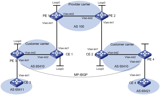
|
Device |
Interface |
IP address |
Device |
Interface |
IP address |
|
CE 3 |
Vlan-int1 |
100.1.1.1/24 |
CE 4 |
Vlan-int1 |
120.1.1.1/24 |
|
PE 3 |
Loop0 |
1.1.1.9/32 |
PE 4 |
Loop0 |
6.6.6.9/32 |
|
|
Vlan-int1 |
100.1.1.2/24 |
|
Vlan-int1 |
120.1.1.2/24 |
|
|
Vlan-int2 |
10.1.1.1/24 |
|
Vlan-int2 |
20.1.1.2/24 |
|
CE 1 |
Loop0 |
2.2.2.9/32 |
CE 2 |
Loop0 |
5.5.5.9/32 |
|
|
Vlan-int2 |
10.1.1.2/24 |
|
Vlan-int1 |
21.1.1.2/24 |
|
|
Vlan-int1 |
11.1.1.1/24 |
|
Vlan-int2 |
20.1.1.1/24 |
|
PE 1 |
Loop0 |
3.3.3.9/32 |
PE 2 |
Loop0 |
4.4.4.9/32 |
|
|
Vlan-int1 |
11.1.1.2/24 |
|
Vlan-int2 |
30.1.1.2/24 |
|
|
Vlan-int2 |
30.1.1.1/24 |
|
Vlan-int1 |
21.1.1.1/24 |
Configuration procedure
1. Configure MPLS L3VPN on the provider carrier backbone: start IS-IS as the IGP, enable LDP between PE 1 and PE 2, and establish an MP-IBGP peer relationship between the PEs.
# Configure PE 1.
<PE1> system-view
[PE1] interface loopback 0
[PE1-LoopBack0] ip address 3.3.3.9 32
[PE1-LoopBack0] quit
[PE1] mpls lsr-id 3.3.3.9
[PE1] mpls
[PE1-mpls] quit
[PE1] mpls ldp
[PE1-mpls-ldp] quit
[PE1] isis 1
[PE1-isis-1] network-entity 10.0000.0000.0000.0004.00
[PE1-isis-1] quit
[PE1] interface loopback 0
[PE1-LoopBack0] isis enable 1
[PE1-LoopBack0] quit
[PE1] interface vlan-interface 2
[PE1-Vlan-interface2] ip address 30.1.1.1 24
[PE1-Vlan-interface2] isis enable 1
[PE1-Vlan-interface2] mpls
[PE1-Vlan-interface2] mpls ldp
[PE1-Vlan-interface2] mpls ldp transport-address interface
[PE1-Vlan-interface2] quit
[PE1] bgp 100
[PE1-bgp] peer 4.4.4.9 as-number 100
[PE1-bgp] peer 4.4.4.9 connect-interface loopback 0
[PE1-bgp] ipv4-family vpnv4
[PE1-bgp-af-vpnv4] peer 4.4.4.9 enable
[PE1-bgp-af-vpnv4] quit
[PE1-bgp] quit
|
|
NOTE: The configurations for PE 2 are similar to those for PE 1. (Details not shown) |
After completing the previous configurations, do the following on PE 1 or PE 2:
? Execute the display mpls ldp session command to see whether the LDP session has been established successfully.
? Execute the display bgp peer command to see whether a BGP peer relationship has been established and is in state Established.
? Execute the display isis peer command to see whether an IS-IS neighbor relationship has been set up.
Take PE 1 as an example:
[PE1] display mpls ldp session
LDP Session(s) in Public Network
Total number of sessions: 1
----------------------------------------------------------------
Peer-ID Status LAM SsnRole FT MD5 KA-Sent/Rcv
----------------------------------------------------------------
4.4.4.9:0 Operational DU Active Off Off 378/378
----------------------------------------------------------------
LAM : Label Advertisement Mode FT : Fault Tolerance
[PE1] display bgp peer
BGP local router ID : 3.3.3.9
Local AS number : 100
Total number of peers : 1 Peers in established state : 1
Peer AS MsgRcvd MsgSent OutQ PrefRcv Up/Down State
4.4.4.9 100 162 145 0 0 02:12:47 Established
[PE1] display isis peer
Peer information for ISIS(1)
----------------------------
System Id: 0000.0000.0005
Interface: Vlan2 Circuit Id: 0000.0000.0001.01
State: Up HoldTime: 29s Type: L1(L1L2) PRI: --
System Id: 0000.0000.0005
Interface: Vlan2 Circuit Id: 0000.0000.0001.01
State: Up HoldTime: 29s Type: L2(L1L2) PRI: --
2. Configure the customer carrier networks: start IS-IS as the IGP and enable LDP between PE 3 and CE 1, and between PE 4 and CE 2 respectively.
# Configure PE 3.
<PE3> system-view
[PE3] interface loopback 0
[PE3-LoopBack0] ip address 1.1.1.9 32
[PE3-LoopBack0] quit
[PE3] mpls lsr-id 1.1.1.9
[PE3] mpls
[PE3-mpls] quit
[PE3] mpls ldp
[PE3-mpls-ldp] quit
[PE3] isis 2
[PE3-isis-2] network-entity 10.0000.0000.0000.0001.00
[PE3-isis-2] quit
[PE3] interface loopback 0
[PE3-LoopBack0] isis enable 2
[PE3-LoopBack0] quit
[PE3] interface vlan-interface 2
[PE3-Vlan-interface2] ip address 10.1.1.1 24
[PE3-Vlan-interface2] isis enable 2
[PE3-Vlan-interface2] mpls
[PE3-Vlan-interface2] mpls ldp
[PE3-Vlan-interface2] mpls ldp transport-address interface
[PE3-Vlan-interface2] quit
# Configure CE 1.
<CE1> system-view
[CE1] interface loopback 0
[CE1-LoopBack0] ip address 2.2.2.9 32
[CE1-LoopBack0] quit
[CE1] mpls lsr-id 2.2.2.9
[CE1] mpls
[CE1-mpls] quit
[CE1] mpls ldp
[CE1-mpls-ldp] quit
[CE1] isis 2
[CE1-isis-2] network-entity 10.0000.0000.0000.0002.00
[CE1-isis-2] quit
[CE1] interface loopback 0
[CE1-LoopBack0] isis enable 2
[CE1-LoopBack0] quit
[CE1] interface vlan-interface 2
[CE1-Vlan-interface2] ip address 10.1.1.2 24
[CE1-Vlan-interface2] isis enable 2
[CE1-Vlan-interface2] mpls
[CE1-Vlan-interface2] mpls ldp
[CE1-Vlan-interface2] mpls ldp transport-address interface
[CE1-Vlan-interface2] quit
After you complete the previous configurations, PE 3 and CE 1 can establish an LDP session and IS-IS neighbor relationship between them.
|
|
NOTE: The configurations for PE 4 and CE 2 are similar to those for PE 3 and CE 1. (Details not shown) |
3. Connect CEs of the customer carriers to PEs of the provider carrier.
# Configure PE 1.
[PE1] route-policy policy1 permit node 10
[PE1-route-policy] apply mpls-label
[PE1] ip vpn-instance vpn1
[PE1-vpn-instance-vpn1] route-distinguisher 200:1
[PE1-vpn-instance-vpn1] vpn-target 1:1
[PE1-vpn-instance-vpn1] quit
[PE1] interface vlan-interface1
[PE1-Vlan-interface1] ip binding vpn-instance vpn1
[PE1-Vlan-interface1] ip address 11.1.1.2 24
[PE1-Vlan-interface1] mpls
[PE1-Vlan-interface1] quit
[PE1] bgp 100
[PE1-bgp] ipv4-family vpn-instance vpn1
[PE1-bgp-vpn1] import direct
[PE1-bgp-vpn1] peer 11.1.1.1 as-number 65410
[PE1-bgp-vpn1] peer 11.1.1.1 route-policy policy1 export
[PE1-bgp-vpn1] peer 11.1.1.1 label-route-capability
[PE1-bgp-vpn1] peer 11.1.1.1 substitute-as
[PE1-bgp-vpn1] quit
[PE1-bgp] quit
# Configure CE 1.
[CE1] route-policy policy1 permit node 10
[CE1-route-policy] apply mpls-label
[CE1] interface vlan-interface1
[CE1-Vlan-interface1] ip address 11.1.1.1 24
[CE1-Vlan-interface1] mpls
[CE1-Vlan-interface1] quit
[CE1] bgp 65410
[CE1-bgp] import-route direct
[CE1-bgp] import-route isis 2
[CE1-bgp] peer 11.1.1.2 as-number 100
[CE1-bgp] peer 11.1.1.2 route-policy policy1 export
[CE1-bgp] peer 11.1.1.2 label-route-capability
[CE1-bgp] quit
After you complete the previous configurations, PE 1 and CE 1 can establish a BGP neighbor relationship between them.
|
|
NOTE: The configurations for PE 2 and CE 2 are similar to those for PE 1 and CE 1. (Details not shown) |
4. Connect CEs of customers to the PEs of the customer carriers.
# Configure CE 3.
<CE3> system-view
[CE3] interface vlan-interface1
[CE3-Vlan-interface1] ip address 100.1.1.1 24
[CE3-Vlan-interface1] quit
[CE3] bgp 65411
[CE3-bgp] peer 100.1.1.2 as-number 65410
[CE3-bgp] import-route direct
[CE3-bgp] quit
# Configure PE 3.
[PE3] ip vpn-instance vpn1
[PE3-vpn-instance-vpn1] route-distinguisher 100:1
[PE3-vpn-instance-vpn1] vpn-target 1:1
[PE3-vpn-instance-vpn1] quit
[PE3] interface Vlan-interface1
[PE3-Vlan-interface1] ip binding vpn-instance vpn1
[PE3-Vlan-interface1] ip address 100.1.1.2 24
[PE3-Vlan-interface1] quit
[PE3] bgp 65410
[PE3-bgp] ipv4-family vpn-instance vpn1
[PE3-bgp-vpn1] peer 100.1.1.1 as-number 65411
[PE3-bgp-vpn1] import-route direct
[PE3-bgp-vpn1] quit
[PE3-bgp] quit
|
|
NOTE: The configurations for PE 4 and CE 4 are similar to those for PE 3 and CE 3. (Details not shown) |
5. Configure a MP-IBGP peer relationship between PEs of the customer carriers to exchange the VPN routes of the customers of the customer carriers.
# Configure PE 3.
[PE3] bgp 65410
[PE3-bgp] peer 6.6.6.9 as-number 65410
[PE3-bgp] peer 6.6.6.9 connect-interface loopback 0
[PE3-bgp] ipv4-family vpnv4
[PE3-bgp-af-vpnv4] peer 6.6.6.9 enable
[PE3-bgp-af-vpnv4] quit
[PE3-bgp] quit
|
|
NOTE: The configurations for PE 4 are similar to those for PE 3. (Details not shown) |
6. Verify the configuration.
Execute the display ip routing-table command on PE 1 and PE 2. You can see that only routes of the provider carrier network are present in the public network routing tables of PE 1 and PE 2. Take PE 1 as an example:
[PE1] display ip routing-table
Routing Tables: Public
Destinations : 7 Routes : 7
Destination/Mask Proto Pre Cost NextHop Interface
3.3.3.9/32 Direct 0 0 127.0.0.1 InLoop0
4.4.4.9/32 ISIS 15 10 30.1.1.2 Vlan2
30.1.1.0/24 Direct 0 0 30.1.1.1 Vlan2
30.1.1.1/32 Direct 0 0 127.0.0.1 InLoop0
30.1.1.2/32 Direct 0 0 30.1.1.2 Vlan2
127.0.0.0/8 Direct 0 0 127.0.0.1 InLoop0
127.0.0.1/32 Direct 0 0 127.0.0.1 InLoop0
Execute the display ip routing-table vpn-instance command on PE 1 and PE 2. You see that the internal routes of the customer carrier networks are present in the VPN routing tables, but the VPN routes that the customer carriers maintain are not. Take PE 1 as an example:
[PE1] display ip routing-table vpn-instance vpn1
Routing Tables: vpn1
Destinations : 11 Routes : 11
Destination/Mask Proto Pre Cost NextHop Interface
1.1.1.9/32 ISIS 15 20 11.1.1.1 Vlan1
2.2.2.9/32 ISIS 15 10 11.1.1.1 Vlan1
5.5.5.9/32 BGP 255 0 4.4.4.9 NULL0
6.6.6.9/32 BGP 255 0 4.4.4.9 NULL0
10.1.1.0/24 ISIS 15 20 11.1.1.1 Vlan1
11.1.1.0/24 Direct 0 0 11.1.1.1 Vlan1
11.1.1.1/32 Direct 0 0 127.0.0.1 InLoop0
11.1.1.2/32 Direct 0 0 11.1.1.2 Vlan1
20.1.1.0/24 BGP 255 0 4.4.4.9 NULL0
21.1.1.0/24 BGP 255 0 4.4.4.9 NULL0
21.1.1.2/32 BGP 255 0 4.4.4.9 NULL0
Execute the display ip routing-table command on CE 1 and CE 2. You see that the internal routes of the customer carrier networks are present in the public network routing tables, but the VPN routes that the customer carriers maintain are not. Take CE 1 as an example:
[CE1] display ip routing-table
Routing Tables: Public
Destinations : 16 Routes : 16
Destination/Mask Proto Pre Cost NextHop Interface
1.1.1.9/32 ISIS 15 10 10.1.1.2 Vlan2
2.2.2.9/32 Direct 0 0 127.0.0.1 InLoop0
5.5.5.9/32 ISIS 15 74 11.1.1.2 Vlan1
6.6.6.9/32 ISIS 15 74 11.1.1.2 Vlan1
10.1.1.0/24 Direct 0 0 10.1.1.2 Vlan2
10.1.1.1/32 Direct 0 0 10.1.1.1 Vlan2
10.1.1.2/32 Direct 0 0 127.0.0.1 InLoop0
11.1.1.0/24 Direct 0 0 11.1.1.1 Vlan1
11.1.1.1/32 Direct 0 0 127.0.0.1 InLoop0
11.1.1.2/32 Direct 0 0 11.1.1.2 Vlan1
20.1.1.0/24 ISIS 15 74 11.1.1.2 Vlan1
21.1.1.0/24 ISIS 15 74 11.1.1.2 Vlan1
21.1.1.2/32 ISIS 15 74 11.1.1.2 Vlan1
127.0.0.0/8 Direct 0 0 127.0.0.1 InLoop0
127.0.0.1/32 Direct 0 0 127.0.0.1 InLoop0
Execute the display ip routing-table command on PE 3 and PE 4. You see that the internal routes of the customer carrier networks are present in the public network routing tables. Take PE 3 as an example:
[PE3] display ip routing-table
Routing Tables: Public
Destinations : 11 Routes : 11
Destination/Mask Proto Pre Cost NextHop Interface
1.1.1.9/32 Direct 0 0 127.0.0.1 InLoop0
2.2.2.9/32 ISIS 15 10 10.1.1.2 Vlan2
5.5.5.9/32 ISIS 15 84 10.1.1.2 Vlan2
6.6.6.9/32 ISIS 15 84 10.1.1.2 Vlan2
10.1.1.0/24 Direct 0 0 10.1.1.1 Vlan2
10.1.1.1/32 Direct 0 0 127.0.0.1 InLoop0
10.1.1.2/32 Direct 0 0 10.1.1.2 Vlan2
11.1.1.0/24 ISIS 15 20 10.1.1.2 Vlan2
20.1.1.0/24 ISIS 15 84 10.1.1.2 Vlan2
21.1.1.0/24 ISIS 15 84 10.1.1.2 Vlan2
21.1.1.2/32 ISIS 15 84 10.1.1.2 Vlan2
127.0.0.0/8 Direct 0 0 127.0.0.1 InLoop0
127.0.0.1/32 Direct 0 0 127.0.0.1 InLoop0
Execute the display ip routing-table vpn-instance command on PE 3 and PE 4. You see that the routes of the remote VPN customers are present in the VPN routing tables. Take PE 3 as an example:
[PE3] display ip routing-table vpn-instance vpn1
Routing Tables: vpn1
Destinations : 3 Routes : 3
Destination/Mask Proto Pre Cost NextHop Interface
100.1.1.0/24 Direct 0 0 100.1.1.2 Vlan1
100.1.1.2/32 Direct 0 0 127.0.0.1 InLoop0
120.1.1.0/24 BGP 255 0 6.6.6.9 NULL0
PE 3 and PE 4 can ping each other:
[PE3] ping 20.1.1.2
PING 20.1.1.2: 56 data bytes, press CTRL_C to break
Reply from 20.1.1.2: bytes=56 Sequence=1 ttl=252 time=127 ms
Reply from 20.1.1.2: bytes=56 Sequence=2 ttl=252 time=97 ms
Reply from 20.1.1.2: bytes=56 Sequence=3 ttl=252 time=83 ms
Reply from 20.1.1.2: bytes=56 Sequence=4 ttl=252 time=70 ms
Reply from 20.1.1.2: bytes=56 Sequence=5 ttl=252 time=60 ms
--- 20.1.1.2 ping statistics ---
5 packet(s) transmitted
5 packet(s) received
0.00% packet loss
round-trip min/avg/max = 60/87/127 ms
CE 3 and CE 4 can ping each other:
[CE3] ping 120.1.1.1
PING 120.1.1.1: 56 data bytes, press CTRL_C to break
Reply from 120.1.1.1: bytes=56 Sequence=1 ttl=252 time=102 ms
Reply from 120.1.1.1: bytes=56 Sequence=2 ttl=252 time=69 ms
Reply from 120.1.1.1: bytes=56 Sequence=3 ttl=252 time=105 ms
Reply from 120.1.1.1: bytes=56 Sequence=4 ttl=252 time=88 ms
Reply from 120.1.1.1: bytes=56 Sequence=5 ttl=252 time=87 ms
--- 120.1.1.1 ping statistics ---
5 packet(s) transmitted
5 packet(s) received
0.00% packet loss
round-trip min/avg/max = 69/90/105 ms
Configuring nested VPN
Network requirements
The service provider provides nested VPN services for users, as shown in Figure 28, where:
· PE 1 and PE 2 are PE switches on the service provider backbone. Both of them support the nested VPN function.
· CE 1 and CE 2 are connected to the service provider backbone. Both of them support VPNv4 routes.
· PE 3 and PE 4 are PE switches of the customer VPN. Both of them support MPLS L3VPN.
· CE 3 through CE 6 are CE switches of the sub-VPNs for the customer VPN.
The key of nested VPN configuration is to understand the processing of routes of sub-VPNs on the service provider PEs, which is described as follows:
· When receiving a VPNv4 route from a CE (CE 1 or CE 2 in this example), a service provider PE replaces the RD of the VPNv4 route with the RD of the MPLS VPN on the service provider network where the CE resides, adds the export target attribute of the MPLS VPN on the service provider network to the extended community attribute list, and then forwards the VPNv4 route as usual.
· To implement exchange of sub-VPN routes between customer PEs and service provider PEs, MP-EBGP peers should be established between service provider PEs and customer CEs.
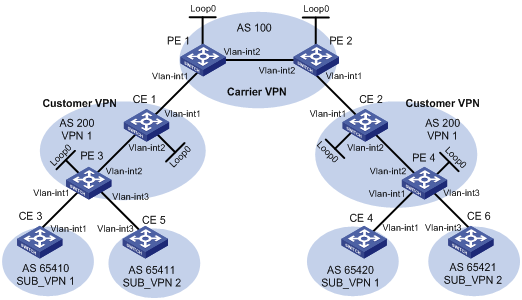
|
Device |
Interface |
IP address |
Device |
Interface |
IP address |
|
CE 1 |
Loop0 |
2.2.2.9/32 |
CE 2 |
Loop0 |
5.5.5.9/32 |
|
|
Vlan-int2 |
10.1.1.2/24 |
|
Vlan-int1 |
21.1.1.2/24 |
|
|
Vlan-int1 |
11.1.1.1/24 |
|
Vlan-int2 |
20.1.1.1/24 |
|
CE 3 |
Vlan-int1 |
100.1.1.1/24 |
CE 4 |
Vlan-int1 |
120.1.1.1/24 |
|
CE 5 |
Vlan-int3 |
110.1.1.1/24 |
CE 6 |
Vlan-int3 |
130.1.1.1/24 |
|
PE 1 |
Loop0 |
3.3.3.9/32 |
PE 2 |
Loop0 |
4.4.4.9/32 |
|
|
Vlan-int1 |
11.1.1.2/24 |
|
Vlan-int1 |
21.1.1.1/24 |
|
|
Vlan-int2 |
30.1.1.1/24 |
|
Vlan-int2 |
30.1.1.2/24 |
|
PE 3 |
Loop0 |
1.1.1.9/32 |
PE 4 |
Loop0 |
6.6.6.9/32 |
|
|
Vlan-int1 |
100.1.1.2/24 |
|
Vlan-int1 |
120.1.1.2/24 |
|
|
Vlan-int2 |
10.1.1.1/24 |
|
Vlan-int2 |
20.1.1.2/24 |
|
|
Vlan-int3 |
110.1.1.2/24 |
|
Vlan-int3 |
130.1.1.2/24 |
Configuration procedure
1. Configure MPLS L3VPN on the service provider backbone, using IS-IS as the IGP protocol, and enabling LDP and establishing an MP-IBGP peer relationship between PE 1 and PE 2.
# Configure PE 1.
<PE1> system-view
[PE1] interface loopback 0
[PE1-LoopBack0] ip address 3.3.3.9 32
[PE1-LoopBack0] quit
[PE1] mpls lsr-id 3.3.3.9
[PE1] mpls
[PE1-mpls] quit
[PE1] mpls ldp
[PE1-mpls-ldp] quit
[PE1] isis 1
[PE1-isis-1] network-entity 10.0000.0000.0000.0004.00
[PE1-isis-1] quit
[PE1] interface loopback 0
[PE1-LoopBack0] isis enable 1
[PE1-LoopBack0] quit
[PE1] interface vlan-interface 2
[PE1-Vlan-interface2] ip address 30.1.1.1 24
[PE1-Vlan-interface2] isis enable 1
[PE1-Vlan-interface2] mpls
[PE1-Vlan-interface2] mpls ldp
[PE1-Vlan-interface2] quit
[PE1] bgp 100
[PE1-bgp] peer 4.4.4.9 as-number 100
[PE1-bgp] peer 4.4.4.9 connect-interface loopback 0
[PE1-bgp] ipv4-family vpnv4
[PE1-bgp-af-vpnv4] peer 4.4.4.9 enable
[PE1-bgp-af-vpnv4] quit
[PE1-bgp] quit
|
|
NOTE: Configurations on PE 2 are similar to those on PE 1, and are thus omitted here. |
After completing the previous configurations, you can execute commands display mpls ldp session, display bgp peer and display isis peer respectively on either PE 1 or PE 2. You will see that the LDP session is established, the BGP peer relationship is established and in the Established state, and the IS-IS neighbor relationship is established and up.
The following takes PE 1 for illustration.
[PE1] display mpls ldp session
LDP Session(s) in Public Network
Total number of sessions: 1
----------------------------------------------------------------
Peer-ID Status LAM SsnRole FT MD5 KA-Sent/Rcv
----------------------------------------------------------------
4.4.4.9:0 Operational DU Active Off Off 378/378
----------------------------------------------------------------
LAM : Label Advertisement Mode FT : Fault Tolerance
[PE1] display bgp peer
BGP local router ID : 3.3.3.9
Local AS number : 100
Total number of peers : 1 Peers in established state : 1
Peer AS MsgRcvd MsgSent OutQ PrefRcv Up/Down State
4.4.4.9 100 162 145 0 0 02:12:47 Established
[PE1] display isis peer
Peer information for ISIS(1)
----------------------------
System Id Interface Circuit Id State HoldTime Type PRI
0000.0000.0005 Vlan-interface2 001 Up 29s L1L2 --
2. Configure the customer VPN, using IS-IS as the IGP protocol and enabling LDP between PE 3 and CE 1, and between PE 4 and CE 2.
# Configure PE 3.
<PE3> system-view
[PE3] interface loopback 0
[PE3-LoopBack0] ip address 1.1.1.9 32
[PE3-LoopBack0] quit
[PE3] mpls lsr-id 1.1.1.9
[PE3] mpls
[PE3-mpls] quit
[PE3] mpls ldp
[PE3-mpls-ldp] quit
[PE3] isis 2
[PE3-isis-2] network-entity 10.0000.0000.0000.0001.00
[PE3-isis-2] quit
[PE3] interface loopback 0
[PE3-LoopBack0] isis enable 2
[PE3-LoopBack0] quit
[PE3-Vlan-interface2] ip address 10.1.1.1 24
[PE3-Vlan-interface2] isis enable 2
[PE3-Vlan-interface2] mpls
[PE3-Vlan-interface2] mpls ldp
[PE3-Vlan-interface2] quit
# Configure CE 1.
<CE1> system-view
[CE1] interface loopback 0
[CE1-LoopBack0] ip address 2.2.2.9 32
[CE1-LoopBack0] quit
[CE1] mpls lsr-id 2.2.2.9
[CE1] mpls
[CE1-mpls] quit
[CE1] mpls ldp
[CE1-mpls-ldp] quit
[CE1] isis 2
[CE1-isis-2] network-entity 10.0000.0000.0000.0002.00
[CE1-isis-2] quit
[CE1] interface loopback 0
[CE1-LoopBack0] isis enable 2
[CE1-LoopBack0] quit
[CE1] interface vlan-interface 2
[CE1-Vlan-interface2] ip address 10.1.1.2 24
[CE1-Vlan-interface2] isis enable 2
[CE1-Vlan-interface2] mpls
[CE1-Vlan-interface2] mpls ldp
[CE1-Vlan-interface2] quit
After the previous configurations, an LDP and IS-IS neighbor relationship can be established between PE 3 and CE 1.
|
|
NOTE: Configurations on PE 4 and CE 2 are similar to those on PE 3 and CE 1 respectively, and are thus omitted here. |
3. Connect CE 1 and CE 2 to service provider PEs.
# Configure PE 1.
[PE1] ip vpn-instance vpn1
[PE1-vpn-instance-vpn1] route-distinguisher 200:1
[PE1-vpn-instance-vpn1] vpn-target 1:1
[PE1-vpn-instance-vpn1] quit
[PE1] interface vlan-interface1
[PE1-Vlan-interface1] ip binding vpn-instance vpn1
[PE1-Vlan-interface1] ip address 11.1.1.2 24
[PE1-Vlan-interface1] mpls
[PE1-Vlan-interface1] quit
[PE1] bgp 100
[PE1-bgp] ipv4-family vpn-instance vpn1
[PE1-bgp-vpn1] peer 11.1.1.1 as-number 200
[PE1-bgp-vpn1] quit
[PE1-bgp] quit
# Configure CE 1.
[CE1] interface vlan-interface 1
[CE1-Vlan-interface1] ip address 11.1.1.1 24
[CE1-Vlan-interface1] mpls
[CE1-Vlan-interface1] quit
[CE1] bgp 200
[CE1-bgp] peer 11.1.1.2 as-number 100
[CE1-bgp] import isis 2
[CE1-bgp] quit
|
|
NOTE: Configurations on PE 2 and CE 2 are similar to those on PE 1 and CE 1 respectively, and are thus omitted here. |
4. Connect sub-VPN CEs to the customer VPN PEs.
# Configure CE 3.
<CE3> system-view
[CE3] interface vlan-interface1
[CE3-Vlan-interface1] ip address 100.1.1.1 24
[CE3-Vlan-interface1] quit
[CE3] bgp 65410
[CE3-bgp] peer 100.1.1.2 as-number 200
[CE3-bgp] import-route direct
[CE3-bgp] quit
# Configure CE5.
<CE5> system-view
[CE5] interface vlan-interface 3
[CE5-Vlan-interface3] ip address 110.1.1.1 24
[CE5-Vlan-interface3] quit
[CE5] bgp 65411
[CE5-bgp] peer 110.1.1.2 as-number 200
[CE5-bgp] import-route direct
[CE5-bgp] quit
# Configure PE 3.
[PE3] ip vpn-instance SUB_VPN1
[PE3-vpn-instance-SUB_VPN1] route-distinguisher 100:1
[PE3-vpn-instance-SUB_VPN1] vpn-target 2:1
[PE3-vpn-instance-SUB_VPN1] quit
[PE3] interface vlan-interface 1
[PE3-Vlan-interface1] ip binding vpn-instance SUB_VPN1
[PE3-Vlan-interface1] ip address 100.1.1.2 24
[PE3-Vlan-interface1] quit
[PE3] ip vpn-instance SUB_VPN2
[PE3-vpn-instance-SUB_VPN2] route-distinguisher 101:1
[PE3-vpn-instance-SUB_VPN2] vpn-target 2:2
[PE3-vpn-instance-SUB_VPN2] quit
[PE3] interface vlan-interface 3
[PE3-Vlan-interface3] ip binding vpn-instance SUB_VPN2
[PE3-Vlan-interface3] ip address 110.1.1.2 24
[PE3-Vlan-interface3] quit
[PE3] bgp 200
[PE3-bgp] ipv4-family vpn-instance SUB_VPN1
[PE3-bgp-SUB_VPN1] peer 100.1.1.1 as-number 65410
[PE3-bgp-SUB_VPN1] import-route direct
[PE3-bgp-SUB_VPN1] quit
[PE3-bgp] ipv4-family vpn-instance SUB_VPN2
[PE3-bgp-SUB_VPN2] peer 100.1.1.1 as-number 65411
[PE3-bgp-SUB_VPN2] import-route direct
[PE3-bgp-SUB_VPN2] quit
[PE3-bgp] quit
|
|
NOTE: Configurations on PE 4, CE 4 and CE 6 are similar to those on PE 3, CE 3 and CE 5 respectively, and are thus omitted here. |
5. Establish MP-EBGP peer relationships between service provider PEs and their CEs to exchange user VPNv4 routes.
# Configure PE 1, enabling nested VPN.
[PE1] bgp 100
[PE1-bgp] ipv4-family vpnv4
[PE1-bgp-af-vpnv4] nesting-vpn
[PE1-bgp-af-vpnv4] peer 11.1.1.1 vpn-instance vpn1 enable
[PE1-bgp-af-vpnv4] quit
[PE1-bgp] quit
# Configure CE 1, enabling VPNv4 capability and establishing a VPNv4 neighbor relationship between CE 1 and PE 1.
[CE1] bgp 200
[CE1-bgp] ipv4-family vpnv4
[CE1-bgp-af-vpnv4] peer 11.1.1.2 enable
# Allow the local AS number to appear in the AS-PATH attribute of the routes received.
[CE1-bgp-af-vpnv4] peer 11.1.1.2 allow-as-loop 2
# Disable VPN target based filtering of received VPNv4 routes.
[CE1-bgp-af-vpnv4] undo policy vpn-target
[CE1-bgp-af-vpnv4] quit
[CE1-bgp] quit
|
|
NOTE: Configurations on PE 2 and CE 2 are similar to those on PE 1 and CE 1 respectively, and are thus omitted here. |
6. Establish MP-IBGP peer relationships between sub-VPN PEs and CEs of the customer VPN to exchange VPNv4 routes of sub-VPNs.
# Configure PE 3.
[PE3] bgp 200
[PE3-bgp] peer 2.2.2.9 as-number 200
[PE3-bgp] peer 2.2.2.9 connect-interface loopback 0
[PE3-bgp] ipv4-family vpnv4
[PE3-bgp-af-vpnv4] peer 2.2.2.9 enable
# Allow the local AS number to appear in the AS-PATH attribute of the routes received.
[PE3-bgp-af-vpnv4] peer 2.2.2.9 allow-as-loop 2
[PE3-bgp-af-vpnv4] quit
[PE3-bgp] quit
# Configure CE 1.
[CE1] bgp 200
[CE1-bgp] peer 1.1.1.9 as-number 200
[CE1-bgp] peer 1.1.1.9 connect-interface loopback 0
[CE1-bgp] ipv4-family vpnv4
[CE1-bgp-af-vpnv4] peer 1.1.1.9 enable
[CE1-bgp-af-vpnv4]undo policy vpn-target
[CE1-bgp-af-vpnv4] quit
[CE1-bgp] quit
|
|
NOTE: Configurations on PE 4 and CE 2 are similar to those on PE 3 and CE 1 respectively, and are thus omitted here. |
7. Verify the configuration.
Execute the display ip routing-table command on PE 1 and PE 2 to verify that the public routing tables contain only routes on the service provider network. The following takes PE 1 for illustration.
[PE1] display ip routing-table
Routing Tables: Public
Destinations : 7 Routes : 7
Destination/Mask Proto Pre Cost NextHop Interface
3.3.3.9/32 Direct 0 0 127.0.0.1 InLoop0
4.4.4.9/32 ISIS 15 10 30.1.1.2 Vlan2
30.1.1.0/24 Direct 0 0 30.1.1.1 Vlan2
30.1.1.1/32 Direct 0 0 127.0.0.1 InLoop0
30.1.1.2/32 Direct 0 0 30.1.1.2 Vlan2
127.0.0.0/8 Direct 0 0 127.0.0.1 InLoop0
127.0.0.1/32 Direct 0 0 127.0.0.1 InLoop0
# Execute the display ip routing-table vpn-instance command on PE 1 and PE 2 to verify that the VPN routing tables contain sub-VPN routes. The following takes PE 1 for illustration.
[PE1] display ip routing-table vpn-instance vpn1
Routing Tables: vpn1
Destinations : 9 Routes : 9
Destination/Mask Proto Pre Cost NextHop Interface
11.1.1.0/24 Direct 0 0 11.1.1.1 Vlan1
11.1.1.1/32 Direct 0 0 127.0.0.1 InLoop0
11.1.1.2/32 Direct 0 0 11.1.1.2 Vlan1
100.1.1.0/24 BGP 255 0 11.1.1.1 NULL0
110.1.1.0/24 BGP 255 0 11.1.1.1 NULL0
120.1.1.0/24 BGP 255 0 4.4.4.9 NULL0
127.0.0.0/8 Direct 0 0 127.0.0.1 InLoop0
127.0.0.1/32 Direct 0 0 127.0.0.1 InLoop0
130.1.1.0/24 BGP 255 0 4.4.4.9 NULL0
# Execute the display bgp vpnv4 all routing-table command on CE 1 and CE 2 to verify that the VPNv4 routing tables on the customer VPN contain internal sub-VPN routes. The following takes CE 1 for illustration.
[CE1] display bgp vpnv4 all routing-table
BGP Local router ID is 11.11.11.11
Status codes: * - valid, ^ - VPN best, > - best, d - damped,
h - history, i - internal, s - suppressed, S - Stale
Origin : i - IGP, e - EGP, ? – incomplete
Total number of routes from all PE: 4
Route Distinguisher: 100:1
Network NextHop In/Out Label MED LocPrf
*> 100.1.1.0/24 1.1.1.9 1024/1024
Route Distinguisher: 101:1
Network NextHop In/Out Label MED LocPrf
*^ 100.1.1.0/24 1.1.1.9 1024/1024
Route Distinguisher: 101:1
Network NextHop In/Out Label MED LocPrf
* > 110.1.1.0/24 1.1.1.9 1025/1025
Route Distinguisher: 200:1
Network NextHop In/Out Label MED LocPrf
* > 120.1.1.0/24 11.1.1.2 1026/1027
Route Distinguisher: 201:1
Network NextHop In/Out Label MED LocPrf
* > 130.1.1.0/24 11.1.1.2 1027/1028
# Execute the display ip routing-table vpn-instance SUB_VPN1 command on PE 3 and PE 4 to verify that the VPN routing tables contain routes sent by the provider PE to user sub-VPN. The following takes PE 3 for illustration.
[PE3] display ip routing-table vpn-instance SUB_VPN1
Routing Tables: SUB_VPN1
Destinations : 5 Routes : 5
Destination/Mask Proto Pre Cost NextHop Interface
100.1.1.0/24 Direct 0 0 100.1.1.2 Vlan1
100.1.1.2/32 Direct 0 0 127.0.0.1 InLoop0
120.1.1.0/24 BGP 255 0 2.2.2.9 NULL0
127.0.0.0/8 Direct 0 0 127.0.0.1 InLoop0
127.0.0.1/32 Direct 0 0 127.0.0.1 InLoop0
# Execute the display ip routing-table command on CE 3 and CE 4 to verify that the routing tables contain routes of remote sub-VPNs. The following takes CE 3 for illustration.
[CE3] display ip routing-table
Routing Tables: Public
Destinations : 5 Routes : 5
Destination/Mask Proto Pre Cost NextHop Interface
100.1.1.0/24 Direct 0 0 100.1.1.1 Vlan1
100.1.1.1/32 Direct 0 0 127.0.0.1 InLoop0
120.1.1.0/24 BGP 255 0 100.1.1.2 Vlan1
127.0.0.0/8 Direct 0 0 127.0.0.1 InLoop0
127.0.0.1/32 Direct 0 0 127.0.0.1 InLoop0
# Execute the display ip routing-table command on CE 5 and CE 6 to verify that the routing tables contain routes of remote sub-VPNs. The following takes CE 5 for illustration.
[CE5] display ip routing-table
Routing Tables: Public
Destinations : 5 Routes : 5
Destination/Mask Proto Pre Cost NextHop Interface
110.1.1.0/24 Direct 0 0 110.1.1.1 Vlan1
110.1.1.1/32 Direct 0 0 127.0.0.1 InLoop0
127.0.0.0/8 Direct 0 0 127.0.0.1 InLoop0
127.0.0.1/32 Direct 0 0 127.0.0.1 InLoop0
130.1.1.0/24 BGP 255 0 110.1.1.2 Vlan1
# CE 3 and CE 4 can ping each other successfully.
[CE3] ping 120.1.1.1
PING 120.1.1.1: 56 data bytes, press CTRL_C to break
Reply from 120.1.1.1: bytes=56 Sequence=1 ttl=252 time=102 ms
Reply from 120.1.1.1: bytes=56 Sequence=2 ttl=252 time=69 ms
Reply from 120.1.1.1: bytes=56 Sequence=3 ttl=252 time=105 ms
Reply from 120.1.1.1: bytes=56 Sequence=4 ttl=252 time=88 ms
Reply from 120.1.1.1: bytes=56 Sequence=5 ttl=252 time=87 ms
--- 120.1.1.1 ping statistics ---
5 packet(s) transmitted
5 packet(s) received
0.00% packet loss
round-trip min/avg/max = 69/90/105 ms
# CE5 and CE 6 can ping each other successfully.
[CE5] ping 130.1.1.1
PING 130.1.1.1: 56 data bytes, press CTRL_C to break
Reply from 130.1.1.1: bytes=56 Sequence=1 ttl=252 time=102 ms
Reply from 130.1.1.1: bytes=56 Sequence=2 ttl=252 time=69 ms
Reply from 130.1.1.1: bytes=56 Sequence=3 ttl=252 time=105 ms
Reply from 130.1.1.1: bytes=56 Sequence=4 ttl=252 time=88 ms
Reply from 130.1.1.1: bytes=56 Sequence=5 ttl=252 time=87 ms
--- 130.1.1.1 ping statistics ---
5 packet(s) transmitted
5 packet(s) received
0.00% packet loss
round-trip min/avg/max = 69/90/105 ms
# CE 3 and CE 6 cannot ping each other.
[CE3] ping 130.1.1.1
PING 130.1.1.1: 56 data bytes, press CTRL_C to break
Request time out
Request time out
Request time out
Request time out
Request time out
--- 130.1.1.1 ping statistics ---
5 packet(s) transmitted
0 packet(s) received
100.00% packet loss
Configuring HoVPN
Network requirements
There are two levels of networks, the backbone and the MPLS VPN networks, as shown in Figure 29.
· SPEs act as PEs to allow MPLS VPNs to access the backbone.
· UPEs act as PEs of the MPLS VPNs to allow end users to access the VPNs.
· Performance requirements for the UPEs are lower than those for the SPEs.
· SPEs advertise routes permitted by the routing policies to UPEs, permitting CE 1 and CE 3 in VPN 1 to communicate with each other and forbidding CE 2 and CE 4 in VPN 2 to communicate with each other.
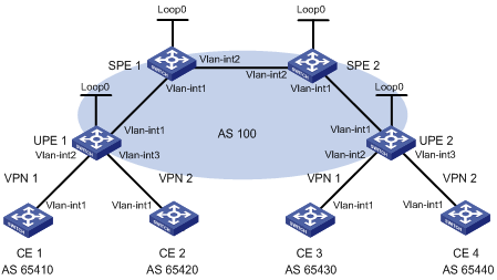
|
Interface |
IP address |
Device |
Interface |
IP address |
|
|
CE 1 |
Vlan-int1 |
10.2.1.1/24 |
CE 3 |
Vlan-int1 |
10.1.1.1/24 |
|
CE 2 |
Vlan-int1 |
10.4.1.1/24 |
CE 4 |
Vlan-int1 |
10.3.1.1/24 |
|
UPE 1 |
Loop0 |
1.1.1.9/32 |
UPE 2 |
Loop0 |
4.4.4.9/32 |
|
|
Vlan-int1 |
172.1.1.1/24 |
|
Vlan-int1 |
172.2.1.1/24 |
|
|
Vlan-int2 |
10.2.1.2/24 |
|
Vlan-int2 |
10.1.1.2/24 |
|
|
Vlan-int3 |
10.4.1.2/24 |
|
Vlan-int3 |
10.3.1.2/24 |
|
SPE 1 |
Loop0 |
2.2.2.9/32 |
SPE 2 |
Loop0 |
3.3.3.9/32 |
|
|
Vlan-int1 |
172.1.1.2/24 |
|
Vlan-int1 |
172.2.1.2/24 |
|
|
Vlan-int2 |
180.1.1.1/24 |
|
Vlan-int2 |
180.1.1.2/24 |
Configuration procedure
1. Configure UPE 1.
# Configure basic MPLS and MPLS LDP to establish LDP LSPs.
<UPE1> system-view
[UPE1] interface loopback 0
[UPE1-LoopBack0] ip address 1.1.1.9 32
[UPE1-LoopBack0] quit
[UPE1] mpls lsr-id 1.1.1.9
[UPE1] mpls
[UPE1-mpls] quit
[UPE1] mpls ldp
[UPE1-mpls-ldp] quit
[UPE1] interface vlan-interface 1
[UPE1-Vlan-interface1] ip address 172.1.1.1 24
[UPE1-Vlan-interface1] mpls
[UPE1-Vlan-interface1] mpls ldp
[UPE1-Vlan-interface1] quit
# Configure the IGP protocol, OSPF, for example.
[UPE1] ospf
[UPE1-ospf-1] area 0
[UPE1-ospf-1-area-0.0.0.0] network 172.1.1.0 0.0.0.255
[UPE1-ospf-1-area-0.0.0.0] network 1.1.1.9 0.0.0.0
[UPE1-ospf-1-area-0.0.0.0] quit
[UPE1-ospf-1] quit
# Configure VPN instances vpn1 and vpn2, allowing CE 1 and CE 2 to access UPE 1.
[UPE1] ip vpn-instance vpn1
[UPE1-vpn-instance-vpn1] route-distinguisher 100:1
[UPE1-vpn-instance-vpn1] vpn-target 100:1 both
[UPE1-vpn-instance-vpn1] quit
[UPE1] ip vpn-instance vpn2
[UPE1-vpn-instance-vpn2] route-distinguisher 100:2
[UPE1-vpn-instance-vpn2] vpn-target 100:2 both
[UPE1-vpn-instance-vpn2] quit
[UPE1] interface vlan-interface 2
[UPE1-Vlan-interface2] ip binding vpn-instance vpn1
[UPE1-Vlan-interface2] ip address 10.2.1.2 24
[UPE1-Vlan-interface2] quit
[UPE1] interface vlan-interface 3
[UPE1-Vlan-interface3] ip binding vpn-instance vpn2
[UPE1-Vlan-interface3] ip address 10.4.1.2 24
[UPE1-Vlan-interface3] quit
# Configure UPE 1 to establish an MP-IBGP peer relationship with SPE 1 and to inject VPN routes.
[UPE1] bgp 100
[UPE1-bgp] peer 2.2.2.9 as-number 100
[UPE1-bgp] peer 2.2.2.9 connect-interface loopback 0
[UPE1-bgp] ipv4-family vpnv4
[UPE1-bgp-af-vpnv4] peer 2.2.2.9 enable
[UPE1-bgp-af-vpnv4] quit
[UPE1-bgp] ipv4-family vpn-instance vpn1
[UPE1-bgp-vpn1] peer 10.2.1.1 as-number 65410
[UPE1-bgp-vpn1] import-route direct
[UPE1-bgp-vpn1] quit
[UPE1-bgp] ipv4-family vpn-instance vpn2
[UPE1-bgp-vpn1] peer 10.4.1.1 as-number 65420
[UPE1-bgp-vpn1] import-route direct
[UPE1-bgp-vpn1] quit
[UPE1-bgp] quit
2. Configure CE 1.
<CE1> system-view
[CE1] interface vlan-interface 1
[CE1-Vlan-interface1] ip address 10.2.1.1 255.255.255.0
[CE1-Vlan-interface1] quit
[CE1] bgp 65410
[CE1-bgp] peer 10.2.1.2 as-number 100
[CE1-bgp] import-route direct
[CE1] quit
3. Configure CE 2.
<CE2> system-view
[CE2] interface vlan-interface 1
[CE2-Vlan-interface1] ip address 10.4.1.1 255.255.255.0
[CE2-Vlan-interface1] quit
[CE2] bgp 65420
[CE2-bgp] peer 10.4.1.2 as-number 100
[CE2-bgp] import-route direct
[CE2] quit
4. Configure UPE 2.
# Configure basic MPLS and MPLS LDP to establish LDP LSPs.
<UPE2> system-view
[UPE2] interface loopback 0
[UPE2-Loopback0] ip address 4.4.4.9 32
[UPE2-Loopback0] quit
[UPE2] mpls lsr-id 4.4.4.9
[UPE2] mpls
[UPE2-mpls] quit
[UPE2] mpls ldp
[UPE2-mpls-ldp] quit
[UPE2] interface vlan-interface 1
[UPE2-Vlan-interface1] ip address 172.2.1.1 24
[UPE2-Vlan-interface1] mpls
[UPE2-Vlan-interface1] mpls ldp
[UPE2-Vlan-interface1] quit
# Configure the IGP protocol, OSPF, for example.
[UPE2] ospf
[UPE2-ospf-1] area 0
[UPE2-ospf-1-area-0.0.0.0] network 172.2.1.0 0.0.0.255
[UPE2-ospf-1-area-0.0.0.0] network 4.4.4.9 0.0.0.0
[UPE2-ospf-1-area-0.0.0.0] quit
[UPE2-ospf-1] quit
# Configure VPN instances vpn1 and vpn2, allowing CE 3 and CE 4 to access UPE 2.
[UPE2] ip vpn-instance vpn1
[UPE2-vpn-instance-vpn1] route-distinguisher 300:1
[UPE2-vpn-instance-vpn1] vpn-target 100:1 both
[UPE2-vpn-instance-vpn1] quit
[UPE2] ip vpn-instance vpn2
[UPE2-vpn-instance-vpn2] route-distinguisher 400:2
[UPE2-vpn-instance-vpn2] vpn-target 100:2 both
[UPE2-vpn-instance-vpn2] quit
[UPE2] interface vlan-interface 2
[UPE2-Vlan-interface2] ip binding vpn-instance vpn1
[UPE2-Vlan-interface2] ip address 10.1.1.2 24
[UPE2-Vlan-interface2] quit
[UPE2] interface vlan-interface 3
[UPE2-Vlan-interface3] ip binding vpn-instance vpn2
[UPE2-Vlan-interface3] ip address 10.3.1.2 24
[UPE2-Vlan-interface3] quit
# Configure UPE 2 to establish an MP-IBGP peer relationship with SPE 2 and to inject VPN routes.
[UPE2] bgp 100
[UPE2-bgp] peer 3.3.3.9 as-number 100
[UPE2-bgp] peer 3.3.3.9 connect-interface loopback 0
[UPE2-bgp] ipv4-family vpnv4
[UPE2-bgp-af-vpnv4] peer 3.3.3.9 enable
[UPE2-bgp-af-vpnv4] quit
[UPE2-bgp] ipv4-family vpn-instance vpn1
[UPE2-bgp-vpn1] peer 10.1.1.1 as-number 65430
[UPE2-bgp-vpn1] import-route direct
[UPE2-bgp-vpn1] quit
[UPE2-bgp] ipv4-family vpn-instance vpn2
[UPE2-bgp-vpn1] peer 10.3.1.1 as-number 65440
[UPE2-bgp-vpn1] import-route direct
[UPE2-bgp-vpn1] quit
[UPE2-bgp] quit
5. Configure CE 3.
<CE3> system-view
[CE3] interface vlan-interface 1
[CE3-Vlan-interface1] ip address 10.1.1.1 255.255.255.0
[CE3-Vlan-interface1] quit
[CE3] bgp 65430
[CE3-bgp] peer 10.1.1.2 as-number 100
[CE3-bgp] import-route direct
[CE3] quit
6. Configure CE 4.
<CE4> system-view
[CE4] interface vlan-interface 1
[CE4-Vlan-interface1] ip address 10.3.1.1 255.255.255.0
[CE4-Vlan-interface1] quit
[CE4] bgp 65440
[CE4-bgp] peer 10.3.1.2 as-number 100
[CE4-bgp] import-route direct
[CE4] quit
7. Configure SPE 1.
# Configure basic MPLS and MPLS LDP to establish LDP LSPs.
<SPE1> system-view
[SPE1] interface loopback 0
[SPE1-LoopBack0] ip address 2.2.2.9 32
[SPE1-LoopBack0] quit
[SPE1] mpls lsr-id 2.2.2.9
[SPE1] mpls
[SPE1-mpls] quit
[SPE1] mpls ldp
[SPE1-mpls-ldp] quit
[SPE1] interface vlan-interface 1
[SPE1-Vlan-interface1] ip address 172.1.1.2 24
[SPE1-Vlan-interface1] mpls
[SPE1-Vlan-interface1] mpls ldp
[SPE1-Vlan-interface1] quit
[SPE1] interface vlan-interface 2
[SPE1-Vlan-interface2] ip address 180.1.1.1 24
[SPE1-Vlan-interface2] mpls
[SPE1-Vlan-interface2] mpls ldp
[SPE1-Vlan-interface2] quit
# Configure the IGP protocol, OSPF, for example.
[SPE1] ospf
[SPE1-ospf-1] area 0
[SPE1-ospf-1-area-0.0.0.0] network 2.2.2.9 0.0.0.0
[SPE1-ospf-1-area-0.0.0.0] network 172.1.1.0 0.0.0.255
[SPE1-ospf-1-area-0.0.0.0] network 180.1.1.0 0.0.0.255
[SPE1-ospf-1-area-0.0.0.0] quit
[SPE1-ospf-1] quit
# Configure VPN instances vpn1 and vpn2.
[SPE1] ip vpn-instance vpn1
[SPE1-vpn-instance-vpn1] route-distinguisher 500:1
[SPE1-vpn-instance-vpn1 ] vpn-target 100:1 both
[SPE1-vpn-instance-vpn1] quit
[SPE1] ip vpn-instance vpn2
[SPE1-vpn-instance-vpn2] route-distinguisher 700:1
[SPE1-vpn-instance-vpn2] vpn-target 100:2 both
[SPE1-vpn-instance-vpn2] quit
# Configure SPE 1 to establish an MP-IBGP peer relationship with UPE 1 and to inject VPN routes, and specify UPE 1.
[SPE1] bgp 100
[SPE1-bgp] peer 1.1.1.9 as-number 100
[SPE1-bgp] peer 1.1.1.9 connect-interface loopback 0
[SPE1-bgp] peer 1.1.1.9 next-hop-local
[SPE1-bgp] peer 3.3.3.9 as-number 100
[SPE1-bgp] peer 3.3.3.9 connect-interface loopback 0
[SPE1-bgp] ipv4-family vpnv4
[SPE1-bgp-af-vpnv4] peer 3.3.3.9 enable
[SPE1-bgp-af-vpnv4] peer 1.1.1.9 enable
[SPE1-bgp-af-vpnv4] peer 1.1.1.9 upe
[SPE1-bgp-af-vpnv4] quit
[SPE1-bgp]ipv4-family vpn-instance vpn1
[SPE1-bgp-vpn1] quit
[SPE1-bgp]ipv4-family vpn-instance vpn2
[SPE1-bgp-vpn2] quit
[SPE1-bgp] quit
# Configure SPE 1 to advertise to UPE 1 the routes permitted by a routing policy, that is, the routes of CE 3.
[SPE1] ip ip-prefix hope index 10 permit 10.1.1.1 24
[SPE1] route-policy hope permit node 0
[SPE1-route-policy] if-match ip-prefix hope
[SPE1-route-policy] quit
[SPE1] bgp 100
[SPE1-bgp] ipv4-family vpnv4
[SPE1-bgp-af-vpnv4] peer 1.1.1.9 upe route-policy hope export
8. Configure SPE 2.
# Configure basic MPLS and MPLS LDP to establish LDP LSPs.
<SPE2> system-view
[SPE2] interface loopback 0
[SPE2-LoopBack0] ip address 3.3.3.9 32
[SPE2-LoopBack0] quit
[SPE2] mpls lsr-id 3.3.3.9
[SPE2] mpls
[SPE2-mpls] quit
[SPE2] mpls ldp
[SPE2-mpls-ldp] quit
[SPE2] interface vlan-interface 2
[SPE2-Vlan-interface2] ip address 180.1.1.2 24
[SPE2-Vlan-interface2] mpls
[SPE2-Vlan-interface2] mpls ldp
[SPE2-Vlan-interface2] quit
[SPE2] interface vlan-interface 1
[SPE2-Vlan-interface1] ip address 172.2.1.2 24
[SPE2-Vlan-interface1] mpls
[SPE2-Vlan-interface1] mpls ldp
[SPE2-Vlan-interface1] quit
# Configure the IGP protocol, OSPF, for example.
[SPE2] ospf
[SPE2-ospf-1] area 0
[SPE2-ospf-1-area-0.0.0.0] network 3.3.3.9 0.0.0.0
[SPE2-ospf-1-area-0.0.0.0] network 172.2.1.0 0.0.0.255
[SPE2-ospf-1-area-0.0.0.0] network 180.1.1.0 0.0.0.255
[SPE2-ospf-1-area-0.0.0.0] quit
[SPE2-ospf-1] quit
# Configure VPN instances vpn1 and vpn2.
[SPE2] ip vpn-instance vpn1
[SPE2-vpn-instance-vpn1] route-distinguisher 600:1
[SPE2-vpn-instance-vpn1 ] vpn-target 100:1 both
[SPE2-vpn-instance-vpn1] quit
[SPE2] ip vpn-instance vpn2
[SPE2-vpn-instance-vpn2] route-distinguisher 800:1
[SPE2-vpn-instance-vpn2] vpn-target 100:2 both
[SPE2-vpn-instance-vpn2] quit
# Configure SPE 2 to establish an MP-IBGP peer relationship with UPE 2 and to inject VPN routes, and specify UPE 2.
[SPE2] bgp 100
[SPE2-bgp] peer 4.4.4.9 as-number 100
[SPE2-bgp] peer 4.4.4.9 connect-interface loopback 0
[SPE2-bgp] peer 4.4.4.9 next-hop-local
[SPE2-bgp] peer 2.2.2.9 as-number 100
[SPE2-bgp] peer 2.2.2.9 connect-interface loopback 0
[SPE2-bgp] ipv4-family vpnv4
[SPE2-bgp-af-vpnv4] peer 2.2.2.9 enable
[SPE2-bgp-af-vpnv4] peer 4.4.4.9 enable
[SPE2-bgp-af-vpnv4] peer 4.4.4.9 upe
[SPE2-bgp-af-vpnv4] quit
[SPE2-bgp]ipv4-family vpn-instance vpn1
[SPE2-bgp-vpn1] quit
[SPE2-bgp]ipv4-family vpn-instance vpn2
[SPE2-bgp-vpn2] quit
[SPE2-bgp] quit
# Configure SPE 2 to advertise to UPE 2 the routes permitted by a routing policy, that is, the routes of CE 1.
[SPE2] ip ip-prefix hope index 10 permit 10.2.1.1 24
[SPE2] route-policy hope permit node 0
[SPE2-route-policy] if-match ip-prefix hope
[SPE2-route-policy] quit
[SPE2] bgp 100
[SPE2-bgp] ipv4-family vpnv4
[SPE2-bgp-af-vpnv4] peer 4.4.4.9 upe route-policy hope export
Configuring OSPF sham links
Network requirements
CE 1 and CE 2 belong to VPN 1 and are in the same OSPF area.
Forword VPN traffic between CE 1 and CE 2 through the MPLS backbone instead of any route in the OSPF area.
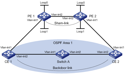
|
Interface |
IP address |
Device |
Interface |
IP address |
|
|
CE 1 |
Vlan-int1 |
100.1.1.1/24 |
CE 2 |
Vlan-int1 |
120.1.1.1/24 |
|
|
Vlan-int2 |
20.1.1.1/24 |
|
Vlan-int2 |
30.1.1.2/24 |
|
PE 1 |
Loop0 |
1.1.1.9/32 |
PE 2 |
Loop0 |
2.2.2.9/32 |
|
|
Loop1 |
3.3.3.3/32 |
|
Loop1 |
5.5.5.5/32 |
|
|
Vlan-int1 |
100.1.1.2/24 |
|
Vlan-int1 |
120.1.1.2/24 |
|
|
Vlan-int2 |
10.1.1.1/24 |
|
Vlan-int2 |
10.1.1.2/24 |
|
Switch A |
Vlan-int1 |
20.1.1.2/24 |
|
|
|
|
|
Vlan-int2 |
30.1.1.1/24 |
|
|
|
Configuration procedure
1. Configure OSPF on the customer networks.
Configure conventional OSPF on CE 1, Switch A, and CE 2 to advertise segment addresses of the interfaces as shown in Figure 30. (Details not shown)
After completing the configurations, CE 1 and CE 2 should be able to learn the OSPF route to the VLAN interface 1 of each other. The following takes CE 1 as an example:
<CE1> display ip routing-table
Routing Tables: Public
Destinations : 9 Routes : 9
Destination/Mask Proto Pre Cost NextHop Interface
20.1.1.0/24 Direct 0 0 20.1.1.1 Vlan2
20.1.1.1/32 Direct 0 0 127.0.0.1 InLoop0
20.1.1.2/32 Direct 0 0 20.1.1.2 Vlan2
30.1.1.0/24 OSPF 10 3124 20.1.1.2 Vlan2
100.1.1.0/24 Direct 0 0 100.1.1.1 Vlan1
100.1.1.1/32 Direct 0 0 127.0.0.1 InLoop0
120.1.1.0/24 OSPF 10 3125 20.1.1.2 Vlan2
127.0.0.0/8 Direct 0 0 127.0.0.1 InLoop0
127.0.0.1/32 Direct 0 0 127.0.0.1 InLoop0
2. Configure MPLS L3VPN on the backbone.
# Configure basic MPLS and MPLS LDP on PE 1 to establish LDP LSPs.
<PE1> system-view
[PE1] interface loopback 0
[PE1-LoopBack0] ip address 1.1.1.9 32
[PE1-LoopBack0] quit
[PE1] mpls lsr-id 1.1.1.9
[PE1] mpls
[PE1-mpls] quit
[PE1] mpls ldp
[PE1-mpls-ldp] quit
[PE1] interface vlan-interface 2
[PE1-Vlan-interface2] ip address 10.1.1.1 24
[PE1-Vlan-interface2] mpls
[PE1-Vlan-interface2] mpls ldp
[PE1-Vlan-interface2] quit
# Configure PE 1 to take PE 2 as the MP-IBGP peer.
[PE1] bgp 100
[PE1-bgp] peer 2.2.2.9 as-number 100
[PE1-bgp] peer 2.2.2.9 connect-interface loopback 0
[PE1-bgp] ipv4-family vpnv4
[PE1-bgp-af-vpnv4] peer 2.2.2.9 enable
[PE1-bgp-af-vpnv4] quit
[PE1-bgp] quit
# Configure OSPF on PE 1.
[PE1] ospf 1
[PE1-ospf-1] area 0
[PE1-ospf-1-area-0.0.0.0] network 1.1.1.9 0.0.0.0
[PE1-ospf-1-area-0.0.0.0] network 10.1.1.0 0.0.0.255
[PE1-ospf-1-area-0.0.0.0] quit
[PE1-ospf-1] quit
# Configure basic MPLS and MPLS LDP on PE 2 to establish LDP LSPs.
<PE2> system-view
[PE2] interface loopback 0
[PE2-LoopBack0] ip address 2.2.2.9 32
[PE2-LoopBack0] quit
[PE2] mpls lsr-id 2.2.2.9
[PE2] mpls
[PE2-mpls] quit
[PE2] mpls ldp
[PE2-mpls-ldp] quit
[PE2] interface vlan-interface 2
[PE2-Vlan-interface2] ip address 10.1.1.2 24
[PE2-Vlan-interface2] mpls
[PE2-Vlan-interface2] mpls ldp
[PE2-Vlan-interface2] quit
# Configure PE 2 to take PE 1 as the MP-IBGP peer.
[PE2] bgp 100
[PE2-bgp] peer 1.1.1.9 as-number 100
[PE2-bgp] peer 1.1.1.9 connect-interface loopback 0
[PE2-bgp] ipv4-family vpnv4
[PE2-bgp-af-vpnv4] peer 1.1.1.9 enable
[PE2-bgp-af-vpnv4] quit
[PE2-bgp] quit
# Configure OSPF on PE 2.
[PE2]ospf 1
[PE2-ospf-1]area 0
[PE2-ospf-1-area-0.0.0.0]network 2.2.2.9 0.0.0.0
[PE2-ospf-1-area-0.0.0.0]network 10.1.1.0 0.0.0.255
[PE2-ospf-1-area-0.0.0.0]quit
[PE2-ospf-1]quit
3. Configure PEs to allow CEs to access the network.
# Configure PE 1 to allow CE 1 to access the network.
[PE1] ip vpn-instance vpn1
[PE1-vpn-instance-vpn1] route-distinguisher 100:1
[PE1-vpn-instance-vpn1] vpn-target 1:1
[PE1-vpn-instance-vpn1] quit
[PE1] interface vlan-interface 1
[PE1-Vlan-interface1] ip binding vpn-instance vpn1
[PE1-Vlan-interface1] ip address 100.1.1.2 24
[PE1-Vlan-interface1] quit
[PE1] ospf 100 vpn-instance vpn1
[PE1-ospf-100] domain-id 10
[PE1-ospf-100] area 1
[PE1-ospf-100-area-0.0.0.1] network 100.1.1.0 0.0.0.255
[PE1-ospf-100-area-0.0.0.1] quit
[PE1-ospf-100] quit
[PE2] bgp 100
[PE1-bgp] ipv4-family vpn-instance vpn1
[PE1-bgp-vpn1] import-route ospf 100
[PE1-bgp-vpn1] import-route direct
[PE1-bgp-vpn1] quit
[PE1-bgp] quit
# Configure PE 2 to allow CE 2 to access the network.
[PE2] ip vpn-instance vpn1
[PE2-vpn-instance-vpn1] route-distinguisher 100:2
[PE2-vpn-instance-vpn1] vpn-target 1:1
[PE2-vpn-instance-vpn1] quit
[PE2] interface vlan-interface 1
[PE2-Vlan-interface1] ip binding vpn-instance vpn1
[PE2-Vlan-interface1] ip address 120.1.1.2 24
[PE2-Vlan-interface1] quit
[PE2] ospf 100 vpn-instance vpn1
[PE2-ospf-100] domain-id 10
[PE2-ospf-100] area 1
[PE2-ospf-100-area-0.0.0.1] network 120.1.1.0 0.0.0.255
[PE2-ospf-100-area-0.0.0.1] quit
[PE2-ospf-100] quit
[PE2] bgp 100
[PE2-bgp] ipv4-family vpn-instance vpn1
[PE2-bgp-vpn1] import-route ospf 100
[PE2-bgp-vpn1] import-route direct
[PE2-bgp-vpn1] quit
[PE2-bgp] quit
After completing the previous configurations, if you issue the display ip routing-table vpn-instance command on the PEs, you can see that the path to the peer CE is along the OSPF route across the customer networks, instead of the BGP route across the backbone. Take PE 1 as an example:
[PE1] display ip routing-table vpn-instance vpn1
Routing Tables: vpn1
Destinations : 5 Routes : 5
Destination/Mask Proto Pre Cost NextHop Interface
20.1.1.0/24 OSPF 10 1563 100.1.1.1 Vlan1
30.1.1.0/24 OSPF 10 3125 100.1.1.1 Vlan1
100.1.1.0/24 Direct 0 0 100.1.1.2 Vlan1
100.1.1.2/32 Direct 0 0 127.0.0.1 InLoop0
120.1.1.0/24 OSPF 10 3126 100.1.1.1 Vlan1
4. Configure a sham link.
# Configure PE 1.
[PE1] interface loopback 1
[PE1-LoopBack1] ip binding vpn-instance vpn1
[PE1-LoopBack1] ip address 3.3.3.3 32
[PE1-LoopBack1] quit
[PE1] ospf 100
[PE1-ospf-100] area 1
[PE1-ospf-100-area-0.0.0.1] sham-link 3.3.3.3 5.5.5.5 cost 10
[PE1-ospf-100-area-0.0.0.1] quit
[PE1-ospf-100] quit
# Configure PE 2.
[PE2] interface loopback 1
[PE2-LoopBack1] ip binding vpn-instance vpn1
[PE2-LoopBack1] ip address 5.5.5.5 32
[PE2-LoopBack1] quit
[PE2] ospf 100
[PE2-ospf-100] area 1
[PE2-ospf-100-area-0.0.0.1] sham-link 5.5.5.5 3.3.3.3 cost 10
[PE2-ospf-100-area-0.0.0.1] quit
[PE2-ospf-100] quit
After completing the previous configurations, if you issue the display ip routing-table vpn-instance command again on the PEs, you can see that the path to the peer CE is now along the BGP route across the backbone, and that a route to the sham link destination address is present. Take PE 1 as an example:
[PE1] display ip routing-table vpn-instance vpn1
Routing Tables: vpn1
Destinations : 6 Routes : 6
Destination/Mask Proto Pre Cost NextHop Interface
3.3.3.3/32 Direct 0 0 127.0.0.1 InLoop0
5.5.5.5/32 BGP 255 0 2.2.2.9 NULL0
20.1.1.0/24 OSPF 10 1563 100.1.1.1 Vlan1
100.1.1.0/24 Direct 0 0 100.1.1.2 Vlan1
100.1.1.2/32 Direct 0 0 127.0.0.1 InLoop0
120.1.1.0/24 BGP 255 0 2.2.2.9 NULL0
Issuing the display ip routing-table command on the CEs, you can see that the cost of the OSPF route to the peer CE is now 10 (the cost configured for the sham link), and that the next hop is now the VLAN interface 1 connected to the PE. This means that VPN traffic to the peer will be forwarded over the backbone. Take CE 1 as an example:
[CE1] display ip routing-table
Routing Tables: Public
Destinations : 9 Routes : 9
Destination/Mask Proto Pre Cost NextHop Interface
20.1.1.0/24 Direct 0 0 20.1.1.1 Vlan2
20.1.1.1/32 Direct 0 0 127.0.0.1 InLoop0
20.1.1.2/32 Direct 0 0 20.1.1.2 Vlan2
30.1.1.0/24 OSPF 10 1574 100.1.1.2 Vlan1
100.1.1.0/24 Direct 0 0 100.1.1.1 Vlan1
100.1.1.1/32 Direct 0 0 127.0.0.1 InLoop0
120.1.1.0/24 OSPF 10 12 100.1.1.2 Vlan1
127.0.0.0/8 Direct 0 0 127.0.0.1 InLoop0
127.0.0.1/32 Direct 0 0 127.0.0.1 InLoop0
Issuing the display ospf sham-link command on the PEs, you can see the established sham link. Take PE 1 as an example:
[PE1] display ospf sham-link
OSPF Process 100 with Router ID 100.1.1.2
Sham Link:
Area RouterId Source-IP Destination-IP State Cost
0.0.0.1 100.1.1.2 3.3.3.3 5.5.5.5 P-2-P 10
Issuing the display ospf sham-link area command, you can see that the status of the peer is Full:
[PE1] display ospf sham-link area 1
OSPF Process 100 with Router ID 100.1.1.2
Sham-Link: 3.3.3.3 --> 5.5.5.5
Neighbour State: Full
Area: 0.0.0.1
Cost: 10 State: P-2-P, Type: Sham
Timers: Hello 10 , Dead 40 , Retransmit 5 , Transmit Delay 1
Configuring BGP AS number substitution
Network requirements
As shown in Figure 31, CE 1 and CE 2 belong to VPN 1 and are connected to PE 1 and PE 2 respectively. In addition, they use the same AS number 600.
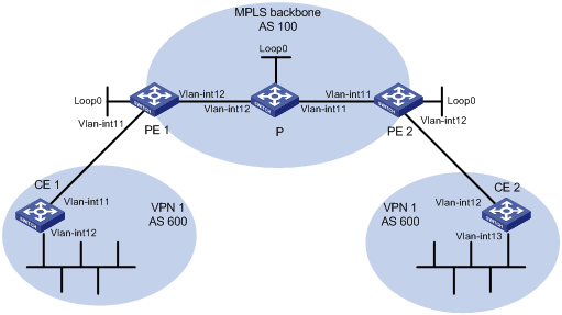
|
Interface |
IP address |
Device |
Interface |
IP address |
|
|
CE 1 |
Vlan-int1 |
10.1.1.1/24 |
P |
Loop0 |
2.2.2.9/32 |
|
|
Vlan-int2 |
100.1.1.1/24 |
|
Vlan-int1 |
30.1.1.1/24 |
|
PE 1 |
Loop0 |
1.1.1.9/32 |
|
Vlan-int2 |
20.1.1.2/24 |
|
|
Vlan-int1 |
10.1.1.2/24 |
PE 2 |
Loop0 |
3.3.3.9/32 |
|
|
Vlan-int2 |
20.1.1.1/24 |
|
Vlan-int1 |
30.1.1.2/24 |
|
CE 2 |
Vlan-int1 |
10.2.1.1/24 |
|
Vlan-int2 |
10.2.1.2/24 |
|
|
Vlan-int2 |
200.1.1.1/24 |
|
|
|
Configuration procedure
1. Configuring basic MPLS L3VPN.
? Configure OSPF on the MPLS backbone to allow the PEs and P switch to learn the routes of the loopback interfaces from each other.
? Configure basic MPLS and MPLS LDP on the MPLS backbone to establish LDP LSPs.
? Establish an MP-IBGP peer relationship between the PEs to advertise VPN IPv4 routes.
? Configure the VPN instance of VPN 1 on PE 2 to allow CE 2 to access the network.
? Configure the VPN instance of VPN 1 on PE 1 to allow CE 1 to access the network.
? Configure BGP between PE 1 and CE 1, and between PE 2 and CE 2 to inject routes of CEs into PEs.
After completing the previous configurations, if you issue the display ip routing-table command on CE 2, you can see that CE 2 has learned the route to network segment 10.1.1.0/24, where the interface used by CE 1 to access PE 1 resides; but has not learned the route to the VPN (100.1.1.0/24) behind CE 1. You can see the similar situation on CE 1.
<CE2> display ip routing-table
Routing Tables: Public
Destinations : 8 Routes : 8
Destination/Mask Proto Pre Cost NextHop Interface
10.1.1.0/24 BGP 255 0 10.2.1.2 Vlan1
10.1.1.1/32 BGP 255 0 10.2.1.2 Vlan1
10.2.1.0/24 Direct 0 0 10.2.1.1 Vlan1
10.2.1.1/32 Direct 0 0 127.0.0.1 InLoop0
10.2.1.2/32 Direct 0 0 10.2.1.2 Vlan1
127.0.0.0/8 Direct 0 0 127.0.0.1 InLoop0
127.0.0.1/32 Direct 0 0 127.0.0.1 InLoop0
200.1.1.0/24 Direct 0 0 200.1.1.1 InLoop0
200.1.1.1/32 Direct 0 0 127.0.0.1 InLoop0
Issuing the display ip routing-table vpn-instance command on the PEs, you can see the route to the VPN behind the peer CE. Take PE 2 as an example:
<PE2> display ip routing-table vpn-instance vpn1
Routing Tables: vpn1
Destinations : 7 Routes : 7
Destination/Mask Proto Pre Cost NextHop Interface
10.1.1.0/24 BGP 255 0 1.1.1.9 NULL0
10.1.1.1/32 BGP 255 0 1.1.1.9 NULL0
10.2.1.0/24 Direct 0 0 10.2.1.2 Vlan1
10.2.1.1/32 Direct 0 0 10.2.1.1 Vlan1
10.2.1.2/32 Direct 0 0 127.0.0.1 InLoop0
100.1.1.1/32 BGP 255 0 1.1.1.9 NULL0
200.1.1.1/32 BGP 255 0 10.2.1.1 Vlan1
Issuing the display bgp routing-table peer received-routes command on CE 2, you can see that CE 2 did not receive the route to 100.1.1.1/32.
<CE2> display bgp routing-table peer 10.2.1.2 received-routes
Total Number of Routes: 4
BGP Local router ID is 10.2.1.1
Status codes: * - valid, ^ - VPN best, > - best, d - damped,
h - history, i - internal, s - suppressed, S - Stale
Origin : i - IGP, e - EGP, ? - incomplete
Network NextHop MED LocPrf PrefVal Path/Ogn
*> 10.1.1.0/24 10.2.1.2 0 0 100?
*> 10.1.1.1/32 10.2.1.2 0 0 100?
* 10.2.1.0/24 10.2.1.2 0 0 100?
* 10.2.1.1/32 10.2.1.2 0 0 100?
2. Configure BGP AS number substitution.
# Configure BGP AS number substitution on PE 2.
<PE2> system-view
[PE2] bgp 100
[PE2-bgp] ipv4-family vpn-instance vpn1
[PE2-bgp-vpn1] peer 10.2.1.1 substitute-as
[PE2-bgp-vpn1] quit
[PE2-bgp] quit
You can see that among the routes advertised by PE 2 to CE 2, the AS_PATH of 100.1.1.1/32 has changed from 100 600 to 100 100:
*0.13498737 PE2 RM/7/RMDEBUG:
BGP.vpn1: Send UPDATE to 10.2.1.1 for following destinations :
Origin : Incomplete
AS Path : 100 100
Next Hop : 10.2.1.2
100.1.1.1/32
Display again the routing information that CE 2 receives and the routing table:
<CE2> display bgp routing-table peer 10.2.1.2 received-routes
Total Number of Routes: 5
BGP Local router ID is 10.2.1.1
Status codes: * - valid, ^ - VPN best, > - best, d - damped,
h - history, i - internal, s - suppressed, S - Stale
Origin : i - IGP, e - EGP, ? - incomplete
Network NextHop MED LocPrf PrefVal Path/Ogn
*> 10.1.1.0/24 10.2.1.2 0 100?
*> 10.1.1.1/32 10.2.1.2 0 100?
* 10.2.1.0/24 10.2.1.2 0 0 100?
* 10.2.1.1/32 10.2.1.2 0 0 100?
*> 100.1.1.1/32 10.2.1.2 0 100 100?
<CE2> display ip routing-table
Routing Tables: Public
Destinations : 9 Routes : 9
Destination/Mask Proto Pre Cost NextHop Interface
10.1.1.0/24 BGP 255 0 10.2.1.2 Vlan1
10.1.1.1/32 BGP 255 0 10.2.1.2 Vlan1
10.2.1.0/24 Direct 0 0 10.2.1.1 Vlan1
10.2.1.1/32 Direct 0 0 127.0.0.1 InLoop0
10.2.1.2/32 Direct 0 0 10.2.1.2 Vlan1
100.1.1.1/32 BGP 255 0 10.2.1.2 Vlan1
127.0.0.0/8 Direct 0 0 127.0.0.1 InLoop0
127.0.0.1/32 Direct 0 0 127.0.0.1 InLoop0
200.1.1.1/32 Direct 0 0 127.0.0.1 InLoop0
After configuring BGP AS substitution on PE 1 too, the VLAN interfaces of CE 1 and CE 2 should be able to ping each other:
<CE1> ping –a 100.1.1.1 200.1.1.1
PING 200.1.1.1: 56 data bytes, press CTRL_C to break
Reply from 200.1.1.1: bytes=56 Sequence=1 ttl=253 time=109 ms
Reply from 200.1.1.1: bytes=56 Sequence=2 ttl=253 time=67 ms
Reply from 200.1.1.1: bytes=56 Sequence=3 ttl=253 time=66 ms
Reply from 200.1.1.1: bytes=56 Sequence=4 ttl=253 time=85 ms
Reply from 200.1.1.1: bytes=56 Sequence=5 ttl=253 time=70 ms
--- 200.1.1.1 ping statistics ---
5 packet(s) transmitted
5 packet(s) received
0.00% packet loss
round-trip min/avg/max = 66/79/109 ms
Configuring multi-role host
Network requirements
CE 1 and CE 3 belong to VPN 1. CE 2 belongs to VPN 2. PC 2 is connected to CE 2.
Configure the multi-role host feature, so that PC 2 can access both VPN 1 and VPN 2.
Figure 32 Network diagram
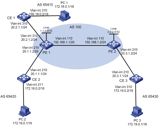
Configuration procedure
1. Configure OSPF on the MPLS backbone.
# Configure OSPF on PE 1.
[PE1] interface loopback 0
[PE1-LoopBack0] ip address 1.1.1.9 32
[PE1-LoopBack0] quit
[PE1] vlan 110
[PE1-vlan110] interface vlan-interface 110
[PE1-Vlan-interface110] ip address 192.168.1.1 24
[PE1-Vlan-interface110] quit
[PE1] ospf
[PE1-ospf-1] area 0
[PE1-ospf-1-area-0.0.0.0] network 192.168.1.0 0.0.0.255
[PE1-ospf-1-area-0.0.0.0] network 1.1.1.9 0.0.0.0
[PE1-ospf-1-area-0.0.0.0] quit
[PE1-ospf-1] quit
# Configure OSPF on PE 2.
[PE2] interface loopback 0
[PE2-LoopBack0] ip address 2.2.2.9 32
[PE2-LoopBack0] quit
[PE2] vlan 110
[PE2-vlan110] interface vlan-interface 110
[PE1-Vlan-interface110] ip address 192.168.1.2 24
[PE2-Vlan-interface110] quit
[PE2] ospf
[PE2-ospf-1] area 0
[PE2-ospf-1-area-0.0.0.0] network 192.168.1.0 0.0.0.255
[PE2-ospf-1-area-0.0.0.0] network 2.2.2.9 0.0.0.0
[PE2-ospf-1-area-0.0.0.0] quit
[PE2-ospf-1] quit
2. Configure the basic MPLS settings and create VPN instances.
# Configure basic MPLS on PE1.
[PE1] mpls lsr-id 1.1.1.9
[PE1] mpls
[PE1-mpls] lsp-trigger all
[PE1-mpls] quit
[PE1] mpls ldp
[PE1-mpls-ldp] quit
[PE1] vlan 110
[PE1-vlan110]interface vlan-interface 110
[PE1-Vlan-interface110] mpls
[PE1-Vlan-interface110] mpls ldp
[PE1-Vlan-interface110] quit
# Create VPN instances for VPN 1 and VPN 2 on PE 1, bind VLAN-interface 310 to VPN 1 and VLAN-interface 210 to VPN 2.
[PE1] ip vpn-instance vpn1
[PE1-vpn-vpn1] route-distinguisher 100:1
[PE1-vpn-vpn1] vpn-target 100:1 both
[PE1-vpn-vpn1] quit
[PE1] ip vpn-instance vpn2
[PE1-vpn-vpn2] route-distinguisher 100:2
[PE1-vpn-vpn2] vpn-target 100:2 both
[PE1-vpn-vpn2] quit
[PE1] vlan 310
[PE1-vlan310] interface vlan-interface 310
[PE1-Vlan-interface310] ip binding vpn-instance vpn1
[PE1-Vlan-interface310] ip address 20.2.1.2 24
[PE1-Vlan-interface310] quit
[PE1] vlan 210
[PE1-vlan210] interface vlan-interface 210
[PE1-Vlan-interface210] ip binding vpn-instance vpn2
[PE1-Vlan-interface210] ip address 20.1.1.2 24
[PE1-Vlan-interface210] quit
# Configure basic MPLS on PE2.
[PE2] mpls lsr-id 2.2.2.9
[PE2] mpls
[PE2-mpls] lsp-trigger all
[PE2-mpls] quit
[PE2] mpls ldp
[PE2-mpls-ldp] quit
[PE2] vlan 110
[PE2-vlan110] interface vlan-interface 110
[PE2-Vlan-interface110] mpls
[PE2-Vlan-interface110] mpls ldp
[PE2-Vlan-interface110] quit
# Create a VPN instance for VPN 1 on PE 2 and bind VLAN-interface 210 to the VPN instance.
[PE2] ip vpn-instance vpn1
[PE2-vpn-vpn1] route-distinguisher 300:1
[PE2-vpn-vpn1] vpn-target 100:1 both
[PE2-vpn-vpn1] quit
[PE2] vlan 210
[PE2-vlan210] interface vlan-interface 210
[PE2-Vlan-interface210] ip binding vpn-instance vpn1
[PE2-Vlan-interface210] ip address 20.3.1.2 24
[PE2-Vlan-interface210] quit
3. Configure BGP.
# Configure CE 1.
[CE1] vlan 310
[CE1-vlan310] interface vlan-interface 310
[CE1-Vlan-interface310] ip address 20.2.1.1 24
[CE1-Vlan-interface310] quit
[CE1] bgp 65410
[CE1-bgp] import-route direct
[CE1-bgp] group 10 external
[CE1-bgp] peer 20.2.1.2 group 10 as-number 100
[CE1-bgp] quit
# Configure CE 2.
[CE2] vlan 210
[CE2-vlan210] interface vlan-interface 210
[CE2-Vlan-interface210] ip address 20.1.1.1 24
[CE2-Vlan-interface210] quit
# Configure CE 3.
[CE3] vlan 210
[CE3-vlan210] interface vlan-interface 210
[CE3-Vlan-interface210] ip address 20.3.1.1 24
[CE3-Vlan-interface210] quit
[CE3] bgp 65430
[CE3-bgp] import-route direct
[CE3-bgp] group 10 external
[CE3-bgp] peer 20.3.1.2 group 10 as-number 100
[CE3-bgp] quit
# Configure PE 1:
? Establish an IBGP peer relationship with PE 2 in BGP-VPNv4 subaddress family view.
? Establish an EBGP peer relation with CE 1 in BGP VPN 1 instance view.
? Redistribute the static routes and advertise the routes to the remote PE in VPN 2 instance view. (Static routes are used for communication between PE 1 and CE 2.)
[PE1] bgp 100
[PE1-bgp] group 10
[PE1-bgp] peer 2.2.2.9 group 10
[PE1-bgp] peer 2.2.2.9 connect-interface loopback 0
[PE1-bgp] ipv4-family vpnv4
[PE1-bgp-af-vpn] peer 10 enable
[PE1-bgp-af-vpn] peer 2.2.2.9 group 10
[PE1-bgp-af-vpn] quit
[PE1-bgp] ipv4-family vpn-instance vpn1
[PE1-bgp-af-vpn-instance] import-route direct
[PE1-bgp-af-vpn-instance] group 20 external
[PE1-bgp-af-vpn-instance] peer 20.2.1.1 group 20 as-number 65410
[PE1-bgp-af-vpn-instance] quit
[PE1-bgp] ipv4-family vpn-instance vpn2
[PE1-bgp-af-vpn-instance] import-route direct
[PE1-bgp-af-vpn-instance] import-route static
# Configure PE 2:
? Establish an IBGP peer relationship with PE 1 in BGP-VPNv4 subaddress family view.
? Establish an EBGP peer relationship with CE 3 in BGP VPN instance view.
[PE2] bgp 100
[PE2-bgp] group 10
[PE2-bgp] peer 1.1.1.9 group 10
[PE2-bgp] peer 1.1.1.9 connect-interface loopback 0
[PE2-bgp] ipv4-family vpnv4
[PE2-bgp-af-vpn] peer 10 enable
[PE2-bgp-af-vpn] peer 1.1.1.9 group 10
[PE2-bgp-af-vpn] quit
[PE2-bgp] ipv4-family vpn-instance vpn1
[PE2-bgp-af-vpn-instance] import-route direct
[PE2-bgp-af-vpn-instance] group 20 external
[PE2-bgp-af-vpn-instance] peer 20.3.1.1 group 20 as-number 65430
[PE2-bgp-af-vpn-instance] quit
[PE2-bgp] quit
4. Configure the multi-role host feature.
You can configure a static route between CE 2 and PE 1 or use a routing protocol. To use a routing protocol between CE 2 and PE 1, configure PE 1 to not advertise any routes to CE 2 to avoid routing loop.
The following example shows how to use static routes to configure the multi-role host feature:
# On CE 2, create a default route to PE 1.
[CE2] ip route-static 0.0.0.0 0.0.0.0 20.1.1.2
# Create a multi-role host route on PE 1.
[PE1] ip route-static vpn-instance vpn1 172.16.0.0 16 vpn-instance vpn2 20.1.1.1
# Redistribute routes of VPN 1 to VPN 2 through the RT attribute.
[PE1] ip vpn-instance vpn2
[PE1-vpn-vpn2] vpn-target 100:1 import-extcommunity
Configuring BGP AS number substitution and SoO
Network requirements
CE 1, CE 2, and CE 3 belong to VPN 1 and connect to PE1, PE 2, and PE 3 respectively. CE 1 and CE 2 reside in the same site. CE1, CE2, and CE 3 all use AS number 600.
To avoid route loss, configure BGP AS number substitution on PEs. To avoid routing loops, configure a routing policy on PE1 and PE2 respectively to add the SoO attribute to routes received from CE 1 and CE 2.
Figure 33 Network diagram
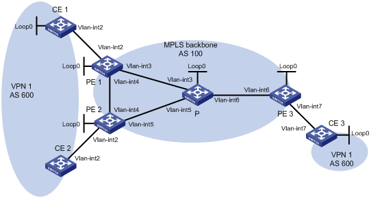
|
Device |
Interface |
IP address |
Device |
Interface |
IP address |
|
CE 1 |
Loop0 |
100.1.1.1/32 |
CE 3 |
Loop0 |
200.1.1.1/32 |
|
|
Vlan-int2 |
10.1.1.1/24 |
|
Vlan-int7 |
10.3.1.1/24 |
|
CE 2 |
Vlan-int2 |
10.2.1.1/24 |
PE 2 |
Loop0 |
2.2.2.9/32 |
|
PE 1 |
Loop0 |
1.1.1.9/32 |
|
Vlan-int2 |
10.2.1.2/24 |
|
|
Vlan-int2 |
10.1.1.2/24 |
|
Vlan-int4 |
20.1.1.2/24 |
|
|
Vlan-int3 |
30.1.1.1/24 |
|
Vlan-int5 |
40.1.1.1/24 |
|
|
Vlan-int4 |
20.1.1.1/24 |
P |
Loop0 |
3.3.3.9/32 |
|
PE 3 |
Loop0 |
4.4.4.9/32 |
|
Vlan-int3 |
30.1.1.2/24 |
|
|
Vlan-int6 |
50.1.1.2/24 |
|
Vlan-int5 |
40.1.1.2/24 |
|
|
Vlan-int7 |
10.3.1.2/24 |
|
Vlan-int6 |
50.1.1.1/24 |
Configuration procedure
1. Configure basic MPLS L3VPN. (Details not shown)
? Configure OSPF on the MPLS backbone to allow the PEs and P device to learn the routes of the loopback interfaces from each other.
? Configure basic MPLS and MPLS LDP on the MPLS backbone to establish LDP LSPs.
? Establish MP-IBGP peer relationships between the PEs to advertise VPN IPv4 routes.
? Configure VPN 1 on PE 1 to allow CE 1 to access the network.
? Configure VPN 1 on PE 2 to allow CE 2 to access the network.
? Configure VPN 1 on PE 3 to allow CE 3 to access the network.
? Configure BGP between PE 1 and CE 1, between PE 2 and CE 2, and between PE 3 and CE 3 to inject routes of CEs into PEs.
2. Configure BGP AS number substitution.
# Configure BGP AS number substitution on PE 1, PE2, and PE3 as described in “Configuring BGP AS number substitution.”
# Display the routing table on CE 2. You can see that CE 2 has learned the route 100.1.1.1/32 to CE 1. A routing loop has occurred because CE1 and CE 2 reside in the same site.
<CE2> display bgp routing-table peer 10.2.1.2 received-routes
Total Number of Routes: 8
BGP Local router ID is 10.2.1.1
Status codes: * - valid, ^ - VPN best, > - best, d - damped,
h - history, i - internal, s - suppressed, S - Stale
Origin : i - IGP, e - EGP, ? - incomplete
Network NextHop MED LocPrf PrefVal Path/Ogn
*> 10.1.1.0/24 10.2.1.2 0 100?
*> 10.1.1.1/32 10.2.1.2 0 100?
* 10.2.1.0/24 10.2.1.2 0 0 100?
* 10.2.1.1/32 10.2.1.2 0 0 100?
* 10.3.1.0/24 10.2.1.2 0 100?
* 10.3.1.1/32 10.2.1.2 0 100?
*> 100.1.1.1/32 10.2.1.2 0 100 100?
*> 200.1.1.1/32 10.2.1.2 0 100 100?
<CE2> display ip routing-table
Routing Tables: Public
Destinations : 10 Routes : 10
Destination/Mask Proto Pre Cost NextHop Interface
10.1.1.0/24 BGP 255 0 10.2.1.2 Vlan2
10.1.1.1/32 BGP 255 0 10.2.1.2 Vlan2
10.2.1.0/24 Direct 0 0 10.2.1.1 Vlan2
10.2.1.1/32 Direct 0 0 127.0.0.1 InLoop0
10.3.1.0/24 BGP 255 0 10.2.1.2 Vlan2
10.3.1.1/32 BGP 255 0 10.2.1.2 Vlan2
100.1.1.1/32 BGP 255 0 10.2.1.2 Vlan2
127.0.0.0/8 Direct 0 0 127.0.0.1 InLoop0
127.0.0.1/32 Direct 0 0 127.0.0.1 InLoop0
200.1.1.1/32 BGP 255 0 10.2.1.2 Vlan2
3. Configure the SoO attribute.
# On PE 1, configure a routing policy named soo to add the specified SoO attribute.
<PE1> system-view
[PE1] route-policy soo permit node 10
[PE1-route-policy] apply extcommunity soo 1:100 additive
[PE1-route-policy] quit
# On PE 1, apply the routing policy soo to routes received from CE 1.
[PE1] bgp 100
[PE1-bgp] ipv4-family vpn-instance vpn1
[PE1-bgp-vpn1] peer 10.1.1.1 route-policy soo import
[PE1-bgp-vpn1] quit
[PE1-bgp] quit
# On PE 2, configure a routing policy named soo to add the specified SoO attribute.
<PE2> system-view
[PE2] route-policy soo permit node 10
[PE2-route-policy] apply extcommunity soo 1:100 additive
[PE2-route-policy] quit
# On PE 2, apply the routing policy soo to routes received from CE 2.
[PE2] bgp 100
[PE2-bgp] ipv4-family vpn-instance vpn1
[PE2-bgp-vpn1] peer 10.2.1.1 route-policy soo import
[PE2-bgp-vpn1] quit
[PE2-bgp] quit
# PE 2 will not advertise routes received from CE 1 to CE 2 because the same SoO attribute has been configured. Display the routing table of CE 2. You can see that the route 100.1.1.1/32 has been removed.
<CE2> display ip routing-table
Routing Tables: Public
Destinations : 9 Routes : 9
Destination/Mask Proto Pre Cost NextHop Interface
10.1.1.0/24 BGP 255 0 10.2.1.2 Vlan2
10.1.1.1/32 BGP 255 0 10.2.1.2 Vlan2
10.2.1.0/24 Direct 0 0 10.2.1.1 Vlan2
10.2.1.1/32 Direct 0 0 127.0.0.1 InLoop0
10.3.1.0/24 BGP 255 0 10.2.1.2 Vlan2
10.3.1.1/32 BGP 255 0 10.2.1.2 Vlan2
127.0.0.0/8 Direct 0 0 127.0.0.1 InLoop0
127.0.0.1/32 Direct 0 0 127.0.0.1 InLoop0
200.1.1.1/32 BGP 255 0 10.2.1.2 Vlan2
IPv6 MPLS L3VPN overview
MPLS L3VPN applies to the IPv4 environment. It uses BGP to advertise IPv4 VPN routes and uses MPLS to forward IPv4 VPN packets on the service provider backbone.
IPv6 MPLS L3VPN functions similarly. It uses BGP to advertise IPv6 VPN routes and uses MPLS to forward IPv6 VPN packets on the service provider backbone.
Figure 34 shows the typical IPv6 MPLS L3VPN model. At present, the service provider backbone in the IPv6 MPLS L3VPN model is an IPv4 network. IPv6 runs inside the VPNs and between CEs and PEs. Therefore, PEs must support both IPv4 and IPv6. The PE-CE interfaces of a PE run IPv6 and the PE-P interface of a PE runs IPv4.
Figure 34 Network diagram for the IPv6 MPLS L3VPN model
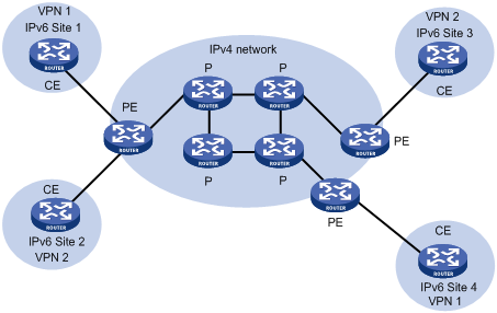
IPv6 MPLS L3VPN packet forwarding
Figure 35 IPv6 MPLS L3VPN packet forwarding diagram
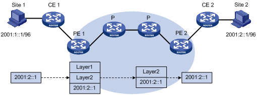
As shown in Figure 35, the IPv6 MPLS L3VPN packet forwarding procedure is as follows:
1. The PC at Site 1 sends an IPv6 packet destined for 2001:2::1, the PC at Site 2. CE 1 transmits the packet to PE 1.
2. Based on the inbound interface and destination address of the packet, PE 1 searches the routing table of the VPN instance. Finding a matching entry, PE 1 labels the packet with both inner and outer labels and forwards the packet out.
3. The MPLS backbone transmits the packet to PE 2 by outer label. The outer label is removed from the packet at the penultimate hop.
4. According to the inner label and destination address of the packet, PE 2 searches the routing table of the VPN instance to determine the outbound interface and then forwards the packet out the interface to CE 2.
5. CE 2 forwards the packet to the destination by IPv6 forwarding.
IPv6 MPLS L3VPN routing information advertisement
The IPv6 VPN routing information of a local CE is advertised to a remote peer PE in three steps:
1. From the local CE to the ingress PE.
2. From the ingress PE to the egress PE.
3. From the egress PE to the remote peer CE.
Then, a route is available from the local CE to the remote CE.
Routing information exchange from the local CE to the ingress PE
After establishing an adjacency with the directly connected PE, a CE advertises its IPv6 VPN routes to the PE.
The routes between a CE and a PE can be IPv6 static routes, RIPng routes, OSPFv3 routes, IPv6 IS-IS routes, or EBGP routes. No matter which routing protocol is used, the CE always advertises standard IPv6 routes to the PE.
Routing information exchange from the ingress PE to the egress PE
After learning the IPv6 VPN routes from the CE, the ingress PE adds RDs and VPN targets for these standard IPv6 routes to create VPN-IPv6 routes, saves them to the routing table of the VPN instance created for the CE, and then triggers MPLS to assign VPN labels for them.
Then, the ingress PE advertises the VPN-IPv6 routes to the egress PE through MP-BGP.
Finally, the egress PE compares the export target attributes of the VPN-IPv6 routes with the import target attributes that it maintains for the VPN instance and, if they are the same, adds the routes to the routing table of the VPN instance.
The PEs use an IGP to ensure the connectivity between them.
Routing information exchange from the egress PE to the remote CE
The exchange of routing information between the egress PE and the remote CE is the same as that between the local CE and the ingress PE.
IPv6 MPLS L3VPN networking schemes and functions
At present, IPv6 MPLS L3VPN supports the following networking schemes and functions:
· Basic VPN networking
· Inter-AS VPN option A
· Inter-AS VPN option C
· Carrier’s carrier
· Multi-VPN-instance CE
IPv6 MPLS L3VPN configuration task list
Complete the following tasks to configure IPv6 MPLS L3VPN:
|
Task |
Remarks |
|
By configuring basic IPv6 MPLS L3VPN, you can construct simple IPv6 VPN networks over an MPLS backbone. To deploy special IPv6 MPLS L3VPN networks, such as inter-AS VPN, you also need to perform some specific configurations in addition to the basic IPv6 MPLS L3VPN configuration. For more information, see the related sections. |
|
Configuring basic IPv6 MPLS L3VPN
Basic IPv6 MPLS L3VPN configuration task list
The key task in IPv6 MPLS L3VPN configuration is to manage the advertisement of IPv6 VPN routes on the MPLS backbone, including PE-CE route exchange and PE-PE route exchange.
Complete the following tasks to configure basic IPv6 MPLS L3VPN:
|
Task |
Remarks |
|
|
Required |
||
|
Required |
||
|
Optional |
||
|
Optional |
||
|
Optional |
||
|
Required |
||
|
Required |
||
|
Configuring routing features for the BGP-VPNv6 subaddress family |
Optional |
|
Configuration prerequisites
Before configuring basic IPv6 MPLS L3VPN, complete the following tasks:
· Configure an IGP on the PEs and Ps to ensure IP connectivity within the MPLS backbone.
· Configure basic MPLS for the MPLS backbone
· Configure MPLS LDP on PEs and Ps to establish LDP LSPs
Configuring VPN instances
By configuring VPN instances on a PE, you can isolate not only VPN routes from public network routes, but also routes of a VPN from those of another VPN. This feature allows VPN instances to be used in networking scenarios besides MPLS L3VPNs.
All VPN instance configurations are performed on PEs or MCEs.
Creating a VPN instance
A VPN instance is associated with a site. It is a collection of the VPN membership and routing rules of its associated site. A VPN instance does not necessarily correspond to one VPN.
To create and configure a VPN instance:
|
Step |
Command |
Remarks |
|
1. Enter system view. |
system-view |
N/A |
|
2. Create a VPN instance and enter VPN instance view. |
ip vpn-instance vpn-instance-name |
N/A |
|
3. Specify a reserved VLAN for the VPN instance. |
reserve-vlan vlan-id |
N/A |
|
4. Configure an RD for the VPN instance. |
route-distinguisher route-distinguisher |
A VPN instance takes effect only after you configure an RD for it. |
|
5. Configure a description for the VPN instance. |
description text |
Optional. The description should contain the VPN instance’s related information, such as its relationship with a certain VPN. |
|
|
NOTE: · The reserved VLAN configuration can take effect only when the system works in standard mode. For more information about system working modes, see Fundamentals Configuration Guide. · When the system works in standard mode, you must configure a reserved VLAN for a created VPN instance in the following cases: a) the VPN instance is connected with no CEs; b) there is no need to configure the multicast VPN function for the VPN instance; c) there is no need to bind the VPN instance with an IP tunnel. · To configure a reserved VLAN for a VPN instance, you must configure it before configuring an RD for the VPN instance. Otherwise, the VPN cannot function normally and you must delete the VPN instance, and then re-create the VPN instance in the right configuration order. Before configuring an RD, you cannot configure any other parameters for the VPN instance except a reserved VLAN. · Do not configure services on a reserved VLAN. Otherwise, the corresponding MPLS L3VPN will be affected, and you must delete the VPN instance, and then re-create the VPN instance in the right configuration order. · A reserved VLAN does not have common VLAN functions, such as VLAN mapping. · When the system works in standard mode, if a VPN instance is not configured with a reserved VLAN, you cannot configure URPF on the private network VLAN interface bound with the VPN instance. · Once established, the association between a VPN instance and its reserved VLAN cannot be removed. To modify the association, delete the VPN instance, recreate it, and then specify another reserved VLAN for it. |
Associating a VPN instance with an interface
After creating and configuring a VPN instance, you need to associate the VPN instance with the interface for connecting the CE. Any LDP-capable interface can be associated with a VPN instance. For information about LDP-capable interfaces, see the chapter “Configuring basic MPLS.”
To associate a VPN instance with an interface:
|
Step |
Command |
Remarks |
|
1. Enter system view. |
system-view |
N/A |
|
2. Enter interface view. |
interface interface-type interface-number |
N/A |
|
3. Associate a VPN instance with the interface. |
ip binding vpn-instance vpn-instance-name |
No VPN instance is associated with an interface by default. |
|
|
NOTE: The ip binding vpn-instance command clears the IP address of the interface on which it is configured. Be sure to re-configure an IP address for the interface after configuring the command. |
Configuring route related attributes for a VPN instance
The control process of VPN route advertisement is as follows:
· When a VPN route learned from a CE gets redistributed into BGP, BGP associates it with a VPN target extended community attribute list, which is usually the export target attribute of the VPN instance associated with the CE.
· The VPN instance determines which routes it can accept and redistribute according to the import-extcommunity in the VPN target.
· The VPN instance determines how to change the VPN targets attributes for routes to be advertised according to the export-extcommunity in the VPN target.
When you configure route related attributes for a VPN instance, follow these guidelines:
· Route related attributes configured in VPN instance view are applicable to both IPv4 VPNs and IPv6 VPNs.
· You can configure route related attributes for IPv6 VPNs in both VPN instance view and IPv6 VPN view. Those configured in IPv6 VPN view take precedence.
· A single vpn-target command can configure up to eight VPN targets. You can configure up to 64 VPN targets for a VPN instance.
· You can define the maximum number of routes for a VPN instance to support, preventing too many routes from being redistributed into the PE.
· Create a routing policy before associating it with a VPN instance. Otherwise, the switch cannot filter the routes to be received and advertised.
To configure route related attributes for a VPN instance:
|
Step |
Command |
Remarks |
|
1. Enter system view. |
system-view |
N/A |
|
2. Enter VPN instance view. |
ip vpn-instance vpn-instance-name |
N/A |
|
3. Enter IPv6 VPN view. |
ipv6-family |
Optional. |
|
4. Configure VPN targets. |
vpn-target vpn-target&<1-8> [ both | export-extcommunity | import-extcommunity ] |
N/A |
|
5. Set the maximum number of routes supported. |
routing-table limit number { warn-threshold | simply-alert } |
Optional. |
|
6. Apply an import routing policy. |
import route-policy route-policy |
Optional. By default, all routes matching the import target attribute are accepted. |
|
7. Apply an export routing policy. |
export route-policy route-policy |
Optional. By default, routes to be advertised are not filtered. |
Configuring a tunneling policy for a VPN instance
When multiple tunnels exist in an MPLS L3VPN network, you can configure a tunneling policy to specify the type and number of tunnels to be used by using the tunnel select-seq command or the preferred-path command.
With the tunnel select-seq command, you can specify the tunnel selection preference order and the number of tunnels for load balancing.
With the preferred-path command, you can configure preferred tunnels that each correspond to a tunnel interface.
After a tunneling policy is applied on a PE, the PE selects tunnels in this order:
· The PE matches the peer PE address against the destination addresses of preferred tunnels, starting from the tunnel with the smallest number. If no match is found, the local PE selects tunnels as configured by the tunnel select-seq command or the default tunneling policy if the tunnel select-seq command is not configured. The default tunneling policy selects only one tunnel (no load balancing) in this order: LSP tunnel, CR-LSP tunnel.
· If a matching tunnel is found and the tunnel is available, the local PE stops matching other tunnels and forwards the traffic to the specified tunnel interface.
· If the matching tunnel is unavailable (for example, the tunnel is down or the tunnel’s ACL does not permit the traffic) and is not specified with the disable-fallback keyword, the local PE continues to match other preferred tunnels; if the tunnel is specified with the disable-fallback keyword, the local PE stops matching and tunnel selection fails.
To configure a tunneling policy for a VPN instance:
|
Step |
Command |
Remarks |
|
1. Enter system view. |
system-view |
N/A |
|
2. Create a tunneling policy and enter tunneling policy view. |
tunnel-policy tunnel-policy-name |
N/A |
|
3. Configure a preferred tunnel and specify a tunnel interface for it. |
preferred-path number interface tunnel tunnel-number [ disable-fallback ] |
Optional. By default, no preferred tunnel is configured. |
|
4. Specify the tunnel selection preference order and the number of tunnels for load balancing. |
tunnel select-seq { cr-lsp | lsp } * load-balance-number number |
Optional. By default, only one tunnel is selected (no load balancing) in this order: LSP tunnel, CR-LSP tunnel. |
|
5. Return to system view. |
quit |
N/A |
|
6. Enter VPN instance view. |
ip vpn-instance vpn-instance-name |
N/A |
|
7. Enter IPv6 VPN view. |
ipv6-family |
Optional. |
|
8. Apply the tunneling policy to the VPN instance. |
tnl-policy tunnel-policy-name |
By default, only one tunnel is selected (no load balancing) in this order: LSP tunnel, CR-LSP tunnel. |
|
|
NOTE: · In a tunneling policy, you can configure up to 64 preferred tunnels. The tunnel interfaces specified for the preferred tunnels can have the same destination address and the tunnel encapsulation type must be MPLS TE. · When you configure tunnel selection preference order by using the tunnel select-seq command, a tunnel type closer to the select-seq keyword has a higher priority. For example, with the tunnel select-seq lsp gre load-balance-number 1 command configured, VPN uses a GRE tunnel when no LSP exists. After an LSP is created, the VPN uses the LSP tunnel instead. · A tunneling policy configured in VPN instance view is applicable to both IPv4 VPNs and IPv6 VPNs. · You can configure a tunneling policy for IPv6 VPNs in both VPN instance view and IPv6 VPN view. A tunneling policy configured in IPv6 VPN view takes precedence. · Create a tunneling policy before associating it with a VPN instance. Otherwise, the default tunneling policy is used. The default tunneling policy selects only one tunnel in this order: LSP tunnel, GRE tunnel, CR-LSP tunnel. |
Configuring an LDP instance
LDP instances are for carrier’s carrier networking applications.
This task is to enable LDP for an existing VPN instance, create an LDP instance for the VPN instance, and configure LDP parameters for the LDP instance.
For LDP instance configuration information, see the chapter “Configuring basic MPLS.”
Configuring routing between PE and CE
PE-CE route exchange can be implemented through IPv6 static routes, RIPng, OSPFv3, IPv6 IS-IS, and EBGP. You may choose one method as needed.
Configuration prerequisites
Before configuring PE-CE route exchange, complete the following tasks:
· Assign an IPv6 address to the CE-PE interface of the CE
· Assign an IPv6 address to the PE-CE interface of the PE
Configuring static routes
To configure IPv6 static routing between PE and CE:
|
Step |
Command |
Remarks |
|
1. Enter system view. |
system-view |
N/A |
|
2. Configure an IPv6 static route for a VPN instance. |
· ipv6 route-static ipv6-address prefix-length { interface-type interface-number [ next-hop-address ] | next-hop-address | vpn-instance d-vpn-instance-name nexthop-address } [ preference preference-value ] · ipv6 route-static vpn-instance s-vpn-instance-name&<1-6> ipv6-address prefix-length { interface-type interface-number [ next-hop-address ] | nexthop-address [ public ] | vpn-instance d-vpn-instance-name nexthop-address } [ preference preference-value ] |
Use either command as needed. Perform this configuration on PEs. On CEs, configure normal IPv6 static routes. |
|
|
NOTE: For information about IPv6 static routing, see Layer 3—IP Routing Configuration Guide. |
Configuring RIPng between PE and CE
A RIPng process belongs to the public network or a single VPN instance. If you create a RIPng process without binding it to a VPN instance, the process belongs to the public network.
To configure RIPng between PE and CE:
|
Step |
Command |
Remarks |
|
1. Enter system view. |
system-view |
N/A |
|
2. Create a RIPng process for a VPN instance and enter RIPng view. |
ripng [ process-id ] vpn-instance vpn-instance-name |
Perform this configuration on PEs. On CEs, create a normal RIPng process. |
|
3. Return to system view. |
quit |
N/A |
|
4. Enter interface view. |
interface interface-type interface-number |
N/A |
|
5. Enable RIPng on the interface. |
ripng process-id enable |
By default, RIPng is disabled on an interface. |
|
|
NOTE: For more information about RIPng, see Layer 3—IP Routing Configuration Guide. |
Configuring OSPFv3 between PE and CE
An OSPFv3 process belongs to the public network or a single VPN instance. If you create an OSPF process without binding it to a VPN instance, the process belongs to the public network.
To configure OSPFv3 between PE and CE:
|
Step |
Command |
Remarks |
|
1. Enter system view. |
system-view |
N/A |
|
2. Create an OSPFv3 process for a VPN instance and enter the OSPFv3 view. |
ospfv3 [ process-id ] vpn-instance vpn-instance-name |
Perform this configuration on PEs. On CEs, create a normal OSPF process. |
|
3. Set the router ID. |
router-id router-id |
N/A |
|
4. Return to system view. |
quit |
N/A |
|
5. Enter interface view. |
interface interface-type interface-number |
N/A |
|
6. Enable OSPFv3 on the interface. |
ospfv3 process-id area area-id [ instance instance-id ] |
By default, OSPFv3 is disabled on an interface. Perform this configuration on PEs. |
|
|
NOTE: · Deleting a VPN instance will delete all related OSPFv3 processes at the same time. · For more information about OSPFv3, see Layer 3—IP Routing Configuration Guide. |
Configuring IPv6 IS-IS between PE and CE
An IPv6 IS-IS process belongs to the public network or a single VPN instance. If you create an IPv6 IS-IS process without binding it to a VPN instance, the process belongs to the public network.
To configure IPv6 IS-IS between PE and CE:
|
Step |
Command |
Remarks |
|
1. Enter system view. |
system-view |
N/A |
|
2. Create an IPv6 IS-IS process for a VPN instance and enter IS-IS view. |
isis [ process-id ] vpn-instance vpn-instance-name |
Perform this configuration on PEs. On CEs, create a normal IPv6 IS-IS process. |
|
3. Configure a network entity title for the IS-IS process. |
network-entity net |
Not configured by default. |
|
4. Enable the IPv6 capacity for the IS-IS process. |
ipv6 enable |
Disabled by default. |
|
5. Return to system view. |
quit |
N/A |
|
6. Enter interface view. |
interface interface-type interface-number |
N/A |
|
7. Enable the IPv6 capacity for the IS-IS process on the interface. |
isis ipv6 enable [ process-id ] |
Disabled by default. |
|
|
NOTE: For more information about IPv6 IS-IS, see Layer 3—IP Routing Configuration Guide. |
Configuring EBGP between PE and CE
1. Configure the PE
To configure EBGP between PE and CE:
|
Step |
Command |
Remarks |
|
1. Enter system view. |
system-view |
N/A |
|
2. Enable BGP and enter BGP view. |
bgp as-number |
N/A |
|
3. Enter IPv6 BGP-VPN instance view. |
ipv6-family vpn-instance vpn-instance-name |
N/A |
|
4. Configure the CE as the VPN EBGP peer. |
peer ipv6-address as-number as-number |
N/A |
|
5. Redistribute the routes of the local CEs. |
import-route protocol [ process-id ] [ med med-value | route-policy route-policy-name ] * |
A PE needs to redistribute the routes of the local CEs into its VPN routing table so that it can advertise them to the peer PE. |
|
6. Configure a filtering policy to filter the routes to be advertised. |
filter-policy { acl6-number | ipv6-prefix ipv6-prefix-name } export [ direct | isisv6 process-id | ripng process-id | static ] |
Optional. By default, BGP does not filter routes to be advertised. |
|
7. Configure a filtering policy to filter received routes. |
filter-policy { acl6-number | ipv6-prefix ipv6-prefix-name } import |
Optional. By default, the PE does not filter received routes. |
2. Configure the CE
To configure EBGP between PE and CE:
|
Step |
Command |
Remarks |
|
1. Enter system view. |
system-view |
N/A |
|
2. Enter BGP view. |
bgp as-number |
N/A |
|
3. Enter IPv6 BGP subaddress family view. |
ipv6-family |
N/A |
|
4. Configure the PE as the EBGP peer. |
peer ipv6-address as-number as-number |
N/A |
|
5. Configure route redistribution and advertisement. |
import-route protocol [ process-id ] [ med med-value | route-policy route-policy-name ] * |
Optional. A CE needs to advertise its VPN routes to the connected PE so that the PE can advertise them to the peer CE. |
|
|
NOTE: · After an IPv6 BGP-VPN instance is configured, exchange of BGP routes for the VPN instance is the same as exchange of ordinary BGP routes. · The configuration commands available in IPv6 BGP-VPN instance view are the same as those in IPv6 BGP subaddress family view. For more configuration commands in the two views, see Layer 3—IP Routing Configuration Guide. |
Configuring routing between PEs
To configure routing between PEs:
|
Step |
Command |
Remarks |
|
1. Enter system view. |
system-view |
N/A |
|
2. Enter BGP view. |
bgp as-number |
N/A |
|
3. Configure the remote PE as the peer. |
peer ip-address as-number as-number |
N/A |
|
4. Specify the source interface for route update packets. |
peer { group-name | ip-address } connect-interface interface-type interface-number |
By default, BGP uses the outbound interface of the best route to the BGP peer. |
|
5. Enter BGP-VPNv6 subaddress family view. |
ipv6-family vpnv6 |
N/A |
|
6. Enable the exchange of BGP-VPNv6 routing information with the specified peer. |
peer ip-address enable |
By default, BGP peers exchange only IPv4 routing information. |
Configuring routing features for the BGP-VPNv6 subaddress family
A variety of routing features for the BGP-VPNv6 subaddress family are the same as those for BGP IPv6 unicast routing. You can select any of the features as required.
To configure routing features for the BGP-VPNv6 subaddress family:
|
Step |
Command |
Remarks |
|
1. Enter system view. |
system-view |
N/A |
|
2. Enter BGP view. |
bgp as-number |
N/A |
|
3. Configure the remote PE as the peer. |
peer ip-address as-number as-number |
N/A |
|
4. Specify the interface for TCP connections. |
peer ip-address connect-interface interface-type interface-number |
N/A |
|
5. Enter BGP-VPNv6 subaddress family view. |
ipv6-family vpnv6 |
N/A |
|
6. Set the default value of the local preference. |
default local-preference value |
Optional. 100 by default. |
|
7. Set the default value for the system MED. |
default med med-value |
Optional. By default, the default value of the system MED is 0. |
|
8. Configure a filtering policy to filter routes to be advertised. |
filter-policy { acl6-number | ipv6-prefix ipv6-prefix-name } export [ direct | isisv6 process-id | ripng process-id | static ] |
Optional. By default, the PE does not filter routes to be advertised. |
|
9. Configure a filtering policy to filter received routes. |
filter-policy { acl6-number | ipv6-prefix ipv6-prefix-name } import |
Optional. By default, the PE does not filter received routes. |
|
10. Apply a filtering policy for the peer. |
peer ip-address filter-policy acl6-number { export | import } |
Optional. By default, no filtering policy is applied for a peer. |
|
11. Apply an IPv6-prefix list for the peer to filter received/advertised routes. |
peer ip-address ipv6-prefix prefix-name { export | import } |
Optional. By default, no IPv6 prefix list is applied for a peer. |
|
12. Specify the preference value for the routes received from the peer. |
peer ip-address preferred-value value |
Optional. 0 by default. |
|
13. Configure BGP updates to the peer to not carry private AS numbers. |
peer ip-address public-as-only |
Optional. By default, a BGP update carries private AS numbers. |
|
14. Apply a routing policy for the peer. |
peer ip-address route-policy route-policy-name { export | import } |
Optional. By default, no routing policy is applied for a peer. |
|
15. Enable VPN target filtering for received BGP-VPNv6 subaddress family routes. |
policy vpn-target |
Optional. Enabled by default. |
|
16. Configure the local PE as the route reflector and specify the peer as the client. |
peer ip-address reflect-client |
Optional. No route reflector or client is configured by default. |
|
17. Enable route reflection between clients. |
reflect between-clients |
Optional. Enabled by default |
|
18. Configure a cluster ID for the route reflector. |
reflector cluster-id { cluster-id | ip-address } |
Optional. By default, each RR in a cluster uses its own router ID as the cluster ID. If more than one RR exists in a cluster, use this command to configure the same cluster ID for all RRs in the cluster to avoid rout loops. |
|
19. Create an RR reflection policy. |
rr-filter extended-community-list-number |
Optional. By default, an RR does not filter the reflected routes. With an RR reflection policy, only IBGP routes whose Extended Communities attribute matches the specified one are reflected. By configuring different RR reflection policies on different RRs, you can implement load balancing among the RRs. |
|
|
NOTE: For information about IPv6 BGP routing features, see Layer 3—IP Routing Configuration Guide. |
Configuring inter-AS IPv6 VPN
If the MPLS backbone that carries the IPv6 VPN routes spans multiple ASs, you need to configure inter-AS IPv6 VPN.
There are three inter-AS VPN solutions (for more information, see the chapter “Configuring MPLS L3VPN”). IPv6 MPLS L3VPN supports only inter-AS VPN option A and option C.
Configuration prerequisites
Before configuring inter-AS IPv6 VPN, complete the following tasks:
· Configure an IGP for the MPLS backbone in each AS to implement IP connectivity
· Configure basic MPLS capabilities for the MPLS backbone of each AS
· Configure MPLS LDP for the MPLS backbones so that LDP LSPs can be established
|
|
NOTE: The following sections describe inter-AS IPv6 VPN option A and option C. Select one according to your networking scenario. |
Configuring inter-AS IPv6 VPN option A
Inter-AS IPv6 VPN option A applies to scenarios where the number of VPNs and that of VPN routes on the PEs are relatively small. It is easy to implement.
To configure inter-AS IPv6 option A, you need to:
· Perform basic IPv6 MPLS L3VPN configuration on each AS.
· Configure each ASBR, taking the peer ASBR PE as its CE. In other words, configure VPN instances on both PEs and ASBR PEs. The VPN instances on PEs allow CEs to access the network, while those on ASBR PEs are for access of the peer ASBR PEs.
For configuration information, see “Configuring basic IPv6 MPLS L3VPN.”
|
|
NOTE: In the inter-AS IPv6 VPN option A solution, for the same IPv6 VPN, the VPN targets configured on the PEs must match those configured on the ASBR-PEs in the same AS to make sure that VPN routes sent by the PEs (or ASBR-PEs) can be received by the ASBR-PEs (or PEs). VPN targets configured on the PEs in different ASs do not have such requirements. |
Configuring inter-AS IPv6 VPN option C
Configuring the PEs
You need to establish ordinary IBGP peer relationships between PEs and ASBR PEs in an AS and MP-EBGP peer relationships between PEs in different ASs.
The PEs and ASBR PEs in an AS must be able to exchange labeled routes.
To configure a PE for inter-AS IPv6 VPN option C:
|
Step |
Command |
Remarks |
|
1. Enter system view. |
system-view |
N/A |
|
2. Enter BGP view. |
bgp as-number |
N/A |
|
3. Configure the ASBR PE in the same AS as the IBGP peer. |
peer { group-name | ip-address } as-number as-number |
N/A |
|
4. Enable the PE to exchange labeled routes with the ASBR PE in the same AS. |
peer { group-name | ip-address } label-route-capability |
By default, the PE does not advertise labeled routes to the IPv4 peer or peer group. |
|
5. Configure the PE of another AS as the EBGP peer. |
peer { group-name | ip-address } as-number as-number |
N/A |
|
6. Enter BGP-VPNv6 subaddress family view. |
ipv6-family vpnv6 |
N/A |
|
7. Enable the PE to exchange BGP VPNv6 routing information with the EBGP peer. |
peer ip-address enable |
N/A |
Configuring the ASBR PEs
In the inter-AS IPv6 VPN option C solution, an inter-AS LSP is required, and the routes advertised between the relevant PEs and ASBRs must carry MPLS label information. The configuration is the same as that in the Inter-AS IPv4 VPN option C solution (see “Configuring the ASBR PEs”).
Configuring the routing policy
After you configure and apply a routing policy on an ASBR PE, it:
· Assigns MPLS labels to routes received from the PEs in the same AS before advertising them to the peer ASBR PE.
· Assigns new MPLS labels to the labeled routes to be advertised to the PEs in the same AS.
The configuration is the same as that in the Inter-AS IPv4 VPN option C solution (see “Configuring the routing policy”).
Configuring routing on an MCE
An MCE implements service isolation through route isolation. MCE routing configuration includes:
· MCE-VPN site routing configuration
· MCE-PE routing configuration
On the PE in an MCE network environment, disable routing loop detection to avoid route loss during route calculation and disable route redistribution between routing protocols to save system resources.
Configuration prerequisites
Before you configure routing on an MCE, complete the following tasks:
· On the MCE, configure VPN instances, and bind the VPN instances with the interfaces connected to the VPN sites and those connected to the PE.
· Configure the link layer and network layer protocols on related interfaces to ensure IP connectivity.
Configuring routing between MCE and VPN site
Configuring IPv6 static routing between MCE and VPN site
An MCE can reach a VPN site through an IPv6 static route. IPv6 static routing on a traditional CE is globally effective and thus does not support address overlapping among VPNs. An MCE supports binding an IPv6 static route with an IPv6 VPN instance, so that the IPv6 static routes of different IPv6 VPN instances can be isolated from each other.
To configure IPv6 static routing between MCE and VPN site:
|
Step |
Command |
Remarks |
|
1. Enter system view. |
system-view |
N/A |
|
2. Configure an IPv6 static route for an IPv6 VPN instance. |
· ipv6 route-static ipv6-address prefix-length { interface-type interface-number [ next-hop-address ] | next-hop-address | vpn-instance d-vpn-instance-name nexthop-address } [ preference preference-value ] · ipv6 route-static vpn-instance s-vpn-instance-name&<1-6> ipv6-address prefix-length { interface-type interface-number [ next-hop-address ] | nexthop-address [ public ] | vpn-instance d-vpn-instance-name nexthop-address } [ preference preference-value ] |
Use either command. Perform this configuration on the MCE. On a VPN site, configure normal IPv6 static routes. |
|
3. Configure the default precedence for IPv6 static routes. |
ipv6 route-static default-preference default-preference-value |
Optional. 60 by default. |
Configuring RIPng between MCE and VPN site
A RIPng process belongs to the public network or a single IPv6 VPN instance. If you create a RIPng process without binding it to an IPv6 VPN instance, the process belongs to the public network. By configuring RIPng process-to-IPv6 VPN instance bindings on a MCE, you allow routes of different VPNs to be exchanged between the MCE and the sites through different RIPng processes, ensuring the separation and security of IPv6 VPN routes.
To configure RIPng between MCE and VPN site:
|
Step |
Command |
Remarks |
|
1. Enter system view. |
system-view |
N/A |
|
2. Create a RIPng process for a VPN instance and enter RIPng view. |
ripng [ process-id ] vpn-instance vpn-instance-name |
Perform this configuration on the MCE. On a VPN site, configure normal RIPng. |
|
3. Redistribute remote site routes advertised by the PE. |
import-route protocol [ process-id ] [ allow-ibgp ] [ cost cost | route-policy route-policy-name ] * |
By default, no route of any other routing protocol is redistributed into RIPng. |
|
4. Configure the default cost value for the redistributed routes. |
default cost value |
Optional. 0 by default. |
|
5. Return to system view. |
quit |
N/A |
|
6. Enter interface view. |
interface interface-type interface-number |
N/A |
|
7. Enable RIPng on the interface. |
ripng process-id enable |
Disabled by default. |
|
|
NOTE: For more information about RIPng, see Layer 3—IP Routing Configuration Guide. |
Configuring OSPFv3 between MCE and VPN site
An OSPFv3 process belongs to the public network or a single IPv6 VPN instance. If you create an OSPFv3 process without binding it to an IPv6 VPN instance, the process belongs to the public network.
By configuring OSPFv3 process-to-IPv6 VPN instance bindings on a MCE, you allow routes of different IPv6 VPNs to be exchanged between the MCE and the sites through different OSPFv3 processes, ensuring the separation and security of IPv6 VPN routes.
To configure OSPFv3 between MCE and VPN site:
|
Step |
Command |
Remarks |
|
1. Enter system view. |
system-view |
N/A |
|
2. Create an OSPFv3 process for a VPN instance and enter OSPFv3 view. |
ospfv3 [ process-id ] vpn-instance vpn-instance-name |
Perform this configuration on the MCE. On a VPN site, configure normal OSPFv3. |
|
3. Set the router ID. |
router-id router-id |
N/A |
|
4. Redistribute remote site routes advertised by the PE.. |
import-route protocol [ process-id | allow-ibgp ] [ cost value | route-policy route-policy-name | type type ] * |
By default, no route of any other routing protocol is redistributed into OSPFv3. |
|
5. Return to system view. |
quit |
N/A |
|
6. Enter interface view. |
interface interface-type interface-number |
N/A |
|
7. Enable OSPFv3 on the interface. |
ospfv3 process-id area area-id [ instance instance-id ] |
By default, OSPFv3 is disabled on an interface. |
|
|
NOTE: · Deleting a VPN instance will delete all related OSPFv3 processes at the same time. · For more information about OSPFv3, see Layer 3—IP Routing Configuration Guide. |
Configuring IPv6 IS-IS between MCE and VPN site
An IPv6 IS-IS process belongs to the public network or a single IPv6 VPN instance. If you create an IPv6 IS-IS process without binding it to an IPv6 VPN instance, the process belongs to the public network.
By configuring IPv6 IS-IS process-to-IPv6 VPN instance bindings on a MCE, you allow routes of different IPv6 VPNs to be exchanged between the MCE and the sites through different IPv6 IS-IS processes, ensuring the separation and security of IPv6 VPN routes.
To configure IPv6 IS-IS between MCE and VPN site:
|
Step |
Command |
Remarks |
|
1. Enter system view. |
system-view |
N/A |
|
2. Create an IPv6 IS-IS process for a VPN instance and enter IS-IS view. |
isis [ process-id ] vpn-instance vpn-instance-name |
Perform this configuration on the MCE. On a VPN site, configure normal IPv6 IS-IS. |
|
3. Configure a network entity title for the IS-IS process. |
network-entity net |
Not configured by default. |
|
4. Enable the IPv6 capacity for the IPv6 IS-IS process. |
ipv6 enable |
Disabled by default. |
|
5. Redistribute remote site routes advertised by the PE. |
ipv6 import-route protocol [ process-id ] [ allow-ibgp ] [ cost cost | [ level-1 | level-1-2 | level-2 ] | route-policy route-policy-name | tag tag ] * |
Optional. By default, no routes from any other routing protocol are redistributed to IPv6 IS-IS. If you do not specify the route level in the command, redistributed routes are added to the level-2 routing table by default. |
|
6. Return to system view. |
quit |
N/A |
|
7. Enter interface view. |
interface interface-type interface-number |
N/A |
|
8. Enable the IPv6 IS-IS process on the interface. |
isis ipv6 enable [ process-id ] |
Disabled by default. |
|
|
NOTE: For more information about IPv6 IS-IS, see Layer 3—IP Routing Configuration Guide. |
Configuring EBGP between MCE and VPN site
To use EBGP for exchanging routing information between an MCE and IPv6 VPN sites, you must configure a BGP peer for each IPv6 VPN instance on the MCE, and redistribute the IGP routes of each VPN instance on the IPv6 VPN sites.
If EBGP is used for route exchange, you also can configure filtering policies to filter the received routes and the routes to be advertised.
1. Configure the MCE
To configure the MCE:
|
Step |
Command |
Remarks |
|
1. Enter system view. |
system-view |
N/A |
|
2. Enter BGP view. |
bgp as-number |
N/A |
|
3. Enter IPv6 BGP-VPN instance view. |
ipv6-family vpn-instance vpn-instance-name |
N/A |
|
4. Specify an IPv6 BGP peer in an AS. |
peer ipv6-address as-number as-number |
N/A |
|
5. Redistribute remote site routes advertised by the PE. |
import-route protocol [ process-id [ med med-value | route-policy route-policy-name ] * ] |
By default, No route redistribution is configured. |
|
6. Configure a filtering policy to filter the routes to be advertised. |
filter-policy { acl6-number | ipv6-prefix ip-prefix-name } export [ direct | isisv6 process-id | ripng process-id | static ] |
Optional. By default, the MCE does not filter the routes to be advertised. |
|
7. Configure a filtering policy to filter the received routes. |
filter-policy { acl6-number | ipv6-prefix ip-prefix-name } import |
Optional. By default, the MCE does not filter the received routes. |
|
|
NOTE: After you configure an IPv6 BGP VPN instance, the IPv6 BGP route exchange for the IPv6 VPN instance is the same with the normal IPv6 BGP VPN route exchange. For more information about IPv6 BGP, see Layer 3—IP Routing Configuration Guide. |
2. Configure a VPN site
To configure the VPN site:
|
Step |
Command |
Remarks |
|
1. Enter system view. |
system-view |
N/A |
|
2. Enter BGP view. |
bgp as-number |
N/A |
|
3. Enter IPv6 address family view. |
ipv6-family |
N/A |
|
4. Configure the MCE as the EBGP peer. |
peer ipv6-address as-number as-number |
N/A |
|
5. Redistribute the IGP routes of the VPN. |
import-route protocol [ process-id [ med med-value | route-policy route-policy-name ] * ] |
Optional. By default, no route redistribution is configured. A VPN site must advertise the IPv6 VPN network addresses it can reach to the connected MCE. |
Configuring routing between MCE and PE
MCE-PE routing configuration includes these tasks:
· Bind the MCE-PE interfaces to IPv6 VPN instances
· Perform routing configurations
· Redistribute IPv6 VPN routes into the routing protocol running between the MCE and the PE.
|
|
NOTE: Configurations in this section are configured on the MCE. Configurations on the PE are similar to those on the PE in common IPv6 MPLS L3VPN network solutions (see “Configuring routing between PE and CE”). |
Configuring IPv6 static routing between MCE and PE
To configure IPv6 static routing between MCE and PE:
|
Step |
Command |
Remarks |
|
1. Enter system view. |
system-view |
N/A |
|
2. Configure an IPv6 static route for a VPN instance. |
· ipv6 route-static ipv6-address prefix-length { interface-type interface-number [ next-hop-address ] | next-hop-address | vpn-instance d-vpn-instance-name nexthop-address } [ preference preference-value ] · ipv6 route-static vpn-instance s-vpn-instance-name&<1-6> ipv6-address prefix-length { interface-type interface-number [ next-hop-address ] | nexthop-address [ public ] | vpn-instance d-vpn-instance-name nexthop-address } [ preference preference-value ] |
User either command as needed. |
|
3. Configure the default precedence for IPv6 static routes. |
ipv6 route-static default-preference default-preference-value |
Optional. 60 by default. |
Configuring RIPng between MCE and PE
To configure RIPng between MCE and PE:
|
Step |
Command |
Remarks |
|
1. Enter system view. |
system-view |
N/A |
|
2. Create a RIPng process for an IPv6 VPN instance and enter RIPng view. |
ripng [ process-id ] vpn-instance vpn-instance-name |
N/A |
|
3. Redistribute the VPN routes. |
import-route protocol [ process-id ] [ allow-ibgp ] [ cost cost | route-policy route-policy-name ] * |
By default, no route of any other routing protocol is redistributed into RIPng. |
|
4. Configure the default cost value for the redistributed routes. |
default cost value |
Optional. 0 by default. |
|
5. Return to system view. |
quit |
N/A |
|
6. Enter interface view. |
interface interface-type interface-number |
N/A |
|
7. Enable the RIPng process on the interface. |
ripng process-id enable |
Disabled by default. |
|
|
NOTE: For more information about RIPng, see Layer 3—IP Routing Configuration Guide. |
Configuring OSPFv3 between MCE and PE
To configure OSPFv3 between MCE and PE:
|
Step |
Command |
Remarks |
|
1. Enter system view. |
system-view |
N/A |
|
2. Create an OSPFv3 process for an IPv6 VPN instance and enter OSPFv3 view. |
ospfv3 [ process-id ] vpn-instance vpn-instance-name |
N/A |
|
3. Set the router ID. |
router-id router-id |
N/A |
|
4. Redistribute the VPN routes. |
import-route protocol [ process-id | allow-ibgp ] [ cost value | route-policy route-policy-name | type type ] * |
By default, no route of any other routing protocol is redistributed into OSPFv3. |
|
5. Configure a filtering policy to filter the redistributed routes. |
filter-policy { acl6-number | ipv6-prefix ipv6-prefix-name } export [ bgp4+ | direct | isisv6 process-id | ospfv3 process-id | ripng process-id | static ] |
Optional. By default, redistributed routes are not filtered. |
|
6. Return to system view. |
quit |
N/A |
|
7. Enter interface view. |
interface interface-type interface-number |
N/A |
|
8. Enable the OSPFv3 process on the interface. |
ospfv3 process-id area area-id [ instance instance-id ] |
Disabled by default. |
|
|
NOTE: For more information about OSPFv3, see Layer 3—IP Routing Configuration Guide. |
Configuring IPv6 IS-IS between MCE and PE
To configure IPv6 IS-IS between MCE and PE:
|
Step |
Command |
Remarks |
|
1. Enter system view. |
system-view |
N/A |
|
2. Create an IS-IS process for an IPv6 VPN instance and enter IS-IS view. |
isis [ process-id ] vpn-instance vpn-instance-name |
N/A |
|
3. Configure a network entity title. |
network-entity net |
Not configured by default. |
|
4. Enable the IPv6 capacity for the IS-IS process. |
ipv6 enable |
Disabled by default. |
|
5. Redistribute the VPN routes. |
ipv6 import-route protocol [ process-id ] [ allow-ibgp ] [ cost cost | [ level-1 | level-1-2 | level-2 ] | route-policy route-policy-name | tag tag ] * |
Optional. By default, IS-IS does not redistribute routes of any other routing protocol. If you do not specify the route level in the command, the command will redistribute routes to the level-2 routing table by default. |
|
6. Configure a filtering policy to filter the redistributed routes. |
ipv6 filter-policy { acl6-number | ipv6-prefix ipv6-prefix-name | route-policy route-policy-name } export [ protocol [ process-id ] ] |
Optional, By default, IPv6 IS-IS does not filter redistributed routes. |
|
7. Return to system view. |
quit |
N/A |
|
8. Enter interface view. |
interface interface-type interface-number |
N/A |
|
9. Enable IPv6 for the IS-IS process on the interface. |
isis ipv6 enable [ process-id ] |
Disabled by default. |
|
|
NOTE: For more information about IPv6 IS-IS, see Layer 3—IP Routing Configuration Guide. |
Configuring EBGP between MCE and PE
To configure EBGP between MCE and PE:
|
Step |
Command |
Remarks |
|
1. Enter system view. |
system-view |
N/A |
|
2. Enter BGP view. |
bgp as-number |
N/A |
|
3. Enter IPv6 BGP-VPN instance view. |
ipv6-family vpn-instance vpn-instance-name |
N/A |
|
4. Configure the PE as the EBGP peer. |
peer ipv6-address as-number as-number |
N/A |
|
5. Redistribute the VPN routes. |
import-route protocol [ process-id [ med med-value | route-policy route-policy-name ] * ] |
By default, No route redistribution is configured. |
|
6. Configure a filtering policy to filter the routes to be advertised. |
filter-policy { acl6-number | ipv6-prefix ip-prefix-name } export [ direct | isisv6 process-id | ripng process-id | static ] |
Optional. By default, BGP does not filter the routes to be advertised. |
|
7. Configure a filtering policy to filter the received routes. |
filter-policy { acl6-number | ipv6-prefix ip-prefix-name } import |
Optional. By default, BGP does not filter the received routes. |
|
|
NOTE: IPv6 BGP runs within a VPN in the same way as it runs within a public network. For more information about IPv6 BGP, see Layer 3—IP Routing Configuration Guide. |
Displaying and maintaining IPv6 MPLS L3VPN
Resetting BGP connections
When BGP configuration changes, use the soft reset function or reset BGP connections to make the changes take effect. Soft reset requires that BGP peers have the route refreshment capability, which means supporting Route-Refresh messages.
|
|
NOTE: Soft reset of BGP connections refers to updating BGP routing information without breaking BGP neighbor relationships. Hard reset of BGP connections refers to updating BGP routing information by breaking and then reestablishing BGP neighbor relationships. |
Use the following commands to hard reset or soft reset BGP connections:
|
Step |
Command |
Remarks |
|
1. Soft reset the IPv6 BGP connections of a VPN instance. |
refresh bgp ipv6 vpn-instance vpn-instance-name { ipv6-address | all | external } { export | import } |
Available in user view |
|
2. Soft reset the BGP VPNv6 connections. |
refresh bgp vpnv6 { ip-address | all | external | internal } { export | import } |
Available in user view |
|
3. Hard reset the IPv6 BGP connections of a VPN instance. |
reset bgp ipv6 vpn-instance vpn-instance-name { as-number | ipv6-address | all | external } |
Available in user view |
|
4. Hard reset BGP VPNv6 connections. |
reset bgp vpnv6 { as-number | ip-address | all | external | internal } |
Available in user view |
Displaying information about IPv6 MPLS L3VPN
|
Task |
Command |
Remarks |
|
Display information about the IPv6 routing table associated with a VPN instance. |
display ipv6 routing-table vpn-instance vpn-instance-name [ verbose ] [ | { begin | exclude | include } regular-expression ] |
Available in any view |
|
Display information about a specific or all VPN instances. |
display ip vpn-instance [ instance-name vpn-instance-name ] [ | { begin | exclude | include } regular-expression ] |
Available in any view |
|
Display information about the IPv6 FIB of a VPN instance. |
display ipv6 fib vpn-instance vpn-instance-name [ acl6 acl6-number | ipv6-prefix ipv6-prefix-name ] [ | { begin | exclude | include } regular-expression ] |
Available in any view |
|
Display a VPN instance’s FIB entries that match the specified destination IPv6 address. |
display ipv6 fib vpn-instance vpn-instance-name ipv6-address [ prefix-length ] [ | { begin | exclude | include } regular-expression ] |
Available in any view |
|
Display information about BGP VPNv6 peers established between PEs. |
display bgp vpnv6 all peer [ ipv4-address verbose | verbose ] [ | { begin | exclude | include } regular-expression ] |
Available in any view |
|
Display information about IPv6 BGP peers established between the PE and CE in a VPN instance. |
display bgp vpnv6 vpn-instance vpn-instance-name peer [ ipv6-address verbose | verbose ] [ | { begin | exclude | include } regular-expression ] |
Available in any view |
|
Display all BGP VPNv6 routing information. |
display bgp vpnv6 all routing-table [ network-address prefix-length [ longer-prefixes ] | peer ip-address { advertised-routes | received-routes } [ statistic ] | statistic ] [ | { begin | exclude | include } regular-expression ] |
Available in any view |
|
Display the BGP VPNv6 routing information of a specific RD. |
display bgp vpnv6 route-distinguisher route-distinguisher routing-table [ network-address prefix-length ] [ | { begin | exclude | include } regular-expression ] |
Available in any view |
|
Display the BGP VPNv6 routing information of a specific VPN instance. |
display bgp vpnv6 vpn-instance vpn-instance-name routing-table [ network-address prefix-length [ longer-prefixes ] | peer ipv6-address { advertised-routes | received-routes } ] [ | { begin | exclude | include } regular-expression ] |
Available in any view |
|
|
NOTE: For commands that display information about a routing table, see Layer 3—IP Routing Command Reference. |
IPv6 MPLS L3VPN configuration examples
Configuring IPv6 MPLS L3VPNs
Network requirements
CE 1 and CE 3 belong to VPN 1. CE 2 and CE 4 belong to VPN 2. Users of different VPNs cannot access each other.
Specify the import and export route targets as 111:1 for VPN 1 and 222:2 for VPN 2.
Use EBGP to exchange VPN routing information between CE and PE.
In the MPLS backbone, use OSPF to ensure IP connectivity and use MP-IBGP to exchange VPN routing information.
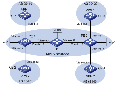
|
Device |
Interface |
IP address |
Device |
Interface |
IP address |
|
CE 1 |
Vlan-int11 |
2001:1::1/96 |
P |
Loop0 |
2.2.2.9/32 |
|
PE 1 |
Loop0 |
1.1.1.9/32 |
|
Vlan-int12 |
172.2.1.1/24 |
|
|
Vlan-int11 |
2001:1::2/96 |
|
Vlan-int13 |
172.1.1.2/24 |
|
|
Vlan-int13 |
172.1.1.1/24 |
PE 2 |
Loop0 |
3.3.3.9/32 |
|
|
Vlan-int12 |
2001:2::2/96 |
|
Vlan-int12 |
172.2.1.2/24 |
|
CE 2 |
Vlan-int12 |
2001:2::1/96 |
|
Vlan-int11 |
2001:3::2/96 |
|
CE 3 |
Vlan-int11 |
2001:3::1/96 |
|
Vlan-int13 |
2001:4::2/96 |
|
CE 4 |
Vlan-int13 |
2001:4::1/96 |
|
|
|
Configuration procedure
1. Configure OSPF on the MPLS backbone to achieve IP connectivity among the PEs and the P switch.
# Configure PE 1.
<PE1> system-view
[PE1] interface loopback 0
[PE1-LoopBack0] ip address 1.1.1.9 32
[PE1-LoopBack0] quit
[PE1] interface vlan-interface 13
[PE1-Vlan-interface13] ip address 172.1.1.1 24
[PE1- Vlan-interface13] quit
[PE1] ospf
[PE1-ospf-1] area 0
[PE1-ospf-1-area-0.0.0.0] network 172.1.1.0 0.0.0.255
[PE1-ospf-1-area-0.0.0.0] network 1.1.1.9 0.0.0.0
[PE1-ospf-1-area-0.0.0.0] quit
[PE1-ospf-1] quit
# Configure the P switch.
<P> system-view
[P] interface loopback 0
[P-LoopBack0] ip address 2.2.2.9 32
[P-LoopBack0] quit
[P] interface vlan-interface 13
[P-Vlan-interface13] ip address 172.1.1.2 24
[P- Vlan-interface13] quit
[P] interface vlan-interface 12
[P-Vlan-interface12] ip address 172.2.1.1 24
[P-Vlan-interface12] quit
[P] ospf
[P-ospf-1] area 0
[P-ospf-1-area-0.0.0.0] network 172.1.1.0 0.0.0.255
[P-ospf-1-area-0.0.0.0] network 172.2.1.0 0.0.0.255
[P-ospf-1-area-0.0.0.0] network 2.2.2.9 0.0.0.0
[P-ospf-1-area-0.0.0.0] quit
[P-ospf-1] quit
# Configure PE 2.
<PE2> system-view
[PE2] interface loopback 0
[PE2-LoopBack0] ip address 3.3.3.9 32
[PE2-LoopBack0] quit
[PE2] interface vlan-interface 12
[PE2-Vlan-interface12] ip address 172.2.1.2 24
[PE2-Vlan-interface12] quit
[PE2] ospf
[PE2-ospf-1] area 0
[PE2-ospf-1-area-0.0.0.0] network 172.2.1.0 0.0.0.255
[PE2-ospf-1-area-0.0.0.0] network 3.3.3.9 0.0.0.0
[PE2-ospf-1-area-0.0.0.0] quit
[PE2-ospf-1] quit
After you complete the previous configuration, OSPF adjacencies are established between PE 1, P, and PE 2. Issue the display ospf peer command. You can see that the adjacency status is Full. Issue the display ip routing-table command. You can see that the PEs have learned the routes to the loopback interfaces of each other. The following takes PE 1 as an example:
[PE1] display ip routing-table
Routing Tables: Public
Destinations : 9 Routes : 9
Destination/Mask Proto Pre Cost NextHop Interface
1.1.1.9/32 Direct 0 0 127.0.0.1 InLoop0
2.2.2.9/32 OSPF 10 1 172.1.1.2 Vlan13
3.3.3.9/32 OSPF 10 2 172.1.1.2 Vlan13
127.0.0.0/8 Direct 0 0 127.0.0.1 InLoop0
127.0.0.1/32 Direct 0 0 127.0.0.1 InLoop0
172.1.1.0/24 Direct 0 0 172.1.1.1 Vlan13
172.1.1.1/32 Direct 0 0 127.0.0.1 InLoop0
172.1.1.2/32 Direct 0 0 172.1.1.2 Vlan13
172.2.1.0/24 OSPF 10 1 172.1.1.2 Vlan13
[PE1] display ospf peer verbose
OSPF Process 1 with Router ID 1.1.1.9
Neighbors
Area 0.0.0.0 interface 172.1.1.1(Vlan-interface13)'s neighbors
Router ID: 172.1.1.2 Address: 172.1.1.2 GR State: Normal
State: Full Mode:Nbr is Master Priority: 1
DR: None BDR: None MTU: 1500
Dead timer due in 38 sec
Neighbor is up for 00:02:44
Authentication Sequence: [ 0 ]
Neighbor state change count: 5
2. Configure basic MPLS and enable MPLS LDP on the MPLS backbone to establish LDP LSPs.
# Configure PE 1.
[PE1] mpls lsr-id 1.1.1.9
[PE1] mpls
[PE1-mpls] quit
[PE1] mpls ldp
[PE1-mpls-ldp] quit
[PE1] interface vlan-interface 13
[PE1-Vlan-interface13] mpls
[PE1-Vlan-interface13] mpls ldp
[PE1-Vlan-interface13] quit
# Configure the P switch.
[P] mpls lsr-id 2.2.2.9
[P] mpls
[P-mpls] quit
[P] mpls ldp
[P-mpls-ldp] quit
[P] interface vlan-interface 13
[P-Vlan-interface13] mpls
[P-Vlan-interface13] mpls ldp
[P-Vlan-interface13] quit
[P] interface vlan-interface 12
[P-Vlan-interface12] mpls
[P-Vlan0interface12] mpls ldp
[P-Vlan-interface12] quit
# Configure PE 2.
[PE2] mpls lsr-id 3.3.3.9
[PE2] mpls
[PE2-mpls] quit
[PE2] mpls ldp
[PE2-mpls-ldp] quit
[PE2] interface vlan-interface 12
[PE2-Vlan-interface12] mpls
[PE2-Vlan-interface12] mpls ldp
[PE2-Vlan-interface12] quit
After you complete the previous configuration, LDP sessions are established between PE 1, P, and PE 2. Issue the display mpls ldp session command. You can see that the session status is Operational. Issue the display mpls ldp lsp command. You can see the LSPs established by LDP. The following takes PE 1 as an example:
[PE1] display mpls ldp session
LDP Session(s) in Public Network
Total number of sessions: 1
----------------------------------------------------------------
Peer-ID Status LAM SsnRole FT MD5 KA-Sent/Rcv
---------------------------------------------------------------
2.2.2.9:0 Operational DU Passive Off Off 5/5
---------------------------------------------------------------
LAM : Label Advertisement Mode FT : Fault Tolerance
[PE1] display mpls ldp lsp
LDP LSP Information
------------------------------------------------------------------
SN DestAddress/Mask In/OutLabel Next-Hop In/Out-Interface
------------------------------------------------------------------
1 1.1.1.9/32 3/NULL 127.0.0.1 Vlan-interface13/InLoop0
2 2.2.2.9/32 NULL/3 172.1.1.2 -------/Vlan-interface13
3 3.3.3.9/32 NULL/1024 172.1.1.2 -------/Vlan-interface13
------------------------------------------------------------------
A '*' before an LSP means the LSP is not established
A '*' before a Label means the USCB or DSCB is stale
3. Configure VPN instances on the PEs to allow the CEs to access.
# Configure PE 1.
[PE1] ip vpn-instance vpn1
[PE1-vpn-instance-vpn1] route-distinguisher 100:1
[PE1-vpn-instance-vpn1] vpn-target 111:1
[PE1-vpn-instance-vpn1] quit
[PE1] ip vpn-instance vpn2
[PE1-vpn-instance-vpn2] route-distinguisher 100:2
[PE1-vpn-instance-vpn2] vpn-target 222:2
[PE1-vpn-instance-vpn2] quit
[PE1] interface vlan-interface 11
[PE1-Vlan-interface11] ip binding vpn-instance vpn1
[PE1-Vlan-interface11] ipv6 address 2001:1::2 96
[PE1-Vlan-interface11] quit
[PE1] interface vlan-interface 12
[PE1-Vlan-interface12] ip binding vpn-instance vpn2
[PE1-Vlan-interface12] ipv6 address 2001:2::2 96
[PE1-Vlan-interface12] quit
# Configure PE 2.
[PE2] ip vpn-instance vpn1
[PE2-vpn-instance-vpn1] route-distinguisher 200:1
[PE2-vpn-instance-vpn1] vpn-target 111:1
[PE2-vpn-instance-vpn1] quit
[PE2] ip vpn-instance vpn2
[PE2-vpn-instance-vpn2] route-distinguisher 200:2
[PE2-vpn-instance-vpn2] vpn-target 222:2
[PE2-vpn-instance-vpn2] quit
[PE2] interface vlan-interface 11
[PE2-Vlan-interface11] ip binding vpn-instance vpn1
[PE2-Vlan-interface11] ipv6 address 2001:3::2 96
[PE2-Vlan-interface11] quit
[PE2] interface vlan-interface 13
[PE2-Vlan-interface13] ip binding vpn-instance vpn2
[PE2-Vlan-interface13] ipv6 address 2001:4::2 96
[PE2-Vlan-interface13] quit
# Configure IP addresses for the CEs as required in Figure 36. (Details not shown)
After you complete the previous configuration, issue the display ip vpn-instance command on the PEs to view the configuration of the VPN instance. Use the ping command to test connectivity between the PEs and their attached CEs. The PEs can ping their attached CEs. The following takes PE 1 as an example:
[PE1] display ip vpn-instance
Total VPN-Instances configured : 2
VPN-Instance Name RD Create Time
vpn1 100:1 2006/08/13 09:32:45
vpn2 100:2 2006/08/13 09:42:59
[PE1] ping ipv6 -vpn-instance vpn1 2001:1::1
PING 2001:1::1 : 56 data bytes, press CTRL_C to break
Reply from 2001:1::1
bytes=56 Sequence=1 hop limit=64 time = 1 ms
Reply from 2001:1::1
bytes=56 Sequence=2 hop limit=64 time = 1 ms
Reply from 2001:1::1
bytes=56 Sequence=3 hop limit=64 time = 1 ms
Reply from 2001:1::1
bytes=56 Sequence=4 hop limit=64 time = 1 ms
Reply from 2001:1::1
bytes=56 Sequence=5 hop limit=64 time = 1 ms
--- 2001:1::1 ping statistics ---
5 packet(s) transmitted
5 packet(s) received
0.00% packet loss
round-trip min/avg/max = 1/1/1 ms
4. Establish EBGP peer relationships between the PEs and CEs to allow them to exchange VPN routes.
# Configure CE 1.
<CE1> system-view
[CE1] bgp 65410
[CE1-bgp] ipv6-family
[CE1-bgp-af-ipv6] peer 2001:1::2 as-number 100
[CE1-bgp-af-ipv6] import-route direct
[CE1-bgp-af-ipv6] quit
|
|
NOTE: The configurations for the other three CEs (CE 2 through CE 4) are similar. (Details not shown) |
# Configure PE 1.
[PE1] bgp 100
[PE1-bgp] ipv6-family vpn-instance vpn1
[PE1-bgp-ipv6-vpn1] peer 2001:1::1 as-number 65410
[PE1-bgp-ipv6-vpn1] import-route direct
[PE1-bgp-ipv6-vpn1] quit
[PE1-bgp] ipv6-family vpn-instance vpn2
[PE1-bgp-ipv6-vpn2] peer 2001:2::1 as-number 65420
[PE1-bgp-ipv6-vpn2] import-route direct
[PE1-bgp-ipv6-vpn2] quit
[PE1-bgp] quit
|
|
NOTE: The configurations for PE 2 are similar to those for PE 1. (Details not shown) |
After you complete the previous configuration, issue the display bgp vpnv6 vpn-instance peer command on the PEs. You can see that a BGP peer relationship in Established state has been established between PE and CE switches. The following takes the PE 1-CE 1 BGP peer relationship as an example:
[PE1] display bgp vpnv6 vpn-instance vpn1 peer
BGP local router ID : 1.1.1.9
Local AS number : 100
Total number of peers : 1 Peers in established state : 1
Peer AS MsgRcvd MsgSent OutQ PrefRcv Up/Down State
2001:1::1 65410 11 9 0 1 00:06:37 Established
5. Configure an MP-IBGP peer relationship between the PEs.
# Configure PE 1.
[PE1] bgp 100
[PE1-bgp] peer 3.3.3.9 as-number 100
[PE1-bgp] peer 3.3.3.9 connect-interface loopback 0
[PE1-bgp] ipv6-family vpnv6
[PE1-bgp-af-vpnv6] peer 3.3.3.9 enable
[PE1-bgp-af-vpnv6] quit
[PE1-bgp] quit
# Configure PE 2.
[PE2] bgp 100
[PE2-bgp] peer 1.1.1.9 as-number 100
[PE2-bgp] peer 1.1.1.9 connect-interface loopback 0
[PE2-bgp] ipv6-family vpnv6
[PE2-bgp-af-vpnv6] peer 1.1.1.9 enable
[PE2-bgp-af-vpnv6] quit
[PE2-bgp] quit
After you complete the previous configuration, issue the display bgp peer command or the display bgp vpnv6 all peer command on the PEs. You can see a BGP peer relationship in Established state has been established between the PEs.
[PE1] display bgp peer
BGP local router ID : 1.1.1.9
Local AS number : 100
Total number of peers : 1 Peers in established state : 1
Peer AS MsgRcvd MsgSent OutQ PrefRcv Up/Down State
3.3.3.9 100 2 6 0 0 00:00:12 Established
6. Verify your configuration.
# Issue the display ipv6 routing-table vpn-instance command on the PEs, you can see the routes to the CEs. The following takes PE 1 as an example:
[PE1] display ipv6 routing-table vpn-instance vpn1
Routing Table :
Destinations : 3 Routes : 3
Destination: 2001:1::/96 Protocol : Direct
NextHop : 2001:1::2 Preference: 0
Interface : Vlan11 Cost : 0
Destination: 2001:1::2/128 Protocol : Direct
NextHop : ::1 Preference: 0
Interface : InLoop0 Cost : 0
Destination: 2001:2::/96 Protocol : BGP4+
NextHop : ::FFFF:303:309 Preference: 0
Interface : NULL0 Cost : 0
[PE1] display ipv6 routing-table vpn-instance vpn2
Routing Table :
Destinations : 3 Routes : 3
Destination: 2001:3::/96 Protocol : Direct
NextHop : 2001:3::2 Preference: 0
Interface : Vlan12 Cost : 0
Destination: 2001:3::2/128 Protocol : Direct
NextHop : ::1 Preference: 0
Interface : InLoop0 Cost : 0
Destination: 2001:4::/96 Protocol : BGP4+
NextHop : ::FFFF:303:309 Preference: 0
Interface : NULL0 Cost : 0
# From each CE, ping other CEs. CEs of the same VPN can ping each other, whereas those of different VPNs are not. For example, CE 1 can ping CE 3 (2001:3::1), but it cannot ping CE 4 (2001:4::1):
[CE1] ping ipv6 2001:3::1
PING 2001:3::1 : 56 data bytes, press CTRL_C to break
Reply from 2001:3::1
bytes=56 Sequence=1 hop limit=64 time = 1 ms
Reply from 2001:3::1
bytes=56 Sequence=2 hop limit=64 time = 1 ms
Reply from 2001:3::1
bytes=56 Sequence=3 hop limit=64 time = 1 ms
Reply from 2001:3::1
bytes=56 Sequence=4 hop limit=64 time = 1 ms
Reply from 2001:3::1
bytes=56 Sequence=5 hop limit=64 time = 1 ms
--- 2001:3::1 ping statistics ---
5 packet(s) transmitted
5 packet(s) received
0.00% packet loss
round-trip min/avg/max = 1/1/1 ms
[CE1] ping ipv6 2001:4::1
PING 2001:4::1 : 56 data bytes, press CTRL_C to break
Request time out
Request time out
Request time out
Request time out
Request time out
--- 2001:4::1 ping statistics ---
5 packet(s) transmitted
0 packet(s) received
100.00% packet loss
round-trip min/avg/max = 0/0/0 ms
Configuring inter-AS IPv6 VPN option A
Network requirements
CE 1 is connected to PE 1 and CE 2 is connected to PE 2. PE 1 and PE 2 are in different ASs.
Configure OSPF in each MPLS backbone.
Configure an inter-AS IPv6 MPLS L3VPN using option A, so CE 1 and CE 2 can communicate with each other within the VPN.
Figure 37 Network diagram
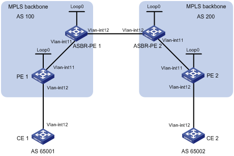
|
Device |
Interface |
IP address |
Device |
Interface |
IP address |
|
CE 1 |
Vlan-int12 |
2001:1::1/96 |
CE 2 |
Vlan-int12 |
2001:2::1/96 |
|
PE 1 |
Loop0 |
1.1.1.9/32 |
PE 2 |
Loop0 |
4.4.4.9/32 |
|
|
Vlan-int12 |
2001:1::2/96 |
|
Vlan-int12 |
2001:2::2/96 |
|
|
Vlan-int11 |
172.1.1.2/24 |
|
Vlan-int11 |
162.1.1.2/24 |
|
ASBR-PE 1 |
Loop0 |
2.2.2.9/32 |
ASBR-PE 2 |
Loop0 |
3.3.3.9/32 |
|
|
Vlan-int11 |
172.1.1.1/24 |
|
Vlan-int11 |
162.1.1.1/24 |
|
|
Vlan-int12 |
2002:1::1/96 |
|
Vlan-int12 |
2002:1::2/96 |
Configuration procedure
1. Configure an IGP on each MPLS backbone to implement IP connectivity within the backbone.
This example uses OSPF. (Details not shown)
|
|
NOTE: Be sure to advertise the 32-bit loopback interface address of each router through OSPF. The loopback interface address of a switch is to be used as the switch’s LSR ID. |
After you complete the previous configuration, each ASBR PE and the PE in the same AS can establish OSPF adjacencies. Issue the display ospf peer command. You can see that the adjacencies reach Full state, and that PE and ASBR PE routers in the same AS can learn the routes to the loopback interfaces of each other.
Each ASBR PE and the PE in the same AS can ping each other.
2. Configure basic MPLS and enable MPLS LDP on each MPLS backbone to establish LDP LSPs.
# Configure basic MPLS on PE 1 and enable MPLS LDP for PE 1 and for the interface connected to ASBR-PE 1.
<PE1> system-view
[PE1] mpls lsr-id 1.1.1.9
[PE1] mpls
[PE1-mpls] quit
[PE1] mpls ldp
[PE1-mpls-ldp] quit
[PE1] interface vlan-interface 11
[PE1-Vlan-interface11] mpls
[PE1-Vlan-interface11] mpls ldp
[PE1-Vlan-interface11] quit
# Configure basic MPLS on ASBR-PE 1 and enable MPLS LDP for ASBR-PE 1 and for the interface connected to PE 1.
<ASBR-PE1> system-view
[ASBR-PE1] mpls lsr-id 2.2.2.9
[ASBR-PE1] mpls
[ASBR-PE1-mpls] quit
[ASBR-PE1] mpls ldp
[ASBR-PE1-mpls-ldp] quit
[ASBR-PE1] interface vlan-interface 11
[ASBR-PE1-Vlan-interface11] mpls
[ASBR-PE1-Vlan-interface11] mpls ldp
[ASBR-PE1-Vlan-interface11] quit
# Configure basic MPLS on ASBR-PE 2 and enable MPLS LDP for ASBR-PE 2 and for the interface connected to PE 2.
<ASBR-PE2> system-view
[ASBR-PE2] mpls lsr-id 3.3.3.9
[ASBR-PE2] mpls
[ASBR-PE2-mpls] quit
[ASBR-PE2] mpls ldp
[ASBR-PE2-mpls-ldp] quit
[ASBR-PE2] interface vlan-interface 11
[ASBR-PE2-Vlan-interface11] mpls
[ASBR-PE2-Vlan-interface11] mpls ldp
[ASBR-PE2-Vlan-interface11] quit
# Configure basic MPLS on PE 2 and enable MPLS LDP for PE 2 for the interface connected to ASBR-PE 2.
<PE2> system-view
[PE2] mpls lsr-id 4.4.4.9
[PE2] mpls
[PE2-mpls] quit
[PE2] mpls ldp
[PE2-mpls-ldp] quit
[PE2] interface vlan-interface 11
[PE2-Vlan-interface11] mpls
[PE2-Vlan-interface11] mpls ldp
[PE2-Vlan-interface11] quit
After you complete the previous configuration, each PE and the ASBR PE in the same AS can establish LDP neighbor relationship. Issuing the display mpls ldp session command on the switches, you can see that the session status is Operational.
3. Configure a VPN instance on the PEs to allow the CEs to access.
|
|
NOTE: For the same VPN, the VPN targets for the VPN instance on the PE must match those for the VPN instance of the ASBR-PE in the same AS. This is not required for PEs in different ASs. |
# Configure CE 1.
<CE1> system-view
[CE1] interface vlan-interface 12
[CE1-Vlan-interface12] ipv6 address 2001:1::1 96
[CE1-Vlan-interface12] quit
# Configure PE 1.
[PE1] ip vpn-instance vpn1
[PE1-vpn-instance-vpn1] route-distinguisher 100:1
[PE1-vpn-instance-vpn1] vpn-target 100:1 both
[PE1-vpn-instance-vpn1] quit
[PE1] interface vlan-interface 12
[PE1-Vlan-interface12] ip binding vpn-instance vpn1
[PE1-Vlan-interface12] ipv6 address 2001:1::2 96
[PE1-Vlan-interface12] quit
# Configure CE 2.
<CE2> system-view
[CE2] interface vlan-interface 12
[CE2-Vlan-interface12] ipv6 address 2001:2::1 96
[CE2-Vlan-interface12] quit
# Configure PE 2.
[PE2] ip vpn-instance vpn1
[PE2-vpn-instance] route-distinguisher 200:2
[PE2-vpn-instance] vpn-target 100:1 both
[PE2-vpn-instance] quit
[PE2] interface vlan-interface 12
[PE2-Vlan-interface12] ip binding vpn-instance vpn1
[PE2-Vlan-interface12] ipv6 address 2001:2::2 96
[PE2-Vlan-interface12] quit
# Configure ASBR-PE 1, creating a VPN instance and binding the VPN instance to the interface connected to ASBR-PE 2 (ASBR-PE 1 considers ASBR-PE 2 its attached CE).
[ASBR-PE1] ip vpn-instance vpn1
[ASBR-PE1-vpn-instance-vpn1] route-distinguisher 100:1
[ASBR-PE1-vpn-instance-vpn1] vpn-target 100:1 both
[ASBR-PE1-vpn-instance-vpn1] quit
[ASBR-PE1] interface vlan-interface 12
[ASBR-PE1-Vlan-interface12] ip binding vpn-instance vpn1
[ASBR-PE1-Vlan-interface12] ip address 192.1.1.1 24
[ASBR-PE1-Vlan-interface12] quit
# Configure ASBR-PE 2, creating a VPN instance and binding the VPN instance to the interface connected to ASBR-PE 1 (ASBR-PE 2 considers ASBR-PE 1 its attached CE).
[ASBR-PE2] ip vpn-instance vpn1
[ASBR-PE2-vpn-vpn-vpn1] route-distinguisher 200:1
[ASBR-PE2-vpn-vpn-vpn1] vpn-target 100:1 both
[ASBR-PE2-vpn-vpn-vpn1] quit
[ASBR-PE2] interface vlan-interface 12
[ASBR-PE2-Vlan-interface12] ip binding vpn-instance vpn1
[ASBR-PE2-Vlan-interface12] ip address 192.1.1.2 24
[ASBR-PE2-Vlan-interface12] quit
After completing the previous configuration, you can see the VPN instance configurations by issuing the display ip vpn-instance command.
Each PE can ping its attached CE, and ASBR-PE 1 and ASBR-PE 2 can ping each other.
4. Establish EBGP peer relationship between PE and CE switches to allow VPN routes to be redistributed.
# Configure CE 1.
[CE1] bgp 65001
[CE1-bgp] ipv6-family
[CE1-bgp-af-ipv6] peer 2001:1::2 as-number 100
[CE1-bgp-af-ipv6] import-route direct
[CE1-bgp-af-ipv6] quit
# Configure PE 1.
[PE1] bgp 100
[PE1-bgp] ipv6-family vpn-instance vpn1
[PE1-bgp-ipv6-vpn1] peer 2001:1::1 as-number 65001
[PE1-bgp-ipv6-vpn1] import-route direct
[PE1-bgp-ipv6-vpn1] quit
[PE1-bgp] quit
# Configure CE 2.
[CE2] bgp 65002
[CE1-bgp] ipv6-family
[CE2-bgp-af-ipv6] peer 2001:2::2 as-number 200
[CE2-bgp-af-ipv6] import-route direct
[CE2-bgp-af-ipv6] quit
# Configure PE 2.
[PE2] bgp 200
[PE2-bgp] ipv6-family vpn-instance vpn1
[PE2-bgp-ipv6-vpn1] peer 2001:2::1 as-number 65002
[PE2-bgp-ipv6-vpn1] import-route direct
[PE2-bgp-ipv6-vpn1] quit
[PE2-bgp] quit
5. Establish IBGP peer relationship between each PE and the ASBR-PE in the same AS and EBGP peer relationship between the ASBR PEs.
# Configure PE 1.
[PE1] bgp 100
[PE1-bgp] peer 2.2.2.9 as-number 100
[PE1-bgp] peer 2.2.2.9 connect-interface loopback 0
[PE1-bgp] ipv6-family vpnv6
[PE1-bgp-af-vpnv6] peer 2.2.2.9 enable
[PE1-bgp-af-vpnv6] quit
# Configure ASBR-PE 1.
[ASBR-PE1] bgp 100
[ASBR-PE1-bgp] ipv6-family vpn-instance vpn1
[ASBR-PE1-bgp-ipv6-vpn1] peer 2002:1::2 as-number 200
[ASBR-PE1-bgp-ipv6-vpn1] quit
[ASBR-PE1-bgp] peer 1.1.1.9 as-number 100
[ASBR-PE1-bgp] peer 1.1.1.9 connect-interface loopback 0
[ASBR-PE1-bgp] ipv6-family vpnv6
[ASBR-PE1-bgp-af-vpnv6] peer 1.1.1.9 enable
[ASBR-PE1-bgp-af-vpnv6] quit
[ASBR-PE1-bgp] quit
# Configure ASBR-PE 2.
[ASBR-PE2] bgp 200
[ASBR-PE2-bgp] ipv6-family vpn-instance vpn1
[ASBR-PE2-bgp-ipv6-vpn1] peer 2002:1::1 as-number 100
[ASBR-PE2-bgp-ipv6-vpn1] quit
[ASBR-PE2-bgp] peer 4.4.4.9 as-number 200
[ASBR-PE2-bgp] peer 4.4.4.9 connect-interface loopback 0
[ASBR-PE2-bgp] ipv6-family vpnv6
[ASBR-PE2-bgp-af-vpnv6] peer 4.4.4.9 enable
[ASBR-PE2-bgp-af-vpnv6] quit
[ASBR-PE2-bgp] quit
# Configure PE 2.
[PE2] bgp 200
[PE2-bgp] peer 3.3.3.9 as-number 200
[PE2-bgp] peer 3.3.3.9 connect-interface loopback 0
[PE2-bgp] ipv6-family vpnv6
[PE2-bgp-af-vpnv6] peer 3.3.3.9 enable
[PE2-bgp-af-vpnv6] quit
[PE2-bgp] quit
6. Verify your configuration.
After you complete the previous configurations, display the routing table and use the ping command. The CEs have learned the route to each other and can ping each other.
Configuring inter-AS IPv6 VPN option C
Network requirements
Site 1 and Site 2 belong to the same VPN. Site 1 accesses the network through PE 1 in AS 100 and Site 2 accesses the network through PE 2 in AS 600.
PEs in the same AS run IS-IS. PE 1 and ASBR-PE 1 exchange labeled IPv4 routes by MP-IBGP. PE 2 and ASBR-PE 2 exchange labeled IPv4 routes by MP-IBGP. PE 1 and PE 2 are MP-EBGP peers.
ASBR-PE 1 and ASBR-PE 2 use their respective routing policies and label the routes received from each other. ASBR-PE 1 and ASBR-PE 2 use MP-EBGP to exchange labeled IPv4 routes.
Figure 38 Network diagram
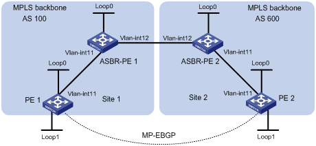
|
Device |
Interface |
IP address |
Device |
Interface |
IP address |
|
PE 1 |
Loop0 |
2.2.2.9/32 |
PE 2 |
Loop0 |
5.5.5.9/32 |
|
|
Loop1 |
2001:1::1/128 |
|
Loop1 |
2001:1::2/128 |
|
|
Vlan-int11 |
1.1.1.2/8 |
|
Vlan-int11 |
9.1.1.2/8 |
|
ASBR-PE 1 |
Loop0 |
3.3.3.9/32 |
ASBR-PE 2 |
Loop0 |
4.4.4.9/32 |
|
|
Vlan-int11 |
1.1.1.1/8 |
|
Vlan-int11 |
9.1.1.1/8 |
|
|
Vlan-int12 |
11.0.0.2/8 |
|
Vlan-int12 |
11.0.0.1/8 |
Configuration procedure
1. Configure PE 1.
# Run IS-IS on PE 1.
<PE1> system-view
[PE1] isis 1
[PE1-isis-1] network-entity 10.111.111.111.111.00
[PE1-isis-1] quit
# Configure an LSR ID, and enable MPLS and LDP.
[PE1] mpls lsr-id 2.2.2.9
[PE1] mpls
[PE1-mpls] quit
[PE1] mpls ldp
[PE1-mpls-ldp] quit
# Configure interface VLAN-interface 11, and start IS-IS and enable MPLS and LDP on the interface.
[PE1] interface vlan-interface 11
[PE1-Vlan-interface11] ip address 1.1.1.2 255.0.0.0
[PE1-Vlan-interface11] isis enable 1
[PE1-Vlan-interface11] mpls
[PE1-Vlan-interface11] mpls ldp
[PE1-Vlan-interface11] quit
# Configure interface Loopback 0 and start IS-IS on it.
[PE1] interface loopback 0
[PE1-LoopBack0] ip address 2.2.2.9 32
[PE1-LoopBack0] isis enable 1
[PE1-LoopBack0] quit
# Create VPN instance vpn1 and configure the RD and VPN target attributes for it.
[PE1] ip vpn-instance vpn1
[PE1-vpn-instance-vpn1] route-distinguisher 11:11
[PE1-vpn-instance-vpn1] vpn-target 3:3 import-extcommunity
[PE1-vpn-instance-vpn1] vpn-target 3:3 export-extcommunity
[PE1-vpn-instance-vpn1] quit
# Configure interface Loopback 1 and bind the interface to VPN instance vpn1.
[PE1] interface loopback 1
[PE1-LoopBack1] ip binding vpn-instance vpn1
[PE1-LoopBack1] ipv6 address 2001:1::1 128
[PE1-LoopBack1] quit
# Start BGP.
[PE1] bgp 100
# Configure the capability to advertise labeled routes to and receive labeled routes from the IBGP peer 3.3.3.9.
[PE1-bgp] peer 3.3.3.9 as-number 100
[PE1-bgp] peer 3.3.3.9 connect-interface loopback 0
[PE1-bgp] peer 3.3.3.9 label-route-capability
# Configure the maximum hop count from PE 1 to EBGP peer 5.5.5.9 as 10.
[PE1-bgp] peer 5.5.5.9 as-number 600
[PE1-bgp] peer 5.5.5.9 connect-interface loopback 0
[PE1-bgp] peer 5.5.5.9 ebgp-max-hop 10
# Configure peer 5.5.5.9 as a VPNv6 peer.
[PE1-bgp] ipv6-family vpnv6
[PE1-bgp-af-vpnv6] peer 5.5.5.9 enable
[PE1-bgp-af-vpnv6] quit
# Redistribute direct routes to the routing table of vpn1.
[PE1-bgp] ipv6-family vpn-instance vpn1
[PE1-bgp-ipv6-vpn1] import-route direct
[PE1-bgp-ipv6-vpn1] quit
[PE1-bgp] quit
2. Configure ASBR-PE 1.
# Start IS-IS on ASBR-PE 1.
<ASBR-PE1> system-view
[ASBR-PE1] isis 1
[ASBR-PE1-isis-1] network-entity 10.222.222.222.222.00
[ASBR-PE1-isis-1] quit
# Configure an LSR ID, and enable MPLS and LDP.
[ASBR-PE1] mpls lsr-id 3.3.3.9
[ASBR-PE1] mpls
[ASBR-PE1-mpls] quit
[ASBR-PE1] mpls ldp
[ASBR-PE1-mpls-ldp] quit
# Configure interface VLAN-interface 11, and start IS-IS and enable MPLS and LDP on the interface.
[ASBR-PE1] interface vlan-interface 11
[ASBR-PE1-Vlan-interface11] ip address 1.1.1.1 255.0.0.0
[ASBR-PE1-Vlan-interface11] isis enable 1
[ASBR-PE1-Vlan-interface11] mpls
[ASBR-PE1-Vlan-interface11] mpls ldp
[ASBR-PE1-Vlan-interface11] quit
# Configure interface VLAN-interface 12 and enable MPLS on it.
[ASBR-PE1] interface vlan-interface 12
[ASBR-PE1-Vlan-interface12] ip address 11.0.0.2 255.0.0.0
[ASBR-PE1-Vlan-interface12] mpls
[ASBR-PE1-Vlan-interface12] quit
# Configure interface Loopback 0 and start IS-IS on it.
[ASBR-PE1] interface loopback 0
[ASBR-PE1-LoopBack0] ip address 3.3.3.9 32
[ASBR-PE1-LoopBack0] isis enable 1
[ASBR-PE1-LoopBack0] quit
# Create routing policies.
[ASBR-PE1] route-policy policy1 permit node 1
[ASBR-PE1-route-policy1] apply mpls-label
[ASBR-PE1-route-policy1] quit
[ASBR-PE1] route-policy policy2 permit node 1
[ASBR-PE1-route-policy2] if-match mpls-label
[ASBR-PE1-route-policy2] apply mpls-label
[ASBR-PE1-route-policy2] quit
# Start BGP on ASBR-PE 1 and redistribute routes from IS-IS process 1.
[ASBR-PE1] bgp 100
[ASBR-PE1-bgp] import-route isis 1
# Apply routing policy policy2 to filter routes advertised to IBGP peer 2.2.2.9.
[ASBR-PE1-bgp] peer 2.2.2.9 as-number 100
[ASBR-PE1-bgp] peer 2.2.2.9 route-policy policy2 export
# Configure the capability to advertise labeled routes to and receive labeled routes from IBGP peer 2.2.2.9.
[ASBR-PE1-bgp] peer 2.2.2.9 connect-interface loopback 0
[ASBR-PE1-bgp] peer 2.2.2.9 label-route-capability
# Apply routing policy policy1 to filter routes advertised to EBGP peer 11.0.0.1.
[ASBR-PE1-bgp] peer 11.0.0.1 as-number 600
[ASBR-PE1-bgp] peer 11.0.0.1 route-policy policy1 export
# Configure the capability to advertise labeled routes to and receive labeled routes from EBGP peer 11.0.0.1.
[ASBR-PE1-bgp] peer 11.0.0.1 label-route-capability
[ASBR-PE1-bgp] quit
3. Configure ASBR-PE 2.
# Start IS-IS on ASBR-PE 2.
<ASBR-PE2> system-view
[ASBR-PE2] isis 1
[ASBR-PE2-isis-1] network-entity 10.333.333.333.333.00
[ASBR-PE2-isis-1] quit
# Configure an LSR ID, enable MPLS and LDP.
[ASBR-PE2] mpls lsr-id 4.4.4.9
[ASBR-PE2] mpls
[ASBR-PE2-mpls] quit
[ASBR-PE2] mpls ldp
[ASBR-PE2-mpls-ldp] quit
# Configure interface VLAN-interface 11, start IS-IS and enable MPLS and LDP on the interface.
[ASBR-PE2] interface vlan-interface 11
[ASBR-PE2-Vlan-interface11] ip address 9.1.1.1 255.0.0.0
[ASBR-PE2-Vlan-interface11] isis enable 1
[ASBR-PE2-Vlan-interface11] mpls
[ASBR-PE2-Vlan-interface11] mpls ldp
[ASBR-PE2-Vlan-interface11] quit
# Configure interface Loopback 0 and start IS-IS on it.
[ASBR-PE2] interface loopback 0
[ASBR-PE2-LoopBack0] ip address 4.4.4.9 32
[ASBR-PE2-LoopBack0] isis enable 1
[ASBR-PE2-LoopBack0] quit
# Configure interface VLAN-interface 12 and enable MPLS on it.
[ASBR-PE2] interface vlan-interface 12
[ASBR-PE2-Vlan-interface12] ip address 11.0.0.1 255.0.0.0
[ASBR-PE2-Vlan-interface12] mpls
[ASBR-PE2-Vlan-interface12] quit
# Create routing policies.
[ASBR-PE2] route-policy policy1 permit node 1
[ASBR-PE2-route-policy1] apply mpls-label
[ASBR-PE2-route-policy1] quit
[ASBR-PE2] route-policy policy2 permit node 1
[ASBR-PE2-route-policy2] if-match mpls-label
[ASBR-PE2-route-policy2] apply mpls-label
[ASBR-PE2-route-policy2] quit
# Start BGP on ASBR-PE 2 and redistribute routes from IS-IS process 1.
[ASBR-PE2] bgp 600
[ASBR-PE2-bgp] import-route isis 1
# Configure the capability to advertise labeled routes to and receive labeled routes from IBGP peer 5.5.5.9.
[ASBR-PE2-bgp] peer 5.5.5.9 as-number 600
[ASBR-PE2-bgp] peer 5.5.5.9 connect-interface loopback 0
[ASBR-PE2-bgp] peer 5.5.5.9 label-route-capability
# Apply routing policy policy2 to filter routes advertised to IBGP peer 5.5.5.9.
[ASBR-PE2-bgp] peer 5.5.5.9 route-policy policy2 export
# Apply routing policy policy1 to filter routes advertised to EBGP peer 11.0.0.2.
[ASBR-PE2-bgp] peer 11.0.0.2 as-number 100
[ASBR-PE2-bgp] peer 11.0.0.2 route-policy policy1 export
# Configure the capability to advertise labeled routes to and receive labeled routes from EBGP peer 11.0.0.2.
[ASBR-PE2-bgp] peer 11.0.0.2 label-route-capability
[ASBR-PE2-bgp] quit
4. Configure PE 2.
# Start IS-IS on PE 2.
<PE2> system-view
[PE2] isis 1
[PE2-isis-1] network-entity 10.444.444.444.444.00
[PE2-isis-1] quit
# Configure an LSR ID, and enable MPLS and LDP.
[PE2] mpls lsr-id 5.5.5.9
[PE2] mpls
[PE2-mpls] quit
[PE2] mpls ldp
[PE2-mpls-ldp] quit
# Configure interface VLAN-interface 11, and start IS-IS and enable MPLS and LDP on the interface.
[PE2] interface vlan-interface 11
[PE2-Vlan-interface11] ip address 9.1.1.2 255.0.0.0
[PE2-Vlan-interface11] isis enable 1
[PE2-Vlan-interface11] mpls
[PE2-Vlan-interface11] mpls ldp
[PE2-Vlan-interface11] quit
# Configure interface Loopback 0 and start IS-IS on it.
[PE2] interface loopback 0
[PE2-LoopBack0] ip address 5.5.5.9 32
[PE2-LoopBack0] isis enable 1
[PE2-LoopBack0] quit
# Create VPN instance vpn1 and configure the RD and VPN target attributes for it.
[PE2] ip vpn-instance vpn1
[PE2-vpn-instance-vpn1] route-distinguisher 11:11
[PE2-vpn-instance-vpn1] vpn-target 3:3 import-extcommunity
[PE2-vpn-instance-vpn1] vpn-target 3:3 export-extcommunity
[PE2-vpn-instance-vpn1] quit
# Configure interface Loopback 1 and bind the interface to VPN instance vpn1.
[PE2] interface loopback 1
[PE2-LoopBack1] ip binding vpn-instance vpn1
[PE2-LoopBack1] ipv6 address 2001:1::2 128
[PE2-LoopBack1] quit
# Start BGP on PE 2.
[PE2] bgp 600
# Configure the capability to advertise labeled routes to IBGP peer 4.4.4.9 and to receive labeled routes from the peer.
[PE2-bgp] peer 4.4.4.9 as-number 600
[PE2-bgp] peer 4.4.4.9 connect-interface loopback 0
[PE2-bgp] peer 4.4.4.9 label-route-capability
# Configure the maximum hop count from PE 2 to EBGP peer 2.2.2.9 as 10.
[PE2-bgp] peer 2.2.2.9 as-number 100
[PE2-bgp] peer 2.2.2.9 connect-interface loopback 0
[PE2-bgp] peer 2.2.2.9 ebgp-max-hop 10
# Configure peer 2.2.2.9 as a VPNv6 peer.
[PE2-bgp] ipv6-family vpnv6
[PE2-bgp-af-vpnv6] peer 2.2.2.9 enable
[PE2-bgp-af-vpnv6] quit
# Redistribute direct routes to the routing table of vpn1.
[PE2-bgp] ipv6-family vpn-instance vpn1
[PE2-bgp-ipv6-vpn1] import-route direct
[PE2-bgp-ipv6-vpn1] quit
[PE2-bgp] quit
5. Verify your configuration.
# From each PE, ping the other PE. PE 1 and PE 2 can ping each other:
[PE2] ping ipv6 –vpn-instance vpn1 2001:1::1
PING 2001:1::1 : 56 data bytes, press CTRL_C to break
Reply from 2001:1::1
bytes=56 Sequence=1 hop limit=64 time = 1 ms
Reply from 2001:1::1
bytes=56 Sequence=2 hop limit=64 time = 1 ms
Reply from 2001:1::1
bytes=56 Sequence=3 hop limit=64 time = 1 ms
Reply from 2001:1::1
bytes=56 Sequence=4 hop limit=64 time = 1 ms
Reply from 2001:1::1
bytes=56 Sequence=5 hop limit=64 time = 1 ms
--- 2001:1::1 ping statistics ---
5 packet(s) transmitted
5 packet(s) received
0.00% packet loss
round-trip min/avg/max = 1/1/1 ms
[PE1] ping ipv6 –vpn-instance vpn1 2001:1::2
PING 2001:1::2 : 56 data bytes, press CTRL_C to break
Reply from 2001:1::2
bytes=56 Sequence=1 hop limit=64 time = 1 ms
Reply from 2001:1::2
bytes=56 Sequence=2 hop limit=64 time = 1 ms
Reply from 2001:1::2
bytes=56 Sequence=3 hop limit=64 time = 1 ms
Reply from 2001:1::2
bytes=56 Sequence=4 hop limit=64 time = 1 ms
Reply from 2001:1::2
bytes=56 Sequence=5 hop limit=64 time = 1 ms
--- 2001:1::2 ping statistics ---
5 packet(s) transmitted
5 packet(s) received
0.00% packet loss
round-trip min/avg/max = 1/1/1 ms
Configuring carrier’s carrier
Network requirements
Configure carrier’s carrier for the scenario shown in Figure 39. In this scenario:
· PE 1 and PE 2 are the provider carrier’s PE switches. They provide VPN services for the customer carrier.
· CE 1 and CE 2 are the customer carrier’s switches. They connect to the provider carrier’s backbone as CE switches.
· PE 3 and PE 4 are the customer carrier’s PE switches. They provide IPv6 MPLS L3VPN services for the end customers.
· CE 3 and CE 4 are customers of the customer carrier.
The key to the carrier’s carrier deployment is to configure exchange of two kinds of routes:
· Exchange of the customer carrier’s internal routes on the provider carrier’s backbone.
· Exchange of the end customers’ internal routes between PE 3 and PE 4, the PEs of the customer carrier. In this process, an MP-IBGP peer relationship must be established between PE 3 and PE 4.
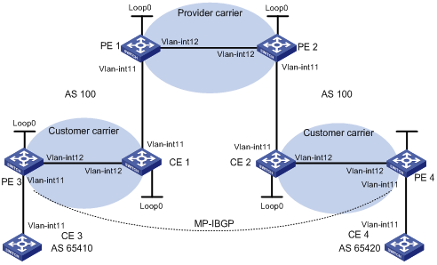
|
Device |
Interface |
IP address |
Device |
Interface |
IP address |
|
CE 3 |
Vlan-int11 |
2001:1::1/96 |
CE 4 |
Vlan-int11 |
2001:2::1/96 |
|
PE 3 |
Loop0 |
1.1.1.9/32 |
PE 4 |
Loop0 |
6.6.6.9/32 |
|
|
Vlan-int11 |
2001:1::2/96 |
|
Vlan-int11 |
2001:2::2/96 |
|
|
Vlan-int12 |
10.1.1.1/24 |
|
Vlan-int12 |
20.1.1.2/24 |
|
CE 1 |
Loop0 |
2.2.2.9/32 |
CE 2 |
Loop0 |
5.5.5.9/32 |
|
|
Vlan-int12 |
10.1.1.2/24 |
|
Vlan-int11 |
21.1.1.2/24 |
|
|
Vlan-int11 |
11.1.1.1/24 |
|
Vlan-int12 |
20.1.1.1/24 |
|
PE 1 |
Loop0 |
3.3.3.9/32 |
PE 2 |
Loop0 |
4.4.4.9/32 |
|
|
Vlan-int11 |
11.1.1.2/24 |
|
Vlan-int12 |
30.1.1.2/24 |
|
|
Vlan-int12 |
30.1.1.1/24 |
|
Vlan-int11 |
21.1.1.1/24 |
Configuration procedure
1. Configure MPLS L3VPN on the provider carrier backbone: start IS-IS as the IGP, enable LDP on PE 1 and PE 2, and establish MP-IBGP peer relationship between the PEs.
# Configure PE 1.
<PE1> system-view
[PE1] interface loopback 0
[PE1-LoopBack0] ip address 3.3.3.9 32
[PE1-LoopBack0] quit
[PE1] mpls lsr-id 3.3.3.9
[PE1] mpls
[PE1-mpls] quit
[PE1] mpls ldp
[PE1-mpls-ldp] quit
[PE1] isis 1
[PE1-isis-1] network-entity 10.0000.0000.0000.0004.00
[PE1-isis-1] quit
[PE1] interface loopback 0
[PE1-LoopBack0] isis enable 1
[PE1-LoopBack0] quit
[PE1] interface vlan-interface 12
[PE1-Vlan-interface12] ip address 30.1.1.1 24
[PE1-Vlan-interface12] isis enable 1
[PE1-Vlan-interface12] mpls
[PE1-Vlan-interface12] mpls ldp
[PE1-Vlan-interface2] mpls ldp transport-address interface
[PE1-Vlan-interface2] quit
[PE1] bgp 100
[PE1-bgp] peer 4.4.4.9 as-number 100
[PE1-bgp] peer 4.4.4.9 connect-interface loopback 0
[PE1-bgp] ipv4-family vpnv4
[PE1-bgp-af-vpnv4] peer 4.4.4.9 enable
[PE1-bgp-af-vpnv4] quit
[PE1-bgp] quit
|
|
NOTE: The configurations for PE 2 are similar to those for PE 1. (Details not shown) |
After you complete the previous configuration, issue the display mpls ldp session command on PE 1 or PE 2. You can see that an LDP session has been established successfully. Issue the display bgp peer command, and you can see that a BGP peer relationship in Established state has been established. Issue the display isis peer command, and you can see that an IS-IS neighbor relationship has been set up. Take PE 1 as an example:
[PE1] display mpls ldp session
LDP Session(s) in Public Network
Total number of sessions: 1
----------------------------------------------------------------
Peer-ID Status LAM SsnRole FT MD5 KA-Sent/Rcv
----------------------------------------------------------------
4.4.4.9:0 Operational DU Active Off Off 378/378
----------------------------------------------------------------
LAM : Label Advertisement Mode FT : Fault Tolerance
[PE1] display bgp peer
BGP local router ID : 3.3.3.9
Local AS number : 100
Total number of peers : 1 Peers in established state : 1
Peer AS MsgRcvd MsgSent OutQ PrefRcv Up/Down State
4.4.4.9 100 162 145 0 0 02:12:47 Established
[PE1] display isis peer
Peer information for ISIS(1)
----------------------------
System Id Interface Circuit Id State HoldTime Type PRI
0000.0000.0005 Vlan-interface12 001 Up 29s L1L2 --
2. Configure the customer carrier network: start IS-IS as the IGP, and enable LDP between PE 3 and CE 1, and between PE 4 and CE 2.
# Configure PE 3.
<PE3> system-view
[PE3] interface loopback 0
[PE3-LoopBack0] ip address 1.1.1.9 32
[PE3-LoopBack0] quit
[PE3] mpls lsr-id 1.1.1.9
[PE3] mpls
[PE3-mpls] quit
[PE3] mpls ldp
[PE3-mpls-ldp] quit
[PE3] isis 2
[PE3-isis-2] network-entity 10.0000.0000.0000.0001.00
[PE3-isis-2] quit
[PE3] interface loopback 0
[PE3-LoopBack0] isis enable 2
[PE3-LoopBack0] quit
[PE3] interface vlan-interface 12
[PE3-Vlan-interface12] ip address 10.1.1.1 24
[PE3-Vlan-interface12] isis enable 2
[PE3-Vlan-interface12] mpls
[PE3-Vlan-interface12] mpls ldp
[PE3-Vlan-interface12] mpls ldp transport-address interface
[PE3-Vlan-interface12] quit
# Configure CE 1.
<CE1> system-view
[CE1] interface loopback 0
[CE1-LoopBack0] ip address 2.2.2.9 32
[CE1-LoopBack0] quit
[CE1] mpls lsr-id 2.2.2.9
[CE1] mpls
[CE1-mpls] quit
[CE1] mpls ldp
[CE1-mpls-ldp] quit
[CE1] isis 2
[CE1-isis-2] network-entity 10.0000.0000.0000.0002.00
[CE1-isis-2] quit
[CE1] interface loopback 0
[CE1-LoopBack0] isis enable 2
[CE1-LoopBack0] quit
[CE1] interface vlan-interface 12
[CE1-Vlan-interface12] ip address 10.1.1.2 24
[CE1-Vlan-interface12] isis enable 2
[CE1-Vlan-interface12] mpls
[CE1-Vlan-interface12] mpls ldp
[CE1-Vlan-interface12] mpls ldp transport-address interface
[CE1-Vlan-interface12] quit
After you complete the previous configurations, PE 3 and CE 1 can establish an LDP session and IS-IS neighbor relationship between them.
|
|
NOTE: The configurations for PE 4 and CE 2 are similar to those for PE 3 and CE 1. (Details not shown) |
3. Connect the customer carrier to the provider carrier.
# Configure PE 1.
[PE1] ip vpn-instance vpn1
[PE1-vpn-instance-vpn1] route-distinguisher 200:1
[PE1-vpn-instance-vpn1] vpn-target 1:1
[PE1-vpn-instance-vpn1] quit
[PE1] mpls ldp vpn-instance vpn1
[PE1-mpls-ldp-vpn-instance-vpn1] quit
[PE1] isis 2 vpn-instance vpn1
[PE1-isis-2] network-entity 10.0000.0000.0000.0003.00
[PE1-isis-2] import-route bgp allow-ibgp
[PE1-isis-2] quit
[PE1] interface vlan-interface11
[PE1-Vlan-interface11] ip binding vpn-instance vpn1
[PE1-Vlan-interface11] ip address 11.1.1.2 24
[PE1-Vlan-interface11] isis enable 2
[PE1-Vlan-interface11] mpls
[PE1-Vlan-interface11] mpls ldp
[PE1-Vlan-interface11] mpls ldp transport-address interface
[PE1-Vlan-interface11] quit
[PE1] bgp 100
[PE1-bgp] ipv4-family vpn-instance vpn1
[PE1-bgp-vpn1] import isis 2
[PE1-bgp-vpn1] quit
[PE1-bgp] quit
# Configure CE 1.
[CE1] interface vlan-interface11
[CE1-Vlan-interface11] ip address 11.1.1.1 24
[CE1-Vlan-interface11] isis enable 2
[CE1-Vlan-interface11] mpls
[CE1-Vlan-interface11] mpls ldp
[CE1-Vlan-interface11] mpls ldp transport-address interface
[CE1-Vlan-interface11] quit
After you complete the previous configurations, PE 1 and CE 1 can establish the LDP session and IS-IS neighbor relationship between them.
|
|
NOTE: The configurations for PE 2 and CE 2 are similar to those for PE 1 and CE 1. (Details not shown) |
4. Connect end customers to the customer carrier.
# Configure CE 3.
<CE3> system-view
[CE3] interface vlan-interface11
[CE3-Vlan-interface11] ipv6 address 2001:1::1 96
[CE3-Vlan-interface11] quit
[CE3] bgp 65410
[CE3-bgp] ipv6-family
[CE3-bgp-af-ipv6] peer 2001:1::2 as-number 100
[CE3-bgp-af-ipv6] import-route direct
[CE3-bgp-af-ipv6] quit
# Configure PE 3.
[PE3] ip vpn-instance vpn1
[PE3-vpn-instance-vpn1] route-distinguisher 100:1
[PE3-vpn-instance-vpn1] vpn-target 1:1
[PE3-vpn-instance-vpn1] quit
[PE3] interface Vlan-interface11
[PE3-Vlan-interface11] ip binding vpn-instance vpn1
[PE3-Vlan-interface11] ipv6 address 2001:1::2 96
[PE3-Vlan-interface11] quit
[PE3] bgp 100
[PE3-bgp] ipv6-family vpn-instance vpn1
[PE3-bgp-ipv6-vpn1] peer 2001:1::1 as-number 65410
[PE3-bgp-ipv6-vpn1] import-route direct
[PE3-bgp-ipv6-vpn1] quit
[PE3-bgp] quit
|
|
NOTE: The configurations for PE 4 and CE 4 are similar to those for PE 3 and CE 3. (Details not shown) |
5. Configure MP-IBGP peer relationship between PEs of the customer carrier to exchange the VPN routes of the customer carrier’s customers.
# Configure PE 3.
[PE3] bgp 100
[PE3-bgp] peer 6.6.6.9 as-number 100
[PE3-bgp] peer 6.6.6.9 connect-interface loopback 0
[PE3-bgp] ipv6-family vpnv6
[PE3-bgp-af-vpnv6] peer 6.6.6.9 enable
[PE3-bgp-af-vpnv6] quit
[PE3-bgp] quit
|
|
NOTE: The configurations for PE 4 are similar to those for PE 3. (Details not shown) |
6. Verify your configuration.
# Issue the display ip routing-table command on PE 1 and PE 2. You can see that only routes of the provider carrier network are present in the public network routing table of PE 1 and PE 2. Take PE 1 as an example:
[PE1] display ip routing-table
Routing Tables: Public
Destinations : 7 Routes : 7
Destination/Mask Proto Pre Cost NextHop Interface
3.3.3.9/32 Direct 0 0 127.0.0.1 InLoop0
4.4.4.9/32 ISIS 15 10 30.1.1.2 Vlan12
30.1.1.0/24 Direct 0 0 30.1.1.1 Vlan12
30.1.1.1/32 Direct 0 0 127.0.0.1 InLoop0
30.1.1.2/32 Direct 0 0 30.1.1.2 Vlan12
127.0.0.0/8 Direct 0 0 127.0.0.1 InLoop0
127.0.0.1/32 Direct 0 0 127.0.0.1 InLoop0
# Issue the display ip routing-table vpn-instance command on PE 1 and PE 2. You can see that the internal routes of the customer carrier network are present in the VPN routing tables. Issue the display ipv6 routing-table vpn-instance command on PE 1 and PE 2. You can see that their VPN routing tables do not contain the VPN routes that the customer carrier maintains. Take PE 1 as an example:
[PE1] display ip routing-table vpn-instance vpn1
Routing Tables: vpn1
Destinations : 11 Routes : 11
Destination/Mask Proto Pre Cost NextHop Interface
1.1.1.9/32 ISIS 15 20 11.1.1.1 Vlan11
2.2.2.9/32 ISIS 15 10 11.1.1.1 Vlan11
5.5.5.9/32 BGP 255 0 4.4.4.9 NULL0
6.6.6.9/32 BGP 255 0 4.4.4.9 NULL0
10.1.1.0/24 ISIS 15 20 11.1.1.1 Vlan11
11.1.1.0/24 Direct 0 0 11.1.1.1 Vlan11
11.1.1.1/32 Direct 0 0 127.0.0.1 InLoop0
11.1.1.2/32 Direct 0 0 11.1.1.2 Vlan11
20.1.1.0/24 BGP 255 0 4.4.4.9 NULL0
21.1.1.0/24 BGP 255 0 4.4.4.9 NULL0
21.1.1.2/32 BGP 255 0 4.4.4.9 NULL0
# Issue the display ip routing-table command on CE 1 and CE 2. You can see that the internal routes of the customer carrier network are present in the public network routing tables. Issue the display ipv6 routing-table vpn-instance command on CE 1 and CE 2. You can see that the VPN routing tables do not contain the VPN routes that the customer carrier maintains. Take CE 1 as an example:
[CE1] display ip routing-table
Routing Tables: Public
Destinations : 16 Routes : 16
Destination/Mask Proto Pre Cost NextHop Interface
1.1.1.9/32 ISIS 15 10 10.1.1.2 Vlan12
2.2.2.9/32 Direct 0 0 127.0.0.1 InLoop0
5.5.5.9/32 ISIS 15 74 11.1.1.2 Vlan11
6.6.6.9/32 ISIS 15 74 11.1.1.2 Vlan11
10.1.1.0/24 Direct 0 0 10.1.1.2 Vlan12
10.1.1.1/32 Direct 0 0 10.1.1.1 Vlan12
10.1.1.2/32 Direct 0 0 127.0.0.1 InLoop0
11.1.1.0/24 Direct 0 0 11.1.1.1 Vlan11
11.1.1.1/32 Direct 0 0 127.0.0.1 InLoop0
11.1.1.2/32 Direct 0 0 11.1.1.2 Vlan11
20.1.1.0/24 ISIS 15 74 11.1.1.2 Vlan11
21.1.1.0/24 ISIS 15 74 11.1.1.2 Vlan11
21.1.1.2/32 ISIS 15 74 11.1.1.2 Vlan11
127.0.0.0/8 Direct 0 0 127.0.0.1 InLoop0
127.0.0.1/32 Direct 0 0 127.0.0.1 InLoop0
# Issue the display ip routing-table command on PE 3 and PE 4. You can see that the internal routes of the customer carrier network are present in the public network routing tables. Take PE 3 as an example:
[PE3] display ip routing-table
Routing Tables: Public
Destinations : 11 Routes : 11
Destination/Mask Proto Pre Cost NextHop Interface
1.1.1.9/32 Direct 0 0 127.0.0.1 InLoop0
2.2.2.9/32 ISIS 15 10 10.1.1.2 Vlan12
5.5.5.9/32 ISIS 15 84 10.1.1.2 Vlan12
6.6.6.9/32 ISIS 15 84 10.1.1.2 Vlan12
10.1.1.0/24 Direct 0 0 10.1.1.1 Vlan12
10.1.1.1/32 Direct 0 0 127.0.0.1 InLoop0
10.1.1.2/32 Direct 0 0 10.1.1.2 Vlan12
11.1.1.0/24 ISIS 15 20 10.1.1.2 Vlan12
20.1.1.0/24 ISIS 15 84 10.1.1.2 Vlan12
21.1.1.0/24 ISIS 15 84 10.1.1.2 Vlan12
21.1.1.2/32 ISIS 15 84 10.1.1.2 Vlan12
127.0.0.0/8 Direct 0 0 127.0.0.1 InLoop0
127.0.0.1/32 Direct 0 0 127.0.0.1 InLoop0
# PE 3 and PE 4 can ping each other:
[PE3] ping 20.1.1.2
PING 20.1.1.2: 56 data bytes, press CTRL_C to break
Reply from 20.1.1.2: bytes=56 Sequence=1 ttl=252 time=127 ms
Reply from 20.1.1.2: bytes=56 Sequence=2 ttl=252 time=97 ms
Reply from 20.1.1.2: bytes=56 Sequence=3 ttl=252 time=83 ms
Reply from 20.1.1.2: bytes=56 Sequence=4 ttl=252 time=70 ms
Reply from 20.1.1.2: bytes=56 Sequence=5 ttl=252 time=60 ms
--- 20.1.1.2 ping statistics ---
5 packet(s) transmitted
5 packet(s) received
0.00% packet loss
round-trip min/avg/max = 60/87/127 ms
# CE 3 and CE 4 can ping each other:
[CE3] ping ipv6 2001:2::1
PING 2001:2::1 : 56 data bytes, press CTRL_C to break
Reply from 2001:2::1
bytes=56 Sequence=1 hop limit=64 time = 1 ms
Reply from 2001:2::1
bytes=56 Sequence=2 hop limit=64 time = 1 ms
Reply from 2001:2::1
bytes=56 Sequence=3 hop limit=64 time = 1 ms
Reply from 2001:2::1
bytes=56 Sequence=4 hop limit=64 time = 1 ms
Reply from 2001:2::1
bytes=56 Sequence=5 hop limit=64 time = 1 ms
--- 2001:2::1 ping statistics ---
5 packet(s) transmitted
5 packet(s) received
0.00% packet loss
round-trip min/avg/max = 1/1/1 ms
Configuring MCE
Network requirements
The MCE device is connected to VPN 1 through VLAN-interface 10 and to VPN 2 through VLAN-interface 20. RIPng is used in VPN 2.
The MCE device separates routes from different VPNs and advertises VPN routes to PE 1 through OSPFv3.
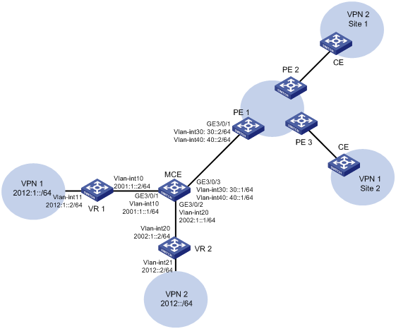
Configuration procedure
Assume that the system name of the MCE device is MCE, the system names of the edge devices of VPN 1 and VPN 2 are VR1 and VR2 respectively, and the system name of PE 1 is PE1.
1. Configure the VPN instances on the MCE and PE 1.
# On the MCE, configure VPN instances vpn1 and vpn2, and specify a RD and VPN targets for each VPN instance.
<MCE> system-view
[MCE] ip vpn-instance vpn1
[MCE-vpn-instance-vpn1] route-distinguisher 10:1
[MCE-vpn-instance-vpn1] vpn-target 10:1
[MCE-vpn-instance-vpn1] quit
[MCE] ip vpn-instance vpn2
[MCE-vpn-instance-vpn2] route-distinguisher 20:1
[MCE-vpn-instance-vpn2] vpn-target 20:1
[MCE-vpn-instance-vpn2] quit
# Create VLAN 10, add port GigabitEthernet 3/0/1 to VLAN 10, and create VLAN-interface 10.
[MCE] vlan 10
[MCE-vlan10] port GigabitEthernet 3/0/1
[MCE-vlan10] quit
# Bind VLAN-interface 10 with VPN instance vpn1, and configure an IPv6 address for the VLAN interface.
[MCE] interface vlan-interface 10
[MCE-Vlan-interface10] ip binding vpn-instance vpn1
[MCE-Vlan-interface10] ipv6 address 2001:1::1 64
[MCE-Vlan-interface10] quit
# Configure VLAN 20, add port GigabitEthernet 3/0/2 to VLAN 20, bind VLAN-interface 20 with VPN instance vpn2, and assign an IPv6 address to VLAN-interface 20.
[MCE] vlan 20
[MCE-vlan20] port GigabitEthernet 3/0/2
[MCE-vlan20] quit
[MCE] interface vlan-interface 20
[MCE-Vlan-interface20] ip binding vpn-instance vpn2
[MCE-Vlan-interface20] ipv6 address 2002:1::1 64
[MCE-Vlan-interface20] quit
# On PE 1, configure VPN instances vpn1 and vpn2, and specify an RD and VPN targets for each VPN instance.
<PE1> system-view
[PE1] ip vpn-instance vpn1
[PE1-vpn-instance-vpn1] route-distinguisher 30:1
[PE1-vpn-instance-vpn1] vpn-target 10:1
[PE1-vpn-instance-vpn1] quit
[PE1] ip vpn-instance vpn2
[PE1-vpn-instance-vpn2] route-distinguisher 40:1
[PE1-vpn-instance-vpn2] vpn-target 20:1
[PE1-vpn-instance-vpn2] quit
2. Configure routing between the MCE and VPN sites.
The MCE is connected to VPN 1 directly, and no routing protocol is enabled in VPN 1. Therefore, you can configure IPv6 static routes.
# On VR 1, assign IP address 2001:1::2/64 to the interface connected to the MCE and 2012:1::2/64 to the interface connected to VPN 1. Add ports to VLANs. (Details not shown)
# On VR 1, configure a default route with the next hop being 2001:1::1.
<VR1> system-view
[VR1] ipv6 route-static :: 0 2001:1::1
# On the MCE, configure an IPv6 static route to 2012:1::/64, specify the next hop as 2001:1::2, and bind the static route with VPN instance vpn1.
[MCE] ipv6 route-static vpn-instance vpn1 2012:1:: 64 vpn-instance vpn1 2001:1::2
# Run RIPng in VPN 2. Configure RIPng process 20 for VPN instance vpn2 on the MCE, so that the MCE can learn the routes of VPN 2 and add them to the routing table of VPN instance vpn2.
[MCE] ripng 20 vpn-instance vpn2
# Advertise subnet 2002:1::/64 through RIPng.
[MCE] interface vlan-interface 20
[MCE-Vlan-interface20] ripng 20 enable
[MCE-Vlan-interface20] quit
# On VR 2, assign IPv6 address 2002:1::2/64 to the interface connected to the MCE and 2012::2/64 to the interface connected to VPN 2. (Details not shown)
# Configure RIPng, and advertise subnets 2012::/64 and 2002:1::/64.
<VR2> system-view
[VR2] ripng 20
[VR2-ripng-20] quit
[VR2] interface vlan-interface 20
[VR2-Vlan-interface20] ripng 20 enable
[VR2-Vlan-interface20] quit
[VR2] interface vlan-interface 21
[VR2-Vlan-interface21] ripng 20 enable
[VR2-Vlan-interface21] quit
# On the MCE, display the routing tables of VPN instances vpn1 and vpn2.
[MCE] display ipv6 routing-table vpn-instance vpn1
Routing Table : vpn1
Destinations : 5 Routes : 5
Destination: ::1/128 Protocol : Direct
NextHop : ::1 Preference: 0
Interface : InLoop0 Cost : 0
Destination: 2001:1::/64 Protocol : Direct
NextHop : 2001:1::1 Preference: 0
Interface : Vlan10 Cost : 0
Destination: 2001:1::1/128 Protocol : Direct
NextHop : ::1 Preference: 0
Interface : InLoop0 Cost : 0
Destination: 2012:1::/64 Protocol : Static
NextHop : 2001:1::2 Preference: 60
Interface : Vlan10 Cost : 0
Destination: FE80::/10 Protocol : Direct
NextHop : :: Preference: 0
Interface : NULL0 Cost : 0
[MCE] display ipv6 routing-table vpn-instance vpn2
Routing Table : vpn2
Destinations : 5 Routes : 6
Destination: ::1/128 Protocol : Direct
NextHop : ::1 Preference: 0
Interface : InLoop0 Cost : 0
Destination: 2002:1::/64 Protocol : Direct
NextHop : 2002:1::1 Preference: 0
Interface : Vlan20 Cost : 0
Destination: 2002:1::1/128 Protocol : Direct
NextHop : ::1 Preference: 0
Interface : InLoop0 Cost : 0
Destination: 2012::/64 Protocol : RIPng
NextHop : FE80::200:5EFF:FE01:1C03 Preference: 100
Interface : Vlan20 Cost : 1
Destination: FE80::/10 Protocol : Direct
NextHop : :: Preference: 0
Interface : NULL0 Cost : 0
The output shows that the MCE has learned the private route of VPN 2. The MCE maintains the routes of VPN 1 and those of VPN 2 in two different routing tables. In this way, routes from different VPNs are separated.
3. Configure routing between the MCE and PE 1.
# On the MCE, configure the port connected to the PE 1 as a trunk port, and configure it to permit packets of VLAN 30 and VLAN 40 to pass with VLAN tags.
[MCE] interface GigabitEthernet 3/0/3
[MCE-GigabitEthernet3/0/3] port link-type trunk
[MCE-GigabitEthernet3/0/3] port trunk permit vlan 30 40
[MCE-GigabitEthernet3/0/3] quit
# On PE 1, configure the port connected to MCE as a trunk port, and configure it to permit packets of VLAN 30 and VLAN 40 to pass with VLAN tags.
<PE1> system-view
[PE1] interface GigabitEthernet 3/0/1
[PE1-GigabitEthernet3/0/1] port link-type trunk
[PE1-GigabitEthernet3/0/1] port trunk permit vlan 30 40
[PE1-GigabitEthernet3/0/1] quit
# On the MCE, create VLAN 30 and VLAN-interface 30, bind VLAN-interface 30 with VPN instance vpn1 and configure an IPv6 address for the VLAN-interface 30.
[MCE] vlan 30
[MCE-vlan30] quit
[MCE] interface vlan-interface 30
[MCE-Vlan-interface30] ip binding vpn-instance vpn1
[MCE-Vlan-interface30] ipv6 address 30::1 64
[MCE-Vlan-interface30] quit
# On the MCE, create VLAN 40 and VLAN-interface 40, bind VLAN-interface 40 with VPN instance vpn2 and configure an IPv6 address for the VLAN-interface 40.
[MCE] vlan 40
[MCE-vlan40] quit
[MCE] interface vlan-interface 40
[MCE-Vlan-interface40] ip binding vpn-instance vpn2
[MCE-Vlan-interface40] ipv6 address 40::1 64
[MCE-Vlan-interface40] quit
# On PE 1, create VLAN 30 and VLAN-interface 30, bind VLAN-interface 30 with VPN instance vpn1 and configure an IPv6 address for the VLAN-interface 30.
[PE1] vlan 30
[PE1-vlan30] quit
[PE1] interface vlan-interface 30
[PE1-Vlan-interface30] ip binding vpn-instance vpn1
[PE1-Vlan-interface30] ipv6 address 30::2 64
[PE1-Vlan-interface30] quit
# On PE 1, create VLAN 40 and VLAN-interface 40, bind VLAN-interface 40 with VPN instance vpn2 and configure an IPv6 address for the VLAN-interface 40.
[PE1] vlan 40
[PE1-vlan40] quit
[PE1] interface vlan-interface 40
[PE1-Vlan-interface40] ip binding vpn-instance vpn2
[PE1-Vlan-interface40] ipv6 address 40::2 64
[PE1-Vlan-interface40] quit
# Configure the IP address of the interface Loopback0 as 101.101.10.1 for the MCE and as 100.100.10.1 for PE 1. Specify the loopback interface address as the router ID for the MCE and PE 1. (Details not shown)
# Enable OSPFv3 process 10 on the MCE, bind the process to VPN instance vpn1, and redistribute the IPv6 static route of VPN 1.
[MCE] ospfv3 10 vpn-instance vpn1
[MCE-ospf-10] router-id 101.101.10.1
[MCE-ospf-10] import-route static
[MCE-ospf-10] quit
# Enable OSPFv3 on VLAN-interface 30.
[MCE] interface vlan-interface 30
[MCE-Vlan-interface30] ospfv3 10 area 0.0.0.0
[MCE-Vlan-interface30] quit
# On PE 1, enable OSPFv3 process 10 and bind the process to VPN instance vpn1.
[PE1] ospfv3 10 vpn-instance vpn1
[PE1-ospf-10] router-id 100.100.10.1
[PE1-ospf-10] quit
# Enable OSPFv3 on VLAN-interface 30.
[PE1] interface vlan-interface 30
[PE1-Vlan-interface30] ospfv3 10 area 0.0.0.0
[PE1-Vlan-interface30] quit
# On PE 1, display the routing table of VPN 1.
[PE1] display ipv6 routing-table vpn-instance vpn1
Routing Table : vpn1
Destinations : 5 Routes : 5
Destination: ::1/128 Protocol : Direct
NextHop : ::1 Preference: 0
Interface : InLoop0 Cost : 0
Destination: 30::/64 Protocol : Direct
NextHop : 30::2 Preference: 0
Interface : Vlan30 Cost : 0
Destination: 30::2/128 Protocol : Direct
NextHop : ::1 Preference: 0
Interface : InLoop0 Cost : 0
Destination: 2012:1::/64 Protocol : ISISv6
NextHop : FE80::200:5EFF:FE01:1C05 Preference: 15
Interface : Vlan10 Cost : 10
Destination: FE80::/10 Protocol : Direct
NextHop : :: Preference: 0
Interface : NULL0 Cost : 0
The output shows that PE 1 has learned the private route of VPN 1 through OSPFv3.
Take similar procedures to configure OSPFv3 process 20 between the MCE and PE 1 and redistribute VPN 2’s routes from RIPng process 20 into the OSPFv3 routing table of the MCE. The following output shows that PE 1 has learned the private route of VPN 2 through OSPFv3.
[PE1] display ipv6 routing-table vpn-instance vpn2
Routing Table : vpn2
Destinations : 5 Routes : 5
Destination: ::1/128 Protocol : Direct
NextHop : ::1 Preference: 0
Interface : InLoop0 Cost : 0
Destination: 40::/64 Protocol : Direct
NextHop : 40::2 Preference: 0
Interface : Vlan40 Cost : 0
Destination: 40::2/128 Protocol : Direct
NextHop : ::1 Preference: 0
Interface : InLoop0 Cost : 0
Destination: 2012::/64 Protocol : ISISv6
NextHop : FE80::200:5EFF:FE01:1C06 Preference: 15
Interface : Vlan20 Cost : 10
Destination: FE80::/10 Protocol : Direct
NextHop : :: Preference: 0
Interface : NULL0 Cost : 0
Now, the routing information of the two VPNs has been added into the routing tables on PE 1.