- Table of Contents
- Related Documents
-
| Title | Size | Download |
|---|---|---|
| 03-POS Interface Configuration | 123.1 KB |
Contents
Displaying and maintaining POS interfaces
POS interface configuration examples
Directly connecting switches through POS interfaces
Connecting switches through POS interfaces across frame relay
Troubleshooting POS interfaces
Overview
SONET
Synchronous Optical Network (SONET), a synchronous transmission system defined by the ANSI, is an international standard transmission protocol that adopts optical transmission.
SDH
Synchronous Digital Hierarchy (SDH), defined by the CCITT (today’s ITU-T), uses a SONET rate subset. SDH adopts synchronous multiplexing and allows for flexible mapping structure. Low-speed tributary signals can be added to or dropped from SDH signals without a large number of multiplexing/demultiplexing devices. This reduces signal attenuation and investment in network devices.
POS
Packet over SONET/SDH (POS) is a technology popular on WAN and MAN. It can support packet data such as IP packets.
POS maps length-variable packets directly to SONET synchronous payloads and uses the SONET physical layer transmission standard. It offers high-speed, reliable, and point-to-point data connectivity.
The POS interfaces on your switch support PPP, frame relay, and HDLC at the data link layer and IP at the network layer. Depending on the subcards of a POS interface, its transmission rate can be STM-1, STM-4, and STM-16, each four times the immediate lower level.
Configuration procedure
Before configuring the link layer and network layer protocols on a POS interface, you must configure its physical parameter settings.
|
Step |
Command |
Remarks |
|
1. Enter system view. |
system-view |
N/A |
|
2. Enter POS interface view. |
interface pos interface-number |
N/A |
|
3. Set the interface description. |
description text |
Optional. By default, the description of a POS interface is interface name Interface, for example, POS2/1/1 Interface. |
|
4. Set the clock mode. |
clock { master | slave } |
Optional. The default is slave. |
|
5. Set the CRC length. |
crc { 16 | 32 } |
Optional. The default is 32 bits. |
|
6. Set the loopback mode. |
loopback { local | remote } |
Optional. Loopback is disabled by default. Enable it only when special test is desired. |
|
7. Configure the overhead bytes. |
· flag c2 flag-value · flag { j0 | j1 } { sdh | sonet } flag-value |
Optional. · The default is hexadecimal 16 for C2. · By default, SDH framing applies. In SDH framing, the defaults are null for both J0 and J1. |
|
8. Set the framing format. |
frame-format { sdh | sonet } |
Optional. The default is SDH. |
|
9. Configure scrambling. |
scramble |
Optional. Enabled by default. |
|
10. Specify the link layer protocol. |
link-protocol { ppp | fr [ nonstandard | ietf ] | hdlc } |
Optional. The default is PPP. |
|
11. Set the interface MTU. |
mtu size |
Optional. The interface MTU (in bytes) ranges from 64 to 10240 and defaults to 1500. Currently, the maximum MTU you can configure for a POS interface is 10240 bytes, but the one that actually takes effect is 9216 bytes. |
|
12. Set the signal degrade (SD) or signal fail (SF) alarm threshold for the interface. |
threshold { sd | sf } value |
Optional. The SD alarm threshold defaults to 10e-6. The SF alarm threshold defaults to 10e-4. |
|
13. Set the protective action for alarms on the interface. |
alarm-detect { rdi | sd | sf } action link-down |
Optional. By default, no protective action for alarms is set on the interface. |
|
14. Set the rate of the POS interface. |
speed speed-value |
Optional. By default, the rate of a POS interface on a LSR1DTCP8L1 subcard is 155 Mbps. |
|
15. Set the statistics polling interval of the POS interface. |
flow-interval interval |
Optional. 300 seconds by default |
|
16. Set the physical state change suppression interval. |
link-delay msec milliseconds |
Optional. 1000 milliseconds by default. |
|
17. Restore the default settings. |
default |
Optional. |
|
18. Shut down the POS interface. |
shutdown |
Optional. By default, a POS interface is up. When you modify parameters on a POS interface, execute the shutdown command, and then the undo shutdown command to make your modifications take effect. |
|
|
NOTE: · The POS interface can work in the master clock mode only when the SRPU (or the main control board) is installed with a clock daughter card. · IPv6CP of PPP cannot get the peer IPv6 address through auto negotiation. Therefore, when a POS interface is used for IPv6 hardware forwarding, you need to configure static routes or routing protocols on it. |
Displaying and maintaining POS interfaces
|
Command |
Remarks |
|
|
Display information about one or all POS interfaces. |
display interface [ pos ] [ brief [ down ] ] [ | { begin | exclude | include } regular-expression ] display interface pos interface-number [ brief ] [ | { begin | exclude | include } regular-expression ] |
Available in any view |
|
Display IP-related configurations and statistics for one or all POS interfaces. |
display ip interface pos [ interface-number ] [ | { begin | exclude | include } regular-expression ] |
Available in any view |
|
Display IPv6-related configurations and statistics for one or all POS interfaces. |
display ipv6 interface pos [ interface-number | verbose ] [ | { begin | exclude | include } regular-expression ] |
Available in any view |
|
Clear the statistics on POS interfaces. |
reset counters interface [ pos [ interface-number ] ] |
Available in user view |
POS interface configuration examples
Directly connecting switches through POS interfaces
Network requirements
As shown in Figure 1,
· Use a pair of optical fibers (for receiving and sending data) to connect the POS interfaces on Switch A and Switch B.
· Enable PPP encapsulation on the interfaces.
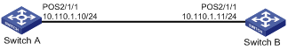
Configuration procedure
1. Configure Switch A:
# Configure interface POS 2/1/1, setting its physical parameters to defaults.
<SwitchA> system-view
[SwitchA] interface Pos 2/1/1
[SwitchA-Pos2/1/1] ip address 10.110.1.10 255.255.255.0
[SwitchA-Pos2/1/1] link-protocol ppp
[SwitchA-Pos2/1/1] mtu 1500
[SwitchA-Pos2/1/1] shutdown
[SwitchA-Pos2/1/1] undo shutdown
2. Configure Switch B:
# Configure interface POS 2/1/1.
<SwitchB> system-view
[SwitchB] interface Pos 2/1/1
# Set the clock mode to master and other physical parameters to defaults.
[SwitchB-Pos2/1/1] clock master
[SwitchB-Pos2/1/1] ip address 10.110.1.11 255.255.255.0
[SwitchB-Pos2/1/1] link-protocol ppp
[SwitchB-Pos2/1/1] mtu 1500
[SwitchB-Pos2/1/1] shutdown
[SwitchB-Pos2/1/1] undo shutdown
You can check the connectivity between the POS interfaces by using the display interface pos command and test network connectivity by using the ping command.
Connecting switches through POS interfaces across frame relay
Network requirements
As shown in Figure 2, connect switches to a public frame relay network through POS interfaces. The switches are premise equipment that work as DTE side of frame relay.
Switch A uses frame relay sub-interfaces to connect Switch B and Switch C in different network segments.
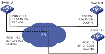
Configuration procedure
1. Configure Switch A:
# Configure POS interface 3/1/1.
<SwitchA> system-view
[SwitchA] interface Pos 3/1/1
[SwitchA-Pos3/1/1] clock slave
# Configure frame relay encapsulation on the interface.
[SwitchA-Pos3/1/1] link-protocol fr
[SwitchA-Pos3/1/1] fr interface-type dte
[SwitchA-Pos3/1/1] quit
# Create sub-interface 1 on the interface.
[SwitchA] interface Pos 3/1/1.1
[SwitchA-Pos3/1/1.1] ip address 10.10.10.1 255.255.255.0
[SwitchA-Pos3/1/1.1] fr dlci 50
[SwitchA-Pos3/1/1.1] fr map ip 10.10.10.2 50
[SwitchA-Pos3/1/1.1] mtu 1500
[SwitchA-Pos3/1/1.1] quit
# Create sub-interface 2 on the interface.
[SwitchA] interface Pos 3/1/1.2
[SwitchA-Pos3/1/1.2] ip address 20.10.10.1 255.255.255.0
[SwitchA-Pos3/1/1.2] fr dlci 60
[SwitchA-Pos3/1/1.2] fr map ip 20.10.10.2 60
[SwitchA-Pos3/1/1.2] mtu 1500
[SwitchA-Pos3/1/1.2] quit
2. Configure Switch B:
# Configure interface POS 3/1/1.
[SwitchB] interface Pos 3/1/1
[SwitchB-Pos3/1/1] clock slave
# Configure frame relay encapsulation on the interface.
[SwitchB-Pos3/1/1] link-protocol fr
[SwitchB-Pos3/1/1] fr interface-type dte
[SwitchB-Pos3/1/1] ip address 10.10.10.2 255.255.255.0
[SwitchB-Pos3/1/1] fr dlci 70
[SwitchB-Pos3/1/1] fr map ip 10.10.10.1 70
[SwitchB-Pos3/1/1] mtu 1500
Follow the same way to configure Switch C.
Check interface connectivity with the display interface pos command and test network connectivity with the ping command.
Troubleshooting POS interfaces
Symptom 1
The physical state of a POS interface is down.
Solution
· Check that the transmitting and receiving optical fibers are correctly connected to the POS interface. If you connect the two ends of an optical fiber to the transmitting end and the receiving end of the same POS interface, you can see the message “loopback detected” on the screen when executing the display interface command even if you have not enabled loopback.
· If the two switches are directly connected (back to back), check that the POS interfaces use different clock modes.
Symptom 2
The physical layer is up but the link is down.
Solution
Check that:
· The settings of clock, scrambling and other physical parameters are consistent on the two connected POS interfaces.
· The same link layer protocol is configured on two sides.
· Both ends are assigned IP addresses.
Symptom 3
A great amount of IP packets are dropped.
Solution
Check that:
· The correct clock mode is configured on the POS interface. If not, enormous amount of CRC errors will be generated.
· The Maximum transmission unit (MTU) configuration is matched.