- Table of Contents
- Related Documents
-
| Title | Size | Download |
|---|---|---|
| 02-Ethernet Interface Configuration | 233.98 KB |
Contents
Configuring Ethernet interfaces
Configuring general Ethernet interfaces and subinterfaces
Ethernet interface numbering conventions
Ethernet interface configuration task list
Configuring the operating mode for a 10-GE interface
Switching the link mode of an Ethernet interface between Layer 2 and Layer 3
Configuring basic settings of an Ethernet interface or subinterface
Bringing up Ethernet interfaces and subinterfaces
Configuring flow control on an Ethernet interface
Setting the statistics polling interval on an Ethernet interface
Configuring physical state change suppression on an Ethernet interface
Configuring loopback testing on an Ethernet interface
Configuring Layer 2 Ethernet interfaces
Layer 2 Ethernet interface configuration task list
Configuring a manual port group
Setting speed options for auto negotiation on an Ethernet interface
Configuring storm suppression for an Ethernet interface
Configuring jumbo frame support
Setting the MDI mode of an Ethernet interface
Forcibly bringing up an Ethernet interface
Configuring the connection mode of an Ethernet interface
Configuring Layer 3 Ethernet interface and subinterfaces
Setting the MTU for an Ethernet interface or subinterface
Displaying and maintaining Ethernet interfaces
|
|
NOTE: · The switch does not support Layer 3 Ethernet interfaces, Layer 3 Ethernet subinterfaces, Layer 3 aggregate interfaces, and Layer 3 aggregate subinterfaces when it works in standard mode. For more information about system working modes, see Fundamentals Configuration Guide. · The switch operates in IRF or standalone (the default) mode. For more information about the IRF mode, see IRF Configuration Guide. · For more information about the models of the Ethernet interface cards, see the installation guide. |
Ethernet is the most widespread wired LAN technology due to its flexibility, simplicity, and easy implementation. Your device supports the following types of Ethernet interfaces:
· Layer 2 Ethernet interfaces—They are physical interfaces operating on the data link layer for Layer 2 packet forwarding. They can only forward packets carrying source and destination IP addresses that belong to the same network segment.
· Layer 3 Ethernet interfaces—They are physical interfaces operating on the network layer for Layer 3 packet forwarding, and forward packets carrying source and destination IP addresses that belong to different network segments. You can assign an IP address to a Layer 3 Ethernet interface.
· Layer 2-Layer 3 Ethernet interfaces—They are physical interfaces that can operate on both the data link layer and the network layer. When operating on the data link layer, a Layer 2-Layer 3 Ethernet interface acts as a Layer 2 Ethernet interface. When operating on the network layer, a Layer 2-Layer 3 Ethernet interface acts as a Layer 3 Ethernet interface.
· Layer 3 Ethernet subinterfaces—They are logical interfaces operating on the network layer. You can assign an IP address to a Layer 3 Ethernet subinterface. By creating subinterfaces on a Layer 3 Ethernet interface, you can enable the interface to carry packets for multiple VLANs, which provides great networking flexibility.
Configuring general Ethernet interfaces and subinterfaces
|
|
NOTE: By default, Ethernet interfaces, VLAN interfaces, and aggregate interfaces are in DOWN state. Before configuring these interfaces, use the undo shutdown command to bring them up. |
Ethernet interface numbering conventions
When the switch operates in standalone mode, an Ethernet interface is numbered in the format of interface type A/B/C, where:
· A is the slot number of the card where the Ethernet interface resides.
· B is the number of the sub-card where the Ethernet interface resides.
If the card does not have any sub-card, B is fixed at 0.
· C is the interface number.
When the switch operates in IRF mode, an Ethernet interface is numbered in the format of interface type A/B/C/D, where:
· A is the ID of the IRF member switch where the Ethernet interface resides.
A can be 1 or 2.
· B is the slot number of the card where the Ethernet interface resides.
· C is the number of the sub-card where the Ethernet interface resides.
If the card does not have any sub-card, C is fixed at 0.
· D is the interface number.
Ethernet interface configuration task list
Complete the following tasks to configure an Ethernet interface:
|
Task |
Remarks |
|
Optional |
|
|
Optional |
|
|
Switching the link mode of an Ethernet interface between Layer 2 and Layer 3 |
Optional |
|
Configuring basic settings of an Ethernet interface or subinterface |
Optional |
|
Optional |
|
|
Optional |
|
|
Setting the statistics polling interval on an Ethernet interface |
Optional |
|
Configuring physical state change suppression on an Ethernet interface |
Optional |
|
Optional |
Configuring a combo interface
Introduction to Combo interfaces
A Combo interface is a logical interface that comprises one optical (fiber) port and one electrical (copper) port. The two ports share one forwarding interface, so they cannot work simultaneously. When you enable either port, the other port is automatically disabled.
The fiber and copper ports of a Combo interface share one interface view, in which you activate the fiber or copper port, and configure other port attributes, such as the interface rate and duplex mode.
Configuration prerequisites
Before configuring a Combo interface:
· Determine the combo interfaces on your device by checking the product specifications and identify the two physical interfaces that compose each combo interface.
· Identify which port of the interface is active by using the display interface command. If the output includes “Media type is twisted pair, Port hardware type is 1000_BASE_T”, the copper port is active. If the output includes “Media type is not sure, Port hardware type is No connector”, the fiber interface is active.
Changing the active port of a Combo interface
To change the active port of a Combo interface:
|
Step |
Command |
Remarks |
|
1. Enter system view. |
system-view |
N/A |
|
2. Enter Ethernet interface view. |
interface interface-type interface-number |
N/A |
|
3. Activate the copper or fiber port of the Combo interface. |
combo enable { copper | fiber } |
Optional. By default, the copper port is active. |
|
|
CAUTION: · When you activate the fiber port of a Combo interface, the switch removes the current port settings (such as rate, duplex mode, and MDI), if the fiber port does not support them. · You cannot bind a Combo interface with an IRF port. For more information about IRF, see IRF Configuration Guide. |
Configuring the operating mode for a 10-GE interface
Introduction to the operating modes
A ten-GigabitEthernet (10-GE) interface works in LAN or WAN mode:
· In LAN mode, the 10-GE interface transmits Ethernet packets, providing access to an Ethernet network.
· In WAN mode, the 10-GE interface transmits synchronous digital hierarchy (SDH) packets, providing access to an SDH network. In this mode, the interface supports only point-to-point connections.
|
|
NOTE: A 10-GE interface operating in WAN mode cannot communicate with a 10G Packet over SDH (POS) interface. Both kinds of interfaces encapsulate packets as SDH frames, but the SDH frames have incompatible formats. |
Introduction to the J0 and J1 overhead bytes
SDH frames have diversified overhead bytes, which perform the operation and maintenance functions such as hierarchical management of the transport network. J0 and J1 are used to provide internetworking support between different countries, regions, or network devices of different manufacturers.
The regenerator section trace byte J0 is usually set to a section access point identifier. The sending end stays connected with the receiving end by sending this byte repeatedly.
The path trace byte J1, usually set to a high-order path access point identifier, functions in a similar to keep the connection with the receiving end of the path.
To ensure smooth communication, the J0 and J1 bytes should be matched at, respectively, the sending and receiving ends.
Configuration procedure
To configure the operating mode for a 10-GE interface:
|
Step |
Command |
Remarks |
|
1. Enter system view. |
system-view |
N/A |
|
2. Enter ten-GigabitEthernet interface view. |
interface ten-gigabitethernet interface-number |
N/A |
|
3. Set the 10-GE interface to operate in LAN or WAN mode. |
port-mode { lan | wan } |
Optional. By default, a 10-GE interface operates in LAN mode. |
|
4. Configure the J0 or J1 byte when the 10-GE interface is operating in WAN mode.. |
flag { j0 | j1 } sdh value |
Optional. By default, the value of the J0 and J1 bytes is 0. |
|
5. Configure the SD or SF threshold when the 10-GE interface is operating in WAN mode. |
threshold { sd | sf } value |
Optional. By default, the value of the SD threshold is 10e-6 (the value argument is 6),the value of the SF threshold is 10e-4 (the value argument is 4). |
|
6. Set the protective action for alarms when the 10 GE interface is operating in WAN mode. |
alarm-detect { rdi | sd | sf } action link-down |
Optional. By default, no protective action for alarms is configured. |
|
|
NOTE: The flag, threshold, and alarm-detect commands are available only when the 10-GE interface is operating in WAN mode. |
Switching the link mode of an Ethernet interface between Layer 2 and Layer 3
Depending on the layer at which the switch processes received data packets, Ethernet interfaces on the switch may operate either as Layer 2 Ethernet interfaces (in bridge mode), or as Layer 3 Ethernet interfaces (in route mode). You can set the link mode of an Ethernet interface to bridge or route.
To change the link mode of an Ethernet interface:
|
Step |
Command |
Remarks |
|
1. Enter system view. |
system-view |
N/A |
|
2. Change the link mode of Ethernet interfaces. |
·
(Approach I) In system view: · (Approach II) In Ethernet interface view: a. interface interface-type interface-number b. port link-mode { bridge | route } |
Use either approach. By default, Ethernet interfaces operate in bridge mode. |
|
|
CAUTION: · The switch supports this command when the working mode is not the standard mode. The switch works in standard mode by default. For more information about system working modes, see Fundamentals Configuration Guide. · After you change the operating mode of an Ethernet interface, all the settings of the Ethernet interface will restore to the default configuration in the new mode. · The Ethernet interface link mode can be configured in either the system view or the Ethernet view and when the two link modes are different, the one configured last takes effect. · You cannot configure Layer 3 Ethernet interfaces as physical IRF ports. |
Configuring basic settings of an Ethernet interface or subinterface
Configuring an Ethernet interface
You can set an Ethernet interface to operate in one of the following duplex modes:
· Full-duplex mode (full)—Interfaces operating in this mode can send and receive packets simultaneously.
· Half-duplex mode (half)—Interfaces operating in this mode can either send or receive packets at a given time.
· Auto-negotiation mode (auto)—Interfaces operating in this mode determine a duplex mode through auto-negotiation.
You can set the speed of an Ethernet interface or enable it to automatically negotiate a speed with its peer. For auto-negotiation, you can also set speed options. The two ends can pick a speed only from the options. For a 100-Mbps or 1000-Mbps Layer 2 Ethernet interface, you can also set speed options for auto negotiation. The two ends can pick a speed only from the available options. For more information, see “Setting speed options for auto negotiation on an Ethernet interface.”
To configure basic Ethernet interface settings:
|
Step |
Command |
Remarks |
|
1. Enter system view. |
system-view |
N/A |
|
2. Enter Ethernet interface view. |
interface interface-type interface-number |
N/A |
|
3. Set the descriptive information for the Ethernet interface. |
description text |
Optional. By default, the descriptive information is “interface name + Interface”. |
|
4. Set the duplex mode. |
duplex { auto | full | half } |
Optional. The default setting is auto. A fiber port does not support half keyword. 10-GE interfaces do not support this command. |
|
5. Set the transmission rate. |
speed { 10 | 100 | 1000 | auto } |
Optional. The default setting is auto. |
|
6. Restore the default settings. |
default |
Optional. |
|
7. Set the intended bandwidth. |
bandwidth bandwidth-value |
Optional. |
|
|
CAUTION: Because a 1000-Mbps interface cannot work in half duplex mode, you cannot use the duplex half command together with the following commands: speed 1000 and speed auto 1000 [ 10 | 100 ] *. |
Configuring an Ethernet subinterface
To configure an Ethernet subinterface:
|
Step |
Command |
Remarks |
|
1. Enter system view. |
system-view |
N/A |
|
2. Enter Ethernet interface view. |
interface interface-type interface-number |
N/A |
|
3. Configure the interface to operate in Layer 3 mode. |
port link-mode route |
By default, an Ethernet interface operates in Layer 2 mode. |
|
4. Return to system view. |
quit |
N/A |
|
5. Create an Ethernet subinterface. |
interface interface-type interface-number.subnumber |
This command also leads you to Ethernet subinterface view. |
|
6. Set the interface description. |
description text |
Optional. By default, the description of an interface is in the format of interface-name Interface. For example, GigabitEthernet3/0/2.1 Interface. |
|
7. Restore the default settings. |
default |
Optional. |
|
|
NOTE: · You can configure IP-related settings on an Ethernet subinterface. For more information, see Layer 3—IP Services Configuration Guide. · For the local and remote Ethernet subinterfaces to transmit traffic correctly, configure them with the same subinterface number and VLAN ID. |
Bringing up Ethernet interfaces and subinterfaces
You can use the commands in this section to bring up a single Ethernet interface in Ethernet interface view, or to bring up multiple Ethernet interfaces in port group view.
To bring up Ethernet interfaces:
|
Step |
Command |
Remarks |
|
1. Enter system view. |
system-view |
N/A |
|
2. Enter Ethernet interface or subinterface view, or port group view. |
·
Enter Ethernet interface view: · Enter Ethernet subinterface view: ·
Enter port group view: |
Use any command. To shut down an Ethernet interface or subinterface, enter Ethernet interface or subinterface view. To shut down all Ethernet interfaces in a port group, enter port group view. You can enter Ethernet subinterface view only when the Ethernet interface operates in Layer 3 mode. |
|
3. Bring up Ethernet interfaces. |
undo shutdown |
Optional. By default, Ethernet interfaces are in DOWN state. |
Configuring flow control on an Ethernet interface
You can avoid packet drops on a link by enabling flow control at both ends of the link. When traffic congestion occurs at the receiving end, the receiving end sends a Pause frame to notify the sending end to suspend sending packets.
To enable flow control on an Ethernet interface:
|
Step |
Command |
Remarks |
|
1. Enter system view. |
system-view |
N/A |
|
2. Enter Ethernet interface view. |
interface interface-type interface-number |
N/A |
|
3. Enable flow control. |
flow-control |
By default, flow control is disabled. |
Setting the statistics polling interval on an Ethernet interface
To set the statistics polling interval on an Ethernet interface:
|
Step |
Command |
Remarks |
|
1. Enter system view. |
system-view |
N/A |
|
2. Enter Ethernet interface view. |
interface interface-type interface-number |
N/A |
|
3. Set the statistics polling interval. |
flow-interval interval |
The default interface statistics polling interval is 300 seconds. |
To display the interface statistics collected in the last polling interval, use the display interface command.
Configuring physical state change suppression on an Ethernet interface
The physical link state of an Ethernet interface is either up or down. Each time the physical link of a port goes up or comes down, the system immediately reports the change to the upper-layer protocol modules (such as routing and forwarding modules) for packet transmission, and automatically generates traps and logs, informing the user to take corresponding actions.
To prevent frequent physical link flapping from affecting system performance, configure physical state change suppression to suppress the reporting of physical link state changes. The system reports physical layer changes only when the suppression interval expires. If you want to obtain physical layer changes within the suppression interval, enable the damping function with the link-delay enable trap updown command on the port.
To configure physical state change suppression on an Ethernet interface:
|
Step |
Command |
Remarks |
|
1. Enter system view. |
system-view |
N/A |
|
2. Enter Ethernet interface view. |
interface interface-type interface-number |
N/A |
|
3. Configure the physical state change suppression interval. |
link-delay delay-time |
The default setting is 1 second. |
|
4. Enable the damping function on the port. |
link-delay enable trap updown |
Optional. By default, the damping function is disabled on a port. |
Configuring loopback testing on an Ethernet interface
If an Ethernet interface does not work normally, you can enable loopback testing on it to identify the problem.
If an Ethernet interface is in a loopback test, it does not forward data traffic.
To enable loopback testing on an Ethernet interface:
|
Step |
Command |
Remarks |
|
1. Enter system view. |
system-view |
N/A |
|
2. Enter Ethernet interface view. |
interface interface-type interface-number |
N/A |
|
3. Bring up the interface. |
undo shutdown |
N/A |
|
4. Enable loopback testing. |
loopback { external | internal } |
Optional. By default, loopback testing is disabled. |
|
|
NOTE: · The loopback external configuration command is available only on the Ethernet interface that supports 10-G XFP transceiver modules. · Internal loopback testing can be enabled on interfaces in DOWN state, but not on those administratively shut down. · The speed, duplex, mdi, combo enable, and shutdown commands are not available during a loopback testing. · During loopback testing, an Ethernet interface works at its highest speed in full duplex mode. When you disable loopback testing, the rate and duplex mode of the interface restore. |
Configuring Layer 2 Ethernet interfaces
Layer 2 Ethernet interface configuration task list
Complete these tasks to configure Layer 2 Ethernet interfaces, which operate in bridge mode:
|
Task |
Remarks |
|
Optional Applicable to Layer 2 Ethernet interfaces |
|
|
Setting speed options for auto negotiation on an Ethernet interface |
Optional Applicable to 100-Mbps or 1000-Mbps Layer 2 Ethernet interfaces |
|
Optional Applicable to Layer 2 Ethernet interfaces |
|
|
Optional Applicable to Layer 2 Ethernet interfaces |
|
|
Optional Applicable to Layer 2 Ethernet interfaces |
|
|
Optional Applicable to Layer 2 Ethernet interfaces |
|
|
Optional Applicable to Layer 2 Ethernet interfaces |
Configuring a manual port group
Some interfaces on your device may use the same set of settings. To configure these interfaces in bulk rather than one by one, you can assign them to a port group.
You create port groups manually. All settings made for a port group apply to all the member ports of the group. For example, you can configure a traffic suppression threshold (see Configuring storm suppression for an Ethernet interface) for multiple interfaces in bulk by assigning these interfaces to a port group.
Even though the settings are made on the port group, they are saved on an interface basis rather than on a port group basis. You can only view the settings in the view of each interface by use the display current-configuration or display this command.
To configure a manual port group:
|
Step |
Command |
Remarks |
|
1. Enter system view. |
system-view |
N/A |
|
2. Create a manual port group and enter manual port group view. |
port-group manual port-group-name |
By default, no manual port group is created. |
|
3. Assign Ethernet interfaces to the manual port group. |
group-member interface-list |
By default, no Ethernet interface is in any manual port group. |
Setting speed options for auto negotiation on an Ethernet interface
Speed auto negotiation enables an Ethernet interface to negotiate with its peer for the highest speed supported by both ends by default. If the highest speed is not desirable, you can narrow down the speed option list for negotiation.
Figure 1 Speed auto negotiation application scenario
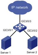
As shown in Figure 1, the network adapters of Server 1 and Server 2 both operate at 1000 Mbps, and the uplink port of the switch, GigabitEthernet 3/0/3, also operates at 1000 Mbps. If no speed options are set on the switch, the result of speed negotiation between GigabitEthernet 3/0/1 and GigabitEthernet 3/0/2 and the servers will be 1000 Mbps. As a result, congestion may occur on GigabitEthernet 3/0/3.
To avoid congestion on GigabitEthernet 3/0/3, configure 100 Mbps as the only option available for speed negotiation on GigabitEthernet 3/0/1 and GigabitEthernet 3/0/2. In this way, the transmission rate on both GigabitEthernet 3/0/1 and GigabitEthernet 3/0/2 is limited to 100 Mbps.
To set speed options for auto negotiation on an Ethernet interface:
|
Step |
Command |
Remarks |
|
1. Enter system view. |
system-view |
N/A |
|
2. Enter Ethernet interface view. |
interface interface-type interface-number |
N/A |
|
3. Set speed options for auto negotiation. |
speed auto { 10 | 100 | 1000 } * |
Optional. By default, no speed options for auto negotiation are set. |
|
|
NOTE: · This function is available only for 100-Mbps and 1000-Mbps Layer 2 Ethernet interfaces that support speed auto negotiation. For a Combo interface, only the copper port supports this function. · The speed and speed auto commands supersede each other, and whichever is configured last takes effect. |
Configuring storm suppression for an Ethernet interface
You can suppress the broadcast, unknown multicast, and unknown unicast traffic passing through an Ethernet interface by setting a traffic threshold. When the traffic threshold is exceeded, the interface drops excessive packets.
To configure the storm suppression function for an Ethernet interface:
|
Step |
Command |
Remarks |
|
1. Enter system view. |
system-view |
N/A |
|
2. Enter Ethernet interface view or port group view. |
·
Enter Ethernet interface view: ·
Enter port group view: |
Use either command. Configurations made in interface view take effect on the current interface only. Configurations made in port group view take effect on all interfaces in the group. |
|
3. Configure broadcast suppression. |
broadcast-suppression { pps max-pps | kbps max-kbps } |
Optional. By default, all broadcast traffic can pass through an Ethernet interface. |
|
4. Configure unknown multicast suppression. |
multicast-suppression { kbps max-kbps | pps max-pps } |
Optional. By default, all unknown multicast traffic can pass through an Ethernet interface. |
|
5. Configure unknown unicast suppression. |
unicast-suppression { kbps max-kbps | pps max-pps } |
Optional. By default, all unknown unicast traffic can pass through an Ethernet interface. |
|
|
CAUTION: · On an interface card, the thresholds for different types of traffic must use the same unit of measurement. For example, if you have configured the broadcast-suppression kbps max-kbps command for one interface on an interface card, you cannot configure the multicast-suppression pps max-pps command for any other interface on the interface card. · On an interface, you can configure only one traffic threshold. For example, if you have configured the broadcast-suppression kbps 100 command on an interface, you cannot configure a command like unicast-suppression kbps 200 or multicast-suppression kbps 200 on it. |
Configuring jumbo frame support
An Ethernet interface may receive some frames larger than the standard Ethernet frame size (called jumbo frames) during high-throughput data exchanges such as file transfers. Usually, an Ethernet interface discards jumbo frames. With jumbo frame support enabled, the interface can process frames larger than the standard Ethernet frame size yet within the specified range.
To configure jumbo frame support on Ethernet interfaces:
|
Step |
Command |
Remarks |
|
1. Enter system view. |
system-view |
N/A |
|
2. Enter Ethernet interface view or port group view. |
·
Enter Ethernet interface view: ·
Enter port group view: |
Use either command. Configurations made in interface view take effect on the current interface only. Configurations made in port group view take effect on all interfaces in the group. |
|
3. Configure jumbo frame support. |
jumboframe enable [ value ] |
Optional. By default, the switch allows 9216-byte jumbo frames to pass through Ethernet interfaces. |
Setting the MDI mode of an Ethernet interface
|
|
NOTE: Fiber ports do not support the MDI mode setting. |
You can use both crossover and straight-through Ethernet cables to connect copper Ethernet interfaces. To accommodate these two types of cables, a copper Ethernet interface can operate in one of the following Medium Dependent Interface (MDI) modes:
· Across mode
· Normal mode
· Auto mode
A copper Ethernet interface uses an RJ-45 connector, which comprises eight pins, each playing a dedicated role. For example, pins 1 and 2 transmit signals, and pins 3 and 6 receive signals. The pin role varies by the following MDI modes:
· In normal mode, pins 1 and 2 are transmit pins, and pins 3 and 6 are receive pins.
· In across mode, pins 1 and 2 are receive pins, and pins 3 and 6 are transmit pins.
· In auto mode, the interface negotiates pin roles with its peer.
To enable the interface to communicate with its peer, make sure that its transmit pins are connected to the remote receive pins. If the interface can detect the connection cable type, set the interface in auto MDI mode. If not, set its MDI mode using the following guidelines:
· When a straight-through cable is used, set the interface to work in the MDI mode different than its peer.
· When a crossover cable is used, set the interface to work in the same MDI mode as its peer, or set either end to work in auto mode.
To configure the MDI mode of an Ethernet Interface:
|
Step |
Command |
Remarks |
|
system-view |
N/A |
|
|
2. Enter Ethernet interface view. |
interface interface-type interface-number |
N/A |
|
3. Configure the MDI mode of the Ethernet interface. |
mdi { across | auto | normal } |
Optional. The default is auto. The switch decides the role of the pins (to send packets or receive packets) through auto negotiation. |
Forcibly bringing up an Ethernet interface
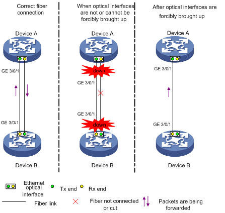
As shown in Figure 2, a fiber port uses separate wires for transmitting and receiving packets. The physical state is up only when both transmit and receive fibers are present. If one of the fibers is disconnected, the fiber port does not work.
To enable a fiber port to perform one-way forwarding when only one fiber is present, you can use the port up-mode command. This command brings up an Ethernet fiber port by force, even when no fiber links or transceiver modules are present. If one fiber link is present and up, the fiber port can forward packets over the link unidirectionally.
Figure 2 Forcibly bring up an Ethernet interface
To forcibly bring up an Ethernet Interface:
|
Step |
Command |
Remarks |
|
1. Enter Ethernet interface view. |
interface interface-type interface-number |
N/A |
|
2. Forcibly bring up the Ethernet interface. |
port up-mode |
Optional. By default, the Ethernet interface is not forcibly brought up. To disable the function, use undo port up-mode command. |
|
|
NOTE: · Only the general GE fiber port and the 10-GE fiber port operating in LAN mode can be forcibly brought up. Copper ports and combo interfaces do not support this function. · The port up-mode command cannot be used together with any of the shutdown, speed, duplex, or loopback commands. · When a fiber-to-copper media converter, 100/1000-Mbps transceiver module, or 100-Mbps transceiver module is inserted into a fiber GE port forcibly brought up, traffic cannot be forwarded properly; when a copper transceiver module is inserted into the 10GE fiber port forcibly brought up, the traffic cannot be forwarded properly. To enable such an interface to forward traffic properly, use the undo port up-mode command on the interface. |
Configuring the connection mode of an Ethernet interface
When deploying the switch in an OAA networking environment, to ensure normal communication between the switch and the OAP card, you must set the connection mode of the interface connecting the switch and the card to extended. For more information about OAP, see OAA Configuration Guide.
To configure the connection mode of an Ethernet interface:
|
Step |
Command |
Remarks |
|
1. Enter system view. |
system-view |
N/A |
|
2. Enter Ethernet interface view. |
interface interface-type interface-number |
Make sure that you specify the interface that connects the switch to the OAP card. |
|
3. Set the connection mode of the Ethernet interface. |
port connection-mode { extend | normal } |
The default setting is normal. |
Configuring Layer 3 Ethernet interface and subinterfaces
Setting the MTU for an Ethernet interface or subinterface
The value of Maximum Transmission Unit (MTU) affects the fragmentation and re-assembly of IP packets.
To set the MTU for an Ethernet interface or subinterface:
|
Step |
Command |
Remarks |
|
1. Enter system view. |
system-view |
N/A |
|
2. Enter Ethernet interface or subinterface view. |
interface interface-type { interface-number | interface-number.subnumber } |
N/A |
|
3. Set the MTU. |
mtu size |
Optional. The default setting is 1500 bytes. |
Displaying and maintaining Ethernet interfaces
|
Task |
Command |
Remarks |
|
Display Ethernet interface information. |
display interface [ interface-type ] [ brief [ down ] ] [ | { begin | exclude | include } regular-expression ] display interface interface-type interface-number [ brief ] [ | { begin | exclude | include } regular-expression ] |
Available in any view |
|
Display information about a manual port group or all manual port groups. |
display port-group manual [ all | name port-group-name ] [ | { begin | exclude | include } regular-expression ] |
Available in any view |
|
Display traffic statistics for interfaces. |
display counters { inbound | outbound } interface [ interface-type ] [ | { begin | exclude | include } regular-expression ] |
Available in any view |
|
Display traffic rate statistics over the last sampling interval for interfaces. |
display counters rate { inbound | outbound } interface [ interface-type ] [ | { begin | exclude | include } regular-expression ] |
Available in any view |
|
Clear statistics for Ethernet interfaces. |
reset counters interface [ interface-type [ interface-number ] ] |
Available in user view |