| Title | Size | Downloads |
|---|---|---|
| H3C S3100 Series Ethernet Switches Operation Manual-Release 22XX Series(V1.00)-VLAN Mapping Operation.pdf | 306.15 KB |
- Table of Contents
- Related Documents
-
| Title | Size | Download |
|---|---|---|
| 37-VLAN Mapping Operation | 306.15 KB |
Implementation and Application of One-to-one VLAN mapping
Implementation and Application of Many-to-One VLAN Mapping
Configuring the DHCP Option 82 for Many-to-One VLAN Mapping
Configuring One-to-one VLAN Mapping
One-to-one VLAN Mapping Configuration Task List
Configuring a Global One-to-One VLAN Mapping Rule
Configuring a Port-Level One-to-One VLAN Mapping Rule
Configuring Many-to-One VLAN Mapping
Configuring a Many-to-One VLAN Mapping Rule
Configuring DHCP Snooping Option 82 to Carry the Original VLAN Information
One-to-One VLAN Mapping Configuration Example
Many-to-One VLAN Mapping Configuration Example
![]()
The VLAN mapping feature is applicable to only the S3100-EI series among the S3100 series.
VLAN Mapping Overview
VLAN mapping replaces the original VLAN tag of a packet with a new one, so that the packet can be processed and forwarded according to the new VLAN tag. Types of VLAN mapping include:
l One-to-one VLAN mapping
l Many-to-one VLAN mapping
In a campus network with a large number of terminal users who need VLAN for segregation, VLAN mapping segregates same-type traffic streams by user, or aggregates the traffic streams from multiple VLANs of the same user. The following part introduces the effects of the two VLAN mapping types.
Implementation and Application of One-to-one VLAN mapping
One-to-one VLAN mapping maps traffic from one VLAN to another VLAN for transmission. On an S3100-EI switch, you can configure a global one-to-one VLAN mapping rule or port-level one-to-one VLAN mapping rules. With one-to-one VLAN mapping enabled on a port and a one-to-one VLAN mapping rule defined globally or on the port, the port can replace the original VLAN tag of uplink traffic and restore the original VLAN of downlink traffic according to the mapping rule.
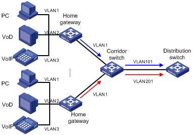
A typical application scenario of one-to-one VLAN mapping is as shown in Figure 1-1:
Figure 1-1 Application scenario of one-to-one VLAN mapping

As shown in Figure 1-1, each user in the community has multiple applications. The VLAN technology is used on the home gateway to distinguish traffic types. Because each home gateway has the same configuration, the same type of traffic from different users is transmitted within the same VLAN. As a result, the upper-layer device (such as the distribution switch) cannot identify the users of traffic streams.
To address this problem, configure one-to-one VLAN mapping on the corridor switch to map the same type of traffic received on different ports to different VLANs, so that the upper-layer device can identify the user of a traffic stream by VLAN. After one-to-one VLAN mapping is configured, the network is as shown in Figure 1-2:
Figure 1-2 After one-to-one VLAN mapping
Implementation and Application of Many-to-One VLAN Mapping
Many-to-one VLAN mapping maps traffic from two or more VLANs to the same VLAN for transmission.
Many-to-one VLAN mapping can map uplink traffic streams from multiple original VLANs to the same target VLAN, and can correctly restore the original VLANs for downlink traffic streams.
l In the uplink direction, you can configure a mapping rule to map multiple original VLANs to the same target VLAN. In addition, upon receiving an uplink packet from an original VLAN, the device records the source MAC address of the packet in the MAC address table of the original VLAN.
l In the downlink direction, upon receiving a downlink packet, the device searches for the destination MAC address of the packet in the MAC address tables of all original VLANs. If a match is found in an original VLAN, the device replaces the VLAN tag of the downlink packet with the original VLAN tag.
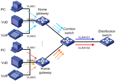
The application scenario of many-to-one VLAN mapping is the same as one-to-one VLAN mapping (as shown in Figure 1-1). Many-to-one VLAN mapping can map the uplink traffic streams from multiple VLANs of a user to the same VLAN, so that the upper-layer device can count the total traffic of a user by VLAN. After many-to-one VLAN mapping is configured, the network is as shown in Figure 1-3:
Figure 1-3 After many-to-one VLAN mapping
Configuring the DHCP Option 82 for Many-to-One VLAN Mapping
Option 82 is the relay agent option in the option field of the DHCP message. A DHCP snooping-enabled device that supports option 82 can insert the location information (including the port number and VLAN) of the DHCP client to the DHCP request. Upon receiving the DHCP request, the DHCP server can use the option to locate the DHCP client, thus securing and accounting the client.
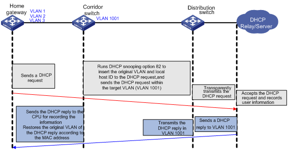
In a many-to-one VLAN mapping network, the DHCP server is usually deployed above the distribution layer. To record the client information correctly, the DHCP server must know the port through which a user is connected to the corridor switch and the original VLAN of the traffic. The port number locates the user, and the original VLAN identifies the device type of the client. For this purpose, you must enable DHCP snooping to support option 82 on the corridor switch, and configure option 82 to carry the original VLAN of traffic. After the configuration above is complete, the DHCP snooping option 82 works as shown in Figure 1-4:
Figure 1-4 How DHCP snooping option 82 works for many-to-one VLAN mapping
Configuring One-to-one VLAN Mapping
One-to-one VLAN Mapping Configuration Task List
Complete the following tasks to configure one-to-one VLAN mapping:
|
Task |
Remarks |
|
Use either approach |
|
![]()
l On a port, one-to-one VLAN mapping is mutually exclusive with VLAN VPN.
l One-to-one VLAN mapping is mutually exclusive with protocol-based VLAN.
l One-to-one VLAN mapping is mutually exclusive with many-to-one VLAN mapping. With many-to-one VLAN mapping enabled on a port, you cannot enable one-to-one VLAN mapping on any other port.
l One-to-one VLAN mapping is mutually exclusive with VLAN ID marking.
l One-to-one VLAN mapping is mutually exclusive with IP filtering. For more information about IP filtering, see DHCP Configuration.
Configuring a Global One-to-One VLAN Mapping Rule
Follow these steps to configure a global one-to-one VLAN mapping rule:
|
To do… |
Use the command… |
Remarks |
|
Enter system view |
system-view |
— |
|
Configure a global one-to-one VLAN mapping rule |
vlan-mapping vlan old-vlan-id remark new-vlan-id |
Required No global one-to-one VLAN mapping rule is configured by default |
|
Enter Ethernet port view |
interface interface-type interface-number |
— |
|
Enable one-to-one VLAN mapping on the port |
vlan-mapping enable |
Required Disabled by default |
![]()
l You cannot enable one-to-one VLAN mapping on a link aggregation group member port.
l When you configure a global one-to-one VLAN mapping rule and then enable one-to-one VLAN mapping on a port, selective QinQ is automatically enabled on the port.
Configuring a Port-Level One-to-One VLAN Mapping Rule
Follow these steps to configure a port-level one-to-one VLAN mapping rule:
|
To do… |
Use the command… |
Remarks |
|
Enter system view |
system-view |
— |
|
Enter Ethernet port view |
interface interface-type interface-number |
— |
|
Configure a port-level one-to-one VLAN mapping rule and enable one-to-one VLAN mapping on the port |
vlan-mapping vlan old-vlan-id remark new-vlan-id |
Required By default, no port-level one-to-one VLAN mapping rule is configured, and one-to-one VLAN mapping is disabled on all ports. |
![]()
l In a one-to-one VLAN mapping rule, one original VLAN can be mapped to only one target VLAN, and vice versa.
l To modify a one-to-one VLAN mapping rule, delete the rule and then define a new one.
l A global one-to-one VLAN mapping rule is mutually exclusive with a port-level one-to-one VLAN mapping rule.
l To use one-to-one VLAN mapping together with ARP detection properly, enable ARP detection in both the original VLAN and target VLAN. For more information about ARP detection, see ARP Configuration.
Configuring Many-to-One VLAN Mapping
Configuring a Many-to-One VLAN Mapping Rule
Follow these steps to configure a global many-to-one VLAN mapping rule
|
To do… |
Use the command… |
Remarks |
|
Enter system view |
system-view |
— |
|
Enter Ethernet port view of the downlink port |
interface interface-type interface-number |
— |
|
Configure a many-to-one VLAN mapping rule and enable many-to-one VLAN mapping on the port |
vlan-mapping n-to-1 vlan old-vlan-id remark new-vlan-id |
Required Repeat this step to map multiple original VLANs to the target VLAN |
![]()
l One-to-one VLAN mapping is mutually exclusive with many-to-one VLAN mapping. With many-to-one VLAN mapping enabled on a port, you cannot enable one-to-one VLAN mapping on any other port.
l You must assign the downlink port to not only the original VLANs, but also the target VLAN.
Configuring DHCP Snooping Option 82 to Carry the Original VLAN Information
Follow these steps to configure DHCP snooping option 82 to carry the original VLAN information:
|
To do… |
Use the command… |
Remarks |
|
Enter system view |
system-view |
— |
|
Globally configure DHCP snooping option 82 to carry the original VLAN information |
dhcp-snooping information ignore-vlanmapping |
Required By default, this function is disabled, and option 82 carries the target VLAN information. |
|
Enter Ethernet port view of the downlink port |
interface interface-type interface-number |
— |
|
Configure DHCP snooping option 82 to carry the original VLAN information on the port |
dhcp-snooping information ignore-vlanmapping |
Required By default, this function is disabled, and option 82 carries the target VLAN information. |
![]()
Globally configuring DHCP snooping option 82 to carry the original VLAN information takes effect on all ports.
One-to-One VLAN Mapping Configuration Example
Network Requirements
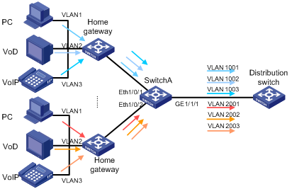
The network of a community is as shown in Figure 1-5. Each user has three applications: PC, VoD, and VoIP, which are assigned to VLAN 1, VLAN 2, and VLAN 3 on the home gateway.
Configure one-to-one VLAN mapping on the corridor switch to differentiate the uplink traffic streams of different users, so that the distribution switch can identify the user of a traffic stream by VLAN.
Figure 1-5 Network diagram for one-to-one VLAN mapping configuration
Configuration Procedure
# Create VLAN 1 (which exists by default), VLAN 2, and VLAN 3 on Switch A, and the target VLANs (VLANs 1001 through 1003 and VLANs 2001 through 2003).
<SwitchA> system-view
[SwitchA] vlan 2 to 3
[SwitchA] vlan 1001 to 1003
[SwitchA] vlan 2001 to 2003
# Because port Ethernet 1/0/1 of Switch A needs to receive the packets from original VLANs from a user and forward the traffic from the target VLANs from the distribution switch, Ethernet 1/0/1 should be a trunk or hybrid port. Configure Ethernet 1/0/1 as a hybrid port for example, assign Ethernet 1/0/1 to VLANs 1 through 3 and VLANs 1001 through 1003, and configure Ethernet 1/0/1 to send packets of these VLANs with tags kept.
[SwitchA] interface Ethernet 1/0/1
[SwitchA-Ethernet1/0/1] port link-type hybrid
[SwitchA-Ethernet1/0/1] port hybrid vlan 1 to 3 tagged
[SwitchA-Ethernet1/0/1] port hybrid vlan 1001 to 1003 tagged
[SwitchA-Ethernet1/0/1] quit
# Configure port Ethernet 1/0/2 in the same way.
[SwitchA] interface Ethernet 1/0/2
[SwitchA-Ethernet1/0/2] port link-type hybrid
[SwitchA-Ethernet1/0/2] port hybrid vlan 1 to 3 tagged
[SwitchA-Ethernet1/0/2] port hybrid vlan 1001 to 1003 tagged
[SwitchA-Ethernet1/0/2] quit
![]()
l If you configure Ethernet 1/0/1 and Ethernet 1/0/2 as trunk ports, you also need to assign them to the corresponding original VLANs and target VLANs.
l In the configuration above, the default VLAN of each port is VLAN 1. If you have changed the default VLAN of a port, you must assign the port to the default VLAN.
# Configure GigabitEthernet 1/1/1 of Switch A as a trunk port, and assign it to all target VLANs, including VLANs 1001 through 1003 and VLANs 2001 through 2003.
[SwitchA] interface GigabitEthernet 1/1/1
[SwitchA-GigabitEthernet1/1/1] port link-type trunk
[SwitchA-GigabitEthernet1/1/1] port trunk permit vlan 1001 to 1003
[SwitchA-GigabitEthernet1/1/1] port trunk permit vlan 2001 to 2003
[SwitchA-GigabitEthernet1/1/1] quit
# Define a one-to-one VLAN mapping rule on Ethernet 1/0/1 to map original VLAN 1 to target VLAN 1001.
[SwitchA] interface Ethernet 1/0/1
[SwitchA-Ethernet1/0/1] vlan-mapping vlan 1 remark 1001
# Map VLAN 2 to VLAN 1002, and VLAN 3 to VLAN 1003 in the same way.
[SwitchA-Ethernet1/0/1] vlan-mapping vlan 2 remark 1002
[SwitchA-Ethernet1/0/1] vlan-mapping vlan 3 remark 1003
[SwitchA-Ethernet1/0/1] quit
# Configure one-to-one VLAN mapping on port Ethernet 1/0/2 in the same way.
[SwitchA] interface Ethernet 1/0/12
[SwitchA-Ethernet1/0/12] vlan-mapping vlan 1 remark 2001
[SwitchA-Ethernet1/0/12] vlan-mapping vlan 2 remark 2002
[SwitchA-Ethernet1/0/12] vlan-mapping vlan 3 remark 2003
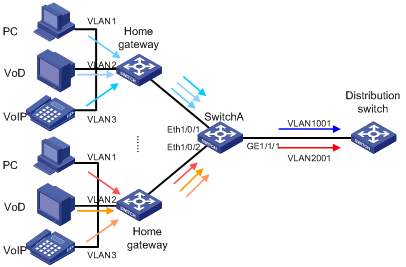
Many-to-One VLAN Mapping Configuration Example
Network Requirements
The network of a community is as shown in Figure 1-6. Each user has three applications: PC, VoD, and VoIP, which are assigned to VLAN 1, VLAN 2, and VLAN 3 on the home gateway.
The distribution switch collects per-user traffic statistics, without differentiating the traffic types. Therefore, configure many-to-one VLAN mapping on the corridor switch to map traffic streams from different users to different VLANs, so that the distribution switch can collect per-user traffic statistics by VLAN.
This example describes how to configure many-to-one VLAN mapping for two users: map all traffic streams from user A to VLAN 1001, and all traffic streams from user B to VLAN 2001.
At the same time, all terminals obtain IP addresses automatically through DHCP. To record the user information exactly, configure DHCP snooping option 82 to carry the original VLAN information on the corridor switch.
Figure 1-6 Network diagram for many-to-one VLAN mapping configuration
Configuration Procedure
Configuring Many-to-One VLAN Mapping
# Create VLAN 1 (which exits by default), VLAN 2, and VLAN 3, and the target VLANs (VLAN 1001 and VLAN 2001) on Switch A.
<SwitchA> system-view
[SwitchA] vlan 2 to 3
[SwitchA] vlan 1001 to 1003
[SwitchA] vlan 2001 to 2003
# Configure Ethernet 1/0/1 as a trunk port, and assign it to VLANs 1 through 3.
[SwitchA] interface Ethernet 1/0/1
[SwitchA-Ethernet1/0/1] port link-type trunk
[SwitchA-Ethernet1/0/1] port trunk permit vlan 1 to 3
# Assign Ethernet 1/0/1 to VLAN 1001, the target VLAN.
[Sysname-Ethernet1/0/1] port trunk permit vlan 1001
# Define a many-to-one VLAN mapping rule on Ethernet 1/0/1 to map original VLANs 1 through 3 to target VLAN 1001.
[Sysname-Ethernet1/0/1] vlan-mapping n-to-1 vlan 1 remark 1001
[Sysname-Ethernet1/0/1] vlan-mapping n-to-1 vlan 2 remark 1001
[Sysname-Ethernet1/0/1] vlan-mapping n-to-1 vlan 3 remark 1001
[Sysname-Ethernet1/0/1] quit
# Configure many-to-one VLAN mapping on port Ethernet 1/0/2 in the same way.
[SwitchA] interface Ethernet 1/0/2
[SwitchA-Ethernet1/0/2] port link-type trunk
[SwitchA-Ethernet1/0/2] port trunk permit vlan 1 to 3
[SwitchA-Ethernet1/0/2] port trunk permit vlan 2001
[Sysname-Ethernet1/0/2] vlan-mapping n-to-1 vlan 1 remark 2001
[Sysname-Ethernet1/0/2] vlan-mapping n-to-1 vlan 2 remark 2001
[Sysname-Ethernet1/0/2] vlan-mapping n-to-1 vlan 3 remark 2001
[Sysname-Ethernet1/0/2] quit
# Configure GigabitEthernet 1/1/1 as a trunk port, and assign it to VLANs 1001 and 2001.
[SwitchA] interface GigabitEthernet 1/1/1
[SwitchA-GigabitEthernet1/1/1] port link-type trunk
[SwitchA-GigabitEthernet1/1/1] port trunk permit vlan 1001 2001
Configuring DHCP Option 82
# Enable DHCP snooping on Switch A, and configure GigabitEthernet 1/1/1 as a trusted port.
[Sysname] dhcp-snooping
[Sysname] interface GigabitEthernet 1/1/1
[Sysname-GigabitEthernet1/1/1] dhcp-snooping trust
[Sysname-GigabitEthernet1/1/1] quit
# Configure DHCP snooping to support option 82 on Switch A.
[Sysname] dhcp-snooping information enable
![]()
You can configure option 82 in other ways. For more information, see DHCP Configuration.
# Configure Switch A to add Option 82 carrying the original VLAN information to the DHCP requests.
[Sysname] dhcp-snooping information ignore-vlanmapping