| Title | Size | Downloads |
|---|---|---|
| 01-Text.pdf | 1.47 MB |
- Table of Contents
- Related Documents
-
| Title | Size | Download |
|---|---|---|
| 01-Text | 1.47 MB |
Table of Contents
Examining the Installation Site
Temperature and Humidity Requirements
Grounding and Lightning Protection
Determining the Installation Position
Installing the Wall-Mounting Bracket on a Wall
Installing the AP on the Wall-Mounting Bracket
Locking the AP onto the Wall-Mounting Bracket (Optional)
The models listed in this manual are not applicable to all regions. Please consult the local agents for the models applicable to your region.
Introduction
The H3C WA2200 series WLAN access points (hereinafter referred to as the WA2200 series) are developed by Hangzhou H3C Technologies Co., Ltd. (hereinafter referred to as H3C). The WA2200 series consist of four models of access points (APs), which fall into two types according to the application environment: indoor and outdoor. The WA2200 series can serve as fit APs to cooperate with wireless switches or controllers or serve as fat APs to provide wireless access for WLAN users.
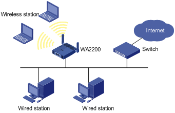
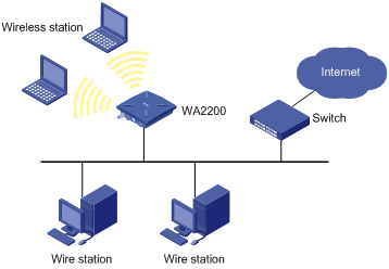
Figure 1-1 shows the typical deployment of the WA2200 series on hotspots.
Figure 1-1 Deployment of the WA2200 series on hotspots (Fat AP mode)
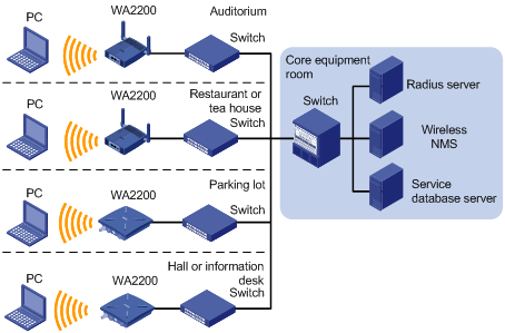
Figure 1-2 shows the appearance of the WA2200 series.
Figure 1-2 Appearance of the WA2200 series
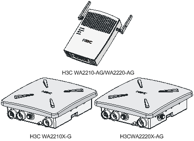
Table 1-1 Physical dimensions of the WA2200 series
|
Model |
Physical dimensions (H×W×D) |
Weight |
|
WA2210-AG/WA2220-AG, (indoor) |
40×166×118 mm (1.57×6.54×4.65 in.) |
0.5 kg (1.10 lb) |
|
WA2210X-G/WA2220X-AG, (outdoor) |
76×245×245 mm (2.99×9.65×9.65 in.) |
2 kg (4.41 lb) |
Hardware Configuration
The four models of the WA2200 series have different radio frequencies (RFs) and structures. Table 1-2 lists the protocols that each model supports as well as the chassis materials.
Table 1-2 Protocols that each model supports and the chassis material
|
Type |
Model |
Protocols and chassis material |
Power consumption |
802.3af PoE support |
|
Indoor |
WA2210-AG |
IEEE802.11a or IEEE802.11b/g, plastic |
8 W |
Yes |
|
WA2220-AG |
IEEE802.11a + IEEE802.11b/g, plastic |
10 W |
Yes |
|
|
Outdoor |
WA2210X-G |
IEEE802.11b/g, waterproof cast aluminum + plastic |
8 W |
Yes |
|
WA2220X-AG |
IEEE802.11a + IEEE802.11b/g, waterproof cast aluminum + plastic |
10 W |
No |
![]()
An outdoor AP will start the internal over-cold protection function in case of a temperature lower than –15°C, and the power consumption will increase 3 W to 5 W. In this case, you need to use an external PoE module to supply power to the AP.
The WA2200 series have extraordinary radio frequency (RF) performance and provide consummate service functions. With IP66 degree of protection, the outdoor models can be directly deployed outdoors to simplify the installation. The models of the WA2200 series are designed for application in various environments.
This section describes the hardware configurations and functions of the WA2200 series in detail.
LEDs
The positions and identifications of LEDs on the panel vary with the models. For details about these LEDs, see Table 1-3 and Table 1-4.
WA2210-AG/WA2220-AG
Figure 1-3 LEDs on the WA2210-AG/WA2220-AG
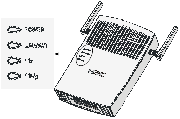
Table 1-3 Description of LEDs on the WA2210-AG/WA2220-AG
|
LED |
Color |
QTY |
Meaning |
|
POWER |
Green |
1 |
Displays the power supply status: l On: The power supply is normal. l Off/flashing: The power supply is not connected or well connected, or works abnormally. |
|
LINK/ACT |
Green |
1 |
Displays the link status of the Ethernet interface: l On: The link on the Ethernet interface is up. l Off: The link on the Ethernet interface is down. l Flashing: Data is being transmitted or received. |
|
11a |
Green |
1 |
Displays the wireless link status: l Off: The wireless link is not initialized or the link is faulty. l Flashing slowly: The wireless link is normal. l Flashing quickly: Data is being transmitted or received. |
|
11b/g |
Green |
1 |
Displays the wireless link status: l Off: The wireless link is not initialized or the link is faulty. l Flashing slowly: The wireless link is normal. l Flashing quickly: Data is being transmitted or received. |
![]()
The WA2210-AG is a single-RF device. The 11a and 11b/g LEDs cannot be on or flash at the same time.
WA2210X-G/WA2220X-AG
Figure 1-4 LEDs on the WA2210X-G
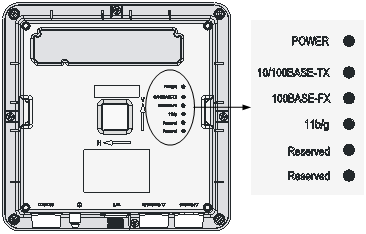
Figure 1-5 LEDs on the WA2220X-AG
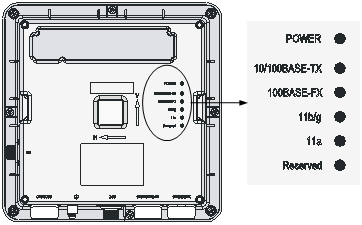
Table 1-4 Description of LEDs on the WA2210X-G/WA2220X-AG
|
LED |
Color |
QTY |
Meaning |
|
POWER |
Green |
1 |
Displays the power supply status: l On: The power supply is normal.. l Off/flashing: The power supply is not connected or well connected or the device works abnormally. |
|
10/100BASE-TX |
Green |
1 |
Displays the status of the Ethernet interface: l On: The link on the Ethernet interface is up. l Off: The link on the Ethernet interface is down. l Flashing: Data is being transmitted or received. |
|
100BASE-FX |
Yellow |
1 |
Displays the status of the optical interface: l On: The link on the optical interface is up. l Off: The link on the optical interface is down. l Flashing: Data is being transmitted or received. |
|
11a |
Green |
1 |
Displays the wireless link status: l Off: The wireless link is not initialized or the link is faulty. l Flashing slowly: The wireless link is normal. l Flashing quickly: Data is being transmitted or received. |
|
11b/g |
Green |
1 |
Displays the wireless link status: l Off: The wireless link is not initialized or the link is faulty. l Flashing slowly: The wireless link is normal. l Flashing quickly: Data is being transmitted or received. |
![]()
l The WA2210X-G is a single-RF device and has no 11a LED.
l The word “reserved” means the LED is reserved for future use.
Interfaces
The interfaces provided by the WA2200 series include:
l 2.4 GHz or/and 5 GHz antenna interface(s)
l Console interface
l Ethernet interface (optical and electrical)
l Power interface for indoor models
![]()
In addition, a reset button (indoor and enhanced models), a security slot (indoor and enhanced models), and a grounding screw (outdoor models) are provided.
Table 1-5 describes the interfaces provided by each model.
Table 1-5 Descriptions of interfaces on WA2200 series WLAN access points
|
Model |
Interface |
Standards and protocols |
Description |
|
WA2210-AG/WA2220-AG |
Antenna interface 1 |
IEEE802.11b/g |
WA2210-AG: Main antenna interface, 2.4/5-GHz WA2220-AG: 2.4-GHz antenna interface |
|
Console interface |
RS/EIA-232 |
The console interface is used for device configuration and management. |
|
|
Ethernet interface |
IEEE802.3 IEEE802.3u IEEE802.3af |
The Ethernet interface can serve as an uplink interface of the device to access the Internet or a MAN, and can simultaneously serve as a PoE interface. |
|
|
Power interface |
N/A |
The power interface is used for +48 VDC power supply to the device. |
|
|
Antenna interface 2 |
IEEE802.11a |
WA2210-AG: Auxiliary antenna interface, 2.4/5-GHz WA2220-AG: 5-GHz antenna interface |
|
|
WA2210X-G/WA2220X-AG |
Ethernet optical interface |
IEEE802.3 SFP MSA SFF-8472 |
The Ethernet optical interface can serve as an uplink interface to access the Internet or a MAN. The Ethernet optical interface is used to connect an SFP module. In practice, either the Ethernet electrical interface or the Ethernet optical interface is used. |
|
Ethernet electrical interface |
IEEE802.3 IEEE802.3u IEEE802.3af |
The Ethernet electrical interface can serve as an uplink interface of the device to access the Internet or a MAN, and can simultaneously serve as a PoE interface. |
|
|
Antenna interface 1 |
IEEE802.11b/g |
This antenna interface is used to connect a 2.4-GHz antenna or a feeder. |
|
|
Console interface |
RS/EIA-232 |
The console interface is used for device configuration and management. |
|
|
Antenna interface 2 |
IEEE802.11a |
This antenna interface is used to connect a 5-GHz antenna or a feeder. |
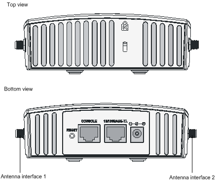
Interfaces provided by WA2210-AG/WA2220-AG
Figure 1-6 Interfaces on WA2210-AG/WA2220-AG
![]()
l WA2210-AG is a single-RF device. Viewed from the front, the antenna interface on the left (antenna interface 1 in Figure 1-6) is the main antenna interface, while the one on the right (antenna interface 2 in Figure 1-6) is the auxiliary antenna interface. When there is only one antenna, the antenna must be installed on the main antenna interface.
l WA2220-AG is a dual-RF device. Viewed from the front, the antenna interface on the left (antenna interface 1 in Figure 1-6) is the 2.4-GHz antenna interface, while the one on the right (antenna interface 2 in Figure 1-6) is the 5-GHz antenna interface.
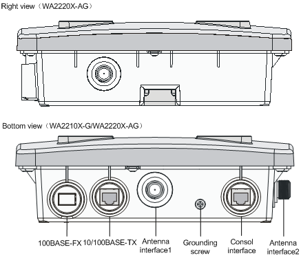
Interfaces provided by WA2210X-G/WA2220X-AG
Figure 1-7 Interfaces on WA2210X-G/WA2220X-AG
![]()
WA2210X-G is a single-RF device and provides no 5-GHz antenna interface.
This chapter describes the preparations for WA2200 installation, including preparation of installation tools, environment examination, and unpacking & inspection.
Safety Precautions
![]()
Installation and removal of the unit and its accessories must be carried out by qualified personnel. You must read all of the Safety Instructions supplied with your device before installation and operation.
![]()
Installation und Ausbau der Anlage und ihrer Zubehörteile müssen von qualifiziertem Personal realisiert werden. Sie müssen vor der Installation oder Bedienung allen beiliegenden Sicherheitshinweise lesen.
![]()
负责安装和日常维护本设备的人员必须具备安全操作基本技能。在操作本设备前,请务必认真阅读和执行产品手册规定的安全规范。
Preparing Installation Tools
When installing the AP, you may need the tools listed in Table 2-1. You should select the appropriate tools according to the installation environment.
Table 2-1 List of installation tools
|
Type of tool |
Indoor installation |
Outdoor installation |
|
General tools |
1-meter-long ruler, marking pen, knife, and percussion drill with matching drills |
Digging tool, adjustable spanner, and vices |
|
Special tools |
Cable stripper, crimping pliers, and RJ-45 crimping pliers |
Cable stripper, crimping pliers, RJ-45 crimping pliers, waterproof tape, and fiber fusion splicer |
|
Auxiliary tools |
Ladder and rubber hammer |
Ladder |
![]()
Table 2-1 is only for reference. If you install the AP on a desk, none of the above tools is required; if you install the AP on top of or under eave of a building, no digging tool is required.
Examining the Installation Site
Before installation, you should examine the installation site to keep the AP under a good operational environment. You can examine the installation site from the following two aspects:
Installation Site Selection
Keep the AP away from places that are susceptible to high temperature, dust, inflammable, explosive, electromagnetic interference (high power radar, radio station, and transformer), unstable voltage, heavy vibration, or loud noise. The installation site should be dry, without any leakage, dripping, or dew .The AP should be at least 500 m (0.31 mi) away from the seaside and should not face the direction of sea wind.
In engineering design, the site should be selected according to the network planning and technical requirements of communications equipment, as well as the considerations such as climate, hydrology, geology, earthquake, electric power, and transportation.
Temperature and Humidity Requirements
Table 2-2 lists the operating temperature and humidity requirements.
Table 2-2 Environment specifications
|
Specification |
Range |
|
Operating temperature (indoor) |
-10°C to 55°C (14°F to 131°F) |
|
Operating temperature (outdoor) |
–40°C to +65°C (–40°F to +149°F) |
|
Storage temperature (indoor) |
–40°C to +70°C (–40°F to +158°F) |
|
Storage temperature (outdoor) |
–40°C to +85°C (–40°F to +185°F) |
|
Operating humidity (noncondensing) |
5% to 95% |
Power Supply
The WA2200 series can be powered through 802.3af-compliant power over Ethernet (PoE) (except WA2220X-AG) or an external power adaptor. For details see the Table 2-3.
Outside China it is recommended that this unit be PoE powered. Please see the H3C/3Com product catalogues for a range of 802.3af compatible power sources.
|
Power Source |
Connection Details |
Ordering information |
|
AC/DC Power Adapter |
H3C WA2200 series access points can accept power from an AC/DC power adapter. Input specification is as follows:
+48V Connect the adapter’s power jack to the AP power interface. |
If you need an AC/DC power adapter for your H3C WA2200 series access point, you must use the FSP025-1AD207A adapter(part number 0231A0EQ) which is available from H3C/3Com. |
|
Power over Ethernet (PoE, IEEE 802.3af standard) power source |
H3C WA2200 series access points (except WA2220X-AG) can accept power from a PoE power source. No DC power adapter is required. Connect the PoE cable directly to the 10/100 Base-TX Ethernet connector. |
Please see the H3C/3Com product catalogues for a range of 802.3af compatible power sources. |
Grounding and Lightning Protection
Table 2-4 Grounding and lightning protection requirements
|
SN |
Item |
Requirements |
|
1 |
Grounding resistance |
l The earth resistance is usually required to be less than 5 ohms, and less than 10 ohms in an area with less than 20 thunderstorm days a year. If a piece of angle steel is buried as the earthing conductor, the earth resistance is required to be less than 10 ohms. In an area with a higher earth resistance, reduce the earth resistance by using brine or resistance reducing agent around the earthing conductor. l The top of the earthing conductor should be at least 0.7 m (2.30 ft) away from the ground surface. In cold areas, the earthing conductor should be buried below the frozen soil layer. |
|
2 |
Device protection ground (PGND) |
l If a grounding strip is available, connect the yellow and green ground cable of the AP to the grounding strip. If you need to make a grounding cable, the cable should be with a cross-section area of at least 6 mm2 (0.24 in2) and a length of no longer than 3 m (9.84 ft). l If no grounding strip is available, bury a piece of angle steel/steel tube at least 0.5 m (1.64 ft) long in the earth to serve as the earthing conductor. In the case of a piece of angle steel, the size should be at least 50 mm × 50 mm × 5 mm (1.97 in. × 1.97 in. × 0.20 in.); in the case of a piece of steel tube, it must be zinc-plated and have a wall thickness of at least 3.5 mm (0.14 in.). Weld the yellow and green ground cable of the AP onto the earthing conductor and use anti-erosion treatment on the welding joint. The grounding cable should be as short as possible and must not be coiled. l Ensure that the grounding points of all the lightning arresters of the AP and the peer device of the AP are well grounded. |
|
3 |
Grounding lead-in |
A grounding lead-in is a metal conductor connecting a grounding net and a grounding strip. The grounding cable of the AP should be connected to the grounding strip. The grounding lead-in must be 30 m (98.43 ft) or shorter. A piece of zinc-coated flat steel with a cross-section area of 40 × 4 mm (1.57 × 0.16 in) or 50 × 5 mm (1.97 × 0.20 in) is recommended. Connect the grounding strip and the grounding lead-in of the AP through the yellow and green ground cable with an area of 35 mm2 (1.38 in.), or weld them directly. Use anti-erosion treatment on the welding joint. |
|
4 |
Power grounding (AC) |
l Use a power cord with a protective earth (PE). Do not use a power cord with only an L line and an N line. l The neutral line of the power cord should not be connected with the PGND of other communications equipment. The L and N lines cannot be connected |
|
5 |
Lightning arrester |
In plain areas, the protection angle of the lightning rod should be less than 45 degrees. In mountainous areas or lightning areas, the protection angle should be less than 30 degrees. The lightning protection grounding (for example, the grounding of the lightning rod) should be connected to the earthing conductor of the equipment room. |
|
6 |
Feeder |
l The antenna support is already prepared according to the design requirements. l A feeder lightning rod is already installed and grounded according to the design requirements. |
|
7 |
Outdoor lightning arrester |
Power lightning arrester, port lightning protector, and feeder lightning arrester are recommended for outdoor installations. The power lightning arrester and the feeder lightning arrester should be near the AP, and the network interface lightning arrester should be near the peer device of the AP. The network interface lightning arrester should be installed where the network cable is just led out of the room. |
|
8 |
Network cable |
Use a shielded twisted pair cables for an AP used outdoors. Ensure that the devices at the two ends of the cable are well grounded. |
After you have completed the preparations, you can start installing the AP. The installation of indoor models is different from that of the outdoor models. For details, refer to 3 “Installation of Indoor APs” on page 3-1 and 4 “Installation of Outdoor APs” on page 4-1.
You can directly place an indoor model (including the enhanced model) on a desk. The rubber feet on the bottom of the AP help you to place it horizontally. Or you can fix it onto a wall by using the wall-mounting bracket. The following introduces the wall-mounting procedure of the indoor models and enhanced model in detail.
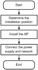
Installation Flowchart
Figure 3-1 shows the installation flowchart of the indoor models and enhanced model.
Figure 3-1 Installation flowchart of an indoor AP
Determining the Installation Position
Determine the installation position by observing the following principles:
l Leave as few obstacles (such as wall and ceiling) as possible between the AP and stations.
l Keep the AP far away from electronic devices (such as microwave oven) that may generate RF noise.
l Install the AP in a place where it will not hinder people’s daily work and life.
l Do not install the AP in a place where water seeping, water soaking, and condensing occur. Prevent water or moisture from entering the AP.
![]()
Ensure the intensity and structure of the ceiling meet the requirements for ceiling mounting of the AP. You are recommended to reinforce the ceiling using boards if it is not strong enough. A padlock is required to prevent any falloff in case of shocks.
Installing the AP
The following describes how to install the AP on a wall.
l Installing the Wall-Mounting Bracket on a Wall
l Installing the AP on the Wall-Mounting Bracket
l Locking the AP onto the Wall-Mounting Bracket (Optional)
Installing the Wall-Mounting Bracket on a Wall
Follow these steps to install the wall-mounting bracket on a wall:
Step1 Drill holes 6 mm (0.24 in) in diameter on the wall where the AP should be mounted. The drilled holes should correspond to those in the wall-mounting bracket. There are eight installation holes in total in the wall-mounting bracket. You should select at least four holes for installation.
Figure 3-2 Screw hole locations and screw hole size (in mm)

Step2 Insert the pointed end of anchors into the drilled holes and tap the flat end of anchors with a rubber hammer until they are all flush with the wall surface.
Step3 Align the holes in the wall-mounting bracket with the anchors and insert screws through the installation holes into the anchors, as shown in Figure 3-3.
Step4 Adjust the position of the wall-mounting bracket and tighten the screws.
Figure 3-3 Install the wall-mounting bracket
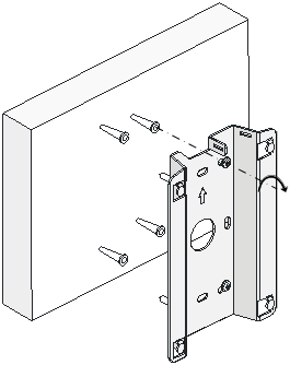
![]()
When installing the wall-mounting bracket, position it so that the arrowhead points upward.
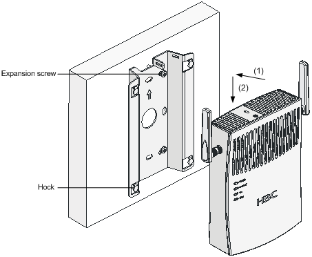
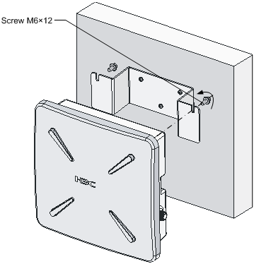
Installing the AP on the Wall-Mounting Bracket
Follow these steps to install the AP on the wall-mounting bracket:
Step1 Align the AP with the hooks on the wall-mounting bracket and hang the AP on the bracket (see (1) in Figure 3-4).
Step2 Then press the AP downward to fix it (see (2) in Figure 3-4).
Figure 3-4 Fix the indoor AP onto the wall-mounting bracket
Locking the AP onto the Wall-Mounting Bracket (Optional)
The indoor APs have a security slot on the top, which can be used to lock the AP onto the wall-mounting bracket to prevent theft.
Follow these steps to lock the AP onto the wall-mounting bracket:
Step1 Insert the locking plate into the security slot on the top of the AP (see (1) in Figure 3-5).
Step2 Turn the locking plate counterclockwise until the hole on the locking plate is aligned with the hole in the wall-mounting bracket (see (2) in Figure 3-5).
Step3 Put the latch through the two holes that are aligned in step 2 (see (3) in Figure 3-5).
Step4 Lock the latch with a lock.
Figure 3-5 Lock the indoor AP onto the wall-mounting bracket
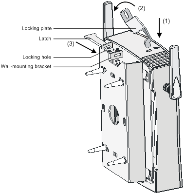
![]()
The lock is user supplied.
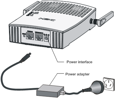
Connecting the Power Supply
Local Power Supply
Connect the AP to the power adapter and then to the power source, as shown in Figure 3-6.
Figure 3-6 Local power supply connection
Power over Ethernet
If the uplink device of the AP is a PoE switch or the like, use an Ethernet cable to directly connect the Ethernet interface of the AP to the PoE device.
![]()
l In the case of PoE, you do not need to connect the power interface to a power source. You only need to connect one end of an Ethernet cable to the Ethernet interface of the AP and the other end to an Ethernet interface of a PoE switch (for example, Ethernet switch).
l Identify the silkscreen on the device to avoid taking the console interface for the Ethernet interface and vice versa.
Connecting the Network
Connect the Ethernet interface of the AP to an Ethernet interface of the switch to implement Internet or MAN access, as shown in Figure 3-8.
Figure 3-8 Connect the AP to the network
The outdoor models of the WA2200 series are H3C WA2210X-G and H3C WA2220X-AG. You can select an appropriate model according to the actual requirement. The two outdoor models are waterproof, dustproof, and lightningproof.
Installation Flowchart
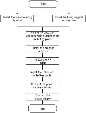
You can install your outdoor AP on a wall or a pole. As a wireless device, the installation location directly affects the coverage and performance of wireless signals. Therefore, it is recommended that the AP be installed by a professional. Figure 4-1 shows the installation flowchart of the outdoor models.
Figure 4-1 Installation flowchart of the outdoor models
Installing the AP
The following describes how to install the AP on a wall and a pole respectively.
Installing the AP on a wall
Figure 4-2 illustrates the installation flowchart of the AP on a wall.
Figure 4-2 Installation flowchart of the AP on a wall

1) Mark
|
Step |
Operation |
|
1 |
Put the wall-mounting bracket on the installation position against the wall. |
|
2 |
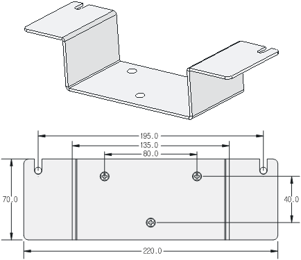
Mark three expansion screw holes on the wall. For the distance (in mm) between the expansion screw holes, see Figure 4-3. |
![]()
The wall-mounting bracket is not supplied unless ordered.
Figure 4-3 Wall-mounting bracket structure and positions of screw holes
2) Drill holes
|
Step |
Operation |
|
1 |
Use a percussion drill with a 6-mm (0.24-in) bit to drill holes on the three markings. |
Observe the following precautions when drilling:
l Hold the drill handle with both hands, with the bit perpendicular to the wall surface, and prevent wall damage or tilted holes.
l The hole depth should be the anchor length plus the bit length. Each hole should have the same depth. Remove the dust from the hole before measuring the hole depth. Use a vacuum cleaner to prevent dust from spreading around.
l If the wall surface is too solid and slippery to locate the bit, punch a notch first.
3) Install anchors
![]()
Before installation, remove dust inside and around all holes with a vacuum cleaner, and then measure the distances between holes. If there is a large error, mark and drill holes again.
|
Step |
Operation |
|
1 |
Put an anchor into each hole vertically. |
|
2 |
Tap the flat end of the anchor with a rubber hammer until the anchor is flush with the wall surface. |
4) Fix the wall-mounting bracket
|
Step |
Operation |
|
1 |
Align the three holes in the wall-mounting bracket with the anchors and insert three expansion screws through the installation holes into the anchors. |
|
2 |
Adjust the position of the wall-mounting bracket and tighten the expansion screws. |
5) Fix the AP
|
Step |
Operation |
|
1 |
Method 1: Align the two installation holes in the AP with the corresponding holes in the wall-mounting bracket and then use two screws to fix them. Method 2: Insert a screw into each installation hole in the AP, but do not tighten them. Then insert the screws into the corresponding holes in the wall-mounting bracket. |
|
2 |
Tighten the screws so that the AP touches against the wall-mounting bracket, as shown in Figure 4-4. |
Figure 4-4 Install the outdoor AP on a wall
Installing the AP on a pole
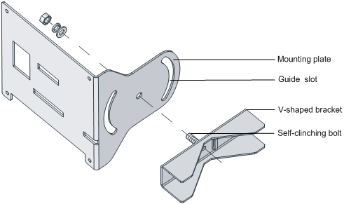
The fixing support for installing the outdoor AP on a pole consists of two major components: a pair of V-shaped brackets and a mounting plate. The outdoor AP can be fixed on a vertical or horizontal pole with an outer diameter of 60 to 110 mm (2.36 to 4.33 in) through the fixing support. The mounting plate and the V-shaped bracket are fixed through the self-clinching bolt and a nut, as shown in Figure 4-5.
Figure 4-5 Mounting plate and V-shaped bracket
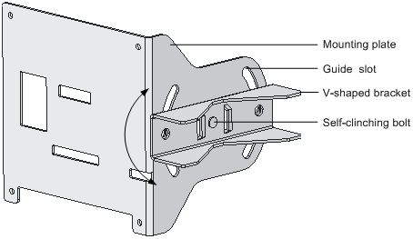
You can adjust the angle of the AP as needed. Follow these steps to adjust the angle of the AP:
Step1 Follow the arrowhead shown in Figure 4-6 to turn the V-shaped bracket with the self-clinching bolt as the pivot to adjust the angle of the mounting plate.
Step2 Use tie-bar bolts through the guide slots and nuts (see Figure 4-8) to fix the mounting plat and V-shape bracket.
Figure 4-6 Adjust the angle of the AP
On the top of a building, the outdoor AP is usually installed on a pole.
Follow these steps to install the outdoor AP on a pole:
Step3 As shown in Figure 4-7, fix the pole base onto the top surface of a building or onto a cement pier.
Step4 Fix the mounting plate onto one V-shaped fixing bracket with a self-clinching bolt.
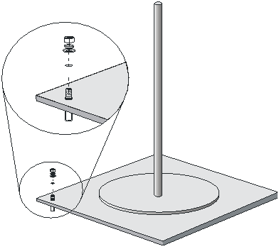
Step5 Fix the pair of V-shaped fixing brackets on a vertical or horizontal pole with tie-bar bolts, flat washers, spring washers, and nuts (see Figure 4-8 or Figure 4-9).
Figure 4-8 Install the outdoor AP on a vertical pole
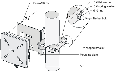
Figure 4-9 Install the outdoor AP on a horizontal pole
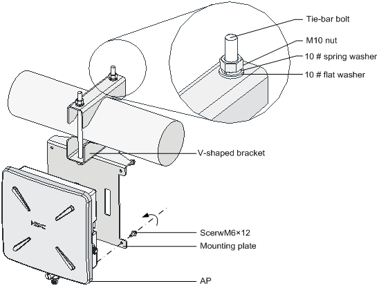
Step6 Fix the AP onto the mounting plate with screws (see the dashed line and arrow in Figure 4-8 or Figure 4-9).
![]()
You can first install the fixing support onto the pole and then the AP onto the mounting plate, or vice versa.
Installing an Outdoor Antenna
There are two types of outdoor antennas: directional antenna and omni antenna. An omni antenna can be directly installed on an outdoor AP.
Installing a directional outdoor antenna on a pole
![]()
You should select such an installation location for the pole that the antenna direction and tilt could be adjusted freely.
Follow these steps to install a pole on a parapet:
Step1 Weld the lightning rod onto the tip of the pole.
Step2 Install the pole on a parapet or cement pier.
Step3 Use a 40 × 4 mm (1.57 × 0.16 in) flat steel to connect the pole to the ground grid
Step4 Use pole-mounting brackets to install the directional outdoor antenna on the pole.
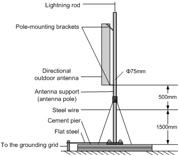
The pole should be vertical to the building top surface, as shown in Figure 4-10 and Figure 4-11.
Figure 4-10 Install a directional outdoor antenna on a parapet
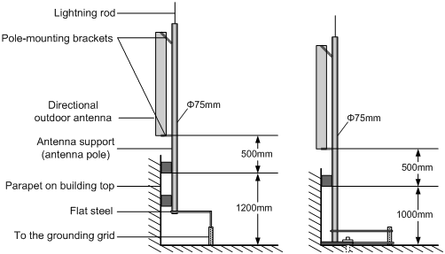
Figure 4-11 Install a directional outdoor antenna on a building top surface or cement pier
l If there are parapets around the building top and the parapets are 1200 mm (47.24 in) high or higher, install the antenna pole on a parapet with expansion bolts and fix the directional outdoor antenna onto the pole with pole-mounting brackets (see the left diagram in Figure 4-10).
l If there are parapets around the building top and the parapet height is less than 1200 mm (47.24 in), fix one point of the pole to the parapet with one expansion bolt and the other point to the building top surface with another expansion bolt, and fix the directional outdoor antenna onto the pole with pole-mounting brackets (see the right diagram in Figure 4-10).
l If there is no parapet around the building top, first use expansion bolts to secure the pole vertically on the building top surface or cement pier, and then use pole-mounting brackets to fix the directional outdoor antenna onto the pole, as shown in Figure 4-11.
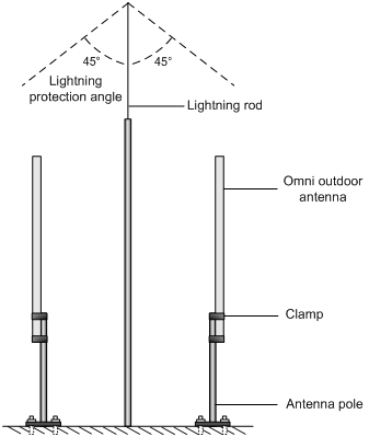
Installing an omni outdoor antenna on a pole
When installing an omni outdoor antenna on a pole, observe the following precautions:
l The pole should be 35 to 50 mm (1.38 to 1.97 in) in diameter. Usually, a round steel with a diameter of 50 mm (1.97 in) is adopted.
l The top of the pole should be flush with the upper clamp, as shown in Figure 4-12.
l The antenna height should meet the signal coverage requirement and the tip of the antenna should fall within the 45° protection angle of the lightning rod.
Usually, no lightning rod is directly soldered onto an omni antenna pole (no metal object is allowed within one meter in the horizontal direction of the omni antenna). Instead, a lightning rod is set on a separate pole between two omni antenna poles and the lightning rod is high enough to keep the tip of omni antennas within the protection angle.
Figure 4-12 Install omni antennas
If the lightning rod cannot be installed on a separate pole owing to the environment limitation, the installation method shown in Figure 4-13 can be adopted. In this case, the lightning rod pole should be at least one meter away from the omni antenna pole.
Figure 4-13 Install an omni antenna under a special environment
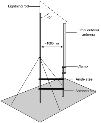
![]()
In Figure 4-13, the antenna pole is welded with two angle steels to the lightning rod pole, instead of a cement pier.
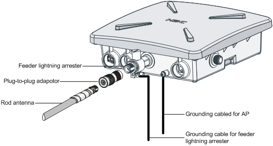
Installing an omni antenna on the AP directly
A low-gain omni rod antenna can be directly installed on the AP. The installation procedure is as follows:
Step1 Screw a feeder lightning arrester onto the downward 2.4-GHz antenna interface.
Step2 Screw one end the plug-to-plug adaptor onto the feeder lightning arrester.
Step3 Screw the omni rod antenna onto the other end of the plug-to-plug adaptor.
Step4 Ground the feeder lightning arrester with a grounding cable. (See Figure 4-14)
Step5 Ground the AP with a grounding cable.
Figure 4-14 Install an omni antenna on the AP directly
![]()
l After the omni antenna is installed on the AP, the antenna should be at least one meter away from the pole or other metal objects.
l The outdoor AP and the feeder lightning arrester are each equipped with a 3-meter-long grounding cable. If the length is not long enough, you need to supply longer grounding cables. For the grounding requirements, refer to section “Grounding and Lightning Protection” on page 2-3.
Connecting External Cables
![]()
l Before connecting external cables, check that all power lines are disconnected, and that there is no dangerous voltage on the neutral (N) line.
l Protect the AP and cables against water and avoid external cable damage.
External cables to be connected include an RF cable, Ethernet cable, fiber cable, grounding cable, and power cord.
Connecting the RF cable
The RF cable refers to the cable between the antenna interface and the antenna. Follow these steps to connect the RF cable:
Step1 Screw one end of the feeder lightning arrester onto the antenna interface.
Step2 Connect one end of the RF cable to the feeder lightning arrester and the other end to the outdoor antenna.
Step3 Wrap each joint with insulation tape first, and then with waterproof tape.
![]()
l It is recommended to install a feeder lightning arrester on each antenna interface and ground it well.
l A finished RF cable with a fixed length can be shipped with the AP if ordered. If such an RF cable is not long enough, you should provide a longer RF cable and an N-type RF connector and prepare the cable at the site.
l Distinguish the stickiness of the two sides of waterproof tape. Before wrapping a cable joint, stretch the waterproof tape so that the width is three quarters of the original one to ensure the tightness.
Connecting an Ethernet cable
![]()
Follow the steps below to connect an Ethernet cable. Otherwise, the AP may get damaged
Step1 As shown in Figure 4-15, Figure 4-16 and Figure 4-17, route the waterproof Ethernet cable from the equipment room to the AP installation location.
Figure 4-15 Connect the Ethernet electrical interface to the uplink device
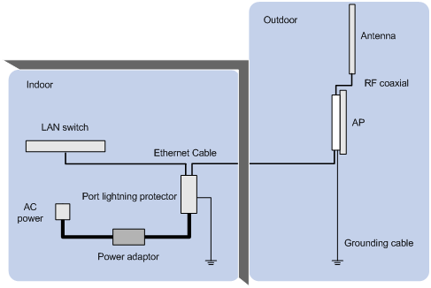
Figure 4-16 Connect the Ethernet optical interface to the uplink device
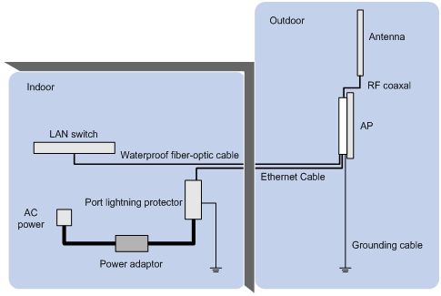
Figure 4-17 Exploded view of the port lightning protector (PoE)
![]()
l If the uplink device is a PoE switch, no port lightning protector or power adapter is required. It is not recommended to provide power to the AP using a PoE switch.
l If the Ethernet optical interface serves as an uplink data interface, the Ethernet electrical interface only serves as a PoE interface.
l There are two Ethernet interfaces on the power injector, as shown in Figure 4-17. Ensure that the Ethernet interface on the surge side is connected to the AP.
l Whether the AP is powered by a PoE switch or the power injector, ensure that the AP has been installed as required before power-on.
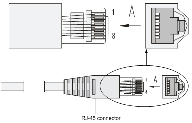
Step2 Prepare an Ethernet cable connector
Since an Ethernet cable needs to pass through a waterproof cover for waterproof purpose (an Ethernet cable with an RJ-45 connector is unable to pass through), you need to prepare an Ethernet cable connector on site. Usually a category-5 or enhanced category-5 twisted pair cable is adopted. Figure 4-18 shows an Ethernet cable connector.
Figure 4-18 Ethernet cable connector
Ethernet cables fall into straight-through Ethernet cables and crossover Ethernet cables.
l Straight-through Ethernet cable: The wires of a twisted pair cable are crimped in the same sequence in the RJ-45 connectors at both ends. A straight-through cable is used to connect a terminal device (such as PC or router) to a hub or LAN Switch.
l Crossover Ethernet cable: The wires of a twisted pair cable are crimped in different sequences in the RJ-45 connectors at both ends. A crossover Ethernet cable is used to connect a terminal device (such as PC or router) to another terminal device. You can make such a cable by yourself.
Table 4-1 RJ-45 straight-through Ethernet cable pinouts
|
Pin of RJ-45 connector |
Signal |
Category-5 twisted pair cable |
Signal direction |
Pin of RJ-45 connector |
|
1 |
Tx+ |
White (orange) |
à |
1 |
|
2 |
Tx- |
Orange |
à |
2 |
|
3 |
Rx+ |
White (green) |
ß |
3 |
|
4 |
— |
Blue |
— |
4 |
|
5 |
— |
White (blue) |
— |
5 |
|
6 |
Rx- |
Green |
ß |
6 |
|
7 |
— |
White (brown) |
— |
7 |
|
8 |
— |
Brown |
— |
8 |
Table 4-2 RJ-45 crossover Ethernet cable pinouts
|
Pin of RJ-45 connector |
Signal |
Category-5 twisted pair cable |
Signal direction |
Pin of RJ-45 connector |
|
1 |
Tx+ |
White (orange) |
à |
3 |
|
2 |
Tx- |
Orange |
à |
6 |
|
3 |
Rx+ |
White (green) |
ß |
1 |
|
4 |
— |
Blue |
— |
4 |
|
5 |
— |
White (blue) |
— |
5 |
|
6 |
Rx- |
Green |
ß |
2 |
|
7 |
— |
White (brown) |
— |
7 |
|
8 |
— |
Brown |
— |
8 |
![]()
l When distinguishing or preparing these two types of Ethernet cables, you can refer to the above tables. Since the Ethernet interface of the AP is auto-sensing, these two types of Ethernet cables can be used for the Ethernet interface.
l Refer to Table 4-1 and Table 4-2 to arrange the wire sequence when preparing an Ethernet cable. Otherwise, the communication quality will not be high, even if the devices at both ends can communicate.
l The Ethernet cable should be equipped with a waterproof sheath when routed outdoors. If possible, cable routing in waterproof tubes is recommended.
Step3 Insert the Ethernet cable connector into the Ethernet interface, as shown in Figure 4-19.
Figure 4-19 Insert the Ethernet cable connector into the Ethernet interface
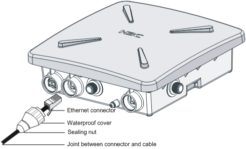
Step4 First tighten the waterproof cover and then the sealing nut.
Step5 Use waterproof tape to wrap the joint between the waterproof cover and the cable.
Connecting an optical fiber
![]()
Be sure to follow the instructions below when connecting a fiber cable. Otherwise, the AP may get damaged.
When connecting the AP to the remote device through a fiber cable, use an appropriate SFP module. The SFP modules provided by H3C can be used outdoor. These SFP modules use single-mode optic fibers and have a transmission distance of 15 km (9.32 miles).
You need to configure an SFP module and a waterproof cover when connecting the AP to an uplink device through a fiber cable, as shown in Figure 4-20.
Figure 4-20 Connect a fiber cable
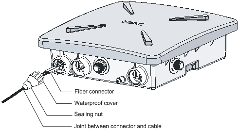
Follow these steps to connect a fiber cable:
Step1 Insert an SFP module into the Ethernet optical interface on the AP.
Step2 Insert the LC connectors with a waterproof cover into the two optical interfaces on the SFP module.
Step3 First tighten the waterproof cover and then the sealing nut.
Step4 Use waterproof tape to wrap the joint between the waterproof cover and the fiber cable.
![]()
The fiber cable is a 10-meter tail fiber with a waterproof cover. One end of the fiber is an LC connector with a waterproof joint, and the other end is an SC connector, which can be connected to a fiber or device. For users using an optical cable terminal box, you can insert the SC connector of the tail fiber to the SC socket on the optical cable terminal box. The mark A on the SC socket is the RX end of the AP, which should be connected to the TX end of the peer device, and the mark B is the TX end of the AP, which should be connected to the RX end of the peer device. Optical cable terminal boxes are not waterproof, and therefore should be installed indoors or in a waterproof chassis. For users using an optical cable splice closure, you need to cut off the SC connector, and then wrap the fiber. Note that the A and B marks correspond to the RX and TX ends of the AP respectively and should be connected to the TX and RX ends of the peer device respectively when you wrap the fiber. Optical cable splice closures are waterproof and can be buried or installed overhead.
Connecting the power cable
The WA2210X-G and WA2220X-AG AP support external PoE power supply.
l To use a PoE switch to supply power to the AP, connect the port of the switch to the 10/100BASE-TX port of the AP through an Ethernet cable.
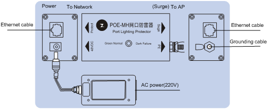
l To supply power through a port lightning protector, connect the devices as shown in Figure 4-21.
Figure 4-21 Exploded view of the port lightning protector (PoE)
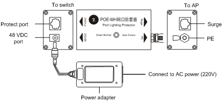
Step1 Insert the plug of the power adapter into the 48 VDC port of the POE-MH port lightning protector.
Step2 Connect the port of the switch to the protect port of the POE-MH port lightning protector using an Ethernet cable.
Step3 Connect the grounding cable to the PE port of the POE-MH port lightning protector, tighten it, and make sure that the grounding cable is well grounded.
Step4 Connect the surge port of the POE-MH port lightning protector to the 10/100BASE-TX port of the AP using an Ethernet cable.
![]()
l If a PoE switch is used to supply power, no port lightning protector or power adapter is required. It is not recommended to provide power to the AP using a PoE switch over a long distance.
l To supply power to the AP through a port lightning protector, you need to connect the port lightning protector to the switch. The switch does not need to be a PoE switch and you need to use a power adapter to provide power to the remote AP.
l No matter whether the AP is powered by a PoE switch or by a power adapter through a port lightning protector, ensure that the AP is installed correctly before power-on.
Powering On the AP
After all cables are correctly connected as shown in Figure 4-22, power on the AP and check the status of the LEDs. For the description of the LED status, refer to section “LEDs” on page 1-3.
Figure 4-22 Connection of external cables of the AP
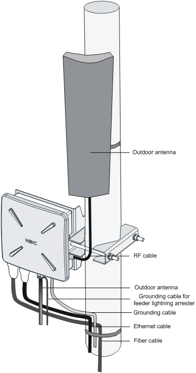
Connecting the Network
In practice, the AP can be connected to the Internet or a MAN through an Ethernet interface, as shown in Figure 4-23.
Figure 4-23 Connection between the AP and Internet (the AP works in the FAT AP mode)
![]()
A special outdoor waterproof Ethernet cable is required to connect the AP and waterproof treatment should be made to the Ethernet cable at the outlet of the chassis.
