| Title | Size | Downloads |
|---|---|---|
| 01-Text.pdf | 3.49 MB |
- Table of Contents
- Related Documents
-
| Title | Size | Download |
|---|---|---|
| 01-Text | 3.49 MB |
Interface Numbering for the WX3024
Interface Numbering for the WX3010
Interface Numbering for the WX3008
Installing the Device in a 19-inch Rack
Introduction to Mounting Brackets
Installing the Device Using Front Mounting Brackets
Installing the Device Using Front and Rear Mounting Brackets
Installing the Device Using Front Mounting Brackets and a Tray
Installing the Device Using Front Mounting Brackets and Slide Rails
Installing the Device on a Workbench
Connecting the Interface Cables
Connecting the Ethernet Cables
Installing and Removing Optional Interface Modules
4 Starting and Configuring the Device
Setting up a Configuration Environment
Connecting the Device to a Configuration Terminal
Approaches for Software Maintenance
Updating Software Through a Serial Connection
Modifying Serial Communication Parameters
Updating BootWare Through a Serial Connection
Updating Applications Through a Serial Connection
Updating Applications Using TFTP
Updating an Application Using TFTP Through the BootWare Menu
Updating and Backing Up an Application Using TFTP Through the CLI
Updating Applications Using FTP
Updating an Application Using FTP Through the BootWare Menu
Updating and Backing Up an Application Using FTP Through the CLI
Updating Web Files on the Switching Engine
Maintaining the Application and Configuration Files
Setting the Application File Type
Backing Up and Restoring BootWare
Backing Up and Restoring BootWare Through the BootWare Menu
Backing Up and Restoring BootWare Through the CLI
Troubleshooting Software Loading Failure
Troubleshooting the Power System
Troubleshooting the Configuration System
Introduction
The H3C WX3000 Series Unified Switches are networking products wholly developed by Hangzhou H3C Technologies Co., Ltd. (hereinafter referred to as H3C) that incorporate the functions of WLAN access controllers and Gigabit Ethernet switches. The WX3000 series unified switches include the WX3024, WX3010 and WX3008 unified switches (hereinafter referred to as the WX3000 series, WX3024, WX3010 and WX3008, respectively). The WX3000 series provides Gigabit ports, supports power over Ethernet plus (PoE+) and 802.11a/b/g/n series access points (APs), with the maximum output power of 25 W per port. Together with the Fit APs developed by H3C, the WX3000 series can implement wireless LAN (WLAN) deployments while providing rich data switching features. The WX3000 series is the ideal solution to the provisioning of integrated wireline and wireless access for small- and medium-sized enterprises and branches of large-sized enterprises.
Appearance
Figure 1-1 shows the appearance of the WX3024.
Figure 1-1 Appearance of the WX3024
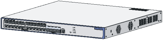
Figure 1-2 shows the appearance of the WX3010.
Figure 1-2 Appearance of the WX3010
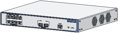
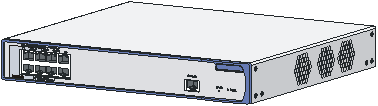
Figure 1-3 shows the appearance of the WX3008.
Figure 1-3 Appearance of the WX3008
Front Panel
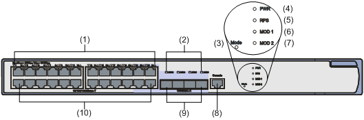
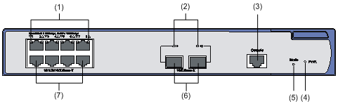
As shown in Figure 1-4, the front panel of the WX3024 provides twenty-four 10/100/1000Base-T Ethernet ports, four 1000Base-X SFP ports, and one console port.
Figure 1-4 Front panel of the WX3024
|
(1) LEDs of 10/100/1000 Base-T Ethernet ports |
(2) LEDs of 1000Base-X SFP ports |
|
(3) PoE/PoE+ LED (Mode) |
(4) Power status LED (PWR) |
|
(5) RPS LED (RPS) |
(6) Extension slot LED (MOD1) |
|
(7) Extension slot LED (MOD2) |
(8) Console port |
|
(9) 1000Base-X SFP ports |
(10) 10/100/1000 Base-T Ethernet ports |
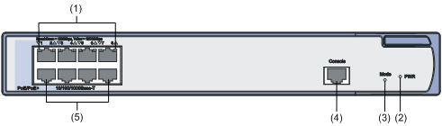
As shown in Figure 1-5, the front panel of the WX3010 provides eight 10/100/1000Base-T Ethernet ports, two 1000Base-X SFP ports, and one console port.
Figure 1-5 Front panel of the WX3010
|
(1) LEDs of 10/100/1000 Base-T Ethernet ports |
(2) LEDs of 1000Base-X SFP ports |
|
(3) Console port |
(4) Power status LED (PWR) |
|
(5) PoE/PoE+ LED (Mode) |
(6) 1000Base-X SFP ports |
|
(7) 10/100/1000 Base-T Ethernet ports |
|
As shown in Figure 1-6, the front panel of the WX3008 provides eight 10/100/1000Base-T Ethernet ports (among which only GigabitEthernet 1/0/1 through GigabitEthernet 1/0/4 support PoE) and one console port.
Figure 1-6 Front panel of the WX3008
|
(1) LEDs of 10/100/1000 Base-T Ethernet ports |
(2) Power status LED (PWR) |
|
(3) PoE/PoE+ LED (Mode) |
(4) Console port |
|
(5) 10/100/1000 Base-T Ethernet ports |
|
Rear Panel
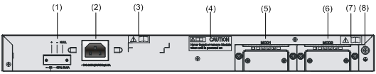
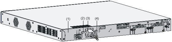
As shown in Figure 1-7, the rear panel of the WX3024 provides an AC power receptacle, a DC power receptacle, and two extension slots for 10 GE interface modules.
Figure 1-7 Rear panel of the WX3024
|
(1) DC power receptacle |
(2) AC power receptacle |
|
(3) OPEN BOOK mark |
(4) CAUTION mark |
|
(5) 10 GE port slot 1 |
(6) 10 GE port slot 2 |
|
(7) OPEN BOOK mark |
(8) Grounding screw |
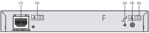
As shown in Figure 1-8, the rear panel of the WX3010 and WX3008 provides an AC power receptacle.
Figure 1-8 Rear panel of the WX3010
|
(1) AC power receptacle |
(2) OPEN BOOK mark |
|
(3) Grounding sign |
(4) Grounding screw |
|
(5) OPEN BOOK mark |
|
When seeing the OPEN BOOK and CAUTION marks, refer to relevant sections before performing the corresponding operations.
Table 1-1 Meanings of the OPEN BOOK mark
|
Operation |
Related section |
|
Connect the power cable |
|
|
Connect the ground cable |
|
|
Install optional interface modules |
System Specifications
Processor and Memory
Table 1-2 Processor and memory specifications
|
Item |
Specification |
|
Processor |
XLS208 (750 MHz) |
|
Flash memory |
64 MB |
|
Memory module type and size |
DDR2 SDRAM (512 MB) |
Dimensions and Weight
Table 1-3 Dimension and weight specifications
|
Device model |
Dimensions (H × W × D) |
Weight |
|
WX3024 |
43.6 × 440 × 429 mm (1.7 × 17.3 × 16.9 in.) |
7.2 kg (15.9 lb.) |
|
WX3010 |
43.6 × 300 × 269 mm (1.7 × 11.8 × 10.6 in.) |
2.9 kg (6.4 lb.) |
|
WX3008 |
43.6 × 300 × 269 mm (1.7 × 11.8 × 10.6 in.) |
2.9 kg (6.4 lb.) |
Fixed Interfaces and Slots
Table 1-4 Fixed interface and slot specifications
|
Item |
WX3024 |
WX3010 |
WX3008 |
|
Console interface |
1 console interface: 9600 bps to 115200 bps, (9600 bps by default) |
||
|
Ethernet ports |
24 × 10/100/1000 Base-T Ethernet ports |
8 × 10/100/1000 Base-T Ethernet ports |
8 × 10/100/1000 Base-T Ethernet ports |
|
SFP ports |
4 × 1000Base-X SFP ports. Each of these ports and the corresponding 10/100/1000Base-T Ethernet port numbered in the range of 21 to 24 form a Combo interface. |
2 × 1000Base-X SFP ports numbered 9 and 10. |
— |
|
Slots |
2 extension slots for 10 GE interface modules |
— |
— |
Power Input System
![]()
l The WX3024 supports several power input modes: AC input only, DC input only, and concurrently use of AC and DC inputs. When AC and DC inputs are used concurrently, they serve as backup for each other.
l The WX3010 and WX3008 support AC input only.
l Only an H3C-recommended redundancy power supply (RPS) unit can be used to provide DC input.
AC power supply
Table 1-5 AC power supply specifications
|
Item |
WX3024 |
WX3010 |
WX3008 |
|
Rated voltage range |
100 to 240 VAC, 50/60 Hz |
||
|
Maximum voltage range |
90 to 264 VAC, 47 to 63 Hz |
||
|
Maximum system power consumption (without external PoE devices) |
100 W |
50 W |
40 W |
|
Minimum power consumption |
220 V × 0.282 A = 63 W |
220 V × 0.165 A = 36.5 W |
220 V × 0.128 A = 28.2 W |
DC power supply
DC voltage range: –52 V to –55 V
PoE Power Supply
The WX3000 series supports Power over Ethernet (PoE) to provide –48 VDC supply to attached powered devices, such as IP phones, WLAN APs, security and Bluetooth APs, through twisted pair cables.
![]()
Only the H3C-recommended external PoE power supply can be used as the DC input, rather than the –48 VDC power supply of the equipment room, which may cause device damage.
l As a power sourcing equipment (PSE), the WX3000 series supports the IEEE 802.3af standard while being compatible with some PoE powered devices that do not comply with the 802.3af standard.
l The WX3000 series provides power supply through fixed electrical Ethernet ports, with the maximum power transmission distance of 100 meters (328.08 ft.).
l Each Ethernet port of the WX3000 series provides a maximum of 25 W output power to the attached PoE powered device. In the case of AC input, the maximum output power with full load of the WX3024 is 370 W, and that of the WX3010 and WX3008 is 125 W; in the case of RPS input, the maximum output power of the WX3024 is 25 W × 24 = 600 W (Note that the RPS output power should be at least 700 W).
Components
LEDs
Table 1-6 lists the support of the WX3000 series for LEDs.
Table 1-6 LEDs supported by the WX3000 series
|
LED |
WX3024 |
WX3010 |
WX3008 |
|
Power status LED (PWR) |
Supported |
Supported |
Supported |
|
PoE/PoE+ status LED (Mode) |
Supported |
Supported |
Supported |
|
RPS status LED (RPS) |
Supported |
Not supported |
Not supported |
|
Gigabit Ethernet port status LEDs |
Supported |
Supported |
Supported |
|
Gigabit SFP port status LEDs |
Supported |
Supported |
Not supported |
|
Extension slot status LEDs (MOD1 and MOD2) |
Supported |
Not supported |
Not supported |
Table 1-7 shows the description of the LEDs status
Table 1-7 Description of the LEDs status
|
LED |
Mark |
Status |
Description |
|
Power status LED (green/yellow/red) |
PWR |
Solid green |
The system is going through the power on self test (POST) or downloading software. |
|
Blinking green (1 Hz) |
The system is working normally. |
||
|
Solid red |
The system failed to pass the POST or has detected a serious fault. |
||
|
Solid yellow (1 Hz) |
At least one port has failed the POST or detected a minor fault. |
||
|
Off |
No AC input is present. |
||
|
PoE/PoE+ status LED (green/yellow) |
Mode |
Solid green |
The PoE/PoE+ is operational. |
|
Blinking green (3 Hz) |
PoE/PoE+ supply is not available because the maximum output power of the port is exceeded or the remaining power is insufficient. |
||
|
Solid yellow |
The ports cannot provide PoE/PoE+ supply due to an over-temperature, over-voltage, or under-voltage protection shutdown of the PoE/PoE+ system. |
||
|
Blinking yellow (3 Hz) |
At least one port failed to pass the POST; if the PoE sub-board is in position, it may be caused by a UART communication failure or some other self test failure. |
||
|
Off |
No PoE/PoE+ supply. |
||
|
RPS status LED (yellow/green) |
RPS |
Solid green |
Both AC and DC inputs are normal. |
|
Solid yellow |
The AC input is abnormal or no AC input is present, while the DC input is normal. |
||
|
Off |
No DC input is present. |
||
|
10/100/1000 Base-T Ethernet port status LED (yellow/green) |
— |
Solid green |
A 1000 Mbps link is present on the port. |
|
Blinking green (33 Hz) |
The port is receiving or transmitting data at 1000 Mbps. |
||
|
Solid yellow |
A 10/100 Mbps link is present on the port. |
||
|
Blinking yellow (33 Hz) |
The port is receiving or transmitting data at 10/100 Mbps. |
||
|
Blinking yellow (3 Hz) |
The port failed to pass the POST. |
||
|
Off |
No link is present on the port. |
||
|
Gigabit SFP port status LED (yellow/green) |
— |
Solid green |
A 1000 Mbps link is present on the port. |
|
Blinking green (33 Hz) |
The port is receiving or transmitting data at 1000 Mbps. |
||
|
Solid yellow |
A 100 Mbps link is present on port. |
||
|
Blinking yellow (33 Hz) |
The port is receiving or transmitting data at 100 Mbps. |
||
|
Blinking yellow (3 Hz) |
The port failed the POST. |
||
|
Off |
No link is present on the port. |
||
|
Extension slot LED (yellow/green) |
MOD1 (or MOD2) |
Solid green |
An extension module is present in the slot. |
|
Solid yellow |
The slot does not support the extension module installed in it. |
||
|
Blinking green |
The extension module is receiving or transmitting data. |
||
|
Blinking yellow |
The extension module failed the POST. |
||
|
Off |
No extension module is present in the slot or the extension module is not connected. |
Fixed Interfaces
Console port
The WX3000 series provides an RS-232 asynchronous serial console port, which can be used to connect a background terminal (a PC, for example) for system debugging, configuration, maintenance, management, and software loading.
As shown in Figure 1-9, the console cable is an 8-core cable with an RJ-45 connector at one end for the console port of the device, and a DB-9 female connector at the other end for the 9-pin serial port of the configuration terminal.
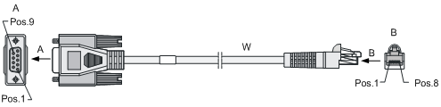
Table 1-8 Console cable pinouts
|
RJ-45 pin |
Signal |
Direction |
DB-9 pin |
|
1 |
RTS |
← |
7 |
|
2 |
DTR |
← |
4 |
|
3 |
TXD |
← |
3 |
|
4 |
CD |
→ |
1 |
|
5 |
GND |
— |
5 |
|
6 |
RXD |
→ |
2 |
|
7 |
DSR |
→ |
6 |
|
8 |
CTS |
→ |
8 |
Ethernet interfaces
1) Introduction
l The WX3024 provides twenty-four 10/100/1000Base-T Ethernet ports and four 1000Base-X SFP ports.
Each SFP port and the corresponding 10/100/1000Base-T Ethernet port jointly form a Combo interface. Only one of the two ports of a Combo interface can be used at a time. Table 1-9 lists the SFP and electrical Ethernet ports that form the Combo interfaces.
Table 1-9 SFP and electrical Ethernet ports of the WX3024 that form the Combo interfaces
|
1000Base-X SFP port |
10/100/1000Base-T Ethernet port |
|
25 |
22 |
|
26 |
24 |
|
27 |
21 |
|
28 |
23 |
l The WX3010 provides eight 10/100/1000Base-T Ethernet ports and two 1000Base-X SFP ports.
The electrical Ethernet ports support 10/100/1000 Mbps auto-sensing. The working modes of an Ethernet port at different speeds are shown in Table 1-10.
Table 1-10 Ethernet interface speeds and working modes
|
Interface speed |
Working mode |
|
10 Mbps (auto-sensing) |
Half/full duplex auto-negotiation |
|
100 Mbps (auto-sensing) |
Half/full duplex auto-negotiation |
|
1000 Mbps (auto-sensing) |
Full duplex auto-negotiation |
l The WX3008 provides eight 10/100/1000Base-T Ethernet ports.
The electrical Ethernet ports support 10/100/1000 Mbps auto-sensing. The working modes of an Ethernet port at different speeds are shown in Table 1-10.
The electrical Ethernet port status LEDs are above the RJ-45 sockets. The triangular pointer above each LED indicates which port the LED is for.
l The optical Ethernet ports of the WX3000 series support 100/1000 Mbps full duplex. The optical port status LEDs are above the 1000Base-X SFP ports, each indicating the status of the corresponding optical port.
![]()
The support for the speed of optical Ethernet ports depends on the model of the optical transceivers.
2) RJ-45 connectors
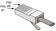
The 10/100/1000M electrical Ethernet ports of the WX3000 series work with Category-5 twisted pair cables with RJ-45 connectors, as shown in Figure 1-10.
3) LC connectors
As an indispensable passive component in a fiber communication system, a fiber connector is mainly used for the removable connection between optical tunnels. This facilitates the testing and maintenance of the optical system and makes optical inter-connections more flexible.
Currently, the WX3000 series supports only LC connectors.
Figure 1-11 LC connector

![]()
l When connecting a networking device using optical fibers, first make sure that the fiber connectors will work with the optical transceivers.
l Before connecting fiber cables, make sure that the optical power of the receiver end does not exceed the upper threshold of the receiving optical power of the optical transceiver; otherwise, the optical transceiver may be damaged. For the optical power specifications of the receiver end, refer to Appendix A.
Transceiver Modules
The WX3000 series supports the following optical transceivers:
Table 1-11 Description of optical transceivers
|
Item |
WX3024 |
WX3010 |
WX3008 |
|
SFP transceivers |
FE SFP transceivers |
Supports SFP-FE-SX-MM1310-A |
Not supported |
|
Supports SFP-FE-LX-SM1310-A |
|||
|
GE SFP transceivers |
Supports SFP-GE-SX-MM850-A |
||
|
Supports SFP-GE-LX-SM1310-A |
|||
|
GE BIDI transceivers |
Supports SFP-GE-LX-SM1310-BIDI |
||
|
Supports SFP-GE-LX-SM1490-BIDI |
|||
|
FE BIDI transceivers |
Supports SFP-FE-LX-SM1310-BIDI |
||
|
Supports SFP-FE-LX-SM1550-BIDI |
|||
|
XFP transceivers |
Supports XFP-SX-MM850 |
Not supported |
Not supported |
|
Supports XFP-LX-SM1310 |
|||
|
XENPAK modules |
Supports XENPAK-SX-MM850 |
Not supported |
Not supported |
|
Supports XENPAK-LX-SM1310 |
l Optical transceivers are optional components and are not supplied with the WX3000 series. Use H3C-recommended optical transceivers. For details about the technical specifications of SFP optical transceiver, refer to Appendix A.
l The WX3024 supports all XFP optical transceivers except those requiring –5.2 V power supply.
l The BIDI optical transceivers must be used in pairs. For example, if an SFP-GE-LX-SM1310-BIDI is used at one end, an SFP-GE-LX-SM1490-BIDI must be used at the other end. The same is true for FE BIDI modules.
RPS
When the AC power supply fails, an RPS unit can feed power to maintain the normal operation of the system.
![]()
l The WX3010 and WX3008 do not support the RPS unit.
l An RPS unit is an optional accessory to be separately orderly if needed.
l For the RPS unit installation information, refer to section Connecting the RPS Cable on page 3-19.
DC Power Cables
Table 1-12 Description of DC power cables
|
Item |
Length |
Description |
|
CAB-48V Pwr-2m-T2.5^2 |
2 m (6.56 ft.) |
14AWG power cable |
|
CAB-RPS Non PoE-2m-JD5 |
2 m (6.56 ft.) |
JD5 DC power cable |
|
CAB-RPS Non PoE-2m-JD5-A |
2 m (6.56 ft.) |
JD5-A DC power cable |
![]()
l The WX3010 and WX3008 do not support DC power input.
l DC power cables are optional accessories to be separately order if needed.
l The DC power cables should be shorter than 3 meters (9.84 ft.) to minimize voltage attenuation.
Fans
The WX3010 is equipped with three fans for heat dissipation of the whole system.
The WX3008 is equipped with three fans for heat dissipation of the whole system.
Interface Numbering
Interface Numbering for the WX3024
The WX3024 provides 29 fixed interfaces numbered GigabitEthernet 1/0/1 through GigabitEthernet 1/0/29, among which:
l GigabitEthernet 1/0/1 through GigabitEthernet 1/0/24: 10/100/1000 Base-T Ethernet ports, with the last part of the port numbers indicated on the front panel;
l GigabitEthernet 1/0/25 through GigabitEthernet 1/0/28: 1000Base-X SFP optical ports, with the last part of the port numbers indicated on the front panel;
l GigabitEthernet 1/0/29: a virtual interface for the connection between the access control engine and the switching engine.
The WX3024 provides two 10 GE interface module slots. The interfaces on the interface modules installed in these slots are numbered TenGigabitEthernet 1/1/1 and TenGigabitEthernet 1/2/1.
Interface Numbering for the WX3010
The WX3010 provides 11 fixed interfaces numbered GigabitEthernet 1/0/1 through GigabitEthernet 1/0/11, among which:
l GigabitEthernet 1/0/1 through GigabitEthernet 1/0/8: 10/100/1000 Base-T Ethernet ports, with the last part of the port numbers indicated on the front panel;
l GigabitEthernet 1/0/9 through GigabitEthernet 1/0/10: 1000Base-X SFP optical ports, with the last part of the port numbers indicated on the front panel;
l GigabitEthernet 1/0/11: a virtual interface for the connection between the access control engine and the switching engine.
Interface Numbering for the WX3008
The WX3008 provides nine fixed interfaces numbered GigabitEthernet 1/0/1 through GigabitEthernet 1/0/9, among which:
l GigabitEthernet 1/0/1 through GigabitEthernet 1/0/8: 10/100/1000 Base-T Ethernet ports, with the last part of the port numbers indicated on the front panel;
l GigabitEthernet 1/0/9: a virtual interface for the connection between the access control engine and the switching engine.
Safety Precautions
![]()
Installation and removal of the unit and its accessories must be carried out by qualified personnel. You must read all of the Safety Instructions supplied with your device before installation and operation.
![]()
Installation und Ausbau der Anlage und ihrer Zubehörteile müssen von qualifiziertem Personal realisiert werden. Sie müssen vor der Installation oder Bedienung allen beiliegenden Sicherheitshinweise lesen.
![]()
负责安装和日常维护本设备的人员必须具备安全操作基本技能。在操作本设备前,请务必认真阅读和执行产品手册规定的安全规范。
To avoid any device impairment and bodily injury caused by improper use, observe these rules:
l Pull the power plug(s) out of the device before cleaning the device. Do not clean the device using wet cloth or liquid.
l Keep the device away from water or dampness. Prevent water or moisture from entering the device chassis.
l Do not place the device on an unstable case or desk. The device might be damaged severely in case of a fall.
l Ensure proper ventilation in the equipment room and keep the vents of the device free of obstruction.
l Make sure that the operating voltage is within the range as labeled on the device.
l To avoid electrical shocks, do not open the chassis when the device is operating or when electrical hazards are present.
l When replacing interface modules, always wear an ESD-preventive wrist strap.
Installation Site Checking
The device is designed for indoor use. You can mount the device either in a rack or on a workbench, but make sure that:
l Adequate space is reserved at the air inlet and exhaust vents for heat dissipation.
l The rack or workbench has a good ventilation system.
l The rack is sturdy enough to support the device and its accessories.
l The rack or workbench is well grounded.
To ensure normal operation and a long service life of your device, install it in an environment that meets the following requirements.
Temperature and Humidity
The temperature and humidity in the equipment room must be kept within a proper range.
l Lasting high humidity may lead to bad insulation, electricity creepage, mechanical property changes, and corrosion.
l If the relative humidity is too low, captive screws may become loose as a result of contraction of insulation washers, and static electricity may be produced in a dry environment to interfere the circuits on the device.
l Lasting high temperatures accelerate the aging of insulation materials and thus significantly lower the reliability and service life of the device.
The temperature and humidity requirements for the WX3000 series are listed in Table 2-1.
|
Item |
Specification |
|
Temperature |
0°C to 45°C (32°F to 113°F) |
|
Relative humidity |
5% to 95% (noncondensing) |
Cleanliness
Dust is hazardous to the operating safety of the device. Dust buildup on the chassis may result in static adsorption, causing poor contact of metal connectors or metal contact points. When the relative indoor humidity is low, especially, electrostatic adsorption is more likely to happen. This not only shortens the service life of your device but also causes communication failures. The following table lists the dust concentration limit in the equipment room.
Table 2-2 Dust concentration limit in the equipment room
|
Physical active substance |
Limit (particles/m3) |
|
Dust particles |
≤ 3 × 10⁴ (No visible dust on the tabletop over three days) |
|
Note: The dust particle diameter is ≥ 5 μm |
|
In addition, the equipment room should also meet the rigorous limits on salts, acids, and sulfides to eliminate corrosion and premature aging of some parts. Table 2-3 lists the limits on harmful gases in the equipment room.
Table 2-3 Limit on harmful gases in the equipment room
|
Gas |
Limit (mg/m3) |
|
SO2 |
0.2 |
|
H2S |
0.006 |
|
NH3 |
0.05 |
|
Cl2 |
0.01 |
ESD Prevention
Static electricity generation and harms
The electrostatic induction that adversely affects the operation of the device mainly comes from:
l Outdoor electric fields caused by high-voltage power lines or lightning strikes.
l Internal systems, such as the indoor environment, floor materials, and the structure of the integrated equipment.
Although a great deal of electrostatic discharge (ESD) prevention considerations have been taken in the design of the WX3000 series, excessive static electricity is still remarkably harmful to the whole device.
ESD prevention methods
To prevent ESD damage, do the following:
l Make sure that the device and the floor are well grounded.
l Keep the equipment room clean.
l Keep proper temperature and humidity conditions.
l When touching a circuit board, always wear ESD-preventive gloves or an ESD-preventive wrist strap, and wear antistatic work clothes.
l When mounting, removing, observing, or moving an interface module, always take the printed circuit board (PCB) by the edges without touching the components on the PCB.
l After removing an interface module, place the PCB on an antistatic workbench with the component-side facing upward or place it in an antistatic bag.
ESD-preventive wrist strap
![]()
The ESD-preventive wrist strap is not provided with the device.
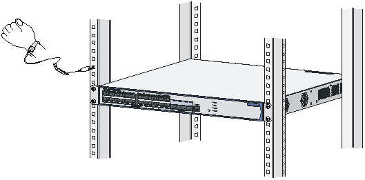
Follow these steps to use an ESD-preventive wrist strap:
Step1 Put on and fasten the wrist strap and make sure the wrist strap has good skin contact.
Step2 Attach grounding wire to the wrist strap and the alligator clip to the rack.
Step3 Verify that the rack is well grounded.
Figure 2-1 Wear an ESD-preventive wrist strap
EMI Prevention
All interference sources, from the outside or inside of the device and application system, adversely affect the device in the conduction patterns of capacitance coupling, inductance coupling, electromagnetic wave radiation, and common impedance (including grounding system) coupling, and cable conduction (including power cables, signal cables and output cables). To prevent interference, do the following:
l Use a TN system for the system earthing of the AC power supply, and use a single-phase three-wire AC socket with a protection earth (PE) to effectively filter interference from the power grid.
l Keep the device away from high-power radio transmitters, radars, and high-frequency heavy-current devices.
l Take electromagnetic shielding measures when necessary. For example, use shielded interface cables.
l Route the interface cables only indoors to protect signal interfaces against over-voltage or over-current conditions cause by lightning strikes.
Laser Safety
The WX3000 series is the Class 1 laser product.
Do not look directly at any working optical transceivers on the WX3000 series because the high-energy laser beam emitted from the optical fiber may hurt your eyes.
![]()
Staring into the laser beam emitted from an optical fiber may hurt your eyes.
Installation Tools
Flat-blade screwdrivers
Philips screwdrivers: P2-150 mm
EDS-preventive wrist straps
![]()
3 Installing the Device
![]()
When you ask your sales agent to maintain your device, make sure that the dismantlement-preventive seal of H3C on a mounting screw of the device chassis is intact. If you want to open the chassis, you should contact the agent for permission. Otherwise, you will bear any consequence resulting from your actions.
Installing the Device in a 19-inch Rack
The WX3000 series can be installed in a standard 19-inch rack, and the installation falls into the following four scenarios:
l Installing the device with front mounting brackets.
l Installing the device with front and rear mounting brackets.
l Installing the device with front mounting brackets and a tray.
l Installing the device with front mounting brackets and slide rails.
Refer to Table 3-1 for the installation scenarios supported by the device models.
Table 3-1 Installation scenarios supported by the WX3024 and WX3010
|
Device Model |
Front mounting brackets |
Front and rear mounting brackets |
Front mounting brackets and a tray |
Front mounting brackets and slide rails |
|
WX3024 |
Not supported |
Supported |
Supported |
Supported |
|
WX3010 |
Supported |
Not supported |
Supported |
Not supported |
|
WX3008 |
Supported |
Not supported |
Supported |
Not supported |
![]()
l If the width of the device is more than 300 mm (11.8 in.), the front mounting brackets can be used only for fixing the device, rather than weight-bearing.
l The slide rails provided by H3C are suitable only for H3C standard racks with the depth of 1000 mm (39.37 in.). You need to seek other supporting means if your rack has a different depth.
Introduction to Mounting Brackets
Appearance of a front mounting bracket
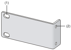
Figure 3-1 Front mounting bracket of the WX3024
|
(1) Screw holes for fixing the front mounting bracket onto the rack (using M6 screws) |
(2) Screw hole for fixing the front mounting bracket to the device chassis |
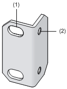
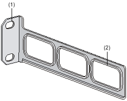
Figure 3-2 Front mounting bracket of the WX3010 and WX3008
|
(1) Screw holes for fixing the front mounting bracket onto the rack (using M6 screws) |
(2) Screw hole for fixing the front mounting bracket to the device chassis |
![]()
The front mounting bracket of the device needs to be separately installed if needed for the installation scenario selected in Table 3-1.
Appearance of a rear mounting bracket
Figure 3-3 Rear mounting bracket of the WX3024
|
(1) Screw holes for fixing the rear mounting bracket onto the rack (using M6 screws) |
(2) Heat dissipation holes |
Introduction to Slide Rails
![]()
The slide rails are optional components that need to be separately ordered if needed for the installation scenario selected in Table 3-1.
Appearance of a slide rail
Figure 3-4 A slide rail
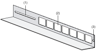
|
(1) Slot hole for fixing the slide rail onto the rear bracket of the rack. It allows adjustment of the device mounting screw position according to the device position. |
|
(2) Heat dissipation holes. Holes for heat dissipation between the device and the rack. |
|
(3) Slot hole for fixing the slide rail onto the front bracket of the rack. |
Installing the Device Using Front Mounting Brackets
Follow these steps to install the device (take the WX3010 for example) using front mounting brackets:
Step1 Put on an ESD-preventive wrist strap and verify that the rack is sturdy and properly grounded.
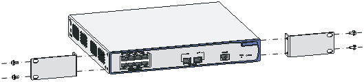
Step2 As shown in Figure 3-5, use the screws packed with the front mounting brackets to fix the front mounting brackets on the device.
Figure 3-5 Attach the front mounting brackets to the device
Step3 As shown in Figure 3-6, determine the device installation position in the rack and use screws and cage nuts to fix the front mounting brackets on the front square-holed brackets of the rack.
Figure 3-6 Attach the front mounting brackets to the rack
|
(1) Front square-holed bracket |
(2) Front mounting bracket |
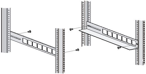
Installing the Device Using Front and Rear Mounting Brackets
Follow these steps to install the device using front and rear mounting brackets:
Step1 Put on an ESD-preventive wrist strap and verify that the rack is sturdy and properly grounded.
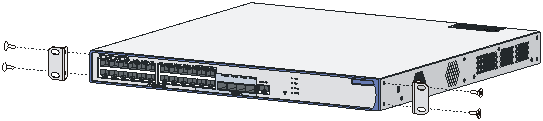
Step2 As shown in Figure 3-7, use the screws packed with the front mounting brackets to fix the front mounting brackets on both sides of the device.
Figure 3-7 Attach the front mounting brackets to both sides of the device
Step3 As shown in Figure 3-8, fix the weight-bearing screws packed with the rear mounting brackets on both sides of the device.
Figure 3-8 Install the weight-bearing screws
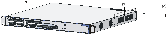
|
(1) Three holes for mounting the weight-bearing screw (select one as needed) |
(2) Weight-bearing screw |
![]()
There are three holes on each side of the device for the weight-bearing screws. You can select a proper location as needed. The rear mounting brackets will support the weight of the device through firm contact with the weight-bearing screws.
Step4 As shown in Figure 3-9, determine the device installation position in the rack and use screws and cage nuts to fix the rear mounting brackets on the rear square-holed brackets of the rack.
Figure 3-9 Install rear mounting brackets
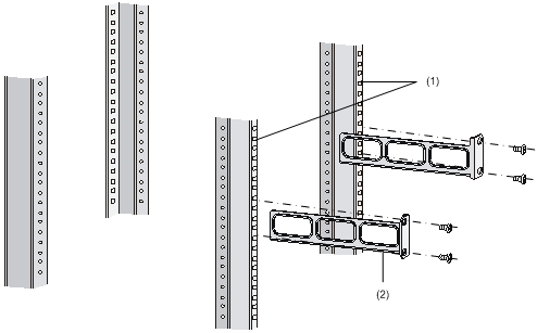
|
(1) Rear square-holed brackets |
(2) Rear mounting bracket |
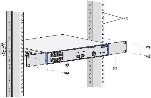
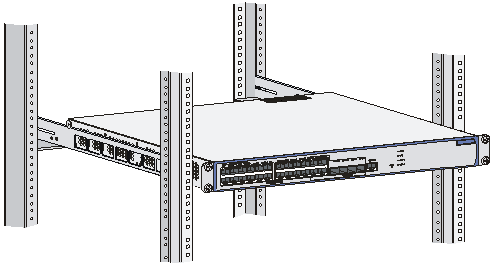
Step5 Hold the bottom of the device with one hand and the front part with the other hand, and gently push the device into the rack, as shown in Figure 3-10.
Figure 3-10 Install the device using front and rear mounting brackets (1)
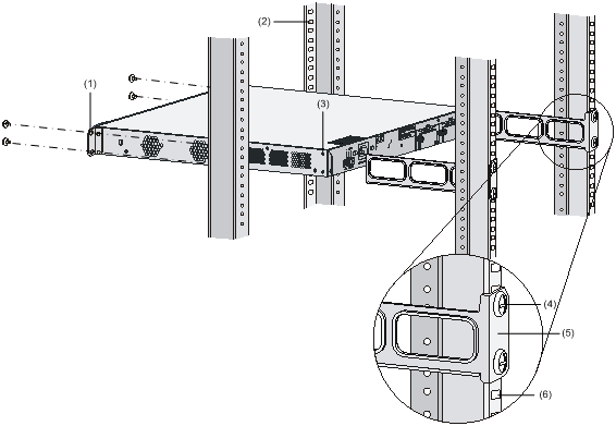
|
(1) Front mounting bracket |
(2) Front square-holed bracket |
|
(3) Weight-bearing screw |
(4) Screw for fixing the rear mounting bracket onto the rear square-holed bracket |
|
(5) Rear mounting bracket |
(6) Rear square-holed bracket |
![]()
After pushing the device into the rack, make sure that the upper edges of the rear mounting brackets fixed on the rack have close contact with the weight-bearing screws on the device, as shown in Figure 3-11.
Figure 3-11 Install the device using front and rear mounting brackets (2)
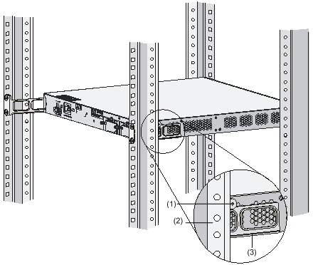
|
(1) Rear square-holed bracket |
|
|
(3) Rear mounting bracket |
|
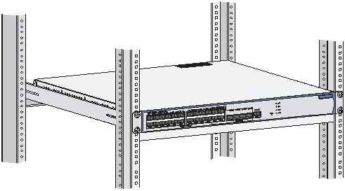
Step6 Fix the front mounting brackets on the front square-holed brackets of the rack with screws and cage nuts. Make sure that the device is firmly fixed on the rack through the front and rear mounting brackets, as shown in Figure 3-12.
Figure 3-12 Install the device using front and rear mounting brackets (3)
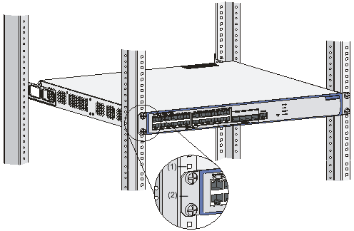
|
(1) Front square-holed bracket |
Installing the Device Using Front Mounting Brackets and a Tray
![]()
The tray is an optional component that needs to be separately ordered if needed.
Follow these steps to install the device (take the WX3024 as example) in a rack using front mounting brackets and a tray:
Step1 Put on an ESD-preventive wrist strap and check that the rack is sturdy and properly grounded.
Step2 As shown in Figure 3-7, use the screws packed with the front mounting brackets to fix the front mounting brackets on both sides of the device.
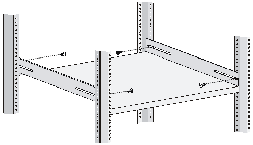
Step3 Fix the tray on the rack as shown in Figure 3-13 (this figure is for reference only and may differ from the actual installation on your rack).
Step4 Place the device horizontally on the tray, push it into the rack along the tray, and fix the front mounting brackets onto the front square-holed brackets of the rack using the screws and cage nuts, as shown in Figure 3-14.
Figure 3-14 Install the device using front mounting brackets and a tray

Installing the Device Using Front Mounting Brackets and Slide Rails
Installing a device with front mounting brackets and slide rails
Follow these steps to install the device with front mounting brackets and slide rails:
Step1 Put on an ESD-preventive wrist strap and verify that the rack is sturdy and properly grounded.
Step2 As shown in Figure 3-7, use the screws packed with the front mounting brackets to fix the front mounting brackets on both sides of the device.
Step3 Fix the slide rails on both sides of the rack with M5 self-tapping screws as shown in Figure 3-15 (this figure is for reference only and may differ from the actual installation on your rack).
Figure 3-15 Install slide rails
Step4 Hold the device by both sides of it and gently push it into the rack along the slide rails, as shown in Figure 3-16. Verify that the bottom of the device is in firm contact with the slide rails.
Figure 3-16 Install the device using front mounting brackets and slide rails (1)
Step5 Fix the front mounting brackets on the front square-holed brackets of the rack using the M6 screws and cage nuts. Make sure that the device is firmly fixed on the rack through the front mounting brackets and slide rails, as shown in Figure 3-17.
Figure 3-17 Install the device using front mounting brackets and slide rails (2)
![]()
You are recommended to keep a distance of 1 U (44.45 mm/1.75 in.) between two devices to ensure good heat dissipation.
Installing the Device on a Workbench
Without a standard 19-in rack, you can install the device on a clean workbench. During the installation, make sure that:
l The workbench is sturdy and well grounded.
l The workbench is a well-ventilated environment. Keep at least 10 cm (3.94 in.) clearance around the device for heat dissipation.
l No heavy object is placed on the device.
l At least 15 mm (0.59 in.) distance is provided between two devices when they are stacked one above the other.
Wall Mounting
You can mount the WX3010 and WX3008 on concrete walls or wood walls.
Introduction to screw and wall anchor
Figure 3-18 and Figure 3-19 show the recommended sizes (in millimeters) of screws and wall anchor used for mounting.
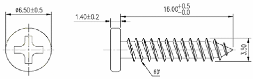
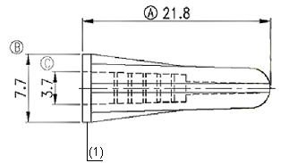
|
(1) Outside edge of wall anchor |
Installation procedure
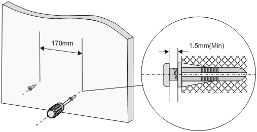
Follow these steps to mount the device on the wall:
Step1 As shown in Figure 3-20, drill two holes with a diameter of 5 mm (0.2 in.) across in the wall on the same horizontal line, with a distance of 170 mm (6.69 in.).
![]()
Drill two holes according to the sizes of wall anchors and screws so that wall anchors could go into the holes, only the edges could remain outside the wall, and the screws could be fixed on the wall tightly.
Step2 Insert wall anchors into the holes and keep only the edges outside the wall.
Step3 Drive screws into the wall anchors, keeping the inside of screw head at least 1.5 mm (0.06 in) away from the edge of the wall anchor so that the device could hang on the screws securely.
Figure 3-20 Mount the device on the wall
Step4 Align the two installation holes at the bottom of the device with these two screws to hang the device.
![]()
When mounting the device, keep the Ethernet ports of the device facing downwards and the two sides with ventilation holes vertical to the ground.
Magnet Mounting
The WX3010 and WX3008 can be installed using magnet mounting.
Introduction to magnetic accessories
Magnetic accessories consists of four permanent magnets and four M3*6 countersunk head screws, as shown in Figure 3-21.
Figure 3-21 Magnets and countersunk head screws
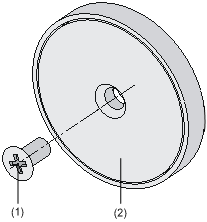
|
(1) M3*6 countersunk head screw |
(2) Permanent magnet |
Installation procedure
Follow these steps to complete magnet mounting:
Step1 As shown in Figure 3-22, use a Phillips screwdriver to pass the countersunk head screw through the round hole at the center of the permanent magnet, fasten it to a blind nut in the dent of the device bottom, and ensure that the permanent magnet and the device are fastened reliably.
![]()
Remove the cushion, if any, from the dent before installation.
Step2 Attach the magnet-mounted device to the specified location. Do not to get your fingers stuck between because the magnetism is very huge.
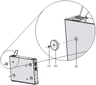
|
(1) M3*6 countersunk head screw |
(2) Permanent magnet |
|
(3) Blind nut in the dent of the device bottom |
|
![]()
l Select the installation location carefully. In the case of poor surface, magnet mounting may not be reliable.
l Put the device at a stable place free from vibrations or shocks. Otherwise, personal injuries or equipment damage may occur.
l Avoid installing the device at a high place because personal injuries or equipment damage may occur in case of a falloff.
l Avoid frequently moving the desk-mounted device because such movements may damage the surface coating.
l Keep the front panel of the device facing downwards and the two sides with ventilation holes vertical to the ground, if you want to install the device vertically.
l Pay attention that the weight of external cables should not bring about a falloff, which may result in personal injuries or equipment damage.
l Keep floppy disks and magnetic cards away from magnets to avoid erasure of any information.
l Keep computers and monitors that are easily influenced by magnetic fields away from magnets. Otherwise, faults may occur to these electronic devices.
l The power cords may vary with different standards of different countries, so you may need to select a bail latch as needed.
Connecting the Ground Cable
![]()
The correct connection of the protection ground cable of the device is an essential safeguard against lightning strokes and interference. You must correctly connect the ground cable before using your device.
The power input end of the device has a noise filter, whose central ground is directly connected with the chassis, forming the protection ground (PGND) of the chassis. This chassis ground must be securely earthed so that the induction and creepage currents can be safely discharged to the earth to enhance the anti-EMI capability of the device. The following describes how to connect the PGND cable in different situations.
If a grounding strip is available
Attach one end of the yellow-green PGND cable of the device to the grounding screw on the chassis and the other end to the grounding terminal on the grounding strip and fasten the nut.
Figure 3-23 Connect the PGND cable when a grounding strip is available
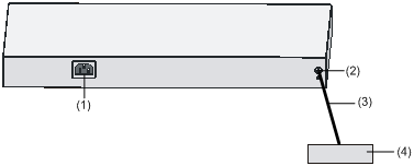
|
(1) AC power receptacle |
(2) Grounding screw |
|
(3) PGND cable |
(4) Grounding strip in the equipment room |
![]()
The fire main and the lightning rod of the building are not good grounding options. The PGND cable of the device should be connected to the earthing system of the equipment room.
Without a grounding strip
1) If an area with exposed earth is available nearby where a grounding conductor can be buried
Hammer a 0.5 m (1.64 ft.) or longer angle iron or steel tube longer into the earth. Weld the yellow-green grounding cable to the angle iron or steel tube, and treat the joint for corrosion protection.
Figure 3-24 Connect the PGND cable to a buried grounding conductor
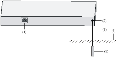
|
(1) AC power receptacle |
(2) Grounding screw |
|
(3) PGND cable |
(4) Earth ground |
|
(5) Angle iron |
|
2) If it is not allowed to bury a ground conductor
l If the device is AC powered, you can ground it through the PE wire of the AC power supply. Make sure that the PE wire is well grounded in the power distribution room or on the AC transformer side.
Figure 3-25 Ground the device through the AC PE wire
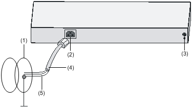
|
(1) Power transformer |
(2) AC power receptacle |
|
(3) Grounding screw |
(4) Three-core AC power cable |
|
(5) PE wire |
|
l If the device is –48 VDC powered, you can ground it through the return wire (RTN) of the DC power supply. Make sure that the RTN wire is well grounded at the DC output of the DC power cabinet.
Figure 3-26 Ground the device through the PGND of a power cabinet
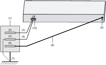
|
(1) AC/DC power cabinet |
(2) –48 V busbar |
|
(3) -48 V |
(4) RTN busbar |
|
(5) RTN |
(6) PGND busbar |
|
(7) Earth ground |
(8) PGND cable |
|
(9) Grounding screw |
(10) DC power receptacle |
![]()
The WX3010 and WX3008 do not support DC power input.
Connecting the Power Cables
Connecting AC Power Cable
![]()
The power cords may vary with different standards of different countries, so you may need to select a bail latch as needed.
Follow these steps to connect the AC power cable:
Step1 Verify that the chassis PGND is correctly connected to the earth ground.
Step2 Install the bail latch onto the device and pivot the bail latch up.
Step3 Plug one end of the power cable to the AC power receptacle on the rear panel of the chassis and plug the other end to the AC power source.
Step4 Place the bail latch over the AC power cable to secure the plug in place.
Figure 3-27 Connect the AC power cable
|
(1) Rear panel |
(2) Bail latch holder |
|
(3) Bail latch |
(4) AC power cable |
Step5 Check the RPS LED on the front panel of the device. Solid green indicates that the AC power input is normal.
![]()
l Since the WX3010 and WX3008 do not have the RPS LED, blinking green of the PWR LED indicates that the AC power input is normal. For details about LED status, refer to LEDs on page 1-6.
l The bail latch prevents the power cable from accidentally falling off.
Connecting the RPS Cable
![]()
The WX3010 and WX3008 do not support RPS.
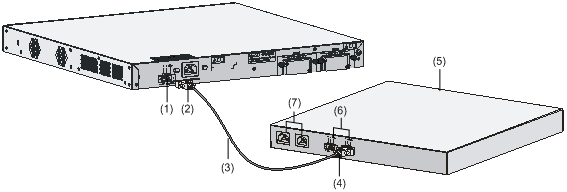
Follow these steps to connect the RPS cable:
Step1 Check that the device is powered off and the RPS unit is switched off.
Step2 Use a Philips screwdriver to remove the screws on the cover on the DC power receptacle and take off the cover.
Step3 Connect the RPS cable to the DC power receptacle on the chassis.
Step4 Turn the strain release screws on the RPS cable clockwise so that the RPS cable plug is firmly seated in the DC power receptacle, and then fasten the strain release screws.
Step5 Connect the other end of the RPS cable to an output interface of the RPS unit.
Figure 3-28 Connect the RPS cable
|
(1) DC power receptacle |
(2) RPS cable plug for the DC power receptacle |
|
(3) RPS cable |
(4) RPS cable plug for the RPS output |
|
(5) RPS unit |
(6) Output interfaces of the RPS unit |
|
(7) AC power input interfaces of the RPS unit |
|
Step6 Check the RPS LED on the front panel of the device. LED ON means the RPS unit is correctly connected.
![]()
l The RPS unit is an optional accessory. The WX3024 supports the RPS1000.
l Check that the ground cable is properly connected before powering on the device.
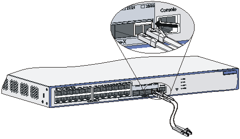
Connecting the Interface Cables
Connecting the Console Cable
1) Prepare a configuration terminal
The configuration terminal can be an ASCII terminal with an RS232 serial port or a PC. The description in this section assumes that you use a PC as the configuration terminal.
2) Connect the console cable
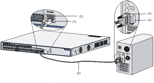
Power off the device, plug the DB-9 female connector of the console cable to the serial port of the PC that will be used to configure your device, and connect the RJ-45 connector of the console cable to the console port of the device.
![]()
Pay attention to the mark on the console port and be sure to plug the connector into the right port.
Figure 3-29 Connect the console cable
|
(1) RJ-45 connector |
(2) Console port |
|
(3) DB-9 female connector |
(4) Serial port on the configuration terminal |
|
(5) Console cable |
|
![]()
If the device has been powered on:
l When connecting the console cable, first connect the DB-9 connector to the PC before connecting the RJ-45 connector to the device.
l When removing the console cable connection, first unplug the RJ-45 connector from the device and then unplug the DB-9 connector from the PC.
Connecting the Ethernet Cables
Connecting an electrical Ethernet port
Follow these steps to connect an electrical Ethernet port:
Step1 Connect one end of the Ethernet cable to the electrical Ethernet port on the device and the other end to an Ethernet interface of the peer device.
Step2 After powering on the device, check the LEDs of the fixed electrical Ethernet port. For details about the LED description, refer to Table 1-7.
Connecting an optical Ethernet interface
Follow these steps to connect a 100/1000 Mbps optical interface:
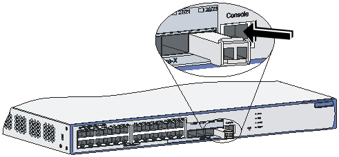
Step1 Point the end of the optical transceiver without a release lever toward the SFP transceiver socket, verify that the optical transceiver is not positioned upside down, and gently insert it into the socket.
Figure 3-30 Insert an optical transceiver
Step2 Identify the Rx and Tx ports on the optical transceiver and plug the two LC connectors at one end of the fibers into the Rx and Tx ports and the LC connectors at the other end of the fiber into respectively the Tx and Rx ports of an optical interface on the peer device.
Figure 3-31 Connect fiber connectors
Step3 After powering on the device, check the LEDs of the SFP interfaces. For details about the SFP LEDs, refer to Table 1-7.
Installing and Removing Optional Interface Modules
![]()
l The WX3010 and WX3008 do not support installing interface modules.
l The interface modules and inner optical modules of the WX3024 are not hot swappable.
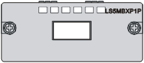
XFP Interface Modules
Introduction
10-Gigabit small form-factor pluggable (XFP) modules are used for electrical-to-optical and optical-to-electrical conversion in optical signal transmission. An XFP transceiver requires fiber cables with LC connectors.
Front panel of an XFP interface module
Figure 3-32 Front panel of an XFP interface module
Installing an XFP interface module
Step1 Put on an ESD-preventive wrist strap and verify that the wrist strap is properly grounded. Then, take the XFP interface module out of the package.
Step2 Loosen the captive screws on blank panel covering an extension slot on the rear panel of the device and remove the blank panel.
Step3 Take the XFP interface module by the captive screws on the front panel, and push the XFP interface module steadily into the slot along the slide rails until it is firmly seated in the device.
Figure 3-33 Install an XFP interface module
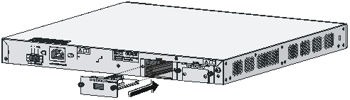
Step4 Fasten the captive screws on the XFP module to secure it in place.
![]()
l Keep the removed blank panel properly for future use.
l Do not over-tighten the captive screws on the front panel of the interface module.
Removing an XFP interface module
Step1 Put on an ESD-preventive wrist strap and check that the wrist strap is properly grounded.
Step2 Use a Philips screwdriver to loosen the captive screws on the front panel of the XFP interface module.
Step3 Pull the XFP interface module toward you until it is completely out of the device chassis.
![]()
When installing or removing an optional interface module, pay attention to the following points:
l Do not use excessive force in the operation and do not touch the surface-mounted components directly with your hands.
l After removing an optional module, if the slot is to remain empty, install a blank panel to prevent dust and ensure normal ventilation in the device.
XENPAK Module
Introduction
The 10-Gigabit Ethernet transceiver package (XENPAK) module provides the optical-to-electrical and electrical-to-optical conversion function and multiple signal processing functions.
Front panel of an XENPAK module
Figure 3-34 Front view of an XENPAK module

Installing an XENPAK module
Step1 Put on an ESD-preventive wrist strap and verify that the wrist strap is properly grounded. Then, take the XENPAK module out of the package.
Step2 Loosen the screws on the cover plate in the middle of the blank panel covering an extension slot on the rear panel of the device with a screwdriver and remove the cover plate.
![]()
When installing an XENPAK module, you only need to remove the small cover plate in the middle of the blank panel instead of removing the entire blank panel.
Step3 Take the XENPAK module by the screws on the front panel and steadily push the module into the slot along the slide rails until it is firmly seated in the device.
Figure 3-35 Install an XENPAK module
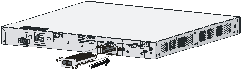
Step4 Fasten the screws on the XENPAK module to secure it in place.
![]()
l Keep the removed cover plate properly for future use.
l Do not over-tighten the screws on the XENPAK module.
l XENPAK modules are hot-pluggable on the device.
Removing an XENPAK module
Step1 Put on an ESD-preventive wrist strap and verify that the wrist strap is properly grounded.
Step2 Loosen the captive screws on the XENPAK module with a flat-blade screwdriver.
Step3 Pull the XENPAK module toward you until it is completely out of the device chassis.
![]()
When installing or removing an optional module, pay attention to the following points:
l Do not use excessive force during the operation and do not touch the surface-mounted components directly with your hands.
l After removing a module, if the slot is to remain empty, install a blank panel to prevent dust and ensure normal ventilation in the device.
Installation Verification
During the installation of the device, always verify the installation before powering on the device:
l The power supply system meets the device requirements.
l The ground cable is correctly connected.
l Both the console cable and power cables are correctly connected.
Setting up a Configuration Environment
Connecting the Device to a Configuration Terminal
For details of connecting a device to a configuration terminal, refer to section Connecting the Console Cable on page 3-20.
Setting Terminal Parameters
Before configuring your device through a console terminal, a PC running Microsoft Windows XP for example, you need to set some parameters for the console terminal to communicate with the device. Follow these steps to set the terminal parameters:
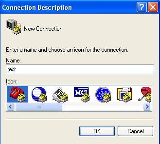
Step1 Start the PC and select Start > Programs > Accessories > Communications > HyperTerminal. The Connection Description dialog box appears, as shown below. Type the name for the new connection and click OK.
Figure 4-1 Connection description interface
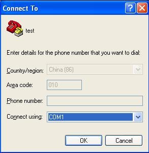
Step2 In the Connect To dialog box, select the serial port to be used for local configuration from the Connect using drop-down list, as shown below. Make sure the serial port is the one actually connected with the console port of the device. Then, click OK.
Figure 4-2 Select the serial port for local configuration
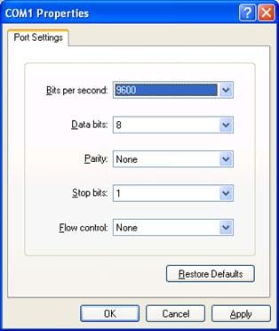
Step3 Set the serial port parameters as shown below.
Set the properties of the serial port in the COM1 Properties dialog box, as shown in Table 4-1.
Table 4-1 Set serial port parameters
|
Item |
Value |
|
Bits per second |
9600 bps (default) |
|
Data bits |
8 |
|
Parity |
None |
|
Stop bits |
1 |
|
Flow control |
None |
Figure 4-3 Set serial port parameters
![]()
To restore the default settings, click Restore Defaults.
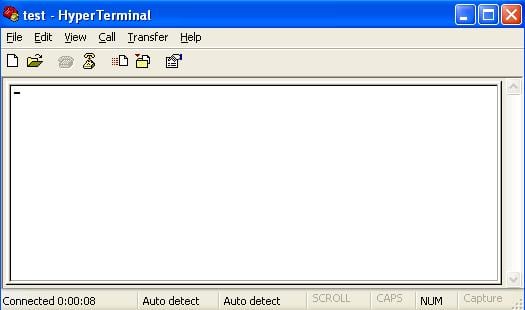
Step4 After setting the serial port parameters, click OK to enter the HyperTerminal window.
Figure 4-4 HyperTerminal window
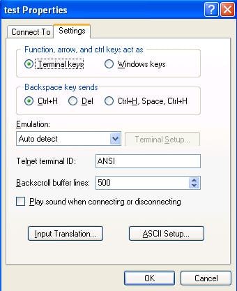
Step5 Configure the properties of the HyperTerminal. Select File > Properties, and click the Settings tab. Select VT100 or Auto detect from the Emulation drop-down list box and click OK.
Figure 4-5 Set the terminal emulation
Powering On the Device
Verifying Before Power-On
Before powering on the device verify that:
l The power cable and ground cable are properly connected.
l The power supply voltage is within the range labeled on the device.
l The console cable is properly connected, the configuration terminal to be used for configuration is running, and the terminal parameters have been set.
Boot Process
After being powered on, the device (take the WX3024 as an example) first implements memory initialization and then runs the extended program of BootWare. The following system information is output on the terminal:
System is starting...
Booting Normal Extend BootWare....
The Extend BootWare is self-decompressing.................
Done!
***************************************************************************
* *
* H3C WX3024 BootWare, Version 1.10 *
* *
***************************************************************************
Copyright (c) 2004-2009 Hangzhou H3C Technologies Co., Ltd.
Compiled Date : Apr 27 2009
CPU Type : XLS208
CPU L1 Cache : 32KB
CPU Clock Speed : 750MHz
Memory Type : DDR2 SDRAM
Memory Size : 512MB
Memory Speed : 533MHz
BootWare Size : 512KB
Flash Size : 64MB
CPLD Version : 004
PCB Version : Ver.A
Press Ctrl+B to enter extended boot menu...
You can press Ctrl + B to enter the extended Boot menu; otherwise, the system will start loading and decompressing the application file.
![]()
l To enter the Boot menu, you must press Ctrl + B within 4 seconds when the system prompts “Press Ctrl+B to enter extended boot menu”.
l You need to restart the device if you want to enter the Boot menu after the application files are decompressed.
l For easy reading and understanding, the extended Boot menu is referred to as the BootWare main menu if not otherwise specified in this document.
Starting to get the main application file--flash:/main.bin!............................
............................................
The main application file is self-decompressing ........................................
......................................................................................
......................................................................................
......................................................................................
......................................................................................
......................................................................................
......................................................................................
......................................................................................
......................................................................................
......................................................................................
......................................................................................
.............................
Done!
The ANP application file is self-decompressing..........................................
......................................................................................
......................................................................................
......................................................................................
......................................................................................
..........................................................................
Done!
System application is starting...
User interface aux0 is available.
Press ENTER to get started.
After you press Enter, the following prompt is displayed:
<System>
This indicates that the system has entered user view, and you can configure the device now.
![]()
During the startup process, the CPLD will be automatically upgraded to the latest version, if any. The system will display “The board cpld update successfully, please repower device.” after the upgrade process. At this prompt, power off and restart the device so that the new CPLD version takes effect.
![]()
Because the display information of the WX3010, WX3024 and WX3008 are similar, this chapter takes the WX3024 as an example.
Introduction
Files Managed by the Device
The WX3000 series consists of two virtual systems: access control engine and switching engine, for which two independent file systems are employed to manage the following four types of files:
l BootWare program file
l Application files
l Configuration files
l Web files
The access control engine manages the BootWare program file and application files; the switching engine manages the Web files; both the access control engine and switching engine store and manage their respective configuration files.
BootWare Program File
The BootWare program file is used to boot applications during the startup of the device. A complete BootWare program file includes a basic section and an extended section.
l The basic BootWare section is used to complete the primary initialization of the system.
l With rich human-computer interaction (HCI) functions, the extended BootWare section is used for initializing the interfaces and updating the applications and the boot system.
l A complete BootWare program is the combination of the basic and extended BootWare sections. After the basic BootWare section is started, you can download and update the extended BootWare through the menu of the basic BootWare section.
![]()
Do not power off or restart the device when updating the BootWare program file; otherwise, the BootWare program may be damaged and the device may fail to operate normally.
Application Files
The WX3000 series supports the Dual Image function. By default, the system defines three application files for system boot:
l Main application file (referred to as main file)
l Backup application file (referred to as backup file)
l Secure application file (referred to as secure file)
These three application files are stored in the flash memory, with the file name extension of .bin.
Typically, the default application files are written into the built-in flash memory before device delivery.
If you have uploaded all the three types of application files in the flash memory, the system uses these three files to boot the device in the sequence of main.bin, backup.bin, and secure.bin. For how to set the type of an application file, refer to section Maintaining the Application and Configuration Files on page 5-22.
The following gives the default names and types of the application files and their priorities for booting:
l Main application file. The default name is main.bin and the file type is M. it is the default application file for system boot.
l Backup application file. The default name is backup.bin and the file type is B. If the system fails to boot using the main application file, it tries the backup application file.
l Secure application file. The default name is secure.bin and the file type is S. If the system fails to boot using the backup application file, it tries the secure application files. If the system fails to boot using the secure file, it gives a startup failure message.
Note that:
l Only the application files of the M, B, and S types can be used to boot the system, while an application file of the N type (an application file other than the M, B, or S type) cannot.
l You can rename the application files in the flash memory through the command line interface (CLI) after the application program is loaded. You can modify the file type of the M, B, and N types application files through the BootWare menu or the CLI after application startup, while you cannot modify the file type of the S-type application file.
l The secure application file is the last resort for system boot; therefore, you cannot change the file type of the secure application file or turn another type of file into a secure file by modifying the file type. The secure file can only be downloaded from the BootWare menu.
l Only one file of the same type (M, B, or S) can exist in the flash memory at a time. For example, if an application file of type M+B exists in the CF card, another file of type M or B cannot exist. If the type of another file is changed to B, the existing type M+B file changes to a file of type M.
Configuration Files
With the file name extension of .cfg, configuration files are used to store the configuration information of the device. Typically, no configuration file with the name extension .cfg is provided when the device is delivered (a configuration file with name extension .def is provided by the switching engine). In this case, the device loads the default configuration at startup. If the configuration file is deleted or missing, the device also loads the default configuration at reboot.
l The access control engine has only one configuration file with no backup.
l The switching engine has main and backup configuration files, which are managed like the application files on the access control engine.
![]()
l The length of a configuration file name must not exceed 64 characters (including the drive identifier and the string terminator). For example, if the drive identifier is flash: /, the maximum length of a file name is [ 64 – 1 – 5 ] = 58 characters.
l If the length of a file name exceeds 58 characters, operations on that file will fail. It is recommended to keep a file name within 16 characters.
l There is a limitation on the length of file name that can be displayed in BootWare. If a file name is shorter than 30 characters, all the characters of the file name can be displayed; if a file name has or exceeds 30 characters, only the first 26 characters of the file name can be displayed, followed by a tilde (~) and a serial number. This serial number identifies the position in sequence of the file. For example, if file A, file B and file C have a file name longer than 30 characters, the name of file A will appear as the first 26 characters plus ~001, that of file B will appear as the first 26 characters plus ~002, and that of file C will appear as the first 26 characters plus ~003.
Web Files
Web files are used by the switching engine to provide Web-based functions, and are released with version releases (each version has a default Web file). You are not recommended to modify the file name and settings.
Web files fall into main and backup files, and are managed like the application files on the access control engine.
Approaches for Software Maintenance
You can maintain the device in either of the following two ways:
l Update BootWare and application files using the XMODEM protocol through a serial port.
l Update BootWare and application files using the TFTP/FTP protocol via an Ethernet port through the BootWare menu or the CLI.
![]()
l The BootWare program is updated together with the Comware application. When you update the Comware application to the latest version, the BootWare is updated to the latest version automatically.
l Before updating the software, check the current version of BootWare and that of the application program to make sure that the correct file is used for the update. For the association between the host software version and the BootWare version, refer to the hardware and software compatibility matrix in Release Notes.
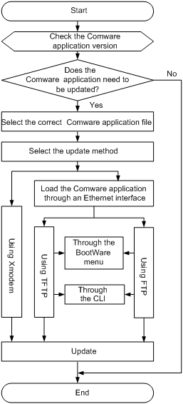
Software Update Flow
Figure 5-1 BootWare and application update flow
BootWare Menus
BootWare Main Menu
When a device is powered on or restated, the terminal first displays the following information:
System is starting...
Then the following information appears:
Booting Normal Extend BootWare....
The Extend BootWare is self-decompressing.................
Done!
***************************************************************************
* *
* H3C WX3024 BootWare, Version 1.10 *
* *
***************************************************************************
Copyright (c) 2004-2009 Hangzhou H3C Technologies Co., Ltd.
Compiled Date : Apr 27 2009
CPU Type : XLS208
CPU L1 Cache : 32KB
CPU Clock Speed : 750MHz
Memory Type : DDR2 SDRAM
Memory Size : 512MB
Memory Speed : 533MHz
BootWare Size : 512KB
Flash Size : 64MB
CPLD Version : 004
PCB Version : Ver.A
Press Ctrl+B to enter extended boot menu...
You can press Ctrl + B to enter the extended Boot menu; otherwise, the system will start loading and decompressing the application file.
![]()
l To enter the Boot menu, you must press Ctrl + B within 4 seconds when the system prompts “Press Ctrl+B to enter extended boot menu”.
l You need to restart the device if you want to enter the Boot menu after the application files are decompressed.
Press Ctrl + B when the system prompts “Press Ctrl+B to enter extended boot menu”. Then, the system prompts you to enter the BootWare password:
Please input BootWare password:
Enter the BootWare password. The system displays the BootWare main menu.
![]()
l The initial BootWare password is null.
l If you fail to enter the correct password three times in a row, the system will be halted and all you can do is to restart the system.
Note: The current operating device is flash
Enter < Storage Device Operation > to select device.
=============================<EXTEND-BOOTWARE MENU>============================
|<1> Boot System |
|<2> Enter Serial SubMenu |
|<3> Enter Ethernet SubMenu |
|<4> File Control |
|<5> Modify BootWare Password |
|<6> Skip Current System Configuration |
|<7> BootWare Operation Menu |
|<8> Clear Super Password |
|<9> Storage Device Operation |
|<0> Reboot |
================================================================================
Enter your choice(0-9):
BootWare Submenus
Serial submenu
Select 2 from the BootWare main menu to enter the serial submenu. The following information is displayed:
=============================<Enter Serial SubMenu>============================
|Note:the operating device is flash |
|<1> Download Application Program To SDRAM And Run |
|<2> Update Main Application File |
|<3> Update Backup Application File |
|<4> Update Secure Application File |
|<5> Modify Serial Interface Parameter |
|<0> Exit To Main Menu |
===============================================================================
Enter your choice(0-5):
Ethernet submenu
Select 3 from the BootWare main menu to enter the Ethernet submenu. The following information is displayed:
============================<Enter Ethernet SubMenu>===========================
|Note:the operating device is flash |
|<1> Download Application Program To SDRAM And Run |
|<2> Update Main Application File |
|<3> Update Backup Application File |
|<4> Update Secure Application File |
|<5> Modify Ethernet Parameter |
|<0> Exit To Main Menu |
|<Ensure The Parameter Be Modified Before Downloading!> |
===============================================================================
Enter your choice(0-5):
File control submenu
Select 4 from the BootWare main menu to enter the file control submenu. The following information is displayed:
=================================<File CONTROL>================================
|Note:the operating device is flash |
|<1> Display All File(s) |
|<2> Set Application File type |
|<3> Delete File |
|<0> Exit To Main Menu |
===============================================================================
Enter your choice(0-3):
BootWare operation submenu
Select 7 from the BootWare main menu to enter the BootWare operation submenu. The following information is displayed:
===========================<BootWare Operation Menu>===========================
|Note:the operating device is flash |
|<1> Backup Full BootWare |
|<2> Restore Full BootWare |
|<3> Update BootWare By Serial |
|<4> Update BootWare By Ethernet |
|<0> Exit To Main Menu |
===============================================================================
Enter your choice(0-4):
Storage device operation submenu
Select 9 from the BootWare main menu to enter the storage device operation submenu. The following information is displayed:
================================<DEVICE CONTROL>===============================
|<1> Display All Available Nonvolatile Storage Device(s) |
|<2> Set The Operating Device |
|<3> Set The Default Boot Device |
|<0> Exit To Main Menu |
===============================================================================
Enter your choice(0-3):
Updating Software Through a Serial Connection
Introduction to XMODEM
To update BootWare and applications through a serial connection, use the XMODEM protocol.
XMODEM is a file transfer protocol that is widely applied due to its simplicity and good performance. XMODEM transfers files through serial ports. It supports two types of data packets (128 bytes and 1 KB), two check methods (general checksum and CRC), and error packet retransmission mechanism (generally the maximum number of transmission attempts is ten).
The XMODEM transmission procedure is completed by the cooperation of a receiving program and a sending program. The receiving program sends a negotiation packet to negotiate the packet check method. After the negotiation, the sending program starts to send data packets. When receiving a complete packet, the receiving program checks the packet using the agreed method.
l If the check succeeds, the receiving program sends an acknowledgement (ACK) character and the sending program proceeds to send another packet.
l If the check fails, the receiving program sends a negative acknowledgement (NAK) character and the sending program retransmits the packet.
Modifying Serial Communication Parameters
Sometimes, we need a high serial port baud rate to save the update time, or a lower baud rate to ensure the transmission reliability. This section introduces how to adjust the serial communication baud rate.
Enter the BootWare main menu, select 2 to enter the serial submenu, and then select 5 to modify the baud rate. The system displays the following:
=================================<BAUDRATE SET>============================
|Note:'*'indicates the current baudrate |
| Change The HyperTerminal's Baudrate Accordingly |
|---------------------------<Baudrate Available>---------------------------|
|<1> 9600(Default)* |
|<2> 19200 |
|<3> 38400 |
|<4> 57600 |
|<5> 115200 |
|<0> Exit |
===========================================================================
Enter your choice(0-5):
Select an appropriate downloading rate. If you want to a 115200 bps download rate, for example, enter 5. Then the system displays the following information:
Baudrate has been changed to 115200 bps.
Please change the terminal's baudrate to 115200 bps, press ENTER when ready.
Now that the serial communication baud rate of the device has been changed to 115,200 bps while that of the terminal is still 9,600 bps, the two sides cannot communicate with each other. Change the baud rate to 115,200 bps in HyperTerminal.
Disconnect the terminal connection in HyperTerminal, as shown below:
Figure 5-2 Disconnect the terminal connection
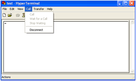
Select File > Properties. In the Properties dialog box, click Configure… and then select 115,200 from the Bits per second drop-down list box.
Figure 5-3 Modify the baud rate

Select Call > Call to reestablish the connection.
Figure 5-4 Reestablish the connection
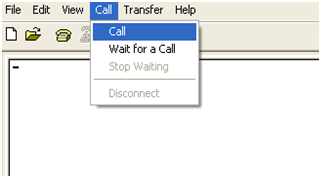
Then, press Enter in the terminal window. The terminal displays the current baud rate setting:
The current baudrate is 115200 bps
===============================<BAUDRATE SET>=============================
|Note:'*'indicates the current baudrate |
| Change The HyperTerminal's Baudrate Accordingly |
|---------------------------<Baudrate Available>--------------------------|
|<1> 9600(Default)* |
|<2> 19200 |
|<3> 38400 |
|<4> 57600 |
|<5> 115200 |
|<0> Exit |
==========================================================================
Enter your choice(0-5):
![]()
After downloading files with a changed baud rate, timely change the baud rate back to 9,600 bps in HyperTerminal to ensure the normal display on the terminal screen when the system boots or reboots.
Updating BootWare Through a Serial Connection
Enter the BootWare main menu (refer to section BootWare Main Menu on page 5-4) and select 7 to enter the BootWare operation submenu. For details about this submenu, refer to section BootWare operation submenu on page 5-7.
Select 3 from the BootWare operation submenu to enter the BootWare operation serial submenu:
======================<BOOTWARE OPERATION SERIAL SUB-MENU>=====================
|<1> Update Full BootWare |
|<2> Update Extend BootWare |
|<3> Update Basic BootWare |
|<4> Modify Serial Interface Parameter |
|<0> Exit To Main Menu |
===============================================================================
Enter your choice(0-4):
You need to modify the serial interface baud rate to accelerate the file update. Select 4 from the BootWare operation serial submenu and then modify the serial interface baud rate to 115200 bps. Moreover, you need to set the baud rate to the same value on the configuration terminal to ensure communication between both sides. For how to modify the baud rate, refer to section Modifying Serial Communication Parameters on page 5-8.
Select 0 to return to the BootWare operation submenu.
======================<BOOTWARE OPERATION SERIAL SUB-MENU>=====================
|<1> Update Full BootWare |
|<2> Update Extend BootWare |
|<3> Update Basic BootWare |
|<4> Modify Serial Interface Parameter |
|<0> Exit To Main Menu |
===============================================================================
Enter your choice(0-4):
Select 1 from the BootWare operation submenu. The following information appears:
Please Start To Transfer File, Press <Ctrl+C> To Exit.
Waiting ...CCCCCCCCCCCCCCCCCCCCCCCCCCCCCCC
Select Transfer > Send file in the HyperTerminal window. The following dialog box appears.
Figure 5-5 File transmission dialog box
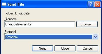
Click Browse to select the application file to be downloaded, select Xmodem from the Protocol drop-down list, and click Send. The following dialog box appears:
Figure 5-6 Sending the application file using XMODEM
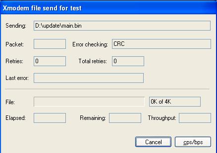
After download completion, the terminal displays the following information:
Download successfully!
19189956 bytes downloaded!
Updating Basic BootWare? [Y/N]Y
Updating Basic BootWare................Done!
Updating Extend BootWare? [Y/N]Y
Updating Extend BootWare..............Done!
Change the baud rate from 115200 bps back to 9600 bps in HyperTerminal and reboot the device.
![]()
l The file name, size and path shown in the figures are for reference only and may differ from the actualities on your device. Before updating the software of your device, check the current BootWare version and application version to make sure that the correct file is used for the update.
l After downloading files with a changed baud rate, timely change the baud rate back to 9,600 bps in HyperTerminal to ensure the normal display on the terminal screen when the system boots or reboots.
Updating Applications Through a Serial Connection
To update an application file through a serial connection, you need to enter the serial submenu. Select 2 from the BootWare main menu to enter the serial submenu. For details about this submenu, refer to section Serial submenu on page 5-6.
You can modify the serial interface baud rate to accelerate the file update. For details, refer to section Modifying Serial Communication Parameters on page 5-8. Select 2 from the serial submenu. The following information appears:
Please Start To Transfer File, Press <Ctrl+C> To Exit.
Select and send the appropriate application file in HyperTerminal. The procedure for updating an application file through a serial connection is the same as updating the BootWare program. For details, refer to section Updating BootWare Through a Serial Connection on page 5-10.
![]()
Typically, the size of an application program is over 10 MB. Even at a serial baud rate of 115,200 bps, the update takes about 30 minutes. Therefore, you are recommended to update an application program through an Ethernet port.
Updating Applications Using TFTP
To update a large application file, use the Trivial File Transfer Protocol (TFTP), which can remarkably shorten the software maintenance time.
TFTP is a TCP/IP protocol used for file transfer between client and server. It provides a simple and low-overhead file transfer service. TFTP provides unreliable data transfer over UDP and does not provide any access authorization and authentication mechanism. It employs the timeout retransmission method to implement best-effort delivery of data.
The WX3000 series provides TFTP Client service. That is, with the device serving as the TFTP client and the file server serving as the TFTP server, you can upload application files from the device to the file server, or download application files from the file server to the device.
You can update an application file using TFTP through either the BootWare menu or the CLI.
Updating an Application Using TFTP Through the BootWare Menu
Setting up an update environment
Figure 5-7 Set up a TFTP environment
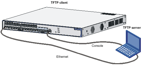
Step1 Connect the Ethernet interface GigabitEthernet 1/0/1 of the device to the PC using a crossover Ethernet cable, and configure IP addresses for the Ethernet interface of the device and the PC, which must be on the same network segment so that the device and the PC can communicate with each other. For example, set the IP address of the VLAN interface to 192.168.0.1 and that of the PC to 192.168.0.2.
Step2 Run TFTP Server on the PC, and set the path of the application file to be downloaded.
![]()
l The TFTP server software is not provided with the WX3000 series. You must make sure that it is available by yourself.
l On the WX3000 series, only the management Ethernet interface, namely GigabitEthernet 1/0/1 can be used for application update.
Configuring the Ethernet interface parameters
Before updating an application file through the management Ethernet interface, you need to configure the interface as follows:
Select 3 from the BootWare main menu to enter the Ethernet submenu and select 5 to enter the Ethernet interface configuration submenu.
============================<ETHERNET PARAMETER SET>===========================
|Note: '.' = Clear field. |
| '-' = Go to previous field. |
| Ctrl+D = Quit. |
===============================================================================
Protocol (FTP or TFTP) :tftp
Load File Name :main.bin
Target File Name :main.bin
Server IP Address :192.168.0.2
Local IP Address :192.168.0.1
Gateway IP Address :
FTP User Name :
FTP User Password :
![]()
When configuring a parameter, you can enter a new value directly, or press Enter to accept the default value that follows a colon. You can type . to clear the current input, - to return to the previous parameter field, and Ctrl+D to quit from the parameter configuration interface.
Updating an application file
After configuring the Ethernet interface parameters, select 3 from the BootWare main menu to enter the Ethernet submenu and then select 2. In this example you update the main application file. The following information appears:
Loading...............................................................................
......................................................................................
.................................Done!
19189956 bytes downloaded!
Updating File flash:/main.bin.........................................................
......................................................................................
......................................................................................
......................................................................................
......................................................................................
......................................................................................
......................................................................................
......................................................................................
.................................................................Done!
Finalizing application update
Select 0 to return to the BootWare main menu, and then press 1 to reboot the system.
![]()
l If you specify a filename that already exists in the flash memory, the system prompts The file is exist,will you overwrite it? [Y/N] If you select Y, the existing file will be overwritten.
l Make sure that sufficient space is available in the flash memory. In case of insufficient space, the update cannot proceed and the system will give an error prompt.
l The new application file replaces the existing file of the same type, if any, and becomes the only application file of that type. In this example, main.bin replaces the application file with the attribute of M and becomes the only main application file.
l For details about the file types, refer to Introduction on page 5-1.
Updating and Backing Up an Application Using TFTP Through the CLI
The access control engine and the switching engine have separate file systems. You need to log in to the CLI of a specific system before you can do file operations in it.
After the device starts, you are directly logged in to the access control engine system. To enter the switching engine system, use the oap connect slot 0 command; to log out, press Ctrl + K.
![]()
l The application files are managed only on the access control engine.
l On the CLI of the access control engine, you can change to the CLI for the switching engine through the oap command and perform operations on the configuration files and Web files on the switching engine.
Setting up an update environment
Set up a software update environment and specify the working path of the server. For details, refer to section Setting up an update environment on page 5-13.
l For operations on the access control engine, the data needs to be transferred from the switching engine to the access control engine; therefore, you need to configure the IP addresses of the switching engine, access control engine and the PC to be in the same network segment. For example, configure the IP address of the TFTP server as 192.168.0.1, that of the access control engine of the device as 192.168.0.2, and that of the switching engine as 192.168.0.3 (to configure the IP address of the switching engine, you need to change to CLI of the switching engine by using the oap command). Verify the connection by using the ping command.
l For operations on the switching engine, you need to log in to the switching engine using the oap command, configure the IP addresses as mentioned above, and verify the connection by using the ping command.
![]()
The IP addresses of the access control engine and switching engine are both configured in VLAN interface view.
Backing up and restoring application and configuration files
After setting up the environment, do the following on the terminal:
Use the dir command to check what files are in the file system:
<System>dir
Directory of flash:/
0 -rw- 855 Jul 26 2007 08:22:56 startup.cfg
1 -rw- 19189956 Jul 28 2035 10:35:38 main.bin
60884 KB total (41991 KB free)
<System>
For example, to copy the file startup.cfg on the device and save it as config.bak on the TFTP server, use the following command:
<System>tftp 192.168.0.1 put startup.cfg config.bak
File will be transferred in binary mode
Sending file to remote TFTP server. Please wait... \
TFTP: 855 bytes sent in 0 second(s).
File uploaded successfully.
To download config.cfg from the server to the device, use the following command:
<System>tftp 192.168.0.1 get config.cfg statup.cfg
The file statup.cfg exists. Overwrite it?[Y/N]:y
Verifying server file...
Deleting the old file, please wait...
File will be transferred in binary mode
Downloading file from remote tftp server, please wait...\
TFTP: 855 bytes received in 0 second(s)
File downloaded successfully.
If a file with the same name exists on the device, the device will prompt you whether to overwrite the existing file. You can choose Y to overwrite it or N to abort.
![]()
l When you back up a file to the server, the existing file with the same name on the server, if any, will be replaced without a prompt.
l The operations mentioned above are to be performed in user view.
l You can modify the backup configuration file with a text editor and then download the modified file to update the configuration. The update takes effect upon system reboot. Likewise, you can download the application file to the device and overwrite the existing main application file to update the application.
Updating Applications Using FTP
If the application file to be downloaded has a large size, you can use the File Transfer Protocol (FTP) to save the software maintenance time.
FTP is an application-layer TCP/IP protocol used for file transfer between a server and a client. It provides reliable, connection-oriented data transfer service over TCP.
You can update an application using FTP in two ways:
l Through the BootWare menu. In this approach, the device must serve as an FTP client.
l Through the CLI. In this approach, the device can serve as either an FTP server or an FTP client.
Updating an Application Using FTP Through the BootWare Menu
Setting up an update environment
Figure 5-8 Set up an environment, with the device as an FTP client

l Connect the Ethernet interface GigabitEthernet 1/0/1 of the device to the PC using a crossover Ethernet cable, and configure IP addresses for the Ethernet interface of the device and the PC, which must be on the same network segment so that the device and the PC can communicate with each other. For example, set the IP address of the VLAN interface to 192.168.0.1 and that of the PC to 192.168.0.2.
l Run the FTP Server on the PC and set the path of the application file to be downloaded, FTP username and password.
![]()
l The FTP server software is not provided with the WX3000 series. You must make sure that it is available by yourself.
l On the WX3000 series, only the management Ethernet interface, namely GigabitEthernet 1/0/1 can be used for application update.
For the rest steps, refer to section Configuring the Ethernet interface parameters on page 5-14, section Updating an application file on page 5-15, and section Finalizing application update on page 5-15.
Updating and Backing Up an Application Using FTP Through the CLI
With the device as an FTP client and the PC as an FTP server
1) Set up an update environment by referring to section Updating an Application Using FTP Through the BootWare Menu on page 5-18.
l For operations on the access control engine, the data needs to be transferred from the switching engine to the access control engine; therefore, you need to configure the IP addresses of the switching engine, access control engine and the PC to be in the same network segment. For example, configure the IP address of the FTP server as 192.168.0.1, that of the access control engine of the device as 192.168.0.2, and that of the switching engine as 192.168.0.3 (to configure the IP address of the switching engine, you need to change to CLI of the switching engine by using the oap command). Verify the connection by using the ping command.
l For operations on the switching engine, you need to log in to the switching engine using the oap command, configure the IP addresses as mentioned above, and verify the connection by using the ping command.
2) Maintain the device through the terminal connected to the console port of the device.
<System>ftp 192.168.0.1
Trying 192.168.0.1 ...
Press CTRL+K to abort
Connected to 192.168.0.1.
220 FTP service ready.
User(192.168.0.1:(none)):guest // Enter the username set on the server
331 Password required for quest.
Password: // Enter the password
230 User logged in
[ftp]
After a successful connection, you can execute the following commands to maintain the device.
Use the get and put commands to implement file download and backup.
[ftp]get main.bin main.bin // Download the file from the server to the device
flash:/main.bin has been existing. Overwrite it?[Y/N]:y
227 Entering passive mode (192,168,0,1,6,231).
125 Using exiting data connection………………
226 Closing data connection; File transfer successful.
FTP: 19189956 byte(s) received in 93.156 second(s) 206.00K byte(s)/sec.
[ftp]put main.bin main.bin // Back up the file from the device to the server
227 Entering passive mode (192,168,0,1,6,233).
125 Using exiting data connection
226 Closing data connection; File transfer successful.
FTP: 19189956 byte(s) sent in 21.417 second(s) 896.00Kbyte(s)/sec.
[ftp]quit
221 Service closing control connection
With the device as an FTP server and the PC acting as an FTP client
1) Set up an update environment
Figure 5-9 Set up an environment, with the device as an FTP server
l For operations on the access control engine, the data needs to be transferred from the switching engine to the access control engine; therefore, you need to configure the IP addresses of the switching engine, access control engine and the PC to be in the same network segment. For example, configure the IP address of the FTP client as 192.168.0.1, that of the access control engine of the device as 192.168.0.2, and that of the switching engine as 192.168.0.3 (to configure the IP address of the switching engine, you need to change to CLI of the switching engine by using the oap command). Verify the connection by using the ping command.
l For operations on the switching engine, you need to log in to the switching engine using the oap command, configure the IP addresses as mentioned above, and verify the connection by using the ping command.
2) Enable the FTP server
The FTP server feature supports concurrent access of multiple clients. Upon receiving a request from an FTP client, the FTP server performs the requested operation and returns the result. Use the following command to enable FTP server:
[System]ftp server enable
% Start FTP server
Add an authorized FTP username and password:
[System]local-user guest // Create user account guest
[System-luser- guest]service-type ftp // Set the user type to FTP
[System-luser- guest]password simple 123456 // Set the password to 123456
3) Maintain the device
After enabling FTP server and setting the username and password on the device, start the FTP client application on the PC. This example assumes that you use Microsoft FTP Client provided in Windows XP.
Open a DOS prompt window, and enter ftp at the DOS prompt.
C:\Documents and Settings\Administrator>ftp
ftp> // The system prompt changed to ftp>
ftp> open 192.168.0.2 // Connect to the device
Connected to 192.168.0.2.
220 FTP service ready.
User (192.168.0.2:(none)): guest // Enter the username set on the device
331 Password required for guest
Password: // Enter the password 123456
230 User logged in.
To back up main.bin from the device to the PC, use the following command:
ftp> binary // Set the transfer mode to binary mode
200 Type set to I.
ftp> lcd c:\temp // Change the local file directory
Local directory now C:\temp.
ftp> get main.bin main.bin // Back up the file from the device to the PC
200 Port command okay.
150 Opening BINARY mode data connection for /main.bin.
226 Transfer complete.
ftp: 19189956 bytes received in 22.53Seconds 851.87Kbytes/sec.
To restore the backup to the device, use the following command:
ftp> put main.bin main.bin
200 Port command okay.
150 Opening BINARY mode data connection for main.bin.
226 Transfer complete.
ftp: 19189956 bytes sent in 11.09Seconds 1727.37Kbytes/sec.
ftp> quit
221 Server closing.
Updating Web Files on the Switching Engine
If the application program is successfully upgraded and the switching engine has upgraded Web files, the Web files are automatically upgraded after the system reboots (manual upgrade is not recommended). During the starting process of the switching engine, the device searches files with the suffix of .web in the file system. Such Web files are named h3c-http3.1.9-000X.web, in which X varies with versions. If no such a file is available in the file system, the device loads it from the application program file package. After the system is rebooted, the Web file in the file system is displayed as follows:
<System>dir
Directory of unit1>flash:/
1 (*b) -rw- 957976 Apr 02 2000 00:44:15 h3c-http3.1.9-0001.web
2 -rw- 296 Apr 01 2000 23:56:03 config.def
3 (*) -rw- 729 Apr 01 2000 23:59:21 startup.cfg
6858 KB total (5917 KB free)
(*) -with main attribute (b) -with backup attribute
(*b) -with both main and backup attribute
Maintaining the Application and Configuration Files
You can modify the types of the files on the access control engine and view the file information through the file control submenu or the CLI.
![]()
You can maintain the files on the switching engine only through the CLI, rather than the BootWare menu.
Select 4 from the BootWare main menu to enter the file control submenu. The following information is displayed:
=================================<File CONTROL>================================
|Note:the operating device is flash |
|<1> Display All File(s) |
|<2> Set Application File type |
|<3> Delete File |
|<0> Exit To Main Menu |
===============================================================================
Enter your choice(0-3):
Displaying All Files
Displaying all files through the BootWare menu
Select 1 from the file control submenu. The following information appears:
Display all file(s) in flash:
'M' = MAIN 'B' = BACKUP 'S' = SECURE 'N/A' = NOT ASSIGNED
==============================================================================
|NO. Size(B) Time Type Name |
|1 19189956 Aug/08/2008 20:00:00 M flash:/main.bin |
|2 855 Aug/08/2008 20:00:00 N/A flash:/startup.cfg |
==============================================================================
Displaying all files in the CLI
<System>dir
Directory of flash:/
0 -rw- 19189956 Apr 27 2009 13:21:20 main.bin
1 -rw- 855 Nov 27 2061 11:07:24 startup.cfg
54610 KB total (29377 KB free)
Setting the Application File Type
Setting the application file type in the BootWare menu
Select 2 from the file control submenu. The following information appears:
'M' = MAIN 'B' = BACKUP 'S' = SECURE 'N/A' = NOT ASSIGNED
==============================================================================
|NO. Size(B) Time Type Name |
|1 19189956 Aug/08/2008 20:00:00 M flash:/main.bin |
|0 Exit |
==============================================================================
Enter file No:
Enter the file number at the prompt above. In this example, type 1 for main.bin, and press Enter. The system prompts you to specify a new file type:
Modify the file attribute:
==============================================================================
|<1> +Main |
|<2> -Main |
|<3> +Backup |
|<4> -Backup |
|<0> Exit |
==============================================================================
Enter your choice(0-4)
Select 1 to set the file type to M, 2 to remove the current M type, 3 to set the file type to B, and 4 to remove the current B type. For detailed description of the file types, refer to section Application Files on page 5-2.
Setting the application file type through the CLI
# Change the type of main.bin from B to M+B.
<System> boot-loader file main.bin main
This command will set the boot file. Continue? [Y/N]:y
The specified file will be used as the main boot file at the next reboot!
Deleting a File
Deleting a file through the BootWare menu
Select 3 from the file control submenu. The following information appears:
Deleting the file in flash:
'M' = MAIN 'B' = BACKUP 'S' = SECURE 'N/A' = NOT ASSIGNED
==============================================================================
|NO. Size(B) Time Type Name |
|1 19189956 Aug/08/2008 20:00:00 M flash:/main.bin |
|2 855 Aug/08/2008 20:00:00 N/A flash:/startup.cfg |
|0 Exit |
==============================================================================
Enter file No:
Enter the file number and press Enter. The following information appears:
The file you selected is flash:/startup.cfg,Delete it? [Y/N]
Press Y to proceed. When the following information appears, the file has been successfully deleted:
Deleting..........Done!
Deleting a file through the CLI
You can use the delete [ /unreserved ] file-url command in user view to delete a file.
l /unreserved: Deletes the file immediately without placing it into the Recycle Bin.
l file-url: Name of the file to be deleted.
# Delete test.txt from the root directory.
<System> delete test.txt
Delete flash:/test.txt?[Y/N]:y
%Delete file flash:/test.txt...Done.
The file text.txt is now temporarily in the Recycle Bin. You can use the undelete command to restore the file from the Recycle Bin.
# Restore the file text.txt from the Recycle Bin.
<System> undelete test.txt
Undelete flash:/test.txt? [Y/N]:y
% Undeleted file flash:/test.txt.
Dealing with Password Loss
This section describes how to deal with password loss.
BootWare Password Loss
If you have forgotten the BootWare password, contact your local dealer. The technical support staff will help you log in to the system and set a new password.
To change the BootWare password, enter the BootWare main menu, select 5, and follow the instructions. The following information is displayed on the terminal:
please input old password:
Please input new password:
Please input new password again:
Password Set Successfully.
![]()
l Once you enter a wrong old password or different new passwords, the password modification operation fails and the system exits this operation.
l A BootWare password can contain up to 32 characters, including printable characters such as letters, numerals, and punctuations.
User Password Loss
Your login will be refused if you have forgotten the user password. In this case, set a new user password by following the steps below:
1) Select 6 from the BootWare main menu to start the system without loading the system configuration.
The following information appears:
Flag Set Success.
2) When the BootWare main menu appears again, select 0 to restart the system.
System starts booting …
3) Set a new password in system view.
<System>system-view
[System]user-interface aux 0
[System-ui-aux0]authentication-mode password
[System-ui-aux0]set authentication password simple 123456
This means that password authentication is required for console port login, and the password has been set to 123456 in plain text.
![]()
l Upon reboot, the system runs with the default configuration, with the configuration file stored in the flash memory. To restore the original configuration, use the display saved-configuration command to view the contents of the configuration file, copy them and run them.
l If the password is stored in plain text, you can use the display current-configuration command to view the password in the current configuration. If you use the set authentication password cipher 123456 command to set your password, the password will be stored in cipher text.
4) Save the new configuration.
[System] save
![]()
Super Password Loss
The super password allows you to switch between four super levels. Without a super password, you cannot perform higher privilege operations.
Select 8 from the BootWare main menu to clear the super password.
![]()
l After selecting 8 and restarting the device, you will directly enter system view.
l This setting works only once. When the device is restarted for a second time, the super password is restored.
Backing Up and Restoring BootWare
Backing Up and Restoring BootWare Through the BootWare Menu
Select 7 from the BootWare main menu to enter the BootWare operation submenu. For details about this submenu, refer to BootWare operation submenu on page 5-7.
Backing up BootWare
To back up the entire BootWare to the flash memory, select 1 from the BootWare main menu and follow the instructions.
Will you backup the Basic BootWare? [Y/N]Y
Begin to backup the Basic BootWare……………….Done!
Will you backup the Extend BootWare? [Y/N]Y
Begin to backup the Extend BootWare……………….Done!
Restoring BootWare
To restore the backup BootWare from the flash memory, select 2 from the BootWare main menu and follow the instructions:
Will you restore the Basic BootWare? [Y/N]Y
Begin to restore Normal Basic BootWare...Done!
Will you restore the Extend BootWare? [Y/N]Y
Begin to restore Normal Extend BootWare....Done!
Backing Up and Restoring BootWare Through the CLI
You can use the bootrom command to back up and restore BootWare of the access control engine. The switching engine does not support this operation.
Backing up BootWare
<System>bootrom backup all
Now backuping bootrom, please wait...
Backup bootrom completed!
The entire BootWare has been backed up in the flash memory.
<System>bootrom backup part
Now backuping bootrom, please wait...
Backup bootrom completed!
The extended BootWare has been backed up in the flash memory.
Restoring BootWare
<System>bootrom restore all
This command will restore bootrom file, Continue? [Y/N]:y
Now restoring bootrom, please wait...
Restore bootrom completed!
The entire BootWare section has been restored to the system.
<System>bootrom restore part
This command will restore bootrom file, Continue? [Y/N]:y
Now restoring bootrom, please wait...
Restore bootrom completed!
The extended BootWare section has been restored to the system.
Troubleshooting Software Loading Failure
If software loading fails, the system runs the old version of the software. In this case, check if the physical ports are properly connected.
l If the ports are not properly connected, reconnect them correctly and restart the loading process.
l If the ports are properly connected, check the loading process information displayed on HyperTerminal for input errors. In case of any input errors, restart the loading process with correct inputs.
Input errors include:
l A baud rate other than 9600 bps selected for BootWare loading using XMODEM.
l An improper baud rate setting in HyperTerminal.
l A wrong IP address, file name, or TFTP Server work path specified for software loading using TFTP.
l A wrong IP address, file name, username, or password specified for software loading using FTP.
If the case cannot be located, contact your local dealer for help.
Troubleshooting the Power System
For the WX3024, you can check whether the power system of the device has failed by viewing the RPS LED and PWR LED on the front panel; for the WX3010 and WX3008, you can check whether the power system of the device has failed by viewing the PWR LED on the front panel. When the power supply functions normally, the RPS LED stays on or the PWR LED is blinking green. If the RPS LED is off or the PWR LED is solid red, check whether:
l The device power cable is properly connected;
l The power input to the device meets the requirements.
Troubleshooting the Configuration System
If the device is operational upon power-on, the configuration terminal displays the boot information; otherwise, you may see nothing or illegible characters on the configuration terminal.
No display on the terminal
If there is no output information after the device is powered on, check whether:
l The power supply is normal;
l The console cable is properly connected.
If the cause cannot be located in the steps above, check whether:
l The console cable is in good condition.
l Terminal settings are correct.
Illegible characters on the terminal screen
If illegible characters are displayed, check whether the terminal parameters are correct. Verify the following parameter settings:
l Bits per second: 9600
l Data bits: 8
l Parity: None
l Stop bits: 1
l Flow control: None