| Title | Size | Downloads |
|---|---|---|
| 21-DHCP Operation.pdf | 304.07 KB |
- Table of Contents
- Related Documents
-
| Title | Size | Download |
|---|---|---|
| 21-DHCP Operation | 304.07 KB |
Obtaining IP Addresses Dynamically
Introduction to DHCP Snooping Trusted/Untrusted Ports
Introduction to Unauthorized DHCP Server Detection
Overview of DHCP-Snooping Option 82
Configuring DHCP Snooping Trusted/Untrusted Ports
Configuring Unauthorized DHCP Server Detection
Configuring DHCP Snooping to Support Option 82
Displaying DHCP Snooping Configuration
DHCP Snooping Configuration Example
DHCP-Snooping Option 82 Support Configuration Example
Unauthorized DHCP Server Detection Configuration Example
IP Filtering Configuration Example
3 DHCP Packet Rate Limit Configuration
Introduction to DHCP Packet Rate Limit
Configuring DHCP Packet Rate Limit
Configuring DHCP Packet Rate Limit
Configuring Port State Auto Recovery
Rate Limit Configuration Example
4 DHCP/BOOTP Client Configuration
Configuring a DHCP/BOOTP Client
DHCP Client Configuration Example
Displaying DHCP/BOOTP Client Configuration
1 DHCP Overview
Introduction to DHCP
With networks getting larger in size and more complicated in structure, lack of available IP addresses becomes the common situation the network administrators have to face, and network configuration becomes a tough task for the network administrators. With the emerging of wireless networks and the using of laptops, the position change of hosts and frequent change of IP addresses also require new technology. Dynamic host configuration protocol (DHCP) is developed to solve these issues.
DHCP adopts a client/server model, where the DHCP clients send requests to DHCP servers for configuration parameters; and the DHCP servers return the corresponding configuration information such as IP addresses to implement dynamic allocation of network resources.
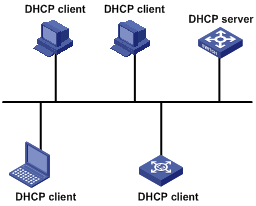
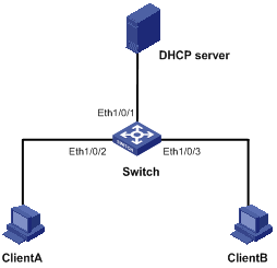
A typical DHCP application includes one DHCP server and multiple clients (such as PCs and laptops), as shown in Figure 1-1.
Figure 1-1 Typical DHCP application
DHCP IP Address Assignment
IP Address Assignment Policy
Currently, DHCP provides the following three IP address assignment policies to meet the requirements of different clients:
l Manual assignment. The administrator configures static IP-to-MAC bindings for some special clients, such as a WWW server. Then the DHCP server assigns these fixed IP addresses to the clients.
l Automatic assignment. The DHCP server assigns IP addresses to DHCP clients. The IP addresses will be occupied by the DHCP clients permanently.
l Dynamic assignment. The DHCP server assigns IP addresses to DHCP clients for predetermined period of time. In this case, a DHCP client must apply for an IP address again at the expiration of the period. This policy applies to most clients.
Obtaining IP Addresses Dynamically
A DHCP client undergoes the following four phases to dynamically obtain an IP address from a DHCP server:
1) Discover: In this phase, the DHCP client tries to find a DHCP server by broadcasting a DHCP-DISCOVER packet.
2) Offer: In this phase, the DHCP server offers an IP address. After the DHCP server receives the DHCP-DISCOVER packet from the DHCP client, it chooses an unassigned IP address from the address pool according to the priority order of IP address assignment and then sends the IP address and other configuration information together in a DHCP-OFFER packet to the DHCP client. The sending mode is decided by the flag filed in the DHCP-DISCOVER packet, refer to section "DHCP Packet Format” for details.
3) Select: In this phase, the DHCP client selects an IP address. If more than one DHCP server sends DHCP-OFFER packets to the DHCP client, the DHCP client only accepts the DHCP-OFFER packet that first arrives, and then broadcasts a DHCP-REQUEST packet containing the assigned IP address carried in the DHCP-OFFER packet.
![]()
l After the client receives the DHCP-ACK message, it will probe whether the IP address assigned by the server is in use by broadcasting a gratuitous ARP packet. If the client receives no response within specified time, the client can use this IP address. Otherwise, the client sends a DHCP-DECLINE message to the server and requests an IP address again.
l If there are multiple DHCP servers, IP addresses offered by other DHCP servers are assignable to other clients.
Updating IP Address Lease
After a DHCP server dynamically assigns an IP address to a DHCP client, the IP address keeps valid only within a specified lease time and will be reclaimed by the DHCP server when the lease expires. If the DHCP client wants to use the IP address for a longer time, it must update the IP lease.
By default, a DHCP client updates its IP address lease automatically by unicasting a DHCP-REQUEST packet to the DHCP server when half of the lease time elapses. The DHCP server responds with a DHCP-ACK packet to notify the DHCP client of a new IP lease if the server can assign the same IP address to the client. Otherwise, the DHCP server responds with a DHCP-NAK packet to notify the DHCP client that the IP address will be reclaimed when the lease time expires.
If the DHCP client fails to update its IP address lease when half of the lease time elapses, it will update its IP address lease by broadcasting a DHCP-REQUEST packet to the DHCP servers again when seven-eighths of the lease time elapses. The DHCP server performs the same operations as those described above.
DHCP Packet Format
DHCP has eight types of packets. They have the same format, but the values of some fields in the packets are different. The DHCP packet format is based on that of the BOOTP packets. The following figure describes the packet format (the number in the brackets indicates the field length, in bytes):
Figure 1-2 DHCP packet format
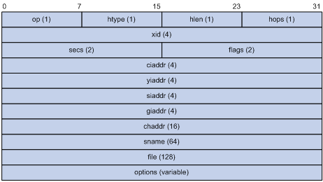
The fields are described as follows:
l op: Operation types of DHCP packets, 1 for request packets and 2 for response packets.
l htype, hlen: Hardware address type and length of the DHCP client.
l hops: Number of DHCP relay agents which a DHCP packet passes. For each DHCP relay agent that the DHCP request packet passes, the field value increases by 1.
l xid: Random number that the client selects when it initiates a request. The number is used to identify an address-requesting process.
l secs: Elapsed time after the DHCP client initiates a DHCP request.
l flags: The first bit is the broadcast response flag bit, used to identify that the DHCP response packet is a unicast (set to 0) or broadcast (set to 1). Other bits are reserved.
l ciaddr: IP address of a DHCP client.
l yiaddr: IP address that the DHCP server assigns to a client.
l siaddr: IP address of the DHCP server.
l giaddr: IP address of the first DHCP relay agent that the DHCP client passes after it sent the request packet.
l chaddr: Hardware address of the DHCP client.
l sname: Name of the DHCP server.
l file: Path and name of the boot configuration file that the DHCP server specifies for the DHCP client.
l option: Optional variable-length fields, including packet type, valid lease time, IP address of a DNS server, and IP address of the WINS server.
Protocol Specification
Protocol specifications related to DHCP include:
l RFC2131: Dynamic Host Configuration Protocol
l RFC2132: DHCP Options and BOOTP Vendor Extensions
l RFC1542: Clarifications and Extensions for the Bootstrap Protocol
l RFC3046: DHCP Relay Agent Information option
Introduction
Introduction to DHCP Snooping
For the sake of security, the IP addresses used by online DHCP clients need to be tracked for the administrator to verify the corresponding relationship between the IP addresses the DHCP clients obtained from DHCP servers and the MAC addresses of the DHCP clients.
l Layer 3 switches can track DHCP client IP addresses through DHCP relay.
l Layer 2 switches can track DHCP client IP addresses through the DHCP snooping function, which listens DHCP broadcast packets.
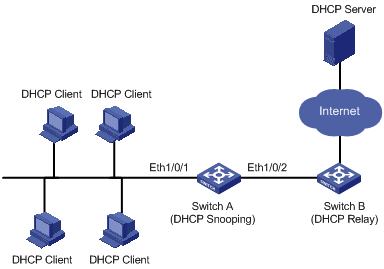
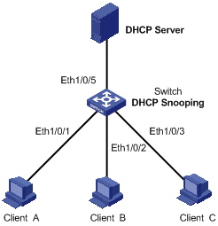
Figure 2-1 illustrates a typical network diagram for DHCP snooping application, where Switch A is an S3100 series Ethernet switch.
Figure 2-1 Typical network diagram for DHCP snooping application
On S3100-SI series Ethernet switches, DHCP snooping listens the DHCP-REQUEST packets to retrieve the IP addresses the DHCP clients obtain from DHCP servers and the MAC addresses of the DHCP clients.
On S3100-EI series Ethernet switches, DHCP snooping listens the DHCP-REQUEST packets and DHCP-ACK packets to retrieve the IP addresses the DHCP clients obtain from DHCP servers and the MAC addresses of the DHCP clients.
Introduction to DHCP Snooping Trusted/Untrusted Ports
When an unauthorized DHCP server exists in the network, a DHCP client may obtains an illegal IP address. To ensure that the DHCP clients obtain IP addresses from valid DHCP servers, The S3100-EI series Ethernet switches can specify a port to be a trusted port or an untrusted port by the DHCP snooping function.
l Trusted: A trusted port is connected to an authorized DHCP server directly or indirectly. It forwards DHCP messages to guarantee that DHCP clients can obtain valid IP addresses.
l Untrusted: An untrusted port is connected to an unauthorized DHCP server. The DHCP-ACK or DHCP-OFFER packets received from the port are discarded, preventing DHCP clients from receiving invalid IP addresses.
Introduction to Unauthorized DHCP Server Detection
S3100-SI series Ethernet switches do not support the DHCP snooping trusted port function due to limited ACL resources; however, they provide the unauthorized DHCP server detection feature to guard against network troubles caused by unauthorized DHCP servers, or prevent an attacker from assigning IP addresses to clients as a valid DHCP server.
After you enable this feature on a downstream port (which is connected to DHCP clients directly or indirectly) of a DHCP snooping enabled switch, the switch sends a DHCP-DISCOVER message. If a DHCP-OFFER message is received from the downstream port, an unauthorized DHCP server is considered present, and the switch either sends a trap, or sends a trap and administratively shuts down the port as configured.
![]()
The port that is shut down administratively is in the closed state and cannot receive or forward packets; however, using the display current-configuration command cannot display the port state. You can use the undo shutdown command in port view to enable this port.
To prevent any unauthorized DHCP server from filtering DHCP-DISCOVER messages sent by the DHCP snooping device, you can specify a source MAC address for such messages.
Overview of DHCP-Snooping Option 82
Introduction to Option 82
Option 82 is the relay agent information option in the DHCP message. It records the location information of the DHCP client.
When a DHCP relay agent (or a device enabled with DHCP snooping) receives a client’s request, it adds the Option 82 to the request message and sends it to the server.
The administrator can locate the DHCP client to further implement security control and accounting. The Option 82 supporting server can also use such information to define individual assignment policies of IP address and other parameters for the clients.
Option 82 involves at most 255 sub-options. If Option 82 is defined, at least one sub-option must be defined. Currently the DHCP relay agent supports two sub-options: sub-option 1 (circuit ID sub-option) and sub-option 2 (remote ID sub-option).
Padding content and frame format of Option 82
There is no specification for what should be padded in Option 82. Manufacturers can pad it as required. By default, the sub-options of Option 82 for S3100-EI Series Ethernet Switches (enabled with DHCP snooping) are padded as follows:
l sub-option 1 (circuit ID sub-option): Padded with the port index (smaller than the physical port number by 1) and VLAN ID of the port that received the client’s request.
l sub-option 2 (remote ID sub-option): Padded with the bridge MAC address of the DHCP snooping device that received the client’s request.
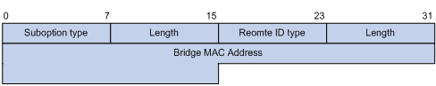
By default, when S3100-EI Series Ethernet Switches serve as DHCP snooping devices, Option 82 adopts the extended format. Refer to Figure 2-2 and Figure 2-3 for the extended format of the sub-options (with the default padding contents). That is, the circuit ID or remote ID sub-option defines the type and length of a circuit ID or remote ID.
The remote ID type field and circuit ID type field are determined by the option storage format. They are both set to “0” in the case of HEX format and to “1” in the case of ASCII format.
Figure 2-2 Extended format of the circuit ID sub-option
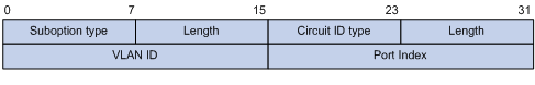
Figure 2-3 Extended format of the remote ID sub-option
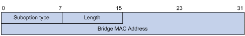
In practice, some network devices do not support the type and length identifiers of the Circuit ID and Remote ID sub-options. To interwork with these devices, S3100-EI Series Ethernet Switches support Option 82 in the standard format. Refer to Figure 2-4 and Figure 2-5 for the standard format of the sub-options (with the default padding contents). In the standard format, the Circuit ID or Remote ID sub-option does not contain the two-byte type and length fields of the circuit ID or remote ID.
Figure 2-4 Standard format of the circuit ID sub-option
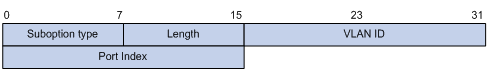
Figure 2-5 Standard format of the remote ID sub-option
Mechanism of DHCP-snooping Option 82
With DHCP snooping and DHCP-snooping Option 82 support enabled, when the DHCP snooping device receives a DHCP client’s request containing Option 82, it will handle the packet according to the handling policy and the configured contents in sub-options. For details, see Table 2-1.
Table 2-1 Ways of handling a DHCP packet with Option 82
|
Handling policy |
Sub-option configuration |
The DHCP Snooping device will… |
|
Drop |
— |
Drop the packet. |
|
Keep |
— |
Forward the packet without changing Option 82. |
|
Replace |
Neither of the two sub-options is configured |
Forward the packet after replacing the original Option 82 with the default content. The storage format of Option 82 content is the one specified with the dhcp-snooping information format command or the default HEX format if this command is not executed. |
|
Circuit ID sub-option is configured |
Forward the packet after replacing the circuit ID sub-option of the original Option 82 with the configured circuit ID sub-option in ASCII format. |
|
|
Remote ID sub-option is configured |
Forward the packet after replacing the remote ID sub-option of the original Option 82 with the configured remote ID sub-option in ASCII format. |
When receiving a DHCP client’s request without Option 82, the DHCP snooping device will add the option field with the configured sub-option and then forward the packet. For details, see Table 2-2.
Table 2-2 Ways of handling a DHCP packet without Option 82
|
Sub-option configuration |
The DHCP-Snooping device will … |
|
Neither of the two sub-options is configured. |
Forward the packet after adding Option 82 with the default contents. The format of Option 82 is the one specified with the dhcp-snooping information format command or the default HEX format if this command is not executed. |
|
Circuit ID sub-option is configured. |
Forward the packet after adding Option 82 with the configured circuit ID sub-option in ASCII format. |
|
Remote ID sub-option is configured. |
Forward the packet after adding Option 82 with the configured remote ID sub-option in ASCII format. |
![]()
The circuit ID and remote ID sub-options in Option 82, which can be configured simultaneously or separately, are independent of each other in terms of configuration sequence.
When the DHCP snooping device receives a DHCP response packet from the DHCP server, the DHCP snooping device will delete the Option 82 field, if contained, before forwarding the packet, or will directly forward the packet if the packet does not contain the Option 82 field.
Overview of IP Filtering
A denial-of-service (DoS) attack means an attempt of an attacker sending a large number of forged address requests with different source IP addresses to the server so that the network cannot work normally. The specific effects are as follows:
l The resources on the server are exhausted, so the server does not respond to other requests.
l After receiving such type of packets, a switch needs to send them to the CPU for processing. Too many request packets cause high CPU usage rate. As a result, the CPU cannot work normally.
l The switch can filter invalid IP packets through the DHCP-snooping table and IP static binding table.
DHCP-snooping table
After DHCP snooping is enabled on a switch, a DHCP-snooping table is generated. It is used to record IP addresses obtained from the DHCP server, MAC addresses, the number of the port through which a client is connected to the DHCP-snooping-enabled device, and the number of the VLAN to which the port belongs to. These records are saved as entries in the DHCP-snooping table.
IP static binding table
The DHCP-snooping table only records information about clients that obtains IP address dynamically through DHCP. If a fixed IP address is configured for a client, the IP address and MAC address of the client cannot be recorded in the DHCP-snooping table. Consequently, this client cannot pass the IP filtering of the DHCP-snooping table, thus it cannot access external networks.
To solve this problem, the switch supports the configuration of static binding table entries, that is, the binding relationship between IP address, MAC address, and the port connecting to the client, so that packets of the client can be correctly forwarded.
IP filtering
The switch can filter IP packets in the following two modes:
l Filtering the source IP address in a packet. If the source IP address and the number of the port that receives the packet are consistent with entries in the DHCP-snooping table or static binding table, the switch regards the packet as a valid packet and forwards it; otherwise, the switch drops it directly.
l Filtering the source IP address and the source MAC address in a packet. If the source IP address and source MAC address in the packet, and the number of the port that receives the packet are consistent with entries in the DHCP-snooping table or static binding table, the switch regards the packet as a valid packet and forwards it; otherwise, the switch drops it directly.
DHCP Snooping Configuration
Configuring DHCP Snooping
Table 2-3 Configure DHCP snooping
|
Operation |
Command |
Description |
|
Enter system view |
system-view |
— |
|
Enable DHCP snooping |
dhcp-snooping |
Required By default, the DHCP snooping function is disabled. |
![]()
l After DHCP snooping is enabled on an S3100 Ethernet switch, clients connected with this switch cannot obtain IP addresses dynamically through BOOTP.
l You are not recommended to configure both the DHCP snooping and selective Q-in-Q function on an S3100-EI switch, which may result in the DHCP snooping to function abnormally.
Configuring DHCP Snooping Trusted/Untrusted Ports
Table 2-4 Configure DHCP Snooping Trusted/Untrusted Ports
|
Operation |
Command |
Description |
|
Enter system view |
system-view |
— |
|
Enter Ethernet port view |
interface interface-type interface-number |
— |
|
Specify the current port as a trusted port |
dhcp-snooping trust |
Required By default, after DHCP snooping is enabled, all ports of the S3100-EI switch are untrusted ports. |
![]()
l Only the S3100-EI series among S3100 series switches support the configuration of DHCP snooping trusted ports.S3100-SI series Ethernet switches do not support the configuration of DHCP snooping trusted ports. That is, after DHCP snooping is enabled, all ports of the S3100-SI series Ethernet switches are trusted ports.
l After DHCP snooping is enabled, all ports of an S3100-EI switch are untrusted ports. You need to specify the port of the S3100-EI switch connected to the valid DHCP server as trusted to ensure that DHCP clients can obtain valid IP addresses. The trusted port and the port connected to the DHCP clients must be in the same VLAN.
Configuring Unauthorized DHCP Server Detection
![]()
Only the S3100-SI series among S3100 series switches support the unauthorized DHCP server detection.
Table 2-5 Configure unauthorized DHCP server detection
|
Operation |
Command |
Description |
|
Enter system view |
system-view |
— |
|
Enter Ethernet port view |
interface interface-type interface-number |
— |
|
Enable unauthorized DHCP server detection |
dhcp-snooping server-guard enable |
Required Disabled by default. |
|
Specify the method for handling unauthorized DHCP servers |
dhcp-snooping server-guard method { trap | shutdown } |
Optional By default, the handling method is trap. |
|
Return to system view |
quit |
— |
|
Specify a source MAC address for DHCP-DISCOVER messages sent by the snooping device |
dhcp-snooping server-guard source-mac mac-address |
Optional By default, the source MAC address of DHCP-DISCOVER messages is the bridge MAC address of the switch. |
|
Display information about unauthorized DHCP servers |
display dhcp-snooping server-guard |
Available in any view |
![]()
l You need to enable DHCP snooping before enabling unauthorized DHCP server detection.
l Do not configure unauthorized DHCP server detection on a member port of a link aggregation group.
l Currently, after specifying the source MAC address for DHCP-DISCOVER messages on an S3100-SI series switch, you cannot use the VLAN-VPN tunnel function at the same time, and vice versa. In addition, after you specify the source MAC address for DHCP-DISCOVER messages, the IGMP snooping function cannot learn router interfaces through PIM messages. For information about router interfaces, refer to Multicast Operation.
Configuring DHCP Snooping to Support Option 82
![]()
l Only the S3100-EI series among S3100 series switches support the DHCP-snooping Option 82 support feature.
l Enable DHCP snooping and specify trusted ports on the switch before configuring DHCP snooping to support Option 82.
Table 2-6 DHCP-snooping Option 82 support configuration task list
|
Task |
Remarks |
|
Required |
|
|
Optional |
|
|
Optional |
|
|
Optional |
|
|
Optional |
|
|
Optional |
Enable DHCP-snooping Option 82 support
Table 2-7 Enable DHCP-snooping Option 82 support
|
Operation |
Command |
Description |
|
Enter system view |
system-view |
— |
|
Enable DHCP-snooping Option 82 support |
dhcp-snooping information enable |
Required By default, DHCP snooping Option 82 support is disabled. |
Configure a handling policy for DHCP packets with Option 82
Table 2-8 Configure a handling policy for DHCP packets with Option 82
|
Operation |
Command |
Description |
|
Enter system view |
system-view |
Optional |
|
Configure a global handling policy for requests that contain Option 82 |
dhcp-snooping information strategy { drop | keep | replace } |
Optional The default handling policy is replace. |
|
Enter Ethernet port view |
interface interface-type interface-number |
— |
|
Configure a handling policy for requests that contain Option 82 received on the specified interface |
dhcp-snooping information strategy { drop | keep | replace } |
Optional The default policy is replace. |
![]()
If a handling policy is configured on a port, this configuration overrides the globally configured handling policy for requests received on this port, while the globally configured handling policy applies on those ports where a handling policy is not natively configured.
Configure the storage format of Option 82
S3100-EI Series Ethernet Switches support the HEX or ASCII format for the Option 82 field.
Table 2-9 Configure a storage format for the Option 82 field
|
Operation |
Command |
Description |
|
Enter system view |
system-view |
— |
|
Configure a storage format for the Option 82 field |
dhcp-snooping information format { hex | ascii } |
Optional By default, the format is hex. |
![]()
The dhcp-snooping information format command applies only to the default content of the Option 82 field. If you have configured the circuit ID or remote ID sub-option, the format of the sub-option is ASCII, instead of the one specified with the dhcp-snooping information format command.
Configure the circuit ID sub-option
Table 2-10 Configure the circuit ID sub-option
|
Operation |
Command |
Description |
|
Enter system view |
system-view |
— |
|
Enter Ethernet port view |
interface interface-type interface-number |
— |
|
Configure the circuit ID sub-option in Option 82 |
dhcp-snooping information [ vlan vlan-id ] circuit-id string string |
Optional By default, the circuit ID sub-option contains the VLAN ID and port index related to the port that receives DHCP request packets from DHCP clients |
![]()
l If you have configured a circuit ID with the vlan vlan-id argument specified, and the other one without the argument in Ethernet port view, the former circuit ID applies to the DHCP messages from the specified VLAN; while the latter one applies to DHCP messages from other VLANs.
l In a port aggregation group, you can use this command to configure the primary and member ports respectively. When Option 82 is added, however, the circuit ID sub-option is subject to the one configured on the primary port.
l The circuit ID sub-option configured on a port will not be synchronized in the case of port aggregation.
Configure the remote ID sub-option
You can configure the remote ID sub-option in system view or Ethernet port view:
l In system view, the remote ID takes effect on all interfaces. You can configure Option 82 as the system name (sysname) of the device or any customized character string in the ASCII format.
l In Ethernet port view, the remote ID takes effect only on the current interface. You can configure Option 82 as any customized character string in the ASCII format for different VLANs. That is to say, you can add different configuration rules for packets from different VLANs.
Table 2-11 Configure the remote ID sub-option in Option 82
|
Operation |
Command |
Description |
|
Enter system view |
system-view |
— |
|
Configure the remote ID sub-option in system view |
dhcp-snooping information remote-id { sysname | string string } |
Optional By default, the remote ID sub-option is the MAC address of the DHCP snooping device that received the DHCP client’s request. |
|
Enter Ethernet port view |
interface interface-type interface-number |
— |
|
Configure the remote ID sub-option in Ethernet port view |
dhcp-snooping information [ vlan vlan-id ] remote-id string string |
Optional By default, the remote ID sub-option is the MAC address of the DHCP snooping device that received the client’s request. |
![]()
l If you configure a remote ID sub-option in both system view and on a port, the remote ID sub-option configured on the port applies when the port receives a packet, and the global remote ID applies to other interfaces that have no remote ID sub-option configured.
l If you have configured a remote ID with the vlan vlan-id argument specified, and the other one without the argument in Ethernet port view, the former remote ID applies to the DHCP messages from the specified VLAN, while the latter one applies to DHCP messages from other VLANs.
l In a port aggregation group, you can use this command to configure the primary and member ports respectively. When Option 82 is added, however, the remote ID is subject to the one configured on the primary port.
l The remote ID configured on a port will not be synchronized in the case of port aggregation.
Configure the padding format for Option 82
Table 2-12 Configure the padding format for Option 82
|
Operation |
Command |
Description |
|
Enter system view |
system-view |
— |
|
Configure the padding format |
dhcp-snooping information packet-format { extended | standard } |
Optional By default, the padding format is in extended format. |
Configuring IP Filtering
![]()
Only the S3100-EI series among S3100 series switches support IP filtering.
Table 2-13 Configure IP filtering
|
Operation |
Command |
Description |
|
Enter system view |
system-view |
— |
|
Enter Ethernet port view |
interface interface-type interface-number |
— |
|
Enable IP filtering |
ip check source ip-address [ mac-address ] |
Required By default, this function is disabled. |
|
Create an IP static binding entry |
ip source static binding ip-address ip-address [ mac-address mac-address ] |
Optional By default, no static binding entry is created. |
![]()
l Enable DHCP snooping and specify trusted ports on the switch before configuring IP filtering.
l You are not recommended to configure IP filtering on the ports of an aggregation group.
l To create a static binding after IP filtering is enabled with the mac-address keyword specified on a port, the mac-address argument must be specified; otherwise, the packets sent from this IP address cannot pass the IP filtering.
l A static entry has a higher priority than the dynamic DHCP snooping entry that has the same IP address as the static one. That is, if the static entry is configured after the dynamic entry is recorded, the static entry overwrites the dynamic entry; if the static entry is configured before DHCP snooping is enabled, no DHCP client can obtain the IP address of the static entry.
l The VLAN ID of the IP static binding configured on a port is the default VLAN ID of the port.
Displaying DHCP Snooping Configuration
After the above configurations, you can verify the configurations by executing the display command in any view.
Table 2-14 Display DHCP snooping
|
Operation |
Command |
Description |
|
Display the user IP-MAC address mapping entries recorded by the DHCP snooping function |
display dhcp-snooping [ unit unit-id ] |
You can execute the display command in any view |
|
Display the (enabled/disabled) state of the DHCP snooping function and the trusted ports |
display dhcp-snooping trust |
|
|
Display the IP static binding table |
display ip source static binding [ vlan vlan-id | interface interface-type interface-number ] |
![]()
Among S3100 series ethernet switches, only S3100-EI series switches support the display dhcp-snooping trust and display ip source static binding commands.
DHCP Snooping Configuration Example
DHCP-Snooping Option 82 Support Configuration Example
Network requirements
As shown in Figure 2-6, Ethernet1/0/5 of the switch (S3100-EI) is connected to the DHCP server, and Ethernet1/0/1, Ethernet1/0/2, and Ethernet1/0/3 are respectively connected to Client A, Client B, and Client C.
l Enable DHCP snooping on the switch.
l Specify Ethernet1/0/5 on the switch as a trusted port for DHCP snooping.
l Enable DHCP-snooping Option 82 support on the switch and set the remote ID field in Option 82 to the system name of the switch. Set the circuit ID sub-option to “abcd” in DHCP packets from VLAN 1 on Ethernet 1/0/3.
Network diagram
Figure 2-6 Network diagram for DHCP-snooping Option 82 support configuration
Configuration procedure
# Enable DHCP snooping on the switch.
<Switch> system-view
[Switch] dhcp-snooping
# Specify Ethernet1/0/5 as the trusted port.
[Switch] interface Ethernet1/0/5
[Switch-Ethernet1/0/5] dhcp-snooping trust
[Switch-Ethernet1/0/5] quit
# Enable DHCP-snooping Option 82 support.
[Switch] dhcp-snooping information enable
# Set the remote ID sub-option in Option 82 to the system name (sysname) of the DHCP snooping device.
[Switch] dhcp-snooping information remote-id sysname
# Set the circuit ID sub-option in DHCP packets from VLAN 1 to “abcd” on Ethernet 1/0/3.
[Switch] interface Ethernet1/0/3
[Switch-Ethernet1/0/3] dhcp-snooping information vlan 1 circuit-id string abcd
Unauthorized DHCP Server Detection Configuration Example
Network requirements
As shown in Figure 2-7, Ethernet 1/0/1 of the switch (S3100-SI) is connected to the DHCP server, and Ethernet 1/0/2 and Ethernet 1/0/3 are respectively connected to Client A, Client B.
l Enable DHCP snooping on the switch.
l Enable unauthorized DHCP server detection on Ethernet 1/0/2 and Ethernet 1/0/3. When an authorized DHCP server is detected on Ethernet 1/0/2, a trap message will be sent; when an authorized DHCP server is detected on Ethernet 1/0/3, the interface is shut down administratively.
l To prevent attackers from filtering the detecting DHCP-DISCOVER packets, specify the source MAC address for such packets as 000f-e200-1111 (different from the bridge MAC address of the switch) on the switch.
Network diagram
Figure 2-7 Network diagram for unauthorized DHCP server detection
Configuration procedure
# Enable DHCP snooping.
<Sysname> system-view
Enter system view, return to user view with Ctrl+Z.
[Sysname] dhcp-snooping
# Specify the source MAC address for the DHCP-DISCOVER messages as 000f-e200-1111.
[Sysname] dhcp-snooping server-guard source-mac 000f-e200-1111
# Enable unauthorized DHCP server detection on Ethernet 1/0/2.
[Sysname] interface ethernet1/0/2
[Sysname-Ethernet1/0/2] dhcp-snooping server-guard enable
# Specify the method for handling unauthorized DHCP servers as trap on Ethernet 1/0/2.
[Sysname-Ethernet1/0/2] dhcp-snooping server-guard method trap
[Sysname-Ethernet1/0/2] quit
# Enable unauthorized DHCP server detection on Ethernet 1/0/3.
[Sysname] interface ethernet1/0/3
[Sysname-Ethernet1/0/3] dhcp-snooping server-guard enable
# Specify the method for handling unauthorized DHCP servers as shutdown on Ethernet 1/0/3..
[Sysname-Ethernet1/0/3] dhcp-snooping server-guard method shutdown
IP Filtering Configuration Example
Network requirements
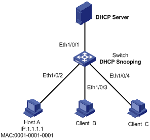
As shown in Figure 2-8, Ethernet1/0/1 of the S3100-EI switch is connected to DHCP server and Ethernet1/0/2 is connected to Host A. The IP address and MAC address of Host A are 1.1.1.1 and 0001-0001-0001 respectively. Ethernet1/0/3 and Ethernet1/0/4 is connected to DHCP Client B and Client C.
l Enable DHCP snooping on the switch, and specify Ethernet1/0/1 as the DHCP snooping trusted port.
l Enable IP filtering on Ethernet1/0/2, Ethernet1/0/3, and Ethernet1/0/4 to prevent attacks to the server from clients using fake source IP addresses.
l Create static binding entries on the switch, so that Host A using a fixed IP address can access the external network.
Network diagram
Figure 2-8 Network diagram for IP filtering configuration
Configuration procedure
# Enable DHCP snooping on the switch.
<Switch> system-view
[Switch] dhcp-snooping
# Specify Ethernet1/0/1 as the trusted port.
[Switch] interface Ethernet1/0/1
[Switch-Ethernet1/0/1] dhcp-snooping trust
[Switch-Ethernet1/0/1] quit
# Enable IP filtering on Ethernet1/0/2, Ethernet1/0/3, and Ethernet1/0/4 to filter packets based on the source IP addresses/MAC addresses.
[Switch] interface Ethernet1/0/2
[Switch-Ethernet1/0/2] ip check source ip-address mac-address
[Switch-Ethernet1/0/2] quit
[Switch] interface Ethernet1/0/3
[Switch-Ethernet1/0/3] ip check source ip-address mac-address
[Switch-Ethernet1/0/3] quit
[Switch] interface Ethernet1/0/4
[Switch-Ethernet1/0/4] ip check source ip-address mac-address
[Switch-Ethernet1/0/4] quit
# Create static binding entries on Ethernet1/0/2 of the switch.
[Switch] interface Ethernet1/0/2
[Switch-Ethernet1/0/2] ip source static binding ip-address 1.1.1.1 mac-address 0001-0001-0001
![]()
The contents of this chapter are only applicable to the S3100-EI series among S3100 series switches.
Introduction to DHCP Packet Rate Limit
To prevent ARP attacks and attacks from unauthorized DHCP servers, ARP packets and DHCP packets will be processed by the switch CPU for validity checking. But, if attackers generate a large number of ARP packets or DHCP packets, the switch CPU will be under extremely heavy load. As a result, the switch cannot work normally and even goes down.
S3100-EI series Ethernet switches support ARP and DHCP packet rate limit on a port and shut down the port under attack to prevent hazardous impact on the device CPU. For details about ARP packet rate limit, refer to ARP Operation in this manual. The following describes only the DHCP packet rate limit function.
After DHCP packet rate limit is enabled on an Ethernet port, the switch counts the number of DHCP packets received on this port per second. If the number of DHCP packets received per second exceeds the specified value, packets are passing the port at an over-high rate, which implies an attack to the port. In this case, the switch shuts down this port so that it cannot receive any packet, thus protect the switch from attacks.
In addition, the switch supports port state auto-recovery. After a port is shut down due to over-high packet rate, it resumes automatically after a configurable period of time.
![]()
When both port state auto-recovery interval for over-high ARP packet rate and port state auto-recovery interval for over-high DHCP packet rate are configured on a port, the shorter one will be the auto-recovery time.
Configuring DHCP Packet Rate Limit
Configuring DHCP Packet Rate Limit
Table 3-1 Configure rate limit of DHCP packets
|
Operation |
Command |
Description |
|
Enter system view |
system-view |
— |
|
Enter port view |
interface interface-type interface-number |
— |
|
Enable the DHCP packet rate limit function |
dhcp rate-limit enable |
Required By default, DHCP packet rate limit is disabled. |
|
Configure the maximum DHCP packet rate allowed on the port |
dhcp rate-limit rate |
Optional By default, the maximum rate is 15 pps. |
|
Enable the port state auto-recovery function |
dhcp protective-down recover enable |
Optional By default, the port state auto-recovery function is disabled. |
|
Set the port state auto-recovery interval |
dhcp protective-down recover interval interval |
Optional The port state auto-recovery interval is 300 seconds. |
![]()
l Enable the port state auto-recovery function before setting the auto-recovery interval.
l You are not recommended to configure DHCP packet rate limit on the ports of an aggregation group.
Configuring Port State Auto Recovery
Table 3-2 Configure port state auto recovery
|
Operation |
Command |
Description |
|
Enter system view |
system-view |
— |
|
Enable port state auto-recovery |
dhcp protective-down recover enable |
Required By default, this function is disabled. |
|
Configure the port state auto-recovery interval |
dhcp protective-down recover interval interval |
Optional By default, the auto-discovery interval is 300 seconds. |
Rate Limit Configuration Example
Network requirements
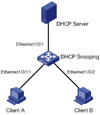
As shown in Figure 3-1, Ethernet1/0/1 of the S3100-EI switch is connected to the DHCP server. Ethernet1/0/2 is connected to client B and Ethernet1/0/11 is connected to client A.
l Enable DHCP snooping on the switch, and specify Ethernet1/0/1 as the DHCP snooping trusted port.
l Configure DHCP packet rate limit on Ethernet1/0/11 and set the maximum DHCP packet rate allowed on the port to 100 pps.
l Set the port state auto-recovery interval to 30 seconds on the switch.
Networking diagram
Figure 3-1 Network diagram for DHCP packet rate limit configuration
Configuration procedure
# Enable DHCP snooping on the switch.
<Switch> system-view
[Switch] dhcp-snooping
# Specify Ethernet1/0/1 as the trusted port.
[Switch] interface Ethernet1/0/1
[Switch-Ethernet1/0/1] dhcp-snooping trust
[Switch-Ethernet1/0/1] quit
# Enable auto recovery.
[Switch] dhcp protective-down recover enable
# Set the port state auto-recovery interval to 30 seconds.
[Switch] dhcp protective-down recover interval 30
# Enter port view.
[Switch] interface Ethernet 1/0/11
# Enable DHCP packet rate limit on Ethernet1/0/11.
[Switch-Ethernet1/0/11] dhcp rate-limit enable
# Set the maximum DHCP packet rate allowed on Ethernet1/0/11 to 100 pps.
[Switch-Ethernet1/0/11] dhcp rate-limit 100
Introduction to DHCP Client
After you specify a VLAN interface as a DHCP client, the device can use DHCP to obtain parameters such as IP address dynamically from the DHCP server, which facilitates user configuration and management.
Refer to “Obtaining IP Addresses Dynamically” for the process of how a DHCP client dynamically obtains an IP address through DHCP.
Introduction to BOOTP Client
After you specify an interface as a bootstrap protocol (BOOTP) client, the interface can use BOOTP to get information (such as IP address) from the BOOTP server, which simplifies your configuration.
Before using BOOTP, an administrator needs to configure a BOOTP parameter file for each BOOTP client on the BOOTP server. The parameter file contains information such as MAC address and IP address of a BOOTP client. When a BOOTP client sends a request to the BOOTP server, the BOOTP server will search for the BOOTP parameter file and return it to the client.
A BOOTP client dynamically obtains an IP address from a BOOTP server in the following way:
1) The BOOTP client broadcasts a BOOTP request, which contains its own MAC address.
2) The BOOTP server receives the request and searches for the corresponding IP address according to the MAC address of the BOOTP client and sends the information in a BOOTP response to the BOOTP client.
3) The BOOTP client obtains the IP address from the received response.
![]()
Because a DHCP server can interact with a BOOTP client, you can use the DHCP server to assign an IP address to the BOOTP client, without needing to configure any BOOTP server.
Configuring a DHCP/BOOTP Client
Table 4-1 Configure a DHCP/BOOTP client
|
Operation |
Command |
Description |
|
Enter system view |
system-view |
— |
|
Enter VLAN interface view |
interface Vlan-interface vlan-id |
— |
|
Configure the VLAN interface to obtain IP address through DHCP or BOOTP |
ip address { bootp-alloc | dhcp-alloc } |
Required By default, no IP address is configured for the VLAN interface. |
![]()
l Currently, an S3100 Ethernet switch functioning as the DHCP client can use an IP address for 24 days at most. That is, the DHCP client can obtain an address lease for no more than 24 days even though the DHCP server offers a longer lease period.
l An S3100 Ethernet switch functioning as a DHCP client supports default route creation. That is, the DHCP client creates a default route with the next hop being the gateway assigned by the DHCP server. To view detailed information about the default route, run the display ip routing-table command on the switch.
![]()
To improve security and avoid malicious attack to the unused SOCKETs, S3100 Ethernet switches provide the following functions:
l UDP 67 and UDP 68 ports used by DHCP are enabled only when DHCP is enabled.
l UDP 67 and UDP 68 ports are disabled when DHCP is disabled.
The specific implementation is:
l Using the ip address dhcp-alloc command enables the DHCP client, and UDP port 68.
l Using the undo ip address dhcp-alloc command disables the DHCP client, and UDP port 68.
DHCP Client Configuration Example
Network requirements
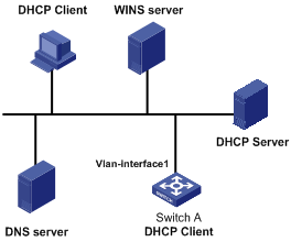
Using DHCP, VLAN-interface 1 of Switch A is connected to the LAN to obtain an IP address from the DHCP server.
Network diagram
Configuration procedure
The following describes only the configuration on Switch A serving as a DHCP client.
# Configure VLAN-interface 1 to dynamically obtain an IP address by using DHCP.
<SwitchA> system-view
[SwitchA] interface Vlan-interface 1
[SwitchA-Vlan-interface1] ip address dhcp-alloc
Displaying DHCP/BOOTP Client Configuration
Table 4-2 Displaying DHCP/BOOTP Client
|
Operation |
Command |
Description |
|
Display related information on a DHCP client |
display dhcp client [ verbose ] |
Optional Available in any view |
|
Display related information on a BOOTP client |
display bootp client [ interface Vlan-interface vlan-id ] |