- Table of Contents
- Related Documents
-
| Title | Size | Download |
|---|---|---|
| 01-Text | 1.09 MB |
Requirements on Temperature/Humidity
Requirements on Electromagnetic Susceptibility
Installing a AC onto a 19-Inch Rack
Installing a AC on a Workbench
Power Cords and Ground Wire Connection
Gigabit Ethernet Interface Connection
Connecting an Ethernet Electrical Interface
Connecting an Ethernet Optical Interface
Setting up the Configuration Environment
AC Software Maintenance Methods
Upgrading BootWare Through a Serial Interface
Modifying Serial Interface Parameters
Upgrading an Application Program Through a Serial Interface
Upgrading an Application Program Through an Ethernet Interface
Configuring Ethernet Interface Parameters
Upgrading an Application Program
Maintaining Application Programs and Configurations Through Command Lines
Maintaining the AC Through the TFTP Server
Maintaining the AC Through the FTP Server
Maintaining Application and Configuration Files in BootWare
Backing Up and Restoring BootWare
6 Maintenance and Troubleshooting
The models listed in this manual are not applicable to all regions. Please consult the local agents for the models applicable to your region.
WX5002 Access Controller
H3C WX5002 Access Controller (AC), which are wholly developed by Hangzhou H3C Technologies Co., Ltd. (hereinafter referred to as H3C). An AC, together with Fit APs (H3C WA2110-AG wireless access points, H3C WA2200 Series wireless access points and H3C WA2600 Series wireless access points developed by H3C), is used to deploy a wireless LAN (WLAN).
A WX5002 supports up to 64 APs and 2,000 wireless users.
Appearance
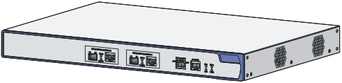
A WX5002 AC provides two gigabit Ethernet electrical interfaces, two gigabit Ethernet optical interfaces (combo interfaces), one 10/100 BASE-TX out-of-band management interface, and one console interface on its front panel, and two AC power sockets on its rear panel. Figure 1-1 shows the appearance of a WX5002 AC.
Figure 1-1 Appearance of a WX5002 AC
Front Panel
Figure 1-2 Front panel of a WX5002 AC

|
(1) Gigabit Ethernet interface 2—SFP optical interface |
|
|
(2) 1000 Mbps LED of gigabit Ethernet interface 2 |
|
|
(3) 10/100 Mbps LED of gigabit Ethernet interface 2 |
|
|
(4) 10/100/1000 Base-T auto-sensing Ethernet electrical interface 2 |
|
|
(5) Gigabit Ethernet interface 1—SFP optical interface |
|
|
(6) 1000 Mbps LED of gigabit Ethernet interface 1 |
|
|
(7) 10/100 Mbps LED of gigabit Ethernet interface 1 |
|
|
(8) 10/100/1000 Base-T auto-sensing Ethernet electrical interface 1 |
|
|
(9) Active LED of 10/100 Base-TX out-of-band management interface |
|
|
(10) 10/100 Base-TX out-of-band management interface |
|
|
(11) Link LED of 10/100 Base-TX out-of-band management interface |
|
|
(12) Console interface |
(13) System LED |
|
(14) Alarm LED of the system |
(15) LED of power supply 1 |
|
(16) LED of power supply 2 |
|
Rear Panel
Figure 1-3 Rear panel of a WX5002 AC
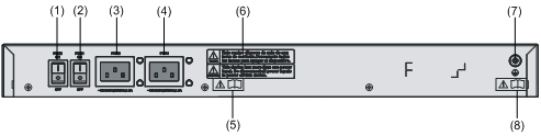
|
(1) Switch of AC power socket 2 |
(2) Switch of AC power socket 1 |
|
(3) AC power socket 2 |
(4) AC power socket 1 |
|
(5) OPEN BOOK sign |
(6) CAUTION sign |
|
(7) Grounding terminal |
(8) OPEN BOOK sign |
OPEN BOOK and CAUTION signs: Refer to related sections when performing the following operations:
Table 1-1 OPEN BOOK sign description
|
Operation |
Related section |
|
Connect the power cord |
|
|
Ground the device |
Power Supply System
A WX5002 AC uses AC power supply, and provides two AC power sockets. The two AC power sockets can separately provide power supply for the WX5002 AC, or provide 1+1 redundancy backup for the AC to enhance the system reliability.
AC input:
Rated voltage range: 100 VAC to 240 VAC; 50 Hz or 60 Hz
Input voltage range: 90 VAC to 264 VAC; 47 Hz to 63 Hz
Cooling System
A WX5002 AC provides two fans for heat dissipation.
LEDs
For the convenience of monitoring the running status, WX5002 AC provide LEDs on the front panel, as shown in Figure 1-2. For details about the LEDs, see Table 1-2.
|
LED |
Mark |
Status |
Description |
|
LED of AC power socket 1 |
PWR1 |
Solid green |
AC power socket 1 provides power normally. |
|
OFF |
AC power socket 1 does not provide power or the power supply is abnormal. |
||
|
LED of AC power socket 2 |
PWR2 |
Solid green |
AC power socket 2 provides power normally. |
|
OFF |
AC power socket 2 does not provide power or the power supply is abnormal. |
||
|
System LED |
SYS |
Flashing green (1 Hz) |
The CPU runs normally. |
|
ON or OFF |
The CPU runs abnormally. |
||
|
Alarm LED |
ALM |
OFF |
The system runs normally. |
|
Flashing red (1 Hz) |
The system runs abnormally. |
||
|
10/100 BASE-TX interface LED |
ACT |
Flashing yellow (6 Hz) |
The interface is receiving or transmitting data. |
|
OFF |
No data is being received or sent on the interface |
||
|
LINK |
Solid green |
Interface connection succeeds. |
|
|
OFF |
The interface is not connected or the connection fails. |
||
|
LED of gigabit combo interface 1 |
1000M |
Solid green |
1000 Mbps interface connection succeeds. |
|
Flashing green (6 Hz) |
The 1000 Mbps interface is receiving or transmitting data. |
||
|
OFF |
The 1000 Mbps interface is not connected or the connection fails. |
||
|
10/100M |
Solid yellow |
10/100 Mbps interface connection succeeds. |
|
|
Flashing yellow (6 Hz) |
The 10/100 Mbps interface is receiving or transmitting data. |
||
|
OFF |
The 10/100 Mbps interface is not connected or the connection fails. |
||
|
LED of gigabit combo interface 2 |
1000M |
Solid green |
1000 Mbps interface connection succeeds. |
|
Flashing green (6 Hz) |
The 1000 Mbps interface is receiving or transmitting data. |
||
|
OFF |
The 1000 Mbps interface is not connected or the connection fails. |
||
|
10/100M |
Solid yellow |
10/100 Mbps interface connection succeeds. |
|
|
Flashing yellow (6 Hz) |
The 10/100 Mbps interface is receiving or transmitting data. |
||
|
OFF |
The 10/100 Mbps interface is not connected or the connection fails. |
System Specifications
Table 1-3 System specifications of the WX5002 AC
|
Item |
Data |
|
|
Dimensions (H × W × D) |
43.6 × 440 × 300 mm (1.7 × 17.3 × 11.8 in.) |
|
|
Weight |
4.1 kg (9.0 lb.) |
|
|
Management interface |
One console interface, one 10/100 BASE-TX out-of-band management interface |
|
|
GE interfaces on the front panel |
Two 10/100/1000 BASE-T auto-sensing Ethernet electrical interfaces Two gigabit SFP Ethernet optical interfaces |
|
|
Optional SFP modules |
1000 BASE-SX SFP optical module 1000 BASE-LX SFP optical module |
|
|
Processor |
BCM1250 700 M |
|
|
DRAM configuration |
DDRI 512 MB |
|
|
Flash configuration |
32 MB |
|
|
Input voltage |
AC |
Rated voltage range: 100 VAC to 240 VAC, 50 Hz or 60 Hz Input voltage range: 90 VAC to 264 VAC, 47 Hz to 63 Hz |
|
Max power consumption (full load) |
50 W |
|
|
Operating temperature |
0°C to 45°C (32°F to 113°F) |
|
|
Relative humidity (noncondensing) |
10% to 90% |
|
![]()
Either a gigabit SFP Ethernet optical interface or its corresponding 10/100/1000 BASE-T auto-sensing Ethernet electrical interface can be used at a time.
SFP Modules
A WX5002 AC provides two gigabit SFP Ethernet optical interfaces. You can choose the following SFP modules:
l 1000 BASE-SX SFP module
l 1000 BASE-LX SFP module
The following table describes the Ethernet optical interface attributes.
Table 1-4 Ethernet optical interface attributes
|
Attribute |
Description |
|||||
|
Multimode short-haul (850 nm) |
Single-mode medium-haul (1310 nm) |
Single-mode long-haul (1310 nm) |
Single-mode long-haul (1550 nm) |
Single-mode ultra-long haul (1550 nm) |
||
|
Connector |
SFP/LC |
|||||
|
Optical fiber |
62.5 μm/125 μm multimode |
9 μm /125 μm single-mode |
9 μm /125 μm single-mode |
9 μm /125 μm single-mode |
9 μm /125 μm single-mode |
|
|
Max. transmission distance |
0.55 km (0.34 mi) |
10 km (6.21 mi) |
40 km (24.86 mi) |
40 km (24.86 mi) |
70 km (43.50 mi) |
|
|
Central wavelength |
850 nm |
1310 nm |
1310 nm |
1550 nm |
1550 nm |
|
|
Optical transmit power |
Min. |
-9.5 dBm |
-9 dBm |
-2 dBm |
-4 dBm |
-4 dBm |
|
Max. |
0 dBm |
-3 dBm |
5 dBm |
1 dBm |
2 dBm |
|
|
Receiving sensitivity |
-17 dBm |
-20 dBm |
-23 dBm |
-21 dBm |
-22 dBm |
|
|
Operating mode |
1000 Mbps Full duplex |
|||||
Safety Precautions
To avoid any device impairment and bodily injury caused by improper use, observe these rules:
l Pull the power plug(s) out of the AC before cleaning the AC. Do not clean the AC using wet cloth or liquid.
l Keep the AC away from water or dampness. Prevent water or moisture from entering the AC chassis.
l Do not place the AC on an unstable case or desk. The switch might be damaged severely in case of a fall.
l Ensure proper ventilation in the equipment room and keep the vents of the AC free of obstruction.
l Make sure that the operating voltage is within the range labeled on the AC.
l Do not open the chassis when the AC is operating or when electrical hazards are present to avoid electrical shocks.
l When replacing interface cards, wear ESD-preventive gloves to avoid damaging the cards.
Installation Site Checking
The WX5002 AC must be used indoors. You can mount a AC in a cabinet or on a workbench, but make sure that:
l Adequate clearances are reserved at the air inlet/exhaust vents for heat dissipation.
l The cabinet or workbench has a good ventilation system.
l The cabinet is sturdy enough to support the AC and its accessories.
l The cabinet or workbench is well earthed.
To ensure normal operation and a long service life of your AC, install it in an environment that meets the requirements described in the following subsections.
Requirements on Temperature/Humidity
You must maintain a proper temperature and humidity in the equipment room. A long term of high humidity may lead to bad insulation, electricity leakage, mechanical property changes, and corrosion. However, if the relative humidity is too low, captive screws may become loose as a result of contraction of insulation washers and static electricity may be produced in a dry environment to jeopardize the circuits on the device. A high temperature is the most undesirable condition, because it accelerates the aging of insulation materials and thus significantly lowers the reliability and service life of the AC.
Requirements on Cleanness
Dust is a hazard to the operating safety of the AC. The dust accumulated on the chassis can be adsorbed by static electricity and result in poor contact of metal connectors or metal contact points. Especially, when the relative indoor humidity is low, electrostatic adsorption is more likely to happen. This can not only shorten the service life of the AC but also cause communications failures. The following table lists the dust concentration limit.
Table 2-1 Dust concentration limit in the equipment room
|
Physical active substance |
Concentration limit (particles/m3) |
|
Dust |
≤ 3 × 10⁴ (No visible dust on the tabletop over three days) |
|
Note: The dust particle diameter is ≥ 5 μm |
|
Besides the dust requirements, the AC equipment room also needs to strictly meet the requirements on the concentration of salt, acid, and sulfide. These harmful gases can accelerate the metallic corrosion and the aging process of some parts. The specific limits of the harmful gases such as SO2, H2S, NO2, NH3 and CI2 are given in the following table.
Table 2-2 Limit on harmful gases in the equipment room
|
Gas |
Maximum concentration (mg/m3) |
|
SO2 |
0.2 |
|
H2S |
0.006 |
|
NH3 |
0.05 |
|
Cl2 |
0.01 |
Requirements on Electromagnetic Susceptibility
The operation of your AC may be affected by external interferences, such as capacitance coupling, inductance coupling, electromagnetic wave radiation, common impedance (including the grounding system) coupling, and the conducted interference of leads (power cords, signaling cables and output wires). To eliminate the interferences,
l For the AC power supply that adopts the TN system, use a single-phase three-wire power socket with a protection earth (PE) to effectively filter interference from the power grid.
l Keep the AC away from high-power radio transmitters, radars, and high-frequency heavy-current devices.
l Use electromagnetic shielding measures when necessary. For example, use shielded interface cables.
l Route interface cables only indoors to prevent signal interfaces from getting damaged by over-voltage or over-current caused by lightning strikes.
Laser Safety
WX5002 AC are Class 1 laser devices.
![]()
When the optional optical interfaces on a WX5002 AC are operating, avoid staring into the optical interfaces because the high-energy laser beam emitted from the optical fiber may hurt your retina.
Installation Tools
l Flathead screwdriver
l Phillips screwdriver
l ESD-preventive wrist strap
![]()
![]()
When you ask your sales agent to maintain your AC, you must ensure that the dismantlement-preventive seal on a mounting screw of the AC chassis is intact. If you want to open the chassis, you should contact the agent for permission. Otherwise, you will bear any consequence resulting from your actions.
Installation Procedure
Installing a AC onto a 19-Inch Rack
Follow these steps to mount the AC onto a standard 19-inch rack:
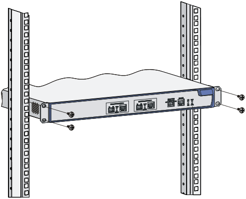
Step 1: Check that the rack is sturdy and properly earthed. Attach a mounting ear to both sides of the AC front panel with screws.
Step 2: Place the AC on a tray and slide it to a proper position along the guide rails, reserving a suitable clearance between the AC and the guide rails.
Step 3: Fix the mounting ears to the square-holed brackets with screws and make sure that the AC is fixed horizontally and securely.
Figure 3-1 Install a AC onto a 19-inch rack

Installing a front mounting ear
The following figures illustrate the installation of a front mounting ear:
Figure 3-2 Install a front mounting ear onto a AC
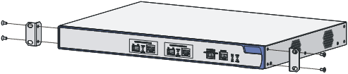
Figure 3-3 Install a front mounting ear onto a square-holed bracket
Installing a AC on a Workbench
In many cases, standard 19-inch racks are not available to users and ACs are often installed on clean workbenches. When installing an AC on a workbench,
l Make sure that the workbench is flat, sturdy and well earthed.
l Keep the environment well ventilated and reserve a clearance of 10 cm (3.9 in.) around the chassis for heat dissipation.
l Place no heavy objects on the AC.
l Keep at least a vertical distance of 1.5 cm (0.59 in.) between ACs in the case of stack application.
Power Cords and Ground Wire Connection
Connecting the AC Power Cord
AC power socket (recommended)
You are recommended to use a single-phase three-wire power socket with a neural point or a multifunction PC socket. The neutral point of the power in the building must be well grounded. Usually, the neutral points of power supplies in buildings are already grounded during cabling. Still, you need to check that the power supply of the building is reliably grounded.
Connecting the AC power cord
Step 1: Connect one end of the ground wire (delivered with the AC) to the grounding terminal on the rear panel of the chassis and the other end to the near ground.
Step 2: Connect one end of the power cord to either power socket on the rear panel of the chassis, and the other end to the power supply.
Step 3: Install the power cord retainer for the AC power cord. Insert the two ends of the power cord retainer into the slots on both sides of the AC power socket, and then set the power cord into the notch of the power cord retainer.
Figure 3-4 Install the AC power cord retainer
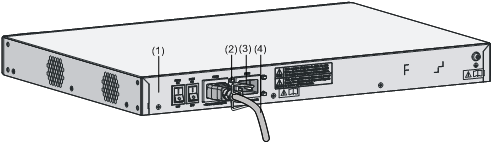
|
(1) Rear panel of the AC |
(2) Power cord retainer slots |
|
(3) AC power cord retainer |
(4) AC power cord |
![]()
l The AC power cord retainer can prevent the AC power cord from falling off.
l Whether a power cord retainer is needed depends on the power supply system of the country.
Step 4: Check whether the corresponding PWR LED on the front panel of the AC is ON. If the LED is ON, the power cord is properly connected.
![]()
Connecting the Ground Wire
![]()
Connect the AC ground wire properly since it is crucial to lightning protection and electromagnetic susceptibility (EMS).
l When a grounding strip is available, attach one end of the yellow-green ground wire of the AC to the grounding terminal on the grounding strip and fasten the captive nut. Note that the fire main and lightning rod of a building are not suitable for grounding the AC. The ground wire of the AC should be connected to the grounding device in the equipment room.
Figure 3-5 Ground the AC through a grounding strip
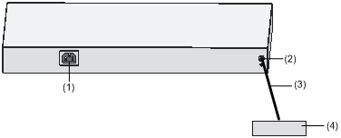
|
(1) AC power socket |
(2) Grounding terminal |
|
(3) Protection ground wire |
(4) Grounding strip |
l When there is no grounding strip but earth is available nearby and allows a grounding body to be buried, hammer an angle steel or steel pipe longer than 0.5 m (1.64 ft) into the earth. In this case, weld the yellow-green ground wire of the AC onto the angle steel or steel pipe, and treat the joint for corrosion protection.
Figure 3-6 Ground the AC by burying a grounding body into the earth
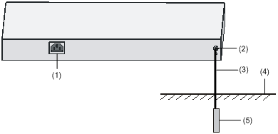
|
(1) AC power socket |
(2) Grounding terminal |
(3) Protection ground wire |
|
(4) Earth |
(5) Angle steel |
|
l For an AC-powered AC, if neither of the above-mentioned two conditions is available, ground the AC through a PE wire of the AC power supply. In this case, make sure the PE wire is well connected to the ground in the power distribution room or on the AC transformer side.
Figure 3-7 Ground the AC through an AC PE wire

|
(1) AC power socket |
(2) Grounding terminal |
(3) Power transformer |
|
(4) PE wire |
(5) Three-core AC power cord |
|
Console Cable Connection
Console Cable
A console cable is an 8-core cable. One end of the cable is a crimped RJ-45 connector and is connected to the console interface of the AC. The other end is a DB-9 female connector and is connected to the 9-pin serial interface on the console terminal. Figure 3-8 shows a console cable.
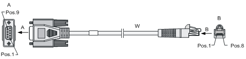
Table 3-1 Console cable pins and mapping relation
|
RJ-45 |
Signal |
Direction |
DB9 (MODEM) |
DB9 (CONSOLE) |
|
1 |
RTS |
→ |
7 |
8 |
|
2 |
DTR |
→ |
4 |
6 |
|
3 |
TXD |
→ |
3 |
2 |
|
4 |
DCD |
← |
1 |
5 |
|
5 |
GND |
— |
5 |
5 |
|
6 |
RXD |
← |
2 |
3 |
|
7 |
DSR |
← |
6 |
4 |
|
8 |
CTS |
← |
8 |
7 |
Connecting the Console Cable
Follow these steps to connect a terminal device, a PC for example, to the AC:
Step 1: Plug the DB-9 female connector of the console cable to the serial interface of the PC or terminal where the AC is to be configured.
Step 2: Connect the RJ-45 connector of the console cable to the console interface of the AC.
![]()
![]()
For a powered-on AC:
l When connecting a PC to the AC, you are recommended to first connect the DB-9 connector of the console cable to the PC, and then the RJ-45 connector to the console interface of the AC.
l When disconnecting a PC from the AC, you are recommended to first disconnect the RJ-45 connector, and then the DB-9 connector.
Gigabit Ethernet Interface Connection
A WX5002 AC provides two gigabit Ethernet combo interfaces on its front panel. The connection methods of the gigabit Ethernet electrical interface and the gigabit Ethernet optical interface are respectively described here.
Connecting an Ethernet Electrical Interface
Cables for connecting an Ethernet electrical interface
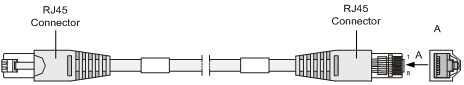
Ethernet electrical interfaces usually use category 5 twisted pair cables, as shown in Figure 3-9.
Ethernet cables fall into the following categories:
l Standard cable, also called straight-through cable. At both ends of the cable, wires are crimped in the RJ-45 connectors in the same sequence. Such a cable is used to connect a terminal device (PC and AC for example) to a hub or LAN Switch.
l Crossover cable. Wires are crimped in the RJ-45 connectors in different sequences at the two ends of the cable. Such a cable is used to connect a terminal device (PC and AC for example) to a terminal device. You can make crossover cables yourself as needed.
![]()
In making network cables, shielded cables are preferred for electromagnetic compatibility sake.
Electrical interface connection procedure
![]()
If you connect a twisted-pair cable to a 10/100/1000 Mbps Ethernet electrical interface and an optical fiber to a 10/100/1000 Mbps Ethernet optical interface as well, the system considers the electrical interface as the working interface by default.
Step 1: Connect one end of the Ethernet cable to an Ethernet electrical interface and the other end to the peer device.
l A 10/100/1000 Mbps Ethernet interface supports MDI/MDIX auto-sensing. Therefore you can use a crossover cable or a straight-through cable to connect the interface to a hub or LAN Switch.
Step 2: View the LED of the Ethernet interface. ON means a link is present. OFF means no link is present. If the LED is OFF, check the line for the cause.
Connecting an Ethernet Optical Interface
Cables for connecting an Ethernet optical interface
For 10/100/1000 Mbps Ethernet optical interfaces, use single-mode or multi-mode optical fibers to connect to the Ethernet based on the type of the installed 1000 Base-SX/LX SFP modules. As the optical interfaces of these SFP modules use LC-type fiber-optic connectors, you must use fibers with LC-type connectors for them. All these SFP modules are hot swappable.
Optical interface connection procedure
![]()
When connecting optical fibers, make sure that:
l The curvature radius of fibers is no less than 10 cm (3.9 in.).
l The Tx and Rx connectors are correctly connected.
l The fiber ends are clean.
![]()
Laser is dangerous! To protect your eyes against radiation harm, never stare into an optical fiber connector directly.
Step 1: Put on an ESD-preventive wrist strap and make sure that the ESD-preventive wrist strap is properly grounded. Then take the SFP module out of the package.
Step 2: Remove the optical module filler plug from the shielding hood of the optical interfaces of the AC.
Step 3: Hold the SFP module and slide the SFP module along the optical interface shielding hood gently until the SFP module makes skin contact with the AC.
Step 4: Distinguish between the Rx and Tx interfaces. Connect one end of an optical fiber to the Rx interface of the AC and the other end to the Tx interface of the peer device. Use another fiber to connect the AC and the peer device in the opposite way.
Step 5: Power on the AC and check the 1000 Mbps LED of the 10M/100M/1000M Ethernet interface. ON means the Rx link is present. OFF means no Rx link is present. If the LED is OFF, check the line for the cause.
Installation Verification
After installation, make sure that:
l The correct power supply is used.
l The ground wire is securely connected.
l Both the console cable and power cord are correctly connected.
l All interface cables are routed indoors. If there are cables outdoors, check that a AC power strip with lightning protection and lightning arresters for network interfaces have been correctly connected.
Setting up the Configuration Environment
Set up the configuration environment as shown below:
l Connect a terminal (a PC in this example) to the console interface on the AC with a console cable.
Figure 4-1 Network diagram for initial startup

Connecting the Console Cable
Connect a console cable as follow:
Step 1: Connect the DB-9 female connector of the console cable to the serial interface of the PC where the AC is to be configured.
Step 2: Connect the RJ-45 connector of the console cable to the console interface of the AC.
Setting Terminal Parameters
Step 1: Start the PC and run the terminal emulation program such as the Terminal of Windows 3.1 or the HyperTerminal of Windows 95/98/NT/2000/XP.
Step 2: Set terminal parameters (take the HyperTerminal of Windows XP as an example).
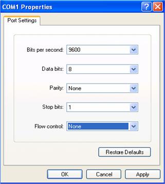
Parameter requirements: Set the bits per second to 9600, data bits to 8, parity to none, stop bits to 1, and flow control to none. Select VT100 as terminal emulation. The specific procedure is as follows:
1)
Select Start > Program > Accessories
> Communications > HyperTerminal to enter the HyperTerminal
window, where click the ![]() icon to establish a new connection. A connection
description interface appears, as shown below.
icon to establish a new connection. A connection
description interface appears, as shown below.
Figure 4-2 Connection description interface
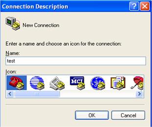
2) Type the name of the new connection in the connection description interface and click OK. The system displays the following interface. From the Connect using drop-down list, select the serial interface to be used.
Figure 4-3 Set the serial interface used for HyperTerminal connection

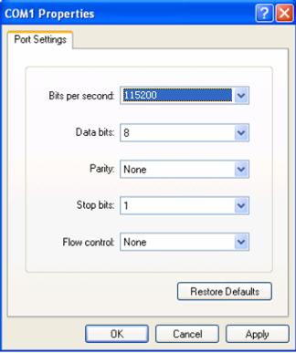
3) Click OK and the system displays the following interface. On the interface, set Bits per second to 9600, Data bits to 8, Parity to none, Stop bits to 1, and Flow control to none.
Figure 4-4 Set serial interface parameters
4) Click OK and the system displays the following interface.
Figure 4-5 HyperTerminal window
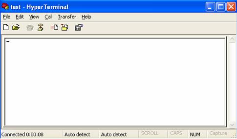
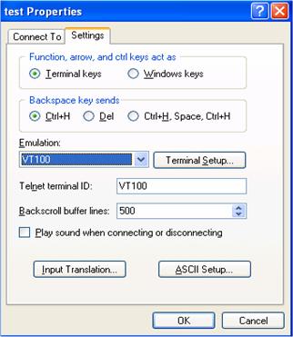
5) Set HyperTerminal properties. Select File > Properties > Settings in the HyperTerminal to enter the properties setting window, as shown in the following figure. Select the terminal emulation type as VT100 or Auto detect, and click OK to return to the HyperTerminal window.
Figure 4-6 Set terminal emulation in H3C Properties window
Powering On the AC
Checking Before Power-On
Before powering on the AC, verify that:
l The power cord is properly connected.
l The power supply voltage is within the range labeled on the AC.
l The console cable is properly connected; the terminal (for example, a PC) used for configuration has been started; the configuration parameters have been set.
Powering On the AC
The following is information output by a WX5002 AC after it is powered on and started up.
*********************************************
* *
* H3C WCM BootWare , Ver 1.16 *
* *
*******************************************
Copyright(c) 2004-2009 Hangzhou H3C Technologies Co., Ltd.
Compiled date : May 6 2009, 20:21:15
CPU type : BCM1250
CPU L1 DCache : 32KB
CPU L1 ICache : 32KB
CPU L2 Cache : 512KB
CPU Clock Speed : 700MHz
Memory Type : DDR SDRAM
Memory Size : 1024MB
Memory Speed : 140MHz
BootWare Size : 512KB
Flash Size : 32MB
NVRAM Size : 512KB
CPLD Version is 1.00
Hardware Version is Ver.B
GE0 ..............................OK!
GE1 ..............................OK!
Press Ctrl+B to enter extend boot menu... 5
The last line prompts you to enter the Boot menu.
l If you press <Ctrl + B> within 5 seconds, the program goes to the BootWare main menu. Refer to section “BootWare Main Menu” on page 5-3 for details of the BootWare main menu. If you perform no operation or press a key other than <Ctrl + B> within five seconds, the system begins to automatically start up and the following information is displayed:
The current starting file is main application file--flash:/main.bin!
The main application file is self-decompressing........................................
........................................................................................
........................................................................................
........................................................................................
........................................................................................
....................................................................OK!
System is starting...
User interface con0 is available.
Press ENTER to get started.
The prompt "Press ENTER to get started" indicates that the automatic startup of the AC is completed.
Press <Enter>. The following prompt is displayed:
<H3C>
You can configure the AC now.
![]()
H3C WX5002 AC provides various command views. For detailed information about related configuration commands and command line interfaces, refer to H3C WX Series Access Controllers User Manual and H3C WX Series Access Controllers Web-Based Configuration Manual.
Overview
Files Managed by the AC
BootWare program file
Application file
WX5002 AC support the Dual Image function. By default, the system defines three application files for booting: main, backup, and secure. If you have loaded the three application files into the Flash, the system will use these three files to boot in order. For more information about the application files, refer to section “Maintaining Application and Configuration Files in BootWare” on page 5-18.
The following gives the default names and types of the application files and their priorities for booting.
l Main application file. The default name is main.bin, and the file type is M. It is the default application file used for booting.
l Backup application file. The default name is backup.bin, and the file type is B. When the boot using the main application file fails, the system boots using the backup application file.
l Secure application file. The default name is secure.bin, and the file type is S. When boot using the backup application file fails, the system boots using the secure application file. If the boot using the secure application file fails, the system prompts a boot failure.
![]()
l The application files for system boot can be type M, B and S, but not type N/A (that is, types other than M, B, and S).
l You can modify the names of application files of type M, B and N/A except type S in the BootWare menu or using commands after the application program boots.
l The secure application file is the last resort for system boot. You cannot change the type of the secure application file, or change other types of files to the secure application file. You can only download it using the BootWare menu. If you change the name of the secure application file with the rename command after the system boots, the file is removed from the Flash. To use the secure application file, you need to download it again.
l There is only one file of the same type (M, B, or S) in the Flash. For instance, if there is a file of type M+B in the Flash, there will not be other files of type M or B. If the type of another file is changed to B, the original type M+B file changes to a file of type M.
Configuration file
The file stores configuration information of the AC.
AC Software Maintenance Methods
l Upgrade BootWare and application programs using XMODEM protocol through a serial interface.
l Upgrading application programs from TFTP server through Ethernet interface in BootWare.
l Upload/download application programs and configuration files to/from the TFTP/FTP server through command lines.
![]()
l The BootWare program is upgraded together with the host software program version. That is, the system automatically upgrades the BootWare program when you upgrade the host software program.
l Check the current version of BootWare and application programs before upgrading. For the association between the host software program version and the BootWare program version, refer to the version configuration information in Release Notes.
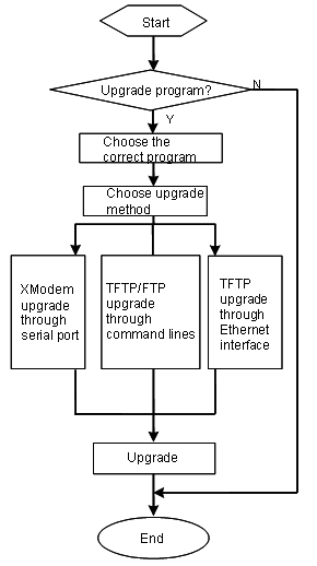
Figure 5-1 BootWare and application programs upgrade flow
BootWare Menu
BootWare Main Menu
When the AC is powered on and reboots, the following information is first displayed on the console terminal:
System starts booting ...
Then, the system prompts the following:
*********************************************
* *
* H3C WCM BootWare , Ver 1.16 *
* *
*******************************************
Copyright(c) 2004-2009 Hangzhou H3C Technologies Co., Ltd.
Compiled date : May 6 2009, 20:21:15
CPU type : BCM1250
CPU L1 DCache : 32KB
CPU L1 ICache : 32KB
CPU L2 Cache : 512KB
CPU Clock Speed : 700MHz
Memory Type : DDR SDRAM
Memory Size : 1024MB
Memory Speed : 140MHz
BootWare Size : 512KB
Flash Size : 32MB
NVRAM Size : 512KB
CPLD Version is 1.00
Hardware Version is Ver.B
GE0 ..............................OK!
GE1 ..............................OK!
Press Ctrl+B to enter extend boot menu... 5
![]()
The extend-BootWare menu is referred to as BootWare main menu in this manual unless otherwise specified.
Press <Ctrl+B> when “Press Ctrl+B to enter extend boot menu...” appears, and the system prompts:
Please input BootWare password:
You can try up to three times to type the BootWare password (the initial password is null). If you have tried three times but the password is still incorrect, you need to reboot the system. After you type the correct password, the system enters the BootWare main menu:
==================<EXTEND-BOOTWARE MENU>===================
| <1> Boot System |
| <2> Enter Serial SubMenu |
| <3> Enter Ethernet SubMenu |
| <4> File Control |
| <5> Modify BootWare Password |
| <6> Ignore System Configuration |
| <7> BootWare Operation Menu |
| <8> Clear Super Password |
| <0> Reboot |
===========================================================
Enter your choice (0-8):
The menu is described in the following table.
|
Menu item |
Description |
|
<1> Boot System |
Boot the system |
|
<2> Enter Serial SubMenu |
Enter the serial submenu. For detailed description, refer to Serial submenu. |
|
<3> Enter Ethernet SubMenu |
Enter the Ethernet submenu. For detailed description, refer to Ethernet submenu. |
|
<4> File Control |
File control submenu. For detailed description, refer to File control submenu. |
|
<5> Modify BootWare Password |
Modify the BootWare password. |
|
<6> Ignore System Configuration |
Boot the system with the system configuration ignored |
|
<7> BootWare Operation Menu |
BootWare operation submenu. For detailed description, refer to BootWare operation submenu. |
|
<8> Clear Super Password |
Clear the super password. |
|
<0> Reboot |
Reboot the AC. |
BootWare Submenus
Serial submenu
You can upgrade application programs, change the serial interface baud rate and so on through this submenu.
Select 2 in the BootWare main menu to enter the serial submenu.
======================<SERIAL SUB-MENU>======================
| <1> Download Application Program To SDRAM And Run |
| <2> Update Main Application File |
| <3> Update Backup Application File |
| <4> Update Secure Application File |
| <5> Modify Serial Interface Parameter |
| <0> Exit To Main Menu |
=============================================================
Enter your choice (0-5):
Items in this submenu are described in the following table.
Table 5-2 BootWare serial submenu
|
Menu item |
Description |
|
<1> Download Application Program To SDRAM And Run |
Download an application program to SDRAM and run the program. |
|
<2> Update Main Application File |
Upgrade the main application file. |
|
<3> Update Backup Application File |
Upgrade the backup application file. |
|
<4> Update Secure Application File |
Upgrade the secure application file. |
|
<5> Modify Serial Interface Parameter |
Modify serial interface parameters. |
|
<0> Exit To Main Menu |
Return to the BootWare main menu. |
Ethernet submenu
Select 3 in the BootWare main menu to enter the Ethernet submenu. The system displays:
====================<ETHERNET SUB-MENU>======================
| <1> Download Application Program To SDRAM And Run |
| <2> Update Main Application File |
| <3> Update Backup Application File |
| <4> Update Secure Application File |
| <5> Change Ethernet Parameter |
| <0> Exit To Main Menu |
| < Ensure The Parameter Be Modified Before Downloading! > |
=============================================================
Enter your choice (0-5):
Items in the Ethernet submenu are described in the following table.
|
Menu item |
Description |
|
<1> Download Application Program To SDRAM And Run |
Download an application program to SDRAM and run the program. |
|
<2> Update Main Application File |
Upgrade the main application file. |
|
<3> Update Backup Application File |
Upgrade the backup application file. |
|
<4> Update Secure Application File |
Upgrade the secure application file. |
|
<5> Change Ethernet Parameter |
Modify Ethernet interface parameters. |
|
<0> Exit To Main Menu |
Return to the BootWare main menu. |
File control submenu
Select 4 in the BootWare main menu to enter the file control submenu. You can view the application file types, modify file names, and delete files through the submenu.
========================<FILE CONTROL>=======================
| <1> Display All File(s) |
| <2> Set Application File Type |
| <3> Delete File |
| <0> Exit To Main Menu |
=============================================================
Enter your choice (0-3):
Items in this submenu are described in the following table.
Table 5-4 File control submenu
|
Menu item |
Description |
|
<1> Display All File(s) |
Display all files. |
|
<2> Set Application File Type |
Set the application file type. |
|
<3> Delete File |
Delete a file. |
|
<0> Exit To Main Menu |
Return to the BootWare main menu. |
BootWare operation submenu
Select 7 in the BootWare main menu to enter the BootWare operation submenu:
=====================<BOOTWARE OPERATION>====================
| <1> Backup Full BootWare |
| <2> Restore Full BootWare |
| <3> Update Full BootWare With XModem |
| <4> Update Extend BootWare With XModem |
| <5> Update Basic BootWare With XModem |
| <0> Exit To Main Menu |
=============================================================
Enter your choice (0-5):
Items in this submenu are described in the following table.
Table 5-5 BootWare operation submenu
|
Menu item |
Description |
|
<1> Backup Full BootWare |
Back up the full BootWare. |
|
<2> Restore Full BootWare |
Restore the full BootWare. |
|
<3> Update Full BootWare With XModem |
Upgrade the full BootWare using XMODEM. |
|
<4> Update Extend BootWare With XModem |
Upgrade the extended BootWare using XMODEM. |
|
<5> Update Basic BootWare With XModem |
Upgrade the basic BootWare using XMODEM. |
|
<0> Exit To Main Menu |
Return to the BootWare main menu. |
Upgrading BootWare Through a Serial Interface
Use XMODEM to upgrade BootWare through a serial interface.
Modifying Serial Interface Parameters
Sometimes, we need to make the serial interface baud rate higher to save upgrading time or make it lower to guarantee transmission reliability. This section introduces how to adjust the serial interface baud rate.
Enter the BootWare main menu and select 2 to enter the serial interface submenu, and then select 5 in the submenu to modify the baud rate. The system displays the following:
========================<BAUDRATE SET>=======================
|Note: Change The HyperTerminal's Baudrate Accordingly, |
| Press 'Enter' to exit with things untouched. |
|--------------------<Baudrate Avaliable>-------------------|
| <1> 9600(Default) |
| <2> 19200 |
| <3> 38400 |
| <4> 57600 |
| <5> 115200 |
| <0> Exit |
=============================================================
Enter Your Choice (0-5):
Select a proper baud rate. For example, select 5 for a baud rate of 115,200 bps and the system displays the following information:
Download speed is 115200 bps. Change the terminal's speed to 115200 bps,
and select XMODEM protocol. Press 'Enter' key when ready.
At this time, the baud rate of the AC serial interface is modified to 115,200 bps, while that of the terminal is still 9,600 bps. The AC and the terminal cannot communicate with each other. Change the baud rate to 115,200 bps on the terminal.
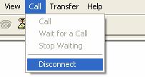
Perform the following operations on the terminal:
Figure 5-2 Disconnect the terminal
Select File > Properties, and then click Configure… to change the bits per second to 115,200.
Figure 5-3 Modify the baud rate
Select Call > Call to establish a new connection.
Figure 5-4 Re-establish a call connection

Then, press the Enter key, and the system will prompt the current baud rate and return to the previous menu.
=====================<SERIAL SUB-MENU>=====================
| <1> Download Application Program To SDRAM And Run |
| <2> Update Main Application File |
| <3> Update Backup Application File |
| <4> Update Secure Application File |
| <5> Modify Serial Interface Parameter |
| <0> Exit To Main Menu |
===========================================================
![]()
After you download files to SDRAM or upgrade application programs by changing the baud rate, restore the baud rate in the HyperTerminal to 9,600 bps in time, so as to ensure the normal display on the console screen when the system boots or reboots.
Upgrading BootWare
Enter the BootWare main menu and select 7 in the BootWare main menu (refer to section “BootWare Main Menu” on page 5-3) to enter the BootWare operation submenu where you can do all BootWare operations. Refer to section “BootWare operation submenu” on page 5-6 for details.
The following example shows how to upgrade the full BootWare:
Select 3 in the BootWare operation submenu to modify the baud rate. The system displays:
=======================<BAUDRATE SET>======================
| Note:Change The HyperTerminal's Baudrate Accordingly, |
| Press 'Enter' to exit with things untouched. |
| ------------------<Baudrate Available>------------------|
| <1> 9600(Default) |
| <2> 19200 |
| <3> 38400 |
| <4> 57600 |
| <5> 115200 |
| <0> Exit |
===========================================================
Enter your choice (0-5):
For the baud rate modification procedure, refer to section “Modifying Serial Interface Parameters” on page 5-7. After the modification succeeds, the system displays:
Download speed is 115200 bps. Change the terminal's speed to 115200 bps,
and select XMODEM protocol. Press 'Enter' key when ready.
Now Downloading Program File.
Please Start Transfer Program File And Use Xmodem Protocol.
If You Want To Exit. Press 'Ctrl+X'.
Downloading...CC
Select Transfer > Send file… in the terminal window. The following dialog box appears:
Figure 5-5 Send File dialog box
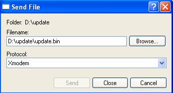
Click Browse… to select the application program to be downloaded, and select Xmodem from the Protocol drop-down list. Then click Send and the following dialog box appears:
Figure 5-6 Sending file dialog box
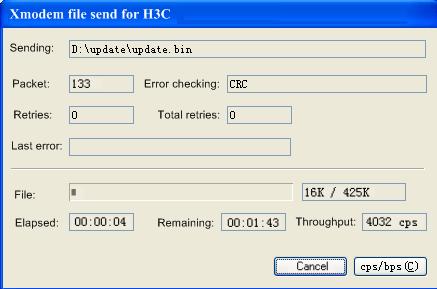
After the BootWare program file is downloaded, the following information appears on terminal interface:
Download successfully!
434432 bytes downloaded!
Updating Basic BootWare ? Yes or No (Y/N):Y
Updating Basic BTM
Updating the Norm Basic BootWare......Done
Updating Extend BootWare ? Yes or No (Y/N):Y
Updating Extend BTM
Updating Extend BootWare.......Done
Please change the terminal's speed to 9600 bps. Press 'Enter' key when ready.
Change the baud rate on the console terminal from 115,200 bps to 9,600 bps, and then reboot the AC.
![]()
l The file name, size and path in the above figure may vary. Check the current BootWare and application program versions before upgrading.
l After you download a file to upgrade BootWare by changing the baud rate, restore the baud rate in the HyperTerminal to 9,600 bps in time, so as to ensure the normal display on the console screen when the system boots or reboots.
Upgrading an Application Program Through a Serial Interface
The application program upgrade through a serial interface is implemented in the serial submenu. Select 2 in the BootWare main menu to enter the serial submenu. For detail description on this submenu, refer to section "Serial submenu” on page 5-4.
The following example shows how to upgrade the main application file:
To improve the upgrading speed, you can modify the serial interface baud rate before upgrading (refer to section “Modifying Serial Interface Parameters” on page 5-7). Select 2 in the serial interface submenu, and the system prompts:
Now Downloading Program File.
Please Start Transfer Program File And Use Xmodem Protocol.
If You Want To Exit. Press 'Ctrl+X'.
Waiting...CCC
Select the application file and click Send. The procedure for upgrading an application program through a serial interface is similar to the one for upgrading BootWare. Refer to section “Upgrading BootWare” on page 5-9.
![]()
The size of an application program is often over 10 MB. Even if the baud rate is 115,200 bps, it will take about 30 minutes to upgrade the application through a serial interface. Therefore, you are recommended to upgrade an application program through an Ethernet interface.
Upgrading an Application Program Through an Ethernet Interface
Select 3 in the BootWare main menu to enter the Ethernet submenu. For details, refer to section “Ethernet submenu” on page 5-5.
Configuring Ethernet Interface Parameters
Before upgrading an application program through an Ethernet interface, you need to configure the Ethernet interface of the AC as follows:
Select 3 in the BootWare main menu to enter the Ethernet submenu. Then, select 5 in the submenu to enter the Ethernet interface parameter configuration interface:
One protocol for download, tftp.
'.' = clear field; '-' = go to previous field; ^D = quit
boot device : eth0 Boot device name. Cannot be changed.
file name : wx5002.bin The download file name shall be
consistentwith the real file name, and you
need to designate the download path in TFTP
settings.
inet on ethernet (e) : 192.168.0.124 Set to be in the same network with TFTP
server. It has nothing to do with port IP
address of the AC.
host inet (h) : 192.168.0.179 IP address of TFTP server.
gateway inet (g) : 192.168.0.1 Gateway IP address. No need to set.
![]()
l When configuring a parameter, you can enter a new value directly, or press Enter to accept the default coming after the colon. Type the symbol “.” to clear the input, “-” to return to the previous parameter, and “^D” (namely, <Ctrl+D>) to quit from the parameter configuration interface.
l WX5002 AC can use the 10/100 BASE-TX out-of-band management interface only.
Upgrading an Application Program
Trivial File Transfer Protocol (TFTP), a protocol in TCP/IP protocol suite, is used for trivial file transfer between client and server. It provides not-so-complex and low-cost file transfer services. TFTP provides unreliable data transfer services over UDP and does not provide any access authorization and authentication mechanism. It employs timeout and retransmission to guarantee the successful delivery of data. The TFTP software is much smaller than the FTP software in size.
Step 1: Set up an upgrade environment.
Figure 5-7 Set up a TFTP upgrade environment
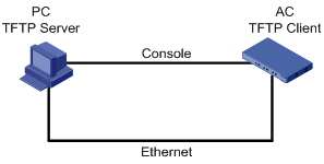
Connect the 10/100 BASE-TX out-of-band management interface to a PC with a crossover cable. Start the TFTP server on the PC, and set the TFTP server path to the directory of the application program.
![]()
The TFTP server is not provided with H3C WX5002 AC. You need to purchase and install it yourself.
Step 2: Modify Ethernet interface parameters. Refer to section “Configuring Ethernet Interface Parameters” on page 5-11 for details.
Step 3: After the above configuration, select 3 in the BootWare main menu to enter the Ethernet submenu. In the following example, select 2 to upgrade the main application file.
Starting the TFTP download.................................Done
Please input file name(Press 'Enter' use default name):
After the download is done, enter the file name to start upgrade.
........................................................................................
........................................................................................
........................................................................................
........................................................................................
................................................
Writing into Flash Succeeds.
Step 4: Select 0 to return to the BoorWare main menu. Select 1 to boot the system.
![]()
l If the input file name is the same as the one of the original file in the Flash, the system prompts “flash:/main.bin exist, overwrite?[Y/N]”. If you choose Y, the original file in the Flash will be overwritten.
l Make sure the available space on the Flash is sufficient. Or, the system prompts insufficient space:
No enough space in flash!
Writing into Flash Fails.
l The updated file will directly replace the original one of this type and become the only application file. In this example, the downloaded file main.bin replaces the original type M file and becomes the main application file.
l Refer to section “Files Managed by the AC” on page 5-1 for detailed descriptions on file types.
Maintaining Application Programs and Configurations Through Command Lines
After booting the AC normally, you can upgrade/back up application programs and back up/restore configurations through command lines.
Maintaining the AC Through the TFTP Server
In the TFTP service, H3C WX5002 AC serve as TFTP clients, while the file server serves as the TFTP server. You can enter commands on the PC to upload or download configuration files and application programs of the AC to or from the file server.
Setting up a configuration environment
First, set up a hardware environment (for the procedure, refer to section “Upgrading an Application Program” on page 5-12), and point the server path to the directory where the file is stored.
Figure 5-8 Network diagram for maintenance through command lines
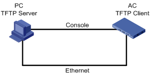
Configure the IP addresses of the two sides on the same network. For example, the IP address of the TFTP server is set to 192.168.0.1, and that of the AC is set to 192.168.0.2. Use the ping command on the TFTP server or AC to check whether the connection is successful.
Backing up and restoring application programs and configuration files
After setting up the environment, perform the following operations on the PC:
View the files included in the current file system with the dir command.
<H3C>dir
Directory of flash:/
0 -rw- 14323376 Apr 03 2006 15:36:48 main.bin
1 drw- - Mar 20 2006 09:55:28 logfile
2 -rw- 909 Apr 04 2006 10:54:38 startupbak.cfg
3 -rw- 1045 Apr 04 2006 11:31:36 startup.cfg
4 -rw- 14323376 Mar 31 2006 17:50:22 backup.bin
63340 KB total (20928 KB free)
<H3C>
Use the following command to upload the startup.cfg file from the AC to the TFTP server and save it as startup.bak.
<H3C>tftp 192.168.0.1 put startup.cfg startup.bak
File will be transferred in binary mode
Sending file to remote tftp server. Please wait... \
TFTP: 1045 bytes sent in 0 second(s).
File uploaded successfully.
Use the following command to download the startup.cfg file from the server to the AC.
<H3C>tftp 192.168.0.1 get startup.cfg startup.cfg
The file startup.cfg exists. Overwrite it?[Y/N]:y
Verifying server file...
Deleting the old file, please wait...
File will be transferred in binary mode
Downloading file from remote tftp server, please wait...\
TFTP: 1045 bytes received in 0 second(s)
File downloaded successfully.
If there already exists a startup.cfg file on the AC, the system prompts you whether to overwrite it. You can enter Y or N to confirm.
![]()
l When you back up a file, the file will directly overwrite the one with the same name on the server.
l The above operations are performed in user view.
l The backup configuration file can be modified by a text editor. You can modify the configurations by downloading the modified configuration file, and the modification takes effect after rebooting. Alike, you can upgrade the main application file by downloading a new application file to the AC to overwrite the original main application file.
Maintaining the AC Through the FTP Server
Maintaining the AC acting as the server
File Transfer Protocol (FTP) is an application layer protocol in the TCP/IP suite. It is mainly used for file transfer between remote hosts. FTP provides reliable and connection-oriented data transfer service over TCP, but does not provide any access authorization or authentication mechanism.
In the FTP service, the AC can serve as the FTP server. You can run the FTP client to log in to the AC to access files.
Install the FTP client application before using FTP. The FTP client application is not provided with the AC, and you need to purchase and install it. In the following example, the FTP client application program is the built-in Windows XP FTP client:
Step 1: Set up a hardware maintenance environment as follows:
Figure 5-9 Network diagram for maintenance of the AC serving as the server
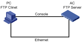
Configure the IP addresses of the two sides on the same network. In this section, the IP address of the FTP client (PC) is set to 192.168.0.1, while that of the AC is set to 192.168.0.2. You can use the ping command on the PC or AC to check whether the connection is successful.
Step 2: Enable the FTP service.
You can enable the FTP service after configuring FTP server authentication and authorization. The FTP server supports multi-client access. A remote FTP client sends a request to the FTP server. The FTP server executes an action accordingly and returns the execution result to the client. Use the following command to enable the FTP service.
[H3C]ftp server enable
% Start FTP server
Add an authorized FTP username and password.
[H3C]local-user guest Add the username guest
[H3C-luser- guest]service-type ftp Set the client type to FTP.
[H3C-luser- guest]password simple 123456 Add the password 123456 for the user guest
[H3C-luser-guest]authorization-attribute level 3 Set the user level to 3
Step 3: Maintain the AC.
After enabling the FTP service and configuring the username and password, you can enable FTP client on the PC. In the following example, the FTP client application program is the built-in Windows XP FTP client.
Type ftp in the DOS window, and the system prompt is changed to ftp>:
C:\Documents and Settings\Administrator>ftp
ftp> The system prompt is changed to ftp>
ftp> open 192.168.0.2 Connect to the AC IP address
Connected to 192.168.0.2.
220 FTP service ready.
User (192.168.0.2:(none)): guest Enter the usrname guest on the AC
331 Password required for guest
Password: Enter the password 123456
230 User logged in. The connection to the server succeeded.
Now, use the following commands to maintain the AC. In this example, the main.bin file on the AC is copied to the PC.
ftp> binary Change the transfer mode to binary
200 Type set to I.
ftp> lcd c:\temp Change the local path
Local directory now C:\temp.
ftp> get main.bin main.bin Copy the file from the AC to the PC
200 Port command okay.
150 Opening BINARY mode data connection for main.bin.
226 Transfer complete.
ftp: 14323376 bytes received in 16.81Seconds 851.87Kbytes/sec.
Use the following command to overwrite the main.bin file on the AC.
ftp> put main.bin main.bin Overwrite the file on the AC with the local backup file.
200 Port command okay.
150 Opening BINARY mode data connection for main.bin.
226 Transfer complete.
ftp: 14323376 bytes sent in 8.29Seconds 1727.37Kbytes/sec.
ftp> quit Quit FTP
221 Server closing.
Maintaining the AC acting as the client
You can also maintain the AC file system by setting up an FTP environment where the AC serves as a client.
Step 1: Set up a maintenance environment.
Figure 5-10 Network diagram for maintenance of the AC serving as a client
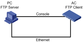
The AC serves as an FTP client, while the PC running FTP server serves as the FTP server. Set the FTP server path and add a username and password for the AC.
Configure the IP addresses of the two sides on the same network. In this section, the IP address of the FTP server is set to 192.168.0.1, and that of the AC is set to 192.168.0.2. You can use the ping command on the server or the AC to check whether the connection is successful.
Step 2: Maintain the AC through the terminal connected to the console interface of the AC.
The following gives an example:
<H3C>ftp 192.168.0.1
Trying 192.168.0.1 ...
Press CTRL+K to abort
Connected to 192.168.0.1.
220 3Com 3CDaemon FTP Server Version 2.0
User(192.168.0.1:(none)):guest Enter the username configured on the server
331 User name ok, need password
Password: Enter the corresponding password
230 User logged in Connection succeeded.
[ftp]
Use the following commands to maintain the AC after logging in.
Here again, the get and put commands are used to restore and back up files.
[ftp]get main.bin main.bin Download the file from the server to the AC
flash:/main.bin has been existing. Overwrite it?[Y/N]:y Overwrite the file
200 PORT command successful.
150 File status OK ; about to open data connection
226 Closing data connection; File transfer successful.
FTP: 14323376 byte(s) received in 69.256 second(s) 206.00K byte(s)/sec.
[ftp]put main.bin main.bin Copy the file from the AC to the server
200 PORT command successful.
150 File status OK ; about to open data connection
226 Closing data connection; File transfer successful.
FTP: 14323376 byte(s) sent in 15.974 second(s) 896.00Kbyte(s)/sec.
[ftp]quit Quit FTP
221 Service closing control connection
Maintaining Application and Configuration Files in BootWare
You can modify and display a file type in the file control submenu:
Select 4 in the BootWare main menu to enter the file control submenu. The system prompts:
========================<FILE CONTROL>=======================
| <1> Display All File(s) |
| <2> Set Application File type |
| <3> Delete File |
| <0> Exit To Main Menu |
=============================================================
Enter your choice (0-3):
Displaying all files
Select 1 in the file control submenu, and the system displays:
Display All File:
**************************************************************************
NO. Size(B) Time Name
1 4 Oct/27/2006 16:58:51 snmpboots
2 376 Oct/21/2006 14:21:24 private-data.txt
3 622 Oct/21/2006 14:21:29 startup.cfg
4 455 Oct/26/2006 10:37:06 manuinfo.txt
**************************************************************************
Setting the application file type
Select 2 in the file control submenu to set the application file type.
Please set application file type:
M=MAIN B=BACKUP S=SECURE N/A=NOT ASSIGNED
**************************************************************************
NO. Size(B) Type Time Name
1 6081128 M Oct/28/2006 09:23:30 main.bin
2 6081128 B Oct/28/2006 09:23:30 backup.bin
3 6081128 S Oct/28/2006 09:23:30 secure.bin
**************************************************************************
Enter File Name:
Enter a full file name, including the extension. For example, after you enter a full file name main.bin and press Enter, the system will prompt you to modify the file type:
Enter File Name:main.bin
Modify this file Attribute:
1. +Main
2. -Main
3. +Backup
4. -Backup
5. Exit
Enter your choice(1-5):
You can set the file type to M (main) or B (backup) or cancel the setting by selecting 1 to 4. Refer to section “Application file” on page 5-1 for details.
Deleting files
Select 3 in the file control submenu to delete files:
Delete File:
**************************************************************************
NO. Size(B) Time Name
1 4 Oct/27/2006 16:58:51 snmpboots
2 376 Oct/21/2006 14:21:24 private-data.txt
3 6081128 Oct/28/2006 09:23:30 main.bin
4 622 Oct/21/2006 14:21:29 startup.cfg
5 455 Oct/26/2006 10:37:06 manuinfo.txt
6 6081128 Oct/28/2006 09:23:30 backup.bin
7 6081128 Oct/28/2006 09:23:30 secure.bin
**************************************************************************
Enter File Name:
Enter a file name and press Enter, and then the system prompts:
Enter File Name:manuinfo.txt
flash:/manuinfo.txt will be deleted ! Continue ? [Y/N]
Enter Y to confirm the deletion, and the system prompts that the file is successfully deleted.
flash:/manuinfo.txt will be deleted ! Continue ? [Y/N]y
Deleting flash:/manuinfo.txt...OK!
Returning to the main menu
Select 0 to return to the BootWare main menu.
Dealing With Password Loss
When the BootWare password, user password or super password is lost, resort to the following methods:
User Password Loss
If you lose your password, you cannot enter the system. In this case, you can boot the system by neglecting the system configuration. Perform the following operations:
Step 1: Enter the BootWare main menu, and select 6 to boot the system by ignoring the system configuration:
The system prompts:
System startup with ignore user's configuration, Yes or No [Y/N]:y
Flag Set Successfully!
The system prompts the setting succeeds.
Step 2: When the BootWare main menu appears again, select 0 to reboot the system.
System starts booting ...
Step 3: Set a new password in system view after reboot.
[H3C]user-interface con 0
[H3C-ui-aux0]authentication-mode password
[H3C-ui-aux0]set authentication password simple 123456
The above information indicates that the password authentication is adopted at the console interface and the password is set to 123456 and stored in plain text.
![]()
l After reboot, the system runs with the initial default configuration, but the original configuration file is still stored in the Flash. To restore the original configuration, you can use the display saved-configuration command to display it, and then copy and execute it.
l If the password is stored in plain text, you can use the display current-configuration command to see the password in the current configuration. If you use the set authentication password cipher 123456 command to set a password, the password is stored in cipher text.
Step 4: Save the new password.
[H3C] save
![]()
Execute the save command after modifying the user password to save the new password.
BootWare Password Loss
Contact the agent or the technical support personnel to set a new password in the event of BootWare password loss.
You can modify the BootWare password in the BootWare main menu.
Select 5 in the BootWare main menu to modify the password. The console terminal displays:
Change password.
Old password: Enter the old password
New password: Enter a new password
Verify: Enter the new password again
........Password Set Successfully. The new password is set successfully
![]()
The password modification fails when the old password is incorrect or the new password is inconsistent, and the system will exit this operation.
Super Password Loss
The super password enables you to switch between four super levels. In the case of super password loss, you cannot perform higher level operations.
You can clear the super password by selecting 8 in the BootWare main menu.
Select this option, quit the menu, and reboot the AC, and then you can enter system view directly. This setting is valid for the first reboot of the AC only. The super password will be restored after a second reboot.
Backing Up and Restoring BootWare
Select 7 in the BootWare main menu to enter the BootWare operation submenu. Refer to section “BootWare operation submenu” on page 5-6 for details.
Select 1 in this submenu, and the system starts to back up the entire BootWare and prompts:
Backing BootWare....
Updating the backup Basic BootWare.......Done
Backing Basic BootWare Success!
Updating Back Extend BootWare..........Done
Backing Extend BootWare Success!
Now, the entire BootWare is copied to the Flash.
Select 2 in this submenu to overwrite the BootWare in the system with the backup BootWare in the Flash:
Restore Basic BootWare
Updating the Norm Basic BootWare..............Done
Restore Basic BootWare Success!
Restore Extend BootWare
Updating Extend BootWare..............Done
Restore Extend BootWare Success!
Software Loading Failure
If software loading fails, the system still runs the original version. In this case, check whether the physical interfaces are properly connected:
l If not, reconnect them correctly and restart the loading procedure.
l If so, view the loading information displayed on the HyperTerminal to check for input errors. If there is any input error, restart the loading procedure and ensure the input correctness.
l Fail to set the baud rate of the HyperTerminal to 9,600 bps when loading the software at a baud rate of 9,600 bps through XMODEM.
l Enter an incorrect IP address, software name, or path of the TFTP server when using TFTP.
l Enter an incorrect IP address, software name, username, or password when using FTP.
If software loading fails when there are neither physical connection problems nor input errors, please contact your agent for help.
Power Supply Failure
You can check whether the AC power system works normally by observing the PWR LED on the front panel. The PWR LED is ON when the power system works normally. When the PWR LED is OFF, check whether:
l The AC power cord is properly connected.
l The AC power supply meets the requirement.
Configuration System Failure
After the AC is powered on and the system is normal, the booting information will be displayed on the console terminal. If the configuration system has any faults, illegible characters or nothing will be displayed on the console terminal.
Troubleshooting when nothing is displayed
If nothing is displayed on the terminal after the AC is powered on, please check whether:
l The power supply is normal.
l The console cable is properly connected.
If the above-mentioned items ruled out, the problem may lie in the console cable or the settings of the terminal (such as HyperTerminal) parameters. Please perform the corresponding check.
Troubleshooting when illegible characters are displayed on the terminal
If illegible characters are displayed at the console terminal, the problem probably lies in the parameter settings on the terminal (such as HyperTerminal). Verify the following terminal parameter (such as HyperTerminal) settings:
l Bits per second: 9600
l Data bits: 8
l Parity: None
l Stop bits: 1
l Flow control: None
