| Title | Size | Downloads |
|---|---|---|
| H3C LSVM1BSR10 adjustable slide rails installation guide-6PW102-book.pdf | 332.01 KB |
- Table of Contents
H3C LSVM1BSR10 adjustable slide rails installation guide
1 Introduction
The H3C LSVM1BSR10 adjustable slide rails have a load-bearing capacity of 200 kg (440.92 lb). When the load is less than 100 kg (220.46 lb), you can adjust the slide rails in the range of 630 mm (24.80 in) to 900 mm (35.43 in). When the load is greater than or equal to 100 kg (220.46 lb), you can adjust the slide rails in the range of 630 mm (24.80 in) to 850 mm (33.46 in).
The H3C LSVM1BSR10 adjustable slide rails are applicable only to four-post racks. To attach the slide rails to a rack, make sure the rack depth is in the length range of the slide rails.
2 Installation procedures
The installation of slide rails might vary by rack type. The following installation procedure is for your reference only.
To install a slide rail:
1. Read the signs on the slide rail to avoid making a mistake.
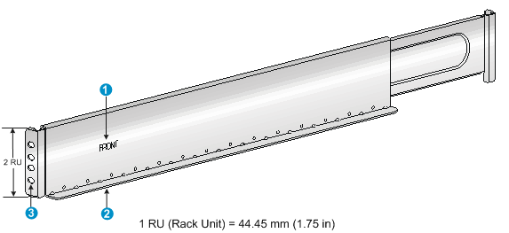
|
(1) Sign |
(2) Guide rail |
(3) Installation hole |
2. Mark the position on the rack for installing the slide rail, as shown in Figure 2 .
Ensure that the installation holes on the slide rail are aligned with the square holes on the rack post.
b. Each rack post requires four screws to fix the slide rail. You only need to mark the uppermost square hole and lowermost square hole for installation.
c. Mark the square holes at the same height on the other three rack posts.
Figure 2 Locating the rack position for installing slide rails
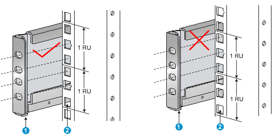
|
(1) Positioning tab |
(2) Lowest square hole within the 2U space on the rack post |
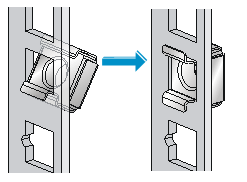
3. Install four cage nuts on the square holes on each rack post, as shown in Figure 3 .
Figure 3 Installing a cage nut
4. Perform the following tasks as shown in Figure 4 :
a. Align the installation holes on the front end of the slide rail with the cage nuts on the front rack post.
b. Compress the slide rail, making sure the positioning tabs at both ends of the slide rail are inserted into the lowest square holes within the 2U space on the rack posts.
c. Use screws to secure the slide rail to the rack posts.
Figure 4 Attaching the slide rail to the cage nuts with screws
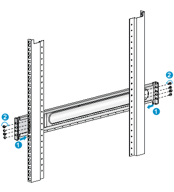
|
(1) Compress the slide rail, making sure the positioning tabs are inserted into the square holes |
|
|
(2) Install fastening screws |
|
|
|
TIP: Install a screw in each mounting hole of the slide rail to ensure its weight bearing capacity. |
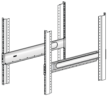
5. Repeat steps 4 and 5 to install the other slide rail. Make sure the two slide rails are at the same height so the device can be placed on them horizontally.
Figure 5 Installed slide rails
Copyright © 2017 New H3C Technologies Co., Ltd.
