| Title | Size | Downloads |
|---|---|---|
| H3C S7500E Series Ethernet Switches Software Upgrade Guide(V1.02)-book.pdf | 296.85 KB |
- Table of Contents
Software upgrade
|
|
CAUTION: Upgrade software only when necessary and under the guidance of a technical support engineer. |
Software used for upgrade
Boot ROM images
Boot ROM images are used to upgrade the Boot ROM program of cards, including the main processing units (MPUs) and line processing units (LPUs). A Boot ROM image is a .btw file.
System software images
System software images are used at switch startup. The S7500E series support two types of system software image:
· Main system software image—The default system software image a switch uses for startup.
· Backup system software image—The system software image a switch uses for startup when the main system software image is invalid or does not exist.
|
|
NOTE: Generally, there is no need to upgrade the Boot ROM program independently. The device uses the shipped Boot ROM program. If a separate upgrade is required, do that under the guidance of an H3C technical support engineer. |
Patch package file
Patches for the S7500E switches are released in a patch package file.
A patch package file fixes certain software defects. It contains patch files for multiple cards. It enables you to use one command to bulk-fix bugs for multiple cards.
A patch package file corresponds to the system software image version. A patch package file can only fix defects of the corresponding system software image file, but does not add or delete any functions.
Upgrade methods
You can upgrade switch software by using one of the following methods:
|
Upgrade mode |
Object |
Remarks |
|
· Boot ROM · System software |
· Reboot the switch to validate the upgrade. · This method interrupts services. |
|
|
Patches |
This method does not interrupt services, and fixes the target system software only. |
|
|
· Boot ROM · System software |
This method can be used when the switch cannot start up. |
|
|
NOTE: · The S7500E switch series supports In-Service Software Upgrade (ISSU). ISSU can avoid service interruption during software upgrade. For more information about ISSU, see Fundamentals Configuration Guide in S7500E Series Ethernet Switches Configuration Guides. · H3C recommends you to upgrade software from the CLI when your switch operates properly. · To make sure the active and standby MPUs use the same software version, upgrade them by using the same method. · Make sure the system software and Boot ROM are compatible. For the compatibility between the system software and Boot ROM, see the hardware and software compatibility matrix in the Release Notes. · You can upgrade the Boot ROM for the LPUs from the CLI only. · The command outputs in this document are for reference only. |
Upgrade from the CLI
The upgrade procedure on a standalone switch is different from that on an Intelligent Resilient Framework (IRF) fabric. This section describes the following topics:
· Upgrading a standalone switch
|
|
NOTE: S7500E switches can form a single IRF fabric. For more information about IRF, see the IRF Configuration Guide in the H3C S7500E Switch Series Configuration Guides. |
Upgrading a standalone switch
Upgrade prerequisites
# Telnet to the switch or log in through the console port.
# Display device information.
<Sysname> display device
Slot No. Brd Type Brd Status Subslot Num Sft Ver Patch Ver
0 LSQ1SRP1CB Master 0 S7500E None
1 LSQ1SRP1CB Slave 0 S7500E None
2 NONE Absent 0 NONE None
3 LSQ1GV48SC Normal 0 S7500E None
4 LSQ1TGX1EA Normal 0 S7500E None
The output shows that the switch has two MPUs, an active MPU in slot 0 and a standby MPU in slot 1. You must upgrade software for the two MPUs.
|
|
NOTE: You only need to upgrade the active MPU if the device has no standby MPU. |
# Examine the free storage space on the active and standby MPUs.
· On the active MPU
<Sysname> dir
Directory of flash:/
0 -rw- 3597 Sep 01 2009 18:35:28 startup.cfg
1 -rw- 6625 Jun 02 2010 16:50:51 switch.cfg
2 -rw- 27475851 Aug 11 2010 11:04:20 switch001.app
3 -rw- 31782388 Jul 23 2010 09:25:21 switch002.app
64389 KB total (5636 KB free)
· On the standby MPU
<Sysname> dir slot1#flash:/
Directory of slot1#flash:/
0 -rw- 3597 Sep 01 2009 18:35:28 startup.cfg
1 -rw- 6625 Jun 02 2010 16:50:51 switch.cfg
2 -rw- 27475851 Aug 11 2010 11:04:20 switch001.app
3 -rw- 31782388 Jul 23 2010 09:25:21 switch002.app
64389 KB total (5636 KB free)
Verify that the free storage space is sufficient for the new .app file. You can delete undesired files with the delete /unreserved command to free storage space.
# Delete undesired files from the active and standby MPUs.
· On the active MPU
<Sysname> delete /unreserved flash:/switch001.app
The content cannot be restored!!!
Delete flash:/switch001.app?[Y/N]:y
Deleting a file permanently will take a long time. Please wait...
%Delete file flash:/switch001.app...Done.
· On the standby MPU
<Sysname> delete /unreserved slot1#flash:/switch001.app
The content cannot be restored!!!
Delete slot1#flash:/switch001.app?[Y/N]:y
Deleting a file permanently will take a long time. Please wait...
%Delete file slot1#flash:/switch001.app...Done.
|
|
NOTE: · The delete /unreserved file-url command deletes a file permanently and the action cannot be undone. · The delete file-url command moves a file to the recycle bin and the file still occupies storage space. To permanently delete the file from the recycle bin, execute the reset recycle-bin command in the original directory of the file. |
Downloading the .app file to the switch
Download the .app file to the storage medium (such as flash memory) of the active MPU and that of the standby MPU. Skip this section if the file is already located there.
You can download the .app file through FTP or TFTP. The following illustrates how to download through FTP when the switch serves as the FTP client and a PC serves as the FTP server.
1. Run the FTP server program on the PC (assume its IP address is 10.10.110.1) and configure the username, password, and file storage directory.
2. Download the .app file (newest.app for example) to the active MPU of the switch.
# Log in to the PC through FTP.
<Sysname> ftp 10.10.110.1
Trying ...
Press CTRL+K to abort
Connected to 10.10.110.1
220 3Com 3CDaemon FTP Server Version 2.0
User(10.10.110.1:(none)):username ---Type the username.
331 User name ok, need password
Password: ---Enter the password.
230 User logged in
# Set the file transfer mode to binary.
[ftp] binary
200 Type set to I.
# Download the .app file from the PC to the root directory of the storage medium on the active MPU.
[ftp] get newest.app
227 Entering Passive Mode (10,10,110,1,17,97).
125 BINARY mode data connection already open, transfer starting for /newest.app
226 Transfer complete.
FTP: 28945856 byte(s) received in 35.974 second(s), 896.00K byte(s)/sec.
[ftp] bye
221 Server closing.
3. Copy the .app file to the standby MPU of the switch.
# Copy the file newest.app to the root directory of the storage medium on the standby MPU in slot 1.
<Sysname> copy newest.app slot1#flash:/
Copy flash:/newest.app to slot1#flash:/newest.app?[Y/N]:y
%Copy file flash:/newest.app to slot1#flash:/newest.app...Done.
|
|
NOTE: · You can configure the switch as the FTP server, FTP client, or TFTP client. The transfer processes slightly vary. For more information about FTP and TFTP, see Fundamentals Configuration Guide in H3C S7500E Series Ethernet Switches Configuration Guides. · You can use the transfer procedure described in this section to transfer Boot ROM images, system software images, and patch files for upgrade from the CLI. |
Upgrading software from the CLI
|
|
CAUTION: Make sure the .app file exists in the root directory of the storage medium of the active MPU and the standby MPU. |
Perform the following tasks as needed:
# Upgrade the Boot ROM for the active MPU in slot 0.
<Sysname> bootrom update file flash:/newest.btw slot 0
This command will update bootrom file on the specified board(s),
Continue? [Y/N]:y
Now updating bootrom, please wait...
Start accessing bootflash chip...
Bootrom update succeeded in slot 0.
# Upgrade the Boot ROM for the standby MPU in slot 1.
<Sysname> bootrom update file slot1#flash:/newest.btw slot 1
This command will update bootrom file on the specified board(s),
Continue? [Y/N]:y
Now updating bootrom, please wait...
Start accessing bootflash chip...
Bootrom update succeeded in slot 1.
# Upgrade the Boot ROM for the LPU in slot 3.
<Sysname> bootrom update file flash:/newest.btw slot 3
This command will update bootrom file on the specified board(s),
Continue? [Y/N]:y
Now updating bootrom, please wait...
Board has finished loading file on Chassis 0 Slot 3.
Start accessing bootflash chip...
Bootrom update succeeded in slot 3.
# Upgrade the Boot ROM for the LPU in slot 4.
<Sysname> bootrom update file flash:/newest.btw slot 4
This command will update bootrom file on the specified board(s),
Continue? [Y/N]:y
Now updating bootrom, please wait...
Board has finished loading file on Chassis 0 Slot 4.
Start accessing bootflash chip...
Bootrom update succeeded in slot 4.
# Reboot the switch to validate the upgrade.
<Sysname> reboot
Start to check configuration with next startup configuration file, please wait.
........DONE!
This command will reboot the device. Continue? [Y/N]:y
|
|
NOTE: The Boot ROM image stored on the active MPU can be used to upgrade both the active MPU and LPUs, while that stored on the standby MPU is used to upgrade the standby MPU only. |
# Specify the file newest.app as the main system software image to be used at the next startup of the active MPU.
<Sysname> boot-loader file flash:/newest.app slot 0 main
This command will set the boot file of the specified board. Continue? [Y/N]:y
The specified file will be used as the main boot file at the next reboot on slot 0!
# Specify the file newest.app as the main system software image to be used at the next startup of the standby MPU.
<Sysname> boot-loader file slot1#flash:/newest.app slot 1 main
This command will set the boot file of the specified board. Continue? [Y/N]:y
The specified file will be used as the main boot file at the next reboot on slot 1!
# Reboot the switch to validate the upgrade.
<Sysname> reboot
Start to check configuration with next startup configuration file, please wait.
........DONE!
This command will reboot the device. Continue? [Y/N]:y
|
|
CAUTION: · To prevent configuration loss, save the latest configuration changes before you reboot the switch. · System software images must be saved in the root directory of the storage medium. You can copy or move system software images to the root directory. For more information about the boot-loader command, see Fundamentals Command Reference in the H3C S7500E Series Ethernet Switches Command References. |
# Download the patch package file to the root directory of the storage medium of the active MPU and that of the standby MPU, and then install the patch package file with the patch install command.
<Sysname> system-view
[Sysname] patch install flash:
Patches will be installed. Continue? [Y/N]:y
Do you want to continue running patches after reboot? [Y/N]:y
Installing patches........
Installation completed, and patches will continue to run after reboot.
|
|
NOTE: · A patch file must have a valid name. Otherwise, the system cannot identify and install it. Table 1 shows the default names of patch files. · For more information about patch installation, see Fundamentals Configuration Guide in H3C S7500E Series Ethernet Switches Configuration Guides. |
Table 1 Patch files for different types of cards
|
Card type |
Default patch file name |
|
MPU |
patch_mpu.bin |
|
LPU |
patch_lpu.bin |
|
Auxiliary CPU on a LPU |
patch_lpo.bin |
Upgrading an IRF fabric
Upgrade prerequisites
# Telnet to the switch or log in through the console port.
# Display device information.
<Sysname> display device
Chassis Slot Type State Subslot Soft Ver Patch Ver
1 0 LSQ1SRP1CB Master 0 S7500E None
1 1 LSQ1SRP1CB Slave 0 S7500E None
1 2 LSQ1TGX4SD Normal 0 S7500E None
1 3 LSQ1TGX4SD Normal 0 S7500E None
1 4 LSQ1TGX4SD Normal 0 S7500E None
2 0 LSQ1SRP1CB Slave 0 S7500E None
2 1 LSQ1SRP1CB Slave 0 S7500E None
2 2 LSQ1TGX4SD Normal 0 S7500E None
2 3 LSQ1GV48SA Normal 0 S7500E None
2 4 LSQ1TGX4SD Normal 0 S7500E None
The output shows that two switches form an IRF fabric. The following table shows the MPU information.
Table 2 MPU information of the IRF fabric
|
MPU |
Member ID |
Slot number |
|
Active MPU of the IRF fabric |
1 |
0 |
|
Standby MPU of the IRF fabric |
1 |
1 |
|
Standby MPU of the IRF fabric |
2 |
0 |
|
Standby MPU of the IRF fabric |
2 |
1 |
# Check the free storage space of the active and standby MPUs on the IRF fabric.
· On the active MPU of the IRF fabric
<Sysname> dir
Directory of flash:/
0 -rw- 3597 Sep 01 2009 18:35:28 startup.cfg
1 -rw- 6625 Jun 02 2010 16:50:51 switch.cfg
2 -rw- 27475851 Aug 11 2010 11:04:20 switch001.app
3 -rw- 31782388 Jul 23 2010 09:25:21 switch002.app
64389 KB total (5636 KB free)
· On the standby MPU in slot 1 of member device 1
<Sysname> dir chassis1#slot1#flash:/
Directory of chassis1#slot1#flash:/
0 -rw- 3597 Sep 01 2009 18:35:28 startup.cfg
1 -rw- 6625 Jun 02 2010 16:50:51 switch.cfg
2 -rw- 27475851 Aug 11 2010 11:04:20 switch001.app
3 -rw- 31782388 Jul 23 2010 09:25:21 switch002.app
64389 KB total (5636 KB free)
· On the standby MPU in slot 0 of member device 2
<Sysname> dir chassis2#slot0#flash:/
Directory of chassis2#slot0#flash:/
0 -rw- 3597 Sep 01 2009 18:35:28 startup.cfg
1 -rw- 6625 Jun 02 2010 16:50:51 switch.cfg
2 -rw- 27475851 Aug 11 2010 11:04:20 switch002.app
64389 KB total (31788 KB free)
· On the standby MPU in slot 1 of member device 2
<Sysname> dir chassis2#slot1#flash:/
Directory of chassis2#slot1#flash:/
0 -rw- 3597 Sep 01 2009 18:35:28 startup.cfg
1 -rw- 6625 Jun 02 2010 16:50:51 switch.cfg
2 -rw- 27475851 Aug 11 2010 11:04:20 switch002.app
64389 KB total (31788 KB free)
Verify that the free storage space is sufficient for the files used for upgrade. You can delete undesired files with the delete/unreserved command to free storage space.
# Delete undesired files from the active and standby MPUs of the IRF fabric.
· On the active MPU of the IRF fabric
<Sysname> delete /unreserved flash:/switch001.app
The content cannot be restored!!!
Delete flash:/switch001.app?[Y/N]:y
Deleting a file permanently will take a long time. Please wait...
%Delete file flash:/switch001.app...Done.
· On the standby MPU in slot 1 of member device 1
<Sysname> delete /unreserved chassis1#slot1#flash:/switch001.app
The content cannot be restored!!!
Delete file chassis1#slot1#flash:/switch001.app?[Y/N]:y
Deleting a file permanently will take a long time. Please wait...
%Delete file chassis1#slot1#flash:/switch001.app...Done.
|
|
NOTE: · The delete /unreserved file-url command deletes a file permanently and the action cannot be undone. · The delete file-url command moves a file to the recycle bin and the file still occupies storage space. To permanently delete the file from the recycle bin, execute the reset recycle-bin command in the original directory of the file. |
Downloading the .app file to the IRF fabric
Download the .app file to the storage medium (such as flash memory) of the active MPU and that of each standby MPU of the IRF fabric. Skip this section if the file is already located there.
You can download the .app file through FTP or TFTP. The following illustrates how to download through FTP when the switch serves as the FTP client and the PC serves as the FTP server.
1. Run the FTP server program on the PC (assume its IP address is 10.10.110.1). Make sure you have configured the username and password, set the correct file directory, and saved the .app file in the work directory.
2. Download the .app file (newest.app for example) to the active MPU of the IRF fabric.
# Log in to the PC through FTP.
<Sysname> ftp 10.10.110.1
Trying ...
Press CTRL+K to abort
Connected to 10.10.110.1
220 3Com 3CDaemon FTP Server Version 2.0
User(10.10.110.1:(none)):username ---Type the username.
331 User name ok, need password
Password: ---Enter the password.
230 User logged in
# Set the file transfer mode to binary.
[ftp] binary
200 Type set to I.
# Download the .app file from the PC to the root directory of the storage medium on the active MPU of the IRF fabric.
[ftp] get newest.app
227 Entering Passive Mode (10,10,110,1,17,97).
125 BINARY mode data connection already open, transfer starting for / newest.app.
226 Transfer complete.
FTP: 14323376 byte(s) received in 15.974 second(s), 896.00K byte(s)/sec.
[ftp] bye
221 Server closing.
3. Copy the file newest.app to the root directory of the storage medium on each standby MPU of the IRF fabric.
? On the standby MPU in slot 1 of member device 1
<Sysname> copy newest.app chassis1#slot1#flash:/
Copy flash:/newest.app to chassis1#slot1#flash:/newest.app?[Y/N]:y
%Copy file flash:/newest.app to chassis1#slot1#flash:/newest.app...Done.
? On the standby MPU in slot 0 of member device 2
<Sysname> copy newest.app chassis2#slot0#flash:/
Copy flash:/newest.app to chassis2#slot0#flash:/newest.app?[Y/N]:y
%Copy file flash:/newest.app to chassis2#slot0#flash:/newest.app...Done.
? On the standby MPU in slot 1 of member device 2
<Sysname> copy newest.app chassis2#slot1#flash:/
Copy flash:/newest.app to chassis2#slot1#flash:/newest.app?[Y/N]:y
%Copy file flash:/newest.app to chassis2#slot1#flash:/newest.app...Done.
|
|
NOTE: · You can configure the switch as the FTP server, FTP client, or TFTP client. The transfer processes slightly vary. For more information about FTP and TFTP, see Fundamentals Configuration Guide in the H3C S7500E Series Ethernet Switches Configuration Guides. · You can use the transfer procedure described in this section to transfer Boot ROM images, system software images, and patch files for upgrade from the CLI. |
Upgrading software from the CLI
|
|
NOTE: Make sure the upgrade files exist in the root directory of the storage medium of the active and standby MPUs of the IRF fabric. |
Perform the following tasks as needed:
· Install a patch package file
1. Upgrade Boot ROM
# Upgrade the Boot ROM program of the active MPU of the IRF fabric.
<Sysname> bootrom update file flash:/newest.btw chassis 1 slot 0
This command will update bootrom file on the specified board(s),
Continue? [Y/N]:y
Now updating bootrom, please wait...
Start accessing bootflash chip...
Bootrom update succeeded in chassis 1 slot 0.
# Upgrade the Boot ROM program of each standby MPU of the IRF fabric.
? On the standby MPU in slot 1 of member device 1
<Sysname> bootrom update file chassis1#slot1#flash:/newest.btw chassis 1 slot 1
This command will update bootrom file on the specified board(s), Continue? [Y/N]:y
Now updating bootrom, please wait...
Start accessing bootflash chip...
Bootrom update succeeded in chassis 1 slot 1.
? On the standby MPU in slot 0 of member device 2
<Sysname> bootrom update file chassis2#slot0#flash:/newest.btw chassis 2 slot 0
This command will update bootrom file on the specified board(s), Continue? [Y/N]:y
Now updating bootrom, please wait...
Start accessing bootflash chip...
Bootrom update succeeded in chassis 2 slot 0.
? On the standby MPU in slot 1 of member device 2
<Sysname> bootrom update file chassis2#slot1#flash:/newest.btw chassis 2 slot 1
This command will update bootrom file on the specified board(s), Continue? [Y/N]:y
Now updating bootrom, please wait...
Start accessing bootflash chip...
Bootrom update succeeded in chassis 2 slot 1.
# Reboot the IRF fabric to validate the upgrade.
<Sysname> reboot
Start to check configuration with next startup configuration file, please wait.
........DONE!
This command will reboot the device. Continue? [Y/N]:y
|
|
NOTE: · You cannot upgrade the Boot ROM program of the LPUs on the member switches of an IRF fabric. · The Boot ROM image stored on the active MPU of the IRF fabric can be used to upgrade the active MPU and LPUs of the IRF fabric, while that stored on a standby MPU of the IRF fabric can be used to upgrade the standby MPU only. |
2. Upgrade system software
# Specify the file newest.app as the main system software image to be used at the next startup of the active MPU of the IRF fabric.
<Sysname> boot-loader file newest.app chassis 1 slot 0 main
This command will set the boot file of the specified board. Continue? [Y/N]:y
The specified file will be used as the main boot file at the next reboot on chassis 1 slot 0!
# Specify the file newest.app as the main system software image to be used at the next startup of the standby MPUs of the IRF fabric.
? On the standby MPU in slot 1 of member device 1
<Sysname> boot-loader file chassis1#slot1#flash:/newest.app chassis 1 slot 1 main
This command will set the boot file of the specified board. Continue? [Y/N]:y
The specified file will be used as the main boot file at the next reboot on chassis 1 slot 1!
? On the standby MPU in slot 0 of member device 2
<Sysname> boot-loader file chassis2#slot0#flash:/newest.app chassis 2 slot 0 main
This command will set the boot file of the specified board. Continue? [Y/N]:y
The specified file will be used as the main boot file at the next reboot on chassis 2 slot 0!
? On the standby MPU in slot 1 of member device 2
<Sysname> boot-loader file chassis2#slot1#flash:/newest.app chassis 2 slot 1 main
This command will set the boot file of the specified board. Continue? [Y/N]:y
The specified file will be used as the main boot file at the next reboot on chassis 2 slot 1!
# Reboot the IRF fabric to validate the upgrade.
<Sysname> reboot
Start to check configuration with next startup configuration file, please wait.
........DONE!
This command will reboot the device. Continue? [Y/N]:y
|
|
CAUTION: · To prevent configuration loss, save the latest configuration changes before you reboot the switch. · System software images must be saved in the root directory of the storage medium. You can copy or move system software images to the root directory. For more information about the boot-loader command, see Fundamentals Command Reference in the H3C S7500E Series Ethernet Switches Command References. |
3. Install a patch package file
# Download the patch package file to the root directory of the storage medium of the active and standby MPUs, and then install the patch package file with the patch install command.
<Sysname> system-view
[Sysname] patch install flash:
Patches will be installed. Continue? [Y/N]:y
Do you want to continue running patches after reboot? [Y/N]:y
Installing patches........
Installation completed, and patches will continue to run after reboot.
|
|
NOTE: · A patch file must have a valid name. Otherwise, the system cannot identify and install it. Table 1 shows the default names of patch files. · For more information about patch installation, see Fundamentals in the H3C S7500E Series Ethernet Switches Configuration Guides. |
Upgrade from the boot menu
You can upgrade the Boot ROM program and system software image for the MPUs from the boot menu.
· Upgrading Boot ROM from the boot menu
· Upgrading system software from the boot menu
|
|
CAUTION: You cannot simultaneously upgrade the active and standby MPUs from the boot menu. To make sure the active and standby MPUs use the same software version, upgrade them in turn. |
Boot menu
Connect a configuration terminal such as a PC to the console port of the switch with a console cable, run the terminal emulation program on the PC, and power on the switch.
Upon power-on, the switch runs the Boot ROM program first and displays the following information:
Starting......
RAMLine.....OK
System is booting................
****************************************************************
* *
* BOOTROM, Version 3.01 *
* *
****************************************************************
Creation Date : Aug 9 2010
CPU Type : BCM1125H
CPU L1 Cache : 32KB
CPU Clock Speed : 600MHz
Memory Type : DDR SDRAM
Memory Size : 512MB
Memory Speed : 133MHz
BootRom Size : 512KB
Flash Size : 64MB
CPLD Version : 006
PCB Version : Ver.B
Mac Address : 0023895F954F
Press Ctrl+B to enter Boot Menu...2
|
|
NOTE: · To enter the boot menu, press Ctrl+B within 5 seconds when you see "Press Ctrl+B to enter Boot Menu..." If you failed to do so, restart the switch and try again. · The output varies with switch models. |
Press Ctrl+B. The system prompts you to enter the Boot ROM password:
Please input BootRom password:
Enter the password and the boot menu appears.
|
|
CAUTION: If you change the Boot ROM password, keep in mind the latest Boot ROM password. |
BOOT MENU
1. Download application file to device
2. Select application file to boot
3. Display all files in device
4. Delete file from device
5. Modify BootRom password
0. Reboot
Enter your choice(0-5):
Upgrading Boot ROM from the boot menu
Upgrade the Boot ROM program from the boot menu by using one of the following methods:
· Using TFTP through the management Ethernet port
· Using FTP through the management Ethernet port
· Using Xmodem through the console port
· Using an upgrade file on the switch
Using TFTP through the management Ethernet port
1. Connect the management Ethernet port of the switch to the PC that stores the target .app file (the IP address of the PC is required), and connect the console port of the switch to the same or another PC.
2. Run the TFTP server program on the PC connected to the management Ethernet port and specify the file storage directory.
3. Run the terminal emulation program on the PC connected to the console port. Start the switch, enter the boot menu (see Boot menu for more information), and press Ctrl+U when you see "Enter your choice(0-5):" to enter the Boot ROM update menu.
BootRom update menu:
1. Set TFTP protocol parameters
2. Set FTP protocol parameters
3. Set XMODEM protocol parameters
4. Update through file in device
0. Return to boot menu
Enter your choice(0-4):
4. In the Boot ROM update menu, type 1 to set the TFTP parameters.
BootRom update menu:
1. Set TFTP protocol parameters
2. Set FTP protocol parameters
3. Set XMODEM protocol parameters
4. Update through file in device
0. Return to boot menu
Enter your choice(0-4):1
Load File name :newest.btw The name of the target .btw file
Switch IP address :10.10.10.2 The IP address of the switch
Server IP address :10.10.10.3 The IP address of the PC that stores the .btw file
|
|
NOTE: The switch must be on the same network segment as the PC storing the upgrade files. |
5. After you set the TFTP parameters and press Enter, the switch starts to download the upgrade file. When the file is successfully downloaded, the following output appears:
Loading...........done!
Will you Update Basic BootRom? (Y/N):
6. Answer Y to the question. The following information appears:
Will you Update Basic BootRom? (Y/N):Y
Updating Basic BootRom..........done!
Updating extended BootRom? (Y/N):
7. Answer Y to the question. The following information appears:
Updating extended BootRom? (Y/N):Y
Updating extended BootRom...........done!
BootRom update menu:
1. Set TFTP protocol parameters
2. Set FTP protocol parameters
3. Set XMODEM protocol parameters
4. Update through file in device
0. Return to boot menu
Enter your choice(0-4):
8. Type 0 to return to the boot menu.
BOOT MENU
1: Download application file to device
2: Select application file to boot
3: Display all files in device
4: Delete file from device
5: Modify bootrom password
0: Reboot
Enter your choice(0-5):0
9. Type 0 to reboot the switch.
|
|
NOTE: The new Boot ROM version takes effect after the reboot. |
Using FTP through the management Ethernet port
1. Connect the management Ethernet port of the switch to the PC that stores the target .app file (the IP address of the PC is required), and connect the console port of the switch to the same or another PC.
2. Run the FTP server program on the PC connected to the management Ethernet port, specify the file storage directory, and set the username and password.
3. Run the terminal emulation program on the PC connected to the console port. Start the switch, enter the boot menu (see Boot menu for more information), and press Ctrl+U when you see "Enter your choice(0-5):" to enter the Boot ROM update menu.
BootRom update menu:
1. Set TFTP protocol parameters
2. Set FTP protocol parameters
3. Set XMODEM protocol parameters
4. Update through file in device
0. Return to boot menu
Enter your choice(0-4):
4. In the Boot ROM update menu, type 2 to set the FTP parameters:
BootRom update menu:
1. Set TFTP protocol parameters
2. Set FTP protocol parameters
3. Set XMODEM protocol parameters
4. Update through file in device
0. Return to boot menu
Enter your choice(0-4):2
Load File name :newest.btw The name of the target .btw file
Switch IP address :10.10.10.2 The IP address of the switch
Server IP address :10.10.10.3 The IP address of the PC that stores the .btw file
FTP User Name :username The FTP username
FTP User Password :12345 The password
|
|
NOTE: The switch must be on the same network segment as the PC storing the upgrade files. |
5. After you set the FTP parameters and press Enter, the switch starts to download the upgrade file. When the file is successfully downloaded, the following information appears:
Loading...........done!
Will you Update Basic BootRom? (Y/N):
6. Answer Y to the question. The following information appears:
Will you Update Basic BootRom? (Y/N):Y
Updating Basic BootRom..........done!
Updating extended BootRom? (Y/N):
7. Answer Y to the question. The following information appears:
Updating extended BootRom? (Y/N):Y
Updating extended BootRom...........done!
BootRom update menu:
1. Set TFTP protocol parameters
2. Set FTP protocol parameters
3. Set XMODEM protocol parameters
4. Update through file in device
0. Return to boot menu
Enter your choice(0-4):
8. Type 0 to return to the boot menu.
BOOT MENU
1: Download application file to device
2: Select application file to boot
3: Display all files in device
4: Delete file from device
5: Modify bootrom password
0: Reboot
Enter your choice(0-5):0
9. Type 0 to reboot the switch.
|
|
NOTE: The Boot ROM upgrade takes effect at the next startup. |
Using Xmodem through the console port
1. Connect the console port of the switch to the PC that stores the upgrade files.
2. Run the terminal emulation program on the PC. Start the switch, enter the boot menu (see Boot menu for more information), and press Ctrl+U when you see "Enter your choice(0-5):" to enter the Boot ROM update menu.
BootRom update menu:
1. Set TFTP protocol parameters
2. Set FTP protocol parameters
3. Set XMODEM protocol parameters
4. Update through file in device
0. Return to boot menu
Enter your choice(0-4):
3. In the Boot ROM update menu, type 3 to set the Xmodem parameters:
BootRom update menu:
1. Set TFTP protocol parameters
2. Set FTP protocol parameters
3. Set XMODEM protocol parameters
4. Update through file in device
0. Return to boot menu
Enter your choice(0-4):3
Please select your download baudrate:
1.*9600
2. 19200
3. 38400
4. 57600
5. 115200
0. Exit
Enter your choice (0-5):2
4. Select an appropriate download baud rate. For example, type 2 to select 19200 bps. The following information appears:
Please change the terminal's baudrate to 19200 bps and select XMODEM protocol.
Press ENTER key when ready.
|
|
NOTE: If you want to use the baud rate of 9600 bps, select it and directly go to Step 7. In this case, the system does not display the above information. |
5. Disconnect HyperTerminal from the switch by clicking Disconnect in the HyperTerminal window.
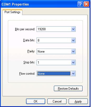
6. Select File > Properties in the HyperTerminal window, click Configure in the popup dialog box, and select the baud rate of 19200 bps in the console port properties dialog box.
Figure 1 The Switch Properties dialog box
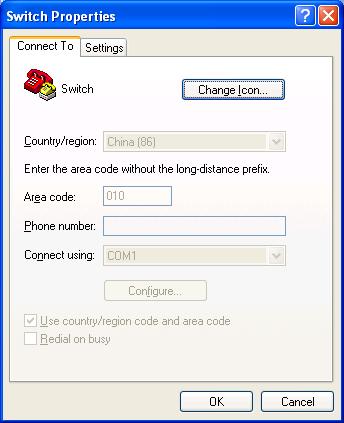
Figure 2 The console port properties dialog box
7. Click Connect to re-connect to the switch. The following information appears:
Now please start transfer file with XMODEM protocol.
If you want to exit, Press <Ctrl+X>
Downloading ...CCCCCCCCCCCCCCC
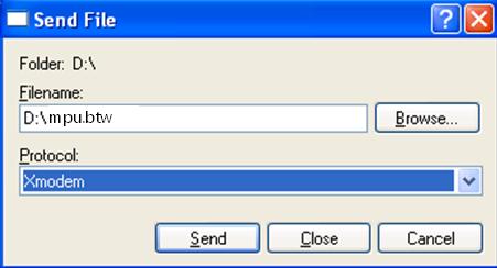
8. Select Transfer > Send File in the HyperTerminal window. In the Send File dialog box that appears, click Browse to select the target .app file, and select Xmodem as the protocol.
Figure 3 The Send File dialog box
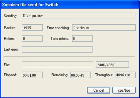
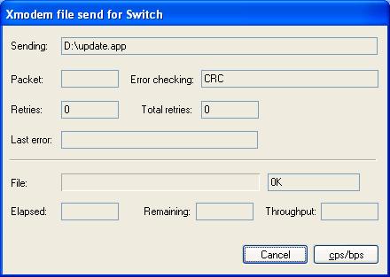
9. Click Send. The following dialog box appears:
Figure 4 The Xmodem file send for Switch dialog box
10. When the file is successfully downloaded, the following information appears:
Loading...........done!
Will you Update Basic BootRom? (Y/N):
11. Answer Y to the question. The following information appears:
Will you Update Basic BootRom? (Y/N):Y
Updating Basic BootRom..........done!
Updating extended BootRom? (Y/N):
12. Answer Y to the question. The following information appears:
Updating extended BootRom? (Y/N):Y
Updating extended BootRom...........done!
BootRom update menu:
1. Set TFTP protocol parameters
2. Set FTP protocol parameters
3. Set XMODEM protocol parameters
4. Update through file in device
0. Return to boot menu
Enter your choice(0-4):
13. Type 0 to return to the boot menu.
BOOT MENU
1: Download application file to device
2: Select application file to boot
3: Display all files in device
4: Delete file from device
5: Modify bootrom password
0: Reboot
Enter your choice(0-5):0
14. Type 0 to reboot the switch.
|
|
NOTE: After the reboot, you must change the baud rate for HyperTerminal back to 9600 bps by following Step 5 and Step 6. |
Using an upgrade file on the switch
1. Connect the console port of the switch to a PC.
2. Run the terminal emulation program on the PC. Start the switch, enter the boot menu (see Boot menu for more information), and press Ctrl+U when you see "Enter your choice(0-5):" to enter the Boot ROM update menu.
BootRom update menu:
1. Set TFTP protocol parameters
2. Set FTP protocol parameters
3. Set XMODEM protocol parameters
4. Update through file in device
0. Return to boot menu
Enter your choice(0-4):
3. In the Boot ROM update menu, type 4. The following information appears:
Flash:/
Number. Size(B) Time Name
===============================================================================
1 5732 Aug/17/2010 19:20:10 private-data.txt
2 8172 Aug/17/2010 19:21:05 startup.cfg
3(*-) 27451869 Jul/29/2010 17:35:17 switch000.app
4 27455679 Jul/29/2010 17:35:17 update.btw
5 151 Aug/17/2010 19:20:21 system.xml
6 429516 Aug/19/2010 15:59:51 mpu.btw
7 7938 May/10/2010 13:59:11 config.cfg
Free space: 37154816 bytes
The current application file is:flash:/switch000.app
The backup application file is:flash:/switch000.app
Please input the file number:4
4. Type the number of the target .app file. The following information appears:
The file you selected is flash:/update.btw, update from it? Yes or No(Y/N)Y
5. Answer Y to the question. The following information appears:
Load file from flash to sdram......done!
The file you selected is not the primary boot file, are you sure you want to
update from it? Yes or No(Y/N)Y
6. Answer Y to the question. The following information appears:
Will you Update Basic BootRom? (Y/N):
7. Answer Y to the question. The following information appears:
Updating Basic BootRom..........done!
Updating extended BootRom? (Y/N):
8. Answer Y to the question. The following information appears:
Updating extended BootRom...........done!
BootRom update menu:
1. Set TFTP protocol parameters
2. Set FTP protocol parameters
3. Set XMODEM protocol parameters
4. Update through file in device
0. Return to boot menu
Enter your choice(0-4):0
9. Type 0 to return to the boot menu.
BOOT MENU
1: Download application file to device
2: Select application file to boot
3: Display all files in device
4: Delete file from device
5: Modify bootrom password
0: Reboot
Enter your choice(0-5):0
10. Type 0 to reboot the switch.
|
|
NOTE: The Boot ROM upgrade takes effect at the reboot. |
Upgrading system software from the boot menu
Downloading new system software images
Download new system software images to your switch by using one of the following methods:
· Using TFTP through the management Ethernet port
· Using FTP through the management Ethernet port
· Using Xmodem through the console port
|
|
NOTE: Skip this section if the new system software image already exists on your switch. |
1. Using TFTP through the management Ethernet port
2. Connect the management Ethernet port of the switch to the PC that stores the target .app file (the IP address of the PC is required), and connect the console port of the switch to the same or another PC.
3. Run the TFTP server program on the PC connected to the management Ethernet port and specify the file storage directory.
4. Run the terminal emulation program on the PC connected to the console port. Start the switch, enter the boot menu (see Boot menu for more information), and type 1 when you see "Enter your choice(0-5):" to enter the download protocol menu.
BOOT MENU
1. Download application file to device
2. Select application file to boot
3. Display all files in device
4. Delete file from device
5. Modify BootRom password
0. Reboot
Enter your choice(0-5):1
5. In the download protocol menu, type 1 to set the TFTP parameters.
1. Set TFTP protocol parameter
2. Set FTP protocol parameter
3. Set XMODEM protocol parameter
0. Return to boot menu
Enter your choice(0-3): 1
Load File name :newest.app The name of the target .app file
Switch IP address :10.10.10.2 The IP address of the switch
Server IP address :10.10.10.3 The IP address of the PC that stores the .app file
|
|
NOTE: The switch must be on the same network segment as the PC storing the upgrade files. |
6. Set the TFTP parameters and press Enter. The following information appears:
Are you sure to download file to flash? Yes or No (Y/N):Y
7. Answer Y to the question. The switch starts to download the file. When the download is complete, the following appears:
Loading........................................................................
...............................................................................
...............................................................................
.......................................................................done!
Free space: 37584896 bytes
Writing flash..................................................................
...............................................................................
..........................done!
The attribute of old.app is changed from main to none!
done!
1. Set TFTP protocol parameters
2. Set FTP protocol parameters
3. Set XMODEM protocol parameters
0. Return to boot menu
Enter your choice(0-3): 0
8. Type 0 to return to the boot menu.
After the .app file is successfully downloaded, set the file as the main or backup system software image. For more information, see Setting new main and backup system software images.
9. Using FTP through the management Ethernet port
10. Connect the management Ethernet port of the switch to the PC that stores the target .app file (the IP address of the PC is required), and connect the console port of the switch to the same or another PC.
11. Run the FTP server program on the PC connected to the management Ethernet port, specify the file storage directory, and set the username and password.
12. Run the terminal emulation program on the PC connected to the console port. Start the switch, enter the boot menu (see Boot menu for more information), and press 1 when you see "Enter your choice(0-5):" to enter the download protocol menu.
BOOT MENU
1. Download application file to device
2. Select application file to boot
3. Display all files in device
4. Delete file from device
5. Modify BootRom password
0. Reboot
Enter your choice(0-5):1
13. In the download protocol menu, type 2 to set the FTP parameters.
1. Set TFTP protocol parameters
2. Set FTP protocol parameters
3. Set XMODEM protocol parameters
0. Return to boot menu
Enter your choice(0-3): 2
Load File name :newest.app The name of the target .app file
Switch IP address :10.10.10.2 The IP address of the switch
Server IP address :10.10.10.3 The IP address of the PC that stores the .app file
FTP User Name :username The FTP username.
FTP User Password :12345 The password.
|
|
NOTE: The switch must be on the same network segment as the PC storing the upgrade files. |
14. Set the FTP parameters and press Enter. The following information appears:
Are you sure to download file to flash? Yes or No (Y/N):y
15. Answer Y to the question. The switch starts to download the file. When the download is complete, the following information appears:
Loading........................................................................
...............................................................................
...............................................................................
.......................................................................done!
Free space: 37584896 bytes
Writing flash..................................................................
...............................................................................
..........................done!
The attribute of old.app is changed from main to none!
done!
1. Set TFTP protocol parameters
2. Set FTP protocol parameters
3. Set XMODEM protocol parameters
0. Return to boot menu
Enter your choice(0-3):0
16. Type 0 to return to the boot menu.
After the .app file is successfully downloaded, set the file as the main or backup system software image. For more information, see Setting new main and backup system software images.
17. Using Xmodem through the console port
18. Connect the console port of the switch to the PC that stores the target .app file.
19. Run the terminal emulation program on the PC. Start the switch, enter the boot menu (see Boot menu for more information), and type 1 when you see "Enter your choice(0-5):" to enter the download protocol menu.
BOOT MENU
1. Download application file to device
2. Select application file to boot
3. Display all files in device
4. Delete file from device
5. Modify BootRom password
0. Reboot
Enter your choice(0-5):1
20. In the download protocol menu, type 3. The switch asks you to provide the name of the file you want to download.
1. Set TFTP protocol parameters
2. Set FTP protocol parameters
3. Set XMODEM protocol parameters
0. Return to boot menu
Enter your choice(0-3): 3
Load File name :update.app The name of the file to be downloaded
21. Type the file name and the download baud rate menu appears.
Please select your download baudrate:
1.*9600
2. 19200
3. 38400
4. 57600
5. 115200
0. Exit
Enter your choice (0-5):2
22. Select an appropriate download baud rate. For example, type 2 to select 19200 bps. The following information appears:
Please change the terminal's baudrate to 19200 bps and select XMODEM protocol.
Press ENTER key when ready.
|
|
NOTE: If you select the baud rate of 9600 bps, directly go to Step 8. |
23. Disconnect HyperTerminal from the switch by clicking Disconnect in the HyperTerminal window.
24. Select File > Properties in the HyperTerminal window, click Configure in the popup dialog box, and select the baud rate of 19200 bps in the console port properties dialog box.
Figure 5 Switch Properties dialog box
Figure 6 Console port properties dialog box
25. Click Connect to re-connect to the switch. The following information appears:
Now please start transfer file with XMODEM protocol.
If you want to exit, Press <Ctrl+X>
Downloading ...CCCCCCCCCCCCCCC
26. Select Transfer > Send File in the HyperTerminal window. In the Send File dialog box that appears, click Browse to select the target .app file, and select Xmodem as the protocol.
Figure 7 The Send File dialog box
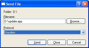
27. Click Send. The following dialog box appears:
Figure 8 The Xmodem file send for Switch dialog box
28. When the file is successfully downloaded, the following information appears:
Loading ...CCCCCCCCCCCCCCCCCCCCCCCCCCCCCCCCCCCCCCCCCCCCCCCCCCCCCCCCCCCCC
CCCCCCCCCCCCCCCCCCCCCCCCCCCCCCCCCCCCCCCCCCCCCCCCCCCCCCCCCCCCCCCCCCCCCCCC
CCCCCCCCCCCCCCCCCCCCCCCCCCCCCCCCCCCCCCCCCCCCCCCCCCCCCCCCCCCCCCCCCCCCCCCC
CCCCCCCCCCCCCCCCCCCCCCCCCCCCCCCCCCCCCCCCCCCCCCCCCCCCCCCCCCCCCC.done!
Free flash Space : 65932288 bytes
Writing flash...................................................................
........................................................................
........................................................................
........................................................................
........................................................................
........................................................................
........................................................................
.........done!
1. Set TFTP protocol parameter
2. Set FTP protocol parameter
3. Set XMODEM protocol parameter
0. Return to boot menu
Enter your choice(0-3):
29. Type 0 to return to the boot menu.
|
|
NOTE: When the system reboots, you must change the baud rate for HyperTerminal back to 9600 bps by following Step 6 and Step 7. |
Setting new main and backup system software images
After you download a new system software image to the switch, set the file as the main or backup system software image.
The switch uses the main system software image in normal cases, and uses the backup system software image when the main system software image is invalid.
Follow these steps to set the new main and backup system software images:
1. In the boot menu, type 2 to enter the system software image menu.
Flash:/
Number. Size(B) Time Name
===============================================================================
1 27451869 Jul/29/2010 17:35:17 newest.app
2(*) 31465833 Aug/18/2010 18:19:38 SWITCH000.app
3(-). 203460 Aug/17/2010 14:19:38 old.app
Free space: 6118400 bytes
The current application file is:flash:/SWITCH000.app
The backup application file is:flash:/old.app
All system software images stored in the flash memory are displayed. The file marked with an asterisk (*) is the current main system software image, and that marked with a hyphen (-) is the current backup system software image.
2. Set the new main and backup system software images.
· Set the main system software image
Type the number of the file you want to set as the main system software image when you see the following:
Please input the primary application file number to boot :1
Confirm the name of the system software image you have selected and type Y.
The primary file you selected is flash:/newest.app, are you sure? Yes or No(Y/N):Y
The following information appears:
On reboot, flash:/newest.app will become the default primary application file to boot!
The output shows that you have successfully set the selected file as the new main system software image.
· Set the backup system software image
The configuration procedure of the backup system software image is the same as that of the main system software image, except for the following output:
Please input the backup application file number :2
The file you selected is flash:/SWITCH000.app, are you sure? Yes or No(Y/N)y
On reboot, flash:/SWITCH000.app will become the backup application file to boot!
Running the main system software image
Type Y to run the main system software image immediately.
Do you want to run flash:/newest.app now?Yes or No(Y/N)?Y
Starting to get the main application file--flash:/ newest.app!..
...............................................................................
...............................................................................
The main application file is self-decompressing................................
...............................................................................
...................................................................... done!OK
System is starting...
The following might occur at the switch startup:
1. The switch starts up with the main system software image.
2. The main system software image is faulty and the switch starts up with the backup system software image.
3. Both the main and backup system software images are faulty and the switch picks a random system software image and starts up with it.
4. If the switch still cannot start up with the random system software image, it decides that there is no valid system software image and stops picking any system software image.
Handling upgrade failures
If an upgrade failure occurs, the switch operates using the original version.
To handle upgrade failure:
1. Examine the connections of the physical ports. Reconnect ports that are not properly connected and download the system software images again.
2. Examine the HyperTerminal output for errors and typos. Correct errors and typos and download the system software image again. The errors can be:
? You have selected a baud rate of another value rather than 9600 bps to download the .app file from the boot menu, but did not set to the corresponding baud rate on HyperTerminal.
? You typed an incorrect IP address of the TFTP server or switch, filename, or TFTP work directory.
? You typed an incorrect IP address of the FTP server or switch, filename, FTP username, password, or FTP work directory.
3. Verify that FTP or TFTP server software is running and has correct settings.
4. Verify that the flash has enough memory to store the downloaded files.
5. Verify that system software and Boot ROM are compatible. For the compatibility between the system software and the Boot ROM, see the hardware and software compatibility matrix in Release Notes.
6. Verify that the Boot ROM image is applicable to the target cards.
Copyright ©2010-2012 Hangzhou H3C Technologies Co., Ltd.
