
- Released At: 24-02-2023
- Page Views:
- Downloads:
- Table of Contents
- Related Documents
-
AD-Campus 6.2 Operations Monitoring
Deployment Guide
Document version: 5W100-20230221
Copyright © 2023 New H3C Technologies Co., Ltd. All rights reserved.
No part of this manual may be reproduced or transmitted in any form or by any means without prior written consent of New H3C Technologies Co., Ltd.
Except for the trademarks of New H3C Technologies Co., Ltd., any trademarks that may be mentioned in this document are the property of their respective owners.
The information in this document is subject to change without notice.
Contents
Unified Platform as the network operations monitoring platform
Configure the physical devices for operations monitoring
Configure Unified Platform for network operations monitoring
Example: Send alarm notifications via SMS
Example: Send alarm notifications via email
Example: Send alarms notifications via WeChat
Example: Send alarm notifications via WeCom
Filter, clear, or acknowledge alarms
View global resource monitoring information
Example: Upgrade system logs to alarm notifications
Use an external platform for network operations monitoring
Obtain alarms reference documents
Obtain alarm or log messages reference
Obtain trap definitions from Unified Platform
Appendix A Alarm and trap management on Unified Platform
Manage alarms on Unified Platform
Obtain trap definitions from Unified Platform
Commonly used filtering criteria
Overview
With the AD-Campus 6.2 solution, you can use one of the following methods to monitor network operations:
· Use Unified Platform to monitor network operations.
· Use an external network operations monitoring platform. This platform receives Syslog and SNMP notifications from the controller or network devices.
The procedure to configure network operations monitoring differs depending on the method you use.
Unified Platform as the network operations monitoring platform
Prompt notification of network issues enables administrators to take quick action on the issues before they deteriorate or interrupt services. Unified Platform supports notifications of alarms via SMS, email, WeChat, and WeCom. The configuration procedure differs by notification method.
Prerequisites
The alarm feature depends on the kernel-base application package. Before you configure Unified Platform to monitor network operations, make sure you have installed the kernel-base application package and its license.
To place a device in maintenance state, make sure you have installed the suspension application package on Unified Platform.
The application packages are licensed-based. For more information about the licenses, see the configuration guides provided by the production department.
Configure the physical devices for operations monitoring
The physical devices (primarily switches and security appliances) use SNMP to push events to the operations monitoring platform. The monitoring platform can also polls the MIBs on the devices to generate alarms.
The following information describes the SNMP configuration procedure on the network devices. If underlay automation is used, some of the SNMP settings are automatically deployed on the incorporated devices and you do not need to configure them.
1. Enable the information center and the SNMP agent.
[device] info-center enable
[device] snmp-agent
2. Configure a read-only community string and a read and write community string. Then, enable SNMP versions. This example enables all SNMP versions.
[device] snmp-agent community read public
[device] snmp-agent community write private
[device] snmp-agent sys-info version all
3. Enable SNMP notifications and enable SNMP notifications for service modules, for example, BGP.
[device] snmp-agent Trap enable
[device] snmp-agent Trap enable bgp
4. Specify Unified Platform as a target host to receive SNMP notifications at the northbound service VIP of its cluster. Optionally, configure authentication for security purposes.
¡ Spine/leaf devices:
[device] snmp-agent target-host Trap address udp-domain 100.1.0.100 vpn-instance vpn-default params securityname public v2c
¡ Access devices:
[device] snmp-agent target-host Trap address udp-domain 100.1.0.100 params securityname public v2c
5. Specify Unified Platform as a log host to receive logs at the northbound service VIP of the Matrix cluster.
¡ Spine/leaf devices:
[device] info-center loghost vpn-instance vpn-default 100.1.0.100
¡ Access devices:
[device] info-center loghost 100.1.0.100
Configure Unified Platform for network operations monitoring
Deploy DNS services
If external connectivity is deployed for the data center network, you must deploy a DNS server. The server uses a distributed database to translate domain names to IP addresses. The DNS server listens for requests on UDP port 53.
To deploy a DNS server on Unified Platform:
1. Open a Web browser and enter https://Matrix_ip_address:8443/matrix/ui in the address bar to log in to Matrix. The Matrix_ip_address argument represents the northbound service VIP of the Matrix cluster.
2. Navigate to the Deploy > Clusters page, and then click the Cluster Parameters tab.
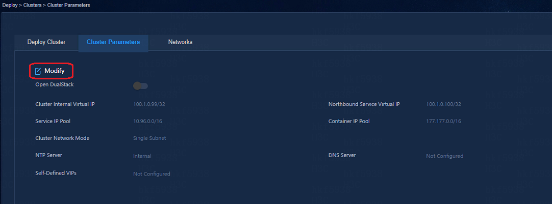
3. Click the Edit icon ![]() to edit the
cluster parameters.
to edit the
cluster parameters.
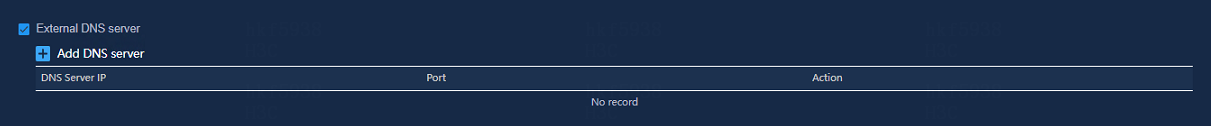
4. Select External DNS server,
and then click the ![]() icon next to the Add DNS server field.
icon next to the Add DNS server field.
5. In the dialog box that opens, enter a DNS server IP address and a service port number, and then click Apply, as shown in Figure 3.
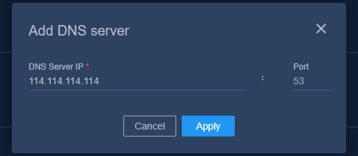
6. Click Apply to deploy the DNS server.
Example: Send alarm notifications via SMS
This example uses the Emay SMS platform to deliver SMS alarm notifications.
Prerequisites
· Make sure you have license information (serial number and encryption key) for registration with the Emay SMS platform.
· Make sure SeerEngine-Campus has incorporated the monitored network devices and can receive SNMP notifications from them.
· Make sure a DNS server address has been specified on Unified Platform and Unified Platform has Internet connectivity.
Configure the SMS center
1. Open a Web browser, and then enter http://ip_address:30000/central in the address bar to log in to Unified Platform. The ip_address argument represents the northbound service VIP of the Matrix cluster.
2. Navigate to the System > System Settings > SMSC Settings page.
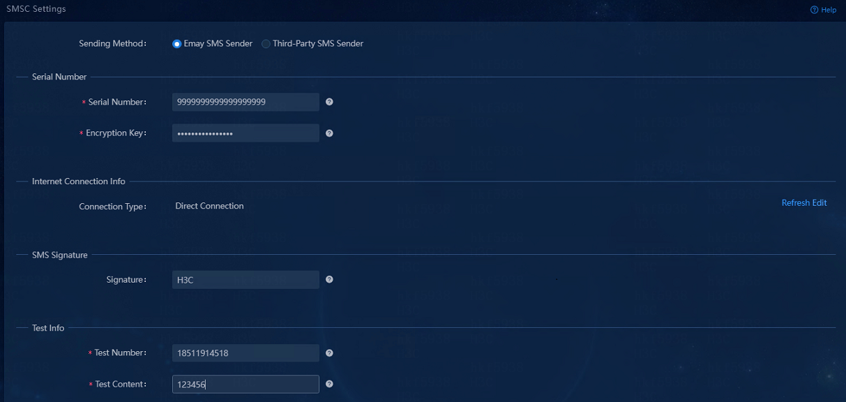
3. Select the Emay SMS Sender option for the Sending Method field.
4. Enter the serial number and encryption key for registration with the Emay platform.
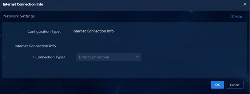
5. In the Internet Connection Info area, click Edit.
6. In the dialog box that opens, select a connection type, and then click OK.
In this example, select Direct Connection.
Figure 5 Configuring the Internet connection
7. On the SMSC Settings page, click Refresh. Verify that the Internet connection information has been set successfully.
8. In the SMS Signature area, enter a signature template.
9. In the Test Info area, enter a test number and the test content.
10. Click Test to send the test content to the test number. Make sure the SMS message can be sent successfully.
Figure 6 Sending the test SMS message

Configure alarm forwarding via SMS messages
1. Log in to Unified Platform.
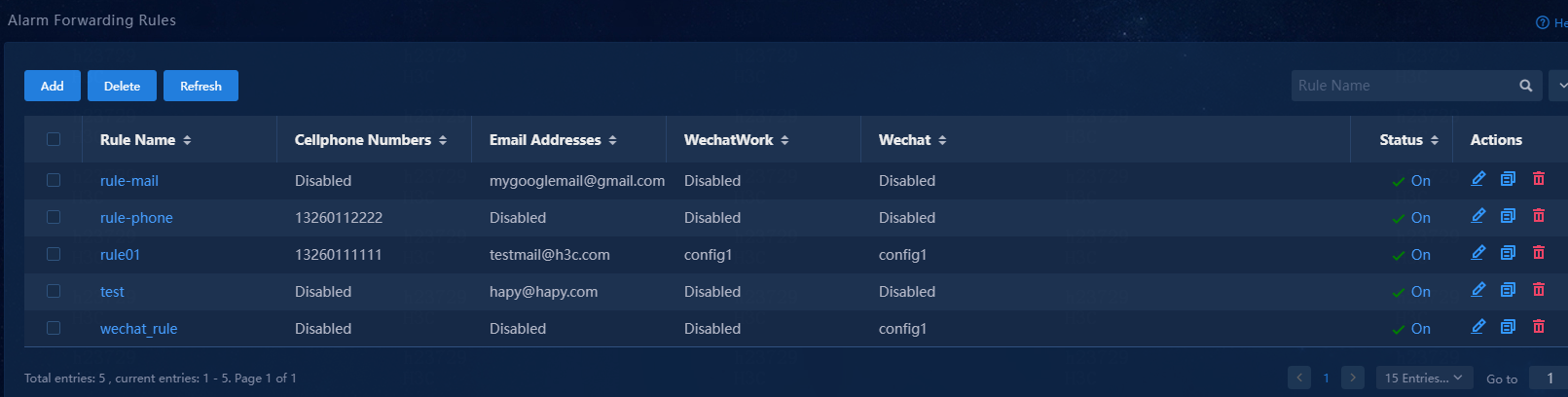
2. Navigate to the Monitor> Alarm > Alarm Forwarding Rules page.
Figure 7 Alarm forwarding rules
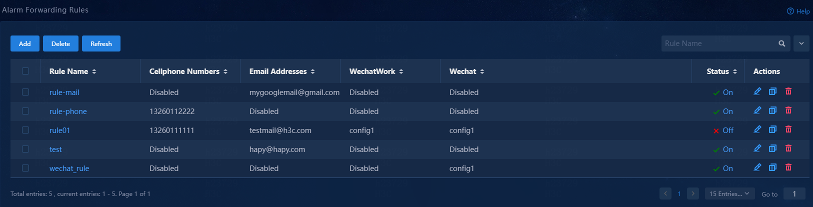
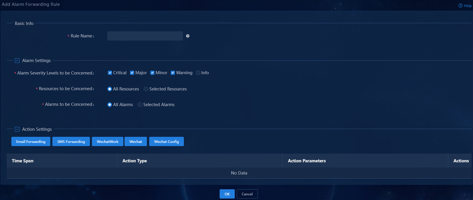
3. Click Add to add an alarm forwarding rule.
Figure 8 Adding an alarm forwarding rule
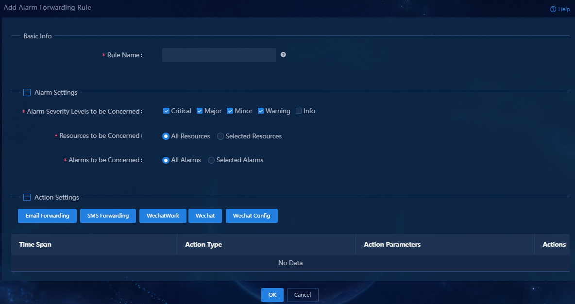
4. Configure the alarm forwarding rule:
¡ Rule Name: Assign a name to the rule.
¡ Alarm Severity Levels to be Concerned: Select the severity levels of alarms to be sent via SMS. The system sends alarms via SMS only for the selected severity levels.
¡ Resources to be Concerned: Select resources of interest. The system sends alarms via SMS only for resources of interest. By default, the All Resources option is selected.
¡ Alarm to be Concerned: Select alarms of interest. The system sends only alarms of interest via SMS. This example selects the All Alarms option.
5. Click SMS Forwarding.
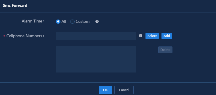
6. Specify the period of time during which alarms are generated, enter a phone number, and then click Add. By default, the All option is selected for the Alarm Time field.
Figure 10 Adding mobile phone numbers
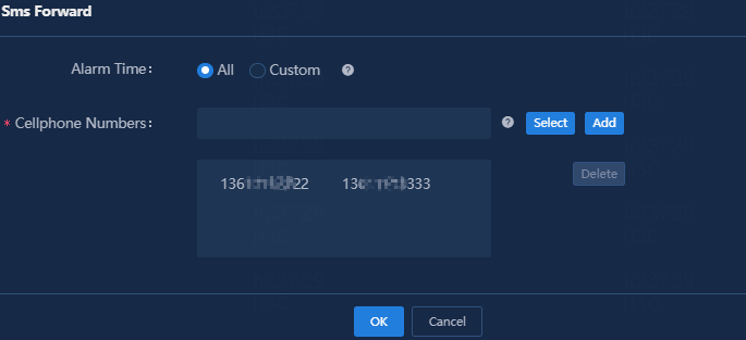
7. Click OK.
In the Action Settings area, verify that the SMS alarm forwarding rule has been added.
Figure 11 Adding an SMS alarm forwarding rule
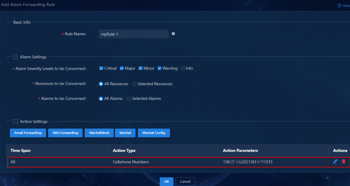
8. Click OK.
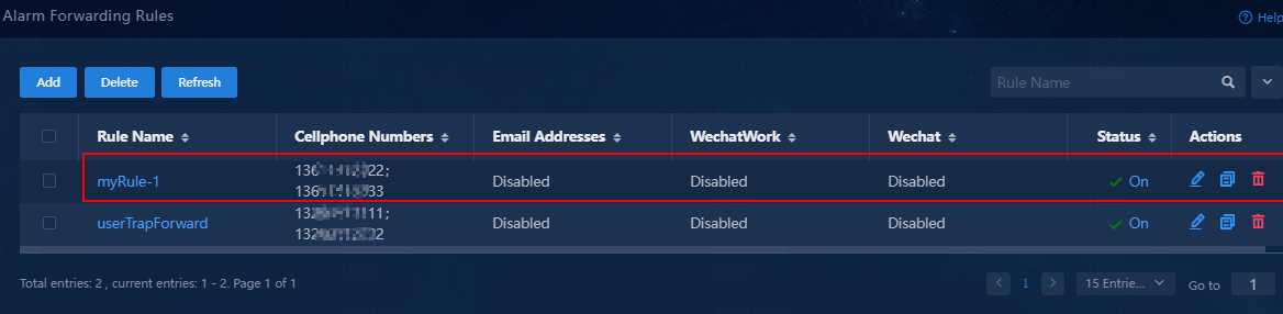
Verify that the SMS alarm forwarding rule has been added to the rule list, and the rule is in enabled (On) state.
Figure 12 SMS alarm forwarding rule list
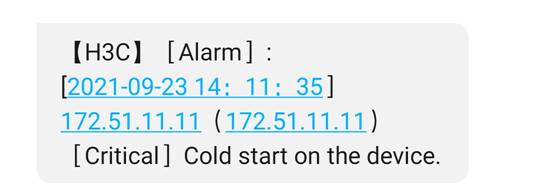
9. When an alarm occurs, the specified mobile phones will receive a notification of the alarm.
Figure 13 Alarm SMS message
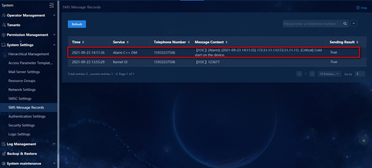
10. Navigate to the System > System Settings > SMS Message Records page to view the SMS messages that have been sent.
Figure 14 SMS message records
Example: Send alarm notifications via email
Configure Unified Platform to promptly notify remote maintenance staff of alarms via email.
Prerequisites
· Only a user with administrator permissions can configure the mail server and alarm forwarding rules.
· Make sure the mail server has been set up successfully and can access the mail sending ports, such as POP and SMTP.
· Make sure the mail client can send and receive mails through the mail server.
Summary procedure
1. Add a mail account on the mail server.
2. Configure the mail server information.
3. Configure alarm forwarding rules.
4. Verify the configuration.
Configure the mail server information
To send mail notifications, you must first specify a mail server.
1. Log in to Unified Platform, and then navigate to the System > System Settings > Mail Server Settings page.
Figure 15 Mail server settings
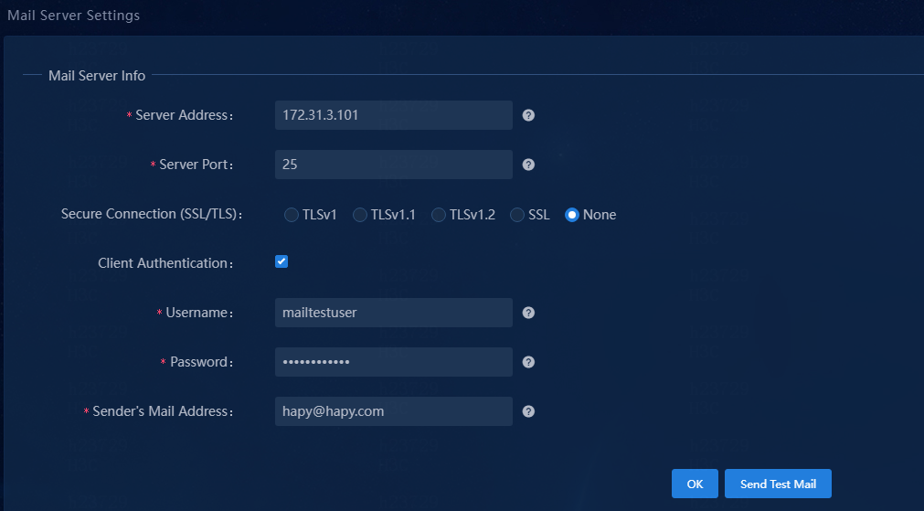
2. Configure the mail server settings:
¡ Server Address: Enter the domain name or IP address of the mail server. In this example, use the address of the mail server set up on the internal network.
¡ Server Port: Enter the port number of the mail server. The default is 25.
¡ Secure Connection (SSL/TLS): Select TLSv1, TLSv1.1, TLSv1.2, or SSL for secure connection to the server. If a secure connection is not required, select None.
¡ Client Authentication: Specify the same client authentication settings as those on the server. If client authentication is enabled on the mail server, you must also enable client authentication for the mail server in the system, and enter the sender's username and password. If the mail server does not require client authentication, do not configure client authentication.
¡ Sender’s Mail Address: Enter the mail address of the sender. In this example, enter [email protected].
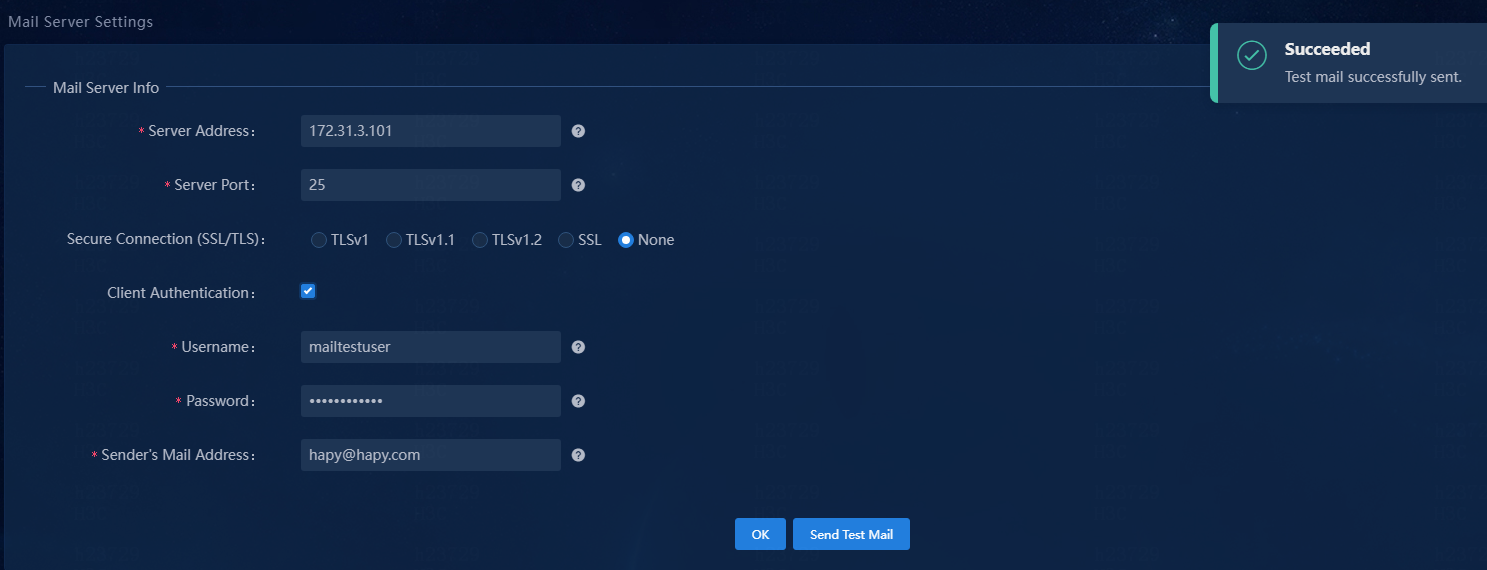
3. Click Send Test Mail to test server connectivity and correctness of the username and password.
|
|
NOTE: If the mail server cannot be pinged, the system makes continuous attempts to send the test mail until the mail is sent successfully or the maximum number of attempts is reached. |
Figure 16 Successful mail test
4. Click OK.
Add an alarm forwarding rule
1. Navigate to Monitor > Alarm > Alarm Forwarding Rules.
2. Click Add.
Figure 17 Adding an alarm forwarding rule
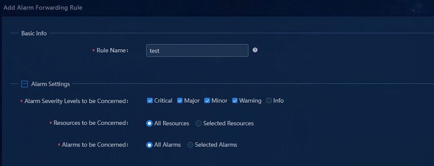
3. Configure the alarm forwarding rule:
¡ Rule Name: Assign a name to the mail alarm forwarding rule. In this example, enter test.
¡ Alarm Severity Levels to be Concerned: Select one or multiple alarm severity levels of interest. Use the default settings in this example.
¡ Resources to be Concerned:
- To forward alarms generated by any resources, select the All Resources option.
- To forward alarms generated by only resources of interest, select the Selected Resources option, and then select resources or resource groups of interest. If you select a group, all resources in that group are selected.
¡ Alarms to be Concerned:
- To forward all alarms, select the All Alarms option.
- To forward only a subset of alarms, select the Selected Alarms option, and then click Select. In the dialog box that opens, select alarms of interest.
Figure 18 Configuring alarm forwarding via email
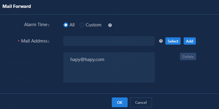
4. In the Action Settings area, click Email Forwarding.
5. Configure the alarm forwarding rule:
¡ Alarm Time: Specify the period of time during which alarms are generated. Select the All or Custom option.
- All: The system forwards alarms regardless of when they are generated.
- Custom: The system forwards only alarms generated within the selected time span. For example, if you set the time span to 00:00-23:59 for a day, the system forwards all alarms generated on this day.
This example uses the default setting.
¡ Mail Address: Specify the mail addresses for receiving alarm notification mails. You can specify one or multiple unique mail addresses. The mail address format is login_username@host_name.domain_name. In this example, enter [email protected].
6. Click OK to add the alarm forwarding rule.
Figure 19 Email alarm forwarding rule added successfully
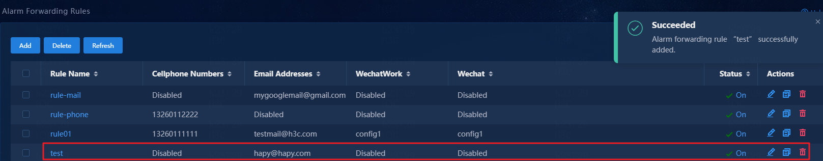
|
|
NOTE: If an alarm matches multiple alarm forwarding rules, the alarm is forwarded based on each matching rule. If the matching rules contain the same destination (for example, the same mail address, mobile phone number, or message template), the system sends only one notification of the alarm to that destination. |
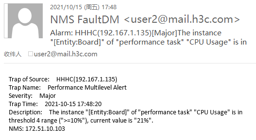
Verify the configuration
Access the mail box for receiving alarm notifications to verify that it can receive alarm notifications of interest pushed by Unified Platform.
After receiving an alarm notification, you can log in to Unified Platform to process the alarm.
Figure 20 Receiving an alarm notification
Example: Send alarms notifications via WeChat
This example uses a subscription account that has passed WeChat authentication to introduce the configuration procedures.
Restrictions and guidelines
· To apply for a WeChat official account, go to the WeChat official accounts platform. For more information, access https://mp.weixin.qq.com/.
· The system does not support WeChat-based authentication for private subscription accounts. Do not select the private application entity type when you apply for a subscription account.
Prerequisites
· SeerEngine-Campus has incorporated the monitored network devices and Unified Platform can receive SNMP notifications from them.
· A DNS server address has been specified on Unified Platform.
· The real addresses of the Unified Platform servers can communicate with the WeChat platform.
Configure a WeChat subscription account
1. Open a Web browser, and then enter https://mp.weixin.qq.com/ in the address bar to access the WeChat official accounts platform.
Figure 21 Homepage of the WeChat official account platform
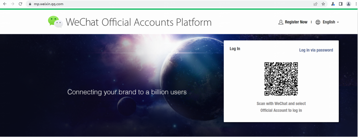
2. Scan the QR code with WeChat or click Log in via password to log in the platform. The official account page opens after you log in successfully.
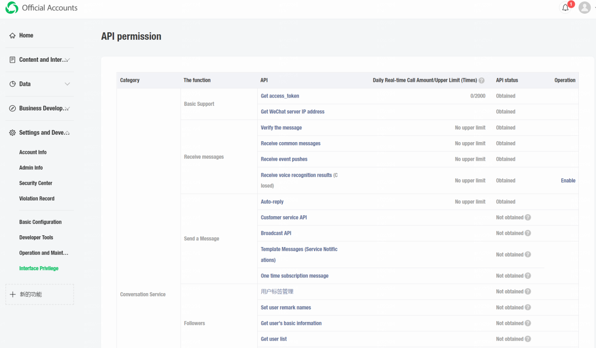
3. From the left navigation pane, select Settings and Development > Interface Privilege.
4. On the page that opens, verify that access to the APIs required for alarm forwarding via WeChat has been granted.
You must obtain access to the following APIs:
¡ Get access_token
¡ Customer service API
¡ Get user list
¡ Get user's basic information
You can also obtain access to any other
APIs as needed. If access to an API is not obtained, click the Help icon ![]() next to the Not obtained
value in the API status column to view information about obtaining access rights to APIs.
next to the Not obtained
value in the API status column to view information about obtaining access rights to APIs.
5. From the left navigation pane, select Settings and Development > Basic Configuration.
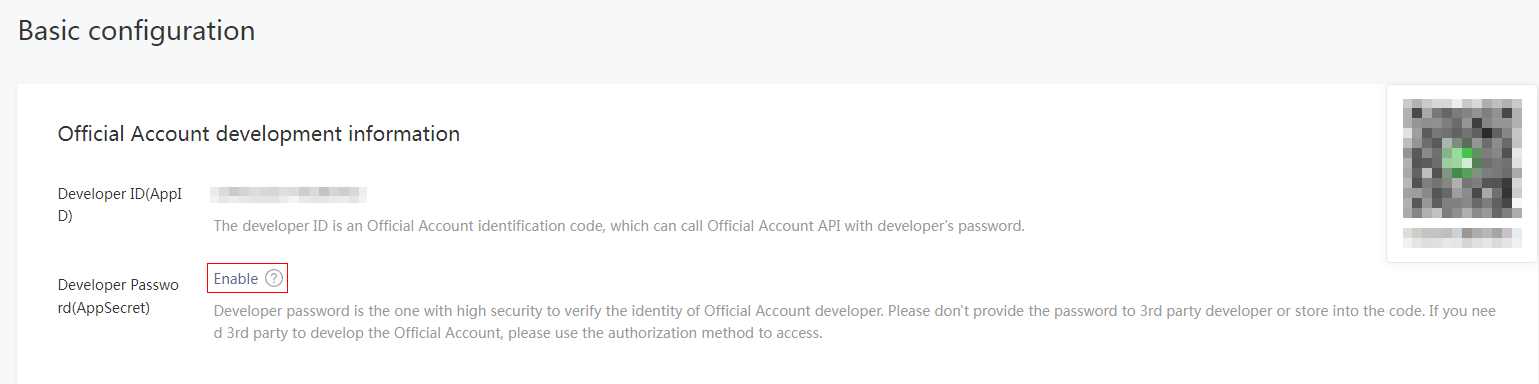
6. Click the Enable link next to the Developer Password(AppSecret) option in the Official Account development information area.
Figure 24 Setting a developer password
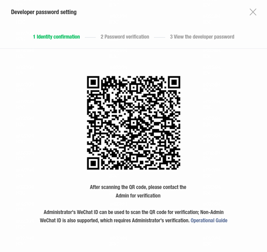
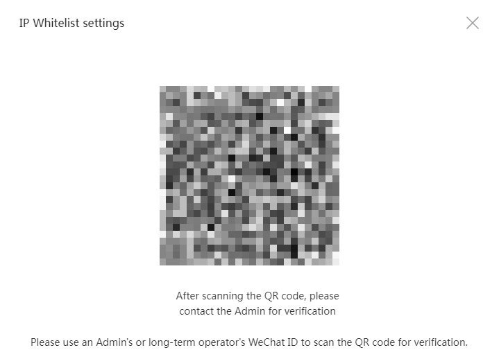
7. Use WeChat to scan the QR code for authentication. The page for setting the developer password opens after authentication succeeds.
Figure 25 Password verification
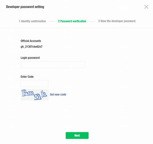
8. Enter the official account password and the verification code. Then, click Next.
9. On the page that opens, review the following developer information:
¡ AppID: The developer ID uniquely identifies the official account developer. You must provide this ID and the developer password (AppSecret) in pairs to call the APIs for the official account. Unified Platform uses the AppID and AppSecret to communicate with the WeChat server.
¡ AppSecret: The password provided to authenticate the developer's identity for security.
|
|
IMPORTANT: After this page closes, the WeChat official account platform does not store or display the AppSecret. As a best practice, copy and save the AppSecret and AppID to a document for future use. |
Figure 26 Viewing the developer password
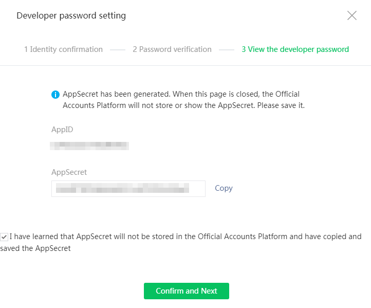
10. After you copy and save the AppSecret and AppID, select I have learned that AppSecret will not be stored in the Official Accounts Platform and have copied and saved the AppSecret, and then click Confirm and Next to enter the page showing that the developer setting has been completed.
Figure 27 Developer setting completed
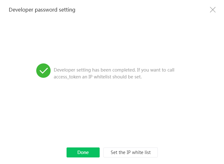
11. If all information is correct, click Done. Then, the system returns to the basic configuration page. If you forget your AppSecret, click the Reset link next to the Developer Password(AppSecret) option in the Official Account development information area to reset the AppSecret.
Figure 28 Resetting the AppSecret of a developer
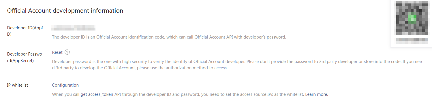
12. Click the Configuration link next to the IP whitelist field in the Official Account development information area. On the page that opens, add trusted IP addresses to the IP whitelist.
When you obtain the access_token API through the developer ID, you must add the source IP to the whitelist. For the purpose of this example, add the northbound service VIP of the Matrix cluster to the whitelist. This IP address is publicly accessible to the Internet. To specify multiple IP addresses, press Enter after inputting an IP address.
Figure 29 Adding IP addresses to the IP whitelist
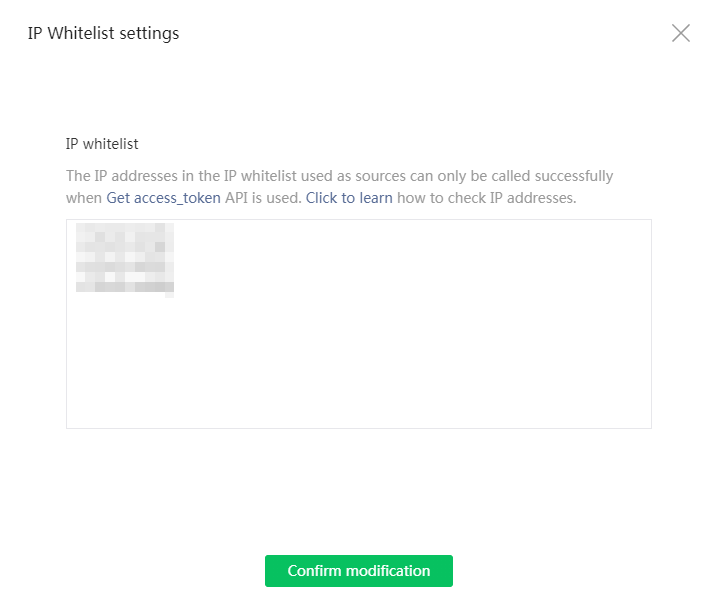
13. Click Confirm modification. The authentication page opens.
14. If identity authentication succeeds, a page opens displaying the IP addresses added to the whitelist.
Figure 31 Viewing the IP whitelist
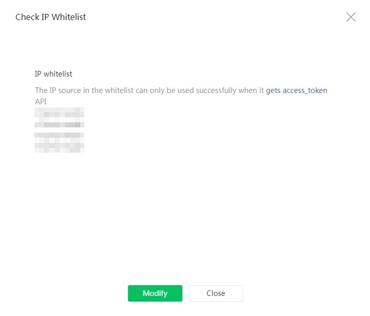
15. Click Close.
16. To edit the IP whitelist, click the View link next to the IP whitelist field.
Add the WeChat official account to Unified Platform
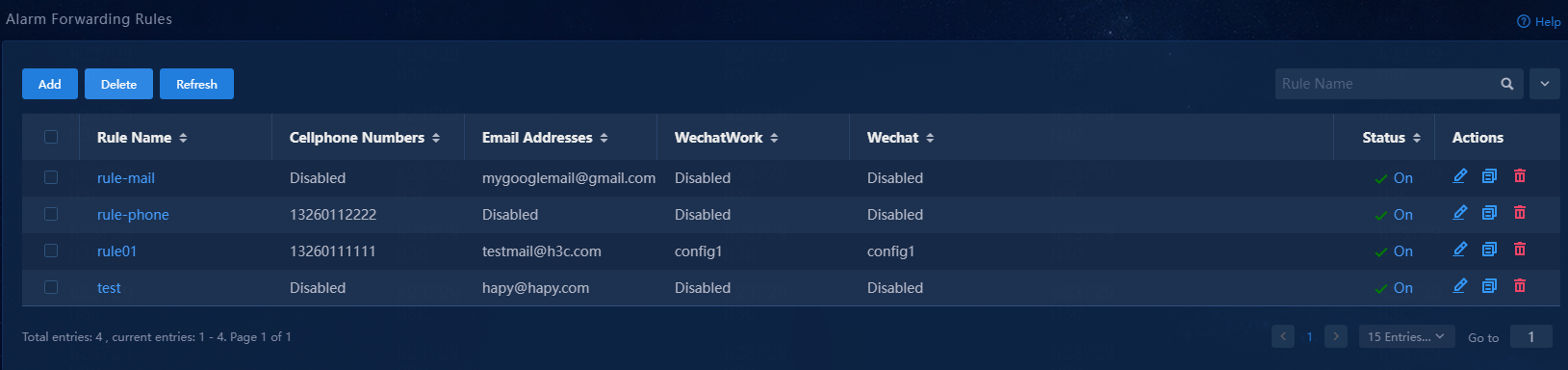
1. Log in to Unified Platform, and then navigate to the Monitor > Alarm > Alarm Forwarding Rules page.
Figure 32 Alarm forwarding rules
2. Click Add. The page for adding an alarm forwarding rule opens.
Figure 33 Adding an alarm forwarding rule

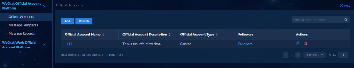
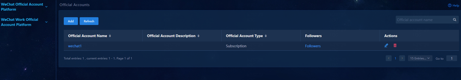
3. Click Wechat Config in the Action Settings area. From the left navigation pane, select WeChat Official Account Platform > Official Accounts.
Figure 34 WeChat official account platform-Official accounts
5. Configure the official account parameters:
¡ Official Account Name: Enter a self-defined official account name.
¡ Official Account Description: Enter a description for the official account.
¡ Official Account Type: Select an official account type. Options include Subscription and Service. This example selects Subscription.
¡ Token: Information used by Unified Platform to identify the WeChat official account platform as the source of a message. You can define the token as needed, except that it must be an alphanumeric string of 3 to 32 characters and start with a letter. In this example, the token is qwer123456.
¡ AppID and AppSecret: Enter the AppID and AppSecret you obtained previously.
Figure 35 Adding an official account
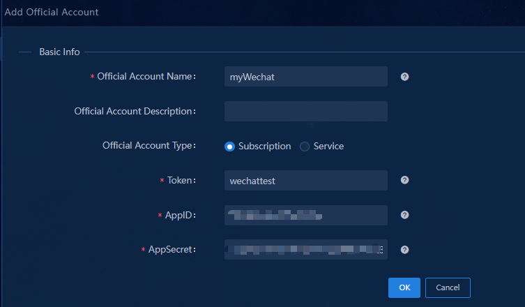
Figure 36 Official account details
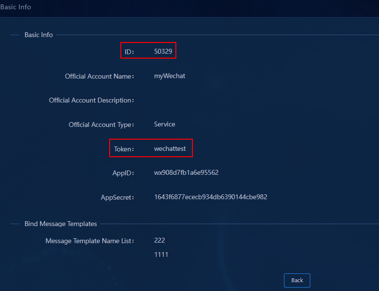
7. Record the ID and token displayed on this page for future use.
8. Click Back to return to the official account page. Click the follower link in the Followers column for an official account. The follower list page opens.
Figure 37 Viewing the follower list
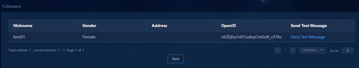
9. Click the link in the Send Test Message column for a follower to open the Send Test Message page.
Figure 38 Sending a test message
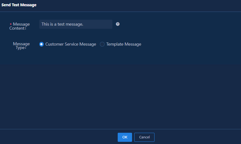
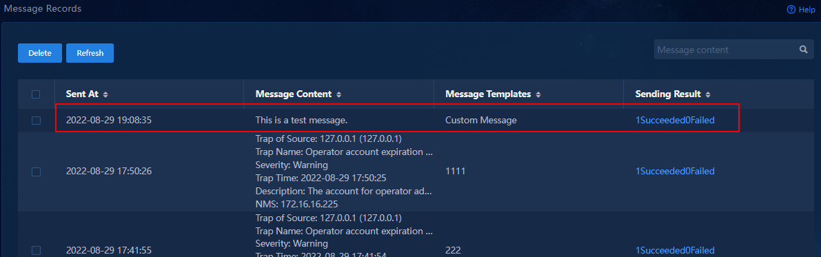
10. In the Message Content field, enter a test message, and click OK to send the test message to the follower. To view the status of the test message, select WeChat Official Account Platform > Message Records.
Figure 39 Message records
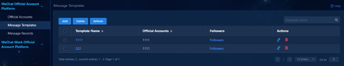
11. Navigate to the WeChat Official Account Platform > Message Templates page. A message template specifies the official account for alarms and the target followers.
Figure 40 Message templates
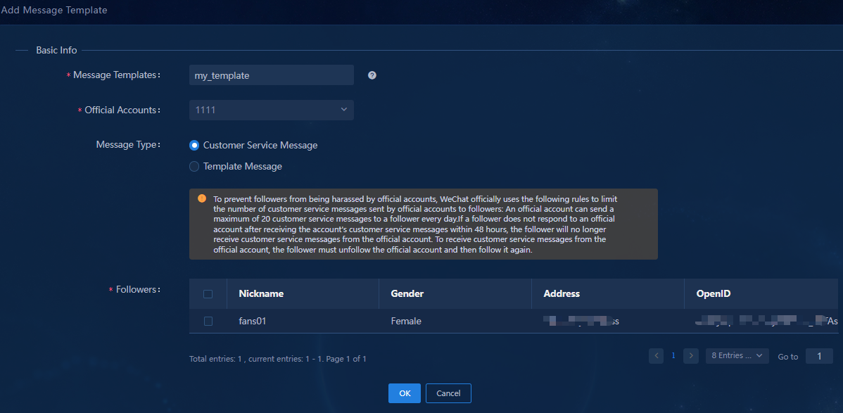
12. Click Add.
13. Configure the message template parameters:
¡ Message Templates: Enter a message template name, a string of 1 to 32 characters.
¡ Official Accounts: Select official accounts to receive alarm notifications from Unified Platform.
¡ Followers: Select the followers to whom the alarm notifications will push.
Figure 41 Adding a message template
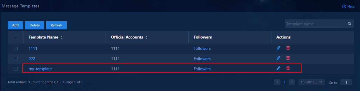
14. Click OK.
15. On the Message Templates page that opens, verify that the message template has been added.
Figure 42 Newly added message template
|
|
NOTE: · When you delete an account, Unified Platform automatically deletes its followers. · You cannot delete an official account that has been bound to a message template. To identify the name of the bound message template, view the official account details. · The system determines that the test message has failed to be sent to the selected follower if that follower does not interact with its subscription account within 24 hours after subscription. This issue is removed after the follower sends a message to the official account. · If a follower specified in the message template has unfollowed the official account, Unified Platform removes that follower from the message template automatically. |
Configure the WeChat official account server
1. Log in to the WeChat official accounts platform.
2. From the left navigation pane, select Settings and Development > Basic Configuration.
3. In the server configuration (disabled) area, click Change Configuration. The Fill in server configuration page opens.
4. Configure the server:
¡ URL: Enter the URL in the format of http://Unified Platform’s northbound service VIP:port/Wechat/weChat/WechatServlet/ID or http://domain name/Wechat/weChat/WechatServlet/ID. In the URL, replace the ID argument with the ID you have obtained when you added the account, and replace the port argument with the service port number.
¡ Token: Enter the token value you have specified on Unified Platform for the official account.
¡ EncodingAESKey: Enter the encryption and decryption key for the message body. You can manually enter one or randomly generate one.
¡ Message Encryption Method: Select a method as needed. This example selects Plaintext Mode.
Figure 43 Specifying the server configuration
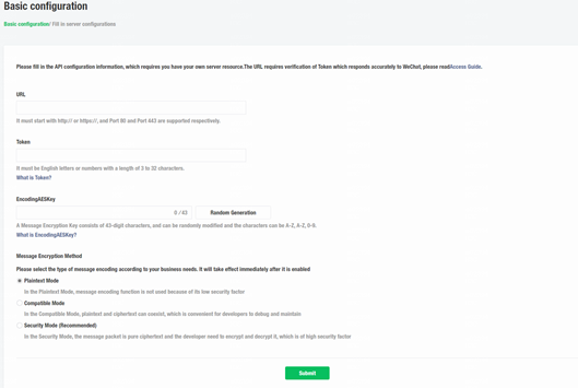
5. Click Submit.
6. In the dialog box that opens, click Confirm.
The system returns to the basic configuration page.
7. On the basic configuration page, click Enable to enable the server configuration.
Configure alarm forwarding rules
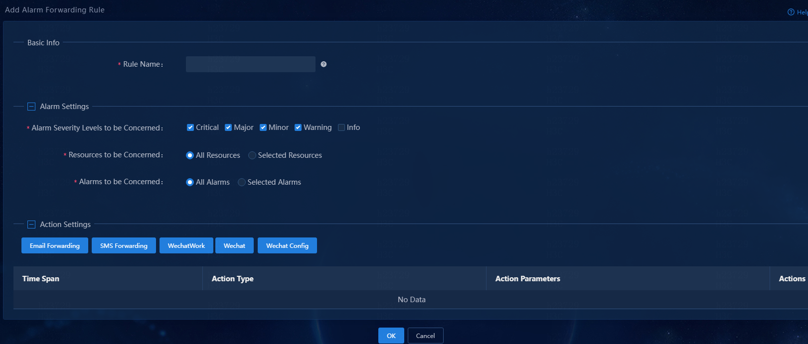
1. Log in to Unified Platform, navigate to the Monitor > Alarm > Alarm Forwarding Rules page, and then click Add to add an alarm forwarding rule.
2. Configure an alarm forwarding rule:
¡ Rule Name: Enter an alarm forwarding rule name, a string of 1 to 32 characters.
¡ Alarm Severity Levels to be Concerned: Select alarm severity levels of interest. The system sends alarm notifications only for the specified severity levels. Available options are Critical, Major, Minor, Warning, and Info.
¡ Resources to be Concerned: Select resources of interest. Available options are All Resources and Selected Resources. By default, the All Resources option is selected. Unified Platform sends notifications of alarms generated by all resources. To send notifications of alarms generated by only some of the resources, select the Selected Resources option, and then select resource groups or resources of interest. This example uses the All Resources option.
¡ Alarms to be Concerned: Select alarms of interest. Available options are All Alarms and Selected Alarms. By default, the All Alarms option is selected. Unified Platform sends notifications of all alarms. To send notifications of only some of the alarms, select the Selected Alarms option, and then select traps. You can also configure parameters for traps. If you configure parameters for selected traps, Unified Platform sends notifications of only alarms that match the configured parameters. This example uses the All Alarms option.
|
|
NOTE: Traps are one form of SNMP notifications. This document uses traps and SNMP notifications interchangeably. |
Figure 44 Adding an alarm forwarding rule
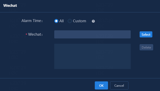
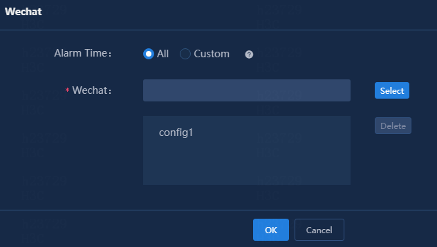
3. Click Wechat Config in the Action Settings area.
4. Specify the period of time during which alarms are generated. Select the All or Custom option.
¡ All: The system forwards alarms regardless of when they are generated.
¡ Custom: The system forwards only alarms generated within the selected time span.
This example selects the All option.
Figure 45 WeChat forwarding
5. Click Select. On the page that opens, select a WeChat forwarding message template.
Figure 46 Selecting a WeChat forwarding message template
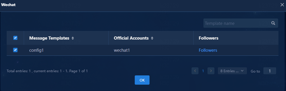
6. Click OK.
The system returns to the WeChat forwarding page.
7. On the WeChat forwarding page, verify that the selected message template has been added.
Figure 47 Message template added successfully
8. Click OK.
The system returns to the page for adding the alarm forwarding rule.
9. In the Action Settings area, view the newly added WeChat forwarding action and edit or delete it as needed.
Figure 48 Adding an alarm forwarding rule
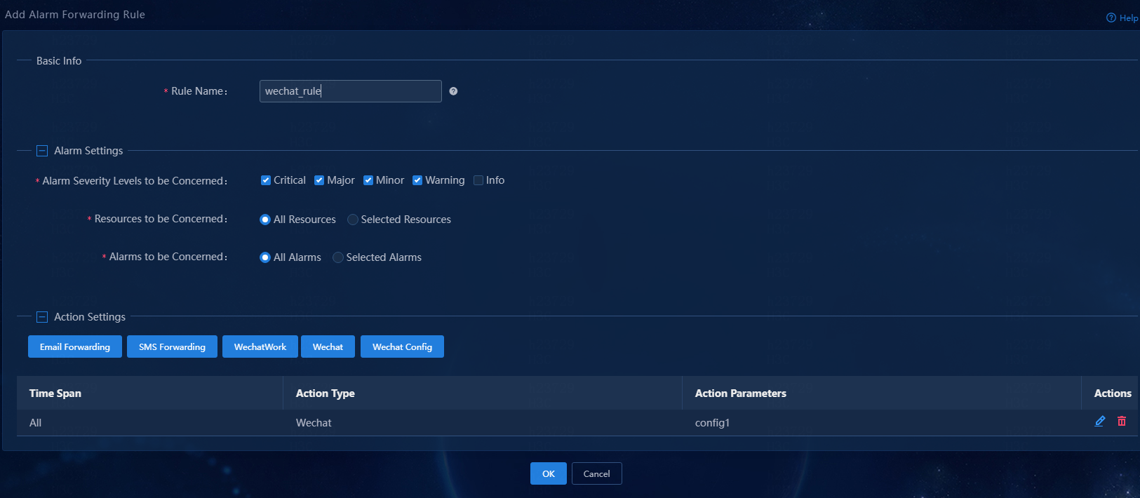
10. Click OK.
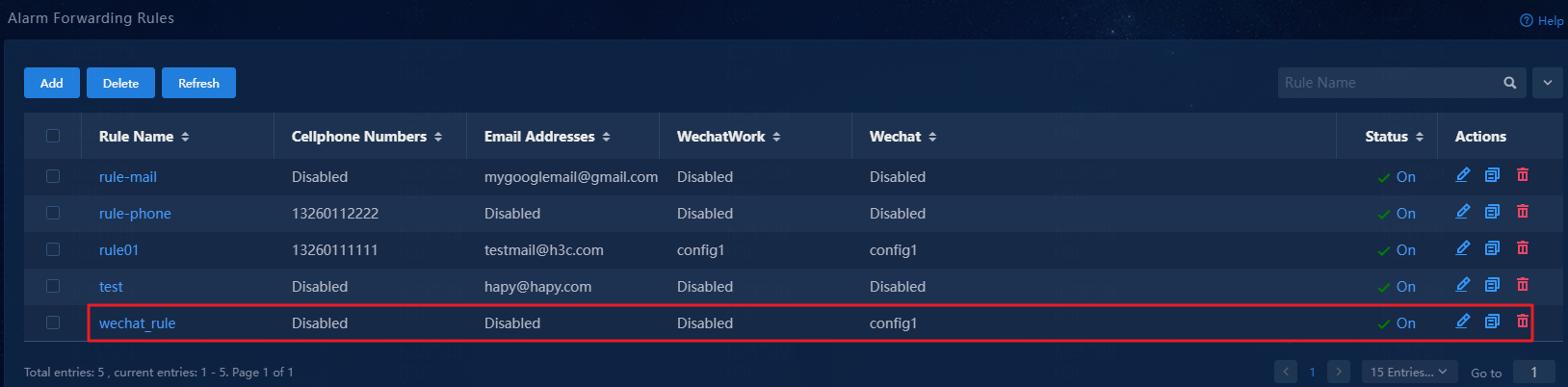
The system returns to the Alarm Forwarding Rules page.
11. Verify that the alarm forwarding rule has been added. Then, you can enable, edit, or delete it as needed.
Figure 49 Alarm forwarding results
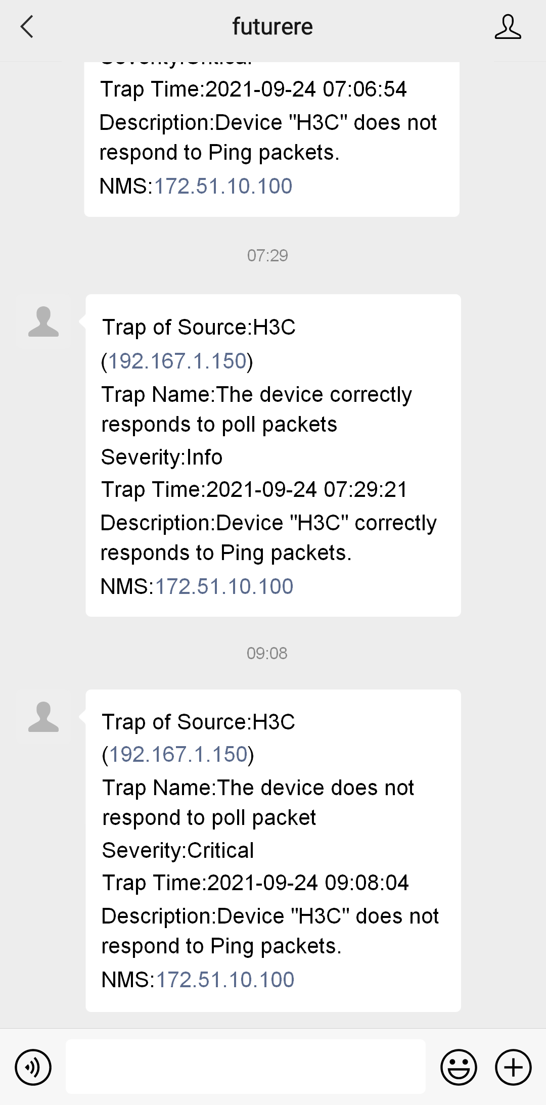
Verify the configuration
Verify that you can receive alarms that match the configured conditions from Unified Platform in the WeChat official account on your mobile phone.
Verify that you can log in to Unified Platform to process the alarms.
Figure 50 Receiving forwarded alarms in WeChat
Example: Send alarm notifications via WeCom
Register a WeCom account
1. Access https://work.weixin.qq.com.
Figure 51 Registering a WeCom account
2. Click Sign Up to register a WeCom account.
Figure 52 Entering WeCom account registration information

3. Enter the company and administrator information, and then scan the QR code with the administrator's WeChat account to bind the WeCom account to the administrator's WeChat account.
Figure 53 Entering WeCom account registration information
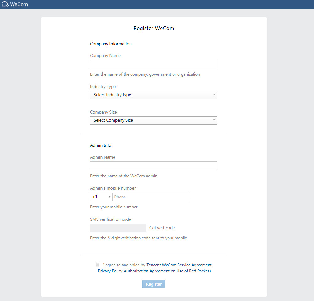
4. Select I agree to and abide by Tencent WeCom Service Agreement Privacy Policy Authorization Agreement on Use of Red Packets, and then click Register.
Create an app
1. Log in to WeCom with the registered account. On the top navigation bar, click App Management.
Figure 54 App management
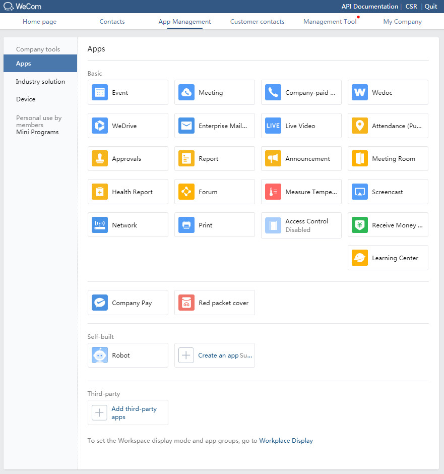
2. Click the Create an app
![]() icon to enter the Create an app page.
icon to enter the Create an app page.
Figure 55 Creating an app
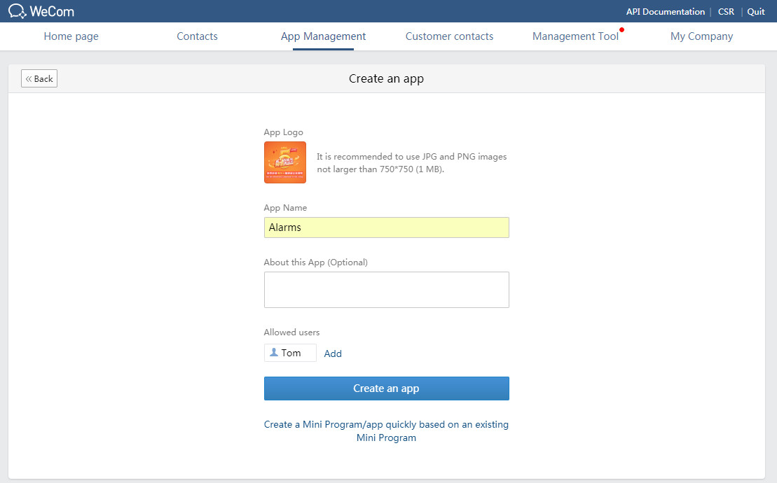
3. Configure the app information, or use an existing mini program to add an app. This example configures the app as follows:
¡ App Logo: Click the logo icon, and click Select image to select an image as the app logo. Click Save to save the configuration.
¡ App Name: Enter an app name. In this example, enter Alarms.
¡ About this App (Optional): Enter information about the app to help users learn about its functionality. This example uses the app to receive system alarm notifications.
¡ Allowed users: Select departments or members that can access this app.
4. Click Create an app.
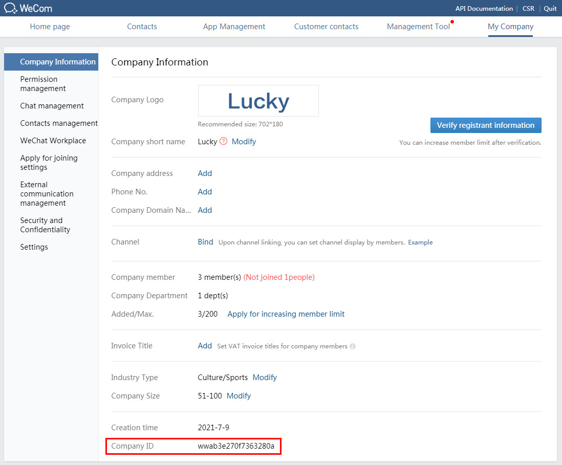
View information about the WeCom account
Before you configure Unified Platform to send alarm notifications via WeCom, you must first obtain the company ID and application secret of the WeCom account.
1. On the top navigation bar, click My Company. On the page that opens, identify the company ID.
Figure 56 Identifying the company ID
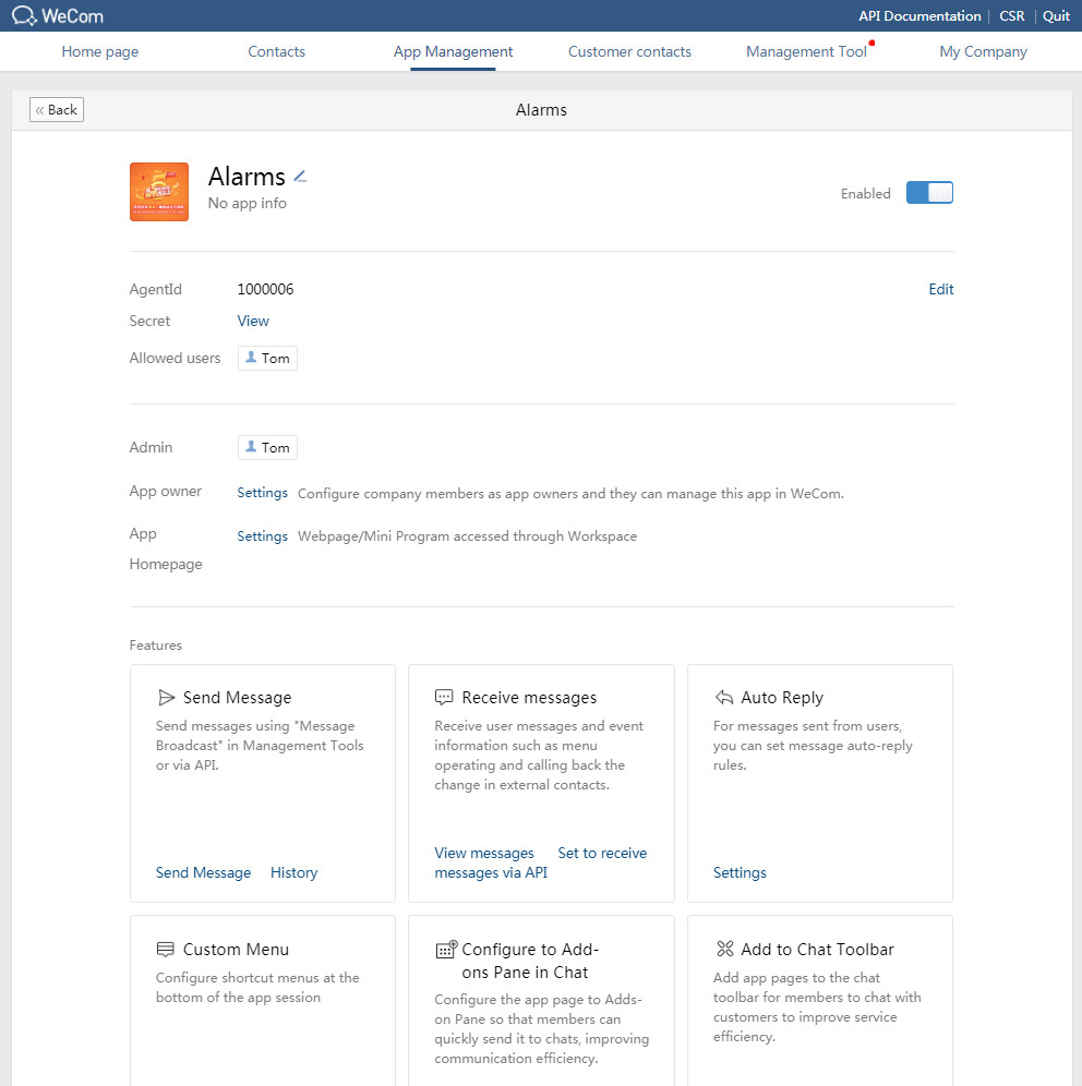
2. On the top navigation bar, click App Management. Click the newly added app to view detailed information about the app.
Figure 57 Viewing app information
3. Click the View link next to the Secret field.
Figure 58 Viewing secret information
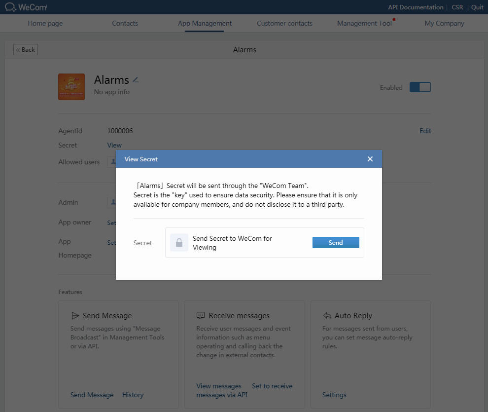
4. Click Send to send the secret to the administrator's WeCom account.
Figure 59 Viewing the secret information as the administrator
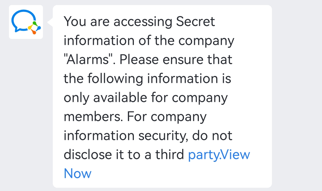
5. Click the View Now link to view the secret.
Configure the WeCom account in Unified Platform
Add the WeCom account
1. Log in to Unified Platform, and then navigate to the Monitor > Alarm > Alarm Forwarding Rules page. The alarm forwarding rule list displays all alarm forwarding rules in Unified Platform.
Figure 60 Alarm forwarding rule list
2. Click Add to add an alarm forwarding rule.
Figure 61 Adding an alarm forwarding rule
3. Click Wechat Config.
Figure 62 WeChat configuration
4. Navigate to the WeChat Work Official Account Platform > WeChat Work Official Account List page.
Figure 63 WeChat Work Official Account List
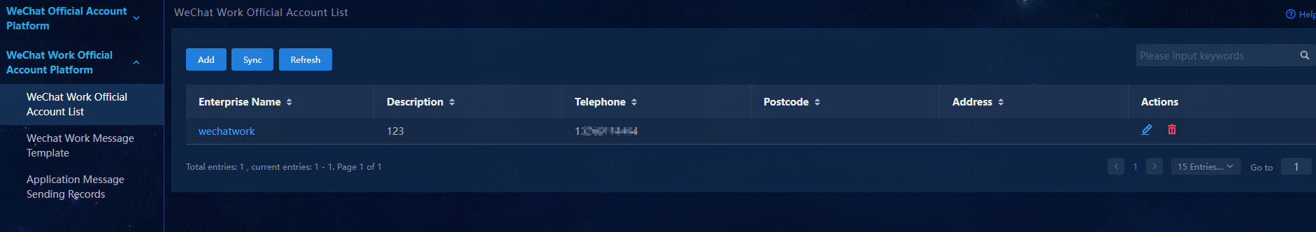
5. Click Add to add a WeCom account.
Figure 64 Adding a WeCom account
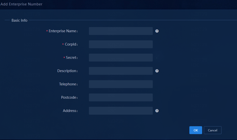
6. Configure the WeCom account:
¡ Enterprise Name: Enter the enterprise name.
¡ CorpId: Enter the company ID you have obtained.
¡ Secret: Enter the app secret you have obtained.
¡ Enter the description, telephone, postcode, and address as needed.
Figure 65 Adding a WeCom account
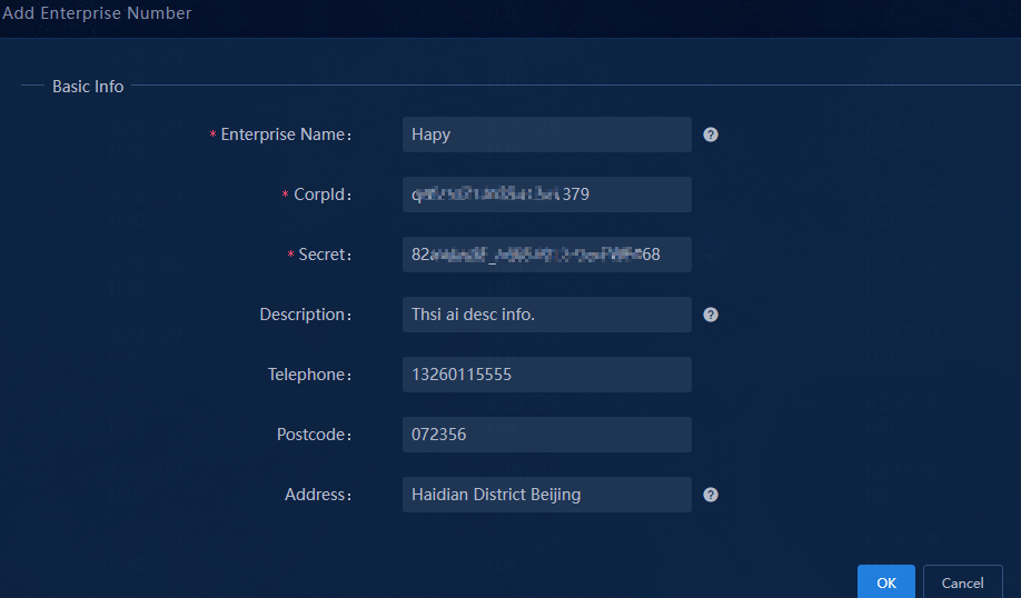
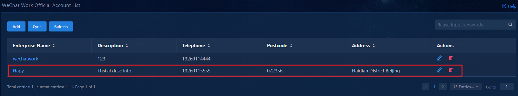
7. Click OK to add the WeCom account.
Figure 66 WeCom account added successfully
Configure a WeCom message template
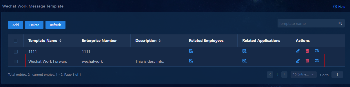
1. Navigate to the WeChat Work Official Account Platform > WeChat Work Message Template page.
Figure 67 WeChat Work Message Template page
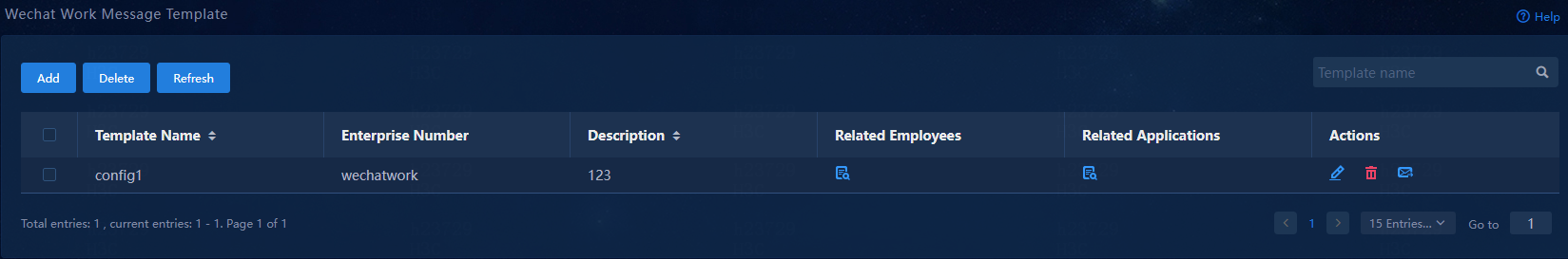
2. Click Add to add a WeCom message template.
Figure 68 Adding a WeCom message template
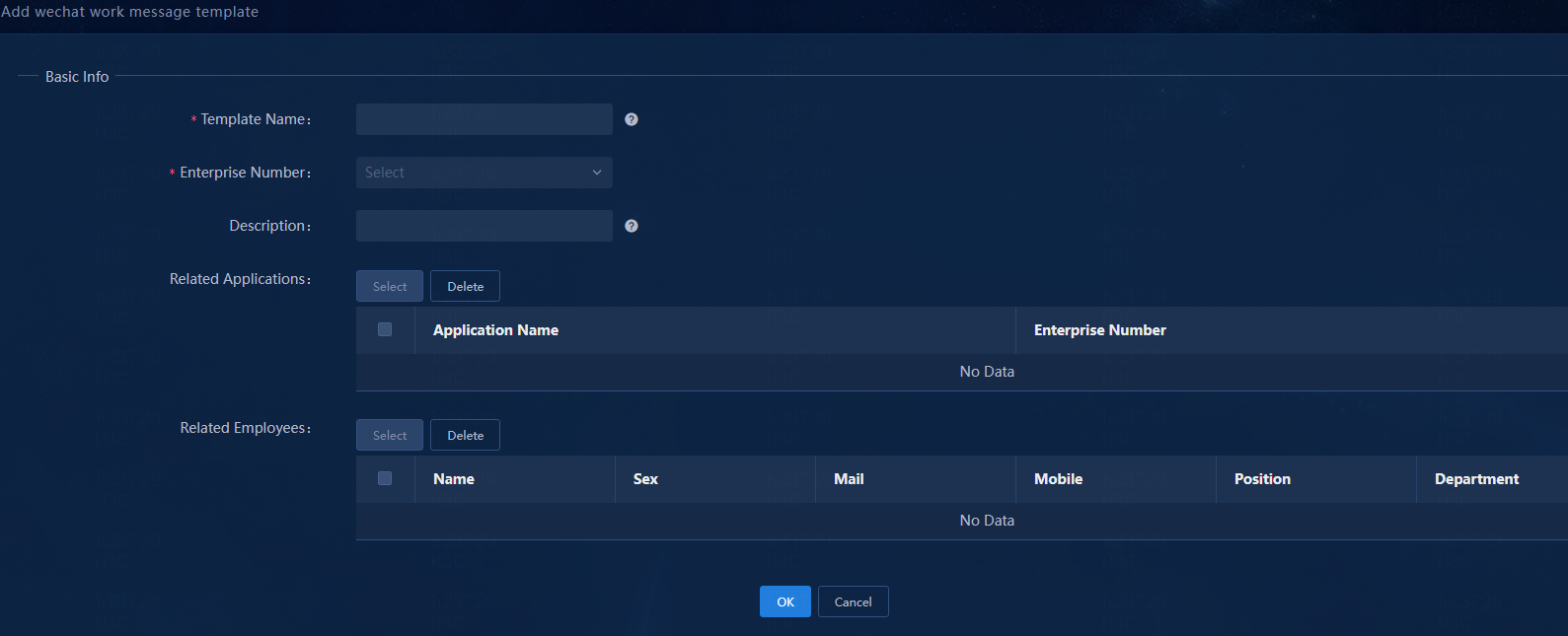
3. Configure the WeCom message template:
¡ Template Name: Enter a message template name, a string of 1 to 32 characters. Valid characters include letters, Chinese characters, digits, underscores (_), hyphens (-), periods (.), backslashes (\), and spaces.
¡ Enterprise Number: Select the corporate account you have added.
¡ Description: Enter a template description, a string of 1 to 32 characters. Valid characters include letters, Chinese characters, digits, underscores (_), hyphens (-), periods (.), backslashes (\), and spaces.
¡ Related Applications: Click Select to select the apps to which messages will be sent.
¡ Related Employees: Click Select to select the alarm notification recipients from among the employees who can access the selected apps. The system automatically synchronizes employee accounts with the WeCom servers every day at 00:00.
Figure 69 Selecting an application
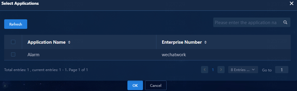
Figure 70 Selecting an employee
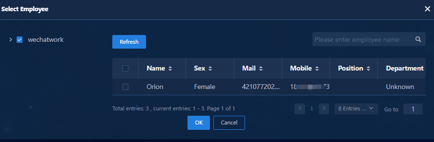
Figure 71 Configuring the WeCom message template
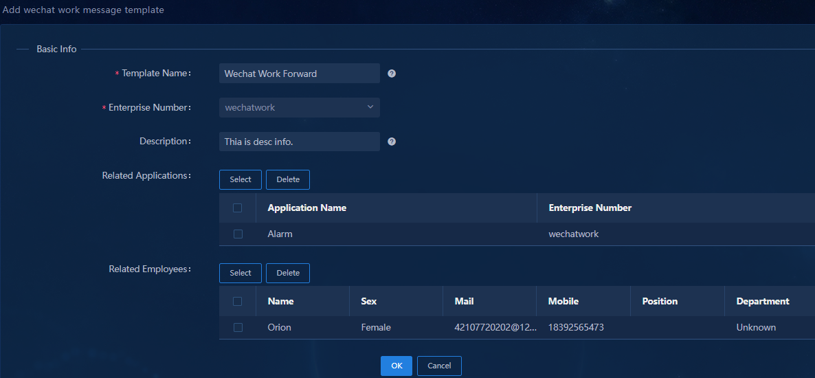
4. Click OK to add the WeCom message template.
Figure 72 WeCom message template added successfully
Configure alarm forwarding via WeCom
1. Navigate to the Monitor> Alarm > Alarm Forwarding Rules page.
2. Click Add to add an alarm forwarding rule.
Figure 73 Adding an alarm forwarding rule
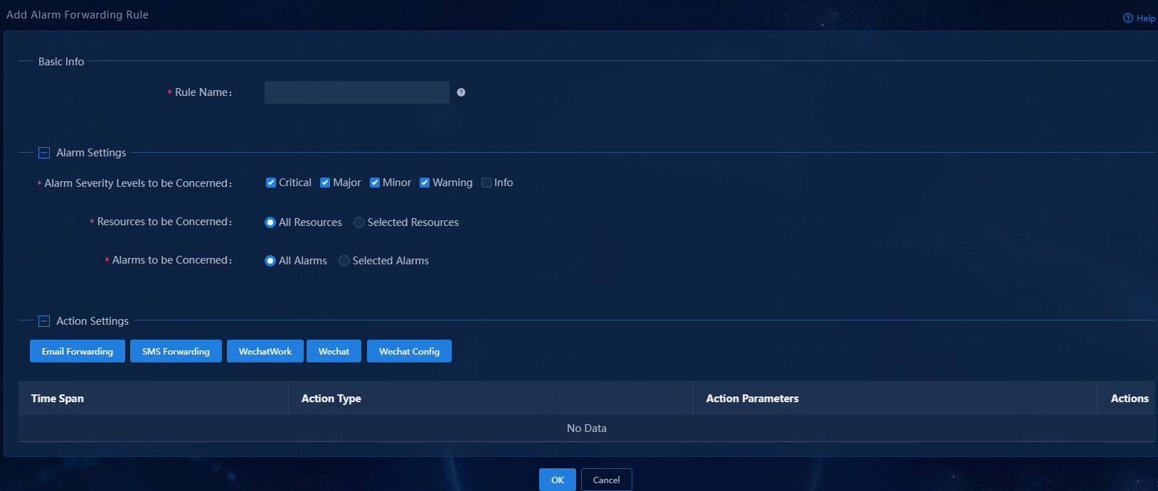
3. Configure an alarm forwarding rule:
¡ Rule Name: Assign a name to the rule.
¡ Alarm Severity Levels to be Concerned: Select alarm severity levels of interest. The system sends alarm notifications only for the specified severity levels. Available options are Critical, Major, Minor, Warning, and Info.
¡ Resources to be Concerned: Select resources of interest. Available options are All Resources and Selected Resources. By default, the All Resources option is selected. Unified Platform sends notifications of alarms generated by all resources. To send notifications of alarms generated by only some of the resources, select the Selected Resources option and then select resource groups or resources of interest. This example uses the All Resources option.
¡ Alarms to be Concerned: Select alarms of interest. Available options are All Alarms and Selected Alarms. By default, the All Alarms option is selected. Unified Platform sends notifications of all alarms. To send notifications of only some of the alarms, select the Selected Alarms option, and then select traps. You can also configure parameters for traps. If you configure parameters for selected traps, Unified Platform sends notifications of only alarms that match the configured parameters. This example uses the All Alarms option.
|
|
NOTE: Traps are one form of SNMP notifications. This document uses traps and SNMP notifications interchangeably. |
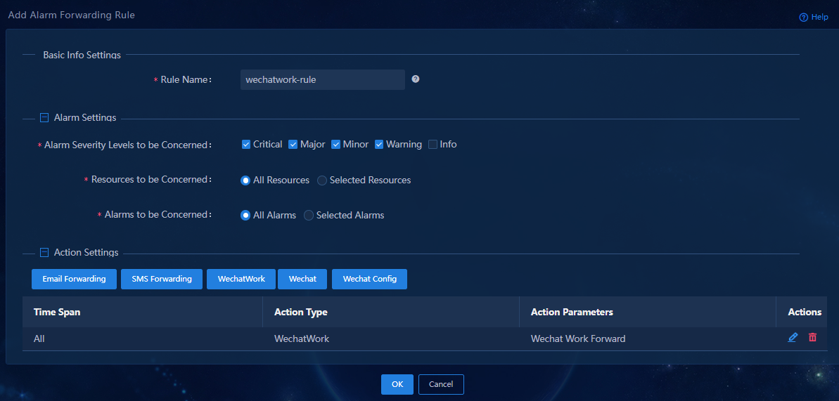
4. In the Action Settings area, click WechatWork. The WeChat work (WeCom) forwarding page opens.
5. Specify the period of time during which alarms are generated. Select the All or Custom option.
¡ All: The system forwards alarms regardless of when they are generated.
¡ Custom: The system forwards only alarms generated within the selected time span.
This example selects the All option.
6. Click Select to select WeCom forwarding message templates, and then click OK.
7. Click OK.
The WeCom alarm forwarding action is added to the action list.
Figure 74 Adding an alarm forwarding rule
8. Click OK.
The alarm forwarding rule is added.
Figure 75 Alarm forwarding rule added successfully
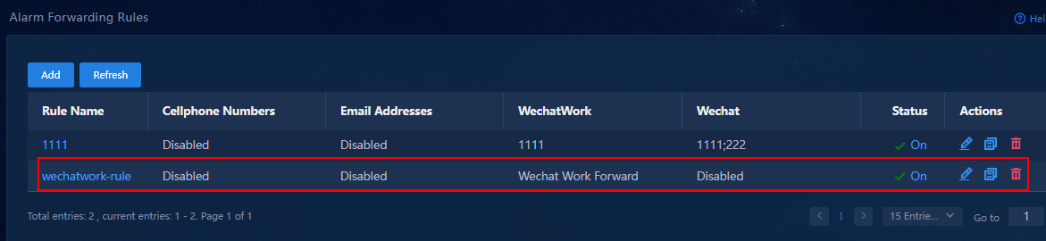
Verify the configuration
1. Verify that the WeCom administrator can receive alarm notifications sent by Unified Platform to the app.
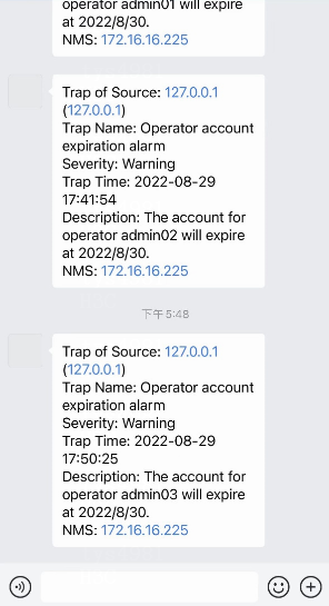
Figure 76 Forwarding alarms to WeCom
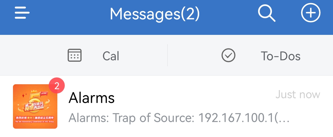
2. Click Alarms to view detailed information about the alarms.
Figure 77 Alarm details
Filter, clear, or acknowledge alarms
Filter alarms by alarm status
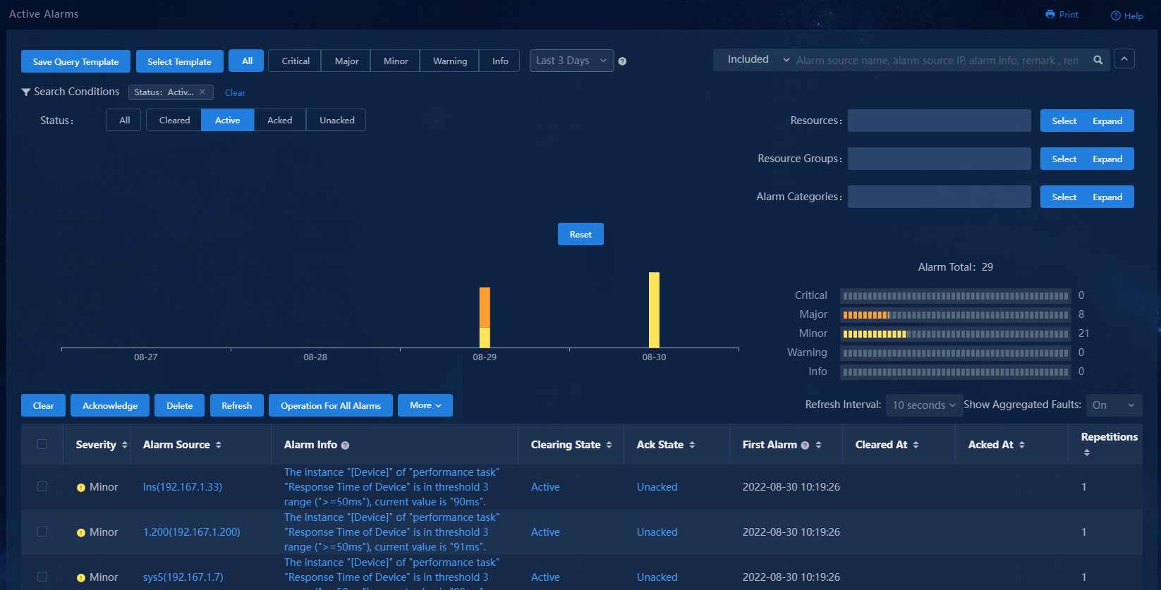
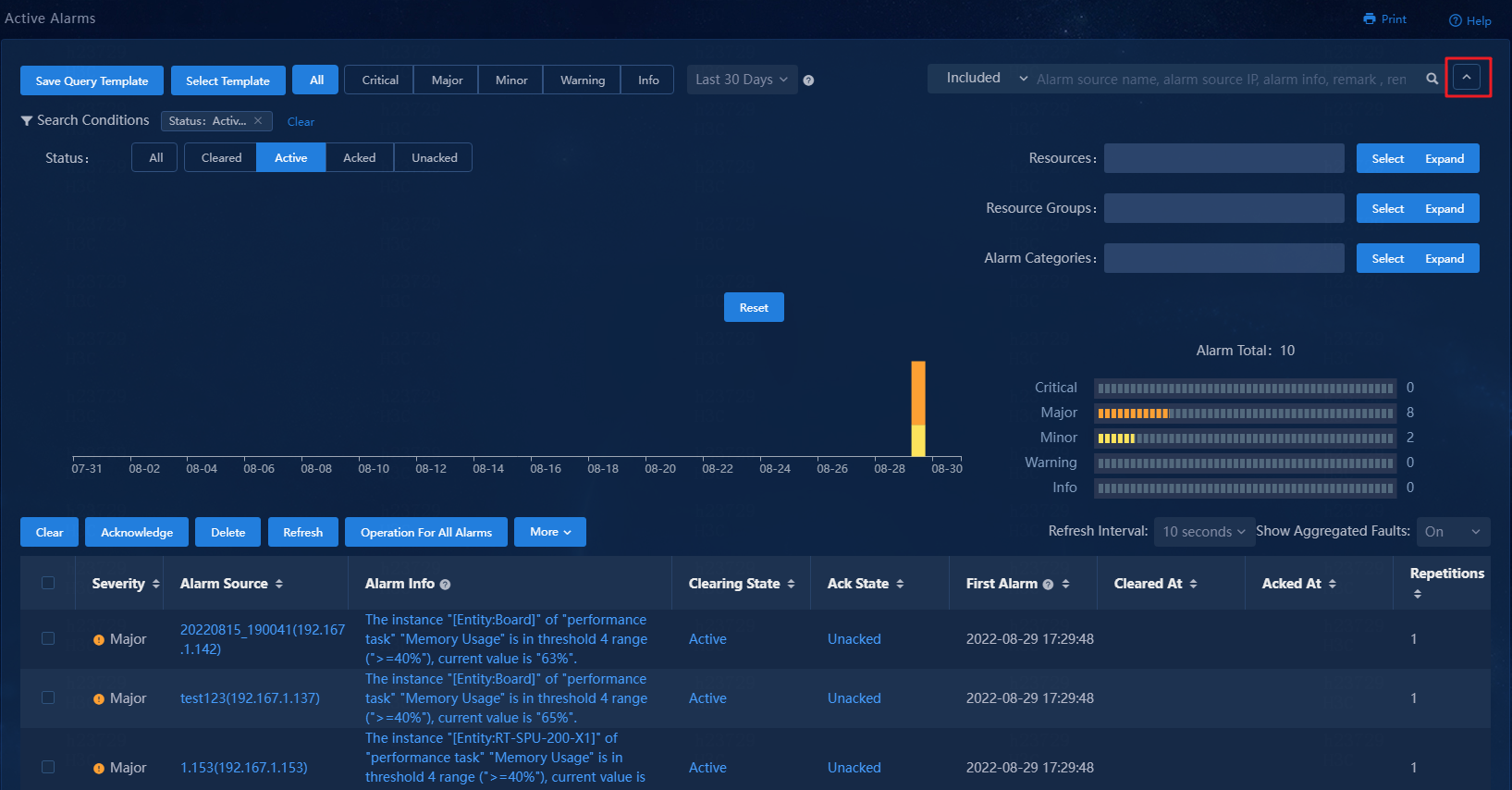
1. Navigate to the Monitor > Alarm > Active Alarms page.
2. Click the Search Conditions link. To view alarms in any states, select All for the Status field. To view alarms in a particular state, select that state.
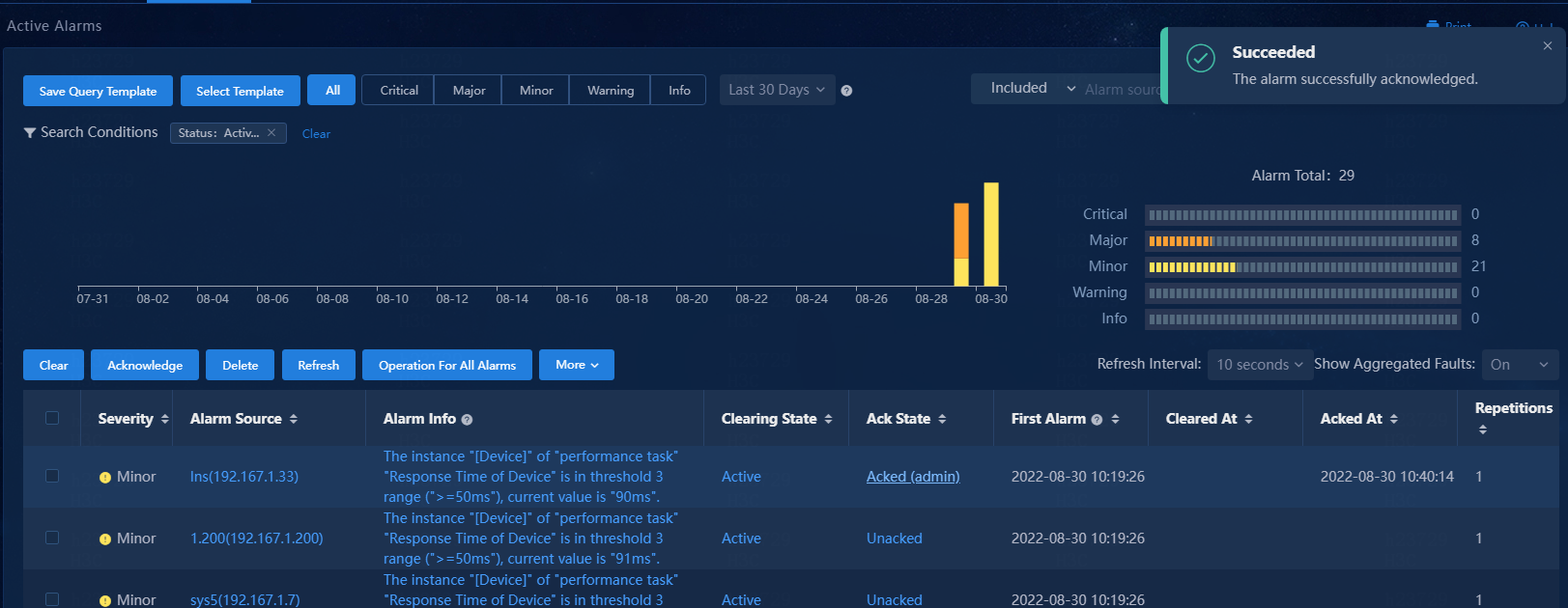
Acknowledge alarms
If you verify that an unacknowledged alarm has been cleared, click the Unacked link in the Ack State column for that alarm to acknowledge it.
Figure 79 Acknowledging an alarm
Filter alarms by using advanced criteria
1. Click the ![]() icon at the upper
right of the page to expand the advanced search area.
icon at the upper
right of the page to expand the advanced search area.
2. Specify the alarm state, resources, resource groups, and alarm categories to display only the matching alarms.
If you select All for the Status field, you can see information about alarms in any state, including the source of each alarm and when they were generated. If an alarm has been cleared, the page also shows when it was cleared. On this page, you can clear, acknowledge, and delete alarms as needed.
3. Click a column heading of the alarm list to sort the alarms in descending or ascending order. You can sort the alarms by the severity, alarm source, first alarm time, cleared at (alarm clearing time), or repetitions field.
Figure 80 Advanced search area
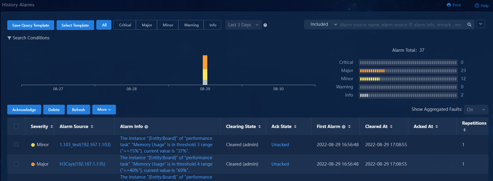
View and delete history alarms
History alarms are alarms that were cleared prior to the present day.
Navigate to the Monitor > Alarm > History Alarms page.
The system displays the following information about each alarm:
· Severity: Severity level of the alarm. Available severity levels are info, warning, minor, major, and critical, from the least severe level to the most severe level.
· Alarm Source: Name and IP address of the device that generated the alarm.
· Alarm Info: Event description.
· Clearing State: Whether the alarm has been cleared. If the alarm has been cleared automatically by the system, this field displays $SYSTEM. If the alarm has been manually cleared by a user, this field displays the username.
· Ack State: Whether the alarm has been acknowledged. If the alarm has been acknowledged, this field displays the username of the user who acknowledged the alarm. If the alarm is not acknowledged, this field displays Unacked.
· First Alarm: Date and time when the alarm first occurred.
· Cleared At: Date and time when the alarm was cleared.
· Repetitions: Number of alarm recurrences before the alarm was cleared.
· Duration: Period of time from when the alarm was generated to when the alarm was cleared.
· Actions: Actions that can be performed on the alarm. You can only delete a history alarm.
Figure 81 History alarms

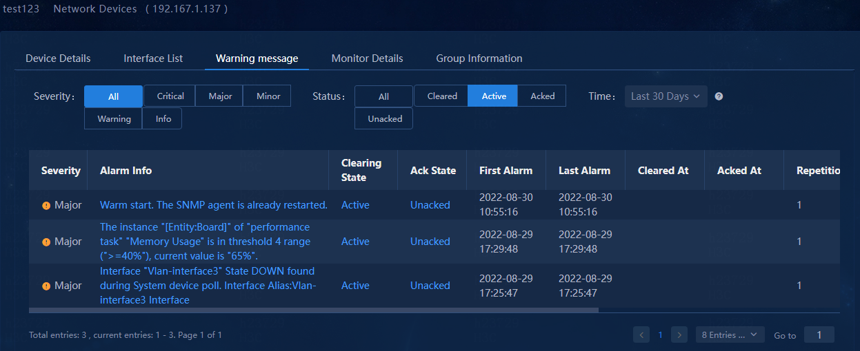
View alarms generated by a device
This feature is available for devices incorporated by the controller.
To view all alarms generated on an incorporated device, click its link in the Alarm Source column of the alarm list.
Figure 82 Alarm source
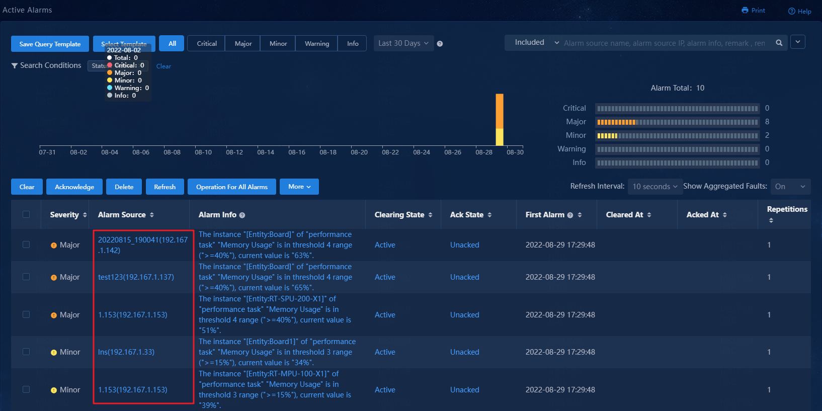
Figure 83 Alarms from a device
View global resource monitoring information
Unified Platform presents a holistic view of resource statistics for the entire network. For example, you can view network-wide statistics for switches, VLANs, and VXLANs.
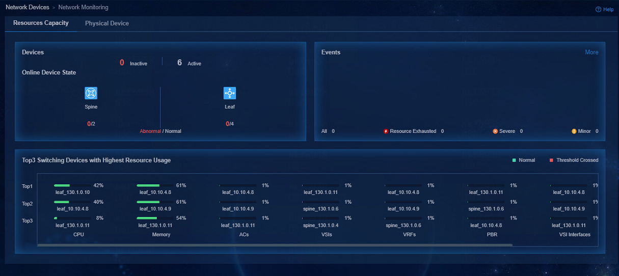
View resource capacity statistics
To view network resource capacity statistics, navigate to the Automation > Campus Network > Network Devices > Monitored > Network Monitoring page.
Figure 84 Network monitoring
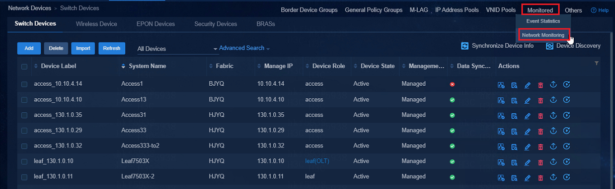
Figure 85 Resources capacity
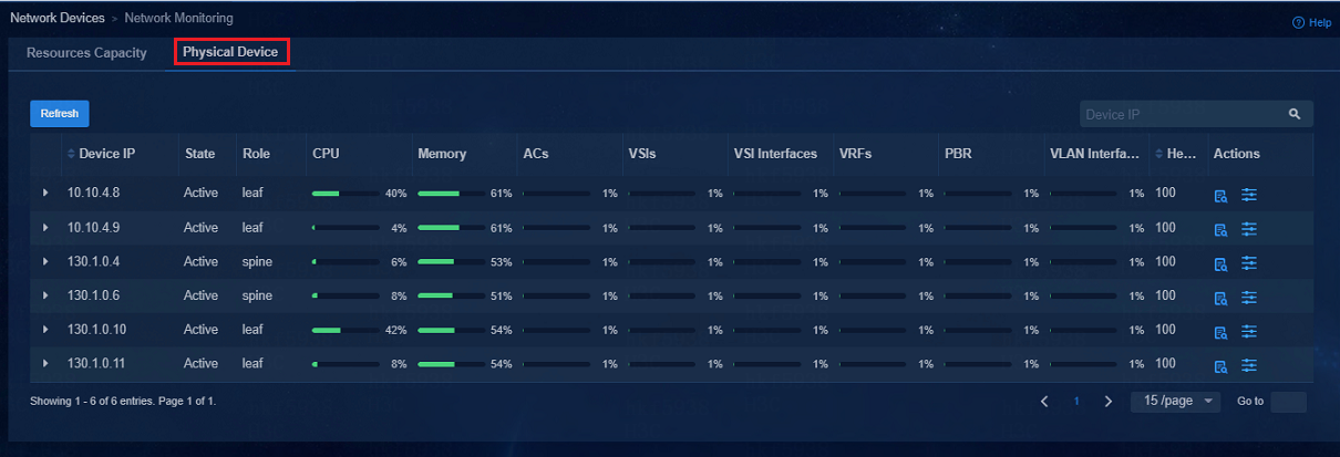
View physical device performance statistics
To view physical device performance statistics, navigate to the Automation > Campus Network > Network Devices > Monitored > Network Monitoring > Physical Device page.
Figure 86 Physical devices
View event statistics
To view event statistics, navigate to the Automation > Campus Network > Network Devices > Monitored > Event Statistics page.
Figure 87 Selecting Event Statistics
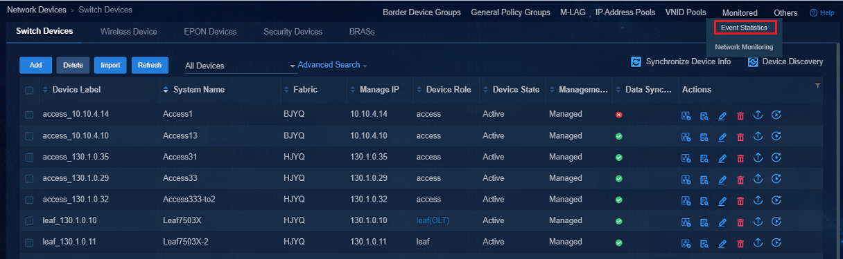
Figure 88 Event statistics

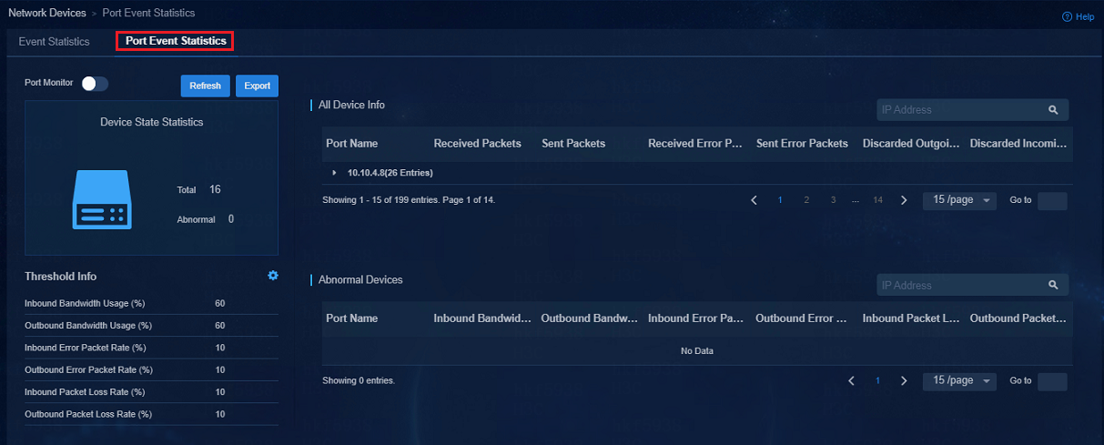
View port event statistics
To view port event statistics, navigate to the Automation > Campus Network > Network Devices > Monitored > Event Statistics > Port Event Statistics page.
Figure 89 Port event statistics
Monitor network devices
To monitor the health and performance of a network device, add that device to the list of monitored devices. The collected statistics can help you make data-driven optimization and scaling decisions to improve network performance.
View the list of monitored network devices
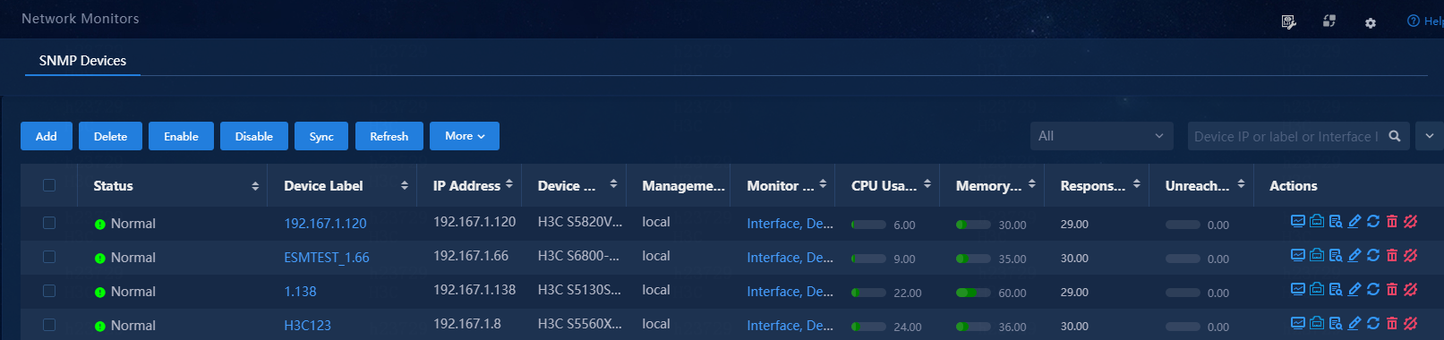
1. Navigate to the Monitor > Monitor List > Network Monitors page.
The system displays the following information for each monitored network device:
¡ Device Label: Device label for the monitored network device. By default, a device label is in resource-type_management-IP format. You can change the device labels as needed for the ease of management.
¡ IP Address: IP address of the network device.
¡ Device Model: Model of the network device.
¡ Monitor Templates: The monitor templates that apply to the network devices.
¡ CPU Usage (%): CPU usage of the network device.
¡ Memory Usage (%): Memory usage of the network device.
¡ Response Time (ms): Delay (milliseconds) for the controller to receive a response from the network device.
¡ Unreachability Radio (%): The percentage of network device reachability test failures in all reachability tests for the present day.
¡ Maintenance State: Whether the network device is in maintenance state. You can place a device in maintenance state for scheduled or non-scheduled maintenance or when you must shut down it.
¡ Actions: Actions that can be performed on the network device, including:
- ![]() : View monitoring
details. This action is available only when the network device is monitored.
: View monitoring
details. This action is available only when the network device is monitored.
- ![]() : View detailed
interface information.
: View detailed
interface information.
- ![]() : View performance
data.
: View performance
data.
- ![]() : Edit monitoring
settings.
: Edit monitoring
settings.
- ![]() : Synchronize data
with the network device.
: Synchronize data
with the network device.
- ![]() : Delete the
network device.
: Delete the
network device.
Enable or disable the maintenance state
1. To disable the
maintenance state for a network device, click the ![]() icon.
icon.
2. To enable the maintenance state for a network device, select the network device, and then select More > Add Maintenance Tag. On the page that opens, configure the parameters, and then click OK. Then, the network device is in In Maintenance state in the specified time span.
Enable or disable monitoring
1. To disable monitoring a network device,
click the ![]() icon. Then, the system stops collecting performance data from the
network device.
icon. Then, the system stops collecting performance data from the
network device.
2. To enable monitoring a network device, click
the ![]() icon. Then, the system starts collecting performance data from the
network device.
icon. Then, the system starts collecting performance data from the
network device.
Figure 90 Monitored network devices
Add a network device to the monitor system
To monitor a network device, perform this task.
Before you add a network device to the monitor system, make sure the device can communicate with the servers that deploy Unified Platform.
To add a network device:
1. Navigate to the Monitor > Monitoring List > Network Monitors page.
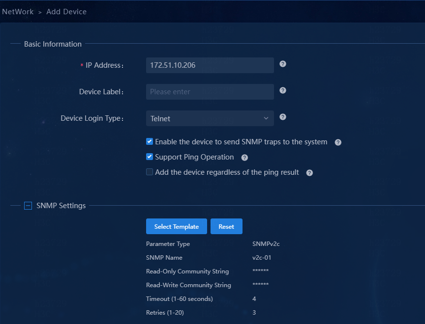
2. Click Add.
3. Enter basic information about the device:
¡ Specify the management IP address of the device.
¡ Enter a device label for the device for the ease of identification.
¡ Select whether to have the device send traps (SNMP notifications) to the system.
¡ Select the support of the device for ping operations.
The device, for example, a firewall, does not support ping operations if it filters or does not respond to the ping packets sent by the system.
¡ Select whether to add the device to the system even if it cannot be pinged.
4. Configure the SNMP, Telnet, and SSH parameters for the device.
Figure 91 SNMP parameters
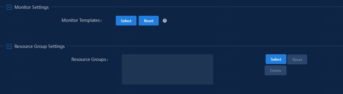
5. In the Monitor Settings area, click Select to select monitor templates for the device.
Figure 92 Selecting monitor templates
6. Click OK.
Review system logs
Navigate to the System > Log Management > System Log Information page. On this page, you can review the system logs for all components of Unified Platform.
Configure system log settings
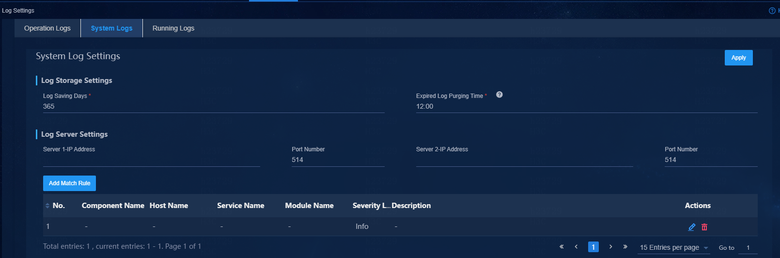
1. Log in to Unified Platform, and then navigate to the System > Log Management > System Log Setting page to configure settings for system log management.
2. Configure the log retention period (Log Saving Days) and time to clear expired log entries (Expired Log Purging Time).
3. Specify the IP address and port number of the log server.
You can specify a maximum of two log servers.
Figure 93 Configuring system log settings
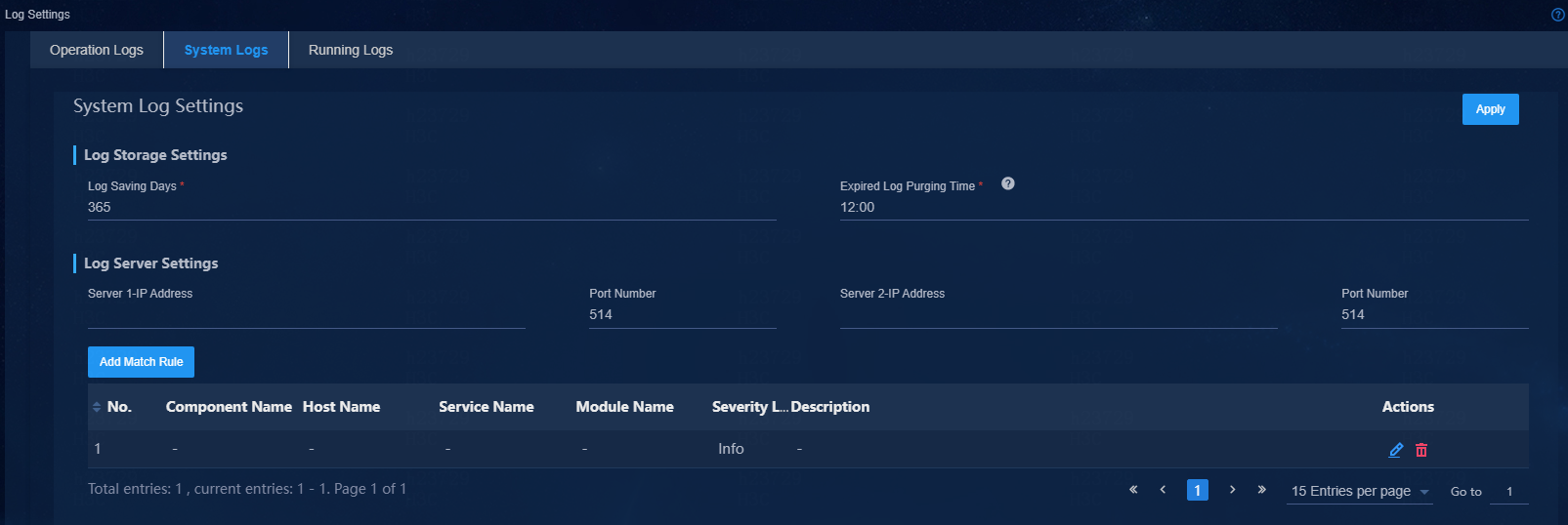
4. To send only a subset of log entries, click Add Match Rule. In the dialog box that opens, select source components of interest and other filtering conditions, and then click Apply.
5. Click Apply.
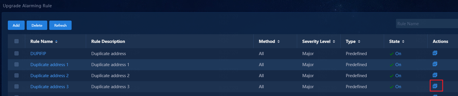
Example: Upgrade system logs to alarm notifications
This example uses the address conflict system log as an example to describe how to upgrade a system log to an alarm notification.
1. Navigate to the Monitor > Alarming Notification > Upgrade Alarming Rule page. This section uses rule Duplicate address 3 as an example.
2. Click the ![]() icon
in the Actions column for Duplicate address 3.
icon
in the Actions column for Duplicate address 3.
Figure 94 Upgrade Alarming Rule page
3. On the page that opens, edit the name and edit values for the Syslog Monitoring Interval (sec) and Syslog Count fields as needed.
Figure 95 Configuring alarm triggering settings

4. Click OK.
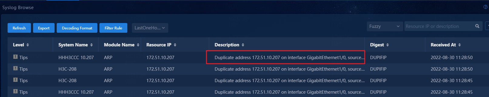
5. To view the system logs, navigate to the Monitor > Alarming Notification > Syslog Browse page.
Figure 96 Viewing system logs
6. Unified Platform matches the syslog against parse templates. The syslog uses template Duplicate address 2. To view parse templates, navigate to the Monitor > Alarming Notification > Parse template page.
Figure 97 Parse templates
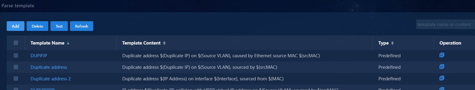
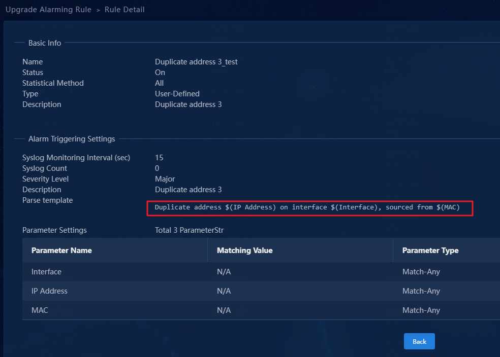
Template Duplicate address 2 corresponds to rule Duplicate address 3_test.
Some rules might use the same parse template. Identify the corresponding rule according to other matching conditions.
Figure 98 Rule details
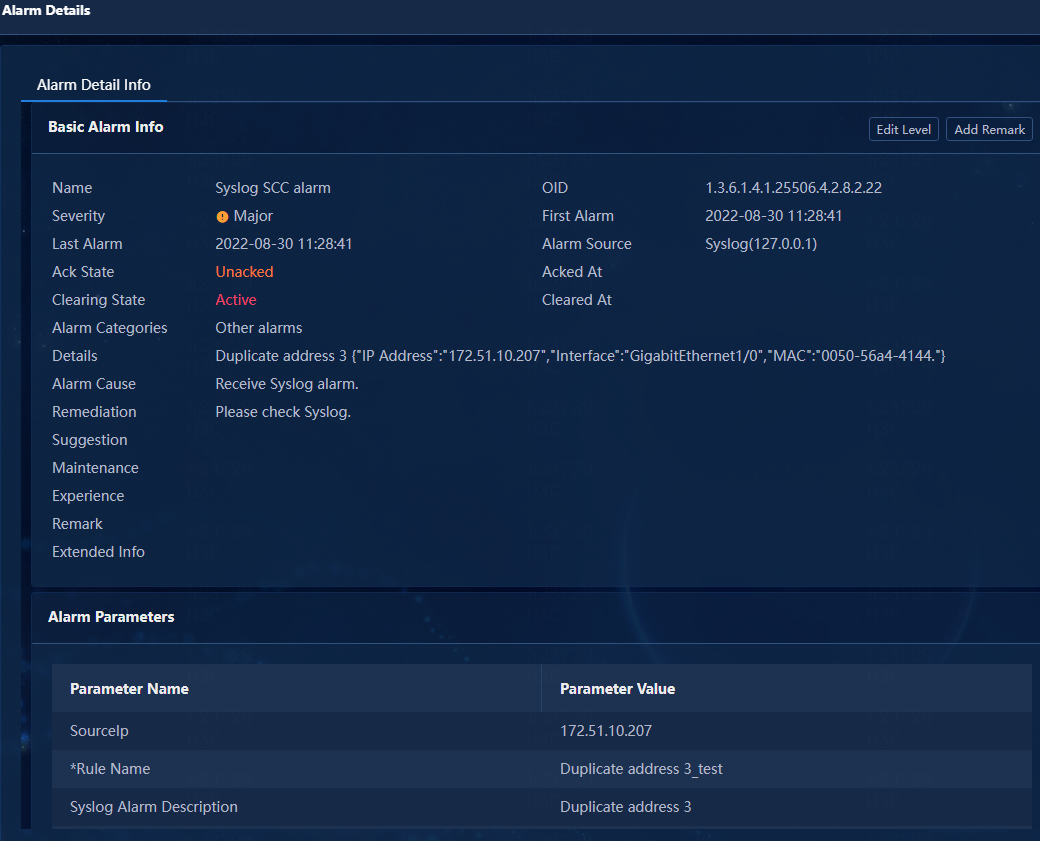
7. Verify that the system log has been upgraded to an alarm notification on the Monitor > Alarm > Active Alarms page.
Figure 99 Active alarm list
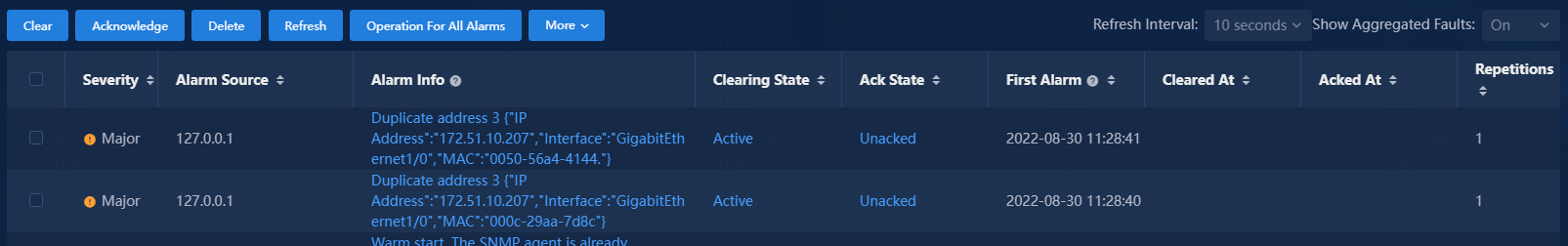
Figure 100 Detailed information about the alarm
Use an external platform for network operations monitoring
Configure Unified Platform to send controller system logs to an external operations monitoring platform
To have Unified Platform send controller system logs to an external operations monitoring platform:
1. Open a Web browser, and then enter http://ip_address:30000/central in the address bar to log in to Unified Platform. The ip_address argument represents the northbound service VIP of the Matrix cluster.
2. Navigate to the System > Log Management > System Log Setting page to configure settings for system log management.
3. Configure the log retention period (Log Saving Days) and time to clear expired log entries (Expired Log Purging Time).
4. Specify the IP address and port number of the log server.
You can specify a maximum of two log servers.
Figure 101 System log settings
5. To send only a subset of log entries, click Add Match Rule. In the dialog box that opens, select source components of interest and other filtering conditions, and then click OK.
6. Click Apply.
Configure the physical devices to send system log messages and SNMP notifications to an external platform
The physical devices (primarily switches and security appliances) can push system log messages and SNMP notifications to an external operations monitoring platform. The platform can also poll the MIBs on the devices to generate alarms.
To configure a physical device to send system log messages and SNMP notifications to an external network operations monitoring system:
1. Enable the information center and the SNMP agent.
[device] info-center enable
[device] snmp-agent
2. Configure a read-only community string and a read and write community string. Then, enable SNMP versions. This example enables all SNMP versions.
[device] snmp-agent community read public
[device] snmp-agent community write private
[device] snmp-agent sys-info version all
3. Enable SNMP notifications and enable SNMP notifications for service modules, for example, BGP.
[device] snmp-agent Trap enable
[device] snmp-agent Trap enable bgp
4. Specify the IP address of the external operations monitoring platform for receiving SNMP notifications. Optionally, configure authentication for security purposes.
[device] snmp-agent target-host Trap address udp-domain 1.1.1.1 params securityname public v2c
5. Specify the IP address of the external operations monitoring platform for receiving log messages.
[device] info-center loghost 1.1.1.1
|
|
IMPORTANT: Make sure the port number you specify is the same as that configured on the log host. By default, service port number 514 is used if you do not specify one. |
Obtain alarms reference documents
Obtain alarm or log messages reference
Obtain alarms or log messages references
For information about obtaining alarms generated by Unified Platform, see "Manage alarms on Unified Platform."
To obtain the system log reference for a product selected in the AD-Campus 6.2 solution:
1. Go to http://www.h3c.com/en/Technical_Documents.
2. Select the product category and then product series of interest. On the documentation page for the product series, identify the system log reference in the reference guides category. For example, to obtain the SeerEngine-Campus system log reference, click the above website, and then select Support > Technical Documents > SDN > H3C SeerEngine-Campus.
System log messages references for related products
Use Table 1 to identify the log message references and modules related to the solution.
For information about EIA, WSM, and vDHCP log messages, see "Appendix B Logs."
Table 1 System log messages references for related products
|
Product |
Document title |
Solution-related modules |
|
SeerEngine-Campus |
H3C SeerEngine-Campus System Log Messages Reference |
Campus, CON_LICENSE, CON_MONITOR, CON_NETCONF, CON_NetworkMonitor, CON_OAM, CON_OPENFLOW, CON_PortMonitor, CON_REGION, CON_SNMP, CON_SYSTEM, CON_TEAM, CON_USER, DHCP, IDM, NEM, ServiceChain, VSM |
|
S12500G |
H3C S12500G-AF System Log Messages Reference |
ACL, BGP, M-LAG, ETHDRNI, ETHOAM, FIB, FILTER, IP6ADDR, IP6FW, IPADDR, IPFW, ISIS, ISSU, L2VPN, LAGG, LLDP, MFIB, ND, NETCONF, NQA, OFP, OSPF, OSPFv3, PBR, QOS, RM, SNMP, SYSEVENT, SYSLOG, VCF, VXLAN |
|
S10500X |
H3C S10500X System Log Messages Reference |
|
|
S7500X |
H3C S7500X System Log Messages Reference |
|
|
S6525XE-HI |
H3C S6550XE-HI Switch Series System Log Messages Reference |
|
|
S6520X-HI |
||
|
S6520X-EI |
||
|
S5560X-HI |
H3C Campus Fixed-Port Switches System Log Messages Reference |
|
|
S5560X-EI |
H3C S5560X-EI Switch Series System Log Messages Reference-6W100 |
|
|
S6520X-EI |
||
|
S5130-HI |
||
|
S5130-EI |
||
|
S5130S-HI |
||
|
S5130S-EI |
Obtain trap definitions from Unified Platform
For information about obtaining trap definitions from Unified Platform, see "Repeated events alarm
|
System alarm system has received $3 alarms about the event ($4) of device $6($5) from $1 to $2. |
|
|
This message occurs if the alarm system has received repeated messages about an event from a device. |
|
Event alarms received from unmanaged devices
|
System alarm system has received $3 alarms from the unmanaged device from $1 to $2. |
|
|
The alarm system has received a large number of events from unmanaged devices. |
|
Unknown event alarm
|
The alarm system has received a large number of unknown traps. |
|
|
Add the definitions of the unknown traps to the system for management. |
Intermittent failure alarm
|
Check for service anomalies that might result from the intermittent failure. |
Lower-level NMS reported alarm
|
Lower-level NMS 172.51.2.6 alarm: Interface Ten-GigabitEthernet2/0/14 became down. |
|
|
The upper-level NMS received an alarm of interest from a lower-level NMS. |
|
Lower-level NMS reported recovery event
|
Lower-level NMS 172.51.2.6 recovery: Interface Ten-GigabitEthernet2/0/14 became up. |
|
|
The upper-level NMS received a recovery event of interest from a lower-level NMS. |
|
Appendix A Alarm and trap management on Unified Platform
Manage alarms on Unified Platform
Manage system alarms
The system generates alarms when the alarm conditions are met or when a lower-level node reports alarms. The following information describes how to use and manage system alarms and provides sample alarm messages and recommended actions.
View system alarms
Log in to Unified Platform, and then navigate to the Monitor > Alarm page.
On this page, you can view and manage all alarms generated in the system. Table 2 describes the fields in an alarm entry.
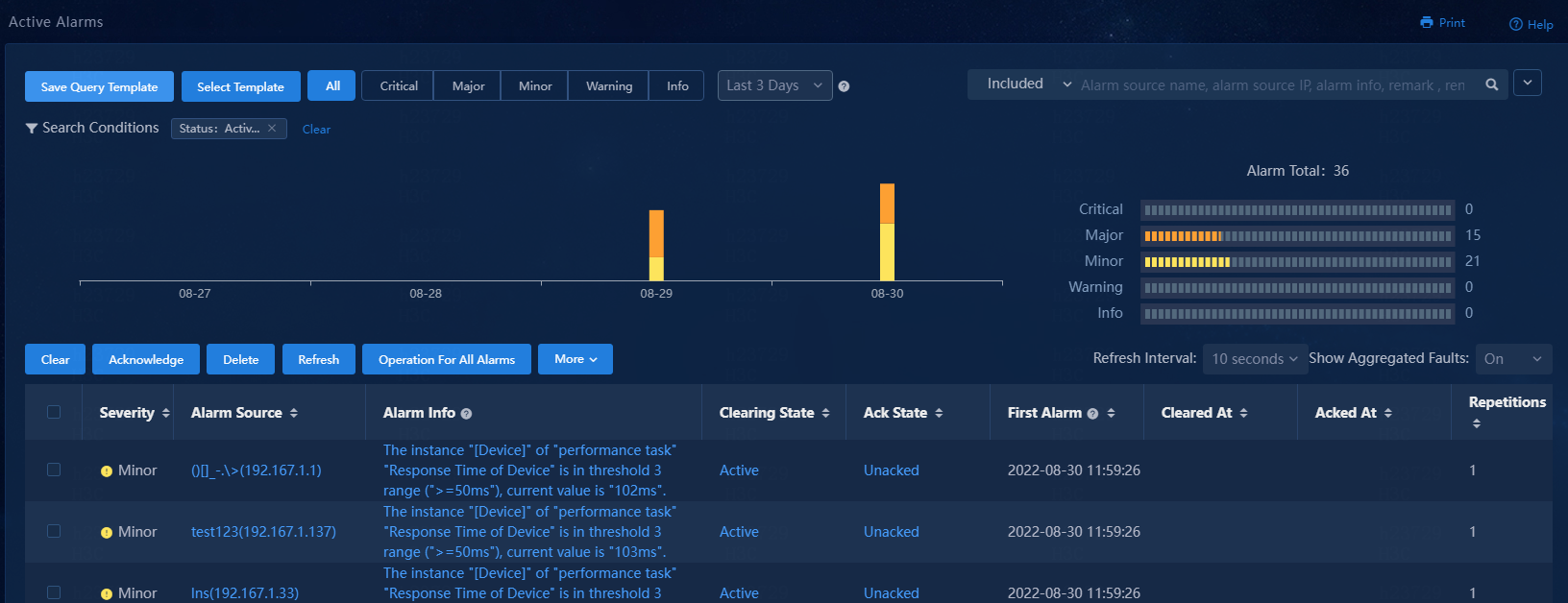
Active alarms
The active alarms page intuitively displays alarms that are still present in the system and alarms that have been cleared in the present day, in tables and graphs.
On this page, you can get a quick holistic view of the network health and use the basic and advanced search functions to identify alarms of interest with ease.
History alarms
The History Alarms page intuitively displays alarms that have been cleared prior to the present day, in tables and graphs.
On this page, you can get a quick holistic view of network health history and use the basic and advanced search functions to identify history alarms of interest with ease.
Figure 103 History alarms
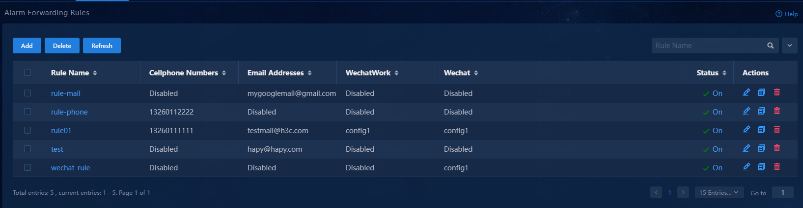
Alarm forwarding
Configure alarm forwarding to have the system notify maintenance staff of alarms via email or SMS for quick removal of network issues.
Figure 104 Alarm forwarding rules
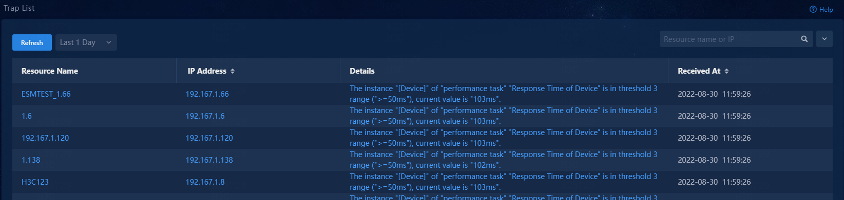
Trap list
The Trap List page provides basic and advanced filters for quick and accurate search for traps of interest.
Figure 105 Trap list
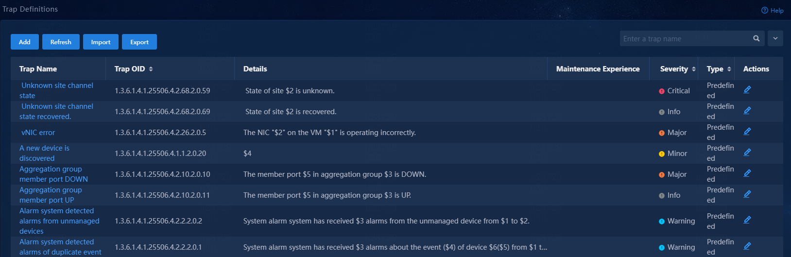
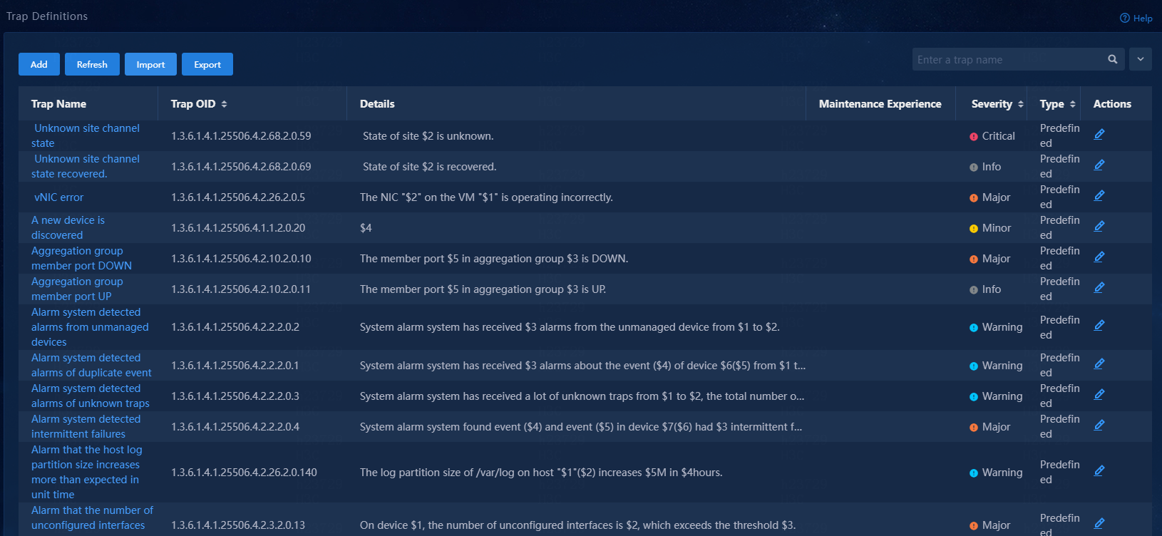
Trap definitions
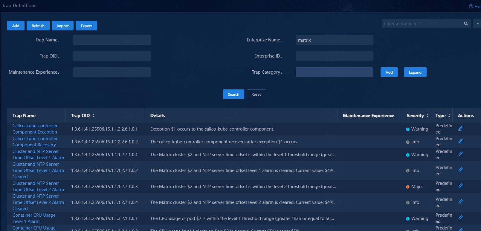
This page displays all traps defined in the system, including predefined and custom traps. You can add new trap definitions or edit existing ones as needed.
Figure 106 Trap definitions
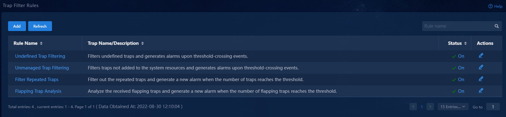
Trap filter rules
This page displays all trap filter rules defined in the system, including predefined and custom trap filter rules. You can add new trap filter rules or edit existing ones as needed.
Figure 107 Trap filter rules page
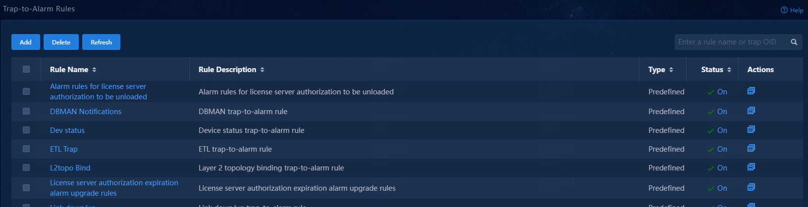
Trap-to-alarm rules
On this page, you can define rules to escalate traps to alarms based on keywords, trap sources, trap types, and time ranges. The system automatically escalates a trap to an alarm if it matches a trap-to-alarm rule.
Figure 108 Trap-to-alarm rules
|
Field |
Description |
|
Severity |
Alarm severity level. The severity level of an alarm can be critical, major, minor, warning, or info, from the most severe to the least severe. Alarms excluding the threshold-triggered alarms have only one severity level. |
|
Ack State |
Whether the alarm has been administratively acknowledged. After you receive an alarm and identify its reason, you can manually change its state to Acked. |
|
Clearing State |
Whether the alarm has been cleared. An alarm changes to the cleared state when the alarm condition is removed. If an alarm source is deleted, the system deletes all alarms from that source. |
|
Alarm Source |
Name and IP address of the entity that generated the alarm. This field displays only the IP address if the alarm resource is not incorporated in the system. |
|
Alarm Info |
Detailed information about the event or error that triggered the alarm. |
|
First Alarm |
Date and time when the alarm was first triggered. |
|
Cleared At |
Date and time when the alarm was cleared. |
1. Log in to Unified Platform, and then navigate to the Monitor > Alarm page.
2. On the page that opens, perform the following tasks to manage alarms:
¡ To filter alarms of interest, select a filtering criterion, and then click OK.
The system then displays only matching alarms.
By default, the system displays all alarms.
¡ To obtain the most recent alarm information, click Refresh.
¡ To delete alarms, select the target alarms, and then click Delete.
¡ To acknowledge or unacknowledge an alarm, click Acked or Unacked, respectively, in the Ack State column for that alarm.
¡ To export alarms, click More, and then select Export to export all filter-matching alarms as a file.
By default, the alarms file is exported to the download path for your browser.
To send alarm notifications for the specified severity levels to email addresses or phones, configure alarm forwarding.
To configure alarm forwarding:
1. Log in to Unified Platform, and then navigate to the Monitor > Alarm > Alarm Forwarding Rules page.
2. Specify a rule name, select the alarm severity levels, resources, and alarms of interest.
3. Click Action Settings, add phone numbers or emails, and then click OK.
|
|
NOTE: The system does not support alarm notifications via WeChat. |
Using the alarm messages reference
The alarm messages reference categorizes system alarm messages by alarm type. This document explains messages in tables. Table 3 describes information provided in these tables.
Table 3 Message explanation table fields
|
Item |
Content |
Example |
|
Message text |
Presents the message description. |
Current CPU usage $2 exceeded alarm threshold $1 |
|
Variable fields |
Briefly describes the variable fields in the order in which they appear in the message text. The variable fields are numbered in the "$Number" form to help you identify their location in the message text. |
$1: CPU usage threshold. $2: Current CPU usage in percentage. |
|
Severity level |
Provides the severity level of the message. |
Major |
|
Example |
Provides a real message example. |
Current CPU usage 86% exceeded alarm threshold 85% |
|
Explanation |
Explains the message, including the event or error cause. |
When the CPU usage of the device reaches the CPU usage threshold, the system sends a log message for the event. When the CPU usage of the device drops below the threshold, the system sets the state of the alarm to cleared. The thresholds for CPU usage are configurable. By default, the thresholds are as follows: · For the H3C MSR router series, only the major threshold is set, and the threshold value is 99%. · For devices of other models, the minor threshold is 85%, and the major threshold is 90%. |
|
Recommended action |
Provides recommended actions. For informational messages, no action is required. |
If an alarm condition persists for a long time, contact H3C Support |
Alarm messages reference
Repeated events alarm
|
Message text |
System alarm system has received $3 alarms about the event ($4) of device $6($5) from $1 to $2. |
|
Variable fields |
$1: Fault Start Time $2: Stop Time $3: Times $4: Repeat Event Name $5: Device IP $6: Device Name |
|
Severity level |
Major |
|
Example |
System alarm system has received two alarms about the event (cold start) of device A-lab-HuiJu (192.168.54.173) from 2021-08-25 23:53:49 to 2021-08-25 23:53:50. |
|
Explanation |
This message occurs if the alarm system has received repeated messages about an event from a device. |
|
Recommended action |
Identify the cause and remove the issue. |
Event alarms received from unmanaged devices
|
Alarm Info |
System alarm system has received $3 alarms from the unmanaged device from $1 to $2. |
|
Variable fields |
$1: Fault Start Time $2: Stop Time $3: Times |
|
Severity Level |
Warning |
|
Example |
System alarm system has received 3 alarms from the unmanaged device from 2021-08-25 23:53:49 to 2021-08-25 23:53:50. |
|
Explanation |
The alarm system has received a large number of events from unmanaged devices. |
|
Recommended action |
Add the unmanaged devices to the system for management. |
Unknown event alarm
|
Message text |
System alarm system has received a lot of unknown traps from $1 to $2, the total number of unknown traps exceeded the threshold ($3). |
|
Variable fields |
$1: Fault Start Time $2: Stop Time $3: Times |
|
Severity level |
Warning |
|
Example |
System alarm system has received a lot of unknown traps from 2021-08-25 23:53:49 to 2021-08-25 23:53:50, the total number of unknown traps exceeded the threshold (3). |
|
Explanation |
The alarm system has received a large number of unknown traps. |
|
Recommended action |
Add the definitions of the unknown traps to the system for management. |
Intermittent failure alarm
|
Message text |
System alarm system found event ($4) and event ($5) in device $7($6) had $3 intermittent failures from $1 to $2. |
|
Variable fields |
$1: Fault Start Time $2: Stop Time $3: Times $4: Flash Event $5: Flash Relative Event $6: Device IP $7: Device Name |
|
Severity level |
Major |
|
Example |
System alarm system found event (link DOWN) and event (link DOWN) in device A-lab-HuiJu (192.168.54.173) had 2 intermittent failures from 2021-08-25 23:53:49 to 2021-08-25 23:53:50. |
|
Explanation |
A fault comes and goes quickly. |
|
Recommended action |
Check for service anomalies that might result from the intermittent failure. |
Lower-level NMS reported alarm
|
Message text |
Lower-level NMS $L alarm: $4 |
|
Variable fields |
$1: Device ID $2: Fault OID $3: POS Info $4: Trap Description $5: Alarm Level $6: Device IP $7: Device Name $8: Serial Number |
|
Alarm Severity Level |
Warning |
|
Example |
Lower-level NMS 172.51.2.6 alarm: Interface Ten-GigabitEthernet2/0/14 became down. |
|
Explanation |
The upper-level NMS received an alarm of interest from a lower-level NMS. |
|
Recommended action |
Access the lower-level NMS to review information about the device that reported the alarm and locate the root cause of the issue. |
Lower-level NMS reported recovery event
|
Message text |
Lower-level NMS $L recovery: $4 |
|
Variable fields |
$1: Device ID $2: Fault OID $3: POS Info $4: Trap Description $5: Alarm Level $6: Device IP $7: Device Name $8: Serial Number |
|
Severity level |
Info |
|
Example |
Lower-level NMS 172.51.2.6 recovery: Interface Ten-GigabitEthernet2/0/14 became up. |
|
Explanation |
The upper-level NMS received a recovery event of interest from a lower-level NMS. |
|
Recommended action |
No action is required. |
Obtain trap definitions from Unified Platform
Log in to Unified Platform
1. Open a Web browser, and then enter http://ip_address:30000/central in the address bar.
The ip_address argument represents the northbound service VIP of the Matrix cluster.
2. Log in to Unified Platform.
Make sure the user account you use has the privilege of viewing trap definitions.
View trap definitions
Navigate to the Monitor > Alarm > Traps > Trap Definitions page.
The page displays all trap definitions in the system.
Figure 109 Trap definitions
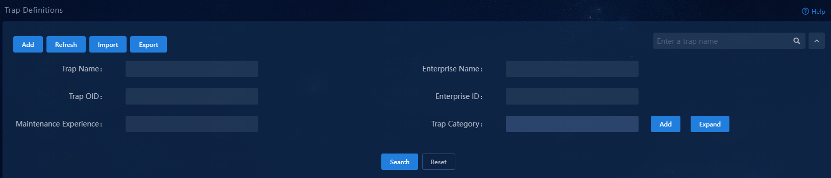
Filter trap definitions
To filter trap definitions, click the chevron to the right of the search field, and then select a filtering criterion.
Available filtering criteria include trap name, enterprise name, trap OID, enterprise ID, maintenance experience, and trap category.
Figure 110 Filtering trap definitions
For example, if you select the enterprise name criterion, and then enter the matrix keyword, the system displays all trap definitions available for Matrix.
Figure 111 Filtering Matrix trap definitions
Commonly used filtering criteria
|
Trap definition |
Filtering criterion |
|
Matrix-related trap definitions |
Enterprise name: matrix |
|
Portal-related trap definitions |
Enterprise name: portal enterprise id |
|
License server |
Enterprise name: License Server enterprise id |
Appendix B Logs
Introduction to vDHCP logs
Operation logs record system operations and configuration modifications, such as device operations (adding, editing, or deleting a device) and policy configuration. Operation log messages include operation description, result, and failure reasons, and provide reference for system analysis and maintenance.
This document assumes that the readers are familiar with data communications technologies and H3C vDHCP products.
Viewing operation logs
The vDHCP product is deployed based on Unified Platform.
To view operation logs:
1. Log in to Unified Platform, and then navigate to the System > Log Management > Operation Log Information page.
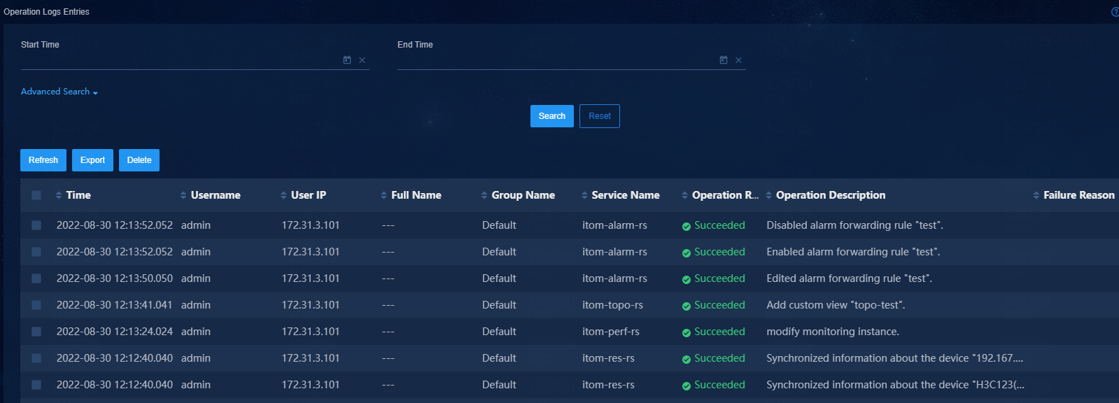
Table 4 Operation log elements
|
Element |
Description |
|
Time |
Date and time when the log message was generated. |
|
Username |
Name of the user that triggered the log generation. |
|
User IP |
IP address of the terminal where the user performed the operation. |
|
Service Name |
Name of the service that produced the message. |
|
Operation Result |
Operation result: Succeeded or Failed. |
|
Operation Description |
Text string that contains detailed information about the operation. |
|
Failure Reason |
Possible reasons for an operation failure. |
Syslog message format
vDHCP can send operation logs to syslog servers through the syslog protocol.
To set the IP addresses and port numbers of syslog servers:
1. Navigate to the System > Log Management > Setting Operation Log page.
2. Set the IP addresses and port numbers of syslog servers.
By default, controllers send operation logs in the following format:
<PRI>TIMESTAMP Hostname Origin/severity/Keywords CONTENT
Table 5 Syslog message elements
|
Element |
Description |
|
<PRI> |
Priority identifier. It is calculated by using the following formula: Priority identifier=facilityx8+severity Where: · facility represents the programming module defined by syslog. · severity represents the syslog message severity level. For more information, see Table 7. |
|
TIMESTAMP |
Date and time when the event occurred. |
|
Hostname |
Name or IP address of the server or VM where the controller that generated the message resides. |
|
Origin |
Name of the service module that generated the message. |
|
Keywords |
Keywords of the message that facilitate searching or memorizing. |
|
CONTENT |
Text string that contains detailed information about the operation, in the following format: User=username IP=user IP Description=description Result=result Cause=operation failure causes |
Table 6 lists all service modules that might produce operation log messages.
|
Service module name |
Description |
|
DHCP |
DHCP module. |
|
DHCPS |
IPv4 DHCP server module. |
|
DHSPS6 |
IPv6 DHCP server module. |
|
VRRP |
VRRP module. |
Syslog messages are classified into eight severity levels from 0 to 7. The lower the number, the higher the severity, as shown in Table 7.
Table 7 Syslog message severity levels
|
Level |
Severity |
Description |
|
0 |
Emergency |
The system might be unusable. |
|
1 |
Alert |
Action must be taken immediately. |
|
2 |
Critical |
Critical condition. |
|
3 |
Error |
Error condition. |
|
4 |
Warning |
Warning condition. |
|
5 |
Notice |
Normal but significant condition. |
|
6 |
Informational |
Informational message. |
|
7 |
Debug |
Debugging message. |
Using this document
This document categorizes operation log messages by service module. This document explains messages in tables. Table 8 describes information provided in these tables.
Table 8 Message explanation table contents
|
Item |
Content |
Example |
|
Keyword |
Summary of the message that facilitates searching or memorizing. |
DELETE_FABRIC_OP |
|
Message text |
Presents the message description. |
Deleted fabric: $1 |
|
Variable fields |
Briefly describes the variable fields in the order that they appear in the message text. The variable fields are numbered in the "$Number" form to help you identify their location in the message text. |
$1: Fabric UUID. |
|
Example |
Provides a real message example. |
Deleted fabric: 218b5f2f-e435-4365-a1ab-0eaa03b7fa19 |
|
Explanation |
Explains the message. |
A fabric was deleted. |
|
Recommended action |
Provides recommended actions. |
Delete unnecessary files to release resources. |
DHCP
This section contains DHCP messages.
DHCP_NORESOURCES
|
Keyword |
DHCP_NORESOURCES |
|
Message text |
Failed to apply filtering rules for DHCP packets because hardware resources are insufficient. |
|
Variable fields |
N/A |
|
Severity level |
3 |
|
Example |
DHCP/3/DHCP_NORESOURCES: Failed to apply filtering rules for DHCP packets because hardware resources are insufficient. |
|
Explanation |
The system failed to apply filtering rules for DHCP packets because the hardware resources are insufficient. |
|
Recommended action |
Release hardware resources, and then apply the rules again. |
DHCP_NOTSUPPORTED
|
Keyword |
DHCP_NOTSUPPORTED |
|
Message text |
Failed to apply filtering rules for DHCP packets because some rules are not supported. |
|
Variable fields |
N/A |
|
Severity level |
3 |
|
Example |
DHCP/3/DHCP_NOTSUPPORTED: Failed to apply filtering rules for DHCP packets because some rules are not supported. |
|
Explanation |
The system failed to apply filtering rules for DHCP packets because some rules are not supported on the device. |
|
Recommended action |
No action is required. |
DHCPS
This section contains DHCP server messages.
DHCPS_ALLOCATE_IP
|
Keyword |
DHCPS_ALLOCATE_IP |
|
Message text |
DHCP server received a DHCP client’s request packet on interface [STRING], and allocated an IP address [IPADDR](lease [UINT32] seconds) for the DHCP client(MAC [MAC]) from [STRING] pool. |
|
Variable fields |
$1: Name of the interface on which DHCP server is configured. $2: IPv4 address assigned to the DHCP client. $3: Lease duration of the assigned IPv4 address. $4: MAC address of the DHCP client. $5: Name of the address pool to which the assigned IPv4 address belongs. |
|
Severity level |
5 |
|
Example |
DHCPS/5/DHCPS_ALLOCATE_IP: DHCP server received a DHCP client’s request packet on interface Ethernet0/2, and allocated an IP address 1.0.0.91(lease 86400 seconds) for the DHCP client(MAC 0000-0000-905a) from p1 pool. |
|
Explanation |
The DHCP server assigned an IPv4 address with a lease to a DHCP client. |
|
Recommended action |
No action is required. |
DHCPS_CONFLICT_IP
|
Keyword |
DHCPS_CONFLICT_IP |
|
Message text |
A conflict IP [IPADDR] from [STRING] pool was detected by DHCP server on interface [STRING]. |
|
Variable fields |
$1: IPv4 address that is in conflict. $2: Name of the address pool to which the conflicting IPv4 address belongs. $3: Name of the interface on which DHCP server is configured. |
|
Severity level |
5 |
|
Example |
DHCPS/5/DHCPS_CONFLICT_IP: A conflict IP 100.1.1.1 from p1 pool was detected by DHCP server on interface Ethernet0/2. |
|
Explanation |
The DHCP server deleted a conflicting IPv4 address from an address pool. |
|
Recommended action |
No action is required. |
DHCPS_EXTEND_IP
|
Keyword |
DHCPS_EXTEND_IP |
|
Message text |
DHCP server received a DHCP client’s request packet on interface [STRING], and extended lease from [STRING] pool for the DHCP client (IP [IPADDR], MAC [MAC]). |
|
Variable fields |
$1: Name of the interface on which DHCP server is configured. $2: Name of the address pool to which the client's IPv4 address belongs. $3: IPv4 address of the DHCP client. $4: MAC address of the DHCP client. |
|
Severity level |
5 |
|
Example |
DHCPS/5/DHCPS_EXTEND_IP: DHCP server received a DHCP client’s request packet on interface Ethernet0/2, and extended lease from p1 pool for the DHCP client (IP 1.0.0.91, MAC 0000-0000-905a). |
|
Explanation |
The DHCP server extended the lease for a DHCP client. |
|
Recommended action |
No action is required. |
DHCPS_FILE
|
Keyword |
DHCPS_FILE |
|
Message text |
Failed to save DHCP client information due to lack of storage resources. |
|
Variable fields |
N/A |
|
Severity level |
4 |
|
Example |
DHCPS/4/DHCPS_FILE: Failed to save DHCP client information due to lack of storage resources. |
|
Explanation |
The DHCP server failed to back up DHCP bindings to the backup file due to lack of storage resources. |
|
Recommended action |
Delete unnecessary files to release resources. |
DHCPS_RECLAIM_IP
|
Keyword |
DHCPS_RECLAIM_IP |
|
Message text |
DHCP server reclaimed a [STRING] pool’s lease(IP [IPADDR], lease [UINT32] seconds), which is allocated for the DHCP client (MAC [MAC]). |
|
Variable fields |
$1: Name of the address pool to which the assigned IPv4 address belongs. $2: IPv4 address assigned to the DHCP client. $3: Lease duration of the assigned IPv4 address. $4: MAC address of the DHCP client. |
|
Severity level |
5 |
|
Example |
DHCPS/5/DHCPS_RECLAIM_IP: DHCP server reclaimed a p1 pool’s lease(IP 1.0.0.91, lease 86400 seconds), which is allocated for the DHCP client (MAC 0000-0000-905a). |
|
Explanation |
The DHCP server reclaimed the IPv4 address assigned to a DHCP client. |
|
Recommended action |
No action is required. |
DHCPS_VERIFY_CLASS
|
Keyword |
DHCPS_VERIFY_CLASS |
|
Message text |
Illegal DHCP client-PacketType=[STRING]-ClientAddress=[MAC]; |
|
Variable fields |
$1: Type of the packet. $2: Hardware address of the DHCP client. |
|
Severity level |
5 |
|
Example |
DHCPS/5/DHCPS_VERIFY_CLASS: Illegal DHCP client-PacketType= DHCPDISCOVER-ClientAddress=0000-5e01-0104; |
|
Explanation |
The DHCP server verified that the DHCP client was not on the user class whitelist. |
|
Recommended action |
Check the validity of the DHCP client. |
DHCPS6
This section contains DHCPv6 server messages.
DHCPS6_ALLOCATE_ADDRESS
|
Keyword |
DHCPS6_ALLOCATE_ADDRESS |
|
Message text |
DHCPv6 server received a DHCPv6 client’s request packet on interface [STRING], and allocated an IPv6 address [IPADDR] (lease [UINT32] seconds) for the DHCP client(DUID [HEX], IAID [HEX]) from [STRING] pool. |
|
Variable fields |
$1: Name of the interface on which DHCPv6 server is configured. $2: IPv6 address assigned to the DHCPv6 client. $3: Lease duration of the assigned IPv6 address. $4: DUID of the DHCPv6 client. $5: IAID of the DHCPv6 client. $6: Name of the address pool to which the assigned IPv6 address belongs. |
|
Severity level |
5 |
|
Example |
DHCPS6/5/DHCPS6_ALLOCATE_ADDRESS: DHCPv6 server received a DHCPv6 client’s request packet on interface Ethernet0/2, and allocated an IPv6 address 2000::3(lease 60 seconds) for the DHCP client(DUID 0001000118137c37b4b52facab5a, IAID 10b4b52f) from p1 pool. |
|
Explanation |
The DHCPv6 server assigned an IPv6 address with a lease to a DHCPv6 client. |
|
Recommended action |
No action is required. |
DHCPS6_ALLOCATE_PREFIX
|
Keyword |
DHCPS6_ALLOCATE_PREFIX |
|
Message text |
DHCPv6 server received a DHCPv6 client’s request packet on interface [STRING], and allocated an IPv6 prefix [IPADDR] (lease [UINT32] seconds) for the DHCP client(DUID [HEX], IAID [HEX]) from [STRING] pool. |
|
Variable fields |
$1: Name of the interface on which DHCPv6 server is configured. $2: IPv6 prefix assigned to the DHCPv6 client. $3: Lease duration of the assigned IPv6 prefix. $4: DUID of the DHCPv6 client. $5: IAID of the DHCPv6 client. $6: Name of the address pool to which the assigned IPv6 prefix belongs. |
|
Severity level |
5 |
|
Example |
DHCPS6/5/DHCPS6_ALLOCATE_PREFIX: DHCPv6 server received a DHCPv6 client’s request packet on interface Ethernet0/2, and allocated an IPv6 prefix 2000::(lease 60 seconds) for the DHCP client(DUID 0001000118137c37b4b52facab5a, IAID 10b4b52f) from p1 pool. |
|
Explanation |
The DHCPv6 server assigned an IPv6 prefix with a lease to a DHCPv6 client. |
|
Recommended action |
No action is required. |
DHCPS6_CONFLICT_ADDRESS
|
Keyword |
DHCPS6_CONFLICT_ADDRESS |
|
A conflict IPv6 address [IPADDR] from [STRING] pool was detected by DHCPv6 server on interface [STRING]. |
|
|
Variable fields |
$1: IPv6 address that is in conflict. $2: Name of the address pool to which the conflicting IPv6 address belongs. $3: Name of the interface on which DHCPv6 server is configured. |
|
Severity level |
5 |
|
Example |
DHCPS6/5/DHCPS6_CONFLICT_ADDRESS: A conflict IPv6 address 33::1 from p1 pool was detected by DHCPv6 server on interface Ethernet0/2. |
|
Explanation |
The DHCPv6 server deleted a conflicting IPv6 address from an address pool. |
|
Recommended action |
No action is required. |
DHCPS6_EXTEND_ADDRESS
|
Keyword |
DHCPS6_EXTEND_ADDRESS |
|
Message text |
DHCPv6 server received a DHCP client’s request packet on interface [STRING], and extended lease from [STRING] pool for the DHCP client (IPv6 address [IPADDR], DUID [HEX], IAID [HEX]). |
|
Variable fields |
$1: Name of the interface on which DHCPv6 server is configured. $2: Name of the address pool to which the client's IPv6 address belongs. $3: IPv6 address of the DHCPv6 client. $4: DUID of the DHCPv6 client. $5: IAID of the DHCPv6 client. |
|
Severity level |
5 |
|
Example |
DHCPS6/5/DHCPS6_EXTEND_ADDRESS: DHCPv6 server received a DHCP client’s request packet on interface Ethernet0/2, and extended lease from p1 pool for the DHCP client (IPv6 address 2000::3, DUID 0001000118137c37b4b52facab5a, IAID 10b4b52f). |
|
Explanation |
The DHCPv6 server extended the address lease for a DHCPv6 client. |
|
Recommended action |
No action is required. |
DHCPS6_EXTEND_PREFIX
|
Keyword |
DHCPS6_EXTEND_PREFIX |
|
Message text |
DHCPv6 server received a DHCP client’s request packet on interface [STRING], and extended lease from [STRING] pool for the DHCP client (IPv6 prefix [IPADDR], DUID [HEX], IAID [HEX]). |
|
Variable fields |
$1: Name of the interface on which DHCPv6 server is configured. $2: Name of the address pool to which the client's IPv6 prefix belongs. $3: IPv6 prefix of the DHCPv6 client. $4: DUID of the DHCPv6 client. $5: IAID of the DHCPv6 client. |
|
Severity level |
5 |
|
Example |
DHCPS6/5/DHCPS6_EXTEND_PREFIX: DHCPv6 server received a DHCP client’s request packet on interface Ethernet0/2, and extended lease from p1 pool for the DHCP client (IPv6 prefix 2000::, DUID 0001000118137c37b4b52facab5a, IAID 10b4b52f). |
|
Explanation |
The DHCPv6 server extended the prefix lease for a DHCPv6 client. |
|
Recommended action |
No action is required. |
DHCPS6_FILE
|
Keyword |
DHCPS6_FILE |
|
Message text |
Failed to save DHCP client information due to lack of storage resources. |
|
Variable fields |
N/A |
|
Severity level |
4 |
|
Example |
DHCPS6/4/DHCPS6_FILE: Failed to save DHCP client information due to lack of storage resources. |
|
Explanation |
The DHCPv6 server failed to back up DHCPv6 bindings to the backup file due to lack of storage resources. |
|
Recommended action |
Delete unnecessary files to release resources. |
DHCPS6_RECLAIM_ADDRESS
|
Keyword |
DHCPS6_RECLAIM_ADDRESS |
|
Message text |
DHCPv6 server reclaimed a [STRING] pool’s lease(IPv6 address [IPADDR], lease [UINT32] seconds), which is allocated for the DHCPv6 client (DUID [HEX], IAID [HEX]). |
|
Variable fields |
$1: Name of the address pool to which the assigned IPv6 address belongs. $2: IPv6 address assigned to the DHCPv6 client. $3: Lease duration of the assigned IPv6 address. $4: DUID of the DHCPv6 client. $5: IAID of the DHCPv6 client. |
|
Severity level |
5 |
|
Example |
DHCPS6/5/DHCPS6_RECLAIM_ADDRESS: DHCPv6 server reclaimed a p1 pool’s lease(IPv6 address 2000::3, lease 60 seconds), which is allocated for the DHCPv6 client (DUID 0001000118137c37b4b52facab5a, IAID 10b4b52f). |
|
Explanation |
The DHCPv6 server reclaimed the IPv6 address assigned to a DHCPv6 client. |
|
Recommended action |
No action is required. |
DHCPS6_RECLAIM_PREFIX
|
Keyword |
DHCPS6_RECLAIM_PREFIX |
|
Message text |
DHCPv6 server reclaimed a [STRING] pool’s lease(IPv6 prefix [IPADDR], lease [INTEGER] seconds), which is allocated for the DHCPv6 client (DUID [HEX], IAID [HEX]). |
|
Variable fields |
$1: Name of the address pool to which the assigned IPv6 prefix belongs. $2: IPv6 prefix assigned to the DHCPv6 client. $3: Lease duration of the assigned IPv6 prefix. $4: DUID of the DHCPv6 client. $5: IAID of the DHCPv6 client. |
|
Severity level |
5 |
|
Example |
DHCPS6/5/DHCPS6_RECLAIM_PREFIX: DHCPv6 server reclaimed a p1 pool’s lease(IPv6 prefix 2000::, lease 60 seconds), which is allocated for the DHCPv6 client (DUID 0001000118137c37b4b52facab5a, IAID 10b4b52f). |
|
Explanation |
The DHCPv6 server reclaimed the IPv6 prefix assigned to a DHCPv6 client. |
|
Recommended action |
No action is required. |
VRRP
This section contains VRRP messages.
VRRP_STATUS_CHANGE
|
Keyword |
VRRP_STATUS_CHANGE |
|
Message text |
The status of [STRING] virtual router [UINT32] (configured on [STRING]) changed from [STRING] to [STRING]: [STRING]. |
|
Variable fields |
$1: VRRP version. $2: VRRP group number. $3: Name of the interface where the VRRP group is configured. $4: Original status. $5: Current status. $6: Reason for status change: ¡ Interface event received—An interface event was received. ¡ IP address deleted—The virtual IP address has been deleted. ¡ The status of the tracked object changed—The status of the associated track entry changed. ¡ VRRP packet received—A VRRP advertisement was received. ¡ Current device has changed to IP address owner—The current device has become the IP address owner. ¡ Master-down-timer expired—The master down timer expired. ¡ Zero priority packet received—A VRRP packet containing priority 0 was received. ¡ Preempt—Preemption occurred. ¡ Master group drove—The state of the master group changed. |
|
Severity level |
6 |
|
Example |
VRRP/6/VRRP_STATUS_CHANGE: The status of IPv4 virtual router 10 (configured on Ethernet0/0) changed (from Backup to Master): Master-down-timer expired. |
|
Explanation |
The VRRP group status changed because of the following reasons: · An interface event was received. · The virtual IP address has been deleted. · The status of the associated track entry changed. · A VRRP advertisement was received. · The current device has become the IP address owner. · The master down timer expired. · A VRRP packet containing priority 0 was received. · Preemption occurred. · The state of the master group changed. |
|
Recommended action |
Check the VRRP group status to make sure it is operating correctly. |
VRRP_VF_STATUS_CHANGE
|
Keyword |
VRRP_VF_STATUS_CHANGE |
|
Message text |
The [STRING] virtual router [UINT32] (configured on [STRING]) virtual forwarder [UINT32] detected status change (from [STRING] to [STRING]): [STRING]. |
|
Variable fields |
$1: VRRP version. $2: VRRP group number. $3: Name of the interface where the VRRP group is configured. $4: VF ID. $5: Original status of VF. $6: Current status of VF. $7: Reason for the status change. |
|
Severity level |
6 |
|
Example |
VRRP/6/VRRP_VF_STATUS_CHANGE: The IPv4 virtual router 10 (configured on GigabitEthernet5/1) virtual forwarder 2 detected status change (from Active to Initialize): Weight changed. |
|
Explanation |
The status of the virtual forwarder has changed because the weight changed, the timeout timer expired, or VRRP went down. |
|
Recommended action |
Check the status of the track entry. |
VRRP_VMAC_INEFFECTIVE
|
Keyword |
VRRP_VMAC_INEFFECTIVE |
|
Message text |
The [STRING] virtual router [UINT32] (configured on [STRING]) failed to add virtual MAC: [STRING]. |
|
Variable fields |
$1: VRRP version. $2: VRRP group number. $3: Name of the interface where the VRRP group is configured. $4: Reason for the error. |
|
Severity level |
3 |
|
Example |
VRRP/3/VRRP_VMAC_INEFFECTIVE: The IPv4 virtual router 10 (configured on Ethernet0/0) failed to add virtual MAC: Insufficient hardware resources. |
|
Explanation |
The virtual router failed to add a virtual MAC address. |
|
Recommended action |
Find out the root cause for the operation failure and fix the problem. |
EIA messages
This section contains EIA messages.
Add Access User
|
Keyword |
ADD_ACCESS_USER_OP |
|
Message text |
Add access user: $1 |
|
Variable fields |
$1: Access user name. |
|
Example |
Add access user “test” |
|
Explanation |
An access user was created. |
|
Possible failure causes |
· The value cannot be empty. · Password and confirmed password do not match. Please type again. · The end time must be later than the validity time. · The user cannot apply for two services with the same suffix. · Account "$1" already exists. · Only allowed: number ( ) + - and space. · User group "xxx" already removed from the system. · Please select at least one access service. · Please input a valid IP address that contains four sections, each section being a numeral ranging from 0 to 255. These IP addresses 0.0.0.0 and 255.255.255.255 are not allowed. · The value must be an integer in the range of 0 to 255, or in a format such as 10.153.3.154/4/1/0/10、10.153.3.154/1/0/10、1/0/10. · Please input a valid MAC address in the format XX:XX:XX:XX:XX:XX, XX-XX-XX-XX-XX-XX or XXXX-XXXX-XXXX. The "X" can only be the character in the union of [A,F], [a,f] and [0,9]. · The MAC authentication user cannot be bound to the service "xxx" because Bound User IP is enabled for the service. Please select another service. · The access service for which the access user applies does not use a security group, or the IP address is not on any Layer 2 network segment for the security group that has been applied for. · The bound information "IP address" cannot be empty. · Failed to add the account bound with a nonexistent endpoint. · Failed to add the account bound with an offline endpoint. · RADIUS server processing error. · Failed to notify the policy server. Please click the "Validate" link. · The account bound with the endpoint successfully added. Failed to refresh the endpoint binding information for no service. · The account bound with the endpoint successfully added. Failed to refresh the endpoint binding information. |
Update Access User
|
Keyword |
UPDATE_ACCESS_USER_OP |
|
Message text |
Basic information of user $1" successfully modified. |
|
Variable fields |
$1: Access user name. |
|
Example |
Basic information of user "test" successfully modified. |
|
Explanation |
Basic information of an access user was edited. |
|
Possible failure causes |
· The value cannot be empty. · Password and confirmed password do not match. Please type again. · The end time must be later than the validity time. · The user cannot apply for two services with the same suffix. · Account "$1" already exists. · The access account does not exist whose userName is xxx. · Only allowed: number ( ) + - and space. · User group "xxx" already removed from the system. · Please select at least one access service. · Please input a valid IP address that contains four sections, each section being a numeral ranging from 0 to 255. These IP addresses 0.0.0.0 and 255.255.255.255 are not allowed. · The value must be an integer in the range of 0 to 255, or in a format such as 10.153.3.154/4/1/0/10、10.153.3.154/1/0/10、1/0/10. · Please input a valid MAC address in the format XX:XX:XX:XX:XX:XX, XX-XX-XX-XX-XX-XX or XXXX-XXXX-XXXX. The "X" can only be the character in the union of [A,F], [a,f] and [0,9]. · The MAC authentication user cannot be bound to the service "xxx" because Bound User IP is enabled for the service. Please select another service. · The access service for which the access user applies does not use a security group, or the IP address is not on any Layer 2 network segment for the security group that has been applied for. · The bound information "IP address" cannot be empty. · Failed to add the account bound with a nonexistent endpoint. · Failed to add the account bound with an offline endpoint. · RADIUS server processing error. · Failed to notify the policy server. Please click the "Validate" link. · The account bound with the endpoint successfully added. Failed to refresh the endpoint binding information for no service. · The account bound with the endpoint successfully added. Failed to refresh the endpoint binding information. |
Delete Access User
|
Keyword |
DELETE_ACCESS_USER_OP |
|
Message text |
Delete access user "$1".Platform User "$1" successfully deleted. |
|
Variable fields |
$1: Access user name. |
|
Example |
Delete access user "test".Platform User "test" successfully deleted. |
|
Explanation |
An access user was deleted. |
|
Possible failure causes |
· Access account xxx has been deleted. · Access account xxx cannot be deleted. It is online. · Access account xxx cannot be deleted. It is roaming online. · xxx is a guest manager with guests under management. Such an account can not be cancelled. · RADIUS server processing error. |
Add Access Service
|
Keyword |
ADD_ACCESS_SERVICE_OP |
|
Message text |
Added access service : $1 |
|
Variable fields |
$1: Access service name. |
|
Example |
Added access service "test" |
|
Explanation |
An access service was added. |
|
Possible failure causes |
· The value cannot be empty. · Service group xxx does not exist. · Only alphanumeric characters, underscores (_), hyphens (-) and dots (.) are allowed. · accessPriority.can.has.exists. · At least one User group do not exist. · One of the services that user group "{0}" has applied for has the same suffix as the current service. · Service "{0}" already exists. · The default roaming service already exists. You can configure at most one default roaming service. · The selected access location group does not exist. · The selected access IP group does not exist. · The selected security policy does not exist. · The selected internet access configuration does not exist. · The proprietary attribute assignment policy does not exist. · The selected wireless SSID group does not exist. · Selected AP group does not exist. · Seleted Phone Number Group does not exist. · Seleted IMSI Group does not exist. · The selected endpoint MAC group does not exist. · The selected vendor group does not exist. · The selected OS group does not exist. · The selected endpoint information does not exist. · The selected access period policy does not exist. · The selected access rule does not exist. · Service xxx successfully added. Failed to notify the Radius server. Please click the "Validate" link. · Service xxx successfully added. Failed to notify the policy server. Please click the "Validate" link. |
Update Access Service
|
Keyword |
UPDATE_ACCESS_SERVICE_OP |
|
Message text |
Modify access service : $1 |
|
Variable fields |
$1: Access service name. |
|
Example |
Modify access service "test" |
|
Explanation |
An access service was updated. |
|
Possible failure causes |
· The value cannot be empty. · Service group xxx does not exist. · Only alphanumeric characters, underscores (_), hyphens (-) and dots (.) are allowed. · accessPriority.can.has.exists. · At least one User group do not exist. · One of the services that user group "{0}" has applied for has the same suffix as the current service. · Service "{0}" already exists. · The default roaming service already exists. You can configure at most one default roaming service. · The selected access location group does not exist. · The selected access IP group doesn not exist. · The selected security policy does not exist. · The selected internet access configuration does not exist. · The proprietary attribute assignment policy does not exist. · The selected wireless SSID group does not exist. · Seleted AP group does not exist. · Seleted Phone Number Group does not exist. · Seleted IMSI Group does not exist. · The selected endpoint MAC group does not exist. · The selected vendor group does not exist. · The selected OS group does not exist. · The selected endpoint information does not exist. · The selected access period policy does not exist. · The selected access rule does not exist. · Service xxx successfully added. Failed to notify the Radius server. Please click the "Validate" link. · Service xxx successfully added. Failed to notify the policy server. Please click the "Validate" link. |
Delete Access Service
|
Keyword |
DELETE_ACCESS_SERVICE_OP |
|
Message text |
Deletedaccess service : $1 |
|
Variable fields |
$1: Access service name. |
|
Example |
Deleted access service "test" |
|
Explanation |
An access service was deleted. |
|
Possible failure causes |
· Service xxx is being used by users. · Service xxx already pre-applied by the access user. · Service xxx is being used by users. · Service xxx is being used by a Sync Policy. · Service xxx is being used by a mute terminal user configuration profile. · Cannot delete service xxx. It is being used by the grade node. · Service xxx is being used by a guest policy. |
Add Access Policy
|
Keyword |
ADD_ACCESS_POLICY_OP |
|
Message text |
Add access policy: $1 |
|
Variable fields |
$1: Access policy name. |
|
Example |
Add access policy "test" |
|
Explanation |
An access policy was added. |
|
Possible failure causes |
· Access policy xxx already exists. · Access period policy xxx does not exist. · Service xxx successfully added. Failed to notify the Radius server. Please click the "Validate" link. · Service xxx successfully added. Failed to notify the policy server. Please click the "Validate" link. |
Update Access Policy
|
Keyword |
UPDATE_ACCESS_POLICY_OP |
|
Message text |
Modify access policy: $1 |
|
Variable fields |
$1: Access policy name. |
|
Example |
Modify access policy "test" |
|
Explanation |
An access policy was edited. |
|
Possible failure causes |
· Access policy xxx already exists. · Access period policy xxx does not exist. · Service xxx successfully added. Failed to notify the Radius server. Please click the "Validate" link. · Service xxx successfully added. Failed to notify the policy server. Please click the "Validate" link. |
Delete Access Policy
|
Keyword |
DELETE_ACCESS_POLICY_OP |
|
Message text |
Delete access policy: $1 |
|
Variable fields |
$1: Access policy name. |
|
Example |
Delete access policy "test" |
|
Explanation |
An access policy was deleted. |
|
Possible failure causes |
· Access period policy xxx does not exist. · Service xxx successfully added. Failed to notify the Radius server. Please click the "Validate" link. · Service xxx successfully added. Failed to notify the policy server. Please click the "Validate" link. |
Add Access Device
|
Keyword |
ADD_ACCESS_ DEVICE _OP |
|
Message text |
Added access device: $1 |
|
Variable fields |
$1: Access device name. |
|
Example |
Added access device "192.167.22.75" |
|
Explanation |
An access device was added. |
|
Possible failure causes |
· Please add at least one access device information record. · Adding access device xxx failed. The device with the same IP address already exists. · Adding access device failed. The device with the same IP address already exists. · You need to add this device to the iMC platform first. · The RADIUS server xxx returned an error. The validation packet might be blocked by the firewall on the host where the iNode management center is located, or it might be lost due to a network connection failure. · Notify RADIUS Server Failed, the server response timed out. · Possible cause: RADIUS Server's IP or port is not correct or the network is error and so on. · Failed to notify the policy server. |
Update Access Device
|
Keyword |
UPDATE_ACCESS_ DEVICE _OP |
|
Message text |
Modified access device: $1 |
|
Variable fields |
$1: Access device name. |
|
Example |
Modified access device "192.167.22.75" |
|
Explanation |
An access device was edited. |
|
Possible failure causes |
· The RADIUS server xxx returned an error. The validation packet might be blocked by the firewall on the host where the iNode management center is located, or it might be lost due to a network connection failure. · Notify RADIUS Server Failed, the server response timed out. · Possible cause: RADIUS Server's IP or port is not correct or the network is error and so on. · Failed to notify the policy server. |
Delete Access Device
|
Keyword |
DELETE_ACCESS_ DEVICE _OP |
|
Message text |
Deleted access device: $1 |
|
Variable fields |
$1: Access device name. |
|
Example |
Deleted access device "192.167.22.75" |
|
Explanation |
An access device was deleted. |
|
Possible failure causes |
· Failed to delete access device xxx. Reason: The device is deploying configuration to device. · Failed to delete access device xxx. Reason: The device is synchronizing configuration from device. · Cannot delete device xxx. There are online users. · Deleting access device xxx failed. The device may have been deleted. |
WSM messages
This section contains WSM messages.
Create Service Template
|
Keyword |
CREATE_SERVICE_TEMPLATE |
|
Message text |
Added service policy $1 on $2. |
|
Variable fields |
$1: Service policy name. $2: AC name. |
|
Example |
Added service policy SSID_TEST on AC1. |
|
Explanation |
A service policy was added. |
|
Possible failure causes |
· Database error. · Configuration timeout. |
Modify Service Template
|
Keyword |
MODIFY_SERVICE_TEMPLATE |
|
Message text |
Edited service policy $1 on $2. |
|
Variable fields |
$1: Service policy name. $2: AC name. |
|
Example |
Edited service policy SSID_TEST on AC1. |
|
Explanation |
A service policy was edited. |
|
Possible failure causes |
· Database error. · Configuration timeout. |
Delete Service Template
|
Keyword |
DELETE_SERVICE_TEMPLATE |
|
Message text |
Deleted service policy $1 on $2. |
|
Variable fields |
$1: Service policy name. $2: AC name. |
|
Example |
Deleted service policy SSID_TEST on AC1. |
|
Explanation |
A service policy was deleted. |
|
Possible failure causes |
· Database error. · Configuration timeout. |
Create AP Template
|
Keyword |
CREATE_AP_TEMPLATE |
|
Message text |
Added AP template $1 on $2. |
|
Variable fields |
$1: AP template name. $2: AC name. |
|
Example |
Added AP template AP_TEST on AC1. |
|
Explanation |
An AP template was added. |
|
Possible failure causes |
· Database error. · Configuration timeout. |
Modify AP Template
|
Keyword |
MODIFY_AP_TEMPLATE |
|
Message text |
Edited AP template $1 on $2. |
|
Variable fields |
$1: AP template name. $2: AC name. |
|
Example |
Edited AP template AP_TEST on AC1. |
|
Explanation |
An AP template was edited. |
|
Possible failure causes |
· Database error. · Configuration timeout. |
Delete AP Template
|
Keyword |
DELETE_AP_TEMPLATE |
|
Message text |
Deleted AP template $1 on $2. |
|
Variable fields |
$1: AP template name. $2: AC name. |
|
Example |
Deleted AP template AP_TEST on AC1. |
|
Explanation |
An AP template was deleted. |
|
Possible failure causes |
· Database error. · Configuration timeout. |
Service Bind Radio
|
Keyword |
SERVICE_BIND_RADIO |
|
Message text |
Bound service policy $1 to $3 on $2. |
|
Variable fields |
$1: Service policy name. $2: AP name. $3: Radio ID. |
|
Example |
Bound service policy SSID_TESt to Radio1 on AP_TESt. |
|
Explanation |
A service policy was bound to a radio. |
|
Possible failure causes |
· Database error. · Configuration timeout. |
Create Location View
|
Keyword |
CREATE_LOCATION_VIEW |
|
Message text |
Added location view $1. |
|
Variable fields |
$1: Location view name. |
|
Example |
Added location view TEST_loc. |
|
Explanation |
A location view was added. |
|
Possible failure causes |
· Database error. · Configuration timeout. |
Modify Location View
|
Keyword |
MODIFY_LOCATION_VIEW |
|
Message text |
Edited location view $1. |
|
Variable fields |
$1: Location view name. |
|
Example |
Edited location view TEST_loc. |
|
Explanation |
A location view was edited. |
|
Possible failure causes |
· Database error. · Configuration timeout. |
Delete Location View
|
Keyword |
DELETE_LOCATION_VIEW |
|
Message text |
Deleted location view $1. |
|
Variable fields |
$1: Location view name. |
|
Example |
Deleted location view TEST_loc. |
|
Explanation |
A location view was deleted. |
|
Possible failure causes |
· Database error. · Configuration timeout. |
Create Ap Group
|
Keyword |
CREATE_AP_GROUP |
|
Message text |
Added AP group $1. |
|
Variable fields |
$1: AP group name. |
|
Example |
Added AP group TEST_loc. |
|
Explanation |
An AP group was added. |
|
Possible failure causes |
· Database error. · Configuration timeout. |
MODIFY AP GROUP
|
Keyword |
MODIFY_ AP_GROUP |
|
Message text |
Edited AP group $1. |
|
Variable fields |
$1: AP group name. |
|
Example |
Edited AP group TEST_loc. |
|
Explanation |
An AP group was edited. |
|
Possible failure causes |
· Database error. · Configuration timeout. |
DELETE AP GROUP
|
Keyword |
DELETE_ AP_GROUP |
|
Message text |
Deleted AP group $1. |
|
Variable fields |
$1: AP group name. |
|
Example |
Deleted AP group TEST_loc. |
|
Explanation |
An AP group was deleted. |
|
Possible failure causes |
· Database error. · Configuration timeout. |
